THE GUARDIAN III · manual are authorized for use unless expressly stated otherwise. RESIDENTIAL...
27
THE GUARDIAN III OWNER’S MANUAL For Installation, Operation and Maintenance MODEL G300-A Wet Chemical Extinguisher Unit UL FILE NO. EX 3940 Stops Rangetop Fires Instantly G310A-A 8701 John Carpenter Freeway Suite 230 Dallas, Texas 75247 PATENTED February 20, 2007
Transcript of THE GUARDIAN III · manual are authorized for use unless expressly stated otherwise. RESIDENTIAL...

THEGUARDIAN III
OWNER’SMANUAL
For Installation, Operation and Maintenance
MODEL G300-AWet Chemical Extinguisher Unit
UL FILE NO. EX 3940
Stops Rangetop Fires Instantly
February 20, 2008Revised
G310A-A
8701 John Carpenter Freeway Suite 230 Dallas, Texas 75247
PATENTED
February 20, 2008RevisedFebruary 20, 2007

G310A-AFebruary 20, 2007 Page 1
INTRODUCTION
There exist a variety of reasons for cooking grease fires, but most reasons involve unattended cooking accidents. Here are some tips to help prevent a cooking grease fire in your kitchen.
FIRE PREVENTION TIPS:
Never leave the kitchen when frying food. Use fresh cooking oil whenever possible. Dense smoke from the frying pan indicates
cooking oil is near auto ignition -turn the burner down or off.
Keep cooking areas clean and clear of combustibles.
If you must leave the kitchen when frying food, turn the burner off or remove the pan from the burner until you return.
IN CASE OF A GREASE FIRE:
Never attempt to move a burning pan of cooking grease from the kitchen range. DO NOT TRY TO
EXTINGUISH A GREASE FIRE WITH WATER.Call the fire department immediately. Alert other occupants and evacuate. Let your Guardian III extinguish any range top fire. Wait at least 30 minutesafter a cooking fire has been extinguished before approaching your kitchen range.
DEFINITIONS
WET CHEMICAL: A solution of water and potassium carbonate based chemical, potassium acetate-based chemical or a combination thereof which forms an extinguishing agent.
LISTED: Equipment or materials included in a list published by Underwriters Laboratories Incorporated (UL).
SHALL OR MUST: Indicates a mandatory requirement.
SHOULD OR MAY: Indicates a recommendation or that which is advised,
APPLIANCE: For the purpose of this manual, appliance means a residential-type kitchen range supplied by gas or electricity to power and heat range top burners.
TABLE OF CONTENTS Pg.
INTRODUCTION................................................1 GUARDIAN III SYSTEM COMPONENT .........2 APPLICATION AND LIMITATION..................3 CLEAN-UP AND MAINTENANCE...................3 ENCLOSURE/EXTINGUISHER ASSY .............4 CPU UNIT CONTROL BOARD .........................5 SENSOR ASSEMBLY.........................................6 DISTRIBUTION ASSEMBLY............................6 ACCESSORIES ...................................................7 ELECTRIC SHUTOFFS ......................................10 GAS SHUTOFFS .................................................11 SYSTEM INSTALLATION INSTRUCTIONS...13 AIMING NOZZLES.............................................15 SYSTEM CHECKOUT........................................16 ARMING SYSTEM .............................................17 AFTER DISCHARGE..........................................17 PARTS LIST ........................................................19 TROUBLE SHOOTING GUIDE .........................20 OPTIONAL SONIC GAS SHUTOFF..................22 OPTIONAL SONIC ELECTRIC SHUTOFF.......23
ILLUSTRATIONS
FIGURE 1 Guardian III System Components FIGURE 2 System (Enclosure/Extinguisher Assy.) FIGURE 3 Central Processing Unit Control Board FIGURE 3A AC/DC Adaptor FIGURE 4 Temp. Activated Sensor Assy./Dist Assy. FIGURE 5 Remote Alarm FIGURE 6 Installation of Remote Alarm FIGURE 7 Manual Remote Pull Station FIGURE 8 Installation of Manual Remote Pull Station FIGURE 9 Sonic Receiver Assy. FIGURE 10 Alarm / Strobe Assy. FIGURE 11 Interface Enclosure Assembly FIGURE 12A 3-Prong Shutoff FIGURE 12B 4-Prong Shutoff FIGURE 12C Hardwire Shutoff FIGURE 13 Electric Shutoff Connector Configuration FIGURE 14 Electric Shutoff Interconnect Identification FIGURE 15 Electric Shutoff Installation FIGURE 16 Gas Shutoff Valve Installation FIGURE 17 Gas Shutoff Control Box Installation FIGURE 18 Gas Shutoff Connection Identification. FIGURE 19 Minimum and Maximum Heights FIGURE 20 Nozzle / Sensor Height FIGURE 21 Hole Location FIGURE 22 Nozzle/Sensor Assembly FIGURE 23 Overview Inside Hood FIGURE 24 Nozzle Adjustment FIGURE 25 Target Area FIGURE 26 Arming System FIGURE A Optional Sonic Gas Shutoff Installation FIGURE B Optional Gas Sonic Box FIGURE C Optional Gas Sonic Shutoff FIGURE D Optional 3 Prong Sonic Electric Shutoff FIGURE E Optional 4 Prong Sonic Electric Shutoff FIGURE F Optional Hardware Sonic Electric Shutoff FIGURE G Optional Sonic Electric Shutoff Installation

G310A-AFebruary 20, 2007 Page 2
GUARDIAN III SYSTEM COMPONENTS
Each system consists of a pre-assembled enclosure extinguisher assembly, sensor assembly, and distribution/nozzle assembly and one (1) shutoff for electrical or gas stoves, ready for installation in the kitchen cabinet and range hood over the stove.
Sensor Assembly (P/N G305-A)
Distribution Assembly (P/N 304-A)
Enclosure / Extinguisher Assembly (P/N G399)
Electric Shutoff (P/N G319)
(4 prong Standard-3 prong available)
FIGURE 1
Interconnect Cable (P/N G322)
(Standard with Electric and Gas Shutoff) (Sonic Receiver Accessory available)
10.5”
6.5”
9.5”
Ground Wire - 30”
120” (10 Ft.)
9.25”
4.5”
3.5”
Power Cord - 30” Gas Shutoff (P/N G316-A)
8.25”
6.25”
60” (5 Ft.) 60” (5 Ft.)
Temperature
Sensor
(P/N G305-1)
Temperature
Sensor
(P/N G305-2)
P/N G304-32 Braided Hose – 32”
P/N G304-27 Braided Hose – 27”
(8.25” x 6.25” x 2.67”)
Operation: In the event of a stovetop fire, the sensors will activate at a pre-set temperature and signal the main CPU board. The main CPU automatically sends a signal to release the extinguisher valve assembly, releasing the extinguishing agent and simultaneously activates the CPU-mounted alarm and remote alarm if installed, which in turn shuts off the power supply, gas or electricity, to the range.

G310A-AFebruary 20, 2007 Page 3
APPLICATION AND LIMITATION
GENERAL INFORMATION
The Guardian III is designed to fit in standard kitchen range hoods and 12" or taller kitchen cabinets above the range.
Guardian III Systems can be installed in range hoods of either a duct-free or ducted design.
The extinguisher kit and flex hose shall be installed within a cabinet or other protected space in accordance with these instructions.
Only components identified by part numbers in this manual are authorized for use unless expressly stated otherwise.
RESIDENTIAL RANGE-TOP USE ONLY
Guardian III Systems are designed and tested for residential appliances and applications only.
Guardian III Systems are not intended for protection of commercial or restaurant-style appliances or cooking areas.
The maximum range top cooking surface protected by the Guardian III Systems is 864 square inches (gas stoves) measuring 24" X 36" and 1,008 square inches (electric stoves) measuring 24" X 42".
Guardian III Systems are not designed or intended to protect against or extinguish fires on nearby countertops or inside range ovens.
Guardian III Systems are not designed or intended to protect against or extinguish fires on ranges that incorporate char broilers, deep-fat fryers, rotisserie attachments or similar components.
Guardian III Systems are not designed or intended to protect against or extinguish fires which may occur in electric or gas skillets, crock pots, deep-fat fryers or other commercial-type cooking appliances.
PACKING LIST
Check contents for missing or damaged parts (seeFIGURES 1, 2, 3 & 4). Check fire extinguisher for proper operating pressure. Needle should point in the operable (green) zone. Report any damage or missing parts to the manufacturer before starting installation.
CAUTION:
DO NOT REMOVE SAFETY PIN FROM FIRE
EXTINGUISHER AT THIS TIME!!!
NOTE:
Additional equipment or components necessary to install the system in accordance with the instructions and limitations listed are to be provided by the authorized installer if not purchased with the basic system (i.e., electrical Wire, wire mold, shut-off components, etc.). Additional equipment and components may be obtained from an Guardian Safety Solutions International distributor or the manufacturer.
CLEAN UP AND MAINTENANCE
After the system has discharged, disconnect electrical appliances sprayed by the chemical. For electric ranges, breaker to range should be turned off. Use rubber gloves to protect skin. Use a sponge and warm soapy water to wipe off excess chemical. A damp cloth should be used in the final cleaning process. Do not use a water vacuum type cleaner.
CAUTION: WHEN CLEANING THE KITCHEN
RANGE HOOD OR WHEN YOUR GUARDIAN
III SYSTEM IS REMOVED, THE SAFETY PIN
SHOULD BE REINSERTED INTO THE FIRE
EXTINGUISHER VALVE ASSEMBLY. TO
REARM THE SYSTEM, REMOVE THE
SAFETY PIN. (See FIGURE 26)
Weekly, Sonic Receiver is Not Supervised. Perform signal test to insure system functions as required. See System Checkout on Page 16.
Monthly, check nozzles for visual signs of obstruction Check pressure gauge. If the needle points to the "recharge" or "overcharged" zone, contact an authorized Guardian Safety Solutions representative immediately for service.
Annually, inspect all components, including fire extinguisher unit, appliance nozzles, sensor, distribution assembly and shutoffs. Replace battery in the central processing unit control board and the “Optional Gas Sonic Shutoff” part # 306-A unit annually from the date of installation. Keep the Guardian III system free of cooking grease residue.
Every Twelve (12) years empty and hydrostatically test the fire extinguisher cylinder and flexible hose assembly to the marked pressure, per NFPA 17A. Replace the liquid chemical with new agent (P/N 79372) DO NOT combine chemicals.
NOTE: Before replacing the liquid chemical agent,
the extinguisher cylinder, valve assembly, valve
piping adapter, piping kit and nozzles must be
thoroughly cleaned by flushing with water. It is
recommended to wear approved type eye
protection and rubber gloves when cleaning
parts.
A complete system inspection and servicing must be accomplished immediately following a kitchen range top fire. Consult an authorized fire equipment company for service or proper procedure.

G310A-AFebruary 20, 2007 Page 4
ENCLOSURE / EXTINGUISHER ASSEMBLY
SYSTEM ENCLOSURE
The system enclosure consists of the pressurized extinguisher cylinder with the chemical fire suppressant, central processing unit control board with terminal block connections, solenoid Imechanical release valve, cylinder pressure gauge, enclosure base, and enclosure cover. (See FIGURE 2)
The Guardian III cylinder and control assembly shall be installed in locations where the temperature will not exceed 120 degree F (49 degree C) and not go below 32 degree F (0 degree C).
The Guardian III cylinder is pressurized to 100 psi with nitrogen.
Note: Properly connect green / yellow ground wire from Main CPU board to underneath side of the range hood using a self tapping screw.
FIGURE 2
CAUTION
DO NOT ATTEMPT TO USE THE PRESSURIZED
UNIT AS A HAND HELD PORTABLE
EXTINGUISHER. SERIOUS INJURY COULD
RESULT FROM MISUSE.
THE CHEMICAL AGENT USED IN THE GUARDIAN
III IS NOT REGARDED AS A TOXIC MATERIAL,
BUT CAN CAUSE IRRITATION IF BREATHED IN
SUFFICIENTLY HIGH CONCENTRATIONS. AVOID
CONTACT WITH SKIN OR EYES. IN CASE OF
CONTACT, FLUSH IMMEDIATELY WITH WATER
FOR 15 MINUTES. IF IRRITATION PERSISTS,
CONTACT A PHYSICIAN. IF TAKEN INTERNALLY,
DO NOT INDUCE VOMITING. CONTACT A
PHYSICIAN IMMEDIATELY. CHEMICAL DEPOSITS
ON ELECTRICAL CONTACTS CAN PREVENT OR
REDUCE CONDUCTIVITY OF THE CONTACTS.
ELECTRICAL POWER MUST BE SHUT OFF PRIOR
TO TOUCHING ELECTRICAL APPLIANCES
SPRAYED WITH THE CHEMICAL.

G310A-AFebruary 20, 2007 Page 5
CENTRAL PROCESSING UNIT (CPU) CONTROL BOARD (P/N G302)
The CPU control board is housed / attached inside the system enclosure. A 9V DC battery powers the control board's circuitry.
SUPERVISED CIRCUITRY: The supervised circuitry is designed with a continuous beeping alarm to give an indication of defective electronics or loose terminal sensors.
SYSTEM OPERATION LIGHT: The red "power" light will blink approximately every 45 seconds to confirm the system is operating.
AUDIBLE ALARM: The system alarm is designed to sound once a stovetop fire has activated the system. The system operation light (red LED) will blink once every second during system activation. In addition the alarm will sound continuously until the reset button is manually pushed, and then the system operation light will again blink approximately every 45 seconds.
REMOTE ALARM CONNECTION: This connection is provided where an optional remote alarm is required.
AC/DC Adaptor: A connection (J2) is provided for an optional AC/DC wall adaptor for continuous AC power supply with battery backup. The wall transformer is a recognized component with a maximum input rating of 120VAC 60 Hz 4.85 w 300 MA with an output rating of 9VDC (See FIGURE 3A).
P1 TERMINAL STRIP
AUDIBLE
ALARM
RESET
SWITCH
(K1)COM
LOW BATTERY WARNING: The audible alarm on the CPU control board will "chirp" approximately every 45 seconds when a low battery condition exists. If this condition exists, 9V DC battery must be replaced immediately to insure proper system operation. If the "chirp" continues there is possible trouble in the electronic supervised circuitry in which case an authorized Guardian Safety Solutions service center should be contacted.
AUXILIARY OUTPUTS: The auxiliary output terminal strip P1 position 5 (COM),6 (N/C), & 7 (N/O), provide a set of dry contacts that switch with a (1) second impulse every ten (10) seconds. These contacts are used with the standard electric or gas shutoff interconnect cable. The Interconnect cable is connected to 5 (COM) and 7 (N/O). The contact rating for these terminals is 5 AMP 24 VAC. (SeeFIGURE 3)
NO ADJUSTMENTS REQUIRED: The CPU control board's sensitivity / operating levels are preset and factory tested for optimum performance.
FIGURE 3 FIGURE 3A
N/C } DRY CONTACTS (Interconnect Cable)
N/O

G310A-AFebruary 20, 2007 Page 6
SENSOR ASSEMBLY (P/N G305)
The sensor assembly, which is temperature activated, consists of two (2) metal housed detector assemblies with two (2) different wire lengths. Sensor one (1) is 30" long (P/N G305-1) sensor two (2) is 54" long (P/N G305-2). (See FIGURE 4)
The distribution assembly consist of two (2) Teflon lined stainless steel braided hoses and two (2) magnetic based adjustable nozzle assemblies. The hose assembly from the extinguisher has a length variation of 22”- 30”. In addition, the hose assembly between the nozzles ranges in length from 27”- 36”.
The assembly is installed on the underside of the range hood connecting to the hose from the cylinder extending through the 7/8” hole via the quick connect fitting to the tee. One magnetic base nozzle assembly is placed on each under portion of the range hood, left and right.
FIGURE 4
Temperature
Sensor
(P/N G305-1)
Temperature
Sensor
(P/N G305-2)
DISTRIBUTION ASSEMBLY (P/N G304-A)
Note:Magnetic base with tee assembly shall be on
the same side of the range hood as the
system enclosure, i.e., if the magnetic base
with “T” is installed on the left side of the
range hood, enclosure shall be mounted
inside the cabinetry above the range hood on
the far left side or vice versa for the right
side. (See FIGURE 4)

G310A-AFebruary 20, 2007 Page 7
ACCESSORIES
Remote Alarm (P/N G311-A)
DESCRIPTION:
Due to different designs of cabinets, different materials and thicknesses, the sonic signal from the CPU board can in some cases be attenuated to a db (loudness) level that will not activate the shutoff of the power supply to a range. If this is the case, an optional external remote alarm is available to help maintain the higher db (loudness) level to optimize the operation of the electric/gas shutoff for the stove.
Installation:
If the remote alarm is required, perform the following installation steps. Mount the remote alarm in a convenient location
above the stove on the underside of the range hood or cabinet.
Feed the cable wire through the access hole into the system enclosure.
Position the cable wire on the same side of the cylinder as the sensor wires.
Connect the cable wire connector to location "P2" designation on the CPU board. (See FIGURE 6)
below. Verify that external alarm is working during
system checkout.
Manual Remote Pull Station (G309-A)
DESCRIPTION:
A manual remote pull station is available where local fire codes or circumstances require the capability to manually activate the range top extinguisher system. See FIGURE 7 below.
FIGURE 7
Manual activation of the system will cause the extinguisher unit to fully discharge extinguishing agent, shut off the range top burners and activate the alarm or other electrical accessory. Once activated, the automatic sequence cannot be interrupted.
The manual pull station is installed at a height not exceeding 60" from the floor and should be located in the path of exit. Avoid locating the manual pull station where the occupant would have to reach over the range top-cooking element to activate the system. (Some jurisdictions require certain distances.)
NOTE: An Identification sign shall be installed indicating "NOT BUILDING FIRE ALARM PULL
STATION."
Installation:
Determine the best location for the manual pull station. The location must be accessible as required.
Install cable in conduit or attach using cable clamps as required by jurisdiction.
Feed the cable wire through the access hole into the system enclosure.
Position the cable wire on the same side of the cylinder as the sensor wires.
Connect (overlap sensor terminals) the cable wire spade terminals to location "P1-3 & 4" designation on Main CPU. (See FIGURE 8) below. No polarity required on wires.
Verify that manual remote pull station is working during system checkout.
FIGURE 6 FIGURE 8
48” (4 Ft.)
360” (30Ft.)
FIGURE 5
G310A-AFebruary 20, 2007 Page 8
ACCESSORIES (CONTINUED)
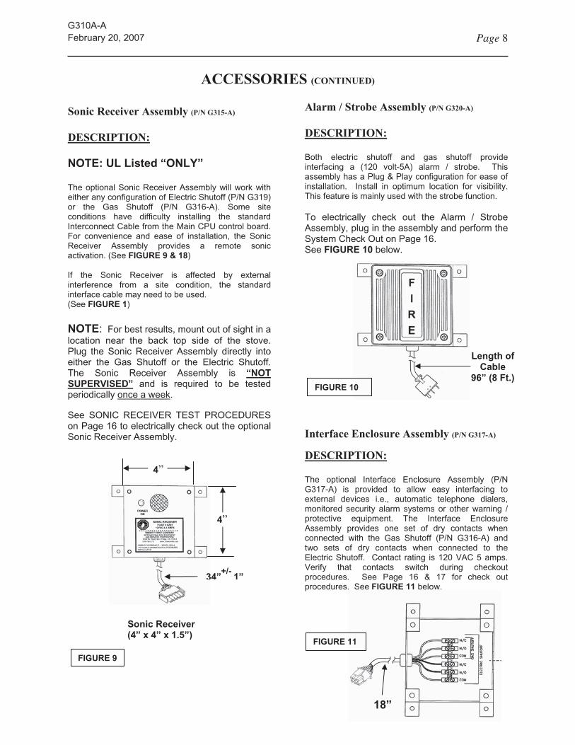
Sonic Receiver Assembly (P/N G315-A)
DESCRIPTION:
NOTE: UL Listed “ONLY”
The optional Sonic Receiver Assembly will work with either any configuration of Electric Shutoff (P/N G319) or the Gas Shutoff (P/N G316-A). Some site conditions have difficulty installing the standard Interconnect Cable from the Main CPU control board. For convenience and ease of installation, the Sonic Receiver Assembly provides a remote sonic activation. (See FIGURE 9 & 18)
If the Sonic Receiver is affected by external interference from a site condition, the standard interface cable may need to be used. (See FIGURE 1)
NOTE: For best results, mount out of sight in a location near the back top side of the stove. Plug the Sonic Receiver Assembly directly into either the Gas Shutoff or the Electric Shutoff. The Sonic Receiver Assembly is “NOT
SUPERVISED” and is required to be tested periodically once a week.
See SONIC RECEIVER TEST PROCEDURES on Page 16 to electrically check out the optional Sonic Receiver Assembly.
Alarm / Strobe Assembly (P/N G320-A)
DESCRIPTION:
Both electric shutoff and gas shutoff provide interfacing a (120 volt-5A) alarm / strobe. This assembly has a Plug & Play configuration for ease of installation. Install in optimum location for visibility. This feature is mainly used with the strobe function.
To electrically check out the Alarm / Strobe Assembly, plug in the assembly and perform the System Check Out on Page 16. See FIGURE 10 below.
Interface Enclosure Assembly (P/N G317-A)
DESCRIPTION:
The optional Interface Enclosure Assembly (P/N G317-A) is provided to allow easy interfacing to external devices i.e., automatic telephone dialers, monitored security alarm systems or other warning /protective equipment. The Interface Enclosure Assembly provides one set of dry contacts when connected with the Gas Shutoff (P/N G316-A) and two sets of dry contacts when connected to the Electric Shutoff. Contact rating is 120 VAC 5 amps. Verify that contacts switch during checkout procedures. See Page 16 & 17 for check out procedures. See FIGURE 11 below.
FIGURE 9
Length of
Cable
96” (8 Ft.) FIGURE 10
Sonic Receiver
(4” x 4” x 1.5”)
34”+/-
1”
4”
4”
FIGURE 11
18”

G310A-AFebruary 20, 2007 Page 9
ELECTRIC SHUTOFF (P/N G319)
The electric stove is shut off during system activation by two methods. With the electric shutoff one of the following is used. (1)- Using the interconnect cable (standard) from the Main CPU Control board terminal strip (P1-5 & 7) to the electric shutoff completes a hardwired signal which in turn activates the shutoff unit. (2) When using the Sonic Receiver board (optional), the shutoff continuously monitors for a “sonic” alarm from the Main CPU board located in the system enclosure. The Sonic Receiver board responds to the audible signal and activates the shutoff. Both methods cause all electrical power to the stove to shut off.In the event that the electric shutoff is activated or an interruption in power occurs, it must be reset. See FIGURE 15.
INSTALLATION
NOTE: Insure electric stove shutoff is installed
within the same room as the Main CPU control
board (part #G302) for proper unit operation.
1. Turn” OFF” electricity to the range. 2. Identify your electric plug configuration; 3-prong,
4-prong or hardwire. (See FIGURES 12A, 12B,
and 12C).
3. Remove the stove power cord from the wall outlet and plug it into the outlet on the stove shutoff unit (See FIGURE 15).
4. Insert the stove shutoff power cord into the wall outlet.
5. Plug the “Interconnect Cable” into the shutoff. 6. Install Interconnect cable between electric
shutoff and Main CPU. 7. Connect the spade lugs to terminal strip P1-5 &
7 on Main CPU. (See FIGURE 3 & 14)8. Turn “ON” electricity to range.
HARDWIRED SHUTOFF Description:
This option is available on the electric shut off if the power cord and receptacle are not needed and is hardwired by a certified electrician. (See FIGURE
12C)
3-PRONG
4-PRONG
HARDWIRED FIGURE 12C
FIGURE 13
FIGURE 12A
Typical connector configuration for
3 prong, 4 prong, and Hardwired
Electric Shutoff’s
FIGURE 12B

G310A-AFebruary 20, 2007 Page 10
SONIC ELECTRIC SHUTOFF
Description:
To convert the standard shutoff to a remote sonic version, the standard interface cable is replaced with the Sonic Receiver Assembly. Typical interface is interchangeable for both the interconnect cable and the Sonic Receiver board. Either interface connection plugs into the electric shutoff, depending on which interface option is chosen. In some cases a sonic version of the shutoff device may be required. If this is the case, the audible alarm is required to shut off the stove via the optional Sonic Receiver Board. (See FIGURE 9)
Reset Stove
1. The electric stove shutoff unit may be reset by locating the circuit breaker supplying power to the stove and turning it off and then back on, or
2. Momentarily unplugging the shutoff from the wall outlet and plugging it back in.
NOTE: Method two (2) requires the stove circuit
Breaker to be in the “ON” position. Method one
(1) is preferable since the stove does not need to
be moved.
FIGURE 15
OPTIONALALARM / STROBE (See FIGURE 10)
POWER CORD- 3 PRONG AND 4 PRONG OR A HARDWIRED CONFIGURATION (SEE FIGURE 12A, 12B, & 12C)
OPTIONAL INTERFACE ENCLOSURE ASSEMBLY (See FIGURE 11)
OPTIONALELECTRIC SHUTOFF RESET SWITCH
TO MAIN CPU (P1-5 & 7)
(SEE FIGURE 3)
FIGURE 14
INTERCONNECT CABLE IS STANDARD CONFIGURATION
SONIC RECEIVER ASSEMBLY (OPTIONAL-SEE FIGURE 9)

G310A-AFebruary 20, 2007 Page 11
GAS SHUTOFF (P/N G316-A)
The Gas Shutoff Assembly G316-A is the standard shutoff supplied with the G300A system. Features provided with this shutoff include the following:
TWO WAY
N/C VALVE
1. A “Fail Safe Mode” consisting of a Normally Closed (N/C) valve that is energized continually. Loss of power or activation due to a fire will close the valve, shutting off “gas flow” and “electrical power” to the stove.
2. Standard interface interconnect cable will be provided or optional “Sonic Receiver” board upon request.
FLEX SERVICE LINE
MANUAL GAS SHUTOFF VALVE 3. An extra set of dry contacts for switching external devices during system activation are provided.
4. The shutoff also has a manual “power reset” feature to eliminate any possibility of an automatic reset activation of the valve occurring after a fire or loss of power.
FIGURE 16
INSTALLATION OF GAS STOVE SHUTOFF GAS SHUTOFF CONTROL BOX
INSTALLATION NOTE:
Insure gas stove shutoff is installed within
the same room as the central processing
unit control board (Part #G302) for proper
unit operation.
1. Locate required tools and hardware for installation.
Turn “OFF” electric power and gas to stove
prior to installation.2. If stove is not unplugged, remove the plug from
the outlet.
3. Determine the optimal location either behind the stove or in an adjoining cabinet for installation of the Gas Shutoff Control Box (Part # G316-2). (See FIGURE 17) Consider accessibility to activate the manual reset. From the Gas Shutoff Control Box route the cables to gas valve and power cord to wall outlet.
NOTE: Check the length of cables for adequate length prior to installation of Gas Shutoff Control Box.
VALVE INSTALLATION
It is suggested that a certified plumber familiar with local and state codes install the gas valve (P/N # G316-1) on the incoming service line to the stove. Adhere to manufacturers installation and maintenance instructions.
Wiring must comply with local and national electrical codes.
The solenoid valve is designed for continuous duty cycle. When the solenoid valve is energized for a long period, the enclosure becomes hot and can be touched by hand only for an instant. This is a safe operating temperature.
FIGURE 17
Normally, the connection is made between the manual line shutoff and the flexible service line from the stove. Insure that manual valve is closed prior to installation of valve. (See FIGURE 16)
NOTE: The gas valve has an "in" and "out"
orientation to ensure that the valve is installed
correctly.
Install the “Gas Shutoff Control Box” before relocating the stove back for regular cooking conditions.

G310A-AFebruary 20, 2007 Page 12
GAS SHUTOFF CONTROL BOX
INSTALLATION (Continued)
See FIGURE 18 for the following steps:
4. Plug the valve into the connector on the Gas Shutoff Control Box.
5. Connect the interconnect cable or Optional Receiver Board into the Gas Shutoff Control Box.
6. If Interconnect Cable is used, route the cable from Gas Shutoff Control Box to the Main CPU board. Spade lugs on the interconnect cable connect to terminal strip P1-5 & 7 of the Main CPU board. (See FIGURE 3 page 5)
7. Plug the power cord from the stove into the Gas Shutoff Control Box and then the power cord for the Gas Shutoff Box into the wall outlet.
SONIC GAS SHUTOFF
Description:
To convert the standard shutoff to a remote sonic version, the standard interface cable is replaced with the Sonic Receiver Assembly. Typical interface is interchangeable for both the interconnect cable and the Sonic Receiver board. Either interface connection plugs into the electric shutoff, depending on which interface option is chosen. In some cases a sonic version of the shutoff device may be required. If this is the case, the audible alarm is required to shut off the stove via the optional Sonic Receiver Board. (See FIGURE 9)
Arming/ Resetting Gas Shutoff Assembly
1. Turn power “ON” to the stove.
CAUTION: “GAS WILL BE FLOWING TO
THE STOVE WHEN PERFORMING THE NEXT
STEP”
2. The “Gas Flow” indicator light should be lit. If not, push the “Power Reset” switch ( first ) and then the ”Valve Reset” switch (second) to arm the control box.
Note: In the event that the gas shutoff is activated or an interruption in power occurs, it must be reset.
See System Checkout Procedures on Page 16 & 17
FIGURE 18
PLUG POWER CORD INTO WALL OUTLET
POWER CORD FROM RANGE
VALVERESETGAS FLOW
INDICATOR
OPTIONALALARM / STROBE
(SEE FIGURE 10)
OPTIONAL INTERFACE ENCLOSURE ASSEMBLY (SEE FIGURE 11)
TO MAIN CPU (P1-5 & 7)
(SEE FIGURE 3)
POWERRESET
INTERCONNECT CABLE IS STANDARD CONFIGURATION
SONIC RECEIVER ASSEMBLY (OPTIONAL-SEE FIGURE 9)
G310A-AFebruary 20, 2007 Page 13
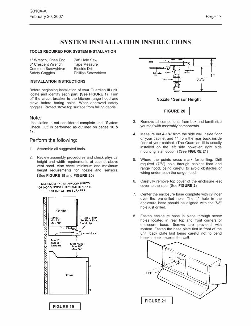
SYSTEM INSTALLATION INSTRUCTIONSTOOLS REQUIRED FOR SYSTEM INSTALLATION
1”3.75”
1" Wrench, Open End 7/8" Hole Saw 8" Crescent Wrench Tape Measure Common Screwdriver Electric Drill, Safety Goggles Phillips Screwdriver
INSTALLATION INSTRUCTIONS
Before beginning installation of your Guardian III unit, locate and identify each part. (See FIGURE 1) Turn off the circuit breaker to the kitchen range hood and stove before boring holes. Wear approved safety goggles. Protect stove top surface from falling debris.
Nozzle / Sensor Height
FIGURE 20
Note:3. Remove all components from box and familiarize
yourself with assembly components. Installation is not considered complete until “System Check Out” is performed as outlined on pages 16 & 17.
4. Measure out 4-1/4" from the side wall inside floor of your cabinet and 1" from the rear back inside floor of your cabinet. (The Guardian III is usually installed on the left side however; right side mounting is an option.) (See FIGURE 21)
Perform the following:
1. Assemble all suggested tools.
2. Review assembly procedures and check physical height and width requirements of cabinet above vent hood. Also check minimum and maximum height requirements for nozzle and sensors.(See FIGURE 19 and FIGURE 20)
5. Where the points cross mark for drilling. Drill required (7/8") hole through cabinet floor and range hood, being careful to avoid obstacles or wiring underneath the range hood.
6. Carefully remove top cover of the enclosure -set cover to the side. (See FIGURE 2)
7. Center the enclosure base complete with cylinder over the pre-drilled hole. The 1" hole in the enclosure base should be aligned with the 7/8" hole just drilled.
8. Fasten enclosure base in place through screw holes located in rear top and front corners of enclosure base. Screws are provided with system. Fasten the base plate first in front of the unit; back plate last being careful not to bend bracket back towards the wall.
FIGURE 21
FIGURE 19
G310A-AFebruary 20, 2007 Page 14
SYSTEM INSTALLATION INSTRUCTIONS (Cont'd)
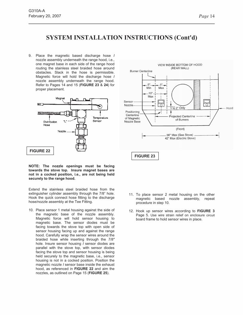
9. Place the magnetic based discharge hose Inozzle assembly underneath the range hood, i.e., one magnet base in each side of the range hood routing the stainless steel braided hose around obstacles. Slack in the hose is permissible. Magnetic force will hold the discharge hose Inozzle assembly underneath the range hood. Refer to Pages 14 and 15 (FIGURE 23 & 24) for proper placement.
NOTE: The nozzle openings must be facing
towards the stove top. Insure magnet bases are
not in a cocked position, i.e., are not being held
securely to the range hood.
Extend the stainless steel braided hose from the extinguisher cylinder assembly through the 7/8” hole. Hook the quick connect hose fitting to the discharge hose/nozzle assembly at the Tee Fitting.
10. Place sensor 1 metal housing against the side of the magnetic base of the nozzle assembly. Magnetic force will hold sensor housing to magnetic base. The sensor diodes must be facing towards the stove top with open side of sensor housing facing up and against the range hood. Carefully wrap the sensor wires around the braided hose while inserting through the 7/8" hole. Insure sensor housing I sensor diodes are parallel with the stove top, with sensor diodes facing the stove top and sensor housing is being held securely to the magnetic base, i.e., sensor housing is not in a cocked position. Position the magnetic nozzle I sensor base inside the exhaust hood, as referenced in FIGURE 22 and aim the nozzles, as outlined on Page 15 (FIGURE 25).
FIGURE 22
FIGURE 23
11. To place sensor 2 metal housing on the other magnetic based nozzle assembly, repeat procedure in step 10.
12. Hook up sensor wires according to FIGURE 3
Page 5. Use wire strain relief on enclosure circuitboard frame to hold sensor wires in place.

G310A-AFebruary 20, 2007 Page 15
AIMING NOZZLES
AIMING THE SPRAY NOZZLES AND
PLACEMENT OF TEMPERATURE SENSORS
1. Locate the centerline of the magnetic base nozzle assemblies directly over the burner centerline (front to back) as illustrated in FIGURE 23. If needed, the magnetic assemblies can be placed up to 5" inside the burner centerline to the inside of the hood. The magnetic bases are also to be between 1" Min. and 2" Max. back from the inside of the hood hip of the range hood. (See FIGURES 23 & 25)
2. Using a 1" box end wrench and a crescent wrench loosen the locking nut on the adjustable ball fitting a point 1/2 way between the center of the front and back burners.
Each nozzle shall be aimed at the respective centerpoint along the burner centerline, between the front and back burner. (Left nozzle -left aim point; right nozzle right aim point.) To adjust the nozzles see FIGURE 24 & 25. Be sure to re-tighten the locking nut after aiming is completed, being careful not to change nozzle positions from the correct aim point.
3. After retightening the swivel locking nut of eachnozzle, recheck nozzles are aimed correctly.
4. Attach the temperature sensors to the side of each Magnetic nozzle base, with the diodes pointed downward towards the stove top.
FIGURE 24
TARGET AREA FOR SPRAY NOZZLES
FIGURE 25
G310A-AFebruary 20, 2007 Page 16
SYSTEM CHECK OUT
SYSTEM CHECK-OUT AFTER INSTALLATION
CAUTION: To avoid accidental discharge “DO NOT REMOVE PULL PIN” at this time. Refer to Page 17, FIGURE 26 for this step AFTERsystem and shutoff check-out.
After aiming the spray nozzles and placement of the temperature sensors conduct final system check-out to include operation of the electric or gas shutoff by accomplishing the following:
1. Insure the 9V DC battery is installed in the central processing unit (CPU) board.
2. If the alarm sounds, remove the battery immediately and recheck the connections as shown in FIGURE 3 for one or more of the following:
A. Open or bad connection to the sensors B. Shorted sensor or frayed wires shorting. C. Open or bad connection to the electronic
release valve.3. ln the event of a low battery, the alarm will "chirp"
approximately once every 45 seconds. The unit is still operational, but the battery must be replaced to assure continued, uninterrupted operation.
SHUTOFF CHECK-OUT
INTERCONNECT CABLE TEST PROCEDURES
(IF OPTIONAL SONIC RECEIVER IS USED GO TO “SONIC RECEIVER” TEST PROCEDURES)
Insure the electric or gas shutoff has been installed in accordance with the instruction contained in this manual. See Page 9 &10 for Electric Range and Page 11 & 12 for Gas Range.
Perform the following:
Electric Stove: Turn on any burner to the high position until burner coil is hot.
For Gas Stove: Light any burner and turn to the high position.
Note: DO NOT REMOVE a sensor wire. This
enables the “FAIL SAFE” mode. Sensor
must have a short across the terminals to
simulate a “FIRE DETECT MODE”.
Use a wire and create a short across one of the sensor terminals (P1 -1 & 2 or P1-3 & 4).
IMPORTANT: REMAIN SHORTED FOR 20-30
SECONDS.
1. Verify that the release valve solenoid is activated. (See FIGURE 26)
2. After 20 – 30 seconds, remove the short across the sensor terminals. System alarm continues (Fire Detect Mode Disabled). Push K1 switch near LED on Main CPU board for Piezo alarm reset. (See FIGURE 3 )
3. Verify that the electric or gas shutoff has been activated by observing the test results. See “TEST RESULTS” below.
SONIC RECEIVER TEST PROCEDURES
(IF THE INTERCONNECT CABLE IS USED GO TO “INTERCONNECT TEST PROCEDURES”)
Insure the electric or gas shutoff has been installed in accordance with the instruction contained in this manual. See Page 10 for Electric Range and Page 11 & 12 for Gas Range. See page 8 for Sonic Receiver details.
Perform the following:
Sonic Receiver: Install unit and plug into shutoff. Verify that LED “Power On” light is on.
Electric Stove: Turn on any burner to the high position until burner coil is hot.
For Gas Stove: Light any burner and turn to the high position.
1. Locate and remove the positive (+) #2 heat sensor terminal wire connection (red lug) on the central processing unit control board terminal block. SEE
FIGURE 3.
2. Once removed, the audible Piezo Alarm on the Main CPU control board will activate.
NOTE: “Fail Safe Mode” is initiated. Though the
audible alarm has activated, extinguisher cylinder
release valve will not activate.
3. Allow Main CPU board audible alarm to sound for approximately 20-30 seconds, which will activate either the electric or gas shutoff via the Sonic Receiver board.
G310A-AFebruary 20, 2007 Page 17
SONIC RECEIVER TEST PROCEDURES (Continued)
4. Verify that the electric or gas shutoff has been activated by observing the test results. See “TEST RESULTS” below.
5. Once the shutoff (electric or gas) has activated, reconnect the positive (+) #2 heat sensor terminal wire connection (red lug) to the CPU board terminal block, See FIGURE 3, Page 5. Once reconnected the CPU board audible alarm will cease to sound and the CPU board will automatically reset itself. Observe that the red LED light beside the battery holder blinks approximately every 45 seconds once again. This indicates the CPU board has reset itself and the unit is operating.
TEST RESULTS
Electric Stove Shutoff Unit: Burner coil heat has decreased and all electrical power to the stove has been shut off, i.e. stove power light is off. Turn burner to OFF position. Reset the electric shutoff unit as outlined on Page 10 - FIGURE 15.
Gas Stove Shutoff Unit: Burner is no longer lit and all gas to the stove has been shut off, i.e., other burners cannot be lit. Electricity is turned off if Gas Shutoff P/N G316-A assembly is used. Turn burner to OFF position. Reset the gas shutoff unit as outlined on Page 12.
CAUTION: If the Guardian III Model G300-A fails to operate as described for either the Interconnect Cable or the Sonic Receiver configuration, contact the company the unit was purchased from or Guardian Safety Solutions for an authorized G service center for assistance.
ARMING YOUR SYSTEM
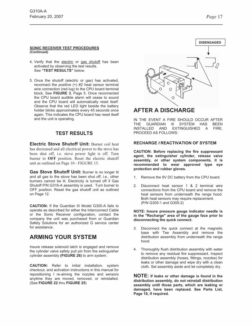
Insure release solenoid latch is engaged and remove the cylinder valve safety pull pin from the extinguisher cylinder assembly (FIGURE 26) to arm system.
CAUTION: Refer to initial installation, system checkout, and activation instructions in this manual for repositioning I re-aiming the nozzles and sensors anytime they are moved, removed, or reinstalled. (See FIGURE 22 thru FIGURE 25)
AFTER A DISCHARGE
DISENGAGED
IN THE EVENT A FIRE SHOULD OCCUR AFTER THE GUARDIAN III SYSTEM HAS BEEN INSTALLED AND EXTINGUISHED A FIRE, PROCEED AS FOLLOWS:
RECHARGE I REACTIVATION OF SYSTEM
CAUTION: Before replacing the fire suppressant
agent, the extinguisher cylinder, release valve
assembly, or other system components, it is
recommended to wear approved type eye
protection and rubber gloves.
1. Remove the 9V DC battery from the CPU board.
2. Disconnect heat sensor 1 & 2 terminal wire connections from the CPU board and remove the heat sensors from underneath the range hood. Both heat sensors may require replacement. (P/N G305-1 and G305-2)
NOTE: Insure pressure gauge indicator needle is
in the "Recharge" area of the gauge face prior to
disconnecting the quick connect.
3. Disconnect the quick connect at the magnetic base with Tee Assembly and remove the distribution assembly from underneath the range hood.
4. Thoroughly flush distribution assembly with water to remove any residual fire suppressant. Inspect distribution assembly (hoses, fittings, nozzles) for leaks or other damage and wipe dry with a clean cloth. Set assembly aside and let completely dry.
NOTE: If leaks or other damage is found in the
distribution assembly, do not reinstall distribution
assembly until those parts, which are leaking or
damaged, have been replaced. See Parts List,
Page 19, if required.

G310A-AFebruary 20, 2007 Page 18
AFTER A DISCHARGE (continued)
5. Disconnect extinguisher cylinder release valve terminal wire connections from the CPU board (See FIGURE 3, Page 5).
6. Remove the extinguisher cylinder assembly from the enclosure base by loosening the cylinder band.
7. Unscrew and remove the extinguisher cylinder manifold I siphon tube assembly from the extinguisher cylinder. Pour out any residual fire suppressant, which may be left in the extinguisher cylinder.
8. Refill extinguisher cylinder with 5 Ibs. (58 oz.) of Ansulex Low pH (Part #79372) fire suppressant.
9. Replace the extinguisher cylinder manifold "0" ring (Part #G303-D) and reinstall manifold / siphon tube assembly into the extinguisher cylinder. Do not combine I mix chemicals or suppressants.
CAUTION: Do not use extinguisher cylinder gauge
to determine when the intended charge pressure
has been reached.
10. Connect a nitrogen supply line to the ¼” male quick connect fitting and pressurize to 100 P.S.I.
11. Reinstall the extinguisher cylinder assembly in the enclosure base.
12. Refer to initial installation I system check-out Iactivation instructions to complete reinstallation Ireactivation of the system. (See FIGURES 3, 22,
23, 24, 25, and 26), Pages 5, 14, 15 and 17.
G310A-AFebruary 20, 2007 Page 19
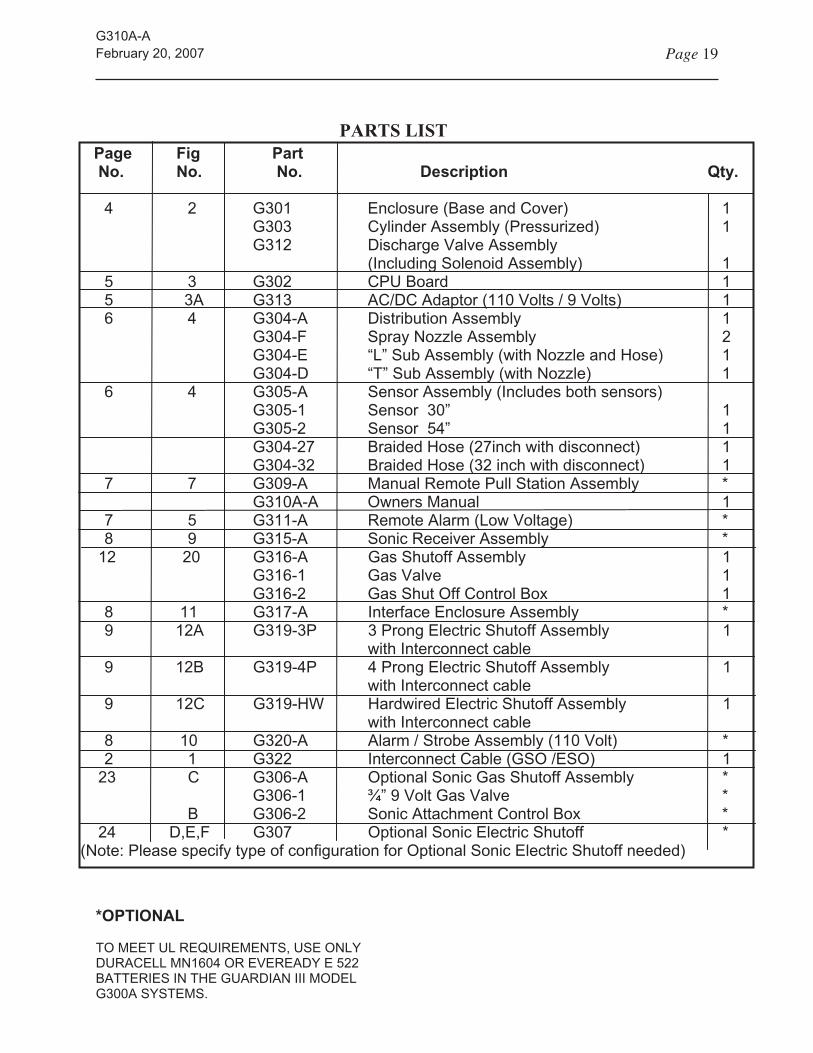
PARTS LIST Page Fig Part
No. No. No. Description Qty.
*OPTIONAL
TO MEET UL REQUIREMENTS, USE ONLY DURACELL MN1604 OR EVEREADY E 522 BATTERIES IN THE GUARDIAN III MODEL G300A SYSTEMS.
4 2 G301 Enclosure (Base and Cover) 1 G303 Cylinder Assembly (Pressurized) 1 G312 Discharge Valve Assembly (Including Solenoid Assembly) 1 5 3 G302 CPU Board 1
5 3A G313 AC/DC Adaptor (110 Volts / 9 Volts) 1 6 4 G304-A Distribution Assembly 1 G304-F Spray Nozzle Assembly 2 G304-E “L” Sub Assembly (with Nozzle and Hose) 1 G304-D “T” Sub Assembly (with Nozzle) 1 6 4 G305-A Sensor Assembly (Includes both sensors) G305-1 Sensor 30” 1 G305-2 Sensor 54” 1 G304-27 Braided Hose (27inch with disconnect) 1 G304-32 Braided Hose (32 inch with disconnect) 1 7 7 G309-A Manual Remote Pull Station Assembly * G310A-A Owners Manual 1 7 5 G311-A Remote Alarm (Low Voltage) * 8 9 G315-A Sonic Receiver Assembly * 12 20 G316-A Gas Shutoff Assembly 1 G316-1 Gas Valve 1 G316-2 Gas Shut Off Control Box 1 8 11 G317-A Interface Enclosure Assembly * 9 12A G319-3P 3 Prong Electric Shutoff Assembly 1 with Interconnect cable 9 12B G319-4P 4 Prong Electric Shutoff Assembly 1 with Interconnect cable 9 12C G319-HW Hardwired Electric Shutoff Assembly 1 with Interconnect cable 8 10 G320-A Alarm / Strobe Assembly (110 Volt) * 2 1 G322 Interconnect Cable (GSO /ESO) 1 23 C G306-A Optional Sonic Gas Shutoff Assembly * G306-1 ¾” 9 Volt Gas Valve * B G306-2 Sonic Attachment Control Box * 24 D,E,F G307 Optional Sonic Electric Shutoff *(Note: Please specify type of configuration for Optional Sonic Electric Shutoff needed)

G310A-AFebruary 20, 2007 Page 20
TROUBLESHOOTING GUIDE
CAUTION: DURING CHECK OUT PROCEDURES MAKE SURE SAFETY PULL PIN IS INSTALLED.
Main CPU Board (P/N G302)
Problem: Continuous Alarm
Check the following: (See FIGURE 3)
During test procedures, Push K1 on Main CPU to disable the alarm.
Verify terminals are tight on P1 terminal strip.
Sensor cable wires are not shorted or frayed.
Open or bad connection to solenoid release valve.
Bad sensor-replace one sensor at a time.
Release Solenoid Latch
Problem: No Activation of Latch
Check the following: (See FIGURE 3)
Terminals are tight on Main CPU P1-8 & 9.
Verify the red wire goes to P1-8 and the black wire goes to P1-9.
Use a Multi-meter to measure the DC Voltage signal on P1-8 (+) and P1-9 (-) during system checkout. If signal does not appear, replace CPU board. If signal exists, perform next step.
Disconnect wires from P1-8 & P1-9. Use a 9-volt battery and place the red wire on positive and the black wire on negative. If solenoid DOES NOT
ACTIVATE use a Multi-meter to measure the resistance between the two wires. The resistance should be approximately 190 ohms. If no indication of resistance, replace solenoid.
Electric Shutoffs (P/N G319)
Verify the configuration and determine if the electric shutoff is 1- Sonic or 2- Non-sonic and whether it is a 3 Prong, 4 Prong or Hardwired version.
Problem: No Electrical Power To Stove usingInterconnect Cable Configuration
Perform Electric Shutoff Checkout procedures on Page 16 that are applicable to right configuration.
Verify that the Interconnect cable wires to Main CPU control board are attached correctly on P1 terminal strip 5 (com) and 7 (N/O).
Verify power is getting to stove by turning on burner. If, no power, disconnect electric shutoff and plug stove directly into the wall.
If power to the stove exists by plugging directly into the wall, replace electric shutoff. If no power exist to the stove, check site condition.
For hardwired versions, have a certified electrician verify that the source power is supplied to the same side of the contactor as the orange wires from the ESO printed circuit board.
Problem: No Shutoff Activation using theInterconnect Cable
Perform Electric Shutoff Checkout procedures on Page 16 that are applicable to right configuration.
Confirm that power is supplied to the stove through the electric shutoff.
Verify that the connector on the “interconnect cable” is plugged into the electric shutoff and that the other end of the interconnect cable is connect to P1-5 & 7 on the Main CPU board.
Short across the interconnect cable terminated on P1-5 & 7 of the Main CPU board with a wire to complete the circuit in shut off. Activation should occur. If activation does NOT occur, replace the shutoff.
If activation occurs, reset the shutoff and perform INTERCONNECT CABLE TEST PROCEDURES
on Page 16 &17. Be sure to keep short across sensor for approximately 20-30 seconds to enable “Fire Detect Mode”. If activation does NOT occur at this point, replace the Main CPU board.
Problem: No Shutoff Activation using theSonic Receiver Assembly
Perform “Sonic Receiver Test Procedures” Checkout on Page 16.
Check that “Sonic Receiver Assembly” is plugged into shutoff. Power “ON” light will be lit.

G310A-AFebruary 20, 2007 Page 21
TROUBLESHOOTING GUIDE
(continued)
CAUTION: DURING CHECK OUT
PROCEDURES MAKE SURE SAFETY PULL
PIN IS INSTALLED.
Confirm that the installation of Sonic Receiver is not obstructed from receiving the audio signal. Verify that the location and the db level (loudness) is adequate by opening cabinet. If electric shutoff activates, installation of a remote alarm may be necessary to compensate for the type of cabinet or an Interconnect Cable will have to be used.
If any unknown interference occurs from a site condition the Interconnect Cable may have to be used.
Gas Shutoff (P/N G316-A)
Problem: No Electrical Power To Stove
Confirm power is supplied at the wall outlet. If no power to the stove exist, check the site condition.
If power exist at the wall outlet, unplug the stove from wall outlet and plug it into Gas Shutoff Control box.
Verify that the “Power Reset” push button switch is pushed. Electrical power is supplied to the stove. (See FIGURE 18)
DO NOT push the “VALVE RESET” switch at this time. Pushing the VALVE RESET switch will enable gas to flow to the stove.
If power still does NOT exist to the stove, unplug stove from the Gas Shutoff Control box and check for 115 VAC on the control box outlet. If there is no power, replace the control box.
Problem: No Gas Flow to Stove
Confirm that the “source power” is supplied to the Gas Shutoff Control box.
Verify that the “Power Reset” push button switch is pushed to supply power to the stove and to the the “Valve Reset” switch on the Gas Shutoff Control Box. (The Power Reset switch supplies power to the Valve Reset Switch. This is a safety feature.)
Push the “Valve Reset” switch for gas flow to the stove. The gas flow indicator light is lit.
If there is NO gas flow to the stove, verify that the gas valve is plugged into the Gas Shut Off Assembly control box. (The gas valve is normally closed and is energized when power is supplied to it.)
If there is still NO gas flow, unplug the gas valve and measure for 24 VAC voltage between the black and white wires. If there is voltage measured at the connector, replace the gas valve.
NOTE: After performing the above steps and there is 24VAC at plug and if the gas flow indicator light is not lit indicating gas flow, check the bulb indicator light. It may need to be replaced.
If there is NO voltage at the connector that plugs into the valve, replace the Gas Shutoff Control box.
Problem: No Shutoff Activation - Interconnect Cable or the Sonic Receiver Assy..
Confirm that power is supplied to “Gas Shutoff Control Box”. If no power exist, perform the steps under “No Electrical Power to Stove” on Page 20.
Perform the TEST PROCEDURES for either the INTERCONNECT CABLE or SONIC RECEIVER
ASSEMBLY on Page 16 &17. If no activation, replace the gas shutoff.
Sonic Receiver Assy (P/N G315-A)
Problem: No Sonic Activation
Perform “Sonic Receiver Test Procedures” Checkout on Page 16.
Check that “Sonic Receiver Assembly” is plugged into either the gas or electric shutoff. Power “ON” light will be lit. This indicates power is being supplied to the Sonic Receiver board.
Confirm that the installation of Sonic Receiver is not obstructed from receiving the audio signal. Verify that the location and the db level (loudness) is adequate by opening cabinet.
If shutoff activates by increasing the db level of sound, installation of a Remote Alarm may be necessary to compensate for the type of cabinet.
If the db level of loudness is adequate, replace the Sonic Receiver board or substitute an Interconnect Cable in place of the Sonic Receiver Assembly.
If any unknown interference occurs from a site condition the Interconnect Cable may have to be used. See Page 8 &16.

G310A-AFebruary 20, 2007 Page 22
OPTIONAL SONIC GAS SHUTOFF(P/N G306-A)
The optional sonic gas shutoff unit continuously monitors for an alarm from the CPU board located in the system enclosure. The alarm sounds to activate the sonic gas shutoff unit.
The optional sonic gas shutoff unit is powered with a 9-volt DC battery. Internal circuitry monitors the condition of the battery and will cause the alarm to 'chirp' approximately every 90 seconds when a low battery condition exists. Battery shall be replaced annually or when a low battery condition exists
Connect the Sonic Attachment Assy. Figure B to the coil on the gas valve in Figure C. Perform sonic test to verify activation.
INSTALLATION OF GAS STOVE SONIC
ACTIVATED SHUTOFF
NOTE: Insure gas stove sonic activated shutoff is
installed within the same room as the central
processing unit control board (Part #G302) for
proper unit operation.
It is suggested that a certified plumber familiar with local and state codes install this unit on the incoming service line to the stove.
Normally, the connection is made between the manual line shutoff and the flexible service line from the stove (See FIGURE A).
NOTE: The gas valve has an "in" and "out"
orientation to ensure that the valve is installed
correctly. FIGURE B
FIGURE A
CAUTION: PREMATURE ACTIVATION OF THE
ELECTRIC AND GAS STOVE SONIC SHUTOFF
UNITS CAN OCCUR, ONCE INSTALLED, IF YOUR
RESIDENTIAL SMOKE OR CARBON MONOXIDE
DETECTORS INADVERTENTLY ACTIVATE. BE
SURE TO RESET THE ELECTRIC OR GAS STOVE
SHUTOFF UNIT.
RESET VALVE
Alarm Connection Note:
When using the P/N G306-A Optional Sonic Gas Shutoff, the Main CPU (P/N G302) can be connected to automatic telephone dialers, monitored security alarm systems or other warning / protective equipment. The auxiliary outputs, terminal strip P1-5 & 7, provide a (1) second impulse every ten (10) seconds via a set of dry contacts rated at 5 AMP 24 VAC. In order to interface with the above items, a latching relay may be required.
Once activated, the gas valve remains in the closed position. In the event the valve is closed, it must be manually reset by depressing the reset button located on the bottom of the valve.
FIGURE C

G310A-AFebruary 20, 2007 Page 23
OPTIONAL SONIC ELECTRIC SHUTOFF (P/N G307)
The electric stove optional sonic shutoff unit continuously monitors for an alarm from the CPU board located in the system enclosure. The alarm sounds to activate the sonic shutoff unit. Once activated, all electrical power to the stove is shut off. In the event the unit is activated, it must be reset.
INSTALLATION OF ELECTRIC STOVE
SONIC ACTIVATED SHUTOFF
NOTE: Insure electric stove sonic activated
shutoff is installed within the same room as the
control processing unit control board (P/N #G302)
for proper unit operation. (Figure G)
1. Turn off electricity to the range. 2. Identify your electric plug configuration; 3-prong,
4-prong or hardwire. (See FIGURES D, E and F).
3. Remove the stove power cord from the wall outlet and plug it into the outlet on the sonic.
4. Insert the sonic stove shutoff power cord into the wall outlet.
5. Turn on electricity to range.
RESET STOVE
1. The electric stove sonic shutoff unit may be reset by locating the circuit breaker supplying power to the stove and turning it off and then back on, or
2. Momentarily unplugging the unit from the wall outlet and plugging it back in.
NOTE: This method requires the stove circuit
Breaker to be in the ON position. Method one (1)
is preferable since the stove does not need to be
moved.
FIGURE D
FIGURE E
FIGURE F
FIGURE G
Alarm Connection Note:
When using the P/N G307 Optional Sonic Electric Shutoff, the Main CPU (P/N G302) can be connected to automatic telephone dialers, monitored security alarm systems or other warning / protective equipment. The auxiliary outputs, terminal strip P1-5 & 7, provide a (1) second impulse every ten (10) seconds via a set of dry contacts rated at 5 AMP 24 VAC. In order to interface with the above items, a latching relay may be required.

PLACE STAMPHERE
Guardian Safety Solutions International8701 Carpenter Freeway
Suite 230Dallas, Texas 75247
LIMITED WARRANTY Guardian Residential Range-Top Automatic Fire Protection System
Guardian Safety Solutions International Inc. [GSSI] warrants to the original consumer purchaser that its Guardian Range Top Automatic Fire Protection System [Guardian System] shall be free of defects in materials or workmanship for one year from the date of purchase under normal residential use.
During the warranty period, GSSI will, at its option, repair or replace the Guardian System without charge for parts or labor. The Guardian System, or defective parts, must be returned with proof of purchase directly to GSSI, 8701 Carpenter Frwy. Suite 230 Dallas, Texas 75247. You must prepay the transporta-tion [postage] and insurance costs.
This warranty does not cover installa-tion, adjustment in the home, accidental discharge, labor costs for removal or in-stallation, damage due to accident, mis-use, abuse, fl ood, other Acts of God, and damage resulting from improper or un-authorized repair or modifi cations and any incidental or consequential damages.
Some states do not allow the exclusion or limitation of incidental or consequential damage, or allow limitation on how long an implied warranty lasts, so the above limitations or exclusions may not apply to you. This warranty gives you specifi c legal rights, and you may also have other rights which vary from state to state. This warranty is given in lieu of any other ex-pressed or implied warranty.
Printed in U.S.A.

Owner’s Registration Card
Please complete this card. It helps to establish your date of purchase and will help us contact you if we have additional information regarding our system. Just mail - the card is already addressed. Thank You.
NAME:
ADDRESS:
PURCHASE DATE:
SYSTEM ID:
SYSTEM ID:
SERIAL NO:
SERIAL NO:
First Initial Last Name
Sex:
M F
Street or P.O. Box
City State Zip Code
Month Day Year
COMMENTS:
Keep this part for your records
Owner’s Record CardGUARDIAN Residential Range Top Automatic Fire Protection System
PURCHASED FROM INSTALLED BY
DATE: DATE:
Guardian Safety Solutions International 8701 Carrpenter Freeway Suite 230
Dallas, Texas 75247 (972) 252-6201 * (972) 594-7826 * Toll Free: (800) 786-2178
www.GuardianSSI.com
creo

8701 John Carpenter Freeway Suite 230 Dallas, Texas 75247
Fax: (972) 594 - 7826Phone: (972) 252 - 6201Toll Free: (800) 786 - 2178
www.GuardianSSI.com