The Feasibility, Constructability, and Efficacy of Tire ...62106009.pdf · different slurry cutoff...
80
Contractor’s Report to the Board The Feasibility, Constructability, and Efficacy of Tire-Derived Aggregate as a Component in Slurry Cutoff Walls Produced under contract by: CSU, Chico Research Foundation June 2006
Transcript of The Feasibility, Constructability, and Efficacy of Tire ...62106009.pdf · different slurry cutoff...
Contractor’s Report to the Board
The Feasibility, Constructability, and Efficacy of Tire-Derived Aggregate as a Component in Slurry Cutoff Walls Produced under contract by:
CSU, Chico Research Foundation June 2006
S T A T E O F C A L I F O R N I A
Arnold Schwarzenegger Governor
Linda S. Adams Secretary for Environmental Protection
•
INTEGRATED WASTE MANAGEMENT BOARD Margo Brown Board Chair
Gary Peterson Board Member
Rosalie Mulé Board Member
Jeffrey Danzinger Board Member
Cheryl Peace Board Member
Pat Wiggins Board Member
•
Mark Leary Executive Director
For additional copies of this publication, contact:
Integrated Waste Management Board Public Affairs Office, Publications Clearinghouse (MS–6)
1001 I Street P.O. Box 4025
Sacramento, CA 95812-4025 www.ciwmb.ca.gov/Publications/
1-800-CA-WASTE (California only) or (916) 341-6306
Publication #621-06-009 Printed on recycled paper containing a minimum of 30 percent postconsumer fiber.
Copyright © 2005 by the California Integrated Waste Management Board. All rights reserved. This publication, or parts thereof, may not be reproduced in any form without permission.
Prepared as part of contract no. IWM–C2069X (total contract amount: $30,000, includes other services).
The California Integrated Waste Management Board (CIWMB) does not discriminate on the basis of disability in access to its programs. CIWMB publications are available in accessible formats upon request
by calling the Public Affairs Office at (916) 341-6300. Persons with hearing impairments can reach the CIWMB through the California Relay Service, 1-800-735-2929.
Disclaimer: This report to the Board was produced under contract by the CSU, Chico Research Foundation. The statements and conclusions contained in this report are those of the contractor and not necessarily those of the California Integrated Waste Management Board, its employees, or the State of California and should not be cited or quoted as official Board policy or direction. The State makes no warranty, expressed or implied, and assumes no liability for the information contained in the succeeding text. Any mention of commercial products or processes shall not be construed as an endorsement of such products or processes.
i
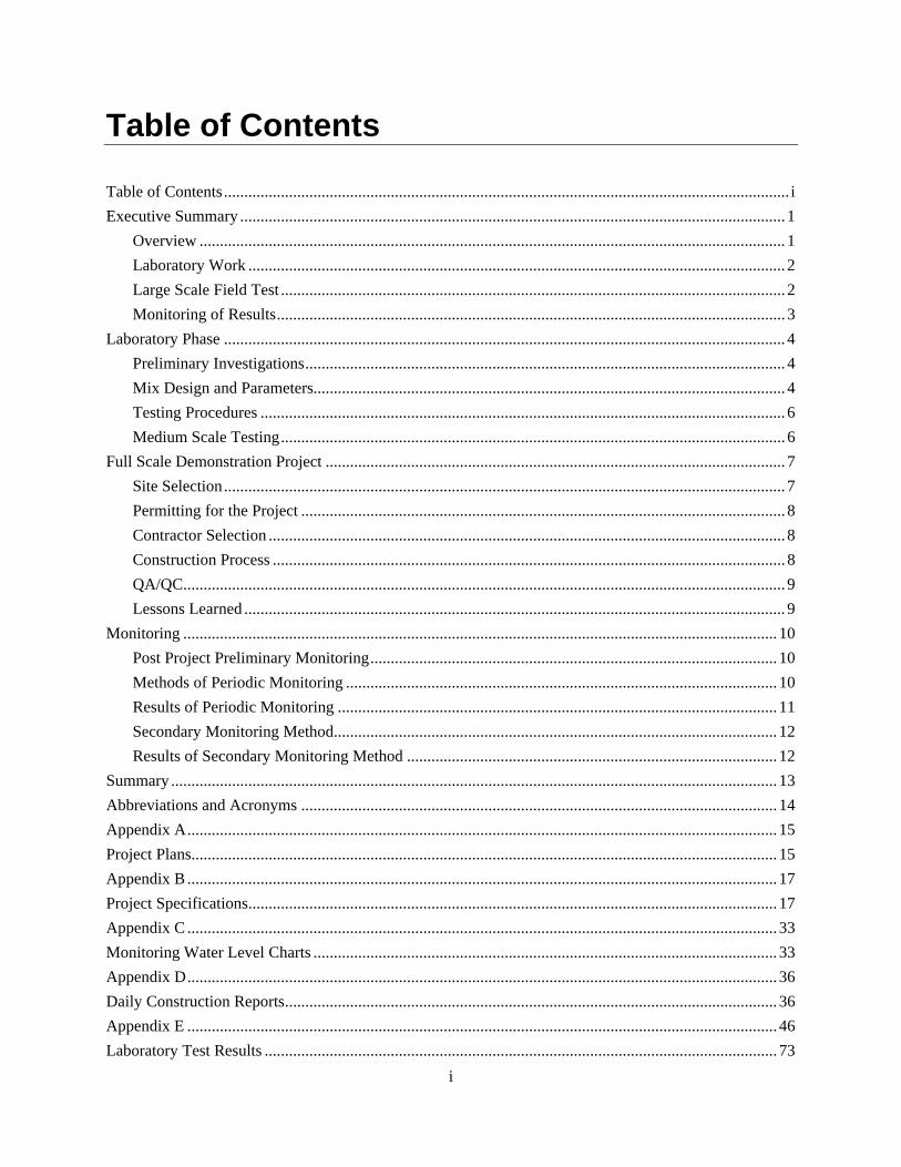
Table of Contents Table of Contents........................................................................................................................................... i Executive Summary ...................................................................................................................................... 1
Overview ................................................................................................................................................ 1 Laboratory Work .................................................................................................................................... 2 Large Scale Field Test ............................................................................................................................ 2 Monitoring of Results............................................................................................................................. 3
Laboratory Phase .......................................................................................................................................... 4 Preliminary Investigations...................................................................................................................... 4 Mix Design and Parameters.................................................................................................................... 4 Testing Procedures ................................................................................................................................. 6 Medium Scale Testing............................................................................................................................ 6
Full Scale Demonstration Project ................................................................................................................. 7 Site Selection.......................................................................................................................................... 7 Permitting for the Project ....................................................................................................................... 8 Contractor Selection ............................................................................................................................... 8 Construction Process .............................................................................................................................. 8 QA/QC.................................................................................................................................................... 9 Lessons Learned ..................................................................................................................................... 9
Monitoring .................................................................................................................................................. 10 Post Project Preliminary Monitoring.................................................................................................... 10 Methods of Periodic Monitoring .......................................................................................................... 10 Results of Periodic Monitoring ............................................................................................................ 11 Secondary Monitoring Method............................................................................................................. 12 Results of Secondary Monitoring Method ........................................................................................... 12
Summary ..................................................................................................................................................... 13 Abbreviations and Acronyms ..................................................................................................................... 14 Appendix A................................................................................................................................................. 15 Project Plans................................................................................................................................................ 15 Appendix B ................................................................................................................................................. 17 Project Specifications.................................................................................................................................. 17 Appendix C ................................................................................................................................................. 33 Monitoring Water Level Charts .................................................................................................................. 33 Appendix D................................................................................................................................................. 36 Daily Construction Reports......................................................................................................................... 36 Appendix E ................................................................................................................................................. 46 Laboratory Test Results .............................................................................................................................. 73

ii
Executive Summary Overview
This project was originally developed conceptually as a potential reuse for large quantities of waste tires which may be recycled by cutting them into tire shreds. Tire shreds have unique physical properties which may be used in various civil engineering applications. In 1998, a research grant was awarded to the CSU, Chico Research Foundation to evaluate the feasibility of incorporating tires shreds into a levee slurry cutoff wall. Professor Richard G. Holman authored the study.
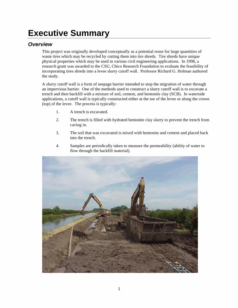
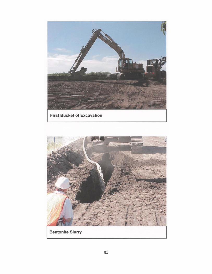
A slurry cutoff wall is a form of seepage barrier intended to stop the migration of water through an impervious barrier. One of the methods used to construct a slurry cutoff wall is to excavate a trench and then backfill with a mixture of soil, cement, and bentonite clay (SCB). In waterside applications, a cutoff wall is typically constructed either at the toe of the levee or along the crown (top) of the levee. The process is typically:
1. A trench is excavated.
2. The trench is filled with hydrated bentonite clay slurry to prevent the trench from caving in.
3. The soil that was excavated is mixed with bentonite and cement and placed back into the trench.
4. Samples are periodically taken to measure the permeability (ability of water to flow through the backfill material).
1

In the 1990’s the United States Army Corps of Engineers (USACOE) constructed more than 25 river miles of slurry cutoff walls per year on various rivers in Northern California. Additionally, cutoff wall contracts were let by various government agencies including the California Department of Water Resources (DWR), and the United States Bureau of Reclamation (USBOR). The hypothesis for this project was that a large quantity of recycled tires could be incorporated into the backfill, alleviating the various piles of waste tires stockpiled in the State of California and providing an effective barrier to water migration.
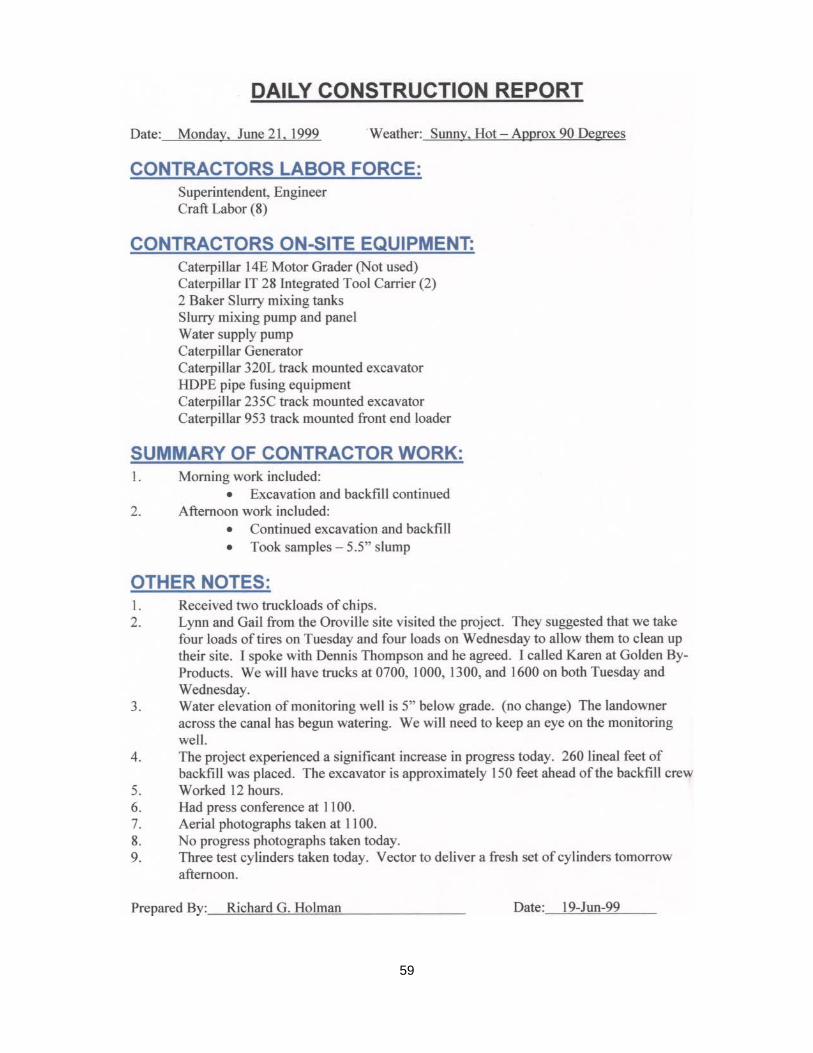
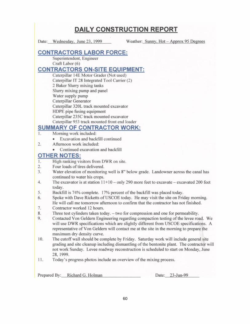
The Recycled Tire Slurry Cutoff Wall Demonstration Project was funded by the California Integrated Waste Management Board as a potential source for the reuse of waste tires. The project had four distinct stages:
1. Laboratory Testing
2. Medium Scale Testing
3. Large Scale Field Testing - Implementation
4. Monitoring of Results
Laboratory Work In 1998-1999, preliminary laboratory work was performed to determine if in fact, there was a method in which the soil, cement, bentonite, and tire shreds could be mixed resulting in a product that behaved similar to backfill materials being used in traditional SCB cutoff walls. The target used for measurement of performance was the USACOE specifications with three major criteria including:
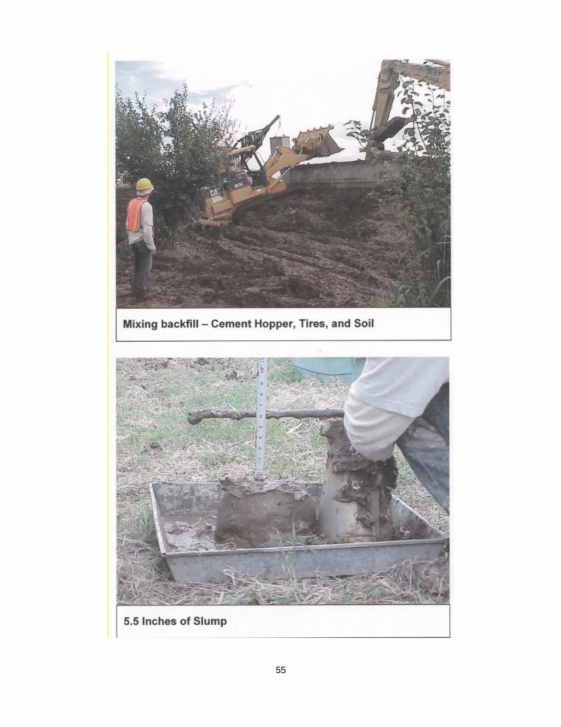
1. Slump – 100–150 mm (4-6 inches)
2. Permeability – Less than 5 x 10⁻⁷ cm/sec
3. Compressive strength (fc) – Less than 100 psi
Various sizes of rubber were tested from crumb rubber to as large as 8 inch tire shreds.
After a design mix was established, a medium scale mix was constructed using a ready-mix concrete truck. From the results of this test, the mix was slightly modified and preparation for the large scale project commenced.
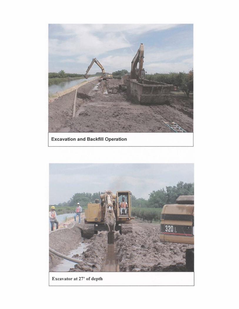
Large Scale Field Test In May of 1999, a prequalification of contractors was conducted. Bid documents were prepared and bids were requested. In June of 1999, a construction contract in the amount of $243,000 was awarded to Inquip Construction. The project consisted of construction of 1,400 lineal feet of cutoff wall on a levee in Gridley, CA. The wall was constructed 30 feet deep.
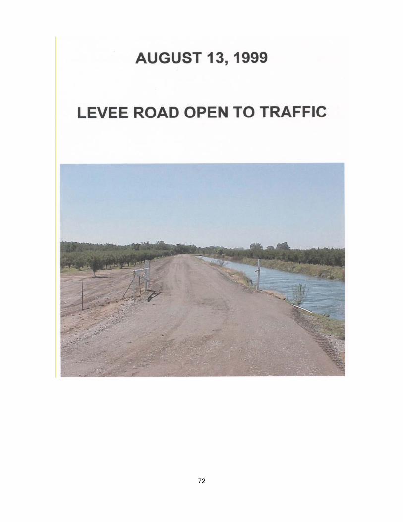
The site selected is a DWR levee between the Sutter-Colusa canal and the Feather River. This location was selected because the canal adjacent to the levee is drained and filled annually thus providing a good opportunity for monitoring.
2

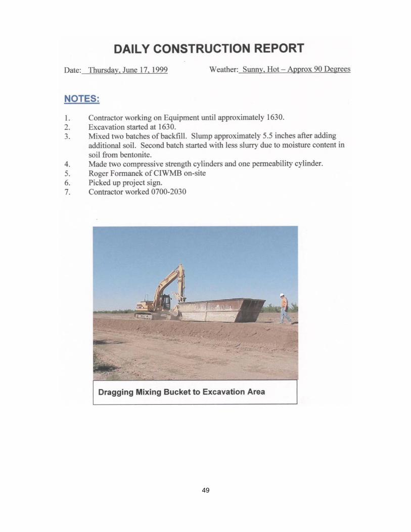
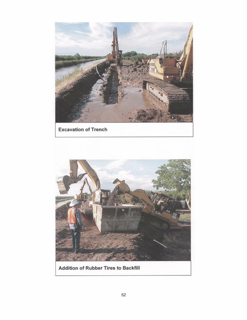
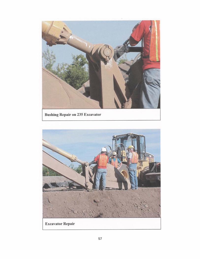
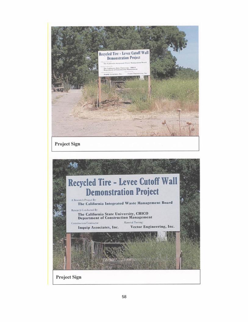
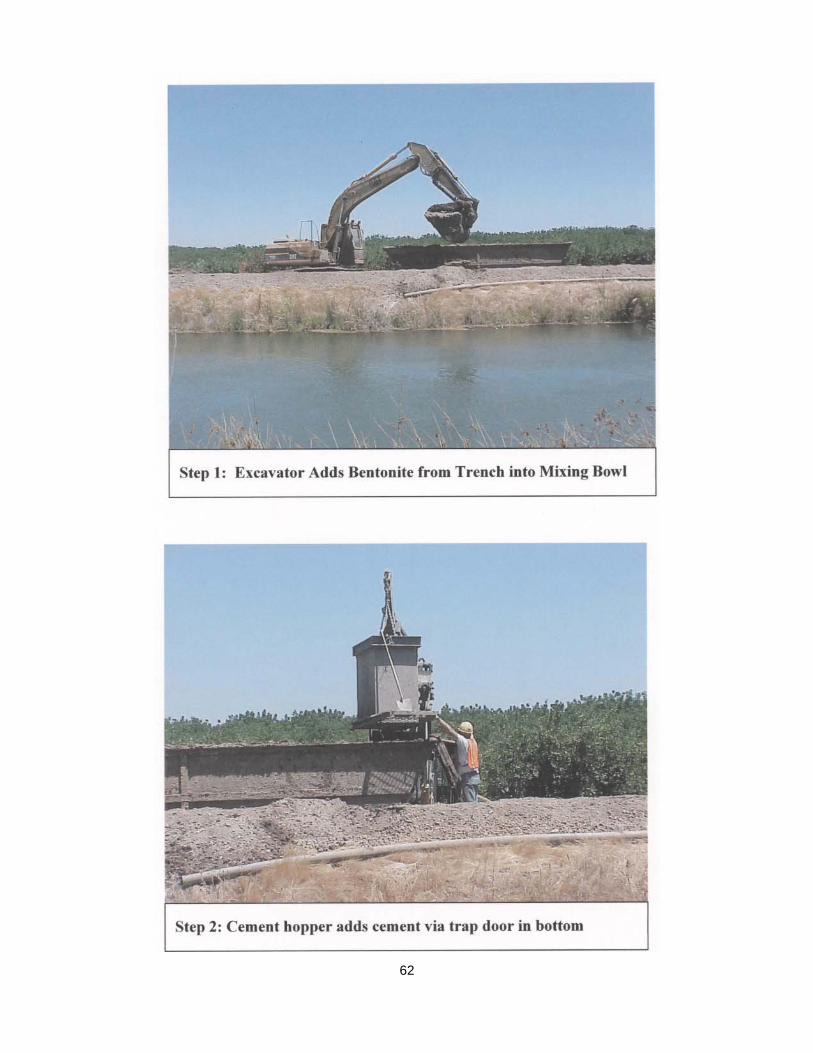
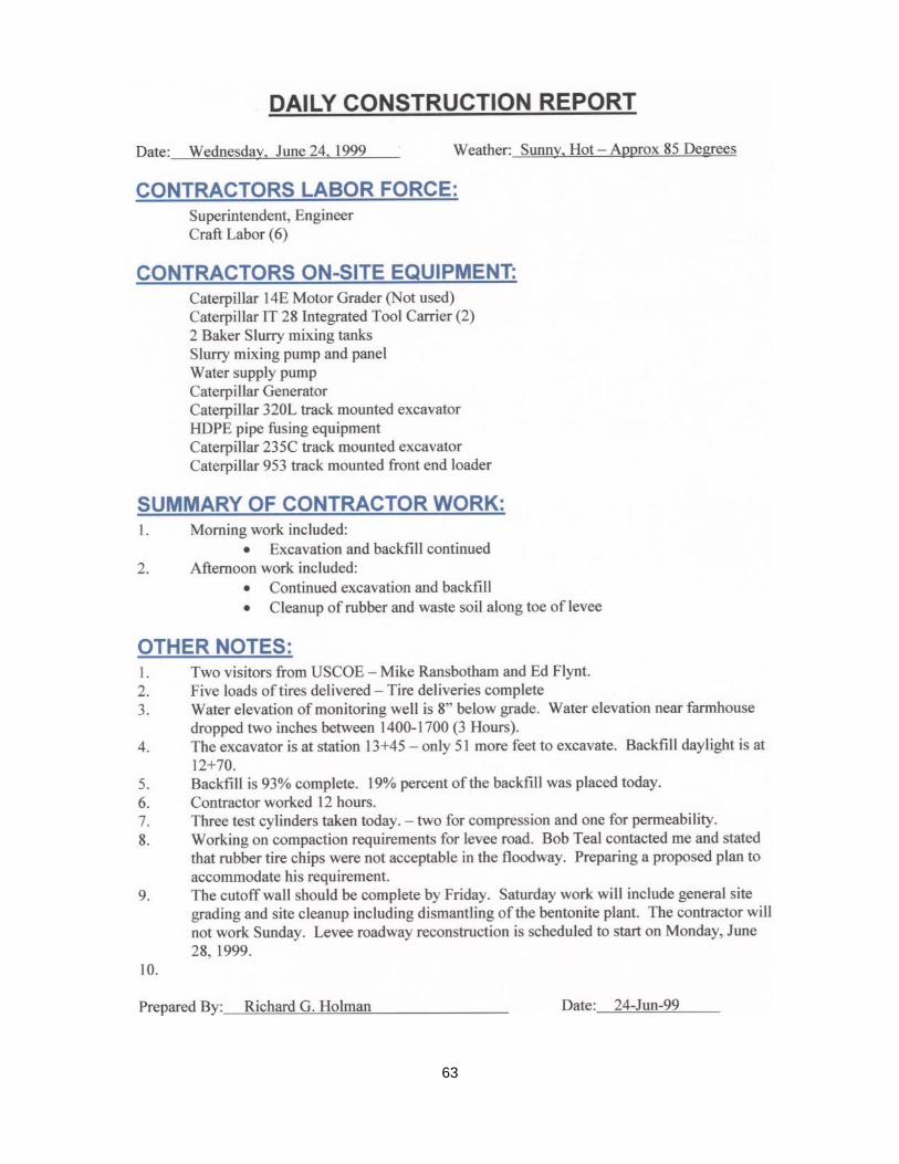
The cutoff wall took 30 days to complete. The project was constructed using two excavators, a track loader, and an integrated tool carrier. As the excavation progressed, the soil was placed in a 15 cubic yard (CY) mixing bin similar to a large garbage dumpster. Proper amounts of soil, cement, bentonite, and tire shreds were mixed and then placed at the opposite end of the excavation. As one excavator progressed with digging, the second excavator followed with the backfill so that the trench was not open more than approximately 100 feet at any given time. At the end of each shift, fence panels were placed over the excavation as a safety precaution to prevent someone from falling into the trench.
The contractor was required to follow USACOE specifications. Slump was measured on a regular basis. Custom cylinders were manufactured to conduct permeability tests. Compressive strength tests were conducted using 6” x 12” concrete test cylinders. All tests met specification.
The Recycled Tire Slurry Cutoff Wall Demonstration Project utilized 475 tons of tires. The tires were supplied to the project by the CIWMB at no charge to the project. Most of the tires used came from a legacy site in Oroville, CA. Procedurally, the contractor indicated that there was no additional cost or productivity loss due to incorporation of the tires into the backfill.
Monitoring of Results After the project was constructed, nine-four inch diameter monitoring wells were installed. The monitoring wells provide an opportunity to measure the depth of the ground water to determine if water was migrating from the canal, through (or around) the cutoff wall.
Weekly groundwater measurements were taken over the course of two years. Preliminary results indicated that there was water moving from the canal to the adjacent land. In other words, when the canal was filled, the groundwater level on the opposite side of the wall increased as well.
In May, 2005, the canal was filled. Prior to filling the canal, water level logging equipment was installed. The water level logging equipment was programmed to take water levels in fifteen minute intervals. After evaluation of this data, it was determined that the water appears to be migrating through the levee at both ends of the cutoff wall (not through the wall). This finding concurs with the permeability laboratory tests. From all data available, it appears that the water is making an “end around” on the cutoff wall.
3
Laboratory Phase
Preliminary Investigations Prior to commencement of laboratory testing, an informal literature review was conducted. Meetings were held with the USACOE engineering staff, and site visits were made to two different slurry cutoff walls construction sites. It became apparent that a Soil-Cement-Bentonite mix design was fairly well documented however there were significant obstacles when incorporating recycled tires into the mix.
Some of these obstacles included:
• Method of mixing materials in a large scale field test
• Method of testing permeability
• Method of testing slump
• Buoyancy of the tires
• Variations of soil classification used in lab tests from those actually found at the site
The results of these preliminary investigations concluded that there are various methods used to construct a slurry cutoff wall. The first project visited mixed the soil, cement, and bentonite using a dozer adjacent to the excavation. The mixing area was referred to as a “mixing bowl”. The second project utilized a large mixing box similar to a dumpster.
Another significant issue was the desire of CIWMB to maximize the use of tires. After significant discussions with the CIWMB, it was determined that crumb rubber was not preferred due to the cost of production. This presented a challenge regarding the testing methods which could be used.
Professor Dana Humphrey from the University of Maine who is a recognized expert in recycled tire projects was contacted. Dr. Humphrey had significant concerns about the potential for buoyancy. His concern was that the tires would “float” in the bentonite slurry as the backfill material was placed.
All of these concerns were significant and could not be ignored during the mix design process.
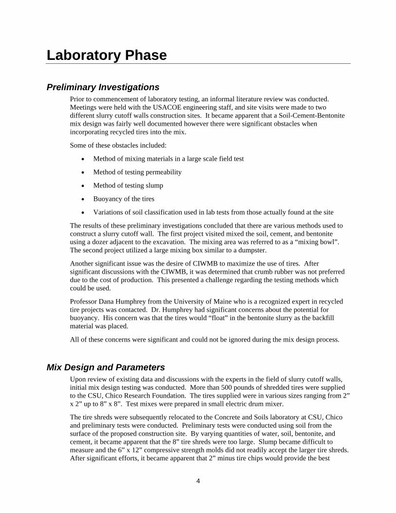
Mix Design and Parameters Upon review of existing data and discussions with the experts in the field of slurry cutoff walls, initial mix design testing was conducted. More than 500 pounds of shredded tires were supplied to the CSU, Chico Research Foundation. The tires supplied were in various sizes ranging from 2” x 2” up to 8” x 8”. Test mixes were prepared in small electric drum mixer.
The tire shreds were subsequently relocated to the Concrete and Soils laboratory at CSU, Chico and preliminary tests were conducted. Preliminary tests were conducted using soil from the surface of the proposed construction site. By varying quantities of water, soil, bentonite, and cement, it became apparent that the 8” tire shreds were too large. Slump became difficult to measure and the 6” x 12” compressive strength molds did not readily accept the larger tire shreds. After significant efforts, it became apparent that 2” minus tire chips would provide the best
4
workability and efficacy. At this time, 500 pounds of 2” minus tire shreds was delivered to CSU, Chico and an additional 500 pounds was delivered to the independent testing lab Vector Engineering.
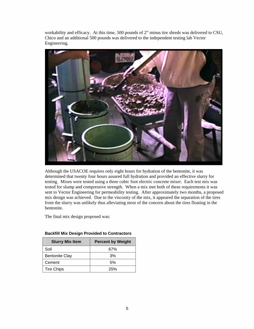
Although the USACOE requires only eight hours for hydration of the bentonite, it was determined that twenty four hours assured full hydration and provided an effective slurry for testing. Mixes were tested using a three cubic foot electric concrete mixer. Each test mix was tested for slump and compressive strength. When a mix met both of these requirements it was sent to Vector Engineering for permeability testing. After approximately two months, a proposed mix design was achieved. Due to the viscosity of the mix, it appeared the separation of the tires from the slurry was unlikely thus alleviating most of the concern about the tires floating in the bentonite.
The final mix design proposed was:
Backfill Mix Design Provided to Contractors
Slurry Mix Item Percent by Weight
Soil 67% Bentonite Clay 3% Cement 5% Tire Chips 25%
5

Testing Procedures Slump testing was conducted using the standard slump cone (ASTM C-143). The slump cone is considered accurate unless the maximum aggregate size exceeds 1.5 inches. For obvious reasons, the standard slump cone was not acceptable when using tire shreds. Even with smaller shreds, the tire chips tended to “stack” thus providing inaccurate results. To alleviate this concern, a Kelly Ball was utilized. The Kelly Ball utilizes a 6” diameter, 30 pound ball attached to a rod. A sample of slurry mix is prepared and struck off. The ball is then released and the depth of penetration is measured. The depth of measured can then be correlated to slump. The Kelley Ball test was formerly standardized in ASTM C-360-92.
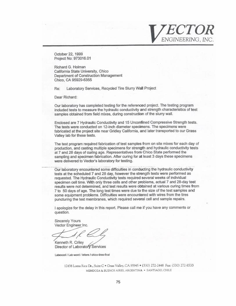
Permeability Testing was conducted at Vector Engineering. Due to the size of the tire chips, special test cylinders had to be constructed. The cylinders were constructed of twelve inch diameter plastic pipe with a plywood bottom. The test procedure used was ASTM D-5084. It should be noted that the USACOE requires hydraulic conductivity not to exceed 5 x 10⁻⁷ cm/sec. This is the equivalent of 0.0000005 cm/sec. In some cases, the project achieved only 2.4 x 10⁻⁷ cm/sec. This difference is minimal and given the margin of error, it was determined to be acceptable.
Medium Scale Testing In spring of 1999, a test was performed at Vector Engineering in Grass Valley, CA. This test involved mixing two separate batches of backfill material. With soil obtained from the site, there were two mixes prepared using a standard Cement mix transit truck.
The first mix used included the proposed mix design less the tires. The purpose of this test was to ensure that the matrix of soil-cement-bentonite would in fact meet the project objectives. The second test was the actual proposed mix design described above.
Both of these mixes were tested for both permeability as well as compressive strength. Although there were difficulties with the custom cylinders used for permeability testing, the mix was deemed adequate to proceed with construction of the large scale test project.
6
Full Scale Demonstration Project
Site Selection Criteria for site selection included:
• Accessibility
• Acceptability to the landowner
• Indications of hydraulic conductivity
• Reasonable scale due to limited funding
• Location – Northern California
Numerous contacts were made with the water districts in the Northern California region including:
• Biggs-West Gridley Water District
• Butte Water District
• Levee District No. 1
• Plumas Mutual Water District
• Sutter Extension Water District
• Levee District No, 9
• Western Canal Water District
After numerous conversations with the water districts as well as various engineering firms, Mr. Paul Russell who is the manager and director of the Sutter Extension Water District confirmed that he had a potential site approximately 5 miles south of Gridley, California. He indicated that the levee had been documented with indications of hydraulic conductivity (seepage)
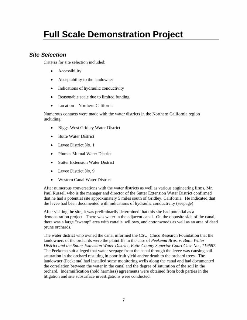
After visiting the site, it was preliminarily determined that this site had potential as a demonstration project. There was water in the adjacent canal. On the opposite side of the canal, there was a large “swamp” area with cattails, willows, and cottonwoods as well as an area of dead prune orchards.
The water district who owned the canal informed the CSU, Chico Research Foundation that the landowners of the orchards were the plaintiffs in the case of Peekema Bros. v. Butte Water District and the Sutter Extension Water District, Butte County Superior Court Case No., 119687. The Peekema suit alleged that water seepage from the canal through the levee was causing soil saturation in the orchard resulting in poor fruit yield and/or death to the orchard trees. The landowner (Peekema) had installed some monitoring wells along the canal and had documented the correlation between the water in the canal and the degree of saturation of the soil in the orchard. Indemnification (hold harmless) agreements were obtained from both parties in the litigation and site subsurface investigations were conducted.
7

In July, 1998, three soil borings were conducted on the crown of the levee. The soil borings were supervised by the independent testing lab, Vector Engineering and soil classifications were obtained using the Standard Penetration Test. Samples indicated that the levee was constructed of clay with thin layers of silt and sand. Based on the N-values of the Standard Penetration Tests, it was determined that a thirty foot deep wall should prevent any hydraulic conductivity between the canal and the adjacent orchard.
Permitting for the Project Prior to commencing construction, all environmental and construction permits had to be addressed including:
• California Environmental Quality Act (CEQA)
• California Department of Water Resources (DWR) Reclamation Board Permit
• California Department of Fish and Game (DFG) 1600 Agreement
• US Army Corps of Engineers (USACOE) 404 Permit
Contractor Selection It was determined that there were sufficient information in the plans and specifications to put the project out to bid as a lump sum fixed price contract. Prior to issuing bid documents, the CSU, Chico Research Foundation project team issued a Contractor Prequalification form to ensure that only qualified bidders would submit a price for the project.
The process revealed two contractors who were experienced in Slurry Cutoff Walls in the region. Inquip Construction, and Geo-Con Construction. Fixed price bids were received and Inquip was the lowest responsive, responsible bidder.
A fixed price contract for $243,000 was awarded to Inquip Construction.
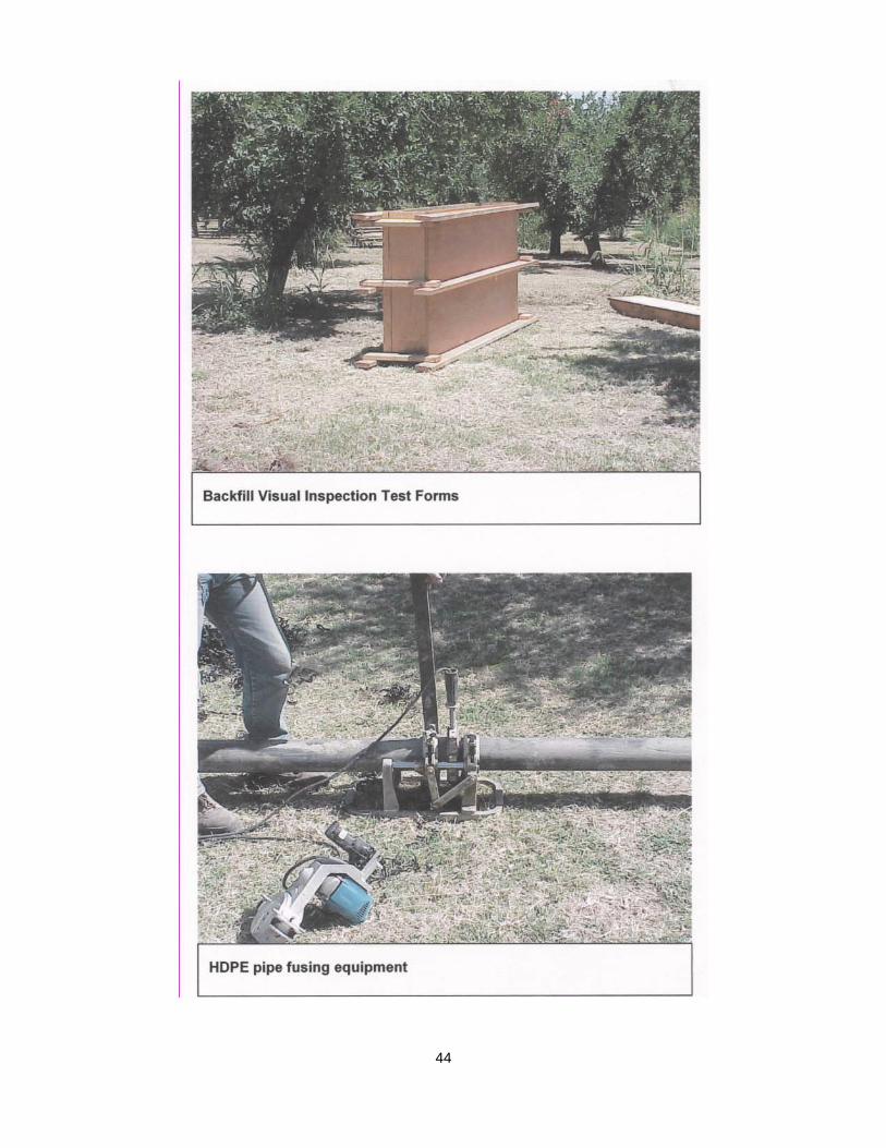
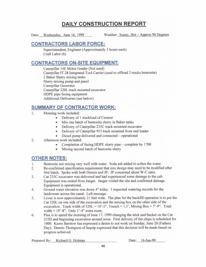
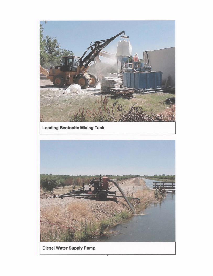
Construction Process The contractor mobilized the project on June 12, 1999. The process of setting up temporary power, bentonite mixing tanks, and the HDPE slurry supply pipe took approximately five working days. Excavation of the cutoff wall commenced on June 17, 1999. The equipment utilized included:
• 2 Caterpillar excavators – One at each end of the trench. The lead excavator was digging the trench and the second excavator was mixing and placing the Soil-Cement-Bentonite-Tire mix for backfill.
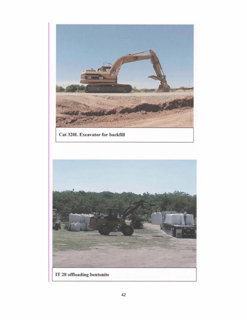
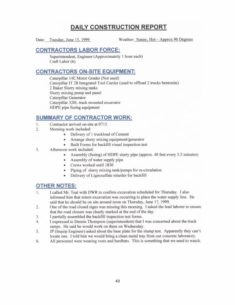
• 1 Caterpillar Integrated Tool Carrier (ITC) – This piece of equipment served many purposes. With it interchangeable components, it can serve as a forklift to offload cement and bentonite from the delivery trucks. The ITC can also attach a front end bucket to serve as a loader, and a boom which allowed carrying heavy loads. The primary function of the ITC was to deliver cement to the mixing bin.
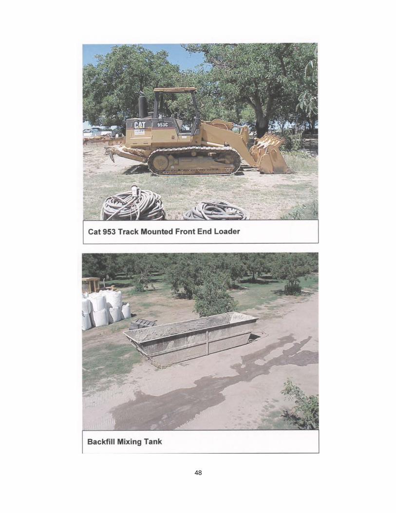
• 1 Caterpillar 953 Track Loader – The track loader is similar to a rubber tired front end loader only it is mounted on tracks for traction and flotation. The track loader was used to load soil and tire chips into the mixing bin. Once all materials were measured and
8
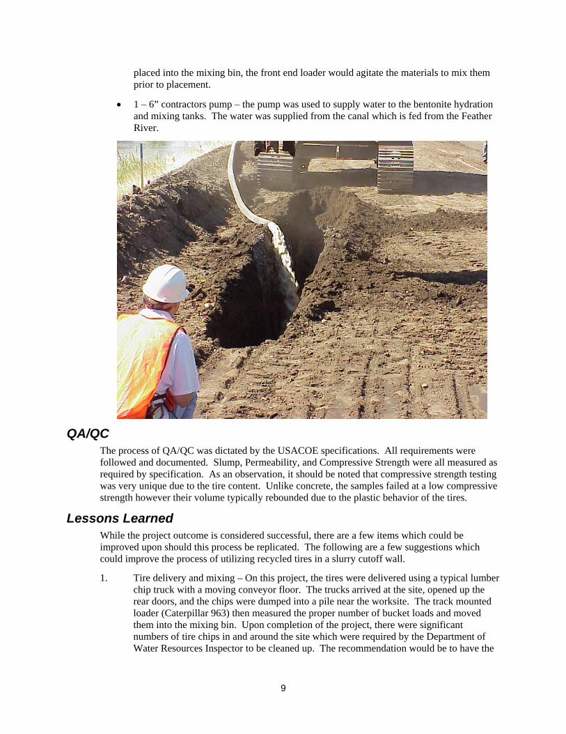
placed into the mixing bin, the front end loader would agitate the materials to mix them prior to placement.
• 1 – 6” contractors pump – the pump was used to supply water to the bentonite hydration and mixing tanks. The water was supplied from the canal which is fed from the Feather River.
QA/QC The process of QA/QC was dictated by the USACOE specifications. All requirements were followed and documented. Slump, Permeability, and Compressive Strength were all measured as required by specification. As an observation, it should be noted that compressive strength testing was very unique due to the tire content. Unlike concrete, the samples failed at a low compressive strength however their volume typically rebounded due to the plastic behavior of the tires.
Lessons Learned While the project outcome is considered successful, there are a few items which could be improved upon should this process be replicated. The following are a few suggestions which could improve the process of utilizing recycled tires in a slurry cutoff wall.
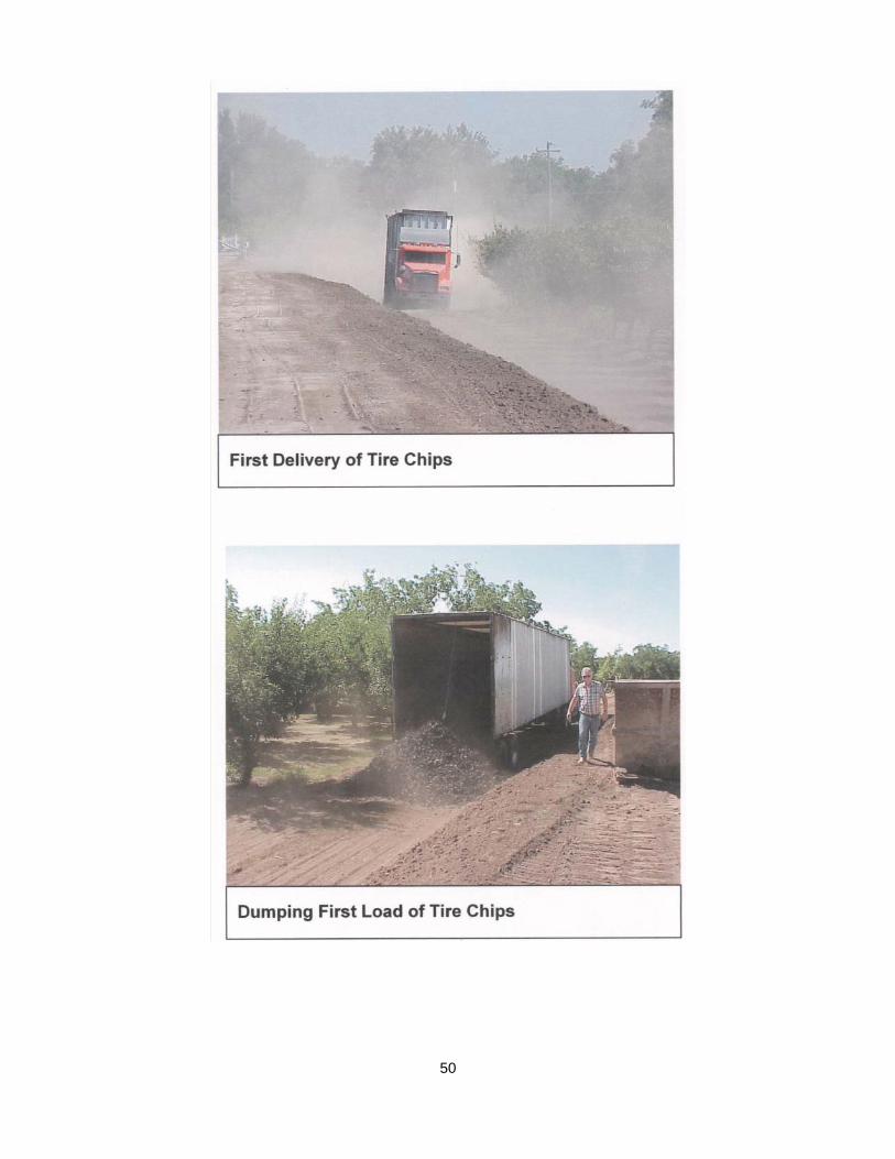
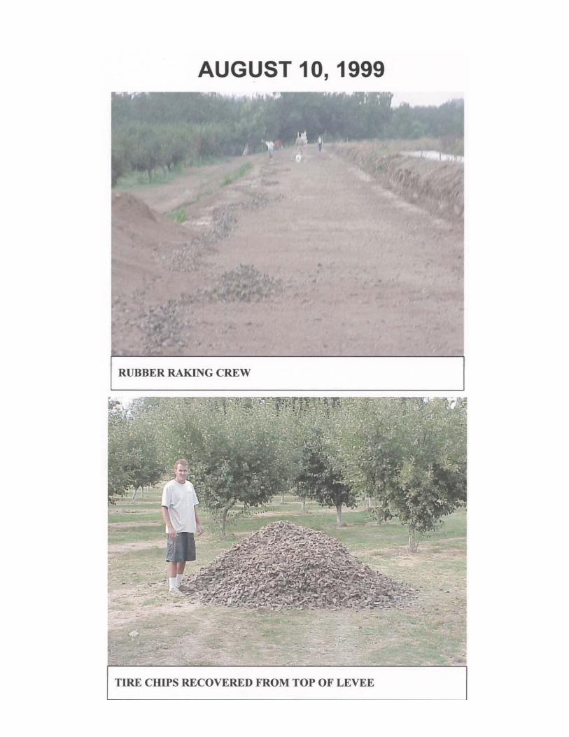
1. Tire delivery and mixing – On this project, the tires were delivered using a typical lumber chip truck with a moving conveyor floor. The trucks arrived at the site, opened up the rear doors, and the chips were dumped into a pile near the worksite. The track mounted loader (Caterpillar 963) then measured the proper number of bucket loads and moved them into the mixing bin. Upon completion of the project, there were significant numbers of tire chips in and around the site which were required by the Department of Water Resources Inspector to be cleaned up. The recommendation would be to have the
9
tires measured at the chipping facility and placed in bags or bins for placement into the mixing bin.
2. Backfill – It is suggested that the trench, not be backfilled to the upper limit. If the trench is backfilled to the top and the road is reconstructed, there are tire chips sticking out of the finished cutoff wall. It is suggested that the backfill be held to approximately one foot below the crown of the finished roadway. Clay soil could then be used in the top one foot of the wall with aggregate base on the finished surface.
Monitoring Post Project Preliminary Monitoring
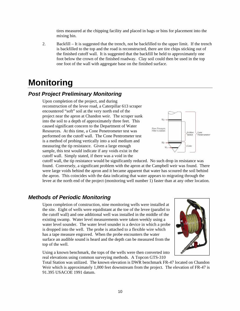
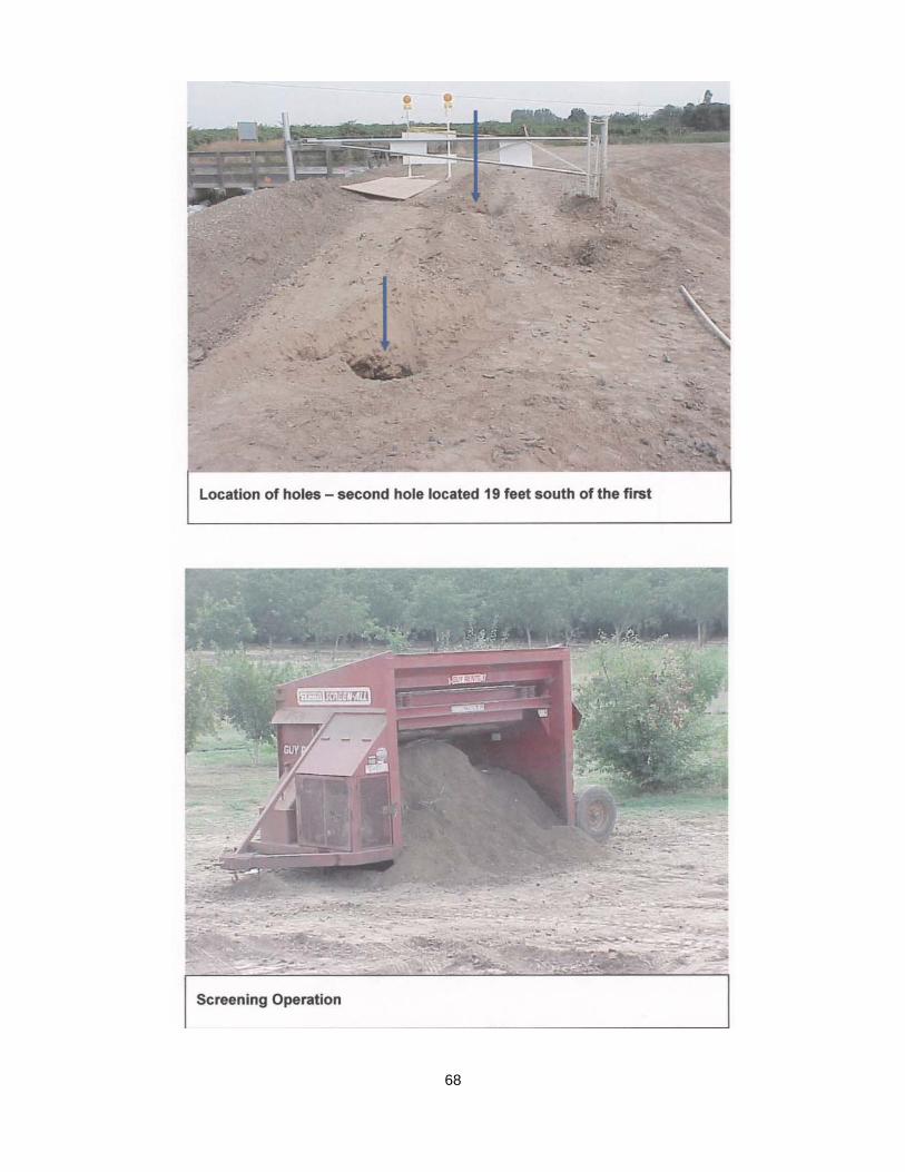
Upon completion of the project, and during reconstruction of the levee road, a Caterpillar 613 scraper encountered “soft” soil at the very north end of the project near the apron at Chandon weir. The scraper sunk into the soil to a depth of approximately three feet. This caused significant concern to the Department of Water Resources. At this time, a Cone Penetrometer test was performed on the cutoff wall. The Cone Pentrometer test is a method of probing vertically into a soil medium and measuring the tip resistance. Given a large enough sample, this test would indicate if any voids exist in the cutoff wall. Simply stated, if there was a void in the cutoff wall, the tip resistance would be significantly reduced. No such drop in resistance was found. Conversely, a significant problem with the apron at the Campbell weir was found. There were large voids behind the apron and it became apparent that water has scoured the soil behind the apron. This coincides with the data indicating that water appears to migrating through the levee at the north end of the project (monitoring well number 1) faster than at any other location.
Methods of Periodic Monitoring
Upon completion of construction, nine monitoring wells were installed at the site. Eight of wells were equidistant at the toe of the levee (parallel to the cutoff wall) and one additional well was installed in the middle of the existing swamp. Water level measurements were taken weekly using a water level sounder. The water level sounder is a device in which a probe is dropped into the well. The probe is attached to a flexible wire which has a tape measure engraved. When the probe encounters the water surface an audible sound is heard and the depth can be measured from the top of the well.
Using a known benchmark, the tops of the wells were then converted into real elevations using common surveying methods. A Topcon GTS-310 Total Station was utilized. The known elevation is DWR benchmark FR-47 located on Chandon Weir which is approximately 1,000 feet downstream from the project. The elevation of FR-47 is 91.395 USACOE 1991 datum.
10
Using this data and the topographic survey conducted, the tops of the wells were found to have the following elevations:
Well Elevation Data
Well Number Elevation (ft)
1 89.16 2 89.36 3 89.30 4 88.72 5 87.78 6 89.50 7 90.96 8 92.08 9 82.10
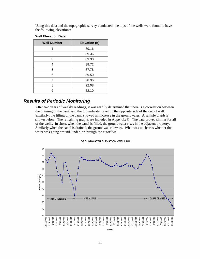
Results of Periodic Monitoring After two years of weekly readings, it was readily determined that there is a correlation between the draining of the canal and the groundwater level on the opposite side of the cutoff wall. Similarly, the filling of the canal showed an increase in the groundwater. A sample graph is shown below. The remaining graphs are included in Appendix C. The data proved similar for all of the wells. In short, when the canal is filled, the groundwater rises in the adjacent property. Similarly when the canal is drained, the groundwater lowers. What was unclear is whether the water was going around, under, or through the cutoff wall.
GROUNDWATER ELEVATION - WELL NO. 1
74
75
76
77
78
79
80
81
82
83
84
12/1
1/20
03
12/2
5/20
03
1/8/
2004
1/22
/200
4
2/5/
2004
2/19
/200
4
3/4/
2004
3/18
/200
4
4/1/
2004
4/15
/200
4
4/29
/200
4
5/13
/200
4
5/27
/200
4
6/10
/200
4
6/24
/200
4
7/8/
2004
7/22
/200
4
8/5/
2004
8/19
/200
4
9/2/
2004
9/16
/200
4
9/30
/200
4
10/1
4/20
04
10/2
8/20
04
11/1
1/20
04
11/2
5/20
04
12/9
/200
4
12/2
3/20
04
1/6/
2005
1/20
/200
5
2/3/
2005
2/17
/200
5
3/3/
2005
3/17
/200
5
3/31
/200
5
4/14
/200
5
DATE
ELEV
ATI
ON
(FT)
CANAL DRAINED CANAL FULL CANAL DRAINED
11
Secondary Monitoring Method To answer the question of how the water was migrating from the canal to the adjacent field, a water level data logger was installed in each well prior to the canal being filled in April, 2005. The logger used was a WL-15X Water Level Logger produced and distributed by Global Water Instrumentation, Inc. The water level data logger is a device installed into the well and programmed to take elevation readings at a given time interval. For this project, the data loggers were programmed to take elevation readings every 15 minutes for a two week period. The loggers were installed on Friday, April 22, 2005 and retrieved on Friday, May 6, 2005. The Joint Board Water District began filling the canal on Monday, April 25, 2005.
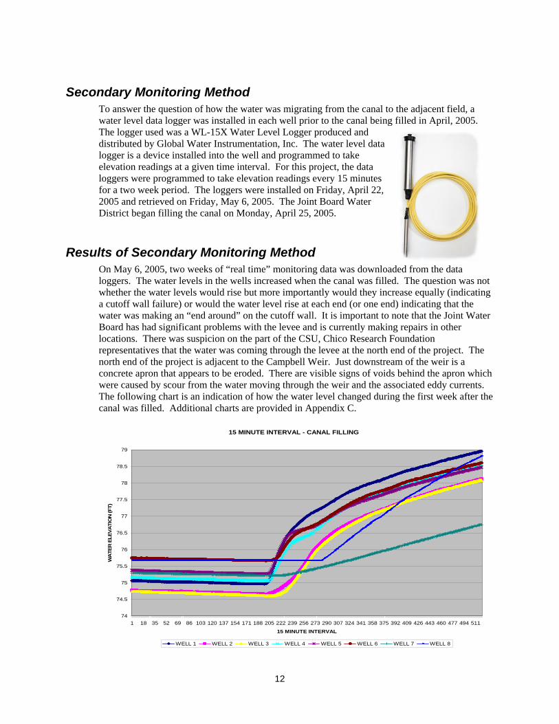
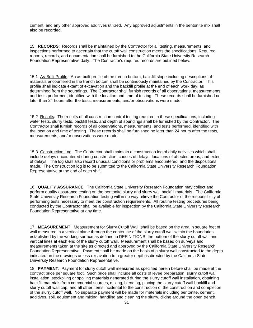
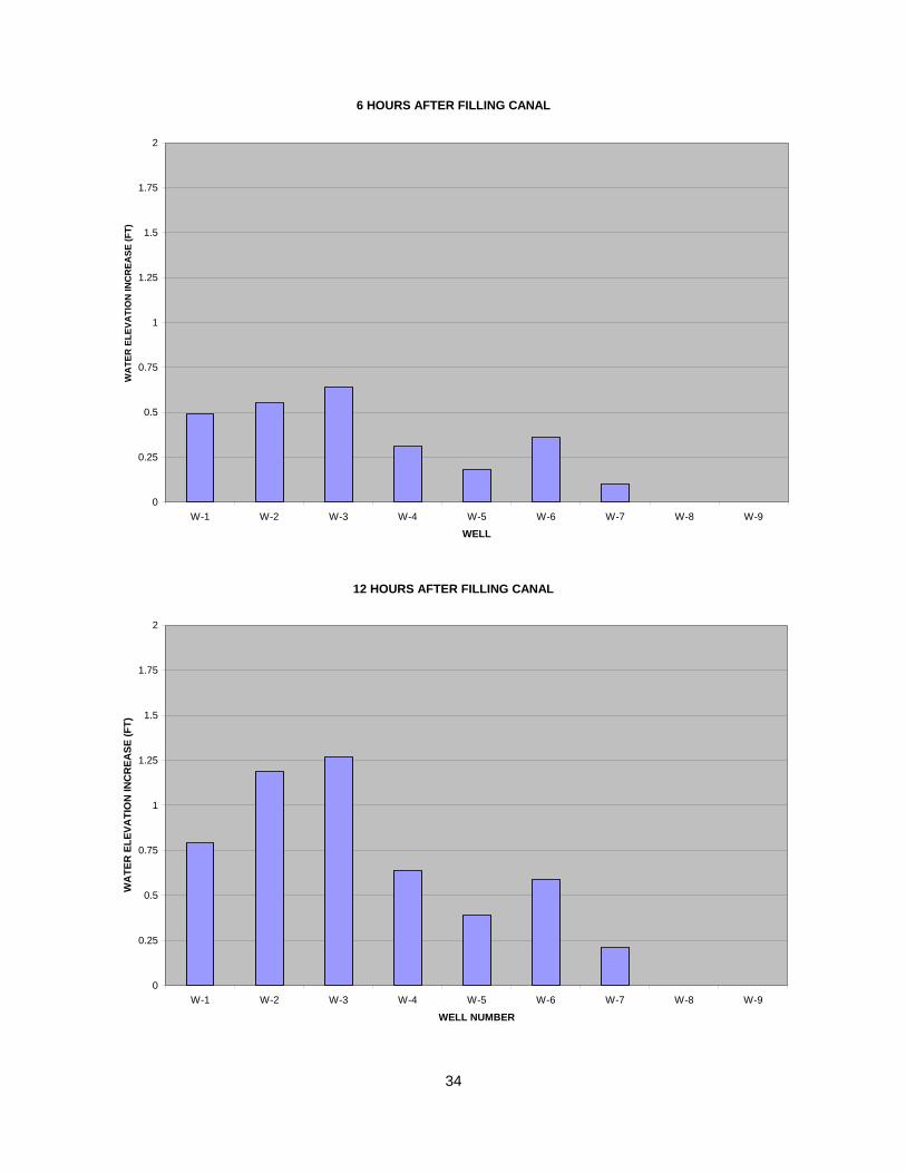
Results of Secondary Monitoring Method On May 6, 2005, two weeks of “real time” monitoring data was downloaded from the data loggers. The water levels in the wells increased when the canal was filled. The question was not whether the water levels would rise but more importantly would they increase equally (indicating a cutoff wall failure) or would the water level rise at each end (or one end) indicating that the water was making an “end around” on the cutoff wall. It is important to note that the Joint Water Board has had significant problems with the levee and is currently making repairs in other locations. There was suspicion on the part of the CSU, Chico Research Foundation representatives that the water was coming through the levee at the north end of the project. The north end of the project is adjacent to the Campbell Weir. Just downstream of the weir is a concrete apron that appears to be eroded. There are visible signs of voids behind the apron which were caused by scour from the water moving through the weir and the associated eddy currents. The following chart is an indication of how the water level changed during the first week after the canal was filled. Additional charts are provided in Appendix C.
15 MINUTE INTERVAL - CANAL FILLING
74
74.5
75
75.5
76
76.5
77
77.5
78
78.5
79
1 18 35 52 69 86 103 120 137 154 171 188 205 222 239 256 273 290 307 324 341 358 375 392 409 426 443 460 477 494 511
15 MINUTE INTERVAL
WA
TER
ELE
VATI
ON
(FT)
WELL 1 WELL 2 WELL 3 WELL 4 WELL 5 WELL 6 WELL 7 WELL 8
12
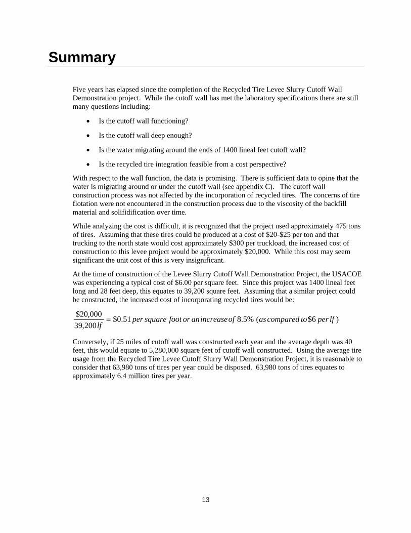
Summary
Five years has elapsed since the completion of the Recycled Tire Levee Slurry Cutoff Wall Demonstration project. While the cutoff wall has met the laboratory specifications there are still many questions including:
• Is the cutoff wall functioning?
• Is the cutoff wall deep enough?
• Is the water migrating around the ends of 1400 lineal feet cutoff wall?
• Is the recycled tire integration feasible from a cost perspective?
With respect to the wall function, the data is promising. There is sufficient data to opine that the water is migrating around or under the cutoff wall (see appendix C). The cutoff wall construction process was not affected by the incorporation of recycled tires. The concerns of tire flotation were not encountered in the construction process due to the viscosity of the backfill material and solifidification over time.
While analyzing the cost is difficult, it is recognized that the project used approximately 475 tons of tires. Assuming that these tires could be produced at a cost of $20-$25 per ton and that trucking to the north state would cost approximately $300 per truckload, the increased cost of construction to this levee project would be approximately $20,000. While this cost may seem significant the unit cost of this is very insignificant.
At the time of construction of the Levee Slurry Cutoff Wall Demonstration Project, the USACOE was experiencing a typical cost of $6.00 per square feet. Since this project was 1400 lineal feet long and 28 feet deep, this equates to 39,200 square feet. Assuming that a similar project could be constructed, the increased cost of incorporating recycled tires would be:
)6$(%5.851.0$200,39
000,20$ lfpertocomparedasofincreaseanorfootsquareperlf
=
Conversely, if 25 miles of cutoff wall was constructed each year and the average depth was 40 feet, this would equate to 5,280,000 square feet of cutoff wall constructed. Using the average tire usage from the Recycled Tire Levee Cutoff Slurry Wall Demonstration Project, it is reasonable to consider that 63,980 tons of tires per year could be disposed. 63,980 tons of tires equates to approximately 6.4 million tires per year.
13

Abbreviations and Acronyms
CIWMB: California Integrated Waste Management Board
DWR: California Department of Water Resources
DFG: California Department of Fish and Game
Fc: 28 Day compressive strength
S-C-B: Soil-Cement-Bentonite Slurry Cutoff Wall
S-C-B-T: Soil-Cement-Bentonite-Tires Slurry Cutoff Wall
USACOE: United States Army Corps of Engineers
14

Appendix A Project Plans
15

16

Appendix B Project Specifications
17
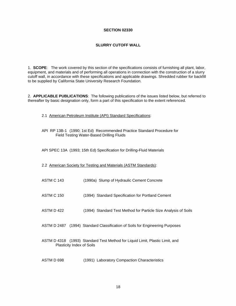
SECTION 02330
SLURRY CUTOFF WALL
1. SCOPE: The work covered by this section of the specifications consists of furnishing all plant, labor, equipment, and materials and of performing all operations in connection with the construction of a slurry cutoff wall, in accordance with these specifications and applicable drawings. Shredded rubber for backfill to be supplied by California State University Research Foundation.
2. APPLICABLE PUBLICATIONS: The following publications of the issues listed below, but referred to thereafter by basic designation only, form a part of this specification to the extent referenced.
2.1 American Petroleum Institute (API) Standard Specifications:
API RP 13B-1 (1990; 1st Ed) Recommended Practice Standard Procedure for Field Testing Water-Based Drilling Fluids
API SPEC 13A (1993; 15th Ed) Specification for Drilling-Fluid Materials
2.2 American Society for Testing and Materials (ASTM Standards):
ASTM C 143 (1990a) Slump of Hydraulic Cement Concrete
ASTM C 150 (1994) Standard Specification for Portland Cement
ASTM D 422 (1994) Standard Test Method for Particle Size Analysis of Soils
ASTM D 2487 (1994) Standard Classification of Soils for Engineering Purposes
ASTM D 4318 (1993) Standard Test Method for Liquid Limit, Plastic Limit, and Plasticity Index of Soils
ASTM D 698 (1991) Laboratory Compaction Characteristics
18
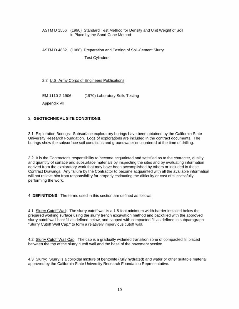
ASTM D 1556 (1990) Standard Test Method for Density and Unit Weight of Soil in Place by the Sand-Cone Method
ASTM D 4832 (1988) Preparation and Testing of Soil-Cement Slurry
Test Cylinders
2.3 U.S. Army Corps of Engineers Publications:
EM 1110-2-1906 (1970) Laboratory Soils Testing
Appendix VII
3. GEOTECHNICAL SITE CONDITIONS:
3.1 Exploration Borings: Subsurface exploratory borings have been obtained by the California State University Research Foundation. Logs of explorations are included in the contract documents. The borings show the subsurface soil conditions and groundwater encountered at the time of drilling.
3.2 It is the Contractor's responsibility to become acquainted and satisfied as to the character, quality, and quantity of surface and subsurface materials by inspecting the sites and by evaluating information derived from the exploratory work that may have been accomplished by others or included in these Contract Drawings. Any failure by the Contractor to become acquainted with all the available information will not relieve him from responsibility for properly estimating the difficulty or cost of successfully performing the work.
4 DEFINITIONS: The terms used in this section are defined as follows;
4.1 Slurry Cutoff Wall: The slurry cutoff wall is a 1.5-foot minimum width barrier installed below the prepared working surface using the slurry trench excavation method and backfilled with the approved slurry cutoff wall backfill as defined below, and capped with compacted fill as defined in subparagraph "Slurry Cutoff Wall Cap," to form a relatively impervious cutoff wall.
4.2 Slurry Cutoff Wall Cap: The cap is a gradually widened transition zone of compacted fill placed between the top of the slurry cutoff wall and the base of the pavement section.
4.3 Slurry: Slurry is a colloidal mixture of bentonite (fully hydrated) and water or other suitable material approved by the California State University Research Foundation Representative.
19
20
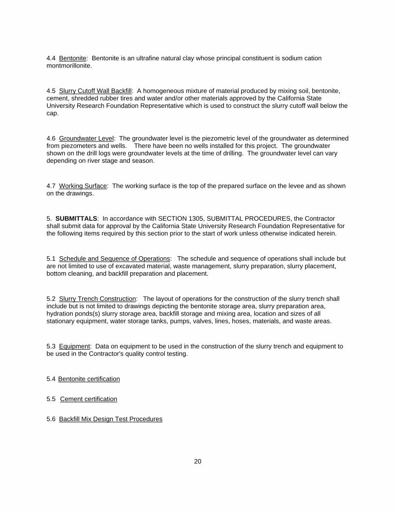
4.4 Bentonite: Bentonite is an ultrafine natural clay whose principal constituent is sodium cation montmorillonite.
4.5 Slurry Cutoff Wall Backfill: A homogeneous mixture of material produced by mixing soil, bentonite, cement, shredded rubber tires and water and/or other materials approved by the California State University Research Foundation Representative which is used to construct the slurry cutoff wall below the cap.
4.6 Groundwater Level: The groundwater level is the piezometric level of the groundwater as determined from piezometers and wells. There have been no wells installed for this project. The groundwater shown on the drill logs were groundwater levels at the time of drilling. The groundwater level can vary depending on river stage and season.
4.7 Working Surface: The working surface is the top of the prepared surface on the levee and as shown on the drawings.
5. SUBMITTALS: In accordance with SECTION 1305, SUBMITTAL PROCEDURES, the Contractor shall submit data for approval by the California State University Research Foundation Representative for the following items required by this section prior to the start of work unless otherwise indicated herein.
5.1 Schedule and Sequence of Operations: The schedule and sequence of operations shall include but are not limited to use of excavated material, waste management, slurry preparation, slurry placement, bottom cleaning, and backfill preparation and placement.
5.2 Slurry Trench Construction: The layout of operations for the construction of the slurry trench shall include but is not limited to drawings depicting the bentonite storage area, slurry preparation area, hydration ponds(s) slurry storage area, backfill storage and mixing area, location and sizes of all stationary equipment, water storage tanks, pumps, valves, lines, hoses, materials, and waste areas.
5.3 Equipment: Data on equipment to be used in the construction of the slurry trench and equipment to be used in the Contractor's quality control testing.
5.4 Bentonite certification
5.5 Cement certification
5.6 Backfill Mix Design Test Procedures
21
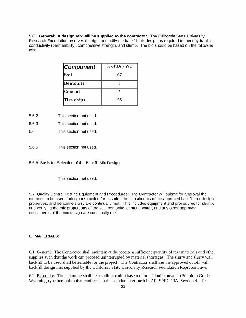
5.6.1 General: A design mix will be supplied to the contractor. The California State University Research Foundation reserves the right to modify the backfill mix design as required to meet hydraulic conductivity (permeability), compressive strength, and slump. The bid should be based on the following mix:
Component % of Dry Wt.
Soil 67
Bentonite 3
Cement 5
Tire chips 25
5.6.2 This section not used.
5.6.3 This section not used.
5.6. This section not used.
5.6.5 This section not used.
5.6.6 Basis for Selection of the Backfill Mix Design:
This section not used.
5.7 Quality Control Testing Equipment and Procedures: The Contractor will submit for approval the methods to be used during construction for assuring the constituents of the approved backfill mix design properties, and bentonite slurry are continually met. This includes equipment and procedures for slump, and verifying the mix proportions of the soil, bentonite, cement, water, and any other approved constituents of the mix design are continually met.
6. MATERIALS:
6.1 General: The Contractor shall maintain at the jobsite a sufficient quantity of raw materials and other supplies such that the work can proceed uninterrupted by material shortages. The slurry and slurry wall backfill to be used shall be suitable for the project. The Contractor shall use the approved cutoff wall backfill design mix supplied by the California State University Research Foundation Representative.
6.2 Bentonite: The bentonite shall be a sodium cation base montmorillonite powder (Premium Grade Wyoming-type bentonite) that conforms to the standards set forth in API SPEC 13A, Section 4. The
22
Contractor shall furnish to the California State University Research Foundation Representative a certificate of compliance and a copy of the test reports from the bentonite manufacturer for each lot of bentonite shipped to the site stating that the bentonite complies with all applicable standards. No bentonite from the bentonite manufacturer shall be used prior to acceptance by the California State University Research Foundation Representative. All bentonite will be subject to inspection, sampling, and verification of quality by testing under the supervision of the California State University Research Foundation. Bentonite not meeting the specifications shall be promptly removed from the site and replaced with bentonite conforming to specification requirements at the Contractor's expense. Bentonite shall be protected from moisture during transit and storage.
6.3 Cement: Cement shall be Portland Cement Type I or Type II (per ASTM C 150). A written certification specifying cement quality shall be provided by the cement supplier and retained by the Contractor.
6.4 Water: The Contractor shall supply all water required for mixing with bentonite to produce slurry and slurry backfill. The water shall be clean, fresh, and comply with the standards set below:
a. A pH equal to 7.0 plus or minus 1.0.
b. Total dissolved solids not greater than 500 parts per million.
c. Oil, organics, acids, alkali, or other deleterious substances not greater than 50 parts per million each.
d. Hardness less than or equal to 50 ppm (Recommendation Only). The canal at the work site is an acceptable source of water.
6.5 Admixtures: In the event the Contractor uses any additional admixture, it shall be subject to approval of the California State University Research Foundation Representative and the Contractor shall have on file a written statement as to the use of any such admixture, it's effect on the slurry, its long-term stability, and its effect on the environment. Admixtures of the type used in the control of oil field drilling mud such as thinners, dispersants, and flocculants may be used to control standard properties of the slurry such as apparent viscosity and filtration characteristics subject to the approval of the California State University Research Foundation Representative. Peptizing or bulking agents shall not be mixed with the slurry.
6.6 Shredded Rubber Tire: Shredded Rubber tire will be supplied by the California State University Research Foundation. The approximate size of the tire chips will be capable of passing a 2” sieve. The tire chips will be delivered to the jobsite staging area by the tire processor . The haul vehicle will be an end dump truck.
6.7 Bentonite Slurry: The bentonite slurry for supporting the sides of the trench and that mixed with the backfill shall consist of a stable colloidal suspension of powdered, premium-grade natural bentonite in water. It is the responsibility of the Contractor that the slurry meets the necessary properties. The properties of the slurry used in all construction sequences shall be determined in accordance with the testing procedures described in API RP 13B-1 and shall conform to the following requirements:

23
6.7.1 Initial Bentonite Slurry Mixture: At the time of introducing bentonite slurry into the trench excavation, the slurry mixture shall have a minimum apparent viscosity of 40 seconds as measured by the Marsh funnel. The slurry density shall be a minimum of 64 pounds per cubic foot. The water loss shall not be greater than 20 cubic centimeters in 30 minutes as measured by a filter press at 100 psi. Mixture adjustments shall conform to the requirements in paragraph "ADDITIONAL BENTONITE."
6.7.2 Trench Bentonite Slurry Mixture: The minimum apparent viscosity of the bentonite slurry mixture in the trench at any time shall be 40 seconds as measured by the Marsh funnel. The density of the slurry in the trench at any level shall be between 64 and 85 pounds per cubic foot. The water loss shall not be greater than 20 cubic centimeters in 30 minutes as measured by the filter press at 100 psi. Mixture adjustment shall conform to the requirements in paragraph "ADDITIONAL BENTONITE."
6.7.3 Additional Bentonite: If directed by the California State University Research Foundation Representative, the Contractor shall thicken the slurry to a more viscous condition than the limits specified above. The Contractor shall use additional bentonite, as directed.
6.8 Soil: Soils obtained from the cutoff wall construction, imported material, or combination thereof, for use in the slurry cutoff wall backfill, shall contain no material sizes larger than 3 inches in diameter and shall be free of roots, debris, and other deleterious material that may adversely affect the properties of the backfill. The Contractor is responsible for changes in the chemistry of soils used in the slurry wall cutoff construction and its effect on the desired properties of the backfill.
6.9 Slurry Wall Backfill: The slurry wall backfill mix shall confrom to the design as stated in Section 5.6.1. However the California State University Research Foundation and contractor will cooperate in modifying the mix, if necessary, to improve workability. The Intent of the Research Foundation is to verify the viability of a mix incorporating waste tire chips. The goal is for the mix to meet permeability and strength requirements while maximizing the quantity of tire chips used. All backfill shall be free of roots and other deleterious materials.
6.9.1 Testing: The backfill mix will be sampled at least every 300 ft. of wall or when any changes are made to the backfill mixing operation. The California State University Research Foundation will be responsible for all testing of the backfill mix. Plastic molds shall be used to cast the mix specimens. The molds will be twelve-inch diameter by twelve -inch long test cylinders for permeability tests and twelve-inch diameter by twenty-four-inch long test cylinders for strength tests. The wet samples will be poured into the molds and rodded or vibrated to remove trapped air pockets and then sealed. The specimens will be stored in a constant temperature, damp environment, positioned on porous stones with filter paper to allow for drainage during the curing period, until tested or otherwise directed by the California State University Research Foundation Representative.
24
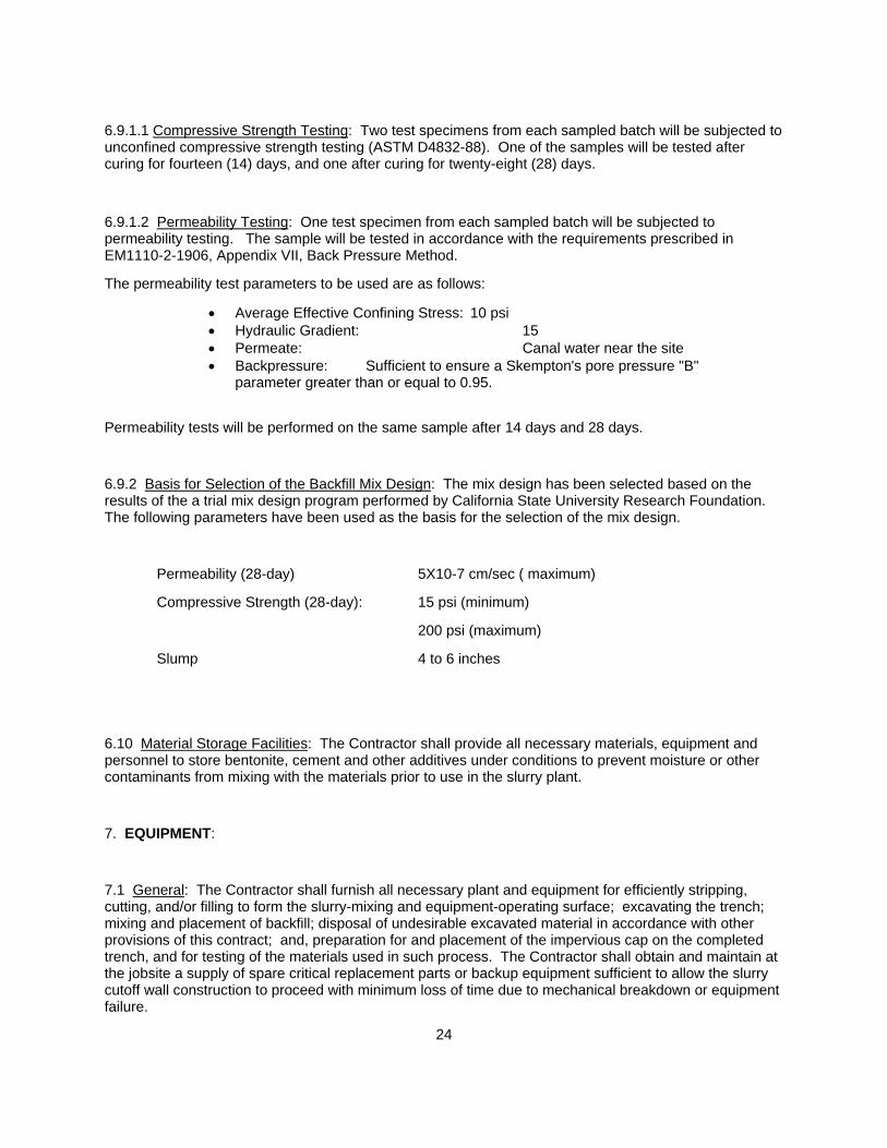
6.9.1.1 Compressive Strength Testing: Two test specimens from each sampled batch will be subjected to unconfined compressive strength testing (ASTM D4832-88). One of the samples will be tested after curing for fourteen (14) days, and one after curing for twenty-eight (28) days.
6.9.1.2 Permeability Testing: One test specimen from each sampled batch will be subjected to permeability testing. The sample will be tested in accordance with the requirements prescribed in EM1110-2-1906, Appendix VII, Back Pressure Method.
The permeability test parameters to be used are as follows:
• Average Effective Confining Stress: 10 psi • Hydraulic Gradient: 15 • Permeate: Canal water near the site • Backpressure: Sufficient to ensure a Skempton's pore pressure "B"
parameter greater than or equal to 0.95.
Permeability tests will be performed on the same sample after 14 days and 28 days.
6.9.2 Basis for Selection of the Backfill Mix Design: The mix design has been selected based on the results of the a trial mix design program performed by California State University Research Foundation. The following parameters have been used as the basis for the selection of the mix design.
Permeability (28-day) 5X10⁻⁷ cm/sec ( maximum)
Compressive Strength (28-day): 15 psi (minimum)
200 psi (maximum)
Slump 4 to 6 inches
6.10 Material Storage Facilities: The Contractor shall provide all necessary materials, equipment and personnel to store bentonite, cement and other additives under conditions to prevent moisture or other contaminants from mixing with the materials prior to use in the slurry plant.
7. EQUIPMENT:
7.1 General: The Contractor shall furnish all necessary plant and equipment for efficiently stripping, cutting, and/or filling to form the slurry-mixing and equipment-operating surface; excavating the trench; mixing and placement of backfill; disposal of undesirable excavated material in accordance with other provisions of this contract; and, preparation for and placement of the impervious cap on the completed trench, and for testing of the materials used in such process. The Contractor shall obtain and maintain at the jobsite a supply of spare critical replacement parts or backup equipment sufficient to allow the slurry cutoff wall construction to proceed with minimum loss of time due to mechanical breakdown or equipment failure.
25
7.2 Equipment Weight, Speed, and Width: Weight of equipment to be used on the levee crown shall be limited to a maximum gross loaded axle weight of 16,000 pounds, and a maximum track vehicle weight of 2,500 pounds per square foot. The maximum operating speed of all equipment used on the levee crown roads shall be 15 mph. The maximum overall width of equipment used on the levee shall be limited to 18 feet.
7.3 Cutoff Wall Construction: Trench excavation equipment for excavating the slurry trench shall be any type of earth moving machinery capable of performing the indicated work on the drawings and/or as specified herein. The equipment shall be that which reduces live-load surcharge to a level that will produce no significant contribution to the instability of the trench. Regardless of the equipment type used, it shall be capable of excavating to the required depth and width of the trench in a single pass of the excavating equipment. If a dragline bucket is used, it shall be a heavy duty model with no protrusions along the sides of the bucket for drag or hoist chains extending beyond the limits of the cutter teeth.
7.4 Mixing and Delivering Slurry: Slurry mixing and placing equipment will be approved by the California State University Research Foundation Representative. The slurry mixing plant shall be a colloidal batch or continuous mixing plant. It shall include the necessary equipment, including a mixer capable of producing a stable colloidal suspension of slurry or other mix combinations approved by the California State University Research Foundation Representative. It shall include pumps, valves, hoses, supply lines, tools, and other equipment and materials required to adequately supply slurry to the slurry trench. Tanks for storage of hydrated slurry shall be mechanically or hydraulically agitated.
7.5 Mixing and Placing Backfill: The equipment used for the mixing and placing of the backfill material, including but not limited to bulldozers, disks, harrows, motor patrols, pugmills and haul trucks shall be capable of mixing backfill materials into a homogeneous mixture conforming to the contract requirements and be suitable for placement of the backfill material in the trench as specified herein. Initial placement of backfill on the trench bottom shall be by clamshell or other approved method and shall prevent free fall, segregation, and entrapment of slurry.
7.6 Retaining Berms: Suitable grading and earth-moving equipment shall be available for preparing the work area for slurry cutoff wall installation including equipment for the construction of slurry spill retainment berms or ditches.
7.7 Hauling Equipment: Hauling equipment shall consist of pneumatic-tired vehicles having dump bodies suitable for dumping.
7.8 Cleaning of Slurry: Slurry cleaning equipment shall include but not be limited to a vibrating shaker screen, centrifugal sand separator, and/or stilling ponds.
26
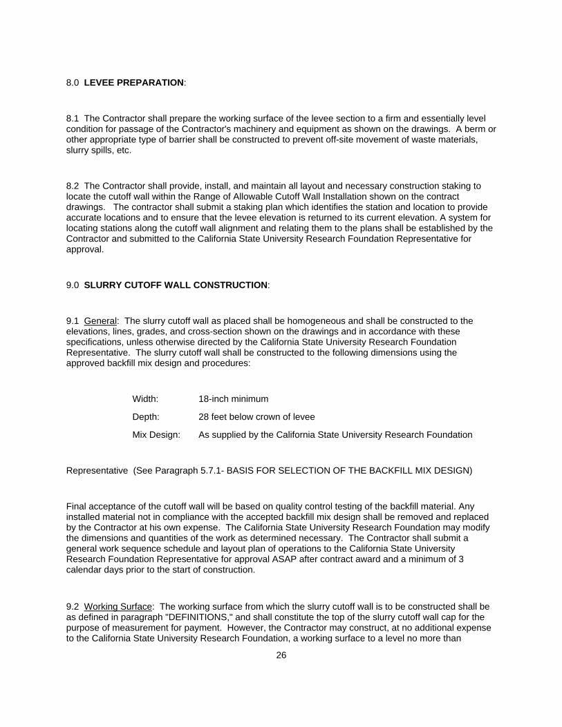
8.0 LEVEE PREPARATION:
8.1 The Contractor shall prepare the working surface of the levee section to a firm and essentially level condition for passage of the Contractor's machinery and equipment as shown on the drawings. A berm or other appropriate type of barrier shall be constructed to prevent off-site movement of waste materials, slurry spills, etc.
8.2 The Contractor shall provide, install, and maintain all layout and necessary construction staking to locate the cutoff wall within the Range of Allowable Cutoff Wall Installation shown on the contract drawings. The contractor shall submit a staking plan which identifies the station and location to provide accurate locations and to ensure that the levee elevation is returned to its current elevation. A system for locating stations along the cutoff wall alignment and relating them to the plans shall be established by the Contractor and submitted to the California State University Research Foundation Representative for approval.
9.0 SLURRY CUTOFF WALL CONSTRUCTION:
9.1 General: The slurry cutoff wall as placed shall be homogeneous and shall be constructed to the elevations, lines, grades, and cross-section shown on the drawings and in accordance with these specifications, unless otherwise directed by the California State University Research Foundation Representative. The slurry cutoff wall shall be constructed to the following dimensions using the approved backfill mix design and procedures:
Width: 18-inch minimum
Depth: 28 feet below crown of levee
Mix Design: As supplied by the California State University Research Foundation
Representative (See Paragraph 5.7.1- BASIS FOR SELECTION OF THE BACKFILL MIX DESIGN)
Final acceptance of the cutoff wall will be based on quality control testing of the backfill material. Any installed material not in compliance with the accepted backfill mix design shall be removed and replaced by the Contractor at his own expense. The California State University Research Foundation may modify the dimensions and quantities of the work as determined necessary. The Contractor shall submit a general work sequence schedule and layout plan of operations to the California State University Research Foundation Representative for approval ASAP after contract award and a minimum of 3 calendar days prior to the start of construction.
9.2 Working Surface: The working surface from which the slurry cutoff wall is to be constructed shall be as defined in paragraph "DEFINITIONS," and shall constitute the top of the slurry cutoff wall cap for the purpose of measurement for payment. However, the Contractor may construct, at no additional expense to the California State University Research Foundation, a working surface to a level no more than
27
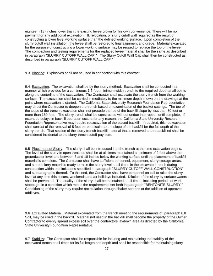
eighteen (18) inches lower than the existing levee crown for his own convenience. There will be no payment for any additional excavation, fill, relocation, or slurry cutoff wall required as the result of constructing a lower level working surface than the defined working surface. Upon completion of the slurry cutoff wall installation, the levee shall be restored to final alignment and grade. Material excavated for the purpose of constructing a lower working surface may be reused to replace the top of the levee. The compaction and testing requirements for the replaced levee material shall be the same as described in paragraph "SLURRY CUTOFF WALL CAP." The Slurry Cutoff Wall Cap shall then be constructed as described in paragraph "SLURRY CUTOFF WALL CAP."
9.3 Blasting: Explosives shall not be used in connection with this contract.
9.4 Excavation: The excavation shall be by the slurry method. Excavation shall be conducted in a manner which provides for a continuous 1.5-foot minimum width trench to the required depth at all points along the centerline of the excavation. The Contractor shall excavate the slurry trench from the working surface. The excavation shall be carried immediately to the minimum depth shown on the drawings at the point where excavation is started. The California State University Research Foundation Representative may direct the Contractor to deepen the trench based on examination of the bucket cuttings. The toe of the slope of the trench excavation shall not precede the toe of the backfill slope by less than 50 feet or more than 150 feet. The slurry trench shall be constructed without undue interruption until complete. If extended delays in backfill operation occurs for any reason, the California State University Research Foundation Representative may require reexcavation of the placed backfill. If required, this reexcavation shall consist of the removal of 5 feet perpendicular to the slope of the backfill for the full depth of the slurry trench. That section of the slurry trench backfill material that is removed and rebackfilled shall be considered incidental to the slurry trench cutoff pay item.
9.5 Placement of Slurry: The slurry shall be introduced into the trench at the time excavation begins. The level of the slurry in open trenches shall be at all times maintained a minimum of 2 feet above the groundwater level and between 6 and 18 inches below the working surface until the placement of backfill material is complete. The Contractor shall have sufficient personnel, equipment, slurry storage areas, and stored slurry materials ready to raise the slurry level at all times in the excavated trench during construction within the limitations specified in paragraph "SLURRY CUTOFF WALL CONSTRUCTION" and subparagraphs thereof. To this end, the Contractor shall have personnel on call to raise the slurry level at any time this occurs, weekends and /or holidays included. Dilution of the slurry by surface waters shall be prevented. The quality of the slurry shall be maintained at all times, including periods of work stoppage, in a condition which meets the requirements set forth in paragraph "BENTONITE SLURRY." Conditioning of the slurry may require recirculation through shaker screens or the addition of approved additives.
9.6 Excavated Material: Material excavated from the trench meeting the requirements of paragraph 6.8 Soil, may be used in the backfill. Material not used in the backfill shall become the property of the Owner. Contractor to evenly spread excess soil over the contractors laydown area as directed by the California State University Foundation Representative.
9.7 Stability: The Contractor shall be responsible for insuring and maintaining the stability of the excavated trench at all times for its full length and depth and shall be responsible for maintaining slurry

28
densities and levels within specified limits. The Contractor shall control surcharges from all excavation and backfilling equipment, waste, berm construction, backfill stockpiles, and any other loading situations that may affect trench stability. It is the Contractor's sole responsibility to ensure that the mixing of backfill and any stockpiles do not affect the open trench stability. In the event of failure of the trench walls prior to completion of backfilling, the Contractor shall at his expense reexcavate the trench and remove all material displaced into the trench and take corrective action to prevent further deterioration.
10. BACKFILLING:
10.1 Mixing Areas: Areas for mixing of backfill, preparing compacted fill for the slurry cutoff wall cap, and other operations shall be located within designated staging areas shown on the contract drawings or within areas approved by the California State University Research Foundation Representative. All mixing areas shall be cleaned up and restored upon completion of the work in accordance with paragraph "CLEANUP."
10.2 Mixing: Stockpiled material generated during slurry cutoff wall installation and/or material from borrow or commercial sources shall be mixed and blended by approved methods. The backfill material shall be thoroughly mixed into a homogeneous mass, free from large lumps or pockets of fines, sand, or gravel. Occasional lumps of up to four (4) inches in their largest dimension will be permitted. The backfill material shall have a consistency as approved by the California State University Research Foundation Representative. The backfill material, just prior to placement in the trench, shall have a consistency to provide a slump of from 4 to 6 inches per ASTM C 143 . Any damage to the slurry cutoff wall as a result of operating equipment near the wall or for other reasons shall be repaired or restored by the Contractor at no additional cost to the California State University Research Foundation.
10.3 Placement: The backfill material shall be placed in the excavated trench in such a manner that no pockets of slurry are trapped in the completed slurry trench. The Contractor shall backfill continuously from the beginning of the trench in the direction of the excavation to the end of the trench. Placing operations shall proceed in such a fashion that the top of the backfill below the surface of the slurry shall follow a reasonably smooth grade and shall not have hollows which may trap pockets of slurry during subsequent backfilling. To this end, the face of the backfill below the surface of the slurry may require rodding, and the Contractor shall have such equipment available at the job site. Free dropping of backfill material through the slurry will not be permitted. Initial backfill shall be placed by lowering it to the bottom of the trench with crane and clamshell bucket until the surface of the backfill rises above the surface of the slurry trench at the end of the trench. Backfill shall then be placed in such a manner that the backfill enters the trench by sliding down the forward face of the previously placed backfill. To accomplish this, the Contractor shall backfill from the initial backfill toward the opposite end of the trench. Backfilling operations shall proceed in such a manner that the slope of the initial backfill will be maintained. The new backfill material will be allowed to slide down the slope of the previously placed backfill and shall be placed in such a manner that pockets of slurry will not be trapped during the backfilling. This remaining backfill may be accomplished by the use of bulldozer or other approved equipment and in such a manner that the backfill below the slurry surface will be pushed along the trench.
10.4 Mixing and Placing During Cold Weather: No mixing or placing of the backfill shall be performed when the air temperature is below 32 degrees F. Frozen backfill shall not be placed in the slurry trench.
29
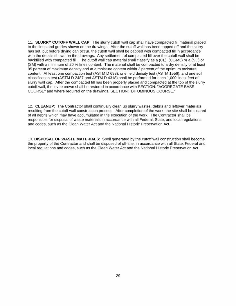
11. SLURRY CUTOFF WALL CAP: The slurry cutoff wall cap shall have compacted fill material placed to the lines and grades shown on the drawings. After the cutoff wall has been topped off and the slurry has set, but before drying can occur, the cutoff wall shall be capped with compacted fill in accordance with the details shown on the drawings. Any settlement of compacted fill over the cutoff wall shall be backfilled with compacted fill. The cutoff wall cap material shall classify as a (CL), (CL-ML) or a (SC) or (SM) with a minimum of 20 % fines content. The material shall be compacted to a dry density of at least 95 percent of maximum density and at a moisture content within 2 percent of the optimum moisture content. At least one compaction test (ASTM D 698), one field density test (ASTM 1556), and one soil classification test (ASTM D 2487 and ASTM D 4318) shall be performed for each 1,000 lineal feet of slurry wall cap. After the compacted fill has been properly placed and compacted at the top of the slurry cutoff wall, the levee crown shall be restored in accordance with SECTION: "AGGREGATE BASE COURSE" and where required on the drawings, SECTION: "BITUMINOUS COURSE."
12. CLEANUP: The Contractor shall continually clean up slurry wastes, debris and leftover materials resulting from the cutoff wall construction process. After completion of the work, the site shall be cleared of all debris which may have accumulated in the execution of the work. The Contractor shall be responsible for disposal of waste materials in accordance with all Federal, State, and local regulations and codes, such as the Clean Water Act and the National Historic Preservation Act.
13. DISPOSAL OF WASTE MATERIALS: Spoil generated by the cutoff wall construction shall become the property of the Contractor and shall be disposed of off-site, in accordance with all State, Federal and local regulations and codes, such as the Clean Water Act and the National Historic Preservation Act.
30
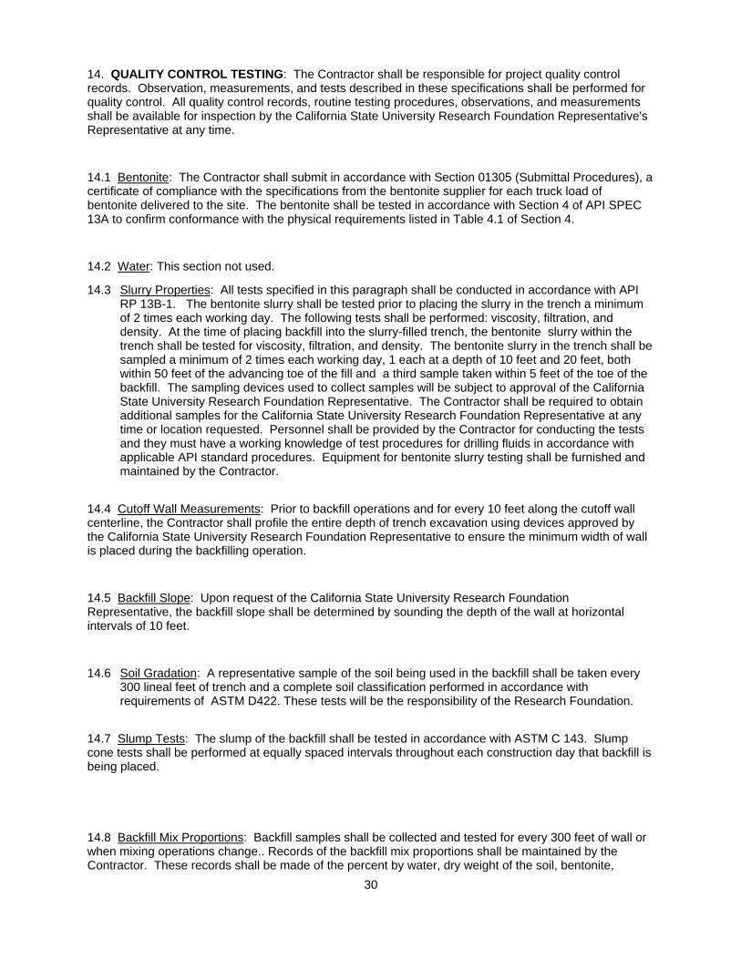
14. QUALITY CONTROL TESTING: The Contractor shall be responsible for project quality control records. Observation, measurements, and tests described in these specifications shall be performed for quality control. All quality control records, routine testing procedures, observations, and measurements shall be available for inspection by the California State University Research Foundation Representative's Representative at any time.
14.1 Bentonite: The Contractor shall submit in accordance with Section 01305 (Submittal Procedures), a certificate of compliance with the specifications from the bentonite supplier for each truck load of bentonite delivered to the site. The bentonite shall be tested in accordance with Section 4 of API SPEC 13A to confirm conformance with the physical requirements listed in Table 4.1 of Section 4.
14.2 Water: This section not used.
14.3 Slurry Properties: All tests specified in this paragraph shall be conducted in accordance with API RP 13B-1. The bentonite slurry shall be tested prior to placing the slurry in the trench a minimum of 2 times each working day. The following tests shall be performed: viscosity, filtration, and density. At the time of placing backfill into the slurry-filled trench, the bentonite slurry within the trench shall be tested for viscosity, filtration, and density. The bentonite slurry in the trench shall be sampled a minimum of 2 times each working day, 1 each at a depth of 10 feet and 20 feet, both within 50 feet of the advancing toe of the fill and a third sample taken within 5 feet of the toe of the backfill. The sampling devices used to collect samples will be subject to approval of the California State University Research Foundation Representative. The Contractor shall be required to obtain additional samples for the California State University Research Foundation Representative at any time or location requested. Personnel shall be provided by the Contractor for conducting the tests and they must have a working knowledge of test procedures for drilling fluids in accordance with applicable API standard procedures. Equipment for bentonite slurry testing shall be furnished and maintained by the Contractor.
14.4 Cutoff Wall Measurements: Prior to backfill operations and for every 10 feet along the cutoff wall centerline, the Contractor shall profile the entire depth of trench excavation using devices approved by the California State University Research Foundation Representative to ensure the minimum width of wall is placed during the backfilling operation.
14.5 Backfill Slope: Upon request of the California State University Research Foundation Representative, the backfill slope shall be determined by sounding the depth of the wall at horizontal intervals of 10 feet.
14.6 Soil Gradation: A representative sample of the soil being used in the backfill shall be taken every 300 lineal feet of trench and a complete soil classification performed in accordance with requirements of ASTM D422. These tests will be the responsibility of the Research Foundation.
14.7 Slump Tests: The slump of the backfill shall be tested in accordance with ASTM C 143. Slump cone tests shall be performed at equally spaced intervals throughout each construction day that backfill is being placed.
14.8 Backfill Mix Proportions: Backfill samples shall be collected and tested for every 300 feet of wall or when mixing operations change.. Records of the backfill mix proportions shall be maintained by the Contractor. These records shall be made of the percent by water, dry weight of the soil, bentonite,
31
cement, and any other approved additives utilized. Any approved adjustments in the bentonite mix shall also be recorded.
15. RECORDS: Records shall be maintained by the Contractor for all testing, measurements, and inspections performed to ascertain that the cutoff wall construction meets the specifications. Required reports, records, and documentation shall be furnished to the California State University Research Foundation Representative daily. The Contractor's required records are outlined below.
15.1 As-Built Profile: An as-built profile of the trench bottom, backfill slope including descriptions of materials encountered in the trench bottom shall be continuously maintained by the Contractor. This profile shall indicate extent of excavation and the backfill profile at the end of each work day, as determined from the soundings. The Contractor shall furnish records of all observations, measurements, and tests performed, identified with the location and time of testing. These records shall be furnished no later than 24 hours after the tests, measurements, and/or observations were made.
15.2 Results: The results of all construction control testing required in these specifications, including water tests, slurry tests, backfill tests, and depth of soundings shall be furnished by the Contractor. The Contractor shall furnish records of all observations, measurements, and tests performed, identified with the location and time of testing. These records shall be furnished no later than 24 hours after the tests, measurements, and/or observations were made.
15.3 Construction Log: The Contractor shall maintain a construction log of daily activities which shall include delays encountered during construction, causes of delays, locations of affected areas, and extent of delays. The log shall also record unusual conditions or problems encountered, and the dispositions made. The Construction log is to be submitted to the California State University Research Foundation Representative at the end of each shift.
16. QUALITY ASSURANCE: The California State University Research Foundation may collect and perform quality assurance testing on the bentonite slurry and slurry wall backfill materials. The California State University Research Foundation testing will in no way relieve the Contractor of the responsibility of performing tests necessary to meet the construction requirements. All routine testing procedures being conducted by the Contractor shall be available for inspection by the California State University Research Foundation Representative at any time.
17. MEASUREMENT: Measurement for Slurry Cutoff Wall, shall be based on the area in square feet of wall measured in a vertical plane through the centerline of the slurry cutoff wall within the boundaries established by the working surface as defined in DEFINITIONS, the bottom of the slurry cutoff wall and vertical lines at each end of the slurry cutoff wall. Measurement shall be based on surveys and measurements taken at the site as directed and approved by the California State University Research Foundation Representative. Payment shall be made on the basis of a slurry wall constructed to the depth indicated on the drawings unless excavation to a greater depth is directed by the California State University Research Foundation Representative.
18. PAYMENT: Payment for slurry cutoff wall measured as specified herein before shall be made at the contract price per square foot. Such price shall include all costs of levee preparation, slurry cutoff wall installation, stockpiling or spoiling materials generated during the slurry cutoff wall installation, obtaining backfill materials from commercial sources, mixing, blending, placing the slurry cutoff wall backfill and slurry cutoff wall cap, and all other items incidental to the construction of the construction and completion of the slurry cutoff wall. No separate payment will be made for materials including bentonite, cement, additives, soil, equipment and mixing, handling and cleaning the slurry, diking around the open trench,

32
and overtime during continuous operations, cleanup, assistance in the collection and maintenance of records and quality control testing; such items being included in the price of the slurry cutoff wall. Final acceptance of the slurry cutoff wall will be based on meeting all the requirements for the slurry wall dimensions, bentonite slurry mix, and the approved mix design or any California State University Research Foundation Representative approved modifications to the backfill mix design.

33
Appendix C Monitoring Water Level Charts
34
6 HOURS AFTER FILLING CANAL
0
0.25
0.5
0.75
1
1.25
1.5
1.75
2
W-1 W-2 W-3 W-4 W-5 W-6 W-7 W-8 W-9
WELL
WA
TER
ELE
VATI
ON
INC
REA
SE (F
T)
12 HOURS AFTER FILLING CANAL
0
0.25
0.5
0.75
1
1.25
1.5
1.75
2
W-1 W-2 W-3 W-4 W-5 W-6 W-7 W-8 W-9
WELL NUMBER
WA
TER
ELE
VATI
ON
INC
REA
SE (F
T)
35
24 HOURS AFTER FILLING CANAL
0
0.25
0.5
0.75
1
1.25
1.5
1.75
2
W-1 W-2 W-3 W-4 W-5 W-6 W-7 W-8 W-9
WELL NUMBER
WA
TER
ELE
VATI
ON
INC
REA
SE (F
T)
36
Appendix D Daily Construction Reports
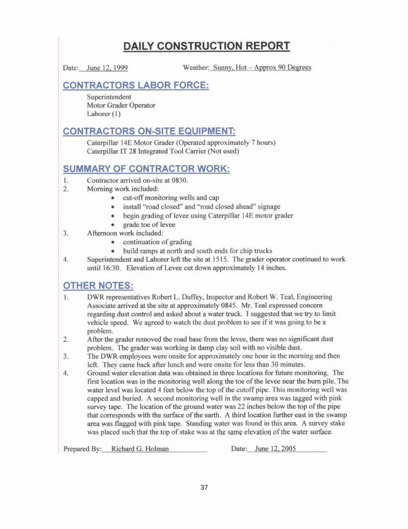
37
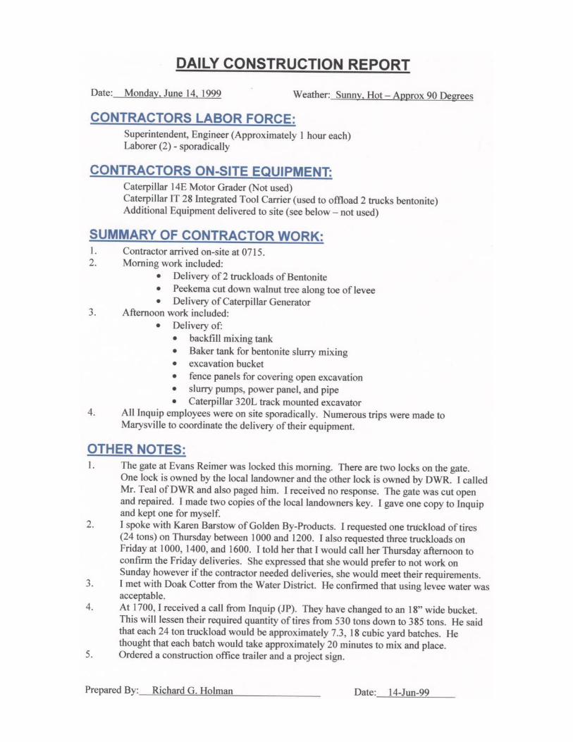
38
39
40

41
42
43
44

45
46
47
48
49
50
51
52

53
54
55

56
57
58
59
60

61
62
63

64
65

66
67
68
69

70

71
72

73
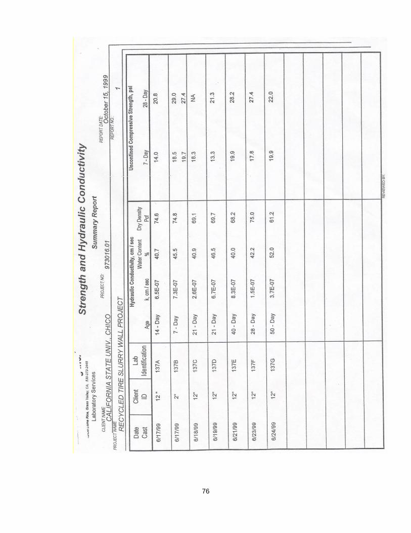
Appendix E Laboratory Test Results

74
75
76