
The Experiences of the world’s biggest Recovery...
12
1(12) The Experiences of the world’s biggest Recovery Boiler in Yang Pu at Hainan Jinhai Pulp & Paper Co. Kari Haaga Markku Laitinen Kvaerner Power Oy The site in 2005
Transcript of The Experiences of the world’s biggest Recovery...

1(12)
The Experiences of the world’s biggest Recovery Boiler in Yang Pu at Hainan
Jinhai Pulp & Paper Co.
Kari Haaga Markku Laitinen
Kvaerner Power Oy
The site in 2005
2(12)
1. THE EXPERIENCES OF WORLD’S BIGGEST RECOVERY BOILER 1.1 Abstract The chemical wood pulp production has during the last decades on an average grown with 2-3 mill. ton/annum. This capacity increase consists of new installations, including greenfield mills and capacity increases on existing recovery boilers. The main part of the new projects is hardwood lines operating on planted eucalyptus. The new recovery boilers are characterised by high capacity, environment-friendly process solutions, low air emissions and handling and burning of both diluted and concentrated odorous gases. New developments in technology made it possible to take advantage of the economy of scale when building those new pulping lines. Obviously the recovery boilers had to grow in size in order to meet the production capacity in the large new single line pulp mills. Excellent process and mechanical experiences from XL size recovery boilers have smoothened the way to XXL size recovery boilers. Jinhai recovery boiler is the largest recovery boiler in the world and its design is based on proven features of XL size recovery boilers. The plant design was made in PDMS, which gives a complete 3D model of recovery boiler including all details. The PDMS model is also of great help in the erection phase. Other sophisticated engineering tools like CFD (Computational Fluid Dynamics), Fouling Advisor RBD (Recovery Boiler Designer) were also used when Jinhai boiler was on the design phase. World’s biggest boiler consists of the latest design from environmental point of view; all NCG (Non condensable gas) gases are burnt in recovery boiler. Dissolving tank and mixing tank vent gases are burnt at tertiary air level, CNCG (Concentrated Non Condensable Gas) burner is located at secondary air level and DNCG (Diluted Non Condensable Gas) gases are introduced to the high secondary air system. Boiler is also designed for high dry solids firing of 80% black liquor dry solids content in virgin black liquor. The paper will also cover some mechanical features of Jinhai boiler like material selection of furnace etc. Also some operation parameters after one and a half years in operation will be presented. 1.2 Hainan Jinhai Pulp & Paper Co. World’s biggest single line pulp mill started up in November 2004 at Hainan Jinhai Pulp & Paper mill in China. The mill is located in the northern part of Hainan island at the south end of China. The capital of the Hainan is Haikou City and it is located in the northern part of island. The mill is located about 200 km to the west from Haikou in the harbour town Yang Pu where are about 10.000 inhabitants.
3(12)
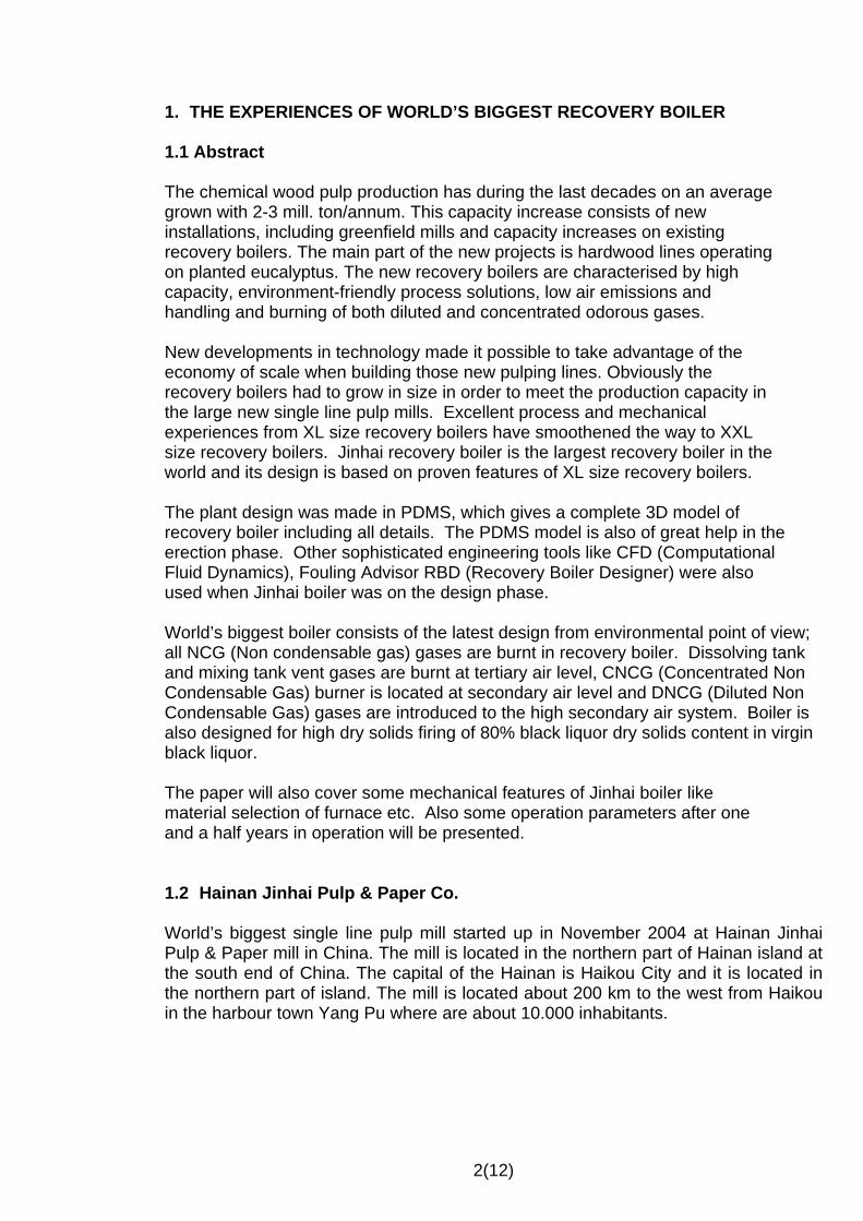
Figure 1. Hainan Jinhai Pulp & Paper Co., Ltd
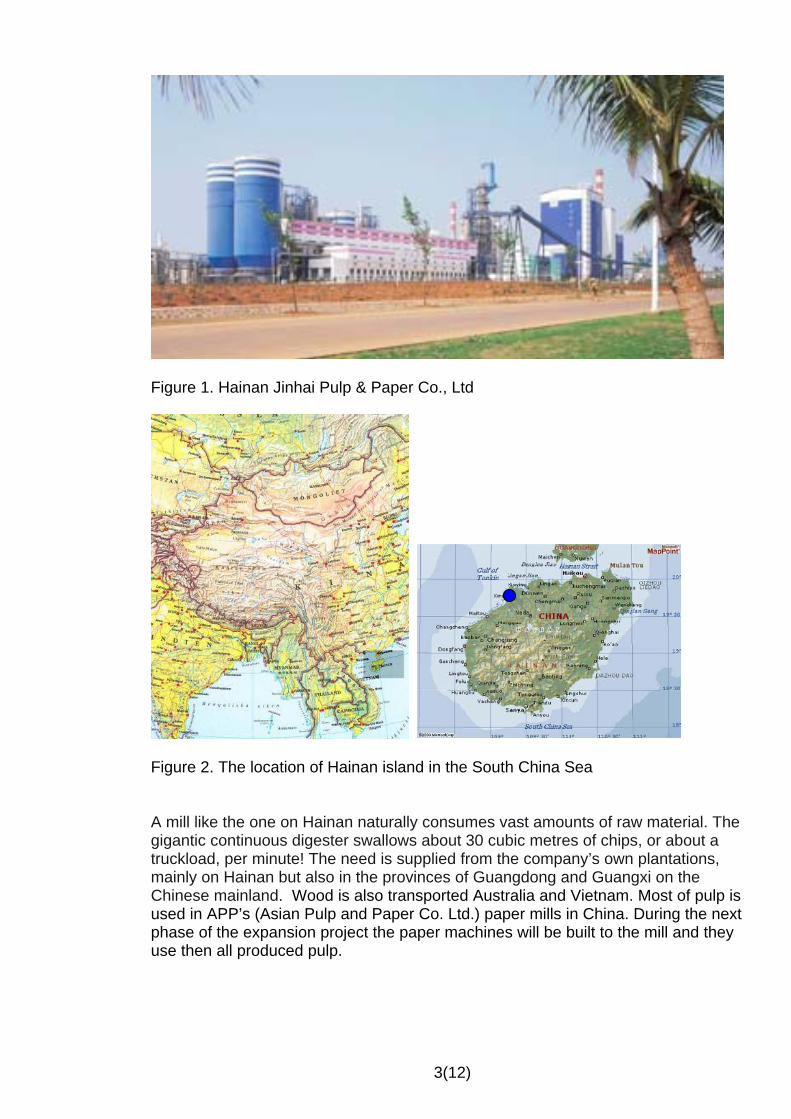
Figure 2. The location of Hainan island in the South China Sea A mill like the one on Hainan naturally consumes vast amounts of raw material. The gigantic continuous digester swallows about 30 cubic metres of chips, or about a truckload, per minute! The need is supplied from the company’s own plantations, mainly on Hainan but also in the provinces of Guangdong and Guangxi on the Chinese mainland. Wood is also transported Australia and Vietnam. Most of pulp is used in APP’s (Asian Pulp and Paper Co. Ltd.) paper mills in China. During the next phase of the expansion project the paper machines will be built to the mill and they use then all produced pulp.

4(12)
1.3 Kvaerner’s delivery Kvaerner delivered to the mill the fiberline, the chlorine dioxide plant, two CYMIC-boilers and the RECOX-recovery boiler. Dimensioning capacity of the world’s largest single line fiberline is 3000 ADT/24h of bleached eucalyptus market pulp. Record load 3400 ADT/24h was achieved in August 2005. The fiberline consists of COMPACT COOKING™, screening, two stages DUALOX™ and a four-stage bleach plant with a DUALD™ and pressurized EO stage. The washing in the fiberline after the digester is made on a total of nine COMPACT PRESS™ units.
Figure 3. Fiberline The capacity of ClO2-plant is 70 t ClO2 /24h. Figure 4. World’s Largest Integrated ClO2 Plant
5(12)
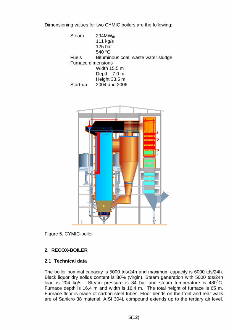
Dimensioning values for two CYMIC boilers are the following:
Steam 294MWth 111 kg/s
125 bar 540 °C
Fuels Bituminous coal, waste water sludge Furnace dimensions
Width 15,5 m Depth 7,0 m Height 33,5 m
Start-up 2004 and 2006
Figure 5. CYMIC-boiler 2. RECOX-BOILER 2.1 Technical data The boiler nominal capacity is 5000 tds/24h and maximum capacity is 6000 tds/24h. Black liquor dry solids content is 80% (virgin). Steam generation with 5000 tds/24h load is 204 kg/s. Steam pressure is 84 bar and steam temperature is 480oC. Furnace depth is 16,4 m and width is 16,4 m. The total height of furnace is 65 m. Furnace floor is made of carbon steel tubes. Floor bends on the front and rear walls are of Sanicro 38 material. AISI 304L compound extends up to the tertiary air level.
6(12)
Superheaters have a wide side spacing of 381 mm and the hottest superheaters have outermost bends made by stainless steel material. 2.2 Scope of supply Kvaerner Power supplied all materials and mechanical parts of the recovery boiler. The scope included also erection supervision, commissioning services and 24 man months “baby-sitting” period. During that period Kvaerner’s commissioning engineer is supporting operators in their daily activities of the boiler operation. Kvaerner’s delivery included also:
• CNCG burning system with CNCG burner at the secondary air level and flare on the top of boiler building
• DNCG burning system with a condensing scrubber. DNCG gases are mixed with high secondary air.
• Dissolving and mixing tank vent gas burning system including condensing scrubber and gas heater.
• Advanced control system, BLRBO, for intelligent sootblowing and constant heat input control.
• CBT (computer based training) with simulator and interactive multimedia training package. (IMT)
• Ash Leaching Plant
Customer delivered the following activities: • Civil works • Erection • Site fabrication of basic plate work and ducts • standard electrical motors • MCC (motor control centres) • Standard pumps • Control valves • DSC • Cables

7(12)
Figure 6. RECOX-boiler Delivery time of RECOX-boiler was 21 months and below is shown some mile stones:
• start of concrete pouring June 2003 • start of steel construction installation September 2003 • start of pressure part installation January 2004 • boiler hydro test July 2004 • boiler chemical cleaning October 2004 • black liquor firing November 2004

8(12)
2.3 The Engineering of RECOX-boiler The size of recovery boilers has become bigger and bigger (figure 7). About 30 years ago the boiler size 1500 tds/24h was considered to be the biggest one which is able to be build; but that was a wrong assumption. Boiler size increased steadily and 2000 tds/24h was achieved in the middle of 80’s, 2500 tds/24h load was exceeded in 1991. One so called XL size boiler (bigger than 2500 tds/24h) started up in 1996 in Far-East and during that time it was seen that black liquor load 4000 tds/24h will be exceeded soon. In 2004 started up Hainan 5000 tds/24h recovery boiler and with that boiler 6000 tds/24h load was exceeded at the end of 2005.
Figure 7. Capacity increase of recovery boilers In Kvaerner Power a special development project was started up in the beginning of 2000. The purpose of that project was to study possibilities to build a real big recovery boiler; XXL size. The most important analyzed areas were those which affected to boiler availability, furnace processes and mechanical designs. The project was carried out in two years and as a result there was ready made concept for the coming huge boilers. Results of this project were then needed already at the end of 2002 when the engineering of Jinhai Pulp & Paper recovery boiler started. Additionally during the design phase certain areas were analyzed more deeply in order to identify possible risk areas and find solutions to them. When world’s biggest boiler was under engineering phase many sophisticated programs were used. RBD-program (Recovery Boiler Designer) was utilized for dimensioning the heating surfaces of boiler and other process related parameters. Fouling Advisor-program was used for analyzing possible risks of fouling and corrosion in flue gas side. CFD-program was used for modelling of temperature and flue gas velocity profiles inside the huge furnace and flue gas passes. By using CFD
4,500,000 lb ds/d
2600 tds/day
8,400,000 lb ds/d
5000-5500 tds/d 200411,200,000 lb ds/d- 12,200,000 lb ds/d
6000 tds/d 2005

9(12)
it was also “easy” to find optimum location for the air port openings on furnace walls. For piping and lay-out engineering was used PDMS 3-D program which is nowadays a daily used engineering tool for the recovery boiler plant engineering. 2.4 Manufacturing and erection of RECOX All pressure parts were manufactured in Kvaerner’s own workshops in Tampere and Lapua. The weight of pressure part was 4000 t and the total length of tubes/piping was 430 km. Boiler steel structure was bought from China and its weight was 4500 t. Auxiliary equipment of boiler were mainly purchased from our regular suppliers in Europe and USA. Huge size of boiler components caused certain challenges in workshops and also during transportation but all those problems were managed to solve without any delays in delivery time.
Figure 8. Nose Arch assembled in the Tampere workshop Customer used two local contractors for erecting the recovery boiler. One contractor was in charge of the erection of four ESP chambers and the other one carried out the rest of the erection work. Contractors had experiences from the erection work of big boilers, mainly coal fired boilers, and the whole erection went according to the plan. Only setback happened during erection of ESP when internals of one concrete chamber collapsed due to wrong installation of supports. Similar problems were detected also in other chambers and they were repaired without any further damages to chambers. Damaged internals had to be replaced by new ones and therefore all chambers were in full operation in September 2005.
16,4 m

10(12)
Figure 9. RECOX-boiler in June 2004

11(12)
2.5 Operation experiences Most of the operators didn’t have any experiences of recovery boiler operation and therefore training of operators was very important topic in our delivery. However, the managers of operators had earlier been working in the other pulp mills in Indonesia and China. The training courses started about one year before the boiler was started up and the boiler simulator and IMT (Interactive Multimedia Training) proved to be very useful in those sessions.
Figure 10. Operators ready for starting up the world’s biggest recovery boiler in June 2004 Black Liquor firing started in November 2004. During that time Kvaerner had the commissioning team for supporting local operators and there were also six experienced operators from the Perawang mill in Indonesia. Also other departments had start-up people from the Perawang mill. When mill started up the boiler load varied quite a lot during the first year of operation mainly due to challenges of start up of green field pulp mill. Boiler load has now been stabilized to a level 5000-5500 tds/24h load. The highest load was achieved in June 2006 when 6500 tds/24h black liquor load was exceeded. Feed water flow was then 252 kg/s. The dry solids content has been in range of 77-80%. Black liquor load variations have been managed to be controlled by a modern air system where primary air ports are located on all walls, secondary and high secondary air ports are only on front and rear walls as well as the tertiary air ports. Secondary air system

12(12)
has so called semi-interlaced air port pattern meaning that small and big ports are opposing each others. Flue gas emissions have been as expected. SO2 and TRS emissions are typically zero. NOx emission has been quite high but main reason for that is high nitrogen content 0.18% in black liquor. Figure 11 shows measured emissions at the end of 2005.
NOx, SO2 and TRS contents in stack
0
50
100
150
200
250
300
350
31.8
.200
5 0:
00
10.9
.200
5 0:
00
20.9
.200
5 0:
00
30.9
.200
5 0:
00
10.1
0.20
05 0
:00
20.1
0.20
05 0
:00
30.1
0.20
05 0
:00
9.11
.200
5 0:
00
19.1
1.20
05 0
:00
29.1
1.20
05 0
:00
9.12
.200
5 0:
00
Time
mg/
Nm
3
Measured NOx in 3 % O2 level Measured SO2
Measured TRS
Figure 11. Measured emissions 2.6 Summary The new pulp mill of Hainan Jinhai Pulp & Paper Co has produced pulp now about 20 months. Dimensioning capacity of fiberline was achieved in the spring 2005 and recovery boiler has managed to handle all black liquor load variations which it has “encountered”. Boiler is running nowadays continuously 5000-5500 tds/24h load. Boiler pressure part has operated as planned. Furnace process with modern air system is working excellently. Boiler has had short outages mainly due to fine tunings in other parts of pulp mill. First official inspection was carried out in the beginning of June 2006 meaning that the boiler was operated 18 months without any inspection inside the furnace. No abnormalities were detected during this inspection showing that from the mechanical point of view the boiler had lasted very well its first operation period.