
the ETR Series Design
106
ETR Series Electric Cylinders with Roller Screw Technology za09 Catalog 1898/US zla10
Transcript of the ETR Series Design

ETR SeriesElectric Cylinders withRoller Screw Technology za09
Catalog 1898/US
Parker Hannifin CorporationActuator Division135 Quadral DriveWadsworth, OH 44281Phone: 330-336-3511www.parker.com/actuatore-mail: [email protected]
Catalog 1898/US10M 08/04 VHG
A Full Spectrum ofProducts to SolveYour Application Needs
ElectromechanicalActuator ProductsActuator DivisionPhone: 330/336-3511Fax: 330/334-3335Web site: www.parker.com/actuatore-mail: [email protected]
ElectromechanicalPositioning SystemsElectromechanical Division North AmericaPhone: 724/861-8200 or 1/800/245-6903Fax: 724/861-3330Web site: www.daedalpositioning.come-mail: [email protected]
Servo and StepperMotion Control SystemsElectromechanical Division North AmericaPhone: 707/584-7558 or 1/800/358-9070Fax: 707/584-2446Applications: 1/800/358-9070Web site: www.compumotor.come-mail: [email protected] [email protected]
Human-Machine Interfaceand Integrated Machine ControlElectromechanical Division North AmericaPhone: 513/831-2340 or 1/800/233-3329Fax: 513/831-5042Web site: www.ctcusa.come-mail: [email protected]
International Electromechanical DivisionsParker Hannifin plcElectromechanical Division EuropeEnglandTel: +44 (0) 1202 69 9000Fax: +44 (0) 1202 69 5750e-mail: [email protected] [email protected] site: www.parker-emd.com
Parker Hannifin GmbHElectromechanical Division EuropeGermanyTel: +49 (0) 781 509 0Fax: +49 (0) 781 509 176e-mail: [email protected] site: www.parker-emd.com
Parker Hannifin SpAElectromechanical Division EuropeItalyTel: +39 02 6601 2478Fax: +39 02 6601 2808e-mail: [email protected] site: www.parker-emd.com
Parker Hannifin Hong Kong Ltd.Tel: 852 2428 8008Fax: 852 2480 4256e-mail: [email protected]
Parker Hannifin Singapore Pte. Ltd.Tel: 65 261 5233Fax: 65 265 5125e-mail: [email protected]
Parker Korea, Ltd.Tel: 82 31 379 2200Fax: 82 31 377 9710
Parker Hannifin Taiwan Co. Ltd.Tel: 886 2 8787 3780Fax: 886 2 8787 3782
zla10

ETR Series
Parker’s Newest Electric Thrust CylinderThe ETR Series Roller Screw CylinderParker’s Actuator Division ispleased to introduce a new familyof electric thrust cylindersfeaturing roller screw drivetechnology - the ETR Series.Designed to provide an efficienttransition from fluid power toelectromechanical drivetechnology, the ETR Series offersa robust, high thrust design withlong life and low maintenancerequirements.
As the worldwide leader in fluidpower cylinder products, Parkercan also combine the benefits ofelectromechanical control with thefamiliar, versatile form factor of
the thrust cylinder. For more than10 years, the ET Series ElectricCylinder, featuring ball screw andacme lead screw drive technology,has set the standard for quality androbust design for electric cylinders.The ETR Series builds on thissuccess by adding the high thrustand long life of the planetaryroller screw.
Roller Screw TechnologyPlanetary roller screws offerdistinct benefits over traditional ballscrew and lead screw mechanisms,as well as benefits over hydraulicand pneumatic linear motion. Thebenefits include increased loadcapacity in comparable packagesizes and long life that iscomparably maintenance-free.
The key to planetary roller screwdesign is the use of rollers, ratherthan ball bearings, as the primaryrolling elements. The rollers providemultiple contact surfaces betweenthe screw shaft and the threadednut. Both the screw and nut employa threaded profile with straightflanks, and both use multi-startthreads. The rollers have a single-start thread, where the thread ismodified to produce rolling contactsimilar to a ball plane.
The lead angles of the nut and rollerare identical to prevent axialmigration of the rollers. The rollershave a gear and cylindrical journal ateach end. The roller gear mesheswith the ring gear of the nut. Thismesh keeps the roller parallel to thescrew shaft and prevents skewing.The ring gears are fixed to the nutby pins.
Roller Screw AdvantagesThrust Capacity and Life: Aplanetary roller screw convertsrotary motion into linear motion, justas a ball screw or lead screw does.Roller screws, with the increasedbearing contactprovided by the rollers, can producemuch higher thrusts and endurethose thrust loads over a muchlonger lifespan.
Simplicity and Flexibility: Inapplications where high loads and/orrapid cycling are required, roller
screw actuators represent anattractive alternative to hydraulic orpneumatic cylinders. Servo-drivenroller screw actuators featuresimplified controls, with no need forcomplex hydraulic or pneumaticcontrol systems with valves, pumps,filters and sensors.Electromechanical control systemsoffer infinite programmability, andcan adapt easily to changingapplication conditions.
Low Maintenance: Roller screwactuator systems requireconsiderably less space than theirfluid power alternatives, whiledelivering long service lives withlittle or no maintenance.
Environmental Considerations:With electromechanical actuatortechnology, leaks are no longer afactor, and the noise producedis minimal.
With an unmatched offering ofpneumatic, hydraulic and electriccylinder products, Parker providesmultiple technology solutions tomore than 100 industrial marketsworldwide.
1) Nut2) Planetary rollers3) Calibrated spacer4) Screw shaft5) Pin6) Ring gear7) Spacer ring8) Spring rings
1
2
6
4
5
78
3
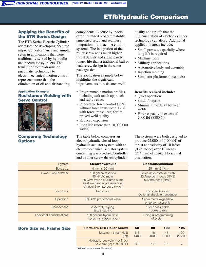
Comparing TechnologyOptions
System Electrohydraulic ElectromechanicalBore size 4 inch (100 mm) 125 mm (5 inch)
Power unit/controller 100 gallon reservoir Servo drive/controller with40 HP AC motor 30 Amp continuous (RMS)
30 GPM variable volume pump 60 Amp peak (RMS)heat exchanger pressure filteroil level & temperature switch
Feedback Transducer Encoder-ResolverOptional absolute transducer
Operation 30 GPM proportional valve Servo motor w/gearboxor servo motor only
Connections Assembly, piping, 1 feedback cabletest & cabling 1 power cable
Additional considerations 100 gallons hydraulic oil Tuning & programminghoses installation labor of system
Bore Size vs. Frame Size Frame size ETR Roller Screw 50 80 100 125Maximum thrust* (kN) 6.5 18 45 100
(lbf) 1400 4000 10,000 22,500
Hydraulic equivalent cylinderbore size (in) at 3000 PSI 0.8 1.3 2.1 4
*With oil lubrication (roller screw)
The table below compares anelectrohydraulic closed loophydraulic actuator system with anelectromechanical actuator systemcontaining a servo-drive/controllerand a roller screw-driven cylinder.
The systems were both designed toproduce 22,000 lbf (100 kN) ofthrust at a velocity of 10 in/sec(0.25 m/sec) over 10 inches(254 mm) of stroke. Horizontalorientation.
Applying the Benefits ofthe ETR Series DesignThe ETR Series Electric Cylinderaddresses the developing need forimproved performance and simplersetup in applications that weretraditionally served by hydraulicand pneumatic cylinders. Thetransition from hydraulic orpneumatic technology toelectromechanical motion controlrepresents more than theelimination of oil and air handling
components. Electric cylindersoffer unlimited programmability,simplified setup and seamlessintegration into machine controlsystems. The integration of theroller screw adds much higherthrust density and significantlylonger life than a traditional ball orlead screw design in the samepackage size.
The application example belowhighlights the significantimprovements to resistance weld
quality and tip life that theimplementation of electric cylindertechnology can afford. Additionalapplication areas include:
• Small presses, especially wherelong life is required
• Machine tools• Military applications• Automotive body and assembly• Injection molding• Simulator platforms (hexapods)
ETR/Hydraulic Comparison
• Programmable motion profiles,including soft touch approachand rapid retract
• Repeatable force control (±5%without force transducer, ±½%with force transducer) for im-proved weld quality
• Reduced expulsion• Long life (more than 10,000,000
welds)
Application Example:
Resistance Welding withServo Control
Benefits realized include:• Quiet operation• Small footprint• Minimal time delay between
welds• Force capacity in excess of
2000 lbf (8800 N)
II
ETR Series Overview
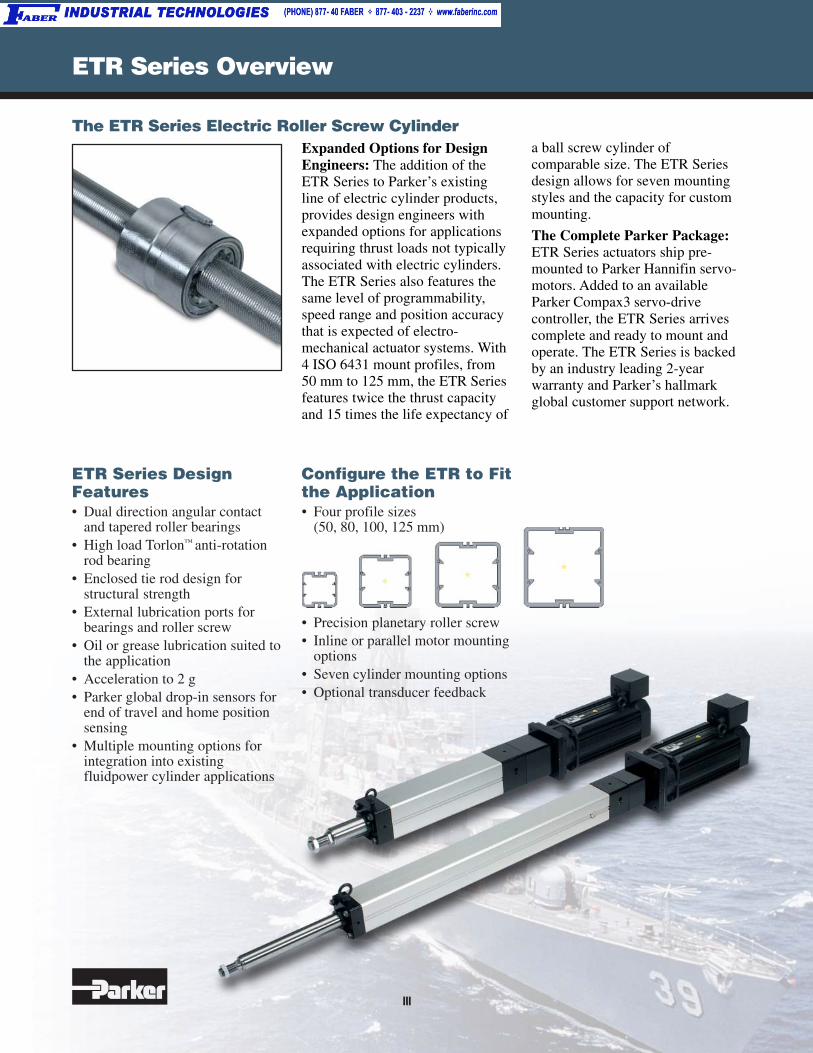
The ETR Series Electric Roller Screw CylinderExpanded Options for DesignEngineers: The addition of theETR Series to Parker’s existingline of electric cylinder products,provides design engineers withexpanded options for applicationsrequiring thrust loads not typicallyassociated with electric cylinders.The ETR Series also features thesame level of programmability,speed range and position accuracythat is expected of electro-mechanical actuator systems. With4 ISO 6431 mount profiles, from50 mm to 125 mm, the ETR Seriesfeatures twice the thrust capacityand 15 times the life expectancy of
a ball screw cylinder ofcomparable size. The ETR Seriesdesign allows for seven mountingstyles and the capacity for custommounting.
The Complete Parker Package:ETR Series actuators ship pre-mounted to Parker Hannifin servo-motors. Added to an availableParker Compax3 servo-drivecontroller, the ETR Series arrivescomplete and ready to mount andoperate. The ETR Series is backedby an industry leading 2-yearwarranty and Parker’s hallmarkglobal customer support network.
ETR Series DesignFeatures• Dual direction angular contact
and tapered roller bearings• High load Torlon™ anti-rotation
rod bearing• Enclosed tie rod design for
structural strength• External lubrication ports for
bearings and roller screw• Oil or grease lubrication suited to
the application• Acceleration to 2 g• Parker global drop-in sensors for
end of travel and home positionsensing
• Multiple mounting options forintegration into existingfluidpower cylinder applications
Configure the ETR to Fitthe Application• Four profile sizes
(50, 80, 100, 125 mm)
• Precision planetary roller screw• Inline or parallel motor mounting
options• Seven cylinder mounting options• Optional transducer feedback
III
ETR Specifications
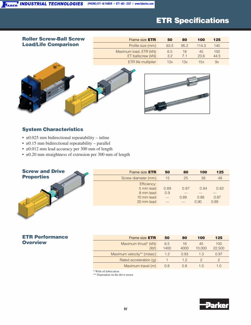
Roller Screw-Ball ScrewLoad/Life Comparison
Frame size ETR 50 80 100 125
Maximum thrust* (kN) 6.5 18 45 100(lbf) 1400 4000 10,000 22,500
Maximum velocity** (m/sec) 1.2 0.93 1.3 0.97
Rated acceleration (g) 1 1.2 2 2
Maximum travel (m) 0.8 0.8 1.0 1.0* With oil lubrication** Dependent on the drive motor
ETR PerformanceOverview
System Characteristics
• ±0.025 mm bidirectional repeatability – inline• ±0.15 mm bidirectional repeatability – parallel• ±0.012 mm lead accuracy per 300 mm of length• ±0.20 mm straightness of extrusion per 300 mm of length
Screw and DriveProperties
Frame size ETR 50 80 100 125
Screw diameter (mm) 15 25 36 48
Efficiency:5 mm lead 0.89 0.87 0.84 0.828 mm lead 0.9 — — —
10 mm lead — 0.89 0.88 0.8720 mm lead — — 0.90 0.89
Frame size ETR 50 80 100 125
Profile size (mm) 63.5 95.2 114.3 140
Maximum load, ETR (kN) 6.5 18 45 100ET ballscrew (kN) 3.2 7.1 23.6 44.5
ETR life multiplier 13x 13x 15x 9x
IV

Complementary Products
The new EMHB Series guidedlinear actuator adds additional loadbearing capacity to the existing ETSeries. Adapted from Parker’ssuccessful pneumatic guidedcylinder technology, the EMHBsolves high normal and moment
Parker Hannifin’s Actuator Divi-sion is your single source forautomated motion in the industrialenvironment. Parker Actuatorfocuses on providing solutions toyour linear motion requirementswith a complete offering of electro-mechanical actuators, pneumaticcylinders and slides, machine
EMHB SeriesGuided Linear Actuator
The ER Series actuator is offeredwith a belt or screw driven internalcarriage design. A sturdy, singlepiece roller bearing carriageprovides load support for long lifein a compact package size.• ISO mounting sizes: 32, 50,
80 mm• Inline and parallel motor mount-
ing options
ER Series ElectricRodless Actuator
• Ideal for dusty environmentswith IP-30 rated strip seal
• Normal load:4480 N with a square rail668 N with roller carriage
• Speeds up to 5 m/sec• Repeatability: ±0.102 mm• Strokes to 6 meters• Clean room compatible
Expanding on the ER, the new ERVSeries was designed with anexternal carriage containingoutboard roller bearing support forhigher loads. The actuator isdesigned to directly interface withParker IPS structural framing,providing a simple and cost effec-tive solution for single or multi-axis systems.
ERV Series ElectricRodless Actuator
• Two sizes: 56, 80 mm• Carriage loads to 4480 N• Extended carriage option• Speeds up to 5 m/sec• Repeatability: ±0.102 mm• Strokes to 6 meters• Internal drive belt
load applications that exceedthe capabilities of a standardelectric cylinder.• Thrust, reach and base styles• Field compatible with
pneumatic cylinders
structure and guarding systems, endeffectors, and multiple standard andcustom system configurations. WithSelectable Levels of Integration™,you choose the level of integrationand Parker will provide the solutionwith components, subsystems andcontrolled motion systems to meetyour specific needs.
V

Complementary Products
Parker pneumatic cylinders areengineered to meet ISO, NFPA andother standards, and they come in avariety of shapes (compact, roundbody and tie rod) and sizes(6-200 mm, ⁵⁄₁₆-14" bores).
PneumaticCylinders
Compax3 The Compax3 family of industrialservo drives and drive/controllersoffers a new level of servo perfor-mance and flexibility. The modularstructure of the Compax3 familyallows options such as intelligentmotion controllers, fieldbus inter-faces and industry standard motorfeedback. Expansion options areavailable to optimize the capabili-ties required for today’s demandingservo applications.• Available in both 120/240 VAC
and 480 VAC input versions• Outputs from 2.5 A (rms) con-
tinuous to 30 A (rms) continuous
• Resolver, encoder or high-resolution SinCos® Absoluterotary encoder feedback (single-or multi-turn)
• Internal regeneration circuitry;external resistor connections foradditional power dissipation
• Easy-to-use wizards-basedconfiguration and programmingvia C3 ServoManager™ software
• Full diagnostic, tuning and4-channel oscilloscope toolsprovided in the standardC3 ServoManager™ software
• CE (EMC and LVD), UL,cUL approval
Whether you need to move a loadfast or slow, in a straight line orthrough an arc, or even sense theload’s position, Parker has acylinder for your application.
Parker IPS Parker Industrial Profile Systems(IPS) provide an extensive range ofextruded aluminum structuralprofiles and mounting accessories.Modular in concept, IPS structuralassemblies are easy to design, buildand modify.
Force Transducer • Fatigue rated• Low height• Guaranteed maximum off-center
load and moment error• Static error band .03-.06%• Low creep
• Low sensitivity to magneticfields
• Temperature compensated• Bayonet connector• Internal and external available
• More than 120 metric profiles• New i Series inch profiles• Advanced fastening techniques• Closed-face profiles available for
special environments• Six North American design and
service centers
VI

Electromechanical Actuator ProductsGuided Cylinder ProductsRotary Actuator ProductsActuator Division135 Quadral DriveWadsworth, OH 44281330-336-3511Fax: 330-334-3335www.parker.com/actuatoremail: [email protected]
Pneumatic CylindersParker Hannifin CorporationActuator Division550 South Wolf RoadDes Plaines, IL 60016847-298-2400Fax: 847-294-2655www.parker.com/actuatoremail: [email protected]
IPS Engineering, fabrication andinventory from service centersacross North America
OhioParker Hannifin CorporationIPS Business Unit135 Quadral DriveWadsworth, OH 44281330-336-3511Fax: 330-334-3335www.parker.com/industrialprofile
CaliforniaParker Hannifin Corporation1636 Pacific StreetUnion City, CA 94587510-487-7505Fax: 510-487-7716
MassachusettsParker Hannifin Corporation19 Technology DriveAuburn, MA 01501508-832-0085Fax: 508-832-4257
MinnesotaParker Hannifin Corporation11170 North 60th StreetStillwater, MN 55082651-351-9330Fax: 651-351-9334
CanadaParker Hannifin Corporation8485 Parkhill DriveMilton, Ontario L9T5E9905-693-3000Fax: 905-876-1958
MexicoParker Hannifin CorporationEje Uno Norte No. 100Parque Ind. Toluca 2000Toluca, Edo. di C.P.50100 Mexico011 52 722 279 9300011 52 722 275 4200Fax: 011 52 722 279 9308

1 Parker Hannifin CorporationActuator DivisionWadsworth, Ohio USA
Electromechanical Actuator ProductsCatalog 1898/US
O
ET
R S
eri
es
Cu
rves
Siz
ing
Dim
.O
rder
ing
Op
tio
ns
Contents
ET
R S
eri
es
Cu
rves
Siz
ing
ETR SeriesElectricCylinders
• Roller Screw• Servo Motor Driven
Dim
.O
rder
ing
Op
tio
ns
Drives, Motorsand Gearheads
Sensors
General Information
Refe
rence
Senso
rsD
rive
s, M
oto
rs, G
ea
rhe
ad
s
• Drives• Controllers• Servo Motors• Precision Gearheads
• Solid State Sensors• Reed Switches
• Densities• Coeffecients of Friction• Conversions• Offer of Sale
Dri
ves
Gea
rhea
ds
Mo
tors

Electromechanical Actuator Products
2 Parker Hannifin CorporationActuator DivisionWadsworth, Ohio USA
Catalog 1898/US
O
Offer of SaleThe items described in this document are hereby offered for sale by Parker Hannifin Corporation, its subsidiaries or its authorizeddistributors. This offer and its acceptance are governed by the provisions stated in the full "Offer of Sale".
WARNINGFAILURE OR IMPROPER SELECTION OR IMPROPER USE OF THE PRODUCTS AND/OR SYSTEMS DESCRIBED HEREINOR RELATED ITEMS CAN CAUSE DEATH, PERSONAL INJURY AND PROPERTY DAMAGE.
This document and other information from Parker Hannifin Corporation, its subsidiaries and authorized distributors provide productand/or system options for further investigation by users having technical expertise. It is important that you analyze all aspects of yourapplication, including consequences of any failure, and review the information concerning the product or system in the currentproduct catalog. Due to the variety of operating conditions and applications for these products or systems, the user, through its ownanalysis and testing, is solely responsible for making the final selection of the products and systems and assuring that all perfor-mance, safety and warning requirements of the application are met.
The products described herein, including without limitation, product features, specifications, designs, availability and pricing, aresubject to change by Parker Hannifin Corporation and its subsidiaries at any time without notice.
© Copyright 2004, Parker Hannifin Corporation. All Rights Reserved.
!

3 Parker Hannifin CorporationActuator DivisionWadsworth, Ohio USA
Electromechanical Actuator ProductsCatalog 1898/US
O
ET
R S
eri
es
Cu
rves
Siz
ing
Dim
.O
rder
ing
Op
tio
ns
Features & Benefits ......................................... 4Specifications .................................................. 5
Performance CurvesHow to Use Curves ................................... 6ETR50 ....................................................... 7ETR80 ....................................................... 8ETR100 ..................................................... 9ETR125 ................................................... 10
DimensionsBasic ....................................................... 11Motor Mounting ....................................... 12
OptionsCylinder Mounting ................................... 14Rod End .................................................. 18
Environmental Considerations ....................... 20Special Modifications ..................................... 21
Sizing and SelectionSelection Guide ....................................... 22Weights ................................................... 36Application Fax Form .............................. 37
Ordering InformationMotor Orientation .................................... 38Customer Supplied Motors ..................... 39ETR50 ..................................................... 40ETR80 ..................................................... 41ETR100 ................................................... 42ETR125 ................................................... 43
ETR Series Electric Cylinders
Electromechanical Actuator Products
4 Parker Hannifin CorporationActuator DivisionWadsworth, Ohio USA
Catalog 1898/US
O
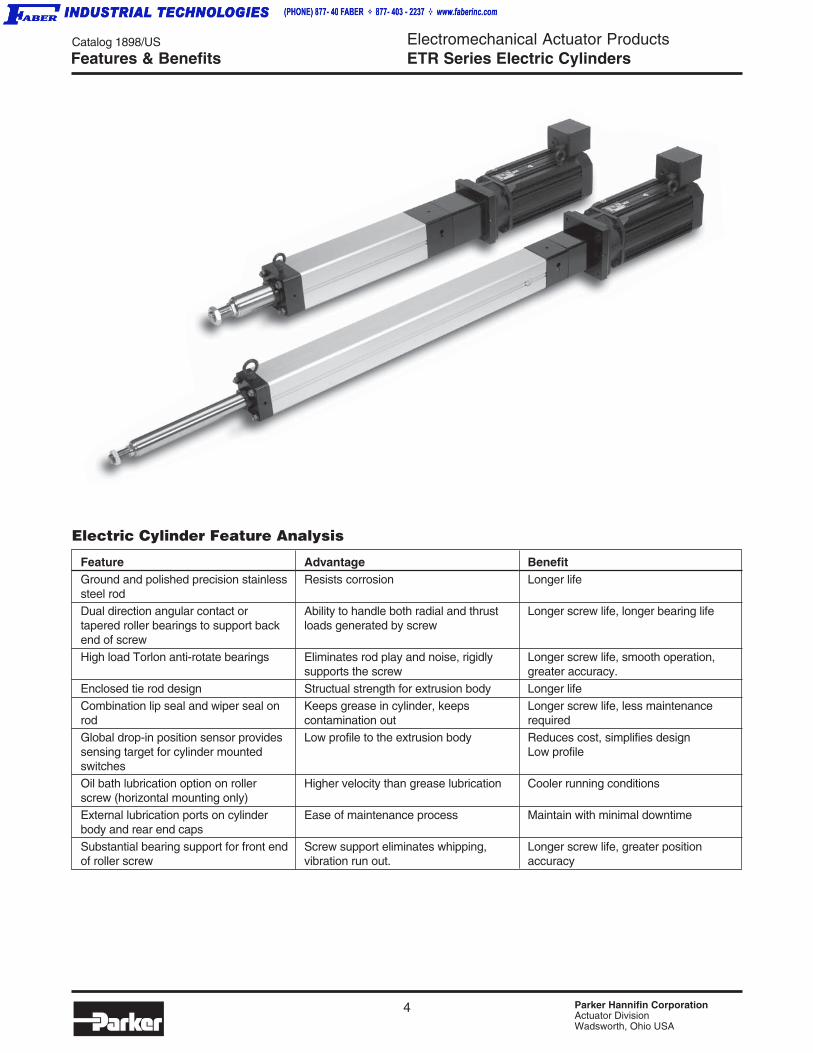
BenefitLonger life
Longer screw life, longer bearing life
Longer screw life, smooth operation,greater accuracy.Longer lifeLonger screw life, less maintenancerequiredReduces cost, simplifies designLow profile
Cooler running conditions
Maintain with minimal downtime
Longer screw life, greater positionaccuracy
AdvantageResists corrosion
Ability to handle both radial and thrustloads generated by screw
Eliminates rod play and noise, rigidlysupports the screwStructual strength for extrusion bodyKeeps grease in cylinder, keepscontamination outLow profile to the extrusion body
Higher velocity than grease lubrication
Ease of maintenance process
Screw support eliminates whipping,vibration run out.
Electric Cylinder Feature Analysis
FeatureGround and polished precision stainlesssteel rodDual direction angular contact ortapered roller bearings to support backend of screwHigh load Torlon anti-rotate bearings
Enclosed tie rod designCombination lip seal and wiper seal onrodGlobal drop-in position sensor providessensing target for cylinder mountedswitchesOil bath lubrication option on rollerscrew (horizontal mounting only)External lubrication ports on cylinderbody and rear end capsSubstantial bearing support for front endof roller screw
Features & Benefits ETR Series Electric Cylinders

5 Parker Hannifin CorporationActuator DivisionWadsworth, Ohio USA
Electromechanical Actuator ProductsCatalog 1898/US
O
ET
R S
eri
es
Cu
rves
Siz
ing
Dim
.O
rder
ing
Op
tio
ns
Performance Overview
System CharacteristicsBidirectional repeatability - Inline, mm (in) ±0.025 (±0.001)
Bidirectional repeatability - Parallel, mm (in) ±0.15 (±0.006)
Lead accuracy per 300mm of length, mm (in) ±0 .012 (±0.0005)
Straightness of extrusion per 300mm of length, mm (in) ±0.20 (±0.008)
Screw and Drive Properties
Size Lead Efficiency Pulley Diameter(mm) (mm)
505 0.89 44.6
8 0.9 44.6
805 0.87 71.3
10 0.89 71.3
5 0.84 86.6
100 10 0.88 86.6
20 0.9 86.6
5 0.82 101.9
125 10 0.87 101.9
20 0.89 101.9
Specifications
ETR50 ETR80 ETR100 ETR125Max Thrust, kN (lb) 6.5 (1460) 18 (4050) 45 (10,120) 100 (22,480)
Max Speed - Oil Cooled, mm/sec (in/sec) 1244 (49) 933 (37) 1296 (51) 972 (38)
Max Speed - Grease Cooled, mm/sec (in/sec) 933 (37) 700 (28) 972 (38) 729 (29)
Max Acceleration* , mm/sec2 (in/sec2) 8,912 (351) 11,140 (439) 22,280 (877) 22,280 (877)
Max Body Inertia, cm4 (in4) 1107 (26.6) 450 (10.8) 187 (4.49) 45 (1.08)
Max Stroke, mm (in) 800 (31.5) 800 (31.5) 1000 (39.4) 1000 (39.4)
*Acceleration is dependent on the drive motor.
Operation Temperature Range
0°C to 60°C (32°F to 140°F)
Profile Extrusions
ETR50 ETR125ETR80 ETR100
ETR Series Electric Cylinders
Electromechanical Actuator ProductsETR Series Electric Cylinders
6 Parker Hannifin CorporationActuator DivisionWadsworth, Ohio USA
Catalog 1898/US
OCurve Interpretation
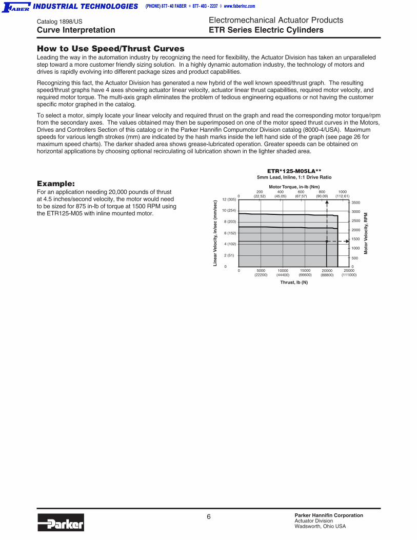
How to Use Speed/Thrust CurvesLeading the way in the automation industry by recognizing the need for flexibility, the Actuator Division has taken an unparalleledstep toward a more customer friendly sizing solution. In a highly dynamic automation industry, the technology of motors anddrives is rapidly evolving into different package sizes and product capabilities.
Recognizing this fact, the Actuator Division has generated a new hybrid of the well known speed/thrust graph. The resultingspeed/thrust graphs have 4 axes showing actuator linear velocity, actuator linear thrust capabilities, required motor velocity, andrequired motor torque. The multi-axis graph eliminates the problem of tedious engineering equations or not having the customerspecific motor graphed in the catalog.
To select a motor, simply locate your linear velocity and required thrust on the graph and read the corresponding motor torque/rpmfrom the secondary axes. The values obtained may then be superimposed on one of the motor speed thrust curves in the Motors,Drives and Controllers Section of this catalog or in the Parker Hannifin Compumotor Division catalog (8000-4/USA). Maximumspeeds for various length strokes (mm) are indicated by the hash marks inside the left hand side of the graph (see page 26 formaximum speed charts). The darker shaded area shows grease-lubricated operation. Greater speeds can be obtained onhorizontal applications by choosing optional recirculating oil lubrication shown in the lighter shaded area.
Example:For an application needing 20,000 pounds of thrustat 4.5 inches/second velocity, the motor would needto be sized for 875 in-lb of torque at 1500 RPM usingthe ETR125-M05 with inline mounted motor.
0
Thrust, lb (N)
Lin
earV
elo
city
, in
/sec
(m
m/s
ec)
ETR*125-M05LA**5mm Lead, Inline, 1:1 Drive Ratio
Mo
torV
elo
city
,RP
M
Motor Torque, in-lb (Nm)
3500
3000
2500
2000
0
200(22.52)
400(45.05)
800(90.09)
5000(22200)
20000(88800)
25000(111000)
15000(66600)
10000(44400)
600(67.57)
1500
1000
500
4 (102)
8 (203)
12 (305)
2 (51)
6 (152)
10 (254)
0
01000
(112.61)

7 Parker Hannifin CorporationActuator DivisionWadsworth, Ohio USA
Electromechanical Actuator ProductsETR Series Electric Cylinders
Catalog 1898/US
O
ET
R S
eri
es
Cu
rves
Siz
ing
Dim
.O
rder
ing
Op
tio
ns
0
Thrust, lb (N)
Lin
earV
elo
city
, in
/sec
(m
m/s
ec)
ETR*50-M05LA**5mm Lead, Inline, 1:1 Drive Ratio
Mo
torV
elo
city
,RP
M
10000
Motor Torque, in-lb (Nm)
8000
6000
4000
2000
00
10 (254)
20 (508)
30 (762)
0
5 (127)
35 (889)
25 (635)
15 (381)
0 200(888)
800(3552)
1000(4440)
1200(5328)
Thrust, lb (N)
Lin
earV
elo
city
, in
/sec
(m
m/s
ec)
ETR*50-M05PA**5mm Lead, Parallel, 1:1 Drive Ratio
Mo
torV
elo
city
,RP
M
Motor Torque, in-lb (Nm)10
(1.13)20
(2.25)30
(3.38)40
(4.50)50
(5.63)60
(6.76)
4000
3000
2000
1000
0600
(2664)400
(1776)
0
4 (102)
8 (203)
12 (305)
16 (406)
0
2 (51)
6 (152)
10 (254)
14 (356)
18 (457)5000
6000
1400(6216)
1600(7104)
20 (508)
10(1.13)
20(2.25)
30(3.38)
40(4.50)
50(5.63)
60(6.76)
200(888)
800(3552)
1000(4440)
1200(5328)
600(2664)
400(1776)
1400(6216)
1600(7104)
0
Thrust, lb (N)
Lin
earV
elo
city
, in
/sec
(m
m/s
ec)
ETR*50-M08LA**8mm Lead, Inline, 1:1 Drive Ratio
Mo
torV
elo
city
,RP
M
10000
Motor Torque, in-lb (Nm)
8000
6000
4000
2000
00
20 (508)
40 (1016)
60 (1524)0
10 (254)
50 (1270)
30 (762)
20(2.25)
40(4.50)
60(6.76)
80(9.01)
200(888)
800(3552)
1000(4440)
1200(5328)
600(2664)
400(1776)
1400(6216)
1600(7104)
70(7.88)
90(10.14)
50(5.63)
30(3.38)
10(1.13)
0 200(888)
800(3552)
1000(4440)
1200(5328)
Thrust, lb (N)
Lin
earV
elo
city
, in
/sec
(m
m/s
ec)
ETR*50-M08PA**8mm Lead, Parallel, 1:1 Drive Ratio
Mo
torV
elo
city
,RP
M
Motor Torque, in-lb (Nm)20
(2.25)40
(4.50)60
(6.76)80
(9.01)100
(11.26)
4000
3000
2000
1000
0600
(2664)400
(1776)
0
0
5000
1400(6216)
1600(7104)
10 (254)
20 (508)
30 (762)
5 (127)
25 (635)
15 (381)
1800(7992)
600mm
750mm
1000mm
750mm
1000mm
1000mm
750mm
450mm (oil)
1000mm
450mm (oil)
600mm
750mm
600mm
600mm
ETR50 Curves
Darker shaded area shows operation with grease lubrication; lighter shaded area shows operation with optional recircu-lating oil lubrication available for horizontal applications only. Maximum speeds for various stroke lengths are shown byhash marks inside the left edge of the chart. See page 26 for maximum speed tables.

Electromechanical Actuator ProductsETR Series Electric Cylinders
8 Parker Hannifin CorporationActuator DivisionWadsworth, Ohio USA
Catalog 1898/US
O
0
Thrust, lb (N)
Lin
earV
elo
city
, in
/sec
(m
m/s
ec)
ETR*80-M05LA**5mm Lead, Inline, 1:1 Drive Ratio
Mo
torV
elo
city
,RP
M
Motor Torque, in-lb (Nm)
6000
4000
2000
0
020
(2.25)40
(4.50)60
(6.76)80
(9.01)100
(11.26)120
(13.51)
0
Thrust, lb (N)
Lin
earV
elo
city
, in
/sec
(m
m/s
ec)
ETR*80-M10LA**10mm Lead, Inline, 1:1 Drive Ratio
Mo
torV
elo
city
,RP
M
5000
Motor Torque, in-lb (Nm)
3000
6000
4000
2000
0
0 500(2220)
2000(8880)
2500(11100)
3000(13320)
Thrust, lb (N)
Lin
earV
elo
city
, in
/sec
(m
m/s
ec)
ETR*80-M10PA**10mm Lead, Parallel, 1:1 Drive Ratio
Mo
torV
elo
city
,RP
M
Motor Torque, in-lb (Nm)50
(5.63)100
(11.26)150
(16.89)200
(22.52)250
(28.15)
4000
3000
2000
1000
01500
(6660)1000
(4440)
0
10 (254)
20 (508)
30 (762)
0
5 (127)
15 (381)
25 (635)
35 (889)5000
3500(15540)
0 2000(8880)
3000(13320)
Thrust, lb (N)
Lin
earV
elo
city
, in
/sec
(m
m/s
ec)
ETR*80-M05PA**5mm Lead, Parallel, 1:1 Drive Ratio
Mo
torV
elo
city
,RP
M
Motor Torque, in-lb (Nm)20
(2.25)40
(4.50)60
(6.76)80
(9.01)100
(11.26)120
(13.51)
4000
3000
2000
1000
01000
(4440)
0
4 (102)
8 (203)
12 (305)
16 (406)
0
2 (51)
6 (152)
10 (254)
14 (356)
18 (457)
5000
4000(17760)
140(15.77)
160(18.02)
180(20.27)
1000
50(5.63)
100(11.26)
150(16.89)
200(22.52)
250(28.15)
300(33.78)
350(39.41)
0
10 (254)
20 (508)
30 (762)
5 (127)
35 (889)
25 (635)
15 (381)
40 (1016)
2000(8880)
3000(13320)
1000(4440)
4000(17760)
02000
(8880)3000
(13320)1000
(4440)4000
(17760)
0
5000
3000
1000
140(15.77)
160(18.02)
180(20.27)
4 (102)
8 (203)
12 (305)
16 (406)
2 (51)
6 (152)
10 (254)
14 (356)
18 (457)
20 (508)
1000mm1000mm
750mm (oil)
750mm (oil)
1000mm1000mm
Oil
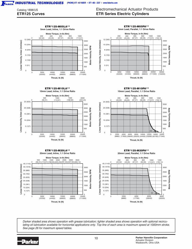
ETR80 Curves
Darker shaded area shows operation with grease lubrication; lighter shaded area shows operation with optional recircu-lating oil lubrication available for horizontal applications only. Maximum speeds for various stroke lengths are shown byhash marks inside the left edge of the chart. See page 26 for maximum speed tables.

9 Parker Hannifin CorporationActuator DivisionWadsworth, Ohio USA
Electromechanical Actuator ProductsETR Series Electric Cylinders
Catalog 1898/US
O
ET
R S
eri
es
Cu
rves
Siz
ing
Dim
.O
rder
ing
Op
tio
ns
0
Thrust, lb (N)
Lin
earV
elo
city
, in
/sec
(m
m/s
ec)
ETR*100-M05LA**5mm Lead, Inline, 1:1 Drive Ratio
Mo
torV
elo
city
,RP
M
4000
Motor Torque, in-lb (Nm)
3500
3000
2500
2000
0
050
(5.63)150
(16.89)450
(50.68)
2000(8880)
8000(35520)
10000(44400)
12000(53280)
6000(26640)
4000(17760)
250(28.15)
1500
1000
500
4 (102)
8 (203)
12 (305)
2 (51)
6 (152)
10 (254)
14 (356)
00 2000
(8880)8000
(35520)10000
(44400)12000
(53280)
Thrust, lb (N)
Lin
earV
elo
city
, in
/sec
(m
m/s
ec)
ETR*100-M05PA**5mm Lead, Parallel, 1:1 Drive Ratio
Mo
torV
elo
city
,RP
M
Motor Torque, in-lb (Nm)100
(11.26)200
(22.52)300
(33.78)400
(45.05)500
(56.31)
3500
3000
2000
1000
6000(26640)
4000(17760)
0
4 (102)
8 (203)
12 (305)
0
2 (51)
6 (152)
10 (254)
14 (356)4000
14000(62160)
1500
2500
500
0
0
Thrust, lb (N)
Lin
earV
elo
city
, in
/sec
(m
m/s
ec)
ETR*100-M10LA**10mm Lead, Inline, 1:1 Drive Ratio
Mo
torV
elo
city
,RP
M
4000
Motor Torque, in-lb (Nm)
3500
3000
2500
2000
0
0100
(11.26)300
(33.78)700
(78.83)
2000(8880)
8000(35520)
10000(44400)
12000(53280)
6000(26640)
4000(17760)
500(56.31)
1500
1000
500
10 (254)
20 (508)
30 (762)
5 (127)
15 (381)
25 (635)
0
4500
0 1000(4440)
4000(17760)
5000(22200)
6000(26640)
Thrust, lb (N)
Lin
earV
elo
city
, in
/sec
(m
m/s
ec)
ETR*100-M10PA**10mm Lead, Parallel, 1:1 Drive Ratio
Mo
torV
elo
city
,RP
M
Motor Torque, in-lb (Nm)100
(11.26)200
(22.52)300
(33.78)400
(45.05)500
(56.31)
3500
3000
2000
1000
3000(13320)
2000(8880)
0
10 (254)
20 (508)
30 (762)0
5 (127)
15 (381)
25 (635)4000
7000(31080)
1500
2500
500
08000
(35520)
4500
600(67.57)
0
Thrust, lb (N)
Lin
earV
elo
city
, in
/sec
(m
m/s
ec)
ETR*100-M20LA**20mm Lead, Inline, 1:1 Drive Ratio
Mo
torV
elo
city
,RP
M
4000
Motor Torque, in-lb (Nm)
3500
3000
2500
2000
0
1800(202.70)
2000(8880)
8000(35520)
10000(44400)
12000(53280)
6000(26640)
4000(17760)
1500
1000
500
20 (508)
40 (1016)
60 (1524)
10 (254)
30 (762)
50 (1270)
0
45000
0 500(2220)
2000(8880)
2500(11100)
3000(13320)
Thrust, lb (N)
Lin
earV
elo
city
, in
/sec
(m
m/s
ec)
ETR*100-M20PA**20mm Lead, Parallel, 1:1 Drive Ratio
Mo
torV
elo
city
,RP
M
Motor Torque, in-lb (Nm)100
(11.26)200
(22.52)300
(33.78)400
(45.05)500
(56.31)
3500
3000
2000
1000
1500(6660)
1000(4440)
0
0
4000
3500(15540)
1500
2500
500
04000
(17760)
4500
600(67.57)
20 (508)
40 (1016)
60 (1524)
10 (254)
30 (762)
50 (1270)
600(67.57)
1000(112.61)
200(22.52)
1400(157.66)
900(101.35)
350(39.41)
Oil
Oil
ETR100 Curves
Darker shaded area shows operation with grease lubrication; lighter shaded area shows operation with optional recircu-lating oil lubrication available for horizontal applications only. Top line of each area is maximum speed at 1000mm stroke.See page 26 for maximum speed tables.
Electromechanical Actuator ProductsETR Series Electric Cylinders
10 Parker Hannifin CorporationActuator DivisionWadsworth, Ohio USA
Catalog 1898/US
O
0
Thrust, lb (N)
Lin
earV
elo
city
, in
/sec
(m
m/s
ec)
ETR*125-M05LA**5mm Lead, Inline, 1:1 Drive Ratio
Mo
torV
elo
city
,RP
M
Motor Torque, in-lb (Nm)
3500
3000
2500
2000
0
200(22.52)
400(45.05)
800(90.09)
5000(22200)
20000(88800)
25000(111000)
15000(66600)
10000(44400)
600(67.57)
1500
1000
500
4 (102)
8 (203)
12 (305)
2 (51)
6 (152)
10 (254)
0
01000
(112.61)
0 5000(22200)
20000(88800)
25000(111000)
30000(133200)
Thrust, lb (N)
Lin
earV
elo
city
, in
/sec
(m
m/s
ec)
ETR*125-M05PA**5mm Lead, Parallel, 1:1 Drive Ratio
Mo
torV
elo
city
,RP
M
Motor Torque, in-lb (Nm)1200
(135.14)200
(22.52)800
(90.09)400
(45.05)1000
(112.61)
3500
3000
2000
1000
15000(66600)
10000(44400)
0
1500
2500
500
600(67.57)
0
4 (102)
8 (203)
12 (305)
2 (51)
6 (152)
10 (254)
0 2000(8880)
8000(35520)
10000(44400)
12000(53280)
Thrust, lb (N)
Lin
earV
elo
city
, in
/sec
(m
m/s
ec)
Mo
torV
elo
city
, RP
M
3500
3000
2000
1000
6000(26640)
4000(17600)
0
1500
2500
500
ETR*125-M10PA**10mm Lead, Parallel, 1:1 Drive Ratio
Motor Torque, in-lb (Nm)1200
(135.14)200
(22.52)800
(90.09)400
(45.05)1000
(112.61)600
(67.57)
0
10 (254)
20 (508)
5 (127)
15 (381)
25 (635)
14000(62160)
16000(71040)
0
Thrust, lb (N)
Lin
earV
elo
city
, in
/sec
(m
m/s
ec)
ETR*125-M10LA**10mm Lead, Inline, 1:1 Drive Ratio
Mo
torV
elo
city
,RP
M
Motor Torque, in-lb (Nm)
3500
3000
2500
2000
0
500(56.31)
1000(112.61)
1500(168.92)
5000(22200)
20000(88800)
25000(111000)
15000(66600)
10000(44400)
1500
1000
500
0
02000
(225.23)
10 (254)
20 (508)
5 (127)
15 (381)
25 (635)
0
Thrust, lb (N)
Lin
earV
elo
city
, in
/sec
(m
m/s
ec)
ETR*125-M20LA**20mm Lead, Inline, 1:1 Drive Ratio
Mo
torV
elo
city
,RP
M
Motor Torque, in-lb (Nm)
3000
2500
2000
0
500(56.31)
1000(112.61)
1500(168.92)
5000(22200)
20000(88800)
25000(111000)
15000(66600)
10000(44400)
1500
1000
500
0
02000
(225.23)
10 (254)
20 (508)
5 (127)
15 (381)
25 (635)
2500(281.53)
3000(337.84)
3500(394.14)
30 (762)
35 (889)
40 (1016)
45 (1143)
0 4000(17760)
6000(26640)
Thrust, lb (N)
Lin
earV
elo
city
, in
/sec
(m
m/s
ec)
Mo
torV
elo
city
, RP
M3000
2000
1000
2000(8880)
0
1500
2500
500
ETR*125-M20PA**20mm Lead, Parallel, 1:1 Drive Ratio
Motor Torque, in-lb (Nm)1200
(135.14)200
(22.52)800
(90.09)400
(45.05)1000
(112.61)600
(67.57)
08000
(35520)
10 (254)
20 (508)
5 (127)
15 (381)
25 (635)
30 (762)
35 (889)
40 (1016)
45 (1143)
0
0
0
Oil
Oil
ETR125 Curves
Darker shaded area shows operation with grease lubrication; lighter shaded area shows operation with optional recircu-lating oil lubrication available for horizontal applications only. Top line of each area is maximum speed at 1000mm stroke.See page 26 for maximum speed tables.
Catalog 1898/US
Basic DimensionsElectromechanical Actuator ProductsETR Series Electric Cylinders
11 Parker Hannifin CorporationActuator DivisionWadsworth, Ohio USA
ET
R S
eri
es
Cu
rves
Siz
ing
Dim
.O
rder
ing
Op
tio
ns
Dimensions
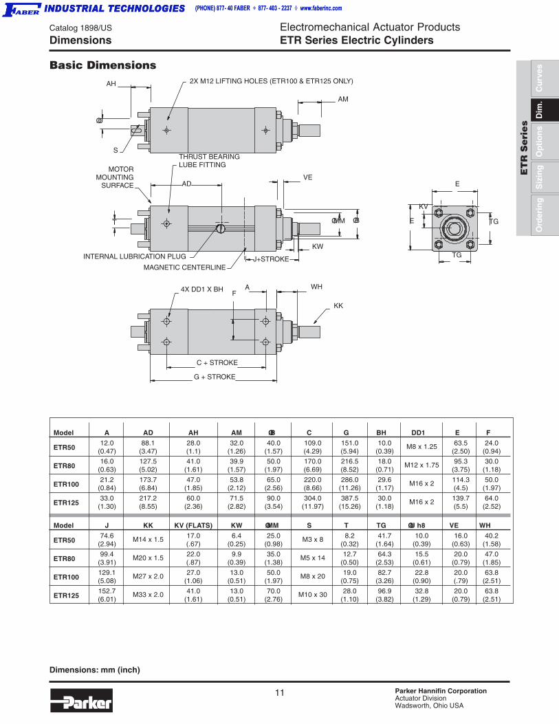
Basic Dimensions
Dimensions: mm (inch)
Model A AD AH AM ØB C G BH DD1 E F
ETR5012.0 88.1 28.0 32.0 40.0 109.0 151.0 10.0 M8 x 1.25 63.5 24.0
(0.47) (3.47) (1.1) (1.26) (1.57) (4.29) (5.94) (0.39) (2.50) (0.94)
ETR8016.0 127.5 41.0 39.9 50.0 170.0 216.5 18.0 M12 x 1.75 95.3 30.0
(0.63) (5.02) (1.61) (1.57) (1.97) (6.69) (8.52) (0.71) (3.75) (1.18)
ETR10021.2 173.7 47.0 53.8 65.0 220.0 286.0 29.6 M16 x 2 114.3 50.0
(0.84) (6.84) (1.85) (2.12) (2.56) (8.66) (11.26) (1.17) (4.5) (1.97)
ETR12533.0 217.2 60.0 71.5 90.0 304.0 387.5 30.0 M16 x 2 139.7 64.0
(1.30) (8.55) (2.36) (2.82) (3.54) (11.97) (15.26) (1.18) (5.5) (2.52)
Model J KK KV (FLATS) KW ØMM S T TG ØU h8 VE WH
ETR5074.6 M14 x 1.5 17.0 6.4 25.0 M3 x 8 8.2 41.7 10.0 16.0 40.2
(2.94) (.67) (0.25) (0.98) (0.32) (1.64) (0.39) (0.63) (1.58)
ETR8099.4 M20 x 1.5 22.0 9.9 35.0 M5 x 14 12.7 64.3 15.5 20.0 47.0
(3.91) (.87) (0.39) (1.38) (0.50) (2.53) (0.61) (0.79) (1.85)
ETR100129.1 M27 x 2.0 27.0 13.0 50.0 M8 x 20 19.0 82.7 22.8 20.0 63.8(5.08) (1.06) (0.51) (1.97) (0.75) (3.26) (0.90) (.79) (2.51)
ETR125152.7 M33 x 2.0 41.0 13.0 70.0 M10 x 30 28.0 96.9 32.8 20.0 63.8(6.01) (1.61) (0.51) (2.76) (1.10) (3.82) (1.29) (0.79) (2.51)
2X M12 LIFTING HOLES (ETR100 & ETR125 ONLY)
AM
THRUST BEARINGLUBE FITTING
VE
AH
ØU
S
AD
MOTORMOUNTING
SURFACE
T
INTERNAL LUBRICATION PLUG
MAGNETIC CENTERLINE
KW
ØMM ØB
WH
KK
G + STROKE
C + STROKE
4X DD1 X BH
J+STROKE
KV
E
E
TG
TG
FA
12 Parker Hannifin CorporationActuator DivisionWadsworth, Ohio USA
Electromechanical Actuator ProductsETR Series Electric Cylinders
Catalog 1898/US
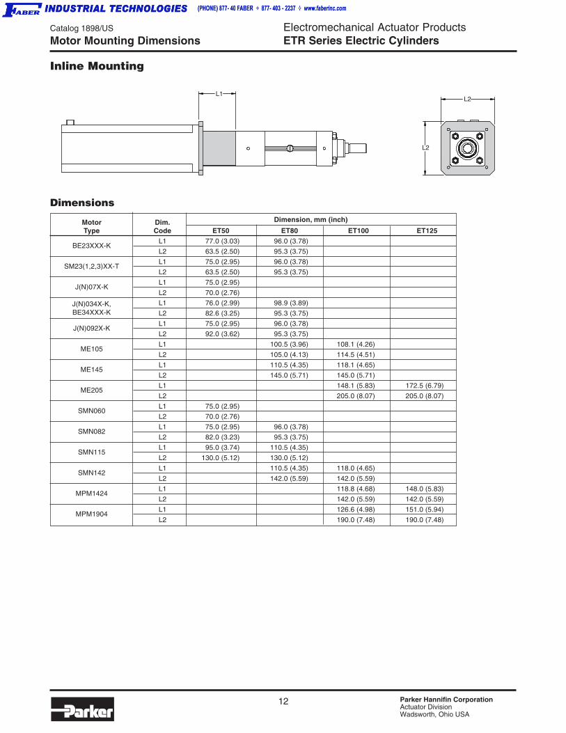
ETB SeriesMotor Mounting Dimensions
Inline Mounting
Motor Dim. Dimension, mm (inch)
Type Code ET50 ET80 ET100 ET125
BE23XXX-KL1 77.0 (3.03) 96.0 (3.78)
L2 63.5 (2.50) 95.3 (3.75)
SM23(1,2,3)XX-TL1 75.0 (2.95) 96.0 (3.78)
L2 63.5 (2.50) 95.3 (3.75)
J(N)07X-KL1 75.0 (2.95)
L2 70.0 (2.76)
J(N)034X-K, L1 76.0 (2.99) 98.9 (3.89)BE34XXX-K L2 82.6 (3.25) 95.3 (3.75)
J(N)092X-KL1 75.0 (2.95) 96.0 (3.78)
L2 92.0 (3.62) 95.3 (3.75)
ME105L1 100.5 (3.96) 108.1 (4.26)
L2 105.0 (4.13) 114.5 (4.51)
ME145L1 110.5 (4.35) 118.1 (4.65)
L2 145.0 (5.71) 145.0 (5.71)
ME205L1 148.1 (5.83) 172.5 (6.79)
L2 205.0 (8.07) 205.0 (8.07)
SMN060L1 75.0 (2.95)
L2 70.0 (2.76)
SMN082L1 75.0 (2.95) 96.0 (3.78)
L2 82.0 (3.23) 95.3 (3.75)
SMN115L1 95.0 (3.74) 110.5 (4.35)
L2 130.0 (5.12) 130.0 (5.12)
SMN142L1 110.5 (4.35) 118.0 (4.65)
L2 142.0 (5.59) 142.0 (5.59)
MPM1424L1 118.8 (4.68) 148.0 (5.83)
L2 142.0 (5.59) 142.0 (5.59)
MPM1904L1 126.6 (4.98) 151.0 (5.94)
L2 190.0 (7.48) 190.0 (7.48)
Dimensions
L1
L2
L2
Catalog 1898/US
Basic DimensionsElectromechanical Actuator ProductsETR Series Electric Cylinders
13 Parker Hannifin CorporationActuator DivisionWadsworth, Ohio USA
ET
R S
eri
es
Cu
rves
Siz
ing
Dim
.O
rder
ing
Op
tio
ns
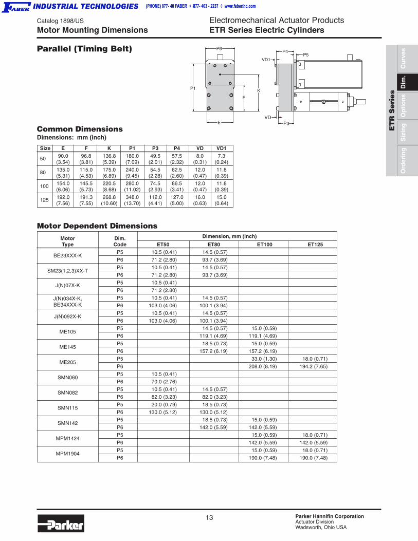
Parallel (Timing Belt)
Size E F K P1 P3 P4 VD VD1
50 90.0 96.8 136.8 180.0 49.5 57.5 8.0 7.3(3.54) (3.81) (5.39) (7.09) (2.01) (2.32) (0.31) (0.24)
80 135.0 115.0 175.0 240.0 54.5 62.5 12.0 11.8(5.31) (4.53) (6.89) (9.45) (2.28) (2.60) (0.47) (0.39)
100 154.0 145.5 220.5 280.0 74.5 86.5 12.0 11.8(6.06) (5.73) (8.68) (11.02) (2.93) (3.41) (0.47) (0.39)
125 192.0 191.3 268.8 348.0 112.0 127.0 16.0 15.0(7.56) (7.55) (10.60) (13.70) (4.41) (5.00) (0.63) (0.64)
Motor Mounting Dimensions
Common DimensionsDimensions: mm (inch)
Motor Dependent Dimensions
E
K
F
P4P5
VD1
VDP3
P6
P1
Motor Dim. Dimension, mm (inch)
Type Code ET50 ET80 ET100 ET125
BE23XXX-KP5 10.5 (0.41) 14.5 (0.57)
P6 71.2 (2.80) 93.7 (3.69)
SM23(1,2,3)XX-TP5 10.5 (0.41) 14.5 (0.57)
P6 71.2 (2.80) 93.7 (3.69)
J(N)07X-K P5 10.5 (0.41)
P6 71.2 (2.80)
J(N)034X-K, P5 10.5 (0.41) 14.5 (0.57)BE34XXX-K P6 103.0 (4.06) 100.1 (3.94)
J(N)092X-KP5 10.5 (0.41) 14.5 (0.57)
P6 103.0 (4.06) 100.1 (3.94)
ME105P5 14.5 (0.57) 15.0 (0.59)
P6 119.1 (4.69) 119.1 (4.69)
ME145P5 18.5 (0.73) 15.0 (0.59)
P6 157.2 (6.19) 157.2 (6.19)
ME205P5 33.0 (1.30) 18.0 (0.71)
P6 208.0 (8.19) 194.2 (7.65)
SMN060P5 10.5 (0.41)
P6 70.0 (2.76)
SMN082P5 10.5 (0.41) 14.5 (0.57)
P6 82.0 (3.23) 82.0 (3.23)
SMN115P5 20.0 (0.79) 18.5 (0.73)
P6 130.0 (5.12) 130.0 (5.12)
SMN142P5 18.5 (0.73) 15.0 (0.59)
P6 142.0 (5.59) 142.0 (5.59)
MPM1424P5 15.0 (0.59) 18.0 (0.71)
P6 142.0 (5.59) 142.0 (5.59)
MPM1904P5 15.0 (0.59) 18.0 (0.71)
P6 190.0 (7.48) 190.0 (7.48)

14 Parker Hannifin CorporationActuator DivisionWadsworth, Ohio USA
Electromechanical Actuator ProductsETR Series Electric Cylinders
Catalog 1898/US
ETB Series
Trunnion Mounting (MT1, MT2)Cylinder Mounting Code D1, D2
Inline Motor Mounting
DIMENSIONS: mmInch equivalents for millimeter dimensions are shown in ( ).
Cylinder Mounting Options
ØTD TL
TC TC1
H
F N
TLØTD
TL1
ØTD1
X1 + STROKE
Size F H N X1 TC TC1 TD TD1 TL TL1
5012.0 52.2 25.0 166.2 95.5 127.3 20.0 40.0 16.0 15.9
(0.47) (2.06) (0.98) (6.54) (3.76) (5.01) (0.79) (1.57) (0.63) (0.63)
8016.0 63.0 32.0 230.0 145.3 185.3 32.0 50.0 25.0 20.0
(0.63) (2.48) (1.26) (9.06) (5.72) (7.30) (1.26) (1.97) (0.98) (0.79)
10021.3 85.0 48.8 301.0 178.3 218.3 40.0 60.0 32.0 20.0
(0.84) (3.35) (1.92) (11.85) (7.02) (8.59) (1.57) (2.36) (1.26) (0.79)
12533.0 96.8 57.8 393.5 219.7 270.5 50.0 70.0 40.0 25.4
(1.30) (3.81) (2.27) (15.49) (8.65) (10.65) (1.97) (2.76) (1.57) (1.00)
Catalog 1898/US
Basic DimensionsElectromechanical Actuator ProductsETR Series Electric Cylinders
15 Parker Hannifin CorporationActuator DivisionWadsworth, Ohio USA
ET
R S
eri
es
Cu
rves
Siz
ing
Dim
.O
rder
ing
Op
tio
ns
DIMENSIONS: mmInch equivalents for millimeter dimensions are shown in ( ).
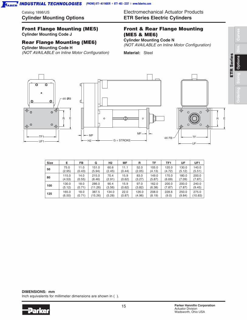
Front Flange Mounting (ME5)Cylinder Mounting Code J
Rear Flange Mounting (ME6)Cylinder Mounting Code H(NOT AVAILABLE on Inline Motor Configuration)
Size E FB G H2 MF R TF TF1 UF UF1
5075.0 11.0 151.0 60.6 11.1 52.0 105.0 120.0 130.0 140.0
(2.95) (0.43) (5.94) (2.45) (0.44) (2.05) (4.13) (4.72) (5.12) (5.51)
80115.0 14.0 215.0 70.4 15.9 83.0 149.0 170.0 180.0 200.0(4.53) (0.55) (8.46) (2.91) (0.62) (3.27) (5.87) (6.69) (7.09) (7.87)
100130.0 18.0 286.0 90.4 15.9 97.0 162.0 200.0 200.0 240.0(5.12) (0.71) (11.26) (3.56) (0.62) (3.82) (6.38) (7.87) (7.87) (9.45)
125165.0 18.0 387.5 134.0 22.0 126.0 208.0 228.6 250.0 275.0(6.50) (0.71) (15.26) (5.28) (0.87) (4.96) (8.19) (9.0) (9.84) (10.83)
Cylinder Mounting Options
4X FB
UF
TF
R E
MFMF
H2 G + STROKEUF1
TF1
R E
4X ØFB
Front & Rear Flange Mounting(ME5 & ME6)Cylinder Mounting Code N(NOT AVAILABLE on Inline Motor Configuration)
Material: Steel
16 Parker Hannifin CorporationActuator DivisionWadsworth, Ohio USA
Electromechanical Actuator ProductsETR Series Electric Cylinders
Catalog 1898/US
ETB Series
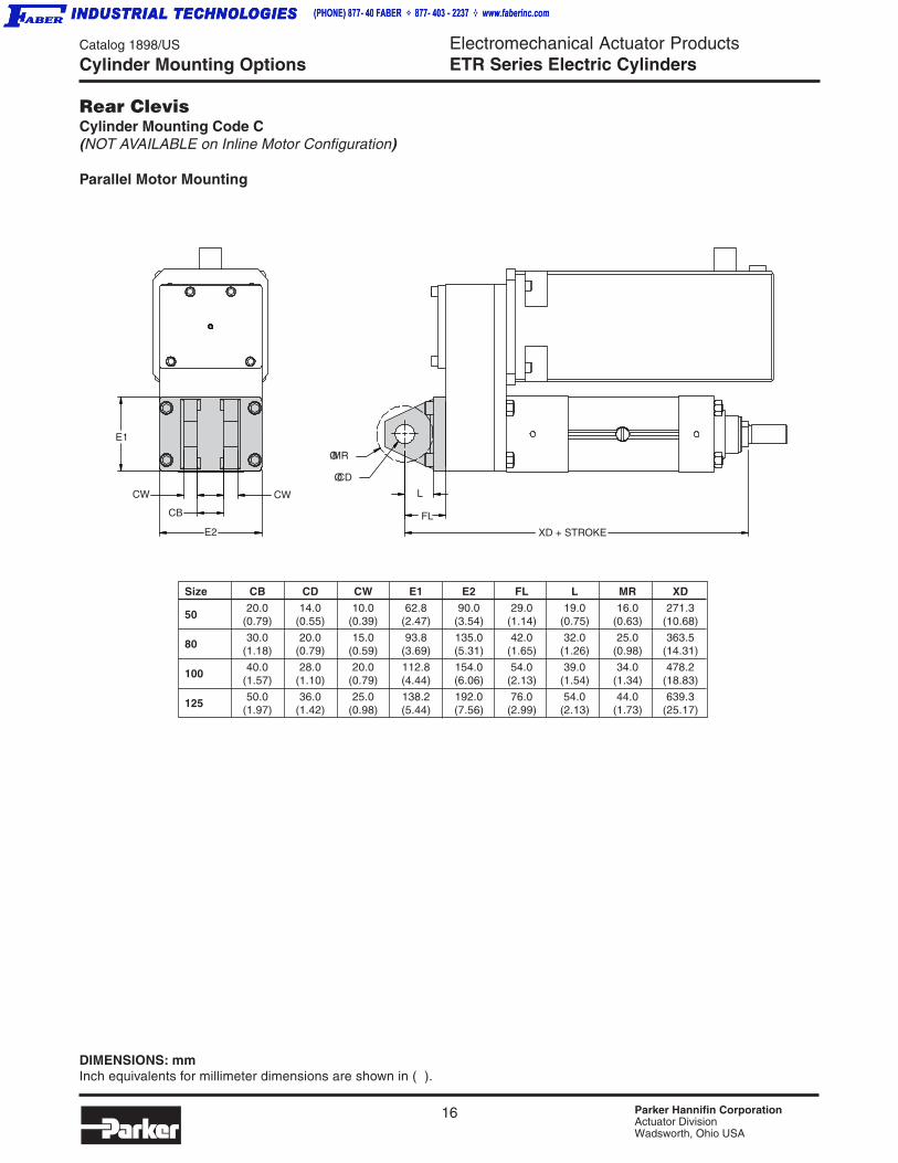
Rear ClevisCylinder Mounting Code C(NOT AVAILABLE on Inline Motor Configuration)
Parallel Motor Mounting
E1
CW
E2
CB
CW
ØCD
ØMR
FL
L
XD + STROKE
Size CB CD CW E1 E2 FL L MR XD
5020.0 14.0 10.0 62.8 90.0 29.0 19.0 16.0 271.3
(0.79) (0.55) (0.39) (2.47) (3.54) (1.14) (0.75) (0.63) (10.68)
80 30.0 20.0 15.0 93.8 135.0 42.0 32.0 25.0 363.5(1.18) (0.79) (0.59) (3.69) (5.31) (1.65) (1.26) (0.98) (14.31)
100 40.0 28.0 20.0 112.8 154.0 54.0 39.0 34.0 478.2(1.57) (1.10) (0.79) (4.44) (6.06) (2.13) (1.54) (1.34) (18.83)
125 50.0 36.0 25.0 138.2 192.0 76.0 54.0 44.0 639.3(1.97) (1.42) (0.98) (5.44) (7.56) (2.99) (2.13) (1.73) (25.17)
DIMENSIONS: mmInch equivalents for millimeter dimensions are shown in ( ).
Cylinder Mounting Options

Catalog 1898/US
Basic DimensionsElectromechanical Actuator ProductsETR Series Electric Cylinders
17 Parker Hannifin CorporationActuator DivisionWadsworth, Ohio USA
ET
R S
eri
es
Cu
rves
Siz
ing
Dim
.O
rder
ing
Op
tio
ns
DIMENSIONS: mmInch equivalents for millimeter dimensions are shown in ( ).
Cylinder Mounting Options
Foot Side Lug MountingCylinder Mounting Code G(Inline or Parallel Motor Configuration)
Material: Zinc Plated Steel
Size C TG UF FB TM MF WH
50109.0 83.0 103.0 11.0 24.0 12.5 52.2(4.29) (3.27) (4.06) (0.43) (0.94) (0.49) (2.06)
80170.0 124.0 161.0 18.0 32.0 26.0 63.0(6.66) (4.88) (6.34) (0.71) (1.26) (1.02) (2.48)
100 220.0 149.0 186.0 18.0 42.5 26.0 85.0(8.66) (5.87) (7.32) (0.71) (1.67) (1.02) (3.35)
125 304.3 172.0 216.0 26.0 66.0 32.0 96.8(11.98) (6.77) (8.50) (1.02) (2.60) (1.26) (3.81)
TMØFB
UF TG
C + STROKE WH MF
Tie Rods Extended (MX3)Cylinder Mounting Code T(Inline or Parallel Motor Configuration)
J 4X PP TG
TGØB
Size TG B J PP
5041.7 40.0 35.0
M8 x 1.0(1.64) (1.57) (1.38)
8064.3 50.0 46.0
M12 x 1.25(2.53) (1.97) (1.81)
10082.7 65.0 59.0
M12 x 1.25(3.26) (2.56) (2.32)
12596.9 90.0 59.0
M16 x 1.5(3.81) (3.54) (2.32)

18 Parker Hannifin CorporationActuator DivisionWadsworth, Ohio USA
Electromechanical Actuator ProductsETR Series Electric Cylinders
Catalog 1898/US
ETB Series
MaleRod End Code M or K
FemaleRod End Code F
"M" Standard Male - Metric Rod Thread
Cylinder AM ØB KK KV ØMM VE WH
ETR5032.0 40.0
M14 x 1.517.0 25.0 16.0 40.2
(1.26) (1.57) (0.67) (0.98) (0.63) (1.58)
ETR8040.0 49.9
M20 x 1.522.0 35.0 20.0 47.0
(1.57) (1.97) (0.87) (1.38) (0.79) (1.85)
ETR100
54.0 642 M27 x 2
27.0 50.0 20.0 63.7(2.13) (2.53) (1.06) (1.97) (0.79) (2.51)
ETR125 71.5 90.0
M33 x 241.0 70.0 20.0 63.8
(2.82) (3.54) (1.61) (2.75) (0.79) (2.51)
"K" Optional Male - Imperial Rod Thread
Cylinder AM ØB KK KV ØMM VE WH
ETR50 32.0 40.0
9/16-1817.0 25.0 16.0 40.2
(1.26) (1.57) (0.67) (0.98) (0.63) (1.58)
ETR8040.0 50.0
3/4-1622.0 35.0 20.0 47.0
(1.57) (1.97) (0.87) (1.38) (0.79) (1.85)
ETR10054.0 65.0
1-1427.0 50.0 20.0 63.7
(2.13) (2.56) (1.06) (1.97) (0.79) (2.51)
ETR125 71.5 90.0
1 1/4-1241.0 70.0 20.0 63.8
(2.82) (3.54) (1.61) (2.75) (0.79) (2.51)
"F" Female
Cylinder AM øB KK KV øMM WH
ETR50 25.0 40.0
M14 x 1.5 20.0 25.0 50.0
(0.98) (1.57) (.79) (0.98) (1.96)
ETR80 30.0 50.0
M20 x 1.5 26.0 35.0 59.0
(1.18) (1.97) (1.02) (1.38) (2.32)
ETR100 40.0 65.0
M27 x 2 37.0 50.0 73.0
(1.57) (2.56) (1.46) (1.97) (2.87)
ETR125 50.3 90.0
M33 x 255.0 70.0 104.5
(1.98) (3.54) (2.17) (2.76) (4.11)
Rod End Options
DIMENSIONS: mmInch equivalents for millimeterdimensions are shown in ( ).
DIMENSIONS: mmInch equivalents for millimeterdimensions are shown in ( ).
WH AM KV
KK
ØBØMM
VE
AM
KV (FLATS)
KK
ØBØMM
WH
Catalog 1898/US
Basic DimensionsElectromechanical Actuator ProductsETR Series Electric Cylinders
19 Parker Hannifin CorporationActuator DivisionWadsworth, Ohio USA
ET
R S
eri
es
Cu
rves
Siz
ing
Dim
.O
rder
ing
Op
tio
ns
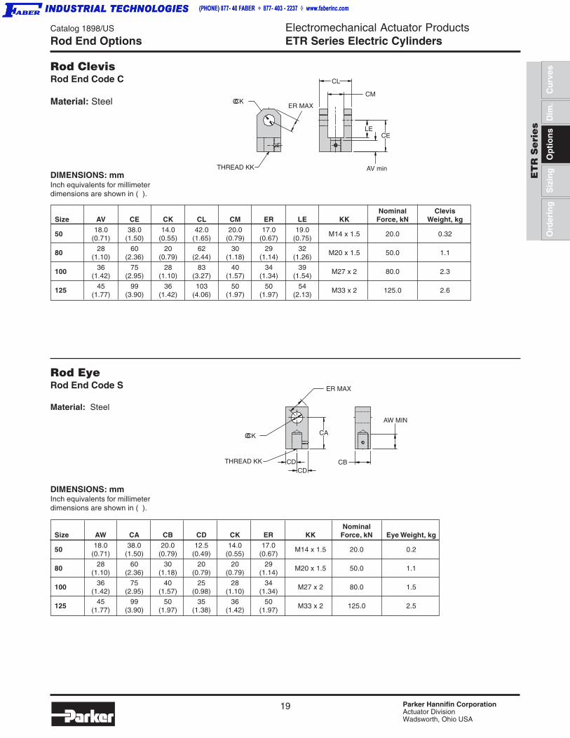
Rod EyeRod End Code S
Material: Steel
Rod ClevisRod End Code C
Material: Steel
DIMENSIONS: mmInch equivalents for millimeterdimensions are shown in ( ).
Nominal ClevisSize AV CE CK CL CM ER LE KK Force, kN Weight, kg
50 18.0 38.0 14.0 42.0 20.0 17.0 19.0M14 x 1.5 20.0 0.32
(0.71) (1.50) (0.55) (1.65) (0.79) (0.67) (0.75)
80 28 60 20 62 30 29 32M20 x 1.5 50.0 1.1
(1.10) (2.36) (0.79) (2.44) (1.18) (1.14) (1.26)
100 36 75 28 83 40 34 39M27 x 2 80.0 2.3
(1.42) (2.95) (1.10) (3.27) (1.57) (1.34) (1.54)
125 45 99 36 103 50 50 54M33 x 2 125.0 2.6
(1.77) (3.90) (1.42) (4.06) (1.97) (1.97) (2.13)
NominalSize AW CA CB CD CK ER KK Force, kN Eye Weight, kg
50 18.0 38.0 20.0 12.5 14.0 17.0M14 x 1.5 20.0 0.2
(0.71) (1.50) (0.79) (0.49) (0.55) (0.67)
80 28 60 30 20 20 29M20 x 1.5 50.0 1.1
(1.10) (2.36) (1.18) (0.79) (0.79) (1.14)
100 36 75 40 25 28 34M27 x 2 80.0 1.5
(1.42) (2.95) (1.57) (0.98) (1.10) (1.34)
12545 99 50 35 36 50
M33 x 2 125.0 2.5(1.77) (3.90) (1.97) (1.38) (1.42) (1.97)
Rod End Options
DIMENSIONS: mmInch equivalents for millimeterdimensions are shown in ( ).
ER MAX
CA
CB
AW MIN
THREAD KK
ØCK
CDCD
ØCKER MAX
THREAD KK
CL
CM
CELE
AV min
20 Parker Hannifin CorporationActuator DivisionWadsworth, Ohio USA
Electromechanical Actuator ProductsETR Series Electric Cylinders
Catalog 1898/US
ETB SeriesEnvironmental Considerations
The ETR Series Electric Cylinder features a durable design, but its useful life may be compromised byenvironmental factors. Temperature, humidity and particle contamination can affect an actuator’s performanceand useful life. Both drive system types (inline and parallel) provide basic protection for the drive transmissionand bearings.
ETR Series Protection Features• Rod Combination Lip and Wiper Seal – prevents particle penetration and
keeps lubricant inside the cylinder body.
• Stainless Steel Rod – Ground and polished, the thrust tube supports thedrive screw and resists corrosion.
• Anodized Cylinder Body – Clear hard anodize coating resists corrosion.
Temperature
Temperature Range: 0°C to 60°C (32°F to 140°F)
Extreme temperatures create tolerance problems due to the different thermal expansion coefficients of aluminumand steel. Please consult the factory if your application exceeds the temperature range above.
HumidityETR Series actuators are designed to provide basic protection against humidity. Protection is improved with theintroduction of an optional breather tube. The user supplied positive pressure keeps moisture outside of theactuator body. Alternatively, the breather tube may be vented to a non-humid environment away from theapplication.
Particle ContaminationETR Series products are enclosed and sealed. This generally provides good protection against particle contami-nants. If particles are especially small, a breather tube may be fitted to pressurize the actuator body or vent it.
LiquidsPlease consult the factory if the actuator is directly exposed to liquids, in particular aggressive fluids, or if theactuator is in a particularly wet environment.

Catalog 1898/US
Basic DimensionsElectromechanical Actuator ProductsETR Series Electric Cylinders
21 Parker Hannifin CorporationActuator DivisionWadsworth, Ohio USA
ET
R S
eri
es
Cu
rves
Siz
ing
Dim
.O
rder
ing
Op
tio
ns
Special Rod SealsSubstances in the application environment or the environ-ment itself may unfavorably react with the combination lipand wiper seal on the thrust tube (rod). Special materialsare available to suit most applications.
High Temperature ModificationsAluminum and steel have different thermal expansioncoefficients. It may be necessary to modify the fittolerances on certain parts to accommodate extremetemperatures. Contact the factory if the applicationenvironment exceeds the recommended temperaturerange.
TransducersSpecial transducers are made for a variety of demandingapplications and may involve miniature scale or highcapacities. Parker Actuator has the ability to integratedesign and manufacture these units into the ETR Rollerscrew with relatively short lead times.
• Fatigue rated
• Low height
• Guaranteed maximum off-centerload and moment error
• Static error band.03-.06%
• Low Creep
• Low Sensitivity to magnetic fields
• Temperature compensated
• Bayonet connector
• Internal/External configuration
Bellows CouplingBellows coupling will help provide "0" backlash in mostapplications. Consult the Actuator Division Application groupfor selecting the right coupling for the application.
Brake OptionConsult the Application Department for a brake mountedto the screw.
Bellows (Rod Boot) OptionProtect the stainlesssteel thrust tube with ahypalon/polyester rodboot, or bellows. Thebellows option is tiedon both ends andshields the thrust tubefrom splatter. Specialbellows installationsare available for weldsplatter.
Extended and Non-StandardStroke LengthsWhen high linear speed is not crucial to the performanceof the system, it may be possible to extend the standardlength of any size actuator. Screw critical speed is afunction of the diameter of the screw and the distancebetween its bearing supports. Additionally, non-standardor intermediate stroke lengths are available for a nominalcharge. Consult the factory for any special stroke needs.
Special LubricantsThe Actuator Division can provide special lubrication fordrive screws and thrust tubes as specified by the cus-tomer. Non-silicon based greases are available for cleanroom and vacuum-rated applications.
Breather Tube OptionThe aluminum actuator housing is an ideal platform forthe installation of air fittings. Breather tubes may be fittedfor user provided positive pressurization (air purge) orvacuum to minimize particle contamination.
Oil LubricationExtra lubrication port for continual oil cycling will providemaximum speed for the ETR linear actuators. ConsultApplication Department for further assistance.
Special Modifications

22 Parker Hannifin CorporationActuator DivisionWadsworth, Ohio USA
Catalog 1898/US
EngElectromechanical Actuator ProductsETR Series Electric Cylinders
Electric Cylinder Sizing and Selection
CalculateThrust
CalculateMotionProfile
SelectETR Series
Size and Screw
Refer to Performance Data
CalculateMotor Torqueand Velocity
AnalyzeInertias
CalculateLife
Expectancy
DevelopModel
Number
Select Motor System
Sizing Index
A number of steps are required to properly size and select an ETR cylinder. The flow chart highlights these steps, which areexplained in more detail on the following pages.
Contents
Sizing and SelectionThrust calculation ............................................................ 23Motion Profile Calculations ............................................. 24Selecting Size and Screw Pitch ...................................... 24Selecting Motor System Using ETR Curves ................... 25Sizing a Motor
Critical Speed .............................................................. 26Torque Requirements .................................................. 27Breakaway Torque ....................................................... 29Maximum Speed.......................................................... 29System Inertia ............................................................. 30Timing Belt .................................................................. 32
Calculate Life Expectancy ............................................... 32
Technical DataRod Side Loading ........................................................... 34Weights ........................................................................... 36
Technical AssistanceApplication Fax Form ...................................................... 37
23 Parker Hannifin CorporationActuator DivisionWadsworth, Ohio USA
Catalog 1898/US
EngElectromechanical Actuator ProductsETR Series Electric Cylinders
ET
R S
eri
es
Cu
rves
Siz
ing
Dim
.O
rder
ing
Op
tio
ns
Determining the proper size, screw type and pitch and motor system requires that the application developer pay close attentionto the application parameters. The following step process provides a thorough guide to ETR Series size and selection.
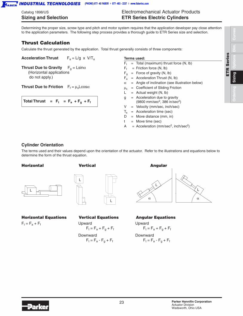
Thrust CalculationCalculate the thrust generated by the application. Total thrust generally consists of three components:
Acceleration Thrust Fa = L/g x V/Ta
Thrust Due to Gravity Fg = Lsinα (Horizontal applications do not apply.)
Thrust Due to Friction Ff = µsLcosα
Total Thrust = Ft = Fa + Fg + Ff
Cylinder OrientationThe terms used and their values depend upon the orientation of the actuator. Refer to the illustrations and equations below todetermine the form of the thrust equation.
Horizontal Vertical Angular
Horizontal Equations Vertical Equations Angular EquationsFt = Fa + Ff Upward Upward
Ft = Fa + Fg + Ff Ft = Fa + Fg + Ff
Downward DownwardFt = Fa - Fg + Ff Ft = Fa - Fg + Ff
Terms used:Ft = Total (maximum) thrust force (N, lb)Ff = Friction force (N, lb)Fg = Force of gravity (N, lb)Fa = Acceleration Thrust (N, lb)α = Angle of inclination (see illustration below)µs = Coefficient of Sliding FrictionL = Actual weight (N, lb)g = Acceleration due to gravity
(9800 mm/sec2, 386 in/sec2)V = Velocity (mm/sec, inch/sec)Ta = Acceleration time (sec)D = Move distance (mm, in)t = Move time (sec)A = Acceleration (mm/sec2, inch/sec2)
Sizing and Selection
L
L
L
L L
αα
24 Parker Hannifin CorporationActuator DivisionWadsworth, Ohio USA
Catalog 1898/US
EngElectromechanical Actuator ProductsETR Series Electric Cylinders
t/3 t/3t/3
V
t
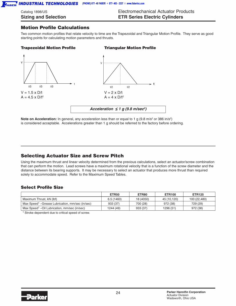
Motion Profile CalculationsTwo common motion profiles that relate velocity to time are the Trapezoidal and Triangular Motion Profile. They serve as goodstarting points for calculating motion parameters and thrusts.
Trapezoidal Motion Profile Triangular Motion Profile
V = 1.5 x D/t V = 2 x D/tA = 4.5 x D/t2 A = 4 x D/t2
Acceleration ≤≤≤≤≤ 1 g (9.8 m/sec2)
Note on Acceleration: In general, any acceleration less than or equal to 1 g (9.8 m/s2 or 386 in/s2)is considered acceptable. Accelerations greater than 1 g should be referred to the factory before ordering.
Selecting Actuator Size and Screw PitchUsing the maximum thrust and linear velocity determined from the previous calculations, select an actuator/screw combinationthat can perform the motion. Lead screws have a maximum rotational velocity that is a function of the screw diameter and thedistance between its bearing supports. It may be necessary to select an actuator that produces more thrust than requiredsolely to accommodate speed. Refer to the Maximum Speed Tables.
Select Profile Size
ETR50 ETR80 ETR100 ETR125Maximum Thrust, kN (lbf) 6.5 (1460) 18 (4050) 45 (10,120) 100 (22,480)
Max Speed1 – Grease Lubrication, mm/sec (in/sec) 933 (37) 700 (28) 972 (38) 729 (29)
Max Speed1 – Oil Lubrication, mm/sec (in/sec) 1244 (49) 933 (37) 1296 (51) 972 (38)1 Stroke dependent due to critical speed of screw.
Sizing and Selection
t/2 t/2
V
t
25 Parker Hannifin CorporationActuator DivisionWadsworth, Ohio USA
Catalog 1898/US
EngElectromechanical Actuator ProductsETR Series Electric Cylinders
ET
R S
eri
es
Cu
rves
Siz
ing
Dim
.O
rder
ing
Op
tio
ns
Sizing and Selection
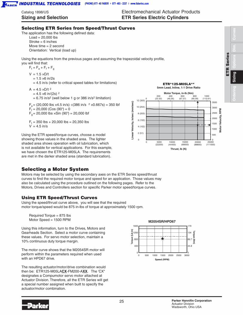
Selecting ETR Series from Speed/Thrust CurvesThe application has the following defined data:
Load = 20,000 lbsStroke = 6 inchesMove time = 2 secondOrientation: Vertical (load up)
Using the equations from the previous pages and assuming the trapezoidal velocity profile,you will find that:
Ft = Fa + Ff + Fg
V = 1.5 × D/t= 1.5 × 6 in/2s= 4.5 in/s (refer to critical speed tables for limitations)
A = 4.5 × D/t 2
= 4.5 × 6 in/(2s) 2
= 6.75 in/s2 (well below 1 g or 386 in/s2 limitation)
Fa = (20,000 lbs × 4.5 in/s) ÷ (386 in/s 2 × 0.667s) = 350 lbfFf = 20,000 (Cos (90°) = 0Fg = 20,000 lbs × Sin (90°) = 20,000 lbf
Ft = 350 lbs + 20,000 lbs = 20,350 lbsV = 4.5 in/s
Using the ETR speed/torque curves, choose a modelshowing those values in the shaded area. The lightershaded area shows operation with oil lubrication, whichis not available for vertical applications. For this example,we have chosen the ETR125-M05LA. The requirementsare met in the darker shaded area (standard lubrication).
Selecting a Motor SystemMotors may be selected by using the secondary axes on the ETR Series speed/thrustcurves to find the required motor torque and speed for an application. Those values mayalso be calculated using the procedure outlined on the following pages. Refer to theMotors, Drives and Controllers section for specific Parker motor speed/torque curves.
Using ETR Speed/Thrust CurvesUsing the speed/thrust curve above, you will see that the requiredmotor torque/speed would be 875 in-lbs of torque at approximately 1500 rpm.
Required Torque = 875 lbsMotor Speed = 1500 RPM
Using this information, turn to the Drives, Motors andGearheads Section. Select a motor curve containingthese values. For servo motor selection, maintain a10% continuous duty torque margin.
The motor curve shows that the M2054SR motor willperform within the parameters required when usedwith an HPD67 drive.
The resulting actuator/motor/drive combination wouldthen be: ETR125-M05LACX-FM200-AXX. The 'CX"designates a Compumotor servo motor attached atActuator Division. Therefore, all the ETR Series will geta special number assigned when built to specify theactuator/motor combination.
0
Thrust, lb (N)
Lin
earV
elo
city
, in
/sec
(m
m/s
ec)
ETR*125-M05LA**5mm Lead, Inline, 1:1 Drive Ratio
Mo
torV
elo
city
,RP
M
Motor Torque, in-lb (Nm)
3500
3000
2500
2000
0
200(22.52)
400(45.05)
800(90.09)
5000(22200)
20000(88800)
25000(111000)
15000(66600)
10000(44400)
600(67.57)
1500
1000
500
4 (102)
8 (203)
12 (305)
2 (51)
6 (152)
10 (254)
0
01000
(112.61)
0 500 1000 1500 2000 2500 30000
400
800
1200
1600
0
44.8
89.7
134
179
M2054SR/HPD67
Speed (RPM)
Torq
ue
(Lb
-in
) Torq
ue (N
m)

26 Parker Hannifin CorporationActuator DivisionWadsworth, Ohio USA
Catalog 1898/US
EngElectromechanical Actuator ProductsETR Series Electric Cylinders
Actuator (Lubrication) 0 50 100 150 200 300 450 600 750 1000
ETR50-M05 (Oil) 778 778 778 778 778 778 670 396 262 —
ETR50-M05 (Grease) 583 583 583 583 583 583 583 396 262 —
ETR50-M08 (Oil) 1244 1244 1244 1244 1244 1244 1071 634 419 —
ETR50-M08 (Grease) 933 933 933 933 933 933 933 634 419 —
ETR80-M05 (Oil) 467 467 467 467 467 467 467 467 436 —
ETR80-M05 (Grease) 350 350 350 350 350 350 350 350 350 —
ETR80-M10 (Oil) 933 933 933 933 933 933 933 933 872 —
ETR80-M10 (Grease) 700 700 700 700 700 700 700 700 700 —
ETR100-M05 (Oil) 324 324 324 324 324 324 324 324 324 324
ETR100-M05 (Grease) 243 243 243 243 243 243 243 243 243 243
ETR100-M10 (Oil) 648 648 648 648 648 648 648 648 648 648
ETR100-M10 (Grease) 486 486 486 486 486 486 486 486 486 486
ETR100-M20 (Oil) 1296 1296 1296 1296 1296 1296 1296 1296 1296 1296
ETR100-M20 (Grease ) 972 972 972 972 972 972 972 972 972 972
ETR125-M05 (Oil) 243 243 243 243 243 243 243 243 243 243
ETR125-M05 (Grease) 182 182 182 182 182 182 182 182 182 182
ETR125-M10 (Oil) 486 486 486 486 486 486 486 486 486 486
ETR125-M10 (Grease) 365 365 365 365 365 365 365 365 365 365
ETR125-M20 (Oil) 972 972 972 972 972 972 972 972 972 972
ETR125-M20 (Grease) 729 729 729 729 729 729 729 729 729 729
IMPERIALMaximum Speed (in/sec) vs. Stroke (mm)Actuator (Lubrication) 0 50 100 150 200 300 450 600 750 1000
ETR50-M05 (Oil) 31 31 31 31 31 31 26 16 10 —
ETR50-M05 (Grease) 23 23 23 23 23 23 23 16 10 —
ETR50-M08 (Oil) 49 49 49 49 49 49 42 25 16 —
ETR50-M08 (Grease) 37 37 37 37 37 37 37 25 16 —
ETR80-M05 (Oil) 18 18 18 18 18 18 18 18 17 —
ETR80-M05 (Grease) 14 14 14 14 14 14 14 14 14 —
ETR80-M10 (Oil) 37 37 37 37 37 37 37 37 34 —
ETR80-M10 (Grease) 28 28 28 28 28 28 28 28 28 —
ETR100-M05 (Oil) 13 13 13 13 13 13 13 13 13 13
ETR100-M05 (Grease) 10 10 10 10 10 10 10 10 10 10
ETR100-M10 (Oil) 26 26 26 26 26 26 26 26 26 26
ETR100-M10 (Grease) 19 19 19 19 19 19 19 19 19 19
ETR100-M20 (Oil) 51 51 51 51 51 51 51 51 51 51
ETR100-M20 (Grease) 38 38 38 38 38 38 38 38 38 38
ETR125-M05 (Oil) 10 10 10 10 10 10 10 10 10 10
ETR125-M05 (Grease) 7 7 7 7 7 7 7 7 7 7
ETR125-M10 (Oil) 19 19 19 19 19 19 19 19 19 19
ETR125-M10 (Grease) 14 14 14 14 14 14 14 14 14 14
ETR125-M20 (Oil) 38 38 38 38 38 38 38 38 38 38
ETR125-M20 (Grease) 29 29 29 29 29 29 29 29 29 29
Calculating Torque and Speed
A. Check the maximum speedAs the length of the lead screw increases, mechanical limitations prevent it from attaining speeds of shorter screws. Harmonicvibrations at certain rotational speeds are evident in all screw driven systems. Operation at or above this “critical speed” wi llcause the screw to “whip”, which will in turn damage the screw.
The following charts show the speed limitations of ETR Series Electric Cylinders due to length. Use the Maximum SpeedCharts to determine which screw pitch will accommodate the velocity requirement for the actuator size selected. It may benecessary to increase actuator size to accommodate maximum speed. Remember that lead will affect torque, inertia andspeed requirements for the motor. Also, at high dynamic loads, the speed is limited even further than what is shown. Consultfactory for maximum speeds when under high loads.
METRICMaximum Speed (mm/sec) vs Stroke (mm)
Selecting Motor System

27 Parker Hannifin CorporationActuator DivisionWadsworth, Ohio USA
Catalog 1898/US
EngElectromechanical Actuator ProductsETR Series Electric Cylinders
ET
R S
eri
es
Cu
rves
Siz
ing
Dim
.O
rder
ing
Op
tio
ns
B. Determine the motor torque requirements
1. Maximum Torque
T = Thrust x Lead ηs x ηb x 2π x Ratio
Where:T = Input torque required, Nm (in-lb)Lead = Screw lead (in/Rev) – see tableThrust = Calculated thrust value in N (lbf)
= Fa + Fg + Ff
Fa (acceleration thrust)= Load / (9800mm/sec2) × Velocity/acceleration time
Fg (force of gravity) = Load × sin αFf (friction force) = µs (see table) × Load × cos α
η η η η ηb = Timing belt efficiency coefficient:for parallel driven versions, typically 0.9 (or 90%)for inline versions use 1.0
ηηηηηs = Screw efficiency coefficient
Ratio = Drive ratio (if reducer is used)
Friction CoefficientMaterial(dry contactunless noted) µs
Steel on steel 0.80
Steel on steel (lubricated) 0.16
Aluminum on steel 0.45
Copper on steel 0.22
Brass on steel 0.35
Teflon on steel 0.04
Screw EfficiencyActuator Lead Coefficient, ηηηηηs
ETR50-M05 5mm 0.89
ETR50-M08 8mm 0.90
ETR80-M05 5mm 0.87
ETR80-M10 10mm 0.89
ETR100-M05 5mm 0.84
ETR100-M10 10mm 0.88
ETR100-M20 20mm 0.90
ETR125-M05 5mm 0.82
ETR125-M10 10mm 0.87
ETR125-M20 20mm 0.89
Screw Properties
Selecting Motor System

28 Parker Hannifin CorporationActuator DivisionWadsworth, Ohio USA
Catalog 1898/US
EngElectromechanical Actuator ProductsETR Series Electric Cylinders
To calculate the continuous (rms) torque:
Trms = [ Σ Ti2ti / Σ ti ]
Where Ti = Torque required over time interval ti (Nm, in-lb)ti = Time interval i (sec)
Example: For a typical trapezoidal profile, let
T1 = acceleration torque = 1000 Nmt1 = 1 sec
T2 = torque at a constant speed (friction) = 25 Nmt2 = 1 sec
T3 = deceleration torque = 1000-25 = 975 Nmt3 = 1 sec
T4 = torque at rest = 0 Nm (horizontal orientation)
t4 = 10 sec
When viewing servo motor speed-torque curves, let Trms represent the maximum continous torque value, while Tmax mayrepresent the peak torque value.
Terms used:Lead = Screw lead (mm/rev) – see page 27
VL = Maximum linear velocity in m/s (in/sec) Ratio = Reduction ratio, if any (i.e. 2:1, Ratio=2) Speed = Required motor speed in rev/sec
This would represent a single duty cycle.To calculate Trms.
Trms = [((1000 Nm)2x 1 sec)+((25 Nm)2x 1sec)+((975 Nm)2x 1 sec)+(0 Nm)2x10 sec)] /[1+1+1+10 sec]
Trms = 387 Nm
2. Continuous Torque (Servo systems only)
With servo motors, it is important to understand the relationship between peak torque andcontinuous torque. Continuous or rms torque refers to the torque a servo motor systemcan produce continuously, or at 100% duty cycle. Peak torque refers to torque produced inintermittent time quantities, generally less than 5 seconds. This allows the user to better sizethe servo motor required based on what the actual torque needs are for the application. Themaximum torque calculated in the previous section will represent the peak torque require-ment. To determine the continuous torque requirement, first establish a sequence of use overa given duty cycle.It is necessary to calculate the torque required at different instances of thrust. There are threegeneral types of torque, and they correspond to thrusts calculated earlier:
Acceleration torque: Torque when generating total thrust Ft (This is normally the maxi-mum torque required.)
Constant speed torque: Torque when generating friction and gravity thrust (Ff + Fg)
Static torque: Torque when holding a static load (typically gravity thrust Fg)
Selecting Motor System
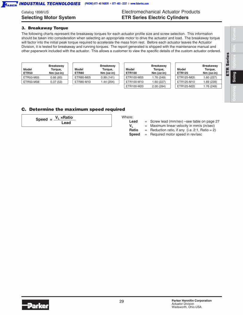
29 Parker Hannifin CorporationActuator DivisionWadsworth, Ohio USA
Catalog 1898/US
EngElectromechanical Actuator ProductsETR Series Electric Cylinders
ET
R S
eri
es
Cu
rves
Siz
ing
Dim
.O
rder
ing
Op
tio
ns
C. Determine the maximum speed required
Speed = VL × Ratio Lead
Where:Lead = Screw lead (mm/rev) – see table on page 27VL = Maximum linear velocity in mm/s (in/sec)Ratio = Reduction ratio, if any (i.e. 2:1, Ratio = 2)Speed = Required motor speed in rev/sec
BreakawayModel Torque,ETR50 Nm (oz-in)
ETR50-M05 0.66 (93)
ETR50-M08 0.37 (53)
BreakawayModel Torque,ETR80 Nm (oz-in)
ETR80-M05 0.99 (141)
ETR80-M10 1.44 (204)
BreakawayModel Torque,ETR125 Nm (oz-in)
ETR125-M05 1.60 (227)
ETR125-M10 1.69 (239)
ETR125-M20 1.76 (249)
BreakawayModel Torque,ETR100 Nm (oz-in)
ETR100-M05 1.76 (249)
ETR100-M10 1.60 (227)
ETR100-M20 2.00 (284)
3. Breakaway TorqueThe following charts represent the breakaway torques for each actuator profile size and screw selection. This informationshould be taken into consideration when selecting an appropriate motor to drive the actuator and load. The breakaway torquewill factor into the initial peak torque required to accelerate the mass from rest. Before each actuator leaves the ActuatorDivision, it is tested for breakaway and running torques. The report generated is shipped with the maintenance manual andother paperwork included with the actuator. This allows a customer to view the specific details of the custom actuator ordered.
Selecting Motor System
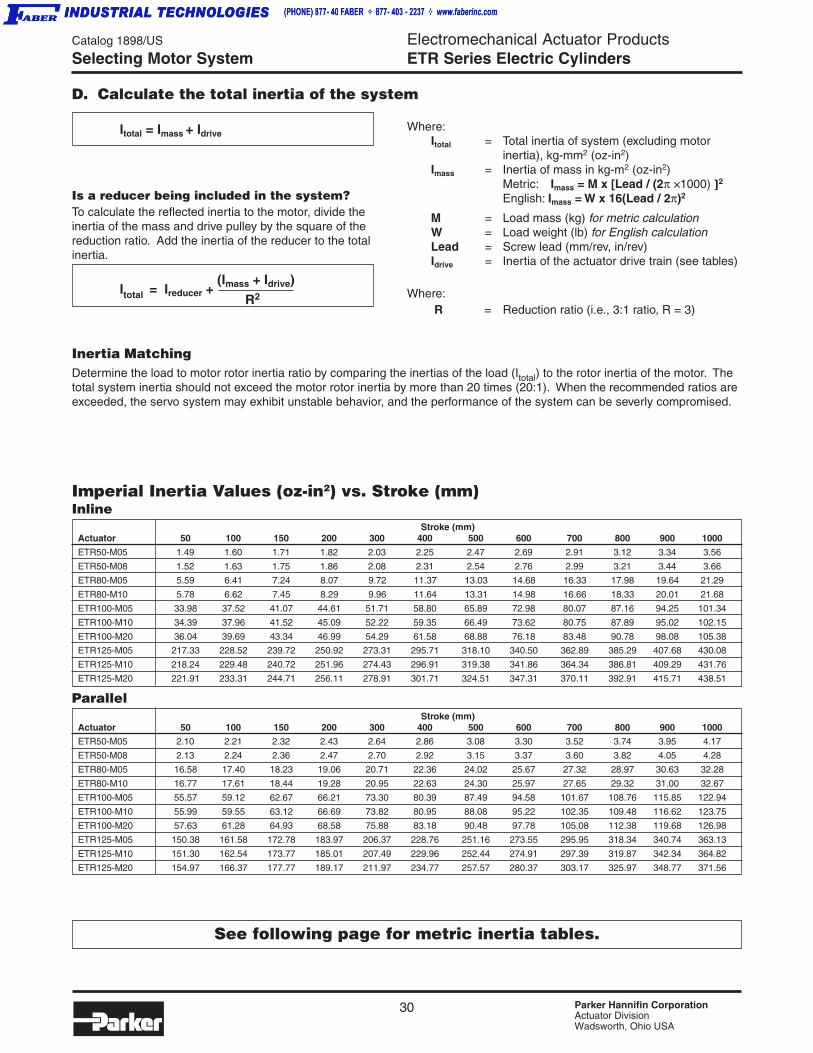
30 Parker Hannifin CorporationActuator DivisionWadsworth, Ohio USA
Catalog 1898/US
EngElectromechanical Actuator ProductsETR Series Electric Cylinders
Inertia MatchingDetermine the load to motor rotor inertia ratio by comparing the inertias of the load (Itotal) to the rotor inertia of the motor. Thetotal system inertia should not exceed the motor rotor inertia by more than 20 times (20:1). When the recommended ratios areexceeded, the servo system may exhibit unstable behavior, and the performance of the system can be severly compromised.
Where: R = Reduction ratio (i.e., 3:1 ratio, R = 3)
D. Calculate the total inertia of the system
Itotal = Imass + Idrive
Is a reducer being included in the system?To calculate the reflected inertia to the motor, divide theinertia of the mass and drive pulley by the square of thereduction ratio. Add the inertia of the reducer to the totalinertia.
Itotal = Ireducer + (Imass + Idrive)
R2
Selecting Motor System
Imperial Inertia Values (oz-in2) vs. Stroke (mm)Inline
Stroke (mm)Actuator 50 100 150 200 300 400 500 600 700 800 900 1000
ETR50-M05 1.49 1.60 1.71 1.82 2.03 2.25 2.47 2.69 2.91 3.12 3.34 3.56
ETR50-M08 1.52 1.63 1.75 1.86 2.08 2.31 2.54 2.76 2.99 3.21 3.44 3.66
ETR80-M05 5.59 6.41 7.24 8.07 9.72 11.37 13.03 14.68 16.33 17.98 19.64 21.29
ETR80-M10 5.78 6.62 7.45 8.29 9.96 11.64 13.31 14.98 16.66 18.33 20.01 21.68
ETR100-M05 33.98 37.52 41.07 44.61 51.71 58.80 65.89 72.98 80.07 87.16 94.25 101.34
ETR100-M10 34.39 37.96 41.52 45.09 52.22 59.35 66.49 73.62 80.75 87.89 95.02 102.15
ETR100-M20 36.04 39.69 43.34 46.99 54.29 61.58 68.88 76.18 83.48 90.78 98.08 105.38
ETR125-M05 217.33 228.52 239.72 250.92 273.31 295.71 318.10 340.50 362.89 385.29 407.68 430.08
ETR125-M10 218.24 229.48 240.72 251.96 274.43 296.91 319.38 341.86 364.34 386.81 409.29 431.76
ETR125-M20 221.91 233.31 244.71 256.11 278.91 301.71 324.51 347.31 370.11 392.91 415.71 438.51
Parallel Stroke (mm)
Actuator 50 100 150 200 300 400 500 600 700 800 900 1000
ETR50-M05 2.10 2.21 2.32 2.43 2.64 2.86 3.08 3.30 3.52 3.74 3.95 4.17
ETR50-M08 2.13 2.24 2.36 2.47 2.70 2.92 3.15 3.37 3.60 3.82 4.05 4.28
ETR80-M05 16.58 17.40 18.23 19.06 20.71 22.36 24.02 25.67 27.32 28.97 30.63 32.28
ETR80-M10 16.77 17.61 18.44 19.28 20.95 22.63 24.30 25.97 27.65 29.32 31.00 32.67
ETR100-M05 55.57 59.12 62.67 66.21 73.30 80.39 87.49 94.58 101.67 108.76 115.85 122.94
ETR100-M10 55.99 59.55 63.12 66.69 73.82 80.95 88.08 95.22 102.35 109.48 116.62 123.75
ETR100-M20 57.63 61.28 64.93 68.58 75.88 83.18 90.48 97.78 105.08 112.38 119.68 126.98
ETR125-M05 150.38 161.58 172.78 183.97 206.37 228.76 251.16 273.55 295.95 318.34 340.74 363.13
ETR125-M10 151.30 162.54 173.77 185.01 207.49 229.96 252.44 274.91 297.39 319.87 342.34 364.82
ETR125-M20 154.97 166.37 177.77 189.17 211.97 234.77 257.57 280.37 303.17 325.97 348.77 371.56
See following page for metric inertia tables.
Where:Itotal = Total inertia of system (excluding motor
inertia), kg-mm2 (oz-in2)Imass = Inertia of mass in kg-m2 (oz-in2)
Metric: Imass = M x [Lead / (2π × 1000) ]]]]]2
English: Imass = W x 16(Lead / 2π)2
M = Load mass (kg) for metric calculationW = Load weight (lb) for English calculationLead = Screw lead (mm/rev, in/rev)Idrive = Inertia of the actuator drive train (see tables)
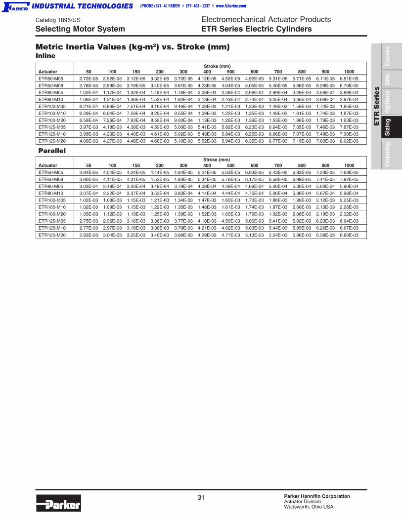
31 Parker Hannifin CorporationActuator DivisionWadsworth, Ohio USA
Catalog 1898/US
EngElectromechanical Actuator ProductsETR Series Electric Cylinders
ET
R S
eri
es
Cu
rves
Siz
ing
Dim
.O
rder
ing
Op
tio
ns
Selecting Motor System
Metric Inertia Values (kg-m2) vs. Stroke (mm)Inline
Stroke (mm)Actuator 50 100 150 200 300 400 500 600 700 800 900 1000
ETR50-M05 2.72E-05 2.92E-05 3.12E-05 3.32E-05 3.72E-05 4.12E-05 4.52E-05 4.92E-05 5.31E-05 5.71E-05 6.11E-05 6.51E-05
ETR50-M08 2.78E-05 2.99E-05 3.19E-05 3.40E-05 3.81E-05 4.23E-05 4.64E-05 5.05E-05 5.46E-05 5.88E-05 6.29E-05 6.70E-05
ETR80-M05 1.02E-04 1.17E-04 1.32E-04 1.48E-04 1.78E-04 2.08E-04 2.38E-04 2.68E-04 2.99E-04 3.29E-04 3.59E-04 3.89E-04
ETR80-M10 1.06E-04 1.21E-04 1.36E-04 1.52E-04 1.82E-04 2.13E-04 2.43E-04 2.74E-04 3.05E-04 3.35E-04 3.66E-04 3.97E-04
ETR100-M05 6.21E-04 6.86E-04 7.51E-04 8.16E-04 9.46E-04 1.08E-03 1.21E-03 1.33E-03 1.46E-03 1.59E-03 1.72E-03 1.85E-03
ETR100-M10 6.29E-04 6.94E-04 7.59E-04 8.25E-04 9.55E-04 1.09E-03 1.22E-03 1.35E-03 1.48E-03 1.61E-03 1.74E-03 1.87E-03
ETR100-M20 6.59E-04 7.26E-04 7.93E-04 8.59E-04 9.93E-04 1.13E-03 1.26E-03 1.39E-03 1.53E-03 1.66E-03 1.79E-03 1.93E-03
ETR125-M05 3.97E-03 4.18E-03 4.38E-03 4.59E-03 5.00E-03 5.41E-03 5.82E-03 6.23E-03 6.64E-03 7.05E-03 7.46E-03 7.87E-03
ETR125-M10 3.99E-03 4.20E-03 4.40E-03 4.61E-03 5.02E-03 5.43E-03 5.84E-03 6.25E-03 6.66E-03 7.07E-03 7.49E-03 7.90E-03
ETR125-M20 4.06E-03 4.27E-03 4.48E-03 4.68E-03 5.10E-03 5.52E-03 5.94E-03 6.35E-03 6.77E-03 7.19E-03 7.60E-03 8.02E-03
Parallel Stroke (mm)
Actuator 50 100 150 200 300 400 500 600 700 800 900 1000
ETR50-M05 3.84E-05 4.04E-05 4.24E-05 4.44E-05 4.84E-05 5.24E-05 5.63E-05 6.03E-05 6.43E-05 6.83E-05 7.23E-05 7.63E-05
ETR50-M08 3.90E-05 4.11E-05 4.31E-05 4.52E-05 4.93E-05 5.34E-05 5.76E-05 6.17E-05 6.58E-05 6.99E-05 7.41E-05 7.82E-05
ETR80-M05 3.03E-04 3.18E-04 3.33E-04 3.49E-04 3.79E-04 4.09E-04 4.39E-04 4.69E-04 5.00E-04 5.30E-04 5.60E-04 5.90E-04
ETR80-M10 3.07E-04 3.22E-04 3.37E-04 3.53E-04 3.83E-04 4.14E-04 4.44E-04 4.75E-04 5.06E-04 5.36E-04 5.67E-04 5.98E-04
ETR100-M05 1.02E-03 1.08E-03 1.15E-03 1.21E-03 1.34E-03 1.47E-03 1.60E-03 1.73E-03 1.86E-03 1.99E-03 2.12E-03 2.25E-03
ETR100-M10 1.02E-03 1.09E-03 1.15E-03 1.22E-03 1.35E-03 1.48E-03 1.61E-03 1.74E-03 1.87E-03 2.00E-03 2.13E-03 2.26E-03
ETR100-M20 1.05E-03 1.12E-03 1.19E-03 1.25E-03 1.39E-03 1.52E-03 1.65E-03 1.79E-03 1.92E-03 2.06E-03 2.19E-03 2.32E-03
ETR125-M05 2.75E-03 2.96E-03 3.16E-03 3.36E-03 3.77E-03 4.18E-03 4.59E-03 5.00E-03 5.41E-03 5.82E-03 6.23E-03 6.64E-03
ETR125-M10 2.77E-03 2.97E-03 3.18E-03 3.38E-03 3.79E-03 4.21E-03 4.62E-03 5.03E-03 5.44E-03 5.85E-03 6.26E-03 6.67E-03
ETR125-M20 2.83E-03 3.04E-03 3.25E-03 3.46E-03 3.88E-03 4.29E-03 4.71E-03 5.13E-03 5.54E-03 5.96E-03 6.38E-03 6.80E-03
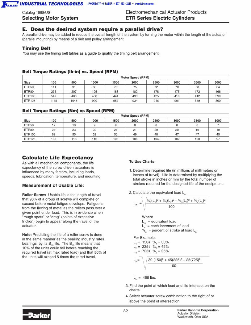
32 Parker Hannifin CorporationActuator DivisionWadsworth, Ohio USA
Catalog 1898/US
EngElectromechanical Actuator ProductsETR Series Electric Cylinders
100
For Example:L1 = 150# %1 = 30%L2 = 225# %2 = 45%L3 = 725# %3 = 25%
Lm= 30 (150)2 + 45(225)2 + 25(725)2
Lm = 466 lbs.
Motor Speed (RPM)
Size 100 500 1000 1500 2000 2500 3000 3500 5000
ETR50 111 91 83 78 75 72 70 68 64
ETR80 236 207 195 188 182 178 175 172 166
ETR100 547 486 460 444 433 425 418 412 399
ETR125 1175 1045 990 957 934 916 901 889 860
Belt Torque Ratings (Nm) vs Speed (RPM)Motor Speed (RPM)
Size 100 500 1000 1500 2000 2500 3000 3500 5000
ETR50 12 10 9 9 8 8 8 8 7
ETR80 27 23 22 21 21 20 20 19 19
ETR100 62 55 52 50 49 48 47 47 45
ETR125 133 118 112 108 106 104 102 100 97
Calculate Life ExpectancyAs with all mechanical components, the lifeexpectancy of the screw driven actuators isinfluenced by many factors, including loads,speeds, lubrication, temperature, and mounting.
Measurement of Usable Life:
Roller Screw: Usable life is the length of travelthat 90% of a group of screws will complete orexceed before metal fatigue develops. Fatigue isfrom the flexing of metal as the rollers pass over agiven point under load. This is in evidence when"rough spots" or "drag" (points of excessivefriction) begin to appear along the travel of theactuator.
Note: Predicting the life of a roller screw is donein the same manner as the bearing industry ratesbearings, by its B10 life. The B10 life means that10% of the units could fail before reaching therequired travel (at max rated load) and that 50% ofthe units will exceed 5 times the rated travel.
To Use Charts:
1. Determine required life (in millions of millimeters orinches of travel). Life is determined by multiplying thetotal stroke in inches or mm by the total number ofstrokes required for the designed life of the equipment.
2. Calculate the equivalent load Lm
3. Find the point at which load and life intersect on thecharts.
4. Select actuator screw combination to the right of orabove the point of intersection.
E. Does the desired system require a parallel drive?A parallel drive may be added to reduce the overall length of the system by turning the motor within the length of the actuator(parallel mounting) by means of a belt and pulley arrangement .
Timing Belt You may use the timing belt tables as a guide to qualify the timing belt arrangement.
Belt Torque Ratings (lb-in) vs. Speed (RPM)
Selecting Motor System
100Lm =
%1(L1)2 + %2(L2)
2 + %3(L3)2 + %n(Ln)
2
WhereLm = equivalent loadLn = each increment of load%n = percent of stroke at load Ln

33 Parker Hannifin CorporationActuator DivisionWadsworth, Ohio USA
Catalog 1898/US
EngElectromechanical Actuator ProductsETR Series Electric Cylinders
ET
R S
eri
es
Cu
rves
Siz
ing
Dim
.O
rder
ing
Op
tio
ns
Life Expectancy
1,000,000
100,000
1,000
100
10,000
10
0
1
2 4 6 8 10 12 140
1,000
100
10,000
10
1
100,000
1,000,000
0 10 20 30 40 50 60
M20
M10, M05
BallScrew
M08M05
BallScrew
ETR50 Life Expectancy
ETR100 Life Expectancy
Load, kN
Load, kN
Lif
e,km
of
trav
elL
ife,
kmo
f tr
avel
10
100
1,000
10,000
10 30 50 70 90 110 130 150 170
M10
Ball Screw
M20
M05
M10
M05
BallScrew
ETR80 Life Expectancy
ETR125 Life Expectancy
1
10
100
1,000
10,000
100,000
1,000,000
0 5 10 15 20 25 30
Load, kN
Load, kN
Lif
e,km
of
trav
elL
ife,
kmo
f tr
avel
NOTE: Ballscrew lines are for reference only.

34 Parker Hannifin CorporationActuator DivisionWadsworth, Ohio USA
Catalog 1898/US
EngElectromechanical Actuator ProductsETR Series Electric CylindersRod Side Loading
The ETR Series Electric Cylinder incorporates a generousrod bearing and four torlon bearing pads as the anti-rotateassembly. However, care should be taken to limit theamount of side loading exerted on the cylinder rod. Thecharts below show basic load data for various strokelengths of cylinders. Note that the load capacity increasesas the available stroke increases due to greater bearingseparation. For greater load capacity for a given applica-tion, a cylinder can be specified with a longer stroke, then"shortstroked" in the application. For example, an ETR50with 450 mm of stroke has a maximum load capacity of 41kg at full extension. An ETR50 with 600 mm of availablestroke, used in the same application, but only stroked to 450mm would have a maximum side load capacity of 17.5 kg.
To use chart:1. Find the chart and curve for the chosen model number
and maximum stroke.2. Find the corresponding maximum rod load permissible at
the desired stroke distance as measured from fullretraction.
3. Rod side load is assumed to be perpendicularly applieddirectly at the rod end.
Important: The side loading charted on these two pages canbe applied in any direction perpendicular to the thrust tube.
Stroke Position, mm (in)
ETR50 Rod End Load Capacity vs Stroke25
(55)
20(44)
15(33)
10(22)
5(11)L
oad
Cap
acit
y kg
(lb
)
100 mm
200 mm
300 mm
750 mm
0100(3.9)
200(7.9)
300(11.8)
400(15.7)
500(19.7)
600(23.6)
700(27.6)
0
50 mm
150 mm
450 mm600 mm
ETR80 Rod End Load Capacity vs Stroke50
(110)
40(88)
30(66)
10(22)
20(44)
50 mm
100 mm
150 mm
200 mm
300 mm
450 mm600 mm
750 mm0
100(3.9)
200(7.9)
300(11.8)
400(15.7)
500(19.7)
600(23.6)
700(27.6)
800(31.5)
0
Stroke Position, mm (in)
Lo
ad C
apac
ity,
kg
(lb
)
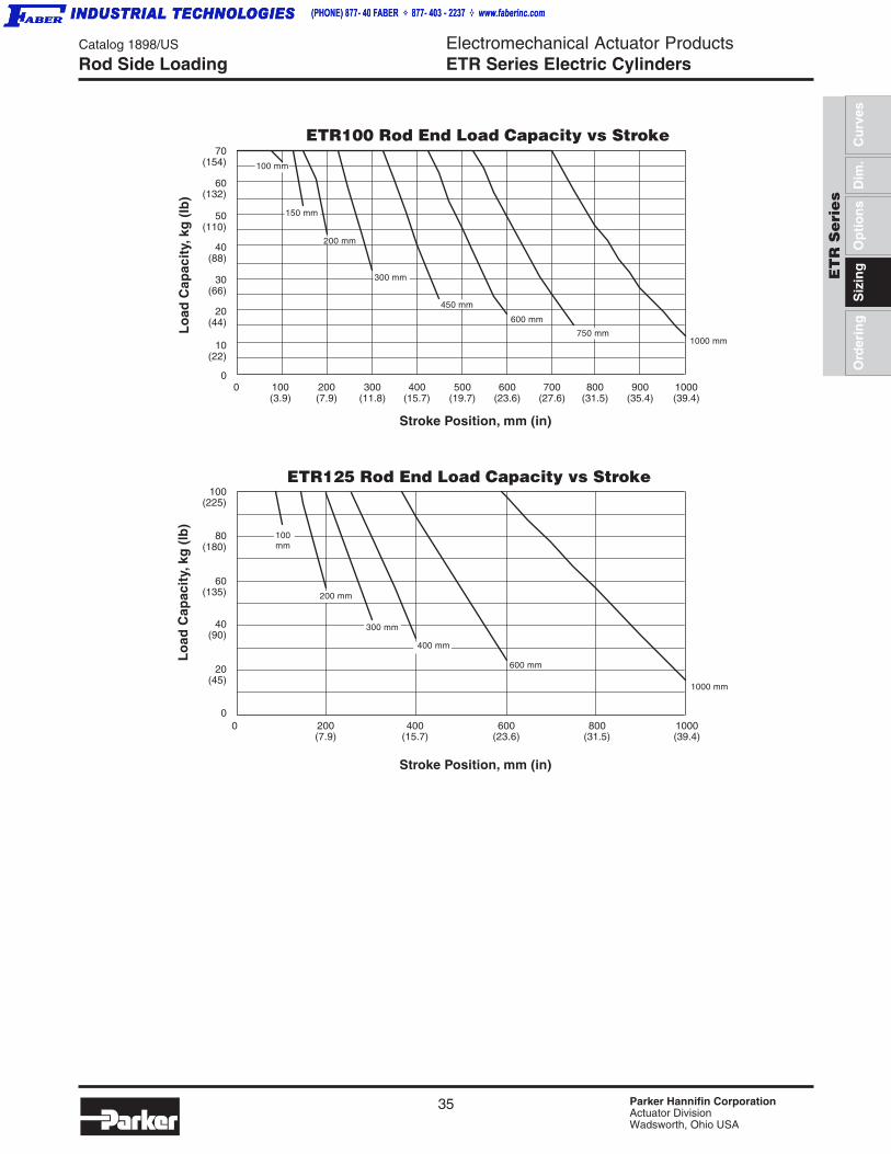
35 Parker Hannifin CorporationActuator DivisionWadsworth, Ohio USA
Catalog 1898/US
EngElectromechanical Actuator ProductsETR Series Electric Cylinders
ET
R S
eri
es
Cu
rves
Siz
ing
Dim
.O
rder
ing
Op
tio
ns
Rod Side Loading
200(7.9)
400(15.7)
600(23.6)
800(31.5)
1000(39.4)
Stroke Position, mm (in)
0
100(225)
80(180)
60(135)
20(45)
40(90)
0
Lo
ad C
apac
ity,
kg
(lb
)
ETR125 Rod End Load Capacity vs Stroke
100mm
200 mm
300 mm
400 mm
600 mm
1000 mm
100(3.9)
200(7.9)
300(11.8)
400(15.7)
500(19.7)
600(23.6)
700(27.6)
800(31.5)
900(35.4)
1000(39.4)
0
Stroke Position, mm (in)
70(154)
60(132)
40(88)
30(66)
10(22)
20(44)
0
ETR100 Rod End Load Capacity vs Stroke
50(110)
100 mm
150 mm
200 mm
300 mm
450 mm
600 mm
750 mm1000 mm
Lo
ad C
apac
ity,
kg
(lb
)
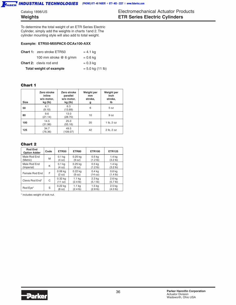
36 Parker Hannifin CorporationActuator DivisionWadsworth, Ohio USA
Catalog 1898/US
EngElectromechanical Actuator ProductsETR Series Electric Cylinders
Zero stroke Zero stroke Weight per Weight perinline parallel mm inch
w/o motor, w/o motor, stroke, stroke,Size kg (lb) kg (lb) g lb
504.1 6.3
6 5 oz(9.10) (13.89)
80 9.6 13.0 10 9 oz(21.14) (28.70)
100 14.5 25.020 1 lb, 2 oz
(31.96) (55.16)
125 34.7 49.5 42 2 lb, 2 oz(76.36) (109.07)
To determine the total weight of an ETR Series ElectricCylinder, simply add the weights in charts 1and 2. Thecylinder mounting style will also add to total weight.
Example: ETR50-M05PACX-DCAx100-AXX
Chart 1: zero stroke ETR50 = 4.1 kg
100 mm stroke @ 6 g/mm = 0.6 kg
Chart 2: clevis rod end = 0.3 kg
Total weight of example = 5.0 kg (11 lb)
Chart 1
Weights
Rod End Code ETR50 ETR80 ETR100 ETR125 Option Adder
Male Rod EndM
0.1 kg 0.25 kg 0.5 kg 1.4 kg(Metric) (4 oz) (9 oz) (1.2 lb) (3.2 lb)
Male Rod EndK
0.1 kg 0.25 kg 0.5 kg 1.4 kg(Imperial) (4 oz) (9 oz) (1.2 lb) (3.2 lb)
Female Rod End F0.06 kg 0.22 kg 0.4 kg 0.6 kg(2 oz) (9 oz) (14 oz) (1.4 lb)
Clevis Rod End* C0.32 kg 1.1 kg 2.3 kg 2.6 kg(11 oz) (2.4 lb) (5.1 lb) (5.7 lb)
Rod Eye* S0.22 kg 1.1 kg 1.5 kg 2.5 kg(8 oz) (2.4 lb) (2.8 lb) (4.0 lb)
Chart 2
* includes weight of lock nut.

37 Parker Hannifin CorporationActuator DivisionWadsworth, Ohio USA
Catalog 1898/US
EngElectromechanical Actuator ProductsETR Series Electric Cylinders
ET
R S
eri
es
Cu
rves
Siz
ing
Dim
.O
rder
ing
Op
tio
ns
13. Switches/Sensors:
_______ End of Travel ________ Home
14. Life Requirement _______________________
15. Lubrication:
_______ Grease (std) _______ Oil (option)
Application Requirements:
1. Stroke Length
2. Mounting:
Horizontal Vertical
Angle Degrees
3. Thrust Force
4. Load Weight
5. Speed
Maximum Minimum
6. Cycle Time
7. Duty Cycle
[time moving / total cycle time] x 100%
8. Repeatability Requirements
9. Accuracy Requirements
10. Is Load Externally Guided? _____________
If 'Yes', then how?________________________
11. Number of Stops Per Cycle
12. Max. Rod Side Load
at what stroke? ______________
Please provide as much information as possible.
SKETCH:
Application Fax
Name ____________________________________
Company _________________________________
Address __________________________________
Phone _______________ Fax _________________
e-mail ____________________________________
Cylinder Requirements:
1. Rod End _____________________________
2. Mounting Style _________________________
3. Options ______________________________
Contact Information:
For assistance, call 330-336-3511. When complete, fax to 330-334-3335.
Environmental Requirements:
1. Operating Temperature
Minimum __________ Maximum __________
2. Contamination
a. Particles____________________________
Type ______________________________
b. Liquid _____________________________
Type ______________________________
Special Considerations: _____________________
___________________________________________
___________________________________________

38 Parker Hannifin CorporationActuator DivisionWadsworth, Ohio USA
Electromechanical Actuator ProductsETR Series Electric Cylinders
Catalog 1898/US
Ordering Information
The cylinder body can be rotated in 90°incrememts. The side loading capacity of thecylinder will remain unchanged for the differentbody orientations.
Parallel Motor MountingParallel motor mounting position will be in standard position(P) shown relative to the cylinder mounting. Contact theApplication Department for special motor orientations (X).
Orientations
THRUST BEARINGLUBRICATION PORT
INTERNAL LUBRICATION PLUG
C
B
Std
A
As viewed from rod end of the actuator
Body Orientation OptionOptions allow switch groove and lubrication port to be accessible.

39 Parker Hannifin CorporationActuator DivisionWadsworth, Ohio USA
Catalog 1898/US
Brushless Servo SystemsElectromechanical Actuator ProductsETR Series Electric Cylinders
ET
R S
eri
es
Cu
rves
Siz
ing
Dim
.O
rder
ing
Op
tio
ns
Procedure for Customer Supplied MotorsCustomers who would like to have a customer supplied motor considered for mounting on an ETR Series actuator must followthese instructions:
1) Determine motor and ETR Series actuator desired for application. If the motor is not a standard Actuator Division offering,then contact the Applications Department with the following information:
a) Fax a clear drawing showing all pertinent motor dimensions and mounting details, (flange size, bolt hole pattern, motorshaft diameter and length, key dimensions if applicable, etc.) See diagram below.
b) Fax a summary of the motor performance. (i.e. torque curves, motor shaft radial load capability, etc.)
c) Approval of a motor by the Application Department means only that the motor can be physically mounted to thedesired ETR Series. Application success and performance based upon motor sizing or technology is the responsibilityof the customer.
2) Delivery is based upon customer supplied motor arrival at Actuator Division. ALL MOTORS MUST BE MOUNTED ATACTUATOR DIVISION TO MAINTAIN WARRANTY.
3) Final delivery will be established based upon customer’s (Distributor/ATC) estimate of motor’s arrival at Actuator Division.
IMPORTANT!! ALL CUSTOMER SUPPLIED MOTORS MUST BE MOUNTED AT ACTUATOR DIVISION. The customer shoulduse the purchase order number placed with Actuator Division as a mark number for the customer supplied motors shipped toActuator Division.
Parker Hannifin CorporationActuator Division135 Quadral DriveWadsworth, OH 44281Mark #: P. O. XXXXXX
Customer Supplied Motors
Company:Name:Address:
Phone:Fax:
Cylinder Model:Motor Manufacturer:Motor Model Number:
Fax to: Parker Hannifin CorporationActuator DivisionElectromechanical DepartmentFax: (330) 334-3335
4 x(CLEAR HOLE)
∅
OHLLOCATION
OHL FORCE
Please provide indicated dimensions.
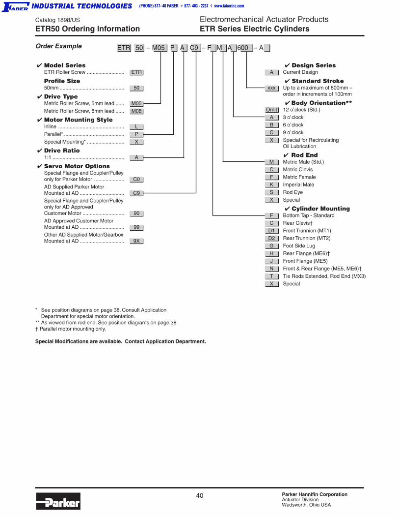
40 Parker Hannifin CorporationActuator DivisionWadsworth, Ohio USA
Electromechanical Actuator ProductsETR Series Electric Cylinders
Catalog 1898/US
Ordering Information
Order Example
ETR50 Ordering Information
Model SeriesETR Roller Screw .......................... ETR
Profile Size50mm ............................................. 50
Drive TypeMetric Roller Screw, 5mm lead ...... M05
Metric Roller Screw, 8mm lead ...... M08
Motor Mounting StyleInline .............................................. L
Parallel* .......................................... P
Special Mounting* .......................... X
Drive Ratio1:1 .................................................. A
Servo Motor OptionsSpecial Flange and Coupler/Pulleyonly for Parker Motor ..................... C0
AD Supplied Parker MotorMounted at AD ............................... C9Special Flange and Coupler/Pulleyonly for AD ApprovedCustomer Motor ............................. 90
AD Approved Customer MotorMounted at AD ............................... 99
Other AD Supplied Motor/GearboxMounted at AD ............................... 9X
Design SeriesA Current Design
Standard Strokexxx Up to a maximum of 800mm –
order in increments of 100mm
Body Orientation**Omit 12 o’clock (Std.)
A 3 o’clockB 6 o’clock
C 9 o’clock
X Special for RecirculatingOil Lubrication
Rod EndM Metric Male (Std.)
C Metric Clevis
F Metric FemaleK Imperial Male
S Rod Eye
X Special
Cylinder MountingF Bottom Tap - Standard
C Rear Clevis†
D1 Front Trunnion (MT1)D2 Rear Trunnion (MT2)
G Foot Side Lug
H Rear Flange (ME6)†J Front Flange (ME5)
N Front & Rear Flange (ME5, ME6)†
T Tie Rods Extended, Rod End (MX3)X Special
ETR 50 – M05 P A C9 – F M A 600 – A
* See position diagrams on page 38. Consult ApplicationDepartment for special motor orientation.
** As viewed from rod end. See position diagrams on page 38.† Parallel motor mounting only.
Special Modifications are available. Contact Application Department.
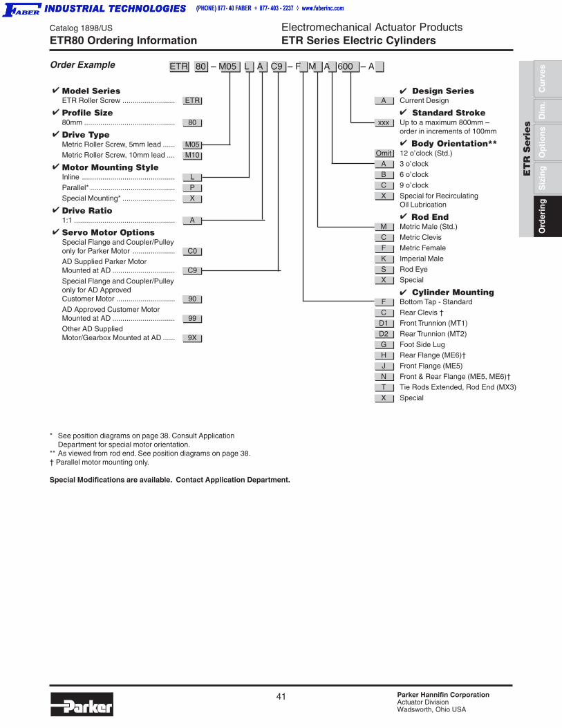
41 Parker Hannifin CorporationActuator DivisionWadsworth, Ohio USA
Catalog 1898/US
Brushless Servo SystemsElectromechanical Actuator ProductsETR Series Electric Cylinders
ET
R S
eri
es
Cu
rves
Siz
ing
Dim
.O
rder
ing
Op
tio
ns
ETR80 Ordering Information
Order Example
* See position diagrams on page 38. Consult ApplicationDepartment for special motor orientation.
** As viewed from rod end. See position diagrams on page 38.† Parallel motor mounting only.
Special Modifications are available. Contact Application Department.
Design SeriesA Current Design
Standard Strokexxx Up to a maximum 800mm –
order in increments of 100mm
Body Orientation**Omit 12 o’clock (Std.)
A 3 o’clock
B 6 o’clock
C 9 o’clockX Special for Recirculating
Oil Lubrication
Rod EndM Metric Male (Std.)
C Metric ClevisF Metric Female
K Imperial Male
S Rod EyeX Special
Cylinder MountingF Bottom Tap - Standard
C Rear Clevis †D1 Front Trunnion (MT1)
D2 Rear Trunnion (MT2)
G Foot Side LugH Rear Flange (ME6)†
J Front Flange (ME5)
N Front & Rear Flange (ME5, ME6)†T Tie Rods Extended, Rod End (MX3)
X Special
Model SeriesETR Roller Screw .......................... ETR
Profile Size80mm ............................................. 80
Drive TypeMetric Roller Screw, 5mm lead ...... M05Metric Roller Screw, 10mm lead .... M10
Motor Mounting StyleInline .............................................. L
Parallel* .......................................... PSpecial Mounting* .......................... X
Drive Ratio1:1 .................................................. A
Servo Motor OptionsSpecial Flange and Coupler/Pulleyonly for Parker Motor ..................... C0AD Supplied Parker MotorMounted at AD ............................... C9
Special Flange and Coupler/Pulleyonly for AD ApprovedCustomer Motor ............................. 90
AD Approved Customer MotorMounted at AD ............................... 99Other AD SuppliedMotor/Gearbox Mounted at AD ...... 9X
ETR 80 – M05 L A C9 – F M A 600 – A
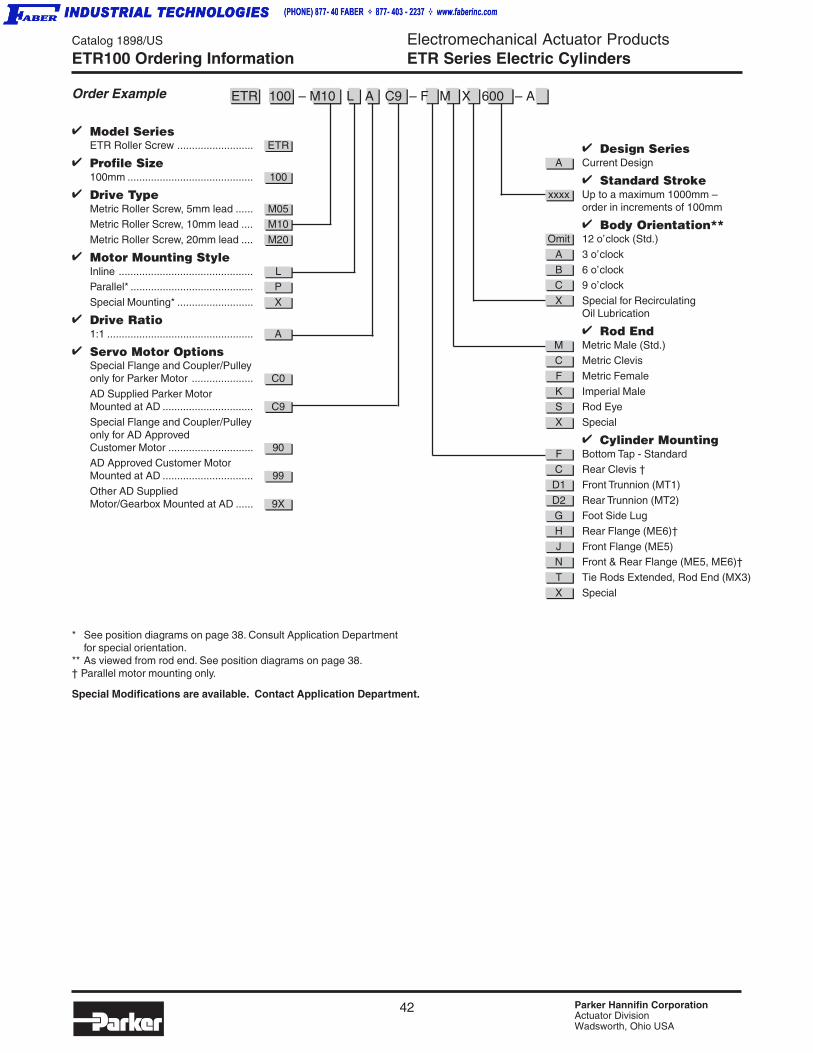
42 Parker Hannifin CorporationActuator DivisionWadsworth, Ohio USA
Electromechanical Actuator ProductsETR Series Electric Cylinders
Catalog 1898/US
Ordering Information
Order Example
ETR100 Ordering Information
* See position diagrams on page 38. Consult Application Departmentfor special orientation.
** As viewed from rod end. See position diagrams on page 38.† Parallel motor mounting only.
Special Modifications are available. Contact Application Department.
Design SeriesA Current Design
Standard Strokexxxx Up to a maximum 1000mm –
order in increments of 100mm
Body Orientation**Omit 12 o’clock (Std.)
A 3 o’clock
B 6 o’clockC 9 o’clock
X Special for RecirculatingOil Lubrication
Rod EndM Metric Male (Std.)C Metric Clevis
F Metric Female
K Imperial MaleS Rod Eye
X Special
Cylinder MountingF Bottom Tap - StandardC Rear Clevis †
D1 Front Trunnion (MT1)
D2 Rear Trunnion (MT2)G Foot Side Lug
H Rear Flange (ME6)†
J Front Flange (ME5)N Front & Rear Flange (ME5, ME6)†
T Tie Rods Extended, Rod End (MX3)
X Special
Model SeriesETR Roller Screw .......................... ETR
Profile Size100mm ........................................... 100
Drive TypeMetric Roller Screw, 5mm lead ...... M05Metric Roller Screw, 10mm lead .... M10
Metric Roller Screw, 20mm lead .... M20
Motor Mounting StyleInline .............................................. LParallel* .......................................... P
Special Mounting* .......................... X
Drive Ratio1:1 .................................................. A
Servo Motor OptionsSpecial Flange and Coupler/Pulleyonly for Parker Motor ..................... C0
AD Supplied Parker MotorMounted at AD ............................... C9
Special Flange and Coupler/Pulleyonly for AD ApprovedCustomer Motor ............................. 90AD Approved Customer MotorMounted at AD ............................... 99
Other AD SuppliedMotor/Gearbox Mounted at AD ...... 9X
ETR 100 – M10 L A C9 – F M X 600 – A

43 Parker Hannifin CorporationActuator DivisionWadsworth, Ohio USA
Catalog 1898/US
Brushless Servo SystemsElectromechanical Actuator ProductsETR Series Electric Cylinders
ET
R S
eri
es
Cu
rves
Siz
ing
Dim
.O
rder
ing
Op
tio
ns
Order Example
ETR125 Ordering Information
Design SeriesA Current Design
Strokexxxx Up to a maximum 1000 mm –
order in increments of 100mm
Body Orientation**Omit 12 o’clock (Std.)
A 3 o’clock
B 6 o’clock
C 9 o’clockX Special for Recirculating
Oil Lubrication
Rod EndM Metric Male (Std.)
C Metric ClevisF Metric Female
K Imperial Male
S Rod EyeX Special
Cylinder MountingF Bottom Tap - Standard
C Rear Clevis †D1 Front Trunnion (MT1)
D2 Rear Trunnion (MT2)
G Foot Side LugH Rear Flange (ME6)†
J Front Flange (ME5)
N Front & Rear Flange (ME5, ME6)†T Tie Rods Extended, Rod End (MX3)
X Special
Model SeriesETR Roller Screw .......................... ETR
Profile Size125mm ........................................... 125
Drive TypeMetric Roller Screw, 5mm lead ...... M05Metric Roller Screw, 10mm lead .... M10
Metric Roller Screw, 20mm lead .... M20
Motor Mounting StyleInline .............................................. LParallel* .......................................... P
Special Mounting* .......................... X
Drive Ratio1:1 .................................................. A
Servo MotorSpecial Flange and Coupler/Pulleyonly for Parker Motor ..................... C0
AD Supplied Parker MotorMounted at AD ............................... C9
Special Flange and Coupler/Pulleyonly for AD ApprovedCustomer Motor ............................. 90AD Approved Customer MotorMounted at AD ............................... 99
Other AD SuppliedMotor/Gearbox Mounted at AD ...... 9X
ETR 125 – M10 P A C9 – F M X 800 – A
* See position diagrams on page 38. Consult Application Departmentfor special orientation.
** As viewed from rod end. See position diagrams on page 38.† Parallel motor mounting only.
Special Modifications are available. Contact Application Department.

44 Parker Hannifin CorporationActuator DivisionWadsworth, Ohio USA
Electromechanical Actuator ProductsETR Series Electric Cylinders
Catalog 1898/US
Ordering InformationNotes
45 Parker Hannifin CorporationActuator DivisionWadsworth, Ohio USA
Catalog 1898/US Electromechanical Actuator ProductsDrives, Motors & Gearheads
Dri
ves,
Mo
tors
, G
ea
rhe
ad
s
Dri
ves
Gea
rhea
ds
Mo
tors
Contents
Servo Drives & ControllersCompax3 ........................................................... 46HPD ................................................................... 55
Servo MotorsBE Series ........................................................... 59NeoMetric & J Series ......................................... 62SMN Series ........................................................ 67M Series ............................................................. 69MaxPlus Series .................................................. 71
Servo Motor DimensionsBE Series ........................................................... 73NeoMetric and J Series ...................................... 74SMN Series ........................................................ 75M Series ............................................................. 76MaxPlus Series .................................................. 77
Precision GearheadsGTN, GTR .......................................................... 81PTN, PTR .......................................................... 82

46 Parker Hannifin CorporationActuator DivisionWadsworth, Ohio USA
Catalog 1898/US Electromechanical Actuator ProductsDrives, Motors & Gearheads
Compact, Intelligent and PowerfulIndustrial Servo Drives &Drive/ControllersWith its high-performance and modular design, theCompax3 family of industrial servo drives and drive/controllers offers a new level of servo performance andflexibility. The modular structure of the Compax3 familyallows options such as intelligent motion controllers,fieldbus interfaces and industry standard motor feedback. Inaddition, numerous expansion options can be added to thestandard product in order to optimize the capabilitiesrequired for today’s demanding servo applications.
Compax3 Series
Compax3 Features• Available in both 120/240 VAC and 480 VAC input versions
• Current output from 2.5 A (rms) continuous to 30 A (rms)continuous
• Resolver, encoder or high-resolution SinCos® Absoluterotary encoder feedback (single- or multi-turn)
• Internal regeneration circuitry; external resistor connectionsfor additional power dissipation
• Easy-to-use wizards-based configuration and programmingvia C3 ServoManager™ software package
• Full diagnostic, tuning and 4-channel oscilloscope toolsprovided in the standard C3 ServoManager™ software
• CE (EMC & LVD), UL, cUL approval
T10 Features• Base servo drive
• ±10 V analog
• Step and direction
• Torque/velocity control
• Position control
• Encoder tracking
T11 Features• Base indexer drive
• Up to 31 stored profiles
• Profile select via digtialinputs
• Multi-profile sequences
• Profibus
• CANopen
T30 Features• Full-featured
programmable drive/controller
• IEC61131-3 programmingflexibility
• PLCopen, Parker motionfunction blocks
• Complex motion
• Profibus
• CANopen
T40 Features• T30 programming
capability
• Electronic cam control
• Electronic gearing
• Position capture
• Profibus
• CANopen
• HEDA
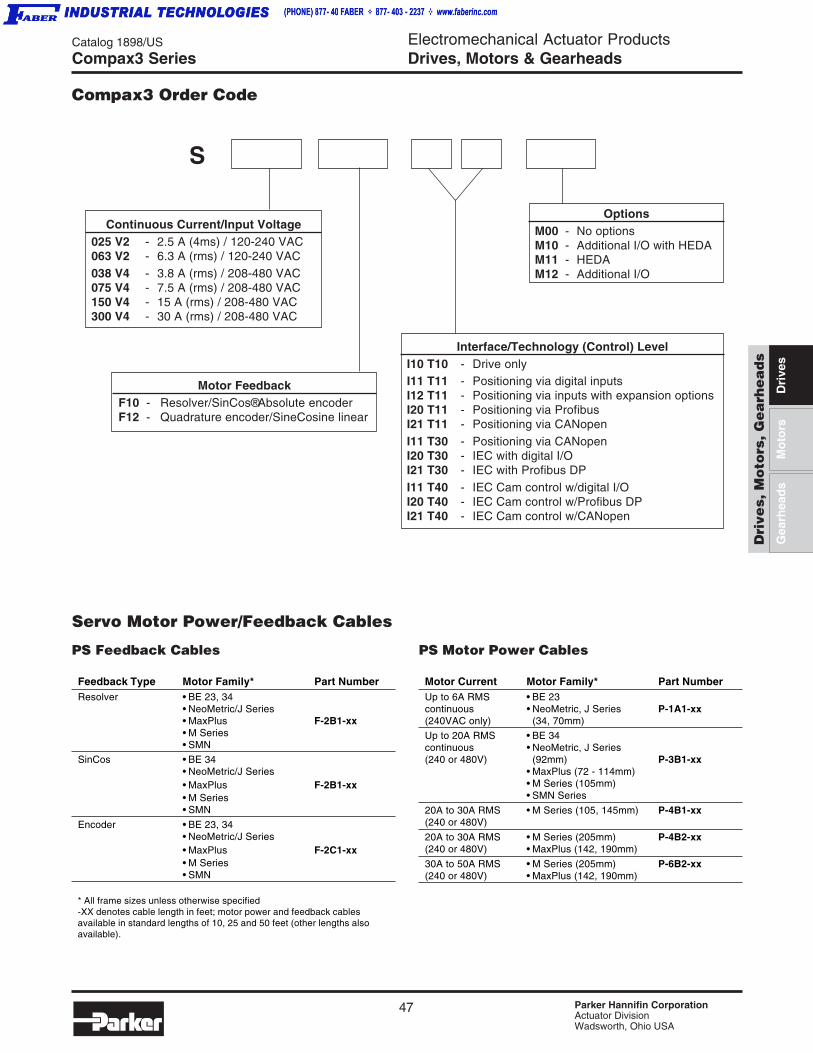
47 Parker Hannifin CorporationActuator DivisionWadsworth, Ohio USA
Catalog 1898/US Electromechanical Actuator ProductsDrives, Motors & Gearheads
Dri
ves,
Mo
tors
, G
ea
rhe
ad
s
Dri
ves
Gea
rhea
ds
Mo
tors
Compax3 Series
Compax3 Order Code
Continuous Current/Input Voltage025 V2 - 2.5 A (4ms) / 120-240 VAC063 V2 - 6.3 A (rms) / 120-240 VAC038 V4 - 3.8 A (rms) / 208-480 VAC075 V4 - 7.5 A (rms) / 208-480 VAC150 V4 - 15 A (rms) / 208-480 VAC300 V4 - 30 A (rms) / 208-480 VAC
Motor FeedbackF10 - Resolver/SinCos® Absolute encoderF12 - Quadrature encoder/SineCosine linear
Interface/Technology (Control) LevelI10 T10 - Drive onlyI11 T11 - Positioning via digital inputsI12 T11 - Positioning via inputs with expansion optionsI20 T11 - Positioning via ProfibusI21 T11 - Positioning via CANopenI11 T30 - Positioning via CANopenI20 T30 - IEC with digital I/OI21 T30 - IEC with Profibus DPI11 T40 - IEC Cam control w/digital I/OI20 T40 - IEC Cam control w/Profibus DPI21 T40 - IEC Cam control w/CANopen
OptionsM00 - No optionsM10 - Additional I/O with HEDAM11 - HEDAM12 - Additional I/O
S
PS Feedback Cables
Feedback Type Motor Family* Part NumberResolver • BE 23, 34
• NeoMetric/J Series• MaxPlus F-2B1-xx• M Series• SMN
SinCos • BE 34• NeoMetric/J Series• MaxPlus F-2B1-xx• M Series• SMN
Encoder • BE 23, 34• NeoMetric/J Series• MaxPlus F-2C1-xx• M Series• SMN
* All frame sizes unless otherwise specified-XX denotes cable length in feet; motor power and feedback cablesavailable in standard lengths of 10, 25 and 50 feet (other lengths alsoavailable).
Servo Motor Power/Feedback Cables
PS Motor Power Cables
Motor Current Motor Family* Part NumberUp to 6A RMS • BE 23continuous • NeoMetric, J Series P-1A1-xx(240VAC only) (34, 70mm)
Up to 20A RMS • BE 34continuous • NeoMetric, J Series(240 or 480V) (92mm) P-3B1-xx
• MaxPlus (72 - 114mm)• M Series (105mm)• SMN Series
20A to 30A RMS • M Series (105, 145mm) P-4B1-xx(240 or 480V)
20A to 30A RMS • M Series (205mm) P-4B2-xx(240 or 480V) • MaxPlus (142, 190mm)
30A to 50A RMS • M Series (205mm) P-6B2-xx(240 or 480V) • MaxPlus (142, 190mm)
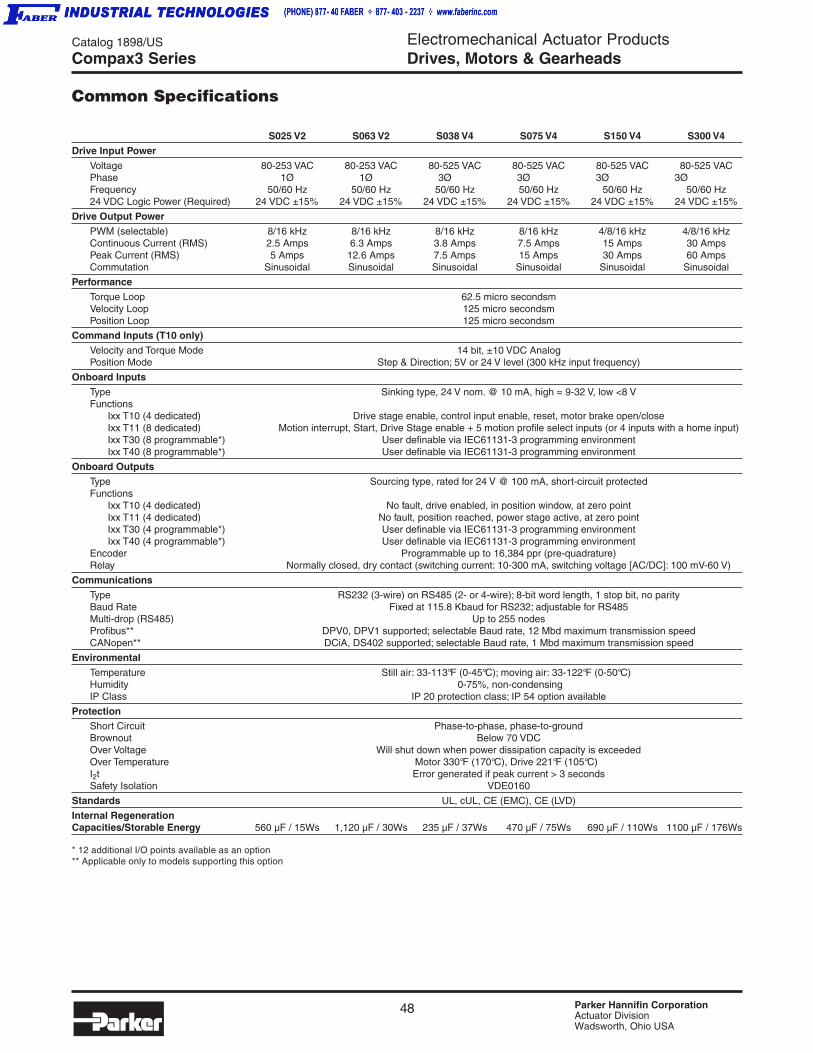
48 Parker Hannifin CorporationActuator DivisionWadsworth, Ohio USA
Catalog 1898/US Electromechanical Actuator ProductsDrives, Motors & Gearheads
S025 V2 S063 V2 S038 V4 S075 V4 S150 V4 S300 V4
Drive Input Power
Voltage 80-253 VAC 80-253 VAC 80-525 VAC 80-525 VAC 80-525 VAC 80-525 VACPhase 1Ø 1Ø 3Ø 3Ø 3Ø 3ØFrequency 50/60 Hz 50/60 Hz 50/60 Hz 50/60 Hz 50/60 Hz 50/60 Hz24 VDC Logic Power (Required) 24 VDC ±15% 24 VDC ±15% 24 VDC ±15% 24 VDC ±15% 24 VDC ±15% 24 VDC ±15%
Drive Output Power
PWM (selectable) 8/16 kHz 8/16 kHz 8/16 kHz 8/16 kHz 4/8/16 kHz 4/8/16 kHzContinuous Current (RMS) 2.5 Amps 6.3 Amps 3.8 Amps 7.5 Amps 15 Amps 30 AmpsPeak Current (RMS) 5 Amps 12.6 Amps 7.5 Amps 15 Amps 30 Amps 60 AmpsCommutation Sinusoidal Sinusoidal Sinusoidal Sinusoidal Sinusoidal Sinusoidal
Performance
Torque Loop 62.5 micro secondsmVelocity Loop 125 micro secondsmPosition Loop 125 micro secondsm
Command Inputs (T10 only)
Velocity and Torque Mode 14 bit, ±10 VDC AnalogPosition Mode Step & Direction; 5V or 24 V level (300 kHz input frequency)
Onboard Inputs
Type Sinking type, 24 V nom. @ 10 mA, high = 9-32 V, low <8 VFunctions
Ixx T10 (4 dedicated) Drive stage enable, control input enable, reset, motor brake open/closeIxx T11 (8 dedicated) Motion interrupt, Start, Drive Stage enable + 5 motion profile select inputs (or 4 inputs with a home input)Ixx T30 (8 programmable*) User definable via IEC61131-3 programming environmentIxx T40 (8 programmable*) User definable via IEC61131-3 programming environment
Onboard Outputs
Type Sourcing type, rated for 24 V @ 100 mA, short-circuit protectedFunctions
Ixx T10 (4 dedicated) No fault, drive enabled, in position window, at zero pointIxx T11 (4 dedicated) No fault, position reached, power stage active, at zero pointIxx T30 (4 programmable*) User definable via IEC61131-3 programming environmentIxx T40 (4 programmable*) User definable via IEC61131-3 programming environment
Encoder Programmable up to 16,384 ppr (pre-quadrature)Relay Normally closed, dry contact (switching current: 10-300 mA, switching voltage [AC/DC]: 100 mV-60 V)
Communications
Type RS232 (3-wire) on RS485 (2- or 4-wire); 8-bit word length, 1 stop bit, no parityBaud Rate Fixed at 115.8 Kbaud for RS232; adjustable for RS485Multi-drop (RS485) Up to 255 nodesProfibus** DPV0, DPV1 supported; selectable Baud rate, 12 Mbd maximum transmission speedCANopen** DCiA, DS402 supported; selectable Baud rate, 1 Mbd maximum transmission speed
Environmental
Temperature Still air: 33-113°F (0-45°C); moving air: 33-122°F (0-50°C)Humidity 0-75%, non-condensingIP Class IP 20 protection class; IP 54 option available
ProtectionShort Circuit Phase-to-phase, phase-to-groundBrownout Below 70 VDCOver Voltage Will shut down when power dissipation capacity is exceededOver Temperature Motor 330°F (170°C), Drive 221°F (105°C)I2t Error generated if peak current > 3 secondsSafety Isolation VDE0160
Standards UL, cUL, CE (EMC), CE (LVD)
Internal RegenerationCapacities/Storable Energy 560 µF / 15Ws 1,120 µF / 30Ws 235 µF / 37Ws 470 µF / 75Ws 690 µF / 110Ws 1100 µF / 176Ws
* 12 additional I/O points available as an option** Applicable only to models supporting this option
Common Specifications
Compax3 Series
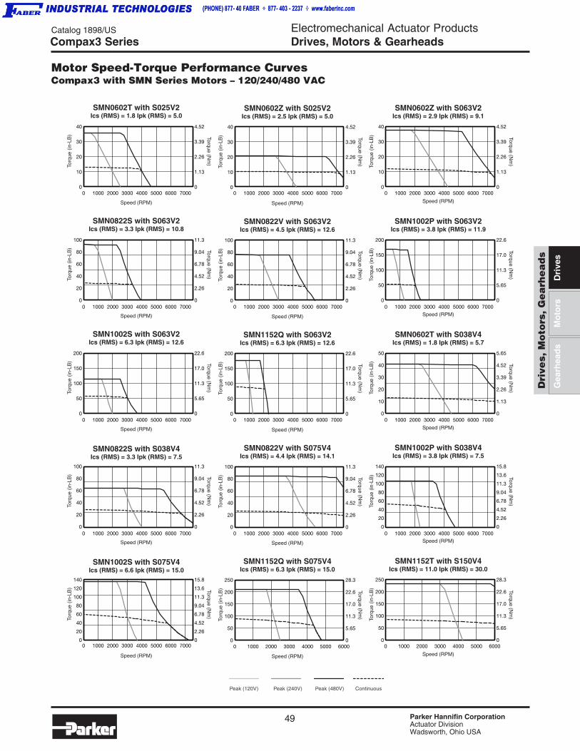
49 Parker Hannifin CorporationActuator DivisionWadsworth, Ohio USA
Catalog 1898/US Electromechanical Actuator ProductsDrives, Motors & Gearheads
Dri
ves,
Mo
tors
, G
ea
rhe
ad
s
Dri
ves
Gea
rhea
ds
Mo
tors
Motor Speed-Torque Performance CurvesCompax3 with SMN Series Motors – 120/240/480 VAC
Compax3 Series
0 1000 2000 3000 4000 5000 6000 7000 0 1000 2000 3000 4000 5000 6000 7000 0 1000 2000 3000 4000 5000 6000 7000
0 1000 2000 3000 4000 5000 6000 7000 0 1000 2000 3000 4000 5000 6000 7000 0 1000 2000 3000 4000 5000 6000 7000
0 1000 2000 3000 4000 5000 6000 7000 0 1000 2000 3000 4000 5000 6000 7000 0 1000 2000 3000 4000 5000 6000 7000
0 1000 2000 3000 4000 5000 6000 7000
0 1000 2000 3000 4000 5000 6000 7000
0 1000 2000 3000 4000 5000 6000 7000 0 1000 2000 3000 4000 5000 6000 7000
0
10
20
30
40
0
1.13
2.26
3.39
4.52
0
1.13
2.26
3.39
4.52
0
1.13
2.26
3.39
4.52
SMN0602T with S025V2Ics (RMS) = 1.8 Ipk (RMS) = 5.0
Speed (RPM)
Torq
ue (
in-L
B) Torque (N
m)
0
10
20
30
40
SMN0602Z with S025V2Ics (RMS) = 2.5 Ipk (RMS) = 5.0
Speed (RPM)
Torq
ue (
in-L
B) Torque (N
m)
0
10
20
30
40
SMN0602Z with S063V2Ics (RMS) = 2.9 Ipk (RMS) = 9.1
Torq
ue (
in-L
B) Torque (N
m)
Speed (RPM)
0
20
40
60
80
100
0
2.26
4.52
6.78
9.04
11.3
0
2.26
4.52
6.78
9.04
11.3
0
2.26
4.52
6.78
9.04
11.3
0
2.26
4.52
6.78
9.04
11.3
SMN0822S with S063V2Ics (RMS) = 3.3 Ipk (RMS) = 10.8
Speed (RPM)
Torq
ue (
in-L
B) Torque (N
m)
0
20
40
60
80
100
SMN0822V with S063V2Ics (RMS) = 4.5 Ipk (RMS) = 12.6
Speed (RPM)
Torq
ue (
in-L
B) Torque (N
m)
0
50
100
150
200
0
5.65
11.3
17.0
22.6
0
5.65
11.3
17.0
22.6
0
5.65
11.3
17.0
22.6
SMN1002P with S063V2Ics (RMS) = 3.8 Ipk (RMS) = 11.9
Torq
ue (
in-L
B) Torque (N
m)
Speed (RPM)
0
50
100
150
200
SMN1002S with S063V2Ics (RMS) = 6.3 Ipk (RMS) = 12.6
Speed (RPM)
Torq
ue (
in-L
B) Torque (N
m)
0
50
100
150
200
SMN1152Q with S063V2Ics (RMS) = 6.3 Ipk (RMS) = 12.6
Speed (RPM)
Torq
ue (
in-L
B) Torque (Nm
)
0
10
20
30
40
50
0
1.13
2.26
3.39
4.52
5.65
SMN0602T with S038V4Ics (RMS) = 1.8 Ipk (RMS) = 5.7
Torq
ue (
in-L
B) Torque (Nm
)
Speed (RPM)
0
20
40
60
80
100
Speed (RPM)
Torq
ue (
in-L
B) Torque (N
m)
0
20
40
60
80
100
SMN0822V with S075V4Ics (RMS) = 4.4 Ipk (RMS) = 14.1
Speed (RPM)
Torq
ue (
in-L
B) Torque (N
m)
0
20
40
60
80
100
120
140
0
2.26
4.52
6.78
9.04
11.3
13.6
15.8
0
2.26
4.52
6.78
9.04
11.3
13.6
15.8
SMN1002P with S038V4Ics (RMS) = 3.8 Ipk (RMS) = 7.5
Torq
ue (
in-L
B) Torque (N
m)
Speed (RPM)
0
20
40
60
80
100
120
140
Speed (RPM)
Torq
ue (
in-L
B) Torque (N
m)
0 1000 2000 3000 4000 5000 60000
50
100
150
200
250
0
5.65
11.3
17.0
22.6
28.3
0
5.65
11.3
17.0
22.6
28.3
SMN1152Q with S075V4Ics (RMS) = 6.3 Ipk (RMS) = 15.0
Speed (RPM)
Torq
ue (
in-L
B) Torque (N
m)
0 1000 2000 3000 4000 5000 60000
50
100
150
200
250
SMN1152T with S150V4Ics (RMS) = 11.0 Ipk (RMS) = 30.0
Torq
ue (
in-L
B) Torque (N
m)
Speed (RPM)
Peak (480V)Peak (120V) Peak (240V) Continuous
SMN0822S with S038V4Ics (RMS) = 3.3 Ipk (RMS) = 7.5
SMN1002S with S075V4Ics (RMS) = 6.6 Ipk (RMS) = 15.0
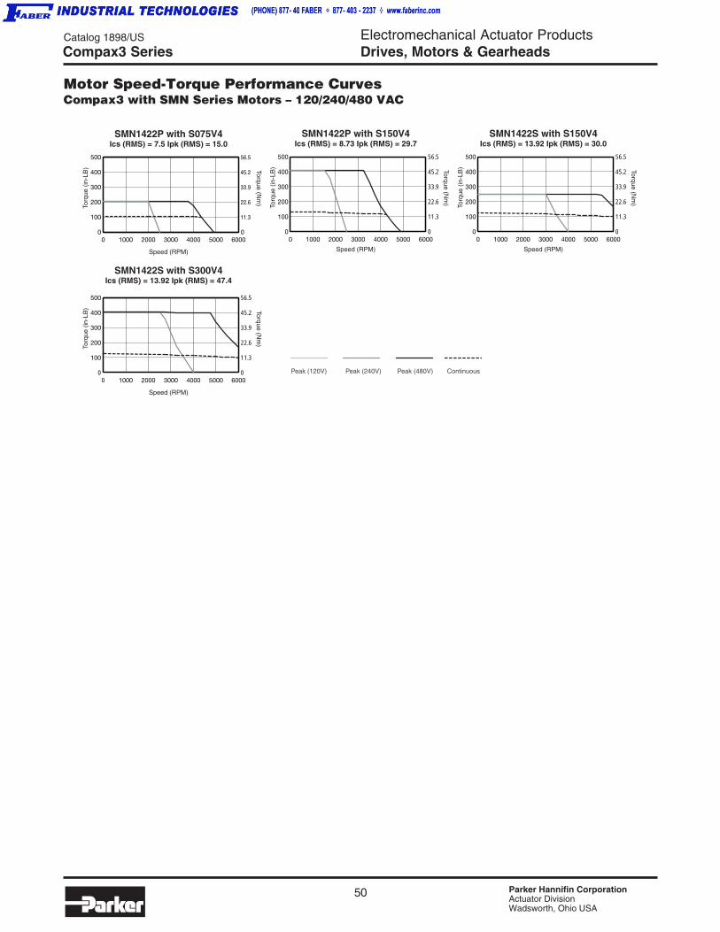
50 Parker Hannifin CorporationActuator DivisionWadsworth, Ohio USA
Catalog 1898/US Electromechanical Actuator ProductsDrives, Motors & Gearheads
0 1000 2000 3000 4000 5000 60000
100
200
300
400
500
0
11.3
22.6
33.9
45.2
56.5
0
11.3
22.6
33.9
45.2
56.5
0
11.3
22.6
33.9
45.2
56.5
0
11.3
22.6
33.9
45.2
56.5
SMN1422P with S075V4Ics (RMS) = 7.5 Ipk (RMS) = 15.0
Speed (RPM)
Torq
ue (
in-L
B) Torque (N
m)
0 1000 2000 3000 4000 5000 60000
100
200
300
400
500
SMN1422P with S150V4Ics (RMS) = 8.73 Ipk (RMS) = 29.7
Torq
ue (
in-L
B) Torque (N
m)
Speed (RPM)
0 1000 2000 3000 4000 5000 60000
100
200
300
400
500
SMN1422S with S150V4Ics (RMS) = 13.92 Ipk (RMS) = 30.0
Torq
ue (
in-L
B) Torque (N
m)
Speed (RPM)
0 1000 2000 3000 4000 5000 60000
100
200
300
400
500
SMN1422S with S300V4Ics (RMS) = 13.92 Ipk (RMS) = 47.4
Speed (RPM)
Torq
ue (
in-L
B) Torque (N
m)
Peak (480V)Peak (120V) Peak (240V) Continuous
Motor Speed-Torque Performance CurvesCompax3 with SMN Series Motors – 120/240/480 VAC
Compax3 Series

51 Parker Hannifin CorporationActuator DivisionWadsworth, Ohio USA
Catalog 1898/US Electromechanical Actuator ProductsDrives, Motors & Gearheads
Dri
ves,
Mo
tors
, G
ea
rhe
ad
s
Dri
ves
Gea
rhea
ds
Mo
tors
Motor Speed-Torque Performance CurvesCompax3 with BE Motors – 23 and 34 frame, 120/240 VAC
Compax3 Series
0 1000 2000 3000 4000 50000
30
60
90
120
150
0
.21
.42
.63
.84
1.05
0 1000 2000 3000 4000 50000
50
100
150
200
250
300
0
.35
.70
1.05
1.40
1.75
2.10
0 1000 2000 3000 4000 50000
100
200
300
400
500
0
.70
1.40
2.10
2.80
3.50
0 1000 2000 3000 4000 50000
100
200
300
400
500
600
700
0
.70
1.40
2.10
2.80
3.50
4.20
4.90
0 1000 2000 3000 4000 50000
10
20
30
40
50
60
0
1.12
2.24
3.36
4.48
5.60
6.73
0 1000 2000 3000 4000 50000
10
20
30
40
50
60
70
80
0
1.12
2.24
3.36
4.48
5.60
6.73
7.85
8.97
0
1.12
2.24
3.36
4.48
5.60
6.72
7.85
8.97
0 1000 2000 3000 4000 50000
10
20
30
40
50
60
70
80
0 1000 2000 3000 4000 50000
20
40
60
80
100
0
2.24
4.48
6.72
8.97
11.2
BE230DR with S025 V2Ics (RMS) = 2.39, Ipk (RMS) = 7.2
Speed (RPM)
Torq
ue (
oz-in
) Torque (Nm
)
BE231DR with S025 V2Ics (RMS) = 2.1, Ipk (RMS) = 6.3
Speed (RPM)To
rque
(oz
-in) Torque (N
m)
BE232DR with S025 V2Ics (RMS) = 2.14, Ipk (RMS) = 6.4
Speed (RPM)
Torq
ue (
oz-in
) Torque (Nm
)
BE233DR with S025 V2Ics (RMS) = 1.9, Ipk (RMS) = 5.7
Speed (RPM)
Torq
ue (
oz-in
) Torque (Nm
)
BE341FR with S063 V2Ics (RMS) = 3.93, Ipk (RMS) = 11.8
Speed (RPM)
Torq
ue (
Lb-in
) Torque (Nm
)
BE342HR with S063 V2Ics (RMS) = 5.23, Ipk (RMS) = 15.7
Speed (RPM)
Torq
ue (
Lb-in
) Torque (Nm
)
BE343JR with S063 V2Ics (RMS) = 7.59, Ipk (RMS) = 22.8
Speed (RPM)
Torq
ue (
Lb-in
) Torque (Nm
)
BE344JR with S063 V2Ics (RMS) = 6.92, Ipk (RMS) = 20.7
Speed (RPM)
Torq
ue (
Lb-in
) Torque (Nm
)
CONTINUOUS PEAK
120 VAC
CONTINUOUS PEAK
240 VAC

52 Parker Hannifin CorporationActuator DivisionWadsworth, Ohio USA
Catalog 1898/US Electromechanical Actuator ProductsDrives, Motors & Gearheads
Motor Speed-Torque Performance CurvesCompax3 with NeoMetric and J Series Motors – NEMA 34/70mm and 92mm frame
Compax3 Series
0 1500 3000 4500 6000 75000
10
20
30
40
50
0
1.12
2.24
3.36
4.48
5.60
0 1500 3000 4500 6000 75000
10
20
30
40
50
0
1.12
2.24
3.36
4.48
5.60
0 1500 3000 4500 6000 75000
10
20
30
40
50
0
1.12
2.24
3.36
4.48
5.60
0 1500 3000 4500 6000 75000
10
20
30
40
50
0
1.12
2.24
3.36
4.48
5.60
0 1500 3000 4500 6000 75000
10
20
30
40
50
60
0
1.12
2.24
3.36
4.48
5.60
6.73
0 1000 2000 3000 4000 5000 60000
10
20
30
40
50
60
70
80
0
1.12
2.24
3.36
4.48
5.60
6.73
7.85
8.97
0 1000 2000 3000 4000 50000
20
40
60
80
100
0
2.24
4.48
6.73
8.97
11.2
N0702FR with S063 V2Ics (RMS) = 4.2 Ipk (RMS) = 12.6
Speed (RPM)To
rque
(Lb
-in) Torque (N
m)
N0703GR with S063 V2Ics (RMS) = 5.8 Ipk (RMS) = 12.6
Speed (RPM)
Torq
ue (
Lb-in
) Torque (Nm
)
N0704GR with S063 V2Ics (RMS) = 5.9 Ipk (RMS) = 12.6
Speed (RPM)
Torq
ue (
Lb-in
) Torque (Nm
)
N0921GR with S063 V2Ics (RMS) = 5.2 Ipk (RMS) = 12.6
Speed (RPM)
Torq
ue (
Lb-in
) Torque (Nm
)
N0922JR with S063 V2Ics (RMS) = 6.3 Ipk (RMS) = 12.6
Speed (RPM)
Torq
ue (
Lb-in
) Torque (Nm
)
N0923HR with S063 V2Ics (RMS) = 6.3 Ipk (RMS) = 12.6
Speed (RPM)
Torq
ue (
Lb-in
) Torque (Nm
)
N0924JR with S063 V2Ics (RMS) = 6.3 Ipk (RMS) = 12.6
Speed (RPM)
Torq
ue (
Lb-in
) Torque (Nm
)
CONTINUOUS PEAK
120 VAC
CONTINUOUS PEAK
240 VAC
0 1500 3000 4500 6000 75000
5
10
15
20
0
.56
1.12
1.68
2.24
N0701FR with S063 V2Ics (RMS) = 4.1 Ipk (RMS) = 12.4
Speed (RPM)
Torq
ue (
Lb-in
) Torque (Nm
)
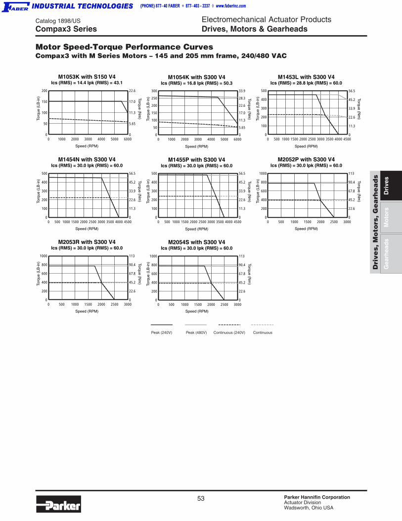
53 Parker Hannifin CorporationActuator DivisionWadsworth, Ohio USA
Catalog 1898/US Electromechanical Actuator ProductsDrives, Motors & Gearheads
Dri
ves,
Mo
tors
, G
ea
rhe
ad
s
Dri
ves
Gea
rhea
ds
Mo
tors
Motor Speed-Torque Performance CurvesCompax3 with M Series Motors – 145 and 205 mm frame, 240/480 VAC
Compax3 Series
0 1000 2000 3000 4000 5000 60000
50
100
150
200
0
5.65
11.3
17.0
22.6
M1053K with S150 V4Ics (RMS) = 14.4 Ipk (RMS) = 43.1
Speed (RPM)
Torq
ue (
LB-in
) Torque (Nm
)
0 500 1000 1500 2000 2500 30000
200
400
600
800
1000
M2054S with S300 V4Ics (RMS) = 30.0 Ipk (RMS) = 60.0
Torq
ue (
LB-in
) Torque (Nm
)
0 1000 2000 3000 4000 5000 60000
50
100
150
200
250
300
0
5.65
11.3
17.0
22.6
28.3
33.9
M1054K with S300 V4Ics (RMS) = 16.8 Ipk (RMS) = 50.3
Speed (RPM)To
rque
(LB
-in) Torque (N
m)
0 500 1000 1500 2000 2500 3000 3500 4000 45000
100
200
300
400
500
0
11.3
22.6
33.9
45.2
56.5
0
11.3
22.6
33.9
45.2
56.5
0
11.3
22.6
33.9
45.2
56.5
M1453L with S300 V4Ics (RMS) = 28.8 Ipk (RMS) = 60.0
Speed (RPM)
Torq
ue (
LB-in
) Torque (Nm
)
0 500 1000 1500 2000 2500 30000
200
400
600
800
1000
0 500 1000 1500 2000 2500 30000
200
400
600
800
1000
0
22.6
45.2
67.8
90.4
113
0
22.6
45.2
67.8
90.4
113
0
22.6
45.2
67.8
90.4
113
0 500 1000 1500 2000 2500 3000 3500 4000 45000
100
200
300
400
500
M2053R with S300 V4Ics (RMS) = 30.0 Ipk (RMS) = 60.0
Speed (RPM) Speed (RPM)
Torq
ue (
LB-in
) Torque (Nm
)
0 500 1000 1500 2000 2500 3000 3500 4000 45000
100
200
300
400
500
M1454N with S300 V4Ics (RMS) = 30.0 Ipk (RMS) = 60.0
Speed (RPM)
Torq
ue (
LB-in
) Torque (Nm
)
M2052P with S300 V4Ics (RMS) = 30.0 Ipk (RMS) = 60.0
Speed (RPM)
Torq
ue (
LB-in
) Torque (Nm
)
M1455P with S300 V4Ics (RMS) = 30.0 Ipk (RMS) = 60.0
Speed (RPM)
Torq
ue (
LB-in
) Torque (Nm
)
Peak (240V) Peak (480V) Continuous (240V) Continuous

54 Parker Hannifin CorporationActuator DivisionWadsworth, Ohio USA
Catalog 1898/US Electromechanical Actuator ProductsDrives, Motors & Gearheads
Motor Speed-Torque Performance CurvesCompax3 with MaxPlus Series Motors – 142 & 190mm frame, 240/480 VAC
Compax3 Series
0
45.2
90.4
136.
181.
0
45.2
90.4
136.
181.
0 500 1000 1500 20000
400
800
1200
1600
MPM1904BSG with S300 V4Ics (RMS) = 30.0 Ipk (RMS) = 60.0
Speed (RPM)
Torq
ue (
in-L
B) Torque (N
m)
Continuous (240V)Peak (240V) Peak (480V)
0
45.2
90.4
136.
181.
0 500 1000 1500 2000 2500 30000
400
800
1200
1600
MPM1904CSJ with S300 V4To
rque
(in
-LB
) Torque (Nm
)
Speed (RPM)
Ics (RMS) = 30.0 Ipk (RMS) = 60.0
Continuous (480V)
0 500 1000 1500 20000
200
400
600
800
1000
1200
0
22.6
45.2
67.8
90.4
113.
136.
MPM1424BSG with S300 V4Ics (RMS) = 11.2 Ipk (RMS) = 30.0
Speed (RPM)
Torq
ue (
in-L
B) Torque (N
m)
0
22.6
45.2
67.8
90.4
113.
136.
0 500 1000 1500 20000
200
400
600
800
1000
1200
MPM1424DSJ with S150 V4Ics (RMS) = 5.6 Ipk (RMS) = 15.0
Speed (RPM)
Torq
ue (
in-L
B) Torque (N
m)

55 Parker Hannifin CorporationActuator DivisionWadsworth, Ohio USA
Catalog 1898/US Electromechanical Actuator ProductsDrives, Motors & Gearheads
Dri
ves,
Mo
tors
, G
ea
rhe
ad
s
Dri
ves
Gea
rhea
ds
Mo
tors
High-Power DigitalServo Drive
The HPD (High Power Drive) is a digital servo drive thataccepts up to 480V input and provides up to 67 Amps ofcontinuous current (RMS). This equates to 33kW of power.The HPD also accepts standard drive signals – ±10V analogand step & direction signals. In addition to standard drive operation, the HPD has 8inputs, 7 outputs and control capabilities that include presetmoves, acceleration control, following and even an internalsimple PLC. All of these features can be programmed viathe keypad interface integrated into the drive.
HPD Features• Up to 67A continuous (RMS)
• Resolver feedback
• 90-480VAC input, 3-phase voltage range
• ±10V input for velocity and torque control
• Step & direction input for position control
• Keypad interface for drive configuration, monitoring andapplication commands
• Optional 24V Keep Alive
• RS422/485 serial interface
• CE (EMC & LVD)
Additional Control Features
In addition to basic drive functionality, the standard HPDdrive also offers the following features:• Position-preset mode – drive can be set up to perform
simple trapezoidal moves.
• Wire-checking mode – this trouble-shooting mode providesvarious tests to check drive wiring.
• Following (digital locking) – drive can ratio against encodersignal; acceleration and slip speeds can also be set.
• Up to 8 programmable inputs and 7 programmable outputs;can be used as general purpose, in the PLC mode or usedas an optional 4-digit thumbwheel.
• Internal PLC – can be programmed via the keypad orprogrammed with a ladder diagram system.
- Scan time: 6.144 microseconds
- Timers: 2
- Instructions: 15
- Stack depth: 1
- Program steps: 64
- Mathematics operation: 16/32 bits
- Fast inputs (fast copy): 3 - 512 microseconds
• Inter-Drive Communication – specific configuration of theserial port makes it possible to interchange parametersbetween two or more units.
HPD Series Servo Drives
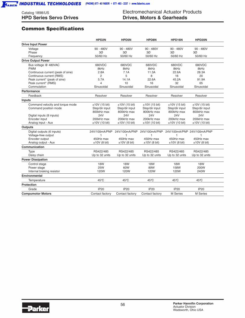
56 Parker Hannifin CorporationActuator DivisionWadsworth, Ohio USA
Catalog 1898/US Electromechanical Actuator ProductsDrives, Motors & Gearheads
HPD2N HPD5N HPD8N HPD16N HPD20N
Drive Input Power
Voltage 90 - 480V 90 - 480V 90 - 480V 90 - 480V 90 - 480VPhase 3Ø 3Ø 3Ø 3Ø 3ØFrequency 50/60 Hz 50/60 Hz 50/60 Hz 50/60 Hz 50/60 Hz
Drive Output Power
Bus voltage @ 480VAC 680VDC 680VDC 680VDC 680VDC 680VDCPWM 8kHz 8kHz 8kHz 8kHz 8kHzContinuous current (peak of sine) 2.8A 7.1A 11.3A 22.6A 28.3AContinuous current (RMS) 2 5 8 16 20Peak current* (peak of sine) 5.7A 14.1A 22.6A 45.2A 91.9APeak current* (RMS) 4 10 16 32 65Commutation Sinusoidal Sinusoidal Sinusoidal Sinusoidal Sinusoidal
Performance
Feedback Resolver Resolver Resolver Resolver Resolver
Inputs
Command velocity and torque mode ±10V (15 bit) ±10V (15 bit) ±10V (15 bit) ±10V (15 bit) ±10V (15 bit)Command position mode Step/dir input Step/dir input Step/dir input Step/dir input Step/dir input
800kHz max 800kHz max 800kHz max 800kHz max 800kHz maxDigital inputs (8 inputs) 24V 24V 24V 24V 24VEncoder input 200kHz max 200kHz max 200kHz max 200kHz max 200kHz maxAnalog input - Aux ±10V (10 bit) ±10V (10 bit) ±10V (10 bit) ±10V (10 bit) ±10V (10 bit)
Outputs
Digital outputs (6 inputs) 24V/100mA/PNP 24V/100mA/PNP 24V/100mA/PNP 24V/100mA/PNP 24V/100mA/PNPVoltage-free output 1 1 1 1 1Encoder output 450Hz max 450Hz max 450Hz max 450Hz max 450Hz maxAnalog output - Aux ±10V (8 bit) ±10V (8 bit) ±10V (8 bit) ±10V (8 bit) ±10V (8 bit)
Communication
Type RS422/485 RS422/485 RS422/485 RS422/485 RS422/485Daisy chain Up to 32 units Up to 32 units Up to 32 units Up to 32 units Up to 32 units
Power Dissipation
Control stage 18W 18W 18W 18W 18WPower stage 25W 60W 89W 158W 200WInternal braking resistor 120W 120W 120W 120W 240W
Environmental
Temperature 45°C 45°C 45°C 45°C 45°C
ProtectionGrade IP20 IP20 IP20 IP20 IP20
Compumotor Motors Contact factory Contact factory Contact factory M Series M Series
HPD Series Servo Drives
Common Specifications

57 Parker Hannifin CorporationActuator DivisionWadsworth, Ohio USA
Catalog 1898/US Electromechanical Actuator ProductsDrives, Motors & Gearheads
Dri
ves,
Mo
tors
, G
ea
rhe
ad
s
Dri
ves
Gea
rhea
ds
Mo
tors
HPD24N HPD25N HPD35N HPD45N HPD67N
Drive Input Power
Voltage 90 - 480V 90 - 480V 90 - 480V 90 - 480V 90 - 480VPhase 3Ø 3Ø 3Ø 3Ø 3ØFrequency 50/60 Hz 50/60 Hz 50/60 Hz 50/60 Hz 50/60 Hz
Drive Output Power
Bus voltage @ 480VAC 680VDC 680VDC 680VDC 680VDC 680VDCPWM 8kHz 8kHz 8kHz 8kHz 8kHzContinuous current (peak of sine) 33.9A 35.4A 49.5A 63.6A 94.7AContinuous current (RMS) 24 25 35 45 67Peak current* (peak of sine) 70.7A 70.7A 74.9A 94.7A 141.4APeak current* (RMS) 50 50 53 67 100Commutation Sinusoidal Sinusoidal Sinusoidal Sinusoidal Sinusoidal
Performance
Feedback Resolver Resolver Resolver Resolver Resolver
Inputs
Command velocity and torque mode ±10V (15 bit) ±10V (15 bit) ±10V (15 bit) ±10V (15 bit) ±10V (15 bit)Command position mode Step/dir input Step/dir input Step/dir input Step/dir input Step/dir input
800kHz max 800kHz max 800kHz max 800kHz max 800kHz maxDigital inputs (2+2 inputs) 24V 24V 24V 24V 24VEncoder input 200kHz max 200kHz max 200kHz max 200kHz max 200kHz maxAnalog input - Aux ±10V (10 bit) ±10V (10 bit) ±10V (10 bit) ±10V (10 bit) ±10V (10 bit)
Outputs
Digital outputs (2 inputs) 24V/100mA/PNP 24V/100mA/PNP 24V/100mA/PNP 24V/100mA/PNP 24V/100mA/PNPVoltage-free output 1 1 1 1 1Encoder output 450Hz max 450Hz max 450Hz max 450Hz max 450Hz maxAnalog output - Aux ±10V (8 bit) ±10V (8 bit) ±10V (8 bit) ±10V (8 bit) ±10V (8 bit)
Communication
Type RS422/485 RS422/485 RS422/485 RS422/485 RS422/485Daisy chain Up to 32 units Up to 32 units Up to 32 units Up to 32 units Up to 32 units
Dissipation
Control stage 18W 30W 30W 30W 30WPower stage 246W 250W 297W 370W 470WInternal braking resistor 240W 400W 400W 400W 400W
Environmental
Temperature 45°C 45°C 45°C 45°C 45°C
ProtectionGrade IP20 IP20 IP20 IP20 IP20
Compumotor Motors M Series M Series M Series M Series M Series
HPD Series Servo Drives
Common Specifications
Series Description
HPD2N Digital servo drive with 2 RMS continuous current
HPD5N Digital servo drive with 5 RMS continuous current
HPD8N Digital servo drive with 8 RMS continuous current
HPD16N Digital servo drive with 16 RMS continuous current
HPD20N Digital servo drive with 20 RMS continuous current
HPD24N Digital servo drive with 24 RMS continuous current
HPD25N Digital servo drive with 25 RMS continuous current
HPD35N Digital servo drive with 35 RMS continuous current
HPD45N Digital servo drive with 45 RMS continuous current
HPD67N Digital servo drive with 67 RMS continuous current
Ordering Information
NOTE: See Compax3 ordering information for motor cables.

58 Parker Hannifin CorporationActuator DivisionWadsworth, Ohio USA
Catalog 1898/US Electromechanical Actuator ProductsDrives, Motors & GearheadsHPD Series Servo Drives
Motor Speed-Torque Performance CurvesHPD with M Series motors, 105, 145 and 205mm frame, resolver feedback, 480 VAC
0 1000 2000 3000 4000 5000 60000
40
80
120
160
200
0
4.48
8.97
13.4
17.9
22.4
0 1000 2000 3000 4000 5000 60000
50
100
150
200
250
300
0
5.6
11.2
16.8
22.4
28.0
33.6
0 500 1000 1500 2000 2500 3000 3500 4000 45000
100
200
300
400
500
0
11.2
22.4
33.6
44.8
56.0
0 500 1000 1500 2000 2500 3000 3500 4000 45000
200
400
600
800
1000
0
22.4
44.8
67.3
89.7
112
0 500 1000 1500 2000 2500 3000 3500 4000 45000
100
200
300
400
500
600
700
0
11.2
22.4
33.6
44.8
56.0
67.2
78.5
0 500 1000 1500 2000 2500 3000 3500 4000 45000
200
400
600
800
1000
0
22.4
44.8
67.3
89.7
112
0 500 1000 1500 2000 2500 3000 3500 4000 45000
200
400
600
800
0
22.4
44.8
67.3
89.7
0 500 1000 1500 2000 2500 3000 3500 4000 45000
200
400
600
800
1000
0
22.4
44.8
67.3
89.7
112
0 500 1000 1500 2000 2500 30000
200
400
600
800
1000
1200
0
22.4
44.8
67.3
89.7
112
134
0 500 1000 1500 2000 2500 30000
400
800
1200
1600
0
44.8
89.7
134
179
M1053KR/HPD16
Speed (RPM)
Torq
ue (
Lb-in
) Torque (Nm
)
M1054KR/HPD24
Speed (RPM)
Torq
ue (
Lb-in
) Torque (Nm
)
M1453LR/HPD35
Speed (RPM)
Torq
ue (
Lb-in
) Torque (Nm
)
M1453LR/HPD67
Speed (RPM)
Torq
ue (
Lb-in
) Torque (Nm
)
M1454NR/HPD45
Speed (RPM)
Torq
ue (
Lb-in
) Torque (Nm
)
M1454NR/HPD67
Speed (RPM)
Torq
ue (
Lb-in
) Torque (Nm
)
M1455PR/HPD45
Speed (RPM)
Torq
ue (
Lb-in
) Torque (Nm
)
M1455PR/HPD67
Speed (RPM)
Torq
ue (
Lb-in
) Torque (Nm
)
M2052PR/HPD45
Speed (RPM)
Torq
ue (
Lb-in
) Torque (Nm
)
0 500 1000 1500 2000 2500 30000
400
800
1200
1600
0
44.8
89.7
134
179
0 500 1000 1500 2000 2500 30000
400
800
1200
1600
0
44.8
89.7
134
179
M2053RR/HPD67
Speed (RPM)
Torq
ue (
Lb-in
) Torque (Nm
)
M2054SR/HPD67
Speed (RPM)
Torq
ue (
Lb-in
) Torque (Nm
)
M2052PR/HPD67
Speed (RPM)
Torq
ue (
Lb-in
) Torque (Nm
)
CONTINUOUS PEAK (680V)

59 Parker Hannifin CorporationActuator DivisionWadsworth, Ohio USA
Catalog 1898/US Electromechanical Actuator ProductsDrives, Motors & Gearheads
Dri
ves,
Mo
tors
, G
ea
rhe
ad
s
Dri
ves
Gea
rhea
ds
Mo
tors
BE Series Servo Motors
BE SeriesHigh-Torque Design, Low-Cost PackageThe increased torque of the BE Series motors is the resultof 8 magnetic poles on the rotor instead of the traditionalfour.The cost reduction is achieved from their open laminationdesign. Unlike traditional servo motors, the BE Seriesmotors do not have a metal housing. Instead, thelaminations of the motor stator are shaped into the body ofthe motor. This design reduces both material costs and timerequired assembling the motor.The BE Series motors are created using Compumotor'sproven bridged stator design. This two-piece laminationdesign simplifies the manufacturing process, creatingfurther cost savings. The bridged stator construction alsoresults in less audible noise being generated by the motor.BE Series motors are available with integrated planetarygearheads in ratios up to 100:1. Our unique packageintegrates the gearhead pinion into the motor shaft,reducing the overall package length by up to 2 inches.
BE Series Features• Size 23 and 34
• 3 to 46 lb-in continuous torque
• Brushless construction
• High torque density packaging
• Bridged stator design – quiet operation
• High-performance neodymium magnets
• Thermostat protected
• 2000 line encoder standard
• Resolver feedback option
• Connectorization choices
• CE (LVD) compliant
Part Numbering System
BE J- N MS N
BE Series Frame,Magnet Length
230 341231 342232 343
WindingIdentifyingcharacter
C, D, F, J, K, L,etc.
FeedbackJ - 2000 ppr
encoder
R - Resolver3
ShaftingN - Normal
F - Flat
K - Keyway3
ConnectionFO1 - Flying leads w/plastic encoder cover
FL1 - Flyingleads
w/ connectorhousing
101 - 10’ cable
MS2 - Military style
TQ1,2 - Trap drive
PS - PS style
OptionsN - None
B - Brake3
GXX - Gearhead3,4
342 H
1 Encoder feedback motors only2 Refer to “Wiring and Cable Specifications” section for connector wiring3 Not available on size 164 Specify “K” shaft option with gearheads

60 Parker Hannifin CorporationActuator DivisionWadsworth, Ohio USA
Catalog 1898/US Electromechanical Actuator ProductsDrives, Motors & GearheadsBE Series Servo Motors
Specifications – Size 23, Encoder Feedback
Specifications – Size 23, Resolver Feedback
1 @25°C ambient, 150°C winding temperature, motor connected to a10" x 10" x 1/4" aluminum mounting plate; @40°C ambient deratephase currents and torques by 12%.
2 Operation with 340 VDC bus. Maximum speed is 5000 RPM. Forhigher speed operation, please call the factory.
3 Value is measured peak of sine wave.
4 ±30%, Line-to-Line, inductance bridge measurement @ 1 kHz.
5 Initial winding temperature must be 60°C or less before peak current isapplied.
6 DC current through a pair of motor phases of a trapezoidally (six state)commutated motor.
7 Peak of the sinusoidal current in any phase for a sinusoidallycommutated motor.
These specifications are based on theoretical motor performance and are not specific to any amplifier.
Parameter Symbol Units BE230D BE230F BE231D BE231F BE232D BE232F BE233D BE233F
Stall Torque Continuous1 Tcs lb-in 3.4 3.3 6.0 5.9 9.9 9.7 13.0 13.3oz-in 54 53 96 94 159 155 207 213Nm 0.38 0.37 0.67 0.66 1.11 1.08 1.45 1.49
Stall Current Continuous1,3,7 Ics (sine) Amps Peak 3.1 6.1 2.8 5.3 2.8 5.4 2.5 4.9Ics (trap) Amps DC 2.7 5.3 2.4 4.6 2.4 4.7 2.2 4.2
Peak Torque5 Tpk lb-in 10.1 10.0 18.0 17.7 29.7 29.0 38.9 40.0oz-in 161 160 289 283 476 464 622 640Nm 1.13 1.12 2.02 1.98 3.33 3.25 4.35 4.48
Peak Current3,5,7 Ipk (sine) Amps Peak 9.4 18.2 8.2 15.9 8.4 16.3 7.4 14.6
Peak Current5,6 Ipk (trap) Amps DC 8.1 15.8 7.1 13.8 7.3 14.1 6.5 12.7
Rated Speed2 ωr rpm 5000 5000 5000 5000 5000 5000 3750 5000
Torque @ Rated Speed Tr lb-in 2.9 2.9 5.2 5.1 8.2 8.0 11.3 10.7oz-in 47 47 83 81 131 128 180 171Nm 0.33 0.33 0.58 0.57 0.92 0.90 1.26 1.20
Shaft Power @ Rated Speed Po watts 174 174 307 300 484 473 499 632
Inductance4 L mH 15.43 4.10 32.30 8.65 42.66 11.12 61.39 16.28
Thermal Resistance Wind-Amb Rth w-a °C/watt 2.14 2.14 1.82 1.82 1.58 1.58 1.41 1.41
Motor Thermal Time Constant τth minutes 11.6 11.6 13.3 13.3 15.0 15.0 20.0 20.0
Electrical Time Constant τelec millisecs 3.38 3.36 4.63 4.65 5.53 5.42 5.59 5.71
Mechanical Time Constant τmch millisecs 1.2 1.2 0.8 0.8 0.6 0.6 0.6 0.5
Rotor Inertia J lb-in-sec2 4.6E-05 4.6E-05 8.0E-05 8.0E-05 1.5E-04 1.5E-04 2.1E-04 2.1E-04kg-m2 5.2E-06 5.2E-06 9.0E-06 9.0E-06 1.7E-05 1.7E-05 2.4E-05 2.4E-05
Weight # lbs 1.5 1.5 2.0 2.0 3.1 3.0 4.2 4.2kg 0.7 0.7 0.9 0.9 1.4 1.4 1.9 1.9
Parameter Symbol Units BE230D BE230F BE231D BE231F BE232D BE232F BE233D BE233F
Stall Torque Continuous1 Tcs lb-in 3.6 3.6 6.5 6.4 40.7 10.5 14.0 14.4oz-in 58 58 104 102 171 167 225 231Nm 0.41 0.40 0.73 0.71 1.20 1.17 1.57 1.61
Stall Current Continuous1,3,6 Ics (sine) Amps Peak 3.4 6.6 3.0 5.7 3.0 5.9 2.7 5.3
Peak Torque5 Tpk lb-in 10.9 10.8 19.5 19.1 32.1 31.4 42.1 43.2oz-in 174 173 312 306 513 502 674 692Nm 1.22 1.21 2.18 2.14 3.59 3.51 4.72 4.84
Peak Current3,5,7 Ipk (sine) Amps Peak 10.1 19.7 8.9 17.2 9.1 17.6 8.1 15.8
Rated Speed2 ωr rpm 5000 5000 5000 5000 5000 5000 3625 5000
Torque @ Rated Speed Tr lb-in 3.3 3.3 5.8 5.6 9.3 9.0 12.6 12.1oz-in 52 52 92 90 148 144 201 194Nm 0.36 0.36 0.64 0.63 1.04 1.01 1.41 1.36
Shaft Power @ Rated Speed Po watts 192 192 340 333 547 533 539 717
Inductance4 L mH 15.43 4.10 3230 8.65 42.66 11.12 61.39 16.28
Thermal Resistance Wind-Amb Rth w-a °C/watt 2.14 2.14 1.82 1.82 1.58 1.58 1.41 1.41
Motor Thermal Time Constant τth minutes 11.6 11.6 13.3 13.3 15.0 15.0 20.0 20.0
Electrical Time Constant τelec millisecs 3.38 3.36 4.63 4.65 5.53 5.51 5.59 5.71
Mechanical Time Constant τmch millisecs 1.2 1.2 0.8 0.8 0.6 0.6 0.6 0.5
Rotor Inertia J lb-in-sec2 4.6E-05 4.6E-05 8.0E-05 8.03-05 1.5E-04 1.5E-04 2.1E-04 2.1E-04kg-m2 5.2E-06 5.2E-06 9.0E-06 9.0E-06 1.7E-05 1.7E-05 2.4E-05 2.4E-05
Weight # lbs 1.5 1.5 2.0 2.0 3.1 3.1 4.2 4.2kg 0.7 0.7 0.9 0.9 1.4 1.4 1.9 1.9
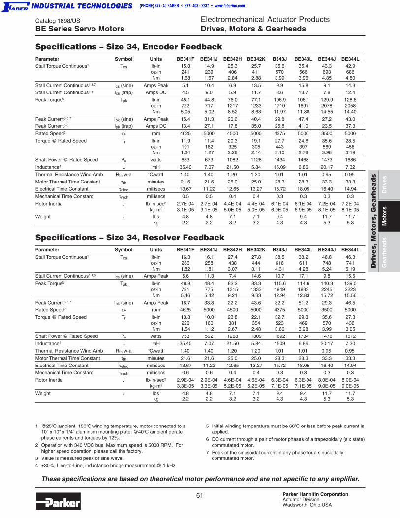
61 Parker Hannifin CorporationActuator DivisionWadsworth, Ohio USA
Catalog 1898/US Electromechanical Actuator ProductsDrives, Motors & Gearheads
Dri
ves,
Mo
tors
, G
ea
rhe
ad
s
Dri
ves
Gea
rhea
ds
Mo
tors
BE Series Servo Motors
Specifications – Size 34, Encoder Feedback
Specifications – Size 34, Resolver Feedback
1 @25°C ambient, 150°C winding temperature, motor connected to a10" x 10" x 1/4" aluminum mounting plate; @40°C ambient deratephase currents and torques by 12%.
2 Operation with 340 VDC bus. Maximum speed is 5000 RPM. Forhigher speed operation, please call the factory.
3 Value is measured peak of sine wave.
4 ±30%, Line-to-Line, inductance bridge measurement @ 1 kHz.
5 Initial winding temperature must be 60°C or less before peak current isapplied.
6 DC current through a pair of motor phases of a trapezoidally (six state)commutated motor.
7 Peak of the sinusoidal current in any phase for a sinusoidallycommutated motor.
These specifications are based on theoretical motor performance and are not specific to any amplifier.
Parameter Symbol Units BE341F BE341J BE342H BE342K B343J BE343L BE344J BE344L
Stall Torque Continuous1 Tcs lb-in 15.0 14.9 25.3 25.7 35.6 35.4 43.3 42.9oz-in 241 239 406 411 570 566 693 686Nm 1.68 1.67 2.84 2.88 3.99 3.96 4.85 4.80
Stall Current Continuous1,3,7 Ics (sine) Amps Peak 5.1 10.4 6.9 13.5 9.9 15.8 9.1 14.3
Stall Current Continuous1,6 Ics (trap) Amps DC 4.5 9.0 5.9 11.7 8.6 13.7 7.8 12.4
Peak Torque5 Tpk lb-in 45.1 44.8 76.0 77.1 106.9 106.1 129.9 128.6oz-in 722 717 1217 1233 1710 1697 2078 2058Nm 5.05 5.02 8.52 8.63 11.97 11.88 14.55 14.40
Peak Current3,5,7 Ipk (sine) Amps Peak 15.4 31.3 20.6 40.4 29.8 47.4 27.2 43.0
Peak Current5,6 Ipk (trap) Amps DC 13.4 27.1 17.8 35.0 25.8 41.0 23.5 37.3
Rated Speed2 ωr rpm 4625 5000 4500 5000 4375 5000 3500 5000
Torque @ Rated Speed Tr lb-in 11.9 11.4 20.3 19.1 27.7 24.8 35.6 28.5oz-in 191 182 325 305 443 397 569 456Nm 1.34 1.27 2.28 2.14 3.10 2.78 3.98 3.19
Shaft Power @ Rated Speed Po watts 653 673 1082 1128 1434 1468 1473 1686
Inductance4 L mH 35.40 7.07 21.50 5.84 15.09 6.86 20.17 7.32
Thermal Resistance Wind-Amb Rth w-a °C/watt 1.40 1.40 1.20 1.20 1.01 1.01 0.95 0.95
Motor Thermal Time Constant τth minutes 21.6 21.6 25.0 25.0 28.3 28.3 33.3 33.3
Electrical Time Constant τelec millisecs 13.67 11.22 12.65 13.27 15.72 18.05 16.40 14.94
Mechanical Time Constant τmch millisecs 0.5 0.5 0.4 0.4 0.3 0.3 0.3 0.3
Rotor Inertia J lb-in-sec2 2.7E-04 2.7E-04 4.4E-04 4.4E-04 6.1E-04 6.1E-04 7.2E-04 7.2E-04kg-m2 3.1E-05 3.1E-05 5.0E-05 5.0E-05 6.9E-05 6.9E-05 8.1E-05 8.1E-05
Weight # lbs 4.8 4.8 7.1 7.1 9.4 9.4 11.7 11.7kg 2.2 2.2 3.2 3.2 4.3 4.3 5.3 5.3
Parameter Symbol Units BE341F BE341J BE342H BE342K B343J BE343L BE344J BE344L
Stall Torque Continuous1 Tcs lb-in 16.3 16.1 27.4 27.8 38.5 38.2 46.8 46.3oz-in 260 258 438 444 616 611 748 741Nm 1.82 1.81 3.07 3.11 4.31 4.28 5.24 5.19
Stall Current Continuous1,3,6 Ics (sine) Amps Peak 5.6 11.3 7.4 14.6 10.7 17.1 9.8 15.5
Peak Torque5 Tpk lb-in 48.8 48.4 82.2 83.3 115.6 114.6 140.3 139.0oz-in 781 775 1315 1333 1849 1833 2245 2223Nm 5.46 5.42 9.21 9.33 12.94 12.83 15.72 15.56
Peak Current3,5,7 Ipk (sine) Amps Peak 16.7 33.8 22.2 43.6 32.2 51.2 29.3 46.5
Rated Speed2 ωr rpm 4625 5000 4500 5000 4375 5000 3500 5000
Torque @ Rated Speed Tr lb-in 13.8 10.0 23.8 22.1 32.7 29.3 35.6 27.3oz-in 220 160 381 354 523 469 570 436Nm 1.54 1.12 2.67 2.48 3.66 3.28 3.99 3.05
Shaft Power @ Rated Speed Po watts 753 592 1268 1309 1692 1734 1476 1612
Inductance4 L mH 35.40 7.07 21.50 5.84 1509 6.86 20.17 7.30
Thermal Resistance Wind-Amb Rth w-a °C/watt 1.40 1.40 1.20 1.20 1.01 1.01 0.95 0.95
Motor Thermal Time Constant τth minutes 21.6 21.6 25.0 25.0 28.3 28.3 33.3 33.3
Electrical Time Constant τelec millisecs 13.67 11.22 12.65 13.27 15.72 18.05 16.40 14.94
Mechanical Time Constant τmch millisecs 0.6 0.6 0.4 0.4 0.3 0.3 0.3 0.3
Rotor Inertia J lb-in-sec2 2.9E-04 2.9E-04 4.6E-04 4.6E-04 6.3E-04 6.3E-04 8.0E-04 8.0E-04kg-m2 3.3E-05 3.3E-05 5.2E-05 5.2E-05 7.1E-05 7.1E-05 9.0E-05 9.0E-05
Weight # lbs 4.8 4.8 7.1 7.1 9.4 9.4 11.7 11.7kg 2.2 2.2 3.2 3.2 4.3 4.3 5.3 5.3
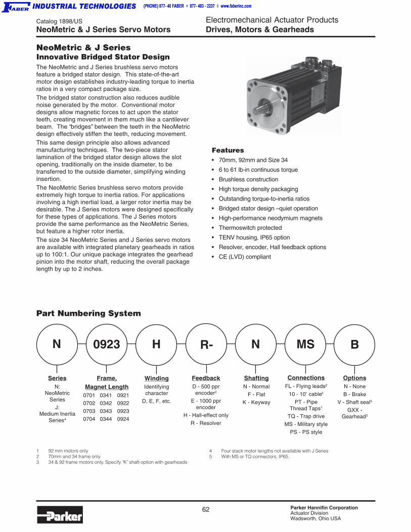
62 Parker Hannifin CorporationActuator DivisionWadsworth, Ohio USA
Catalog 1898/US Electromechanical Actuator ProductsDrives, Motors & GearheadsNeoMetric & J Series Servo Motors
NeoMetric & J SeriesInnovative Bridged Stator DesignThe NeoMetric and J Series brushless servo motorsfeature a bridged stator design. This state-of-the-artmotor design establishes industry-leading torque to inertiaratios in a very compact package size.The bridged stator construction also reduces audiblenoise generated by the motor. Conventional motordesigns allow magnetic forces to act upon the statorteeth, creating movement in them much like a cantileverbeam. The “bridges” between the teeth in the NeoMetricdesign effectively stiffen the teeth, reducing movement.This same design principle also allows advancedmanufacturing techniques. The two-piece statorlamination of the bridged stator design allows the slotopening, traditionally on the inside diameter, to betransferred to the outside diameter, simplifying windinginsertion.The NeoMetric Series brushless servo motors provideextremely high torque to inertia ratios. For applicationsinvolving a high inertial load, a larger rotor inertia may bedesirable. The J Series motors were designed specificallyfor these types of applications. The J Series motorsprovide the same performance as the NeoMetric Series,but feature a higher rotor inertia.The size 34 NeoMetric Series and J Series servo motorsare available with integrated planetary gearheads in ratiosup to 100:1. Our unique package integrates the gearheadpinion into the motor shaft, reducing the overall packagelength by up to 2 inches.
Features• 70mm, 92mm and Size 34
• 6 to 61 lb-in continuous torque
• Brushless construction
• High torque density packaging
• Outstanding torque-to-inertia ratios
• Bridged stator design – quiet operation
• High-performance neodymium magnets
• Thermoswitch protected
• TENV housing, IP65 option
• Resolver, encoder, Hall feedback options
• CE (LVD) compliant
Part Numbering System
N 0923 R- N MS BH
SeriesN:
NeoMetricSeries
J:Medium Inertia
Series4
Frame,Magnet Length
0701 0341 0921
0702 0342 0922
0703 0343 0923
0704 0344 0924
WindingIdentifyingcharacter
D, E, F, etc.
FeedbackD - 500 pprencoder2
E - 1000 pprencoder
H - Hall-effect only
R - Resolver
ShaftingN - Normal
F - Flat
K - Keyway
ConnectionsFL - Flying leads2
10 - 10’ cable2
PT - PipeThread Taps1
TQ - Trap drive
MS - Military style
PS - PS style
OptionsN - None
B - Brake
V - Shaft seal5
GXX -Gearhead3
1 92 mm motors only2 70mm and 34 frame only3 34 & 92 frame motors only. Specify “K” shaft option with gearheads
4 Four stack motor lengths not available with J Series5 With MS or TQ connectors, IP65.
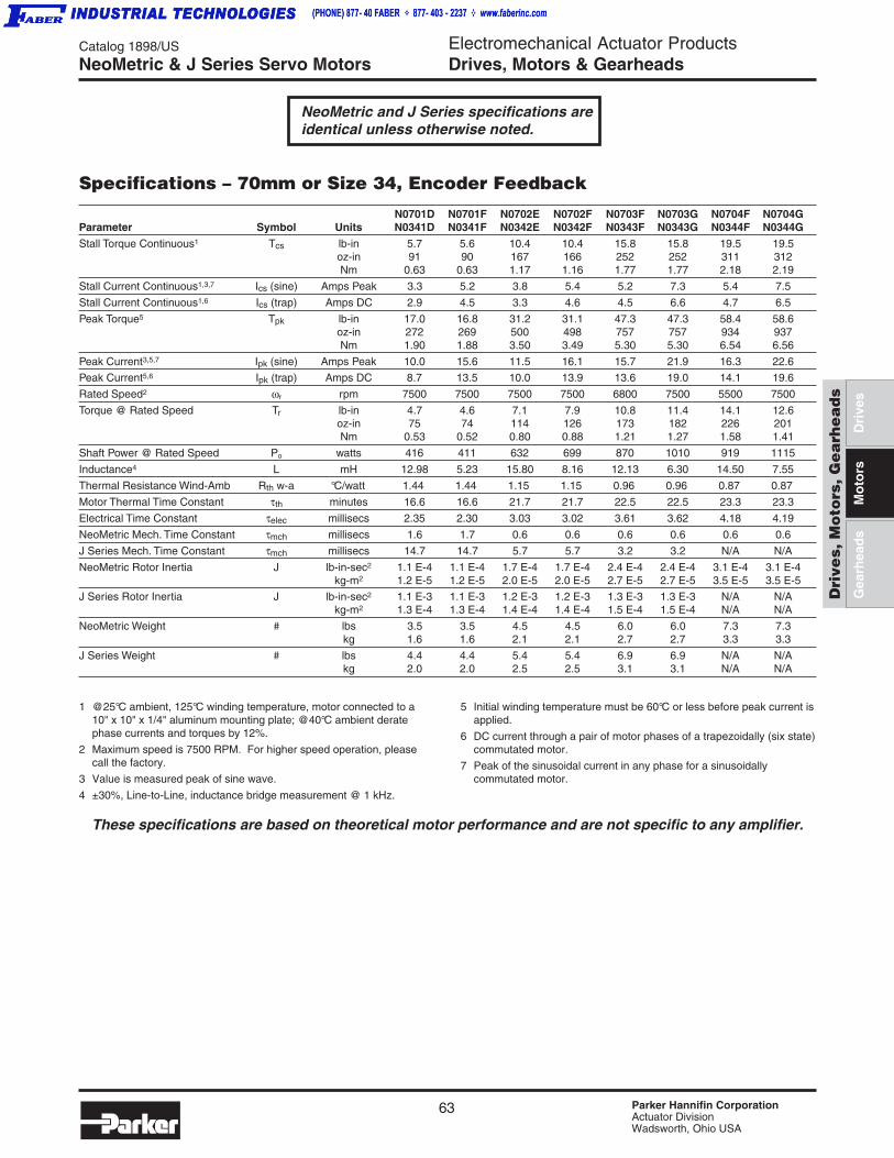
63 Parker Hannifin CorporationActuator DivisionWadsworth, Ohio USA
Catalog 1898/US Electromechanical Actuator ProductsDrives, Motors & Gearheads
Dri
ves,
Mo
tors
, G
ea
rhe
ad
s
Dri
ves
Gea
rhea
ds
Mo
tors
Specifications – 70mm or Size 34, Encoder Feedback
N0701D N0701F N0702E N0702F N0703F N0703G N0704F N0704GParameter Symbol Units N0341D N0341F N0342E N0342F N0343F N0343G N0344F N0344G
Stall Torque Continuous1 Tcs lb-in 5.7 5.6 10.4 10.4 15.8 15.8 19.5 19.5oz-in 91 90 167 166 252 252 311 312Nm 0.63 0.63 1.17 1.16 1.77 1.77 2.18 2.19
Stall Current Continuous1,3,7 Ics (sine) Amps Peak 3.3 5.2 3.8 5.4 5.2 7.3 5.4 7.5
Stall Current Continuous1,6 Ics (trap) Amps DC 2.9 4.5 3.3 4.6 4.5 6.6 4.7 6.5
Peak Torque5 Tpk lb-in 17.0 16.8 31.2 31.1 47.3 47.3 58.4 58.6oz-in 272 269 500 498 757 757 934 937Nm 1.90 1.88 3.50 3.49 5.30 5.30 6.54 6.56
Peak Current3,5,7 Ipk (sine) Amps Peak 10.0 15.6 11.5 16.1 15.7 21.9 16.3 22.6
Peak Current5,6 Ipk (trap) Amps DC 8.7 13.5 10.0 13.9 13.6 19.0 14.1 19.6
Rated Speed2 ωr rpm 7500 7500 7500 7500 6800 7500 5500 7500
Torque @ Rated Speed Tr lb-in 4.7 4.6 7.1 7.9 10.8 11.4 14.1 12.6oz-in 75 74 114 126 173 182 226 201Nm 0.53 0.52 0.80 0.88 1.21 1.27 1.58 1.41
Shaft Power @ Rated Speed Po watts 416 411 632 699 870 1010 919 1115
Inductance4 L mH 12.98 5.23 15.80 8.16 12.13 6.30 14.50 7.55
Thermal Resistance Wind-Amb Rth w-a °C/watt 1.44 1.44 1.15 1.15 0.96 0.96 0.87 0.87
Motor Thermal Time Constant τth minutes 16.6 16.6 21.7 21.7 22.5 22.5 23.3 23.3
Electrical Time Constant τelec millisecs 2.35 2.30 3.03 3.02 3.61 3.62 4.18 4.19
NeoMetric Mech. Time Constant τmch millisecs 1.6 1.7 0.6 0.6 0.6 0.6 0.6 0.6
J Series Mech. Time Constant τmch millisecs 14.7 14.7 5.7 5.7 3.2 3.2 N/A N/A
NeoMetric Rotor Inertia J lb-in-sec2 1.1 E-4 1.1 E-4 1.7 E-4 1.7 E-4 2.4 E-4 2.4 E-4 3.1 E-4 3.1 E-4kg-m2 1.2 E-5 1.2 E-5 2.0 E-5 2.0 E-5 2.7 E-5 2.7 E-5 3.5 E-5 3.5 E-5
J Series Rotor Inertia J lb-in-sec2 1.1 E-3 1.1 E-3 1.2 E-3 1.2 E-3 1.3 E-3 1.3 E-3 N/A N/Akg-m2 1.3 E-4 1.3 E-4 1.4 E-4 1.4 E-4 1.5 E-4 1.5 E-4 N/A N/A
NeoMetric Weight # lbs 3.5 3.5 4.5 4.5 6.0 6.0 7.3 7.3kg 1.6 1.6 2.1 2.1 2.7 2.7 3.3 3.3
J Series Weight # lbs 4.4 4.4 5.4 5.4 6.9 6.9 N/A N/Akg 2.0 2.0 2.5 2.5 3.1 3.1 N/A N/A
1 @25°C ambient, 125°C winding temperature, motor connected to a10" x 10" x 1/4" aluminum mounting plate; @40°C ambient deratephase currents and torques by 12%.
2 Maximum speed is 7500 RPM. For higher speed operation, pleasecall the factory.
3 Value is measured peak of sine wave.
4 ±30%, Line-to-Line, inductance bridge measurement @ 1 kHz.
5 Initial winding temperature must be 60°C or less before peak current isapplied.
6 DC current through a pair of motor phases of a trapezoidally (six state)commutated motor.
7 Peak of the sinusoidal current in any phase for a sinusoidallycommutated motor.
These specifications are based on theoretical motor performance and are not specific to any amplifier.
NeoMetric and J Series specifications areidentical unless otherwise noted.
NeoMetric & J Series Servo Motors

64 Parker Hannifin CorporationActuator DivisionWadsworth, Ohio USA
Catalog 1898/US Electromechanical Actuator ProductsDrives, Motors & Gearheads
Specifications – 70mm or Size 34, Resolver Feedback
1 @25°C ambient, 150°C winding temperature, motor connected to a10" x 10" x 1/4" aluminum mounting plate; @40°C ambient deratephase currents and torques by 12%.
2 Maximum speed is 7500 RPM. For higher speed operation, pleasecall the factory.
3 Value is measured peak of sine wave.
4 ±30%, Line-to-Line, inductance bridge measurement @ 1 kHz.
5 Initial winding temperature must be 60°C or less before peak current isapplied.
6 Peak of the sinusoidal current in any phase for a sinusoidallycommutated motor.
These specifications are based on theoretical motor performance and are not specific to any amplifier.
N0701D N0701F N0702E N0702F N0703F N0703G N0704F N0704GParameter Symbol Units N0341D N0341F N0342E N0342F N0343F N0343G N0344F N0344G
Stall Torque Continuous1 Tcs lb-in 6.3 6.3 11.6 11.6 17.6 17.6 21.8 21.8oz-in 101 100 186 186 282 282 348 349Nm 0.71 0.70 1.30 1.30 1.97 1.97 2.44 2.44
Stall Current Continuous1,3,6 Ics (sine) Amps Peak 3.7 5.8 4.3 6.0 5.9 8.2 6.1 8.4
Peak Torque5 Tpk lb-in 19.0 18.8 34.9 34.8 52.9 52.9 65.3 65.4oz-in 304 300 559 557 846 846 1045 1047Nm 2.13 2.10 3.91 3.90 5.92 5.92 7.32 7.33
Peak Current3,5,6 Ipk (sine) Amps Peak 11.2 17.5 12.9 17.9 17.6 24.5 18.2 25.3
Rated Speed2 ωr rpm 7500 7500 7100 7500 6600 7500 5500 7500
Torque @ Rated Speed Tr lb-in 5.4 5.3 8.6 9.3 12.8 13.6 16.1 15.0oz-in 86 85 138 149 205 217 257 240Nm 0.60 0.60 0.97 1.04 1.44 1.52 1.80 1.68
Shaft Power @ Rated Speed Po watts 477 472 725 827 1001 1204 1045 1331
Inductance4 L mH 12.98 5.23 15.80 8.16 12.13 6.30 14.50 7.55
Thermal Resistance Wind-Amb Rth w-a °C/watt 1.44 1.44 1.15 1.15 0.96 0.96 0.87 0.87
Motor Thermal Time Constant τth minutes 16.6 16.6 21.7 21.7 22.5 22.5 23.3 23.3
Electrical Time Constant τelec millisecs 2.35 2.30 3.03 3.02 3.61 3.62 4.18 4.19
NeoMetric Mech. Time Constant τmch millisecs 1.6 1.7 0.9 0.9 0.6 0.6 0.6 0.6
J Series Mech. Time Constant τmch millisecs 14.7 14.7 5.7 5.7 3.2 3.2 N/A N/A
NeoMetric Rotor Inertia J lb-in-sec2 1.3 E-4 1.3 E-4 2.0 E-4 2.0 E-4 2.6 E-4 2.6 E-4 3.3 E-4 3.3 E-4kg-m2 1.5 E-5 1.5 E-5 2.2 E-5 2.2 E-5 3.0 E-5 3.0 E-5 3.7 E-5 3.7 E-5
J Series Rotor Inertia J lb-in-sec2 1.1 E-3 1.1 E-3 1.2 E-3 1.2 E-3 1.3 E-3 1.3 E-3 N/A N/Akg-m2 1.3 E-4 1.3 E-4 1.4 E-4 1.4 E-4 1.5 E-4 1.5 E-4 N/A N/A
NeoMetric Weight # lbs 3.5 3.5 4.5 4.5 6.0 6.0 7.3 7.3kg 1.6 1.6 2.1 2.1 2.7 2.7 3.3 3.3
J Series Weight # lbs 4.4 4.4 5.4 5.4 6.9 6.9 N/A N/Akg 2.0 2.0 2.5 2.5 3.1 3.1 N/A N/A
NeoMetric & J Series Servo Motors
NeoMetric and J Series specifications areidentical unless otherwise noted.

65 Parker Hannifin CorporationActuator DivisionWadsworth, Ohio USA
Catalog 1898/US Electromechanical Actuator ProductsDrives, Motors & Gearheads
Dri
ves,
Mo
tors
, G
ea
rhe
ad
s
Dri
ves
Gea
rhea
ds
Mo
tors
NeoMetric & J Series Servo Motors
Specifications – 92mm, Encoder FeedbackParameter Symbol Units N0921F N0921G N0922G N0922J N0923H N0923K N0924J N0923K
Stall Torque Continuous1 Tcs lb-in 15.5 15.6 27.6 28.3 41.3 40.6 54.6 54.8oz-in 249 249 442 453 660 650 873 876Nm 1.74 1.74 3.09 3.17 4.62 4.55 6.11 6.14
Stall Current Continuous1,3,7 Ics (sine) Amps Peak 4.7 6.6 6.5 10.1 10.0 17.4 10.8 15.2
Stall Current Continuous1,6 Ics (trap) Amps DC 4.1 5.7 5.6 8.7 8.6 15.1 9.4 13.2
Peak Torque5 Tpk lb-in 46.6 46.7 82.9 83.5 123.7 121.9 163.8 164.3oz-in 746 747 1327 1336 1979 1951 2620 2629Nm 5.22 5.23 9.29 9.35 13.85 13.66 18.34 18.41
Peak Current3,5,7 Ipk (sine) Amps Peak 14.2 19.7 19.5 30.3 29.9 52.2 32.5 45.6
Peak Current5,6 Ipk (trap) Amps DC 12.3 17.1 26.9 26.2 25.9 45.2 28.2 39.5
Rated Speed2 ωr rpm 6000 7500 4650 7300 4700 7500 3750 5250
Torque @ Rated Speed Tr lb-in 11.8 11.3 20.4 16.3 30.4 28.8 41.0 39.1oz-in 188 181 326 260 487 461 656 626Nm 1.32 1.27 2.28 1.82 3.41 3.23 4.59 4.38
Shaft Power @ Rated Speed Po watts 834 1004 1121 1404 1689 2557 1820 2431
Inductance4 L mH 17.11 8.99 14.72 6.18 14.95 4.78 20.60 10.51
Thermal Resistance Wind-Amb Rth w-a °C/watt 1.06 1.06 0.91 0.91 0.7 0.7 0.62 0.62
Motor Thermal Time Constant τth minutes 21.6 21.6 30 30 35 35 37 37
Electrical Time Constant τelec millisecs 4.60 4.63 6.34 6.44 11.68 11.38 16.89 16.95
NeoMetric Mech. Time Constant τmch millisecs 0.8 0.8 0.5 0.5 0.4 0.5 0.4 0.4
J Series Mech. Time Constant τmch millisecs 10.0 10.0 3.9 3.9 2.4 2.4 N/A N/A
NeoMetric Rotor Inertia J lb-in-sec2 3.6 E-4 3.6 E-4 6.2 E-4 6.2 E-4 8.8 E-4 8.8 E-4 1.1 E-3 1.1 E-3kg-m2 4.1 E-5 4.1 E-5 7.0 E-5 7.0 E-5 1.0 E-4 1.0 E-4 1.3 E-4 1.3 E-4
J Series Rotor Inertia J lb-in-sec2 4.2 E-3 4.2 E-3 4.5 E-3 4.5 E-3 4.8 E-3 4.8 E-3 N/A N/Akg-m2 4.8 E-4 4.8 E-4 5.1 E-4 5.1 E-4 5.4 E-4 5.4 E-4 N/A N/A
NeoMetric Weight # lbs 8.1 8.1 11.7 11.7 15.1 15.1 18.0 18.0kg 3.7 3.7 5.3 5.3 6.9 6.9 8.2 8.2
J Series Weight # lbs 9.9 9.9 13.5 13.5 16.9 16.9 N/A N/Akg 4.5 4.5 6.1 6.1 7.7 7.7 N/A N/A
1 @25°C ambient, 125°C winding temperature, motor connected to a10" x 10" x 1/4" aluminum mounting plate; @40°C ambient deratephase currents and torques by 12%.
2 Operation with 340 VDC bus. Maximum speed is 5000 RPM. Forhigher speed operation, please call the factory.
3 Value is measured peak of sine wave.
4 ±30%, Line-to-Line, inductance bridge measurement @ 1 kHz.
5 Initial winding temperature must be 60°C or less before peak current isapplied.
6 DC current through a pair of motor phases of a trapezoidally (six state)commutated motor.
7 Peak of the sinusoidal current in any phase for a sinusoidallycommutated motor.
These specifications are based on theoretical motor performance and are not specific to any amplifier.
NeoMetric and J Series specifications areidentical unless otherwise noted.

66 Parker Hannifin CorporationActuator DivisionWadsworth, Ohio USA
Catalog 1898/US Electromechanical Actuator ProductsDrives, Motors & GearheadsNeoMetric & J Series Servo Motors
Specifications – 92mm, Resolver Feedback
1 @25°C ambient, 150°C winding temperature, motor connected to a10" x 10" x 1/4" aluminum mounting plate; @40°C ambient deratephase currents and torques by 12%.
2 Operation with 340 VDC bus. Maximum speed is 5000 RPM. Forhigher speed operation, please call the factory.
3 Value is measured peak of sine wave.
4 ±30%, Line-to-Line, inductance bridge measurement @ 1 kHz.
5 Initial winding temperature must be 60°C or less before peak current isapplied.
6 Peak of the sinusoidal current in any phase for a sinusoidallycommutated motor.
These specifications are based on theoretical motor performance and are not specific to any amplifier.
Parameter Symbol Units N0921F N0921G N0922G N0922J N0923H N0923K N0924J N0923K
Stall Torque Continuous1 Tcs lb-in 17.4 17.4 30.9 31.1 46.1 45.4 61.1 61.3oz-in 278 279 495 498 737 727 977 980Nm 1.95 1.95 3.47 3.49 5.16 5.09 6.84 6.86
Stall Current Continuous1,3,6 Ics (sine) Amps Peak 5.3 7.4 7.3 11.3 11.1 19.4 12.1 17.0
Peak Torque5 Tpk lb-in 52.1 52.3 92.8 93.4 138.3 136.3 183.1 183.8oz-in 834 836 1484 1494 2212 2181 2929 2940Nm 5.84 5.85 10.39 10.46 15.48 15.27 20.50 20.58
Peak Current3,5,6 Ipk (sine) Amps Peak 15.9 22.1 21.8 33.8 33.4 58.3 36.4 51.0
Rated Speed2 ωr rpm 6000 7500 4700 7100 4500 7500 3600 5200
Torque @ Rated Speed Tr lb-in 12.7 12.9 25.9 23.3 34.1 30.1 46.3 42.7oz-in 203 207 414 372 545 481 740 683Nm 1.42 1.45 2.90 2.60 3.82 3.37 5.18 4.78
Shaft Power @ Rated Speed Po watts 901 1148 1378 1954 1814 2668 1970 2627
Inductance4 L mH 17.11 8.99 14.72 6.18 14.95 4.78 20.60 10.51
Thermal Resistance Wind-Amb Rth w-a °C/watt 1.06 1.06 0.91 0.91 0.7 0.7 0.62 0.62
Motor Thermal Time Constant τth minutes 21.6 21.6 30 30 35 35 36.6 36.6
Electrical Time Constant τelec millisecs 4.60 4.63 6.34 6.44 11.68 11.38 16.89 16.95
NeoMetric Mech. Time Constant τmch millisecs 1.2 1.2 0.7 0.7 0.5 0.5 0.4 0.4
J Series Mech. Time Constant τmch millisecs 10.0 10.0 3.9 3.9 2.4 2.4 N/A N/A
NeoMetric Rotor Inertia J lb-in-sec2 5.3 E-4 5.3 E-4 7.9 E-4 7.9 E-4 1.1 E-3 1.1 E-3 1.3 E-3 1.3 E-3kg-m2 6.0 E-5 6.0 E-5 9.0 E-5 9.0 E-5 1.2 E-4 1.2 E-4 1.5 E-4 1.5 E-4
J Series Rotor Inertia J lb-in-sec2 4.4 E-3 4.4 E-3 4.7 E-3 4.7 E-3 5.0 E-3 5.0 E-3 N/A N/Akg-m2 4.9 E-4 4.9 E-4 5.3 E-4 5.3 E-4 5.7 E-4 5.7 E-4 N/A N/A
NeoMetric Weight # lbs 8.1 8.1 11.7 11.7 15.1 15.1 18.0 18.0kg 3.7 3.7 5.3 5.3 6.9 6.9 8.2 8.2
J Series Weight # lbs 9.9 9.9 13.5 13.5 16.9 16.9 N/A N/Akg 4.5 4.5 6.1 6.1 7.7 7.7 N/A N/A
NeoMetric and J Series specifications areidentical unless otherwise noted.

67 Parker Hannifin CorporationActuator DivisionWadsworth, Ohio USA
Catalog 1898/US Electromechanical Actuator ProductsDrives, Motors & Gearheads
Dri
ves,
Mo
tors
, G
ea
rhe
ad
s
Dri
ves
Gea
rhea
ds
Mo
tors
SMN Series Motors
SMN SeriesHigh-Torque Design, Compact PackageParker’s SMN series of rotary servo motors combines ahighperformance segmented stator design with competitivepricing for today’s demanding servo applications. Themodern eightpole segmented stator architecture producesextremely high torque values for a given motor volume. TheSMN motor family is offered in frame sizes ranging from 60mm to 142 mm and is available with resolver, quadratureencoder or high-resolution SinCos feedback devices.
SMN Motor Features• High performance per dollar
• High torque density package
• 1.7 – 14.5 N-m continuous torque range
• Brushless construction
• Resolver, encoder or SinCos (absolute) feedback
• Class H winding
• IP65 rating
Part Numbering System
SMN
Series FrameSize
060 = 60mm
082 = 82mm
100 = 100mm
115 = 115mm
142 = 142mm
StackLength
2
WindingP
Q
S
T
V
Z
FeedbackType
ConnectorP=PS style
OptionsN=None
B=Holding Brake
082 2 S 4 1- K P N
FeedbackResolution
ShaftK=Keyway
41 = Resolver, single speed
2F = Quadrature encoder,2048 line
5D =SinCos w/Hiperface™absolute encoder(Stegmann)

68 Parker Hannifin CorporationActuator DivisionWadsworth, Ohio USA
Catalog 1898/US Electromechanical Actuator ProductsDrives, Motors & Gearheads
Parameter Symbol Units SMN1152Q SMN152T SMN1422P SMN1422S
Stall Torque Cont [1] Tcs lb-in 83.96 84.91 128.72 124.60Nm 9.49 9.59 14.54 14.08
Stall Current Cont [1] Ics(RMS) Amps RMS 5.72 10.86 9.44 15.05
Peak Torque [6] Tpk lb-in 268.48 267.48 405.47 392.50Nm 30.36 30.22 45.81 44.35
Peak Current [6] Ipk(RMS) Amps RMS 18.3 34.2 29.7 47.4
Rated Speed [2] Wr rpm 4200 5000 4400 5000
Torque @ Rated Speed Tr lb-in 70.55 67.09 109.58 101.85Nm 7.97 7.58 12.38 11.51
Shaft Power @Rated Speed Po watts 3507 3970 5706 6027
Resistance [3] R Ohms 2.4 0.7 1.1 0.4
Inductance [5] L mH 19.00 4.78 10.70 4.50
Thermal ResistanceWind-Amb Rth w-a C/watt 0.61 0.61 0.48 0.48
Elect Time Constant Tau_elec millsecs 7.92 7.19 9.558 10.23
Mech Time Constant Tau_mch millisecs 1.2 1.2 1.0 1.1
Rotor Inertia J lb-in-sec2 7.96E-03 7.96E-03 1.23E-02 1.23E-02kgm2 9.00E-04 9.00E-04 1.40E-03 1.40E-03
Weight # lbs 16.98 16.98 28.66 28.66
1 @ 25° C ambient motor connected to a 10"x10"x1/4"aluminum mounting plate; @ 40° C ambient, derate phasecurrents and torques by 7%.
2 For higher-speed operation, please call the factory.
3 Measured line to line, +/- 10%.
5 +/- 30%, line to line, inductance bridge measurement @1Khz.
6 Initial winding temperature must be 60° C or less beforepeak
These specifications are based on theoretical motor performance and are not specific to any amplifier.
Specifications – 115mm and 142mm Frame
7 Direct current through a pair of motor phases of atrapezoidally (six state) commutated motor.
8 Peak of sinusoidal current in any phase for a sinusoidallycommutated motor.
9 Total motor torque per peak of the sinusoidal ampsmeasured in any phase, +/- 10%.
10 Maximum time duration with 2 times (or 3 times) ratedcurrent applied with initial winding temperature at 60° C.
SMN Series Motors

69 Parker Hannifin CorporationActuator DivisionWadsworth, Ohio USA
Catalog 1898/US Electromechanical Actuator ProductsDrives, Motors & Gearheads
Dri
ves,
Mo
tors
, G
ea
rhe
ad
s
Dri
ves
Gea
rhea
ds
Mo
tors
M Series Servo Motors
M SeriesLow Cost, High PerformanceThe M Series is Compumotor's newest series of motors,moving innovative design into larger-frame motors thatremain affordably priced. An eight-pole design allows forhighly dynamic motion, while minimizing power loss withinthe motor itself.
Features• Size 105, 145 and 205mm diameters
• 53 to 625 lb-in continuous torque
• Brushless construction
• Thermal protection
• IP65 option
• Resolver and encoder feedback
• Electrically released brakes available
• CE compliant
Part Numbering System
1 Standard resolver not compatible w/ APEX drives. Please contact Compumotor’sCustom Servo Motor group for motors compatible with the APEX series of drives
2 Pipe thread only available in M2053 and M2054 resolver motors3 Standard
M 1053 J- K MS NK
M Series Frame,Magnet Length
1053 1453 2052
1054 1454 2053
1455 2054
WindingJ, K, L, M, N,
P, R, S
FeedbackJ - 2000 ppr
encoder
R - Resolver1
ShaftN - Normal
K - Keyway3
ConnectionMS - Military
style
PT - Pipethread2
OptionsN - None
V - IP65
B - Brake

70 Parker Hannifin CorporationActuator DivisionWadsworth, Ohio USA
Catalog 1898/US Electromechanical Actuator ProductsDrives, Motors & Gearheads
Parameter Symbol Units M1053K M1054K M1453L M1454N M1455P M2052P M2053R M2054S
Stall Torque Cont [1] Tcs oz-in 1171.2 1438.8 3867.9 5290.6 6454.1 9938.4 13871.8 17842.3lb-in 73.2 90.0 241.7 330.6 403.4 621.2 867.0 1115.1Nm 8.3 10.2 27.3 37.4 45.6 70.2 97.96 126.00
Stall Current Cont [1,3,6] Ics(sine) Amps peak 20.32 23.70 40.70 55.67 63.64 60.94 85.05 109.40
Stall Current Cont [1] Ics(RMS) Amps RMS 14.37 16.76 28.78 39.36 45.00 43.09 60.14 77.36
Peak Torque [5] Tpk oz-in 3513.6 4316.4 11603.7 15871.7 19362.3 29815.3 41615.3 53526.9lb-in 219.6 269.8 725.2 992.0 1210.1 1863.5 2601.0 3345.4Nm 24.9 30.6 82.3 112.5 137.3 211.4 293.8 377.9
Peak Current [3,5,6] Ipk(sine) Amps Peak 61.0 71.1 122.1 167.0 190.9 182.8 255.16 328.20
Peak Current [5] Ipk(RMS) Amps RMS 43.1 50.3 86.3 118.1 135.0 129.3 180.43 232.07
Rated Speed [2] Wr rpm 5000 5000 3000 3000 3000 1700 3000 3000
Torque @ Rated Speed Tr oz-in 1011 1091.7 3700 4980 5960 9526 12425 15717Nm 7.14 7.71 26.13 35.17 42.09 67.27 87.75 111.00
Shaft Power @Rated Speed Po watts 3739 4037 8210 11050 13225 11978 27571 34875
Inductance [4] L mH 2.03 1.67 1.94 1.05 0.79 1.90 1.59 1.27
Thermal ResistanceWind-Amb Rth w-a C/watt 0.50 0.49 0.28 0.26 0.252 0.157 0.137 0.118
Elect Time Constant Tau_elec millsecs 4.23 4.64 8.98 8.54 8.17 11.24 15.90 18.14
Mech Time Constant Tau_mch millisecs 1.0 0.9 0.6 0.4 0.4 0.8 0.6 0.4
Rotor Inertia J lb-in-sec2 4.2E-03 5.5E-03 1.4E-02 1.9E-02 2.4E-02 7.1E-02 9.7E-02 9.70E-02kgm2 4.8E-04 6.2E-04 1.6E-03 2.2E-03 2.7E-03 8.0E-03 1.1E-02 1.10E-02
Weight # lbs 19 22.9 30.8 39.6 48 97 130 162
1 @40°C ambient derate phase currents and torques by 7%.
2 For higher speed operation, please call the factory.
3 Value is measured peak of sine wave.
4 ±30%, Line-to-Line, inductance bridge measurement @ 1 kHz.
5 Initial winding temperature must be 60°C or less before peak current isapplied.
6 Peak of the sinusoidal current in any phase for a sinusoidallycommutated motor.
These specifications are based on theoretical motor performance and are not specific to any amplifier.
Specifications – 105, 145 and 205mm, Encoder Feedback
M Series Servo Motors

71 Parker Hannifin CorporationActuator DivisionWadsworth, Ohio USA
Catalog 1898/US Electromechanical Actuator ProductsDrives, Motors & Gearheads
Dri
ves,
Mo
tors
, G
ea
rhe
ad
s
Dri
ves
Gea
rhea
ds
Mo
tors
MaxPlus SeriesBrushless Rotary Servo MotorsThe MaxPlus Series is redefining performance, flexibilityand reliability with the industry's broadest range ofbrushless servo motors. Each unit delivers moreperformance in a smaller package for less cost. MaxPlusis the only motor line with such performance specs asmore torque to volume, more torque to inertia and moretorque per dollar. The reliability of the rugged MaxPlusmotors is becoming legendary in demanding applications.MaxPlus offers unparalleled flexibility to achieve preciseapplication requirements. Parker is committed to workingwith customers to custom design solutions that meetspecific performance and cost criteria.
Features• 142 and 190mm sizes
• 320 to 939 lb-in continuous torque
• High-performance neodymium magnets
• Resolver and encoder feedback
• Custom windings available
• IP65 sealing for washdown environments standard
• MS connector or flying lead termination
• Thermal sensor with windings
• Optional internally mounted brake
• Optional additional feedback transducers
• Optional gear reducers
MaxPlus Series Rotary Servo Motors
Part Numbering System
"*" or "X=Special" – Consult FactoryThe sample part number above superceeds MPM1141T2M-AM.Please reference motor information on page 238 for 12" motors.
MPM
Max PlusMotor
FrameSize
40 (1.5")
66 (2")
72 (2.75")
89 (3")
114 (4")
142 (6")
190 (8")
StackLength
1
2
3
4
5*
6*
WindingA
B
C
D
X = Special*
AmpType
S=Sinusoidal
T=Trapezoidal
X=Special*
FeedbackG=Resolver(Standard)
J=Encoder(Standard)
M=1000L
N=2000L
P=3000L
Q=5000L
T=6000L
X=1024L
Y=2048L
Z=4096L
X=Special*
Termination1=Connector(Standard)
2=Connector(Intercon)
3=PipeThread (NPT)
4=FlyingLeads (1.5")
5=PS style
X=Special*
114 1 A S G 7 JN 1 N
VoltageLINE
E=54VAC
F=110VAC
G=230VAC
J=460VAC
X=Special*
Mounting6=English
7=Metric
8=Eng.FootMount*
9=MetricFoot Mount*
X=Special*
BrakeOptionR=24VSpring
N=None
X=Special*
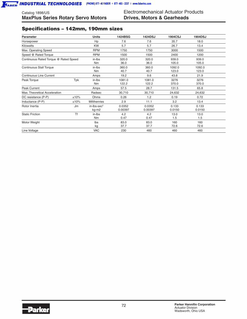
72 Parker Hannifin CorporationActuator DivisionWadsworth, Ohio USA
Catalog 1898/US Electromechanical Actuator ProductsDrives, Motors & Gearheads
Specifications – 142mm, 190mm sizesParameter Units 1424BSG 1424DSJ 1904CSJ 1904DSJ
Horsepower Hp 7.6 7.6 35.7 18.0
Kilowatts KW 5.7 5.7 26.7 13.4
Max. Operating Speed RPM 1750 1750 3000 1500
Speed @ Rated Torque RPM 1500 1500 2400 1200
Continuous Rated Torque @ Rated Speed in-lbs 320.0 320.0 939.0 939.0Nm 36.0 36.0 105.0 105.0
Continuous Stall Torque in-lbs 360.0 360.0 1092.0 1092.0Nm 40.7 40.7 123.0 123.0
Continuous Line Current Amps 19.2 9.6 43.8 21.9
Peak Torque Tpk in-lbs 1081.0 1081.0 3276 3276Nm 122.2 122.2 370.0 370.0
Peak Current Amps 57.5 28.7 131.5 65.8
Max. Theoretical Acceleration Radsec 30,710 30,710 24,632 24,632
DC resistance (P-P) ±10% Ohms 0.26 1.2 0.19 0.72
Inductance (P-P) ±10% Millihenries 2.9 11.1 3.2 13.4
Rotor Inertia Jm in-lbs-sec2 0.0352 0.0352 0.133 0.133kg-m2 0.00397 0.00397 0.0150 0.0150
Static Friction Tf in-lbs 4.2 4.2 13.0 13.0Nm 0.47 0.47 1.5 1.5
Motor Weight lbs 83.0 83.0 160 160kg 37.7 37.7 72.6 72.6
Line Voltage VAC 230 460 460 460
MaxPlus Series Rotary Servo Motors

73 Parker Hannifin CorporationActuator DivisionWadsworth, Ohio USA
Catalog 1898/US Electromechanical Actuator ProductsDrives, Motors & Gearheads
Dri
ves,
Mo
tors
, G
ea
rhe
ad
s
Dri
ves
Gea
rhea
ds
Mo
tors
2.25 SQ.(57.3)
(4x) .218 (5.54) THRUEQ. SP. ON A2.625 (66.68) B.C.
MOTOR LENGTH1.25(31.7)
.063(1.6)
1.500+.000-.002
38.1 +0.00-0.05( )
.3748 +.0000-.0003
9.52 +0.000-0.007( )
MOTOR LENGTH
.680(17.27)
.322(8.17)
.094+.002-.000
2.39 +0.04-0.00( )
.340(8.64)
.750(19.05)
3.04(77.2)
"FO" CONNECTION OPTION
SHAFT OPTIONS
FLAT KEYWAY
BE Series
Size 23
Motor LengthModel Standard FO Option Brake
BE230 3.15 (80) 2.50 (93) 4.51 (115)
BE231 3.65 (93) 3.00 (77) 5.01 (127)
BE232 4.65 (118) 4.00 (102) 6.01 (153)
BE233 5.65 (143) 5.00 (128) 7.01 (178)
Motor LengthModel Standard FO Option Brake
BE341 4.42 (112) 3.65 (93) 5.65 (144)
BE342 5.42 (138) 4.65 (118) 6.65 (169)
BE343 6.42 (163) 5.65 (144) 7.65 (194)
BE344 7.42 (188) 6.65 (169) 8.65 (220)
Size 34
3.35 SQ.(85.1)
(4x) .218 (5.54) THRUEQ. SP. ON A3.875 (98.43) B.C.
1.19(30.2)
MOTOR LENGTH
0.093(2.36)
3.89(98.8)
MOTOR LENGTH
“FO” CONNECTION OPTIONKEYWAYFLAT
SHAFT OPTIONS
0.473(12.01)
1.000(25.4)
0.430(10.92)
1.000(25.4)
0.125+0.002-0.000
3.18+0.05-0.00( )
2.875+0.000-0.002
0.5000+0.0000-0.0005
73.03+0.00-0.05( )
12.7+0.000-0.012( )
Dimensions in inches (mm)
"K" Shaft option is required for ETR mounting.
"K" Shaft option is required for ETR mounting.
Motor Dimensions
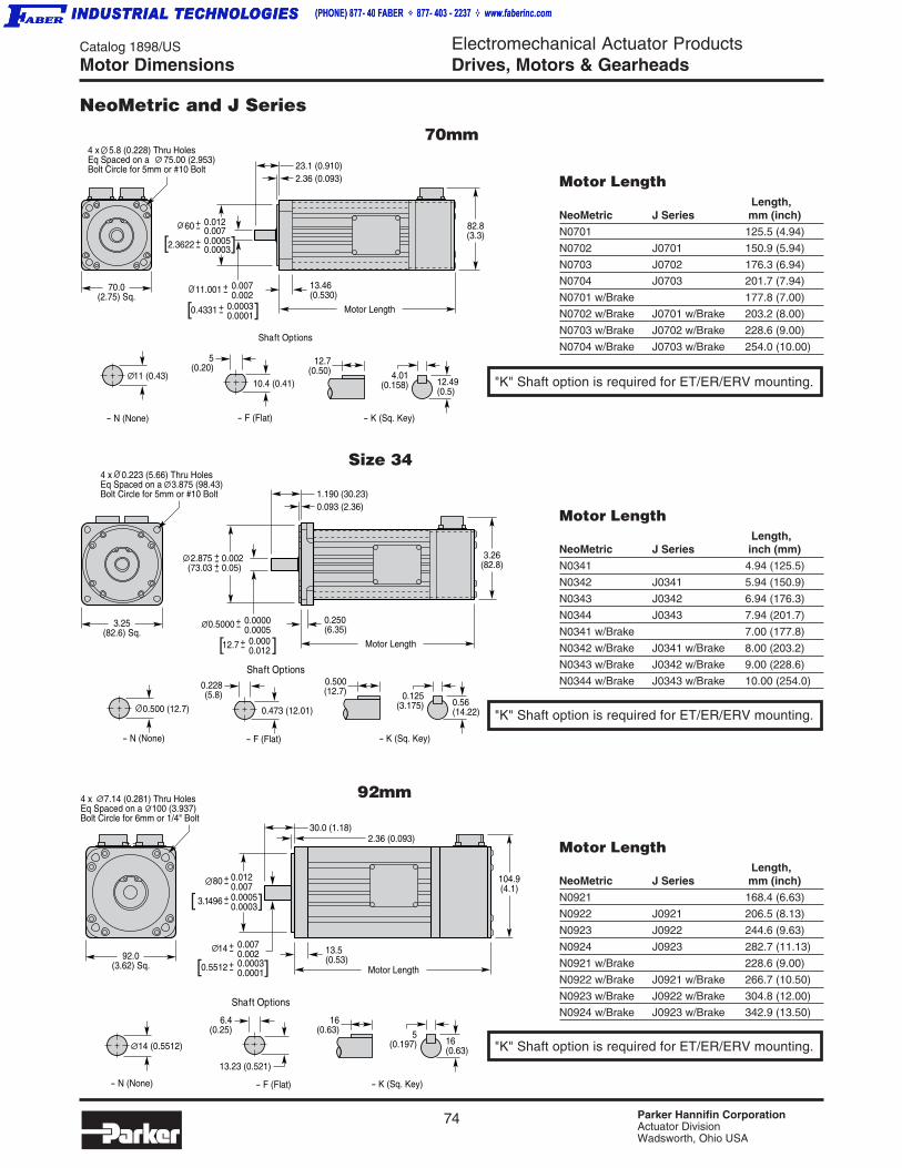
74 Parker Hannifin CorporationActuator DivisionWadsworth, Ohio USA
Catalog 1898/US Electromechanical Actuator ProductsDrives, Motors & Gearheads
Shaft Options
0.473 (12.01) 0.500 (12.7)
- N (None) - F (Flat) - K (Sq. Key)
0.56(14.22)
0.228(5.8)
0.500(12.7) 0.125
(3.175)
0.5000 +-0.00000.0005
12.7 +-0.0000.012
0.250(6.35)
Motor Length
3.26(82.8)
4 x 0.223 (5.66) Thru HolesEq Spaced on a 3.875 (98.43)Bolt Circle for 5mm or #10 Bolt
3.25(82.6) Sq.
1.190 (30.23)0.093 (2.36)
2.875(73.03
0.0020.05)
+-+-
[ ]
0.4331 +-0.00030.0001
11.001 +-0.0070.002
70.0(2.75) Sq.
Shaft Options
10.4 (0.41)
- N (None) - F (Flat)
11 (0.43)
- K (Sq. Key)
12.49(0.5)
5(0.20)
12.7(0.50) 4.01
(0.158)
13.46(0.530)
Motor Length
82.8(3.3)
2.3622 +-0.00050.0003
60 +-0.0120.007
23.1 (0.910)2.36 (0.093)
4 x 5.8 (0.228) Thru HolesEq Spaced on a 75.00 (2.953)Bolt Circle for 5mm or #10 Bolt
[ ]
[ ]
92.0(3.62) Sq.
4 x 7.14 (0.281) Thru HolesEq Spaced on a 100 (3.937)Bolt Circle for 6mm or 1/4" Bolt
104.9(4.1)
13.5(0.53)
Motor Length
30.0 (1.18)2.36 (0.093)
0.5512 +-0.00030.0001
14 +-0.0070.002
3.1496 +-0.00050.0003
80 +-0.0120.007
Shaft Options
14 (0.5512)
- N (None) - F (Flat) - K (Sq. Key)
16(0.63)
6.4(0.25)
16(0.63) 5
(0.197)
13.23 (0.521)
[ ]
[ ]
NeoMetric and J Series
70mm
Size 34
92mm
Motor Length Length,
NeoMetric J Series mm (inch)
N0701 125.5 (4.94)
N0702 J0701 150.9 (5.94)
N0703 J0702 176.3 (6.94)
N0704 J0703 201.7 (7.94)
N0701 w/Brake 177.8 (7.00)
N0702 w/Brake J0701 w/Brake 203.2 (8.00)
N0703 w/Brake J0702 w/Brake 228.6 (9.00)
N0704 w/Brake J0703 w/Brake 254.0 (10.00)
Motor Length Length,
NeoMetric J Series inch (mm)
N0341 4.94 (125.5)
N0342 J0341 5.94 (150.9)
N0343 J0342 6.94 (176.3)
N0344 J0343 7.94 (201.7)
N0341 w/Brake 7.00 (177.8)
N0342 w/Brake J0341 w/Brake 8.00 (203.2)
N0343 w/Brake J0342 w/Brake 9.00 (228.6)
N0344 w/Brake J0343 w/Brake 10.00 (254.0)
Motor Length Length,
NeoMetric J Series mm (inch)
N0921 168.4 (6.63)
N0922 J0921 206.5 (8.13)
N0923 J0922 244.6 (9.63)
N0924 J0923 282.7 (11.13)
N0921 w/Brake 228.6 (9.00)
N0922 w/Brake J0921 w/Brake 266.7 (10.50)
N0923 w/Brake J0922 w/Brake 304.8 (12.00)
N0924 w/Brake J0923 w/Brake 342.9 (13.50)
"K" Shaft option is required for ET/ER/ERV mounting.
"K" Shaft option is required for ET/ER/ERV mounting.
"K" Shaft option is required for ET/ER/ERV mounting.
Motor Dimensions

75 Parker Hannifin CorporationActuator DivisionWadsworth, Ohio USA
Catalog 1898/US Electromechanical Actuator ProductsDrives, Motors & Gearheads
Dri
ves,
Mo
tors
, G
ea
rhe
ad
s
Dri
ves
Gea
rhea
ds
Mo
tors
SMN Series
Motor Dimensions
LM / LB / LE / LBE
S
L
D
SFIM
QF
CF
DF
G
t1h
b
Ø D
V x Z
i
107,4
64,5
40
112
82
8240
82
6232
LE / LBE
SMN0602 with Sin/Cos EncoderOption - 5D
Motor Length Brake Sin/Cos Encoder (SD)
LM – –
LB –
LBE –
LE
Flange
Motor LM / LB / LE / LBE SF IM Type DF F DxL bxhxi t1 V x Z QF C x S G
SMN0602 129.5 / 161.0 / 163.0 / 209 7 40 5 6 75 11x23 4x4x18 12.5 M4x10 70 ∅60 h6x2.5 90
SMN0822 163.5 / 206.5 / 183.5 / 226.5 10 40 8 6.5 100 14x30 5x5x25 16 M5x12.5 82 ∅80 h6x3.5 112
SMN1002 191.5 / 238.5 / 211.5 / 258.5 10 40 5 9 115 19x40 6x6x30 21.5 M6x16 100 ∅95 h6x3.5 135
SMN1152 220 / 265 / 220 / 265 10 41.5 7 11 130 24x50 8x7x40 27 M8x19 130 ∅110 h6x3.5 156
SMN1422 243 / 293 / 243 / 293 12 41.5 5 11 165 24x50 8x7x40 27 M8x19 142 ∅130 h6x11 192.5
Dimensions in mm

76 Parker Hannifin CorporationActuator DivisionWadsworth, Ohio USA
Catalog 1898/US Electromechanical Actuator ProductsDrives, Motors & GearheadsMotor Dimensions
Power ConnectorMS3102A16S-1P
Feedback ConnectorMS3112E14-15P
3.250(82.6)
1.250(31.8)
2.6600(67.56)
3.843(97.6)
OAL
0.394(10) 1.575
(40)
0.138(3.5)
0.472(12)
∅0.748(19)
∅4.528(115)
∅0.374(9.5)
∅3.740(95)
5.512(140)
4.134(105)
.236(6)
Power ConnectorM145: M3102A20-15P
Feedback ConnectorMS3112E14-15P
7.874(200)
∅6.496(165)
5.709(145)
0.315(8)
∅0.453(11.5)
∅0.945(24)
∅5.118(130)
0.590(15)
4.330(110)
3.2505(82.56)
0.138(3.5)
1.969(50)
0.472 (12)
OAL
Terminal Box Only onModels 2053 and 2054
DBack Connector: MS3112E14-15PPower Connector: MS3102A24-10Pon Model M2052 only
2.670(67.8)
0.709(18)
0.158 (4)
3.150(80)
0.850(21.6)
∅1.496(38)
8.071(205)
∅8.465(215)
5.770(146.6) 4.4300
(112.52)
OAL UNLESS OTHERWISE SPECIFIED.X ±0.03 ANGLES ±1°
∅0.551(14)
∅7.086(180)
0.394(10)
9.843(250)
M Series
105mm Frame
145mm Frame
205mm Frame
Motor Length Model Length
M1053 10.75 (273.0)M1054 12.48 (317.0)
Dimensions in inch (mm)
Motor Length Model Length
M1453 11.50 (292.0)M1454 13.94 (354.0)M1455 16.38 (416.0)
Motor Length Model Length
M2052-MS 13.46 (342.0)M2053-PT 16.18 (411.0)M2054-PT 18.90 (480.1)
"K" Shaft option is requiredfor ETR mounting.

77 Parker Hannifin CorporationActuator DivisionWadsworth, Ohio USA
Catalog 1898/US Electromechanical Actuator ProductsDrives, Motors & Gearheads
Dri
ves,
Mo
tors
, G
ea
rhe
ad
s
Dri
ves
Gea
rhea
ds
Mo
tors
Motor Dimensions
MaxPlus Series
A(.004)0.10
A(.004)0.10
(.002)
0.05A
PT02E-14-18P(027)MATING CONNECTOR:
PT06E-14-18S(476)
∅11.00 (.433) THRU (4) EQ SPDAS SHOWN ON ∅165.00 (6.496) B.C.
44.1(1.74)
SG3102E-22-22P(027)MATING CONNECTOR:SG3106E-22-22S(476)
26.90(1.059)
130.00 (5.118)129.97 (5.117)∅
142.0 (5.59)
31.999 (1.2598)31.986 (1.2593)∅
10.000 (.3937)9.964 (.3923)
37.0 Min(1.46)
3.6(1.4)
18.0 (.71)
50.5 (1.99)49.5 (1.95)
492.5 (19.39) Max
95 (3.7) Max
A(.004)0.10
(0.05).002
A(.004)0.10
A
PT02E-14-18P(027)MATING CONNECTOR:
PT06E-14-18S(476)
103.9(4.09)45.5(1.79)
∅14.00 (.551) THRU (4) EQ SPDAS SHOWN ON ∅215.00 (8.464) B.C.
42.39(1.669)
190.0(7.48)
180.01 (7.087)179.99 (7.086)∅
39.9 (1.54) Min
58.5 (2.30)57.5 (2.26)
4.0(0.16) 25.4 (1.00)
549.9 (21.65) Max
123.0 (4.84)
SG3102E-32-17P(027)MATING CONNECTOR:SG3106E-32-17S(476)
14.000 (.5512)13.957 (.5495)
48.019 (1.8905)47.998 (1.8897)∅
393.7 (15.50)
142mm Frame
190mm Frame

78 Parker Hannifin CorporationActuator DivisionWadsworth, Ohio USA
Catalog 1898/US Electromechanical Actuator ProductsDrives, Motors & GearheadsPrecision Gearheads
Precision Honed GearingThe planet gears found in Parker Precision Gearheads are fine-hobbed, casehardened, and precision honed to provide exceptional performance withsignificantly reduced noise generation. They offer balanced axial force operation(not found in helical gear systems) and can run at higher speeds (10,000rpm)with extremely long life needed for servomotor performance requirements.• Honed to AGMA class 12
• Quiet running
• Higher Load capacity
• Increased gear efficiency - higher input speeds
• Consistent backlash (will not degrade over time)
• No lubricant contamination from wear-in particles
• Long maintenance-free life (rated over 20,000 hours)
Quality, Performance, ReliabilityParker Precision Gearheads are planetary gear reducers designed to excel in today’s demanding servo motorapplications. They offer a vast array of selectable options to satisfy nearly every application possibility. Theseinclude in-line or right-angle styles; precision or economy performance grades; and a large selection of motormounts, frame sizes, gear ratios, and shaft sizes. A superior robust design and intrinsic quality ensuredependable performance and long term reliability for high throughput requirements and precision applications.
Superior Bearing DesignAll rotating components are fully supported by robust rolling elementbearings to assure a long lifetime of reliable performance. The planetgears ride on needle roller bearings with increasing number ofneedles for higher load capacities. The output shaft is supported by“zero clearance” matched angular contact bearings. Radial ballbearings, selected for high input speeds, support the sun gear, protectthe servo motor bearing and enable simplified assembly.• High radial (12,000N) and axial (28,000N) load capacity
• Pre-loaded angular contact bearings on the output shaft
• Heavy duty needle bearings support planet gear
• Sun gear ball bearings protect servo motor bearings and permit highinput speeds (up to 10,000rpm)
Patented “Fast - Lock” Pinion Shaft ClampingParker Precision Gearheads offer a patented (US6413006131) motor shaft-to-pinion shaft clamping design which features multiple axial compression slots toprovide an absolute 100% shaft lock. The pinion shaft is fully supported by ballbearings so that no pinion load is exerted on the motor bearings. Shaftselections are offered for a large variety of motor shaft sizes for fast and easymotor installation.• Simplified mounting - only one clamp fastener
• Even compression distribution
• Increased transmittable torque
• Increased clamping safety
• Fully supported fixed pinion shaft
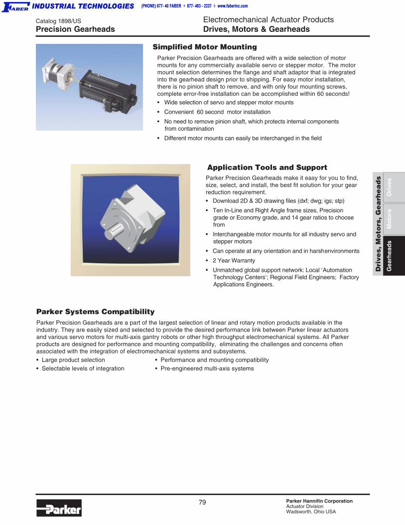
79 Parker Hannifin CorporationActuator DivisionWadsworth, Ohio USA
Catalog 1898/US Electromechanical Actuator ProductsDrives, Motors & Gearheads
Dri
ves,
Mo
tors
, G
ea
rhe
ad
s
Dri
ves
Gea
rhea
ds
Mo
tors
Precision Gearheads
Application Tools and Support
Parker Systems CompatibilityParker Precision Gearheads are a part of the largest selection of linear and rotary motion products available in theindustry. They are easily sized and selected to provide the desired performance link between Parker linear actuatorsand various servo motors for multi-axis gantry robots or other high throughput electromechanical systems. All Parkerproducts are designed for performance and mounting compatibility, eliminating the challenges and concerns oftenassociated with the integration of electromechanical systems and subsystems.• Large product selection • Performance and mounting compatibility• Selectable levels of integration • Pre-engineered multi-axis systems
Simplified Motor MountingParker Precision Gearheads are offered with a wide selection of motormounts for any commercially available servo or stepper motor. The motormount selection determines the flange and shaft adaptor that is integratedinto the gearhead design prior to shipping. For easy motor installation,there is no pinion shaft to remove, and with only four mounting screws,complete error-free installation can be accomplished within 60 seconds!• Wide selection of servo and stepper motor mounts
• Convenient 60 second motor installation
• No need to remove pinion shaft, which protects internal componentsfrom contamination
• Different motor mounts can easily be interchanged in the field
Parker Precision Gearheads make it easy for you to find,size, select, and install, the best fit solution for your gearreduction requirement.• Download 2D & 3D drawing files (dxf; dwg; igs; stp)
• Ten In-Line and Right Angle frame sizes, Precisiongrade or Economy grade, and 14 gear ratios to choosefrom
• Interchangeable motor mounts for all industry servo andstepper motors
• Can operate at any orientation and in harshenvironments
• 2 Year Warranty
• Unmatched global support network: Local ‘AutomationTechnology Centers’; Regional Field Engineers; FactoryApplications Engineers.
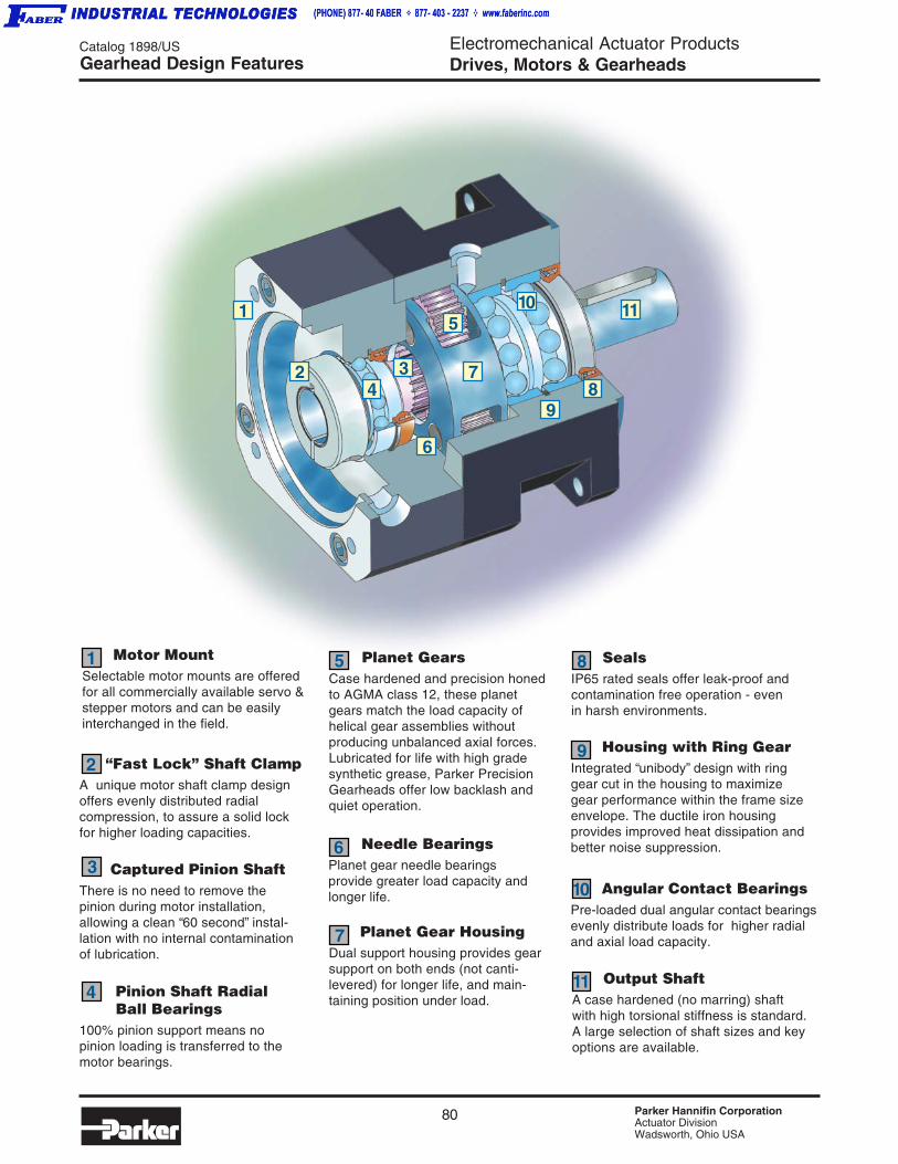
80 Parker Hannifin CorporationActuator DivisionWadsworth, Ohio USA
Catalog 1898/US Electromechanical Actuator ProductsDrives, Motors & GearheadsGearhead Design Features
4
SealsIP65 rated seals offer leak-proof andcontamination free operation - evenin harsh environments.
Housing with Ring GearIntegrated “unibody” design with ringgear cut in the housing to maximizegear performance within the frame sizeenvelope. The ductile iron housingprovides improved heat dissipation andbetter noise suppression.
Pinion Shaft RadialBall Bearings
100% pinion support means nopinion loading is transferred to themotor bearings.
Motor MountSelectable motor mounts are offeredfor all commercially available servo &stepper motors and can be easilyinterchanged in the field.
Needle BearingsPlanet gear needle bearingsprovide greater load capacity andlonger life.
Planet GearsCase hardened and precision honedto AGMA class 12, these planetgears match the load capacity ofhelical gear assemblies withoutproducing unbalanced axial forces.Lubricated for life with high gradesynthetic grease, Parker PrecisionGearheads offer low backlash andquiet operation.
Captured Pinion ShaftThere is no need to remove thepinion during motor installation,allowing a clean “60 second” instal-lation with no internal contaminationof lubrication.
Planet Gear HousingDual support housing provides gearsupport on both ends (not canti-levered) for longer life, and main-taining position under load.
“Fast Lock” Shaft ClampA unique motor shaft clamp designoffers evenly distributed radialcompression, to assure a solid lockfor higher loading capacities.
Angular Contact BearingsPre-loaded dual angular contact bearingsevenly distribute loads for higher radialand axial load capacity.
Output ShaftA case hardened (no marring) shaftwith high torsional stiffness is standard.A large selection of shaft sizes and keyoptions are available.
1
2
3
5
6
7
8
4
9
10
11
1
2
1110
8 9
7
5
3
6
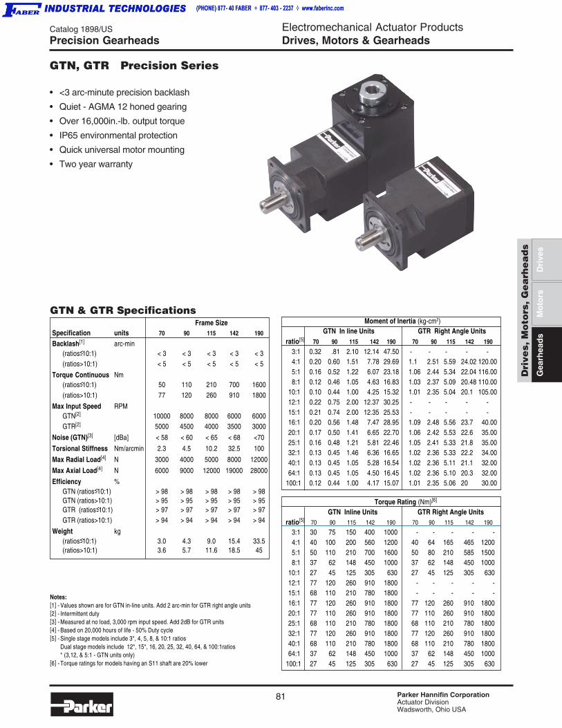
81 Parker Hannifin CorporationActuator DivisionWadsworth, Ohio USA
Catalog 1898/US Electromechanical Actuator ProductsDrives, Motors & Gearheads
Dri
ves,
Mo
tors
, G
ea
rhe
ad
s
Dri
ves
Gea
rhea
ds
Mo
tors
Torque Rating (Nm)[6]
GTN Inline Units GTR Right Angle Unitsratio[5] 70 90 115 142 190 70 90 115 142 190
3:1 30 75 150 400 1000 - - - - -4:1 40 100 200 560 1200 40 64 165 465 12005:1 50 110 210 700 1600 50 80 210 585 15008:1 37 62 148 450 1000 37 62 148 450 1000
10:1 27 45 125 305 630 27 45 125 305 63012:1 77 120 260 910 1800 - - - - -15:1 68 110 210 780 1800 - - - - -16:1 77 120 260 910 1800 77 120 260 910 180020:1 77 110 260 910 1800 77 110 260 910 180025:1 68 110 210 780 1800 68 110 210 780 180032:1 77 120 260 910 1800 77 120 260 910 180040:1 68 110 210 780 1800 68 110 210 780 180064:1 37 62 148 450 1000 37 62 148 450 1000
100:1 27 45 125 305 630 27 45 125 305 630
ratio[5] 70 90 115 142 190 70 90 115 142 190
3:1 0.32 .81 2.10 12.14 47.50 - - - - -4:1 0.20 0.60 1.51 7.78 29.69 1.1 2.51 5.59 24.02 120.005:1 0.16 0.52 1.22 6.07 23.18 1.06 2.44 5.34 22.04 116.008:1 0.12 0.46 1.05 4.63 16.83 1.03 2.37 5.09 20.48 110.00
10:1 0.10 0.44 1.00 4.25 15.32 1.01 2.35 5.04 20.1 105.0012:1 0.22 0.75 2.00 12.37 30.25 - - - - -15:1 0.21 0.74 2.00 12.35 25.53 - - - - -16:1 0.20 0.56 1.48 7.47 28.95 1.09 2.48 5.56 23.7 40.0020:1 0.17 0.50 1.41 6.65 22.70 1.06 2.42 5.53 22.6 35.0025:1 0.16 0.48 1.21 5.81 22.46 1.05 2.41 5.33 21.8 35.0032:1 0.13 0.45 1.46 6.36 16.65 1.02 2.36 5.33 22.2 34.0040:1 0.13 0.45 1.05 5.28 16.54 1.02 2.36 5.11 21.1 32.0064:1 0.13 0.45 1.05 4.50 16.45 1.02 2.36 5.10 20.3 32.00
100:1 0.12 0.44 1.00 4.17 15.07 1.01 2.35 5.06 20 30.00
Frame SizeSpecification units 70 90 115 142 190
Backlash[1] arc-min(ratios<- 10:1) < 3 < 3 < 3 < 3 < 3(ratios>10:1) < 5 < 5 < 5 < 5 < 5
Torque Continuous Nm(ratios<- 10:1) 50 110 210 700 1600(ratios>10:1) 77 120 260 910 1800
Max Input Speed RPMGTN[2] 10000 8000 8000 6000 6000GTR[2] 5000 4500 4000 3500 3000
Noise (GTN)[3] [dBa] < 58 < 60 < 65 < 68 <70
Torsional Stiffness Nm/arcmin 2.3 4.5 10.2 32.5 100
Max Radial Load[4] N 3000 4000 5000 8000 12000
Max Axial Load[4] N 6000 9000 12000 19000 28000
Efficiency %GTN (ratios<- 10:1) > 98 > 98 > 98 > 98 > 98GTN (ratios>10:1) > 95 > 95 > 95 > 95 > 95GTR (ratios<- 10:1) > 97 > 97 > 97 > 97 > 97GTR (ratios>10:1) > 94 > 94 > 94 > 94 > 94
Weight kg(ratios<- 10:1) 3.0 4.3 9.0 15.4 33.5(ratios>10:1) 3.6 5.7 11.6 18.5 45
Precision Gearheads
GTN, GTR Precision Series
Notes:[1] - Values shown are for GTN in-line units. Add 2 arc-min for GTR right angle units[2] - Intermittent duty[3] - Measured at no load, 3,000 rpm input speed. Add 2dB for GTR units[4] - Based on 20,000 hours of life - 50% Duty cycle[5] - Single stage models include 3*, 4, 5, 8, & 10:1 ratios
Dual stage models include 12*, 15*, 16, 20, 25, 32, 40, 64, & 100:1ratios* (3,12, & 5:1 - GTN units only)
[6] - Torque ratings for models having an S11 shaft are 20% lower
GTN & GTR Specifications Moment of Inertia (kg-cm2)GTN In line Units GTR Right Angle Units
• <3 arc-minute precision backlash
• Quiet - AGMA 12 honed gearing
• Over 16,000in.-lb. output torque
• IP65 environmental protection
• Quick universal motor mounting
• Two year warranty
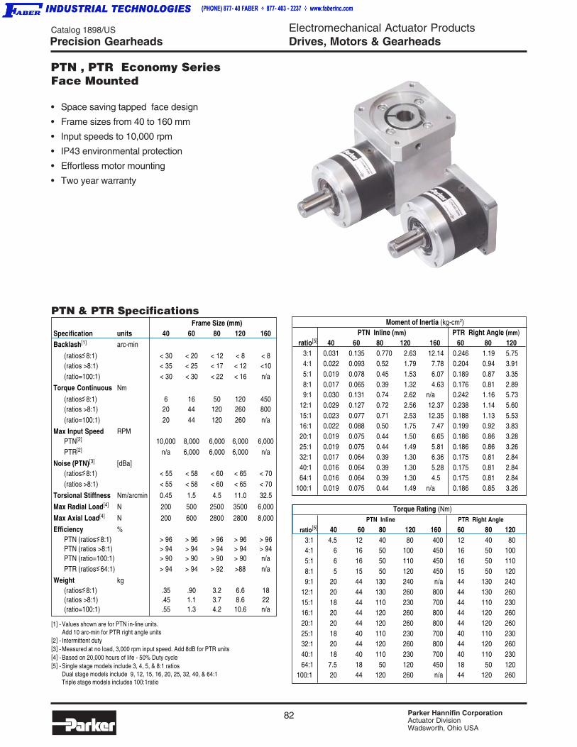
82 Parker Hannifin CorporationActuator DivisionWadsworth, Ohio USA
Catalog 1898/US Electromechanical Actuator ProductsDrives, Motors & Gearheads
Torque Rating (Nm) PTN Inline PTR Right Angle
ratio[5] 40 60 80 120 160 60 80 1203:1 4.5 12 40 80 400 12 40 804:1 6 16 50 100 450 16 50 1005:1 6 16 50 110 450 16 50 1108:1 5 15 50 120 450 15 50 1209:1 20 44 130 240 n/a 44 130 240
12:1 20 44 130 260 800 44 130 26015:1 18 44 110 230 700 44 110 23016:1 20 44 120 260 800 44 120 26020:1 20 44 120 260 800 44 120 26025:1 18 40 110 230 700 40 110 23032:1 20 44 120 260 800 44 120 26040:1 18 40 110 230 700 40 110 23064:1 7.5 18 50 120 450 18 50 120
100:1 20 44 120 260 n/a 44 120 260
Moment of Inertia (kg-cm2) PTN Inline (mm) PTR Right Angle (mm)
ratio[5] 40 60 80 120 160 60 80 1203:1 0.031 0.135 0.770 2.63 12.14 0.246 1.19 5.754:1 0.022 0.093 0.52 1.79 7.78 0.204 0.94 3.915:1 0.019 0.078 0.45 1.53 6.07 0.189 0.87 3.358:1 0.017 0.065 0.39 1.32 4.63 0.176 0.81 2.899:1 0.030 0.131 0.74 2.62 n/a 0.242 1.16 5.73
12:1 0.029 0.127 0.72 2.56 12.37 0.238 1.14 5.6015:1 0.023 0.077 0.71 2.53 12.35 0.188 1.13 5.5316:1 0.022 0.088 0.50 1.75 7.47 0.199 0.92 3.8320:1 0.019 0.075 0.44 1.50 6.65 0.186 0.86 3.2825:1 0.019 0.075 0.44 1.49 5.81 0.186 0.86 3.2632:1 0.017 0.064 0.39 1.30 6.36 0.175 0.81 2.8440:1 0.016 0.064 0.39 1.30 5.28 0.175 0.81 2.8464:1 0.016 0.064 0.39 1.30 4.5 0.175 0.81 2.84
100:1 0.019 0.075 0.44 1.49 n/a 0.186 0.85 3.26
Frame Size (mm)Specification units 40 60 80 120 160Backlash[1] arc-min
(ratios<- 8:1) < 30 < 20 < 12 < 8 < 8(ratios >8:1) < 35 < 25 < 17 < 12 <10(ratio=100:1) < 30 < 30 < 22 < 16 n/a
Torque Continuous Nm
(ratios<- 8:1) 6 16 50 120 450(ratios >8:1) 20 44 120 260 800(ratio=100:1) 20 44 120 260 n/a
Max Input Speed RPMPTN[2] 10,000 8,000 6,000 6,000 6,000PTR[2] n/a 6,000 6,000 6,000 n/a
Noise (PTN)[3] [dBa](ratios<- 8:1) < 55 < 58 < 60 < 65 < 70(ratios >8:1) < 55 < 58 < 60 < 65 < 70
Torsional Stiffness Nm/arcmin 0.45 1.5 4.5 11.0 32.5
Max Radial Load[4] N 200 500 2500 3500 6,000
Max Axial Load[4] N 200 600 2800 2800 8,000
Efficiency %PTN (ratios<- 8:1) > 96 > 96 > 96 > 96 > 96PTN (ratios >8:1) > 94 > 94 > 94 > 94 > 94PTN (ratio=100:1) > 90 > 90 > 90 > 90 n/aPTR (ratios<- 64:1) > 94 > 94 > 92 >88 n/a
Weight kg(ratios<- 8:1) .35 .90 3.2 6.6 18(ratios >8:1) .45 1.1 3.7 8.6 22(ratio=100:1) .55 1.3 4.2 10.6 n/a
Precision Gearheads
• Space saving tapped face design
• Frame sizes from 40 to 160 mm
• Input speeds to 10,000 rpm
• IP43 environmental protection
• Effortless motor mounting
• Two year warranty
PTN , PTR Economy SeriesFace Mounted
PTN & PTR Specifications
[1] - Values shown are for PTN in-line units.Add 10 arc-min for PTR right angle units
[2] - Intermittent duty[3] - Measured at no load, 3,000 rpm input speed. Add 8dB for PTR units[4] - Based on 20,000 hours of life - 50% Duty cycle[5] - Single stage models include 3, 4, 5, & 8:1 ratios
Dual stage models include 9, 12, 15, 16, 20, 25, 32, 40, & 64:1Triple stage models includes 100:1ratio
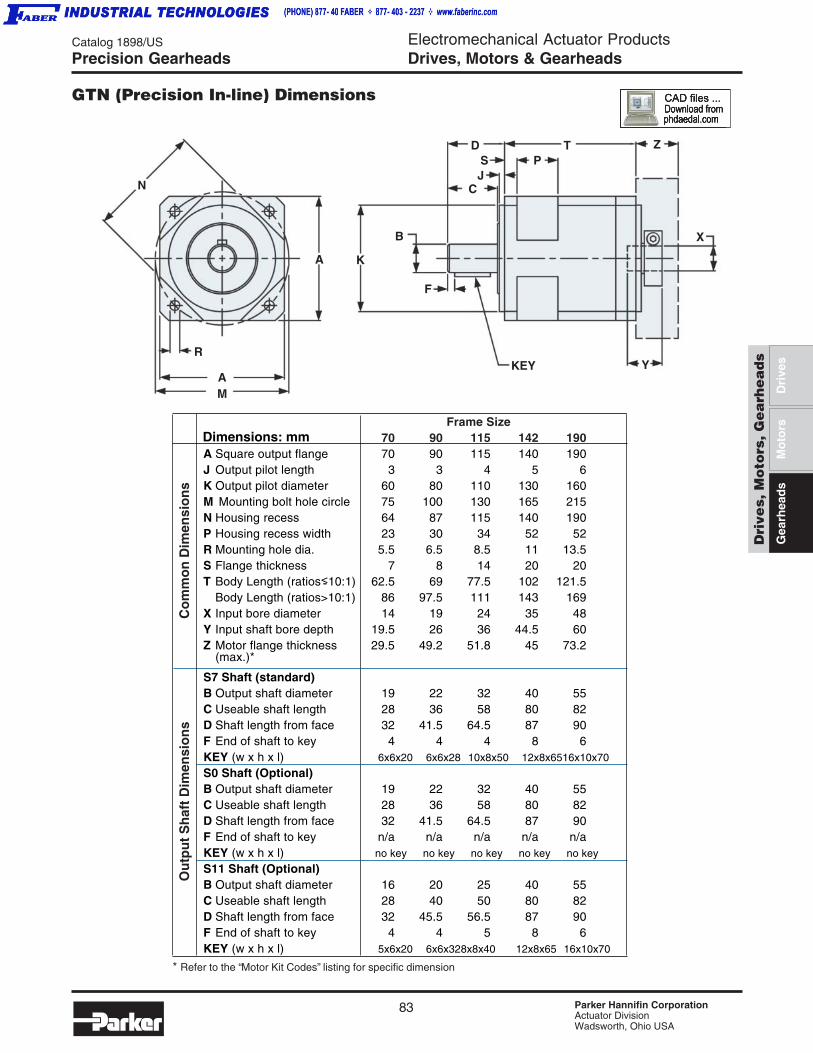
83 Parker Hannifin CorporationActuator DivisionWadsworth, Ohio USA
Catalog 1898/US Electromechanical Actuator ProductsDrives, Motors & Gearheads
Dri
ves,
Mo
tors
, G
ea
rhe
ad
s
Dri
ves
Gea
rhea
ds
Mo
tors Frame Size
70 90 115 142 190A Square output flange 70 90 115 140 190J Output pilot length 3 3 4 5 6K Output pilot diameter 60 80 110 130 160M Mounting bolt hole circle 75 100 130 165 215N Housing recess 64 87 115 140 190P Housing recess width 23 30 34 52 52R Mounting hole dia. 5.5 6.5 8.5 11 13.5S Flange thickness 7 8 14 20 20T Body Length (ratios<- 10:1) 62.5 69 77.5 102 121.5
Body Length (ratios>10:1) 86 97.5 111 143 169X Input bore diameter 14 19 24 35 48Y Input shaft bore depth 19.5 26 36 44.5 60Z Motor flange thickness 29.5 49.2 51.8 45 73.2
(max.)*
S7 Shaft (standard)B Output shaft diameter 19 22 32 40 55C Useable shaft length 28 36 58 80 82D Shaft length from face 32 41.5 64.5 87 90F End of shaft to key 4 4 4 8 6KEY (w x h x l) 6x6x20 6x6x28 10x8x50 12x8x6516x10x70
S0 Shaft (Optional)B Output shaft diameter 19 22 32 40 55C Useable shaft length 28 36 58 80 82D Shaft length from face 32 41.5 64.5 87 90F End of shaft to key n/a n/a n/a n/a n/aKEY (w x h x l) no key no key no key no key no key
S11 Shaft (Optional)B Output shaft diameter 16 20 25 40 55C Useable shaft length 28 40 50 80 82D Shaft length from face 32 45.5 56.5 87 90F End of shaft to key 4 4 5 8 6KEY (w x h x l) 5x6x20 6x6x328x8x40 12x8x65 16x10x70
Precision Gearheads
GTN (Precision In-line) Dimensions
Co
mm
on
Dim
ensi
on
sO
utp
ut
Sh
aft
Dim
ensi
on
sN
B
C
DSJ
PT Z
X
Y
F
KEY
KA
AM
R
* Refer to the “Motor Kit Codes” listing for specific dimension
Dimensions: mm

84 Parker Hannifin CorporationActuator DivisionWadsworth, Ohio USA
Catalog 1898/US Electromechanical Actuator ProductsDrives, Motors & Gearheads
Frame Size70 90 115 142 190
A Square output flange 70 90 115 140 190J Output pilot length 3 3 4 5 6K Output pilot diameter 60 80 110 130 160M Mounting bolt hole circle 75 100 130 165 215N Housing recess 64 87 115 140 190P Housing recess width 23 30 34 52 52R Mounting hole dia. 5.5 6.5 8.5 11 13.5S Flange thickness 7 8 14 20 20T Body Length (ratios<- 10:1) 132 159 192.5 250 321
Body Length (ratios>10:1) 156 187.5 226 291 359V Overall Height 128 156 190 225 308W (ratios<- 10:1) 62.5 69 77.5 110 131
(ratios>10:1) 86 97.5 111 151 169X Input bore diameter 14 19 24 35 48Y Input shaft bore depth 19.5 26 33 60 44.5Z Motor flange (max.)* 29.5 49.2 51.8 45 73.2
S7 Shaft (standard)B Output shaft diameter 19 22 32 40 55C Useable shaft length 28 36 58 80 82D Shaft length from face 32 41.5 64.5 87 90F End of shaft to key 4 4 4 8 6KEY (w x h x l) 6x6x20 6x6x28 10x8x50 12x8x65 16x10x70S0 Shaft (Optional)B Output shaft diameter 19 22 32 40 55C Useable shaft length 28 36 58 80 82D Shaft length from face 32 41.5 64.5 87 90F End of shaft to key n/a n/a n/a n/a n/aKEY (w x h x l) no key no key no key no key no keyS11 Shaft (Optional)B Output shaft diameter 16 20 25 40 55C Useable shaft length 28 40 50 80 82D Shaft length from face 32 45.5 56.5 87 90F End of shaft to key 4 4 5 8 6KEY (w x h x l) 5x6x20 6x6x32 8x8x40 12x8x65 16x10x70
Precision Gearheads
GTR (Precision Right Angle) Dimensions
N
MA
A K
CJS
DP
Y
B
F
KEYT
V
Z
X
R
motor mounting flange
Co
mm
on
Dim
ensi
on
sO
utp
ut
Sh
aft
Dim
ensi
on
s
* Refer to the “Motor Kit Codes” listing for specific dimension
W
Dimensions: mm
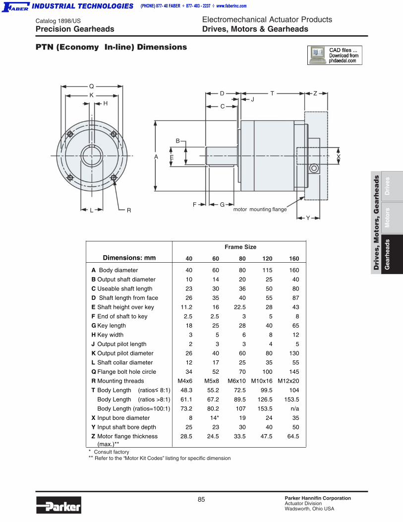
85 Parker Hannifin CorporationActuator DivisionWadsworth, Ohio USA
Catalog 1898/US Electromechanical Actuator ProductsDrives, Motors & Gearheads
Dri
ves,
Mo
tors
, G
ea
rhe
ad
s
Dri
ves
Gea
rhea
ds
Mo
tors
Precision Gearheads
Frame Size
40 60 80 120 160
A Body diameter 40 60 80 115 160
B Output shaft diameter 10 14 20 25 40
C Useable shaft length 23 30 36 50 80
D Shaft length from face 26 35 40 55 87
E Shaft height over key 11.2 16 22.5 28 43
F End of shaft to key 2.5 2.5 3 5 8
G Key length 18 25 28 40 65
H Key width 3 5 6 8 12
J Output pilot length 2 3 3 4 5
K Output pilot diameter 26 40 60 80 130
L Shaft collar diameter 12 17 25 35 55
Q Flange bolt hole circle 34 52 70 100 145
R Mounting threads M4x6 M5x8 M6x10 M10x16 M12x20
T Body Length (ratios<- 8:1) 48.3 55.2 72.5 99.5 104
Body Length (ratios >8:1) 61.1 67.2 89.5 126.5 153.5
Body Length (ratios=100:1) 73.2 80.2 107 153.5 n/a
X Input bore diameter 8 14* 19 24 35
Y Input shaft bore depth 25 23 30 40 50
Z Motor flange thickness 28.5 24.5 33.5 47.5 64.5(max.)**
PTN (Economy In-line) Dimensions
Dimensions: mm
* Consult factory** Refer to the “Motor Kit Codes” listing for specific dimension
H
Q
KJ
D T Z
X
Y
GF
E
B
A
L R
C
motor mounting flange

86 Parker Hannifin CorporationActuator DivisionWadsworth, Ohio USA
Catalog 1898/US Electromechanical Actuator ProductsDrives, Motors & Gearheads
Frame Size
60 80 120
A Body diameter 60 80 115
B Output shaft diameter 14 20 25
C Useable shaft length 30 36 50
D Shaft length from face 35 40 55
E Shaft height over key 16 22.5 28
F End of shaft to key 2.5 4 5
G Key length 25 28 40
H Key width 5 6 8
J Output pilot length 3 3 4
K Output pilot diameter 40 60 80
L Output shaft collar diameter 17 25 35
Q Flange bolt hole circle 52 70 100
R Mounting threads M5x8 M6x10 M10x16
T Body Length (ratios<- 8:1) 112.5 144.5 192
Body Length (ratios >8:1) 124.5 161.5 219
Body Length (ratios=100:1) 137.5 179 246
V Overall height 68.5 88.3 123.7
W (ratios <- 8:1) 47 60.5 74
(ratios >8:1) 59 77.5 101
(ratios=100:1) 72 95 128
X Input bore diameter 11 19 24
Y Input shaft bore depth 23 30 40
Z Motor flange thickness 24.5 33.5 47.5(max.)*
PTR - Economy Right Angle
Dimensions: mm
* Refer to the “Motor Kit Codes” listing for specific dimension
WX
T
I EBV
DJ
C
G F
RH
L
Q
K
A
ZY
Precision Gearheads
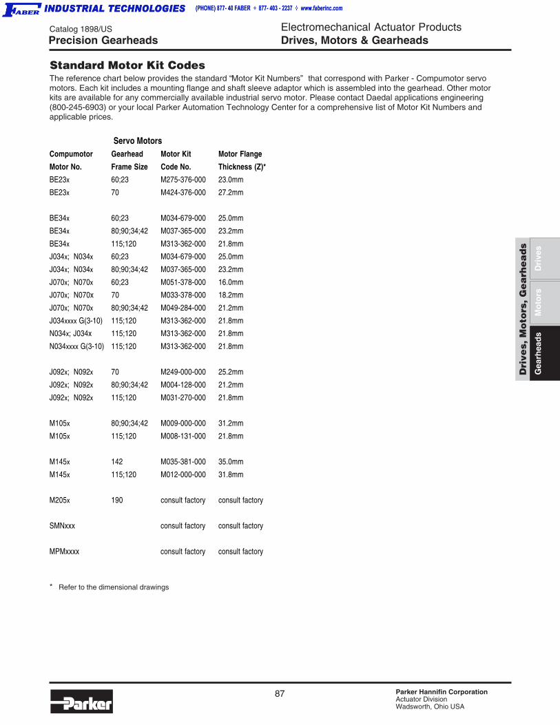
87 Parker Hannifin CorporationActuator DivisionWadsworth, Ohio USA
Catalog 1898/US Electromechanical Actuator ProductsDrives, Motors & Gearheads
Dri
ves,
Mo
tors
, G
ea
rhe
ad
s
Dri
ves
Gea
rhea
ds
Mo
tors
The reference chart below provides the standard “Motor Kit Numbers” that correspond with Parker - Compumotor servomotors. Each kit includes a mounting flange and shaft sleeve adaptor which is assembled into the gearhead. Other motorkits are available for any commercially available industrial servo motor. Please contact Daedal applications engineering(800-245-6903) or your local Parker Automation Technology Center for a comprehensive list of Motor Kit Numbers andapplicable prices.
Servo MotorsCompumotor Gearhead Motor Kit Motor Flange
Motor No. Frame Size Code No. Thickness (Z)*
BE23x 60;23 M275-376-000 23.0mm
BE23x 70 M424-376-000 27.2mm
BE34x 60;23 M034-679-000 25.0mm
BE34x 80;90;34;42 M037-365-000 23.2mm
BE34x 115;120 M313-362-000 21.8mm
J034x; N034x 60;23 M034-679-000 25.0mm
J034x; N034x 80;90;34;42 M037-365-000 23.2mm
J070x; N070x 60;23 M051-378-000 16.0mm
J070x; N070x 70 M033-378-000 18.2mm
J070x; N070x 80;90;34;42 M049-284-000 21.2mm
J034xxxx G(3-10) 115;120 M313-362-000 21.8mm
N034x; J034x 115;120 M313-362-000 21.8mm
N034xxxx G(3-10) 115;120 M313-362-000 21.8mm
J092x; N092x 70 M249-000-000 25.2mm
J092x; N092x 80;90;34;42 M004-128-000 21.2mm
J092x; N092x 115;120 M031-270-000 21.8mm
M105x 80;90;34;42 M009-000-000 31.2mm
M105x 115;120 M008-131-000 21.8mm
M145x 142 M035-381-000 35.0mm
M145x 115;120 M012-000-000 31.8mm
M205x 190 consult factory consult factory
SMNxxx consult factory consult factory
MPMxxxx consult factory consult factory
Standard Motor Kit Codes
* Refer to the dimensional drawings
Precision Gearheads
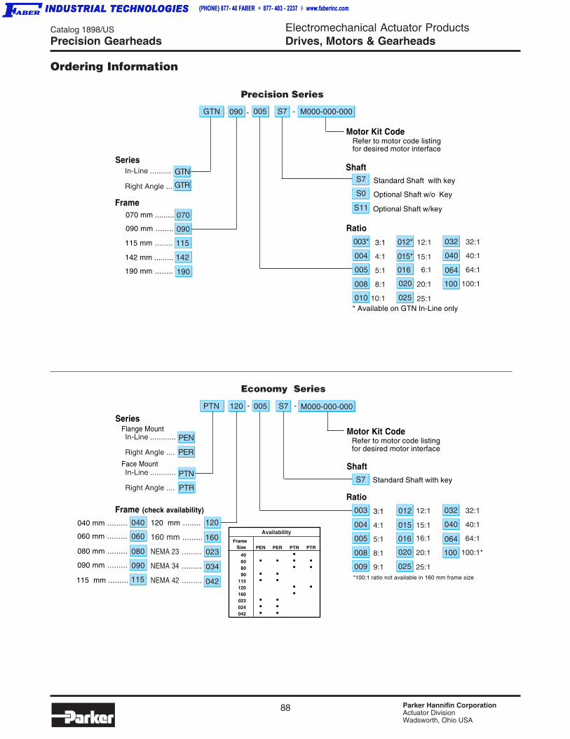
88 Parker Hannifin CorporationActuator DivisionWadsworth, Ohio USA
Catalog 1898/US Electromechanical Actuator ProductsDrives, Motors & Gearheads
3:1
4:1
5:1
8:1
9:1
Ratio
12:1
15:1
16:1
20:1
25:1
32:1
40:1
64:1
100:1*
040
032
064
100020
016
025
012
015
003
005
004
008
009
Precision Series
Economy Series
040 mm .........
090 mm .........
120 mm ........
160 mm .........
NEMA 23 .........
NEMA 34 .........
NEMA 42 .........
060 mm .........
In-Line ..........
Right Angle ...
Frame 070 mm .........
115 mm ........
142 mm .........
190 mm ........
090 mm ........
SeriesGTN
GTR
070
115
090
142
In-Line ............
Right Angle ....
Frame (check availability)
Series
PTN
PTR
040
090
060
120
023
042
S7
ShaftStandard Shaft with key
Motor Kit Code
190
080 mm ......... 080
Availability Frame
Size PEN PER PTN PTR
40 .60 . . . .80 . .90 . .
115 . .120 . .160 .023 . .024 . .042 . .
115 mm ......... 115
In-Line ............
Right Angle ....
PEN
PER
Flange Mount
Face Mount
034
- S7 M000-000-000-GTN 090 005
Refer to motor code listingfor desired motor interface
Motor Kit Code
S7
ShaftStandard Shaft with key
* Available on GTN In-Line only
3:1
4:1
5:1
8:1
10:1
Ratio
12:1
15:1
6:1
20:1
25:1
32:1
40:1
64:1
100:1
040
032
064
100020
016
025
012*
015*
003*
005
004
008
010
S0 Optional Shaft w/o Key
S11 Optional Shaft w/key
160
*100:1 ratio not available in 160 mm frame size
Refer to motor code listingfor desired motor interface
PTN S7 M000-000-000005120 - -
Ordering Information
Precision Gearheads

89 Parker Hannifin CorporationActuator DivisionWadsworth, Ohio USA
Electromechanical Actuator ProductsSensors
Catalog 1898/US
O
Senso
rs
Introduction
Global Drop-InPosition Sensing Sensors
• Both Reed Switch and Solid State Sensor Versions
• Sensors Available World-Wide
• Solid State Sensors use GMR Technology
• 5 Different Connection Styles
• Allow Position Sensing Anywhere Along Cylinder Position
• The Same Sensor is Used On Virtually All Series of Cylinders
• CE Approved
• Defined by Part Number: P8S-G
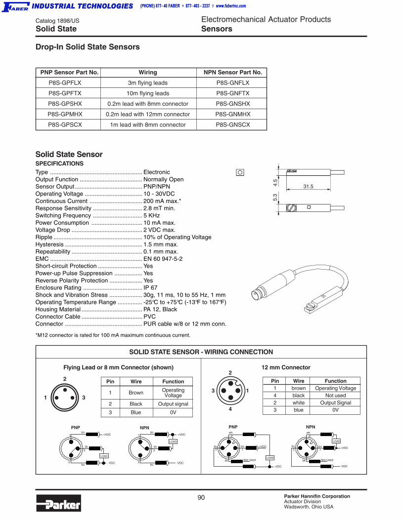
Electromechanical Actuator ProductsSensors
90 Parker Hannifin CorporationActuator DivisionWadsworth, Ohio USA
Catalog 1898/US
OSolid State
Solid State SensorSPECIFICATIONSType ........................................................ ElectronicOutput Function ...................................... Normally OpenSensor Output ......................................... PNP/NPNOperating Voltage ................................... 10 - 30VDCContinuous Current ................................ 200 mA max.*Response Sensitivity .............................. 2.8 mT min.Switching Frequency .............................. 5 KHzPower Consumption ............................... 10 mA max.Voltage Drop ........................................... 2 VDC max.Ripple ...................................................... 10% of Operating VoltageHysteresis ............................................... 1.5 mm max.Repeatability ........................................... 0.1 mm max.EMC ........................................................ EN 60 947-5-2Short-circuit Protection ........................... YesPower-up Pulse Suppression ................. YesReverse Polarity Protection .................... YesEnclosure Rating .................................... IP 67Shock and Vibration Stress .................... 30g, 11 ms, 10 to 55 Hz, 1 mmOperating Temperature Range ............... -25°C to +75°C (-13°F to 167°F)Housing Material ..................................... PA 12, BlackConnector Cable ..................................... PVCConnector ............................................... PUR cable w/8 or 12 mm conn.
*M12 connector is rated for 100 mA maximum continuous current.
12 mm Connector2
4
13
Pin Wire Function1 brown Operating Voltage4 black Not used2 white Output Signal3 blue 0V
Drop-In Solid State Sensors
Flying Lead or 8 mm Connector (shown)
2
1 3
Pin Wire Function
1 Brown OperatingVoltage
2 Black Output signal
3 Blue 0V
SOLID STATE SENSOR - WIRING CONNECTION
PNP NPN
bu bu
bn bn
2 2
3 3
1 1
bk bk
LOAD
LOAD
+VDC +VDC
-VDC -VDC
PNP NPNwh wh
bu bn
2 2
3 1
bk Not UsedLOAD
+VDC
-VDC
bu3
bn1
bk Not Used
+VDC
-VDC
LOAD
PNP Sensor Part No. Wiring NPN Sensor Part No.
P8S-GPFLX 3m flying leads P8S-GNFLX
P8S-GPFTX 10m flying leads P8S-GNFTX
P8S-GPSHX 0.2m lead with 8mm connector P8S-GNSHX
P8S-GPMHX 0.2m lead with 12mm connector P8S-GNMHX
P8S-GPSCX 1m lead with 8mm connector P8S-GNSCX
31.54.5
5.3

91 Parker Hannifin CorporationActuator DivisionWadsworth, Ohio USA
Electromechanical Actuator ProductsSensors
Catalog 1898/US
O
Senso
rs
Reed
Reed SwitchSPECIFICATIONSType ............................................ ReedOutput Function .......................... Normally OpenOperating Voltage ....................... 10 - 120 VAC*
10 - 30 VDCContinuous Current .................... 100 mA max.Response Sensitivity .................. 2.5 mT min.Switching Frequency .................. 400 KzVoltage Drop ............................... 3 V max.Ripple .......................................... 10% of Operating VoltageHysteresis ................................... 1.5 mm max.Repeatability ............................... 0.2 mm max.EMC ............................................ EN 60 947-5-2Reverse Polarity Protection ........ YesEnclosure Rating ........................ IP 67Shock and Vibration Stress ........ 30g, 11 ms, 10 to 55 Hz, 1 mmOperating Temperature Range ... -25°C to +75°C (-13°F to 167°F)Housing Material ......................... PA 12, BlackConnector Cable ......................... PVCConnector ................................... PUR cable w/8 or 12 mm conn.
*8mm connector rated for 75 VAC max.
2
1 3
REED SWITCH - WIRING CONNECTIONFlying Lead or 8 mm Connector
Pin Wire Function
1 Brown OperatingVoltage
2 Black Output signal
3 Blue Not used
12 mm Connector2
4
13
Pin Wire Function
1 Brown OperatingVoltage
2 White Output signal
3 Blue Not used
4 Black Not used
Drop-In Reed Switches
(Recommended for longer life 125 VAC)Put a resistor and capacitor in parallel with the load. Select the resistor and capacitoraccording to the load.
Typical Example:CR: Relay coil (under 2W coil rating)R: Resistor 1 KΩ - 5 KΩ, 1/4 WC: Capacitor 0.1 µF, 600 V
(Required for proper operation 24V DC)
Put Diode parallel to loads following polarity as shown below.
D: Diode: select a Diode with the breakdown voltage and current rating according tothe load.
Typical Example— 100 Volt, 1 Amp DiodeCR: Relay coil (under 0.5W coil rating)
Circuit for Switching Contact Protection (Inductive Loads)
Caution– Use an ampmeter to test reed switch current. Testing devices such as
incandescent light bulbs may subject the reed switch to high in-rush loads.
– NOTE: When checking an unpowered reed switch for continuity with a digitalohmmeter the resistance reading will change from infinity to a very largeresistance (2 M ohm) when the switch is activated. This is due to the presenceof a diode in the reed switch.
– Anti-magnetic shielding is recommended for reed switches exposed to highexternal RF or magnetic fields.
– The magnetic field strength of the piston magnet is designed to operate with ourswitches. Other manufacturers’ switches or sensors may not operate correctly inconjunction with these magnets.
!
LoadBrown
Blue
DC
D
R
Brown
Blue
C
AC
Load
– Use relay coils for reed switch contact protection.
– The operation of some 120 VAC PLC’s (especially some older Allen-BradleyPLC’s) can overload the reed switch. The switch may fail to release after thepiston magnet has passed. This problem may be corrected by the placement of a700 to 1K OHM resistor between the switch and the PLC input terminal. Consultthe manufacturer of the PLC for appropriate circuit.
– Switches with long wire leads (greater than 15 feet) can cause capacitancebuild-up and sticking will result. Attach a resistor in series with the reed switch(the resistor should be installed as close as possible to the switch). The resistorshould be selected such that R (ohms) >E/0.3.
Switch Part No. Wiring
P8S-GRFLX 3m flying leads
P8S-GRFTX 10m flying leads
P8S-GRSHX 0.2m lead with 8mm connector
P8S-GRMHX 0.2m lead with 12mm connector
P8S-GRSCX 1m lead with 8mm connector

Electromechanical Actuator ProductsSensors
92 Parker Hannifin CorporationActuator DivisionWadsworth, Ohio USA
Catalog 1898/US
ONotes

93 Parker Hannifin CorporationActuator DivisionWadsworth, Ohio USA
Electromechanical Actuator ProductsEngineering Reference
Catalog 1898/US
O
Refe
rence
General Information
Densities of Common MaterialsMaterial oz/in3 gm/cm3
Aluminum (cast or hard-drawn) 1.54 2.66
Brass (cast or rolled 60% Cu;40% Zn) 4.80 8.30
Bronze (cast, 90% Cu, 10% Sn) 4.72 8.17
Copper (Cast or hand drawn) 5.15 8.91
Plastic 0.64 1.11
Steel (hot or cold rolled, 0.2 or 0.8% carbon) 4.48 7.75
Hard Wood 0.46 0.80
Soft Wood 0.28 0.48
Most tables give densities in lb-ft3. To convert to oz-in3 dividethis value by 108 and to convert lb/ft3 to gm-cm3 divide by 62.5.The conversion from oz-in3 to gm/cm3 is performed bymultiplying oz-in3 by 1.73.
Mechanism Efficiencies
Acme Screw (brass nut) 0.35
Acme Screw (plastic nut) 0.45
Ball Screw 0.90
Preloaded Ball Screw 0.75
Helical Gear 0.70
Spur Gear 0.60
Timing Belt/Pulley 0.90
Coefficients of FrictionMaterial* µs µk
Steel on Steel 0.80 0.40
Steel on Steel (lubricated) 0.16 0.03
Aluminum on Steel 0.45 0.30
Copper on Steel 0.22 0.22
Brass on Steel 0.35 0.19
Teflon on Steel 0.04 0.04
*dry contact unless noted

Electromechanical Actuator ProductsEngineering Reference
94 Parker Hannifin CorporationActuator DivisionWadsworth, Ohio USA
Catalog 1898/US
O
Force Conversion FactorsMultiply value A by conversion factor in table to calculate value B.
B oz lbf N kg(f)Aoz 1 0.0625 0.2780 0.0284
lbf 16 1 4.4482 0.4536
N 3.5970 0.2248 1 0.1020
kg(f) 35.2740 2.2050 9.8068 1
Torque Conversion FactorsMultiply value A by conversion factor in table to calculate value B.
B oz-in lb-in lb-ft NmAoz-in 1 0.0625 5.2083E-03 7.0616E-03
lb-in 16 1 0.0833 0.1130
lb-ft 192 12 1 1.356
Nm 141.61 8.8507 0.7376 1
Rotational Inertia Conversion FactorsMultiply value A by conversion factor in table to calculate value B.
B oz-in2 oz-in-sec2 lb-in2 lb-in-sec2 lb-ft2 lb-ft-sec2 kg-m2 kg-m-sec2 kg-cm2 kg-cm-sec2
A
oz-in2 1 2.5900E-03 6.2500E-02 1.6190E-04 4.3403E-04 1.3490E-05 1.8290E-05 1.8650E-06 1.8290E-01 1.8650E-04
oz-in-sec2 3.8610E+02 1 2.4130E+01 6.2500E-02 1.6760E-01 5.2080E-03 7.0620E-03 7.2010E-04 7.0620E+01 7.2010E-02
lb-in2 1.6000E+01 4.1442E-02 1 2.5900E-03 6.9444E-03 2.1583E-04 2.9260E-04 2.9840E-05 2.9260E+00 2.9840E-03
lb-in-sec2 6.1767E+03 1.6000E+01 3.8610E+02 1 2.6810E+00 8.3333E-02 1.1300E-01 1.1520E-02 1.1300E+03 1.1520E+00
lb-ft2 2.3040E+03 5.9666E+00 1.4400E+02 3.7300E-01 1 3.1080E-02 4.2140E-02 4.2970E-03 4.2140E+02 4.2970E-01
lb-ft-sec2 7.4129E+04 1.9201E+02 4.6333E+03 1.2000E+01 3.2175E+01 1 1.3560E+00 1.3824E-01 1.3560E+04 1.3824E+01
kg-m2 5.4675E+04 1.4160E+02 3.4176E+03 8.8496E+00 2.3730E+01 7.3746E-01 1 1.0190E-01 1.0000E+04 1.0190E+01
kg-m-sec2 5.3619E+05 1.3887E+03 3.3512E+04 8.6806E+01 2.3272E+02 7.2338E+00 9.8135E+00 1 9.8130E+04 1.0000E+02
kg-cm2 5.4675E+00 1.4160E-02 3.4176E-01 8.8496E-04 2.3730E-03 7.3746E-05 1.0000E-04 1.0191E-05 1 1.0190E-03
kg-cm-sec2 5.3619E+03 1.3887E+01 3.3512E+02 8.6806E-01 2.3272E+00 7.2338E-02 9.8135E-02 1.0000E-02 9.8135E+02 1
Length/Distance Conversion FactorsMultiply value A by conversion factor in table to calculate value B.
B in ft mm cm mAin 1 0.0833 25.4 2.54 0.0254
ft 12 1 304.8 30.48 0.3048
mm 0.03937 0.00328 1 0.1 0.001
cm 0.3937 0.03281 10 1 .01
m 39.37 3.281 1000 100 1
Conversion Factors

95 Parker Hannifin CorporationActuator DivisionWadsworth, Ohio USA
Electromechanical Actuator ProductsEngineering Reference
Catalog 1898/US
O
Refe
rence
Notes
96 Parker Hannifin CorporationActuator DivisionWadsworth, Ohio USA
Offer of Sale
1. Terms and Conditions of Sale: All descriptions, quotations, proposals, offersacknowledgments, acceptances and sales of Seller's products are subject to andshall be governed exclusively by the terms and conditions stated herein. Buyer'sacceptance of any offer to sell is limited to these terms and conditions. Any termsor conditions in addition to, or inconsistent with those stated herein, proposed byBuyer in any acceptance of an offer by Seller, are hereby objected to. No suchadditional, different or inconsistent terms and conditions shall become part of thecontract between, Buyer and Seller unless expressly accepted in writing by Seller.Seller's acceptance of any offer to purchase by Buyer is expressly conditional uponBuyer's assent to all the terms and conditions stated herein, including any termsin addition to, or inconsistent with those contained in Buyer's offer. Acceptance ofSeller's products shall in all events constitute such assent.
2. Payment: Payment shall be made by Buyer net 30 days from the date of deliveryof the items purchased hereunder. Amounts not timely paid shall bear interest atthe maximum rate permitted by law for each month or portion thereof that the Buyeris late in making payment. Any claims by Buyer for omissions or shortages in ashipment shall be waived unless Seller receives notice thereof within 30 days afterBuyer's receipt of the shipment.
3. Delivery: Unless otherwise provided on the face hereof, delivery shall be madeF.O.B. Seller's plant. Regardless of the method of delivery, however, risk of lossshall pass to Buyer upon Seller's delivery to a carrier. Any delivery dates shownare approximate only and Seller shall have no liability for any delays in delivery.
4. Warranty: Seller warrants that the items sold hereunder shall be free fromdefects in material or workmanship for a period of 24 months (18 months forsystems) from date of shipment from Parker Hannifin Corporation. THIS WAR-RANTY COMPRISES THE SOLE AND ENTIRE WARRANTY PERTAINING TOITEMS PROVIDED HEREUNDER. SELLER MAKES NO OTHER WARRANTY,GUARANTEE, OR REPRESENTATION OF ANY KIND WHATSOEVER. ALLOTHER WAR-RANTIES, INCLUDING BUT NOT LIMITED TO, MERCHANT-ABILITY AND FITNESS FOR PURPOSE, WHETHER EXPRESS, IMPLIED, ORARISING BY OPERATION OF LAW, TRADE USAGE, OR COURSE OF DEAL-ING ARE HEREBY DISCLAIMED. NOTWITHSTANDING THE FOREGOING,THERE ARE NO WARRANTIES WHATSOEVER ON ITEMS BUILT OR AC-QUIRED WHOLLY OR PARTIALLY, TO BUYER'S DESIGNS OR SPECIFICA-TIONS.
5. Limitation of Remedy: SELLER'S LIABILITY ARISING FROM OR IN ANYWAY CONNECTED WITH THE ITEMS SOLD OR THIS CONTRACT SHALL BELIMITED EXCLUSIVELY TO REPAIR OR REPLACEMENT OF THE ITEMS SOLDOR REFUND OF THE PURCHASE PRICE PAID BY BUYER, AT SELLER'S SOLEOPTION. IN NO EVENT SHALL SELLER BE LIABLE FOR ANY INCIDENTAL,CONSEQUENTIAL OR SPECIAL DAMAGES OF ANY KIND OR NATURE WHAT-SOEVER, INCLUDING BUT NOT LIMITED TO LOST PROFITS ARISING FROMOR IN ANY WAY CONNECTED WITH THIS AGREEMENT OR ITEMS SOLDHEREUNDER, WHETHER ALLEGED TO ARISE FORM BREACH OF CON-TRACT, EXPRESS OR IMPLIED WARRANTY, OR IN TORT, INCLUDING WITH-OUT LIMITATION, NEGLIGENCE, FAILURE TO WARN OR STRICT LIABILITY.
6. Changes, Reschedules and Cancellations: Buyers may request to modify thedesigns or specifications for the items sold hereunder as well as the quantities anddelivery dates thereof, or may request to cancel all or part of this order, however,no such requested modification or cancellation shall become part of the contractbetween Buyer and Seller unless accepted by Seller in a written amendment to thisAgreement. Acceptance of any such requested modification of cancellation shallbe at Seller's discretion, and shall be upon such terms and conditions as Seller mayrequire.
7. Special Tooling: A tooling charge may be imposed for any special tooling,including without limitation, dies, fixtures, molds and patterns, acquired to manu-facture items sold pursuant to this contract. Such special tooling shall be andremain Seller's property notwithstanding payment of any charges by Buyer. In noevent will Buyer acquire any interest in apparatus belonging to Seller which isutilized in the manufacture of the items sold hereunder, even if such apparatus hasbeen specially converted or adapted for such manufacture and notwithstandingany charges paid by Buyer. Unless otherwise agreed, Seller shall have the rightto alter, discard or otherwise dispose of any special tooling or other property in itssole discretion at any time.
8. Buyer's Property: Any designs, tools, patterns, materials, drawingsconfidential information or equipment furnished by Buyer, or any other itemswhich become Buyer's property, may be considered obsolete and may bedestroyed by Seller after two (2) consecutive years have elapsed withoutBuyer placing an order for the items which are manufactured using suchproperty. Seller shall not be responsible for any loss or damage to suchproperty while it is in Seller's possession or control.
9. Taxes: Unless otherwise indicated on the face hereof, all prices andcharges are exclusive of excise, sales, use, property, occupational or liketaxes which may be imposed by any taxing authority upon the manufacture,sale or delivery of the items sold hereunder. If any such taxes must be paidby Seller or if Seller is liable for the collection of such tax, the amount thereofshall be in addition to the amounts for the items sold. Buyer agrees to pay allsuch taxes or to reimburse Seller therefore upon receipt of its invoice. If Buyerclaims exemption from any sales, use or other tax imposed by any taxingauthority, Buyer shall save Seller harmless from and against any such tax,together with any interest or penalties thereon which may be assessed if theitems are held to be taxable.
10. Indemnity For Infringement of Intellectual Property Rights: Sellershall have no liability for infringement of any patents, trademarks, copyrights,trade dress, trade secrets or similar rights except as provided in this Part 10.Seller will defend and indemnify Buyer against allegations of infringement ofU.S. patents, U.S. trademarks, copyrights, trade dress and trade secrets(hereinafter 'Intellectual Property Rights'). Seller will defend at its expenseand will pay the cost of any settlement or damages awarded in an actionbrought against Buyer based on an allegation that an item sold pursuant tothis contract infringes the Intellectual Property Rights of a third party. Seller'sobligation to defend and indemnify Buyer is contingent on Buyer notifyingSeller within ten (10) days after Buyer becomes aware of such allegations ofinfringement, and Seller having sole control over the defense of any allega-tions or actions including all negotiations for settlement or compromise. If anitem sold hereunder is subject to a claim that it infringes the IntellectualProperty Rights of a third party, Seller may, at its sole expense and option,procure for Buyer the right to continue using said item, replace or modify saiditem so as to make it noninfringing, or offer to accept return of said item andreturn the purchase price less a reasonable allowance for depreciation.Notwithstanding the foregoing, Seller shall have no liability for claims ofinfringement based on information provided by Buyer, or directed to itemsdelivered hereunder for which the designs are specified in whole or part byBuyer, or infringements resulting from the modification, combination or usein a system of any item sold hereunder. The foregoing provisions of this Part10 shall constitute Seller's sole and exclusive liability and Buyer's sole andexclusive remedy for infringement of Intellectual Property Right.
If a claim is based on information provided by Buyer or if the design for an itemdelivered hereunder is specified in whole or in part by Buyer, Buyer shalldefend and indemnify Seller for all costs, expenses or judgements resultingfrom any claim that such item infringes any patent, trademark, copyright,trade dress, trade secret or any similar right.
11. Force Majeure: Seller does not assume the risk of and shall not be liablefor delay or failure to perform any of Seller's obligations by reason ofcircumstances beyond the reasonable control of Seller (hereinafter 'Eventsof Force Majeure'). Events of Force Majeure shall include without limitation,accidents, acts of God, strikes or labor disputes, acts, laws, rules orregulations of any government or government agency, fires, floods, delays orfailures in delivery of carriers or suppliers, shortages of materials and anyother cause beyond Seller's control.
12. Entire Agreement/Governing Law: The terms and conditions set forthherein, together with any amendments, modifications and any different termsor conditions expressly accepted by Seller in writing, shall constitute theentire Agreement concerning the items sold, and there are no oral or otherrepresentations or agreements which pertain thereto. This Agreement shallbe governed in all respects by the law of the State of Ohio. No actions arisingout of the sale of the items sold hereunder of this Agreement may be broughtby either party more than two (2) years after the cause of action accrues.
The items described in this document and other documents or descriptions provided by Parker Hannifin Corporation, its subsidiaries and its authorizeddistributors are hereby offered for sale at prices to be established by Parker Hannifin Corporation, its subsidiaries and its authorized distributors. This offer andits acceptance by any customer ("Buyer") shall be governed by all of the following Terms and Conditions. Buyer's order for any such item, when communi-cated to Parker Hannifin Corporation, its subsidiary or an authorized distributor ("Seller") verbally or in writing, shall constitute acceptance of this offer.

Parker’s CharterTo be a leading worldwide manufacturer of componentsand systems for the builders and users of durable goods.More specifically, we will design, market and manufac-ture products controlling motion, flow and pressure. Wewill achieve profitable growth through premier customerservice.
Product InformationNorth American customers seeking product information,the location of a nearby distributor, or repair serviceswill receive prompt attention by calling the ParkerProduct Information Center at our toll-free number:1-800-C-PARKER (1-800-272-7537). In Europe, call 00800-C-PARKER-H (00800-2727-5374).
The Fluid ConnectorsGroup designs, manu-factures and markets rigidand flexible connectors,and associated productsused in pneumatic andfluid systems.
The Hydraulics Groupdesigns, produces andmarkets a full spectrum ofhydraulic components andsystems to builders andusers of industrial andmobile machinery andequipment.
The Automation Groupis a leading supplier of pneu-matic and electromechanicalcomponents and systems toautomation customersworldwide.
The Seal Group designs,manufactures and distributesindustrial and commercialsealing devices and relatedproducts by providingsuperior quality and totalcustomer satisfaction.
The Filtration Groupdesigns, manufactures andmarkets quality filtrationand clarification products,providing customers withthe best value, quality,technical support, andglobal availability.
The InstrumentationGroup is a global leaderin the design, manufactureand distribution of high-qualitycritical flow components forworldwide process instrumen-tation, ultra-high-purity, medi-cal and analytical applications.
About Parker Hannifin CorporationParker Hannifin is a leading global motion-controlcompany dedicated to delivering premier customerservice. A Fortune 500 corporation listed on the NewYork Stock Exchange (PH), our components andsystems comprise over 1,400 product lines that controlmotion in some 1,000 industrial and aerospace markets.Parker is the only manufacturer to offer its customers achoice of hydraulic, pneumatic, and electromechanicalmotion-control solutions. Our Company has the largestdistribution network in its field, with over 7,500 distribu-tors serving nearly 400,000 customers worldwide.
Parker Hannifin Corporation6035 Parkland Blvd.Cleveland, Ohio 44124-4141Telephone: (216) 896-3000Fax: (216) 896-4000www.parker.com
Parker Hannifin Corporation
The Aerospace Group isa leader in the development,design, manufacture and ser-vicing of control systems andcomponents for aerospace andrelated high-technology mar-kets, while achieving growththrough premier customerservice.
The Climate & IndustrialControls Group designs,manufactures and marketssystem-control and fluid-handling components andsystems to refrigeration, air-conditioning and industrialcustomers worldwide.

ETR SeriesElectric Cylinders withRoller Screw Technology
Catalog 1898/US
Parker Hannifin CorporationActuator Division135 Quadral DriveWadsworth, OH 44281Phone: 330-336-3511www.parker.com/actuatore-mail: [email protected]
Catalog 1898/US10M 08/04 VHG
A Full Spectrum ofProducts to SolveYour Application Needs
ElectromechanicalActuator ProductsActuator DivisionPhone: 330/336-3511Fax: 330/334-3335Web site: www.parker.com/actuatore-mail: [email protected]
ElectromechanicalPositioning SystemsElectromechanical Division North AmericaPhone: 724/861-8200 or 1/800/245-6903Fax: 724/861-3330Web site: www.daedalpositioning.come-mail: [email protected]
Servo and StepperMotion Control SystemsElectromechanical Division North AmericaPhone: 707/584-7558 or 1/800/358-9070Fax: 707/584-2446Applications: 1/800/358-9070Web site: www.compumotor.come-mail: [email protected] [email protected]
Human-Machine Interfaceand Integrated Machine ControlElectromechanical Division North AmericaPhone: 513/831-2340 or 1/800/233-3329Fax: 513/831-5042Web site: www.ctcusa.come-mail: [email protected]
International Electromechanical DivisionsParker Hannifin plcElectromechanical Division EuropeEnglandTel: +44 (0) 1202 69 9000Fax: +44 (0) 1202 69 5750e-mail: [email protected] [email protected] site: www.parker-emd.com
Parker Hannifin GmbHElectromechanical Division EuropeGermanyTel: +49 (0) 781 509 0Fax: +49 (0) 781 509 176e-mail: [email protected] site: www.parker-emd.com
Parker Hannifin SpAElectromechanical Division EuropeItalyTel: +39 02 6601 2478Fax: +39 02 6601 2808e-mail: [email protected] site: www.parker-emd.com
Parker Hannifin Hong Kong Ltd.Tel: 852 2428 8008Fax: 852 2480 4256e-mail: [email protected]
Parker Hannifin Singapore Pte. Ltd.Tel: 65 261 5233Fax: 65 265 5125e-mail: [email protected]
Parker Korea, Ltd.Tel: 82 31 379 2200Fax: 82 31 377 9710
Parker Hannifin Taiwan Co. Ltd.Tel: 886 2 8787 3780Fax: 886 2 8787 3782