
The eMMRTG to Europa, Titan or Mars
20
NETS 2015 1 Presenting Author: Tom Hammel, Teledyne Energy Systems Co-Authors: Russell Bennett, Teledyne Energy Systems Robert Sievers, Teledyne Energy Systems Bill Otting, Aerojet Rocketdyne The eMMRTG – to Europa, Titan or Mars Nuclear and Emerging Technology for Space (NETS) 2015 February 23-26, 2015 Abstract 5034
Transcript of The eMMRTG to Europa, Titan or Mars
NETS 2015
1
Presenting Author: Tom Hammel, Teledyne Energy Systems
Co-Authors: Russell Bennett, Teledyne Energy Systems
Robert Sievers, Teledyne Energy Systems
Bill Otting, Aerojet Rocketdyne
The eMMRTG – to Europa, Titan or Mars
Nuclear and Emerging Technology for Space (NETS) 2015
February 23-26, 2015
Abstract 5034
NETS 2015
2
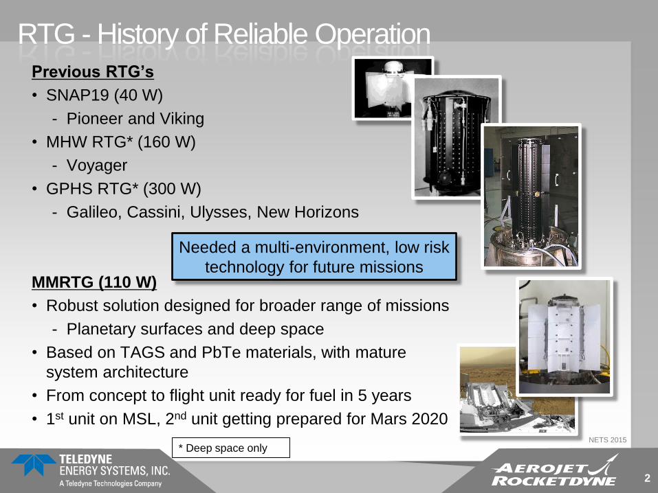
RTG - History of Reliable Operation Previous RTG’s
• SNAP19 (40 W)
- Pioneer and Viking
• MHW RTG* (160 W)
- Voyager
• GPHS RTG* (300 W)
- Galileo, Cassini, Ulysses, New Horizons
MMRTG (110 W)
• Robust solution designed for broader range of missions
- Planetary surfaces and deep space
• Based on TAGS and PbTe materials, with mature
system architecture
• From concept to flight unit ready for fuel in 5 years
• 1st unit on MSL, 2nd unit getting prepared for Mars 2020
* Deep space only
Needed a multi-environment, low risk
technology for future missions
NETS 2015
3
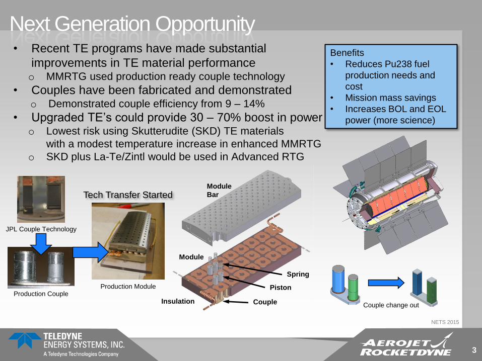
Next Generation Opportunity • Recent TE programs have made substantial
improvements in TE material performance o MMRTG used production ready couple technology
• Couples have been fabricated and demonstrated o Demonstrated couple efficiency from 9 – 14%
• Upgraded TE’s could provide 30 – 70% boost in power o Lowest risk using Skutterudite (SKD) TE materials
with a modest temperature increase in enhanced MMRTG
o SKD plus La-Te/Zintl would be used in Advanced RTG
Production Couple
JPL Couple Technology
Couple
Module
Bar
Spring
Piston
Insulation
Module
Production Module
Tech Transfer Started
Benefits
• Reduces Pu238 fuel
production needs and
cost
• Mission mass savings
• Increases BOL and EOL
power (more science)
Couple change out
NETS 2015
4
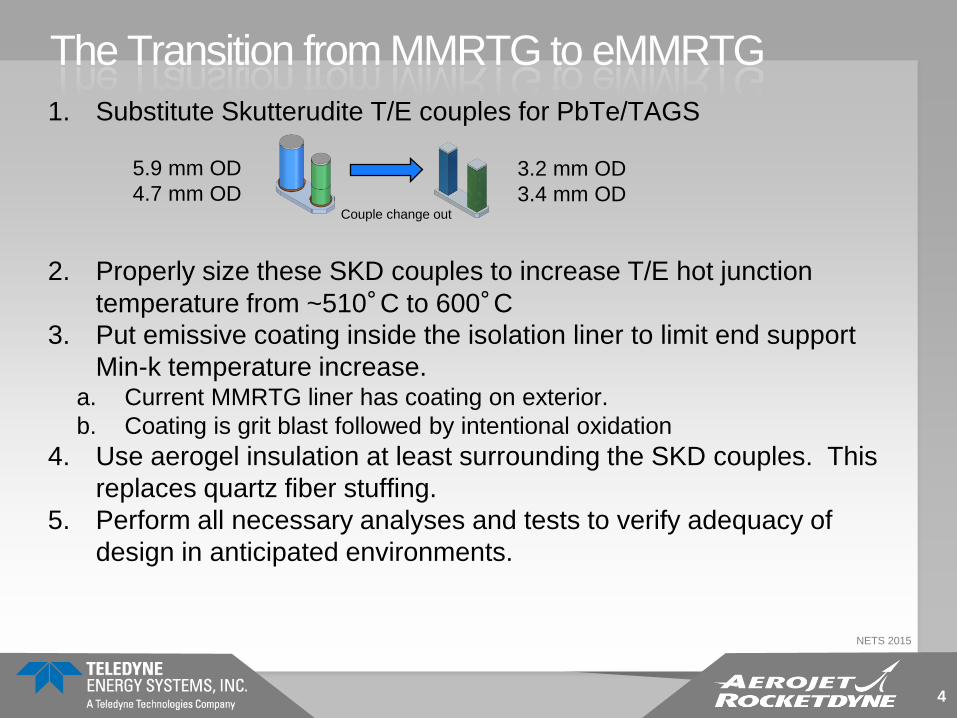
The Transition from MMRTG to eMMRTG
1. Substitute Skutterudite T/E couples for PbTe/TAGS
2. Properly size these SKD couples to increase T/E hot junction
temperature from ~510°C to 600°C
3. Put emissive coating inside the isolation liner to limit end support
Min-k temperature increase. a. Current MMRTG liner has coating on exterior.
b. Coating is grit blast followed by intentional oxidation
4. Use aerogel insulation at least surrounding the SKD couples. This
replaces quartz fiber stuffing.
5. Perform all necessary analyses and tests to verify adequacy of
design in anticipated environments.
Couple change out
5.9 mm OD
4.7 mm OD
3.2 mm OD
3.4 mm OD

NETS 2015
5
MMRTG Description • GPHS supported by load bearing
insulation under end covers
• Liner isolates He evolving in
GPHS from TE modules • He vented through end cap gasket
• Modules are in an Argon cover gas
• TE couples are compressively loaded
by springs and pistons in module
bars
• Couples connected in electrical
series-parallel circuit for additional
redundancy
Couple
Module Bar
Spring
Piston
Cold Strap
Insulation Module
Couple
GPHS
Liner
Heat Dist
Block
TE Modules
Housing

NETS 2015
6
“P ” Type SKD
“P” Leg TAGS/PbSnTe
“N” Leg PbTe
MMRTG Couple
“Drop-in Replacement” Couple
• Better high temperature capability
• Non-segmented
• Cut to shape (not pressed)
• Better mechanical properties
• Smaller element cross section • Required to increase hot side
temperature
“N” Type SKD
eMMRTG Couple
T/E Couple Assembly Comparison

NETS 2015
7
eMMRTG Engineering Efforts
• 2013 - Identify power potential and associated hot junction temperature and
changes required to the MMRTG design
- Evaluate associated risks
- Risk burn-down plan
• 2014 - All work based on design selected during 2013 work
- Evaluate three different mission profiles
- Margin analyses • Determine acceptable hot junction temperature
• Evaluate areas of concern
- Update thermal model
- Evaluate loss of argon cover gas (vacuum case)
• Over-arching ultimate goals - Trade studies to define requirements
- Settle on SKD T/E couple for testing
- and acceptable eMMRTG system design

NETS 2015
8
Three Mission Profiles – Europa, Titan and Mars
• Mission durations - Europa 11 years
- Titan 12.2 years
- Mars 5.6 years
• Maximum fin root temperatures - Europa 210C for 7 days at 29.5 VDC load
- Titan 170C for 3 years at 29.5 VDC load
- Mars 205C during Mars summer at 32.8 VDC load
• Maximum Load Voltage - 32.8 VDC
- Consider max of 36 VDC (in SRD)
NETS 2015
9
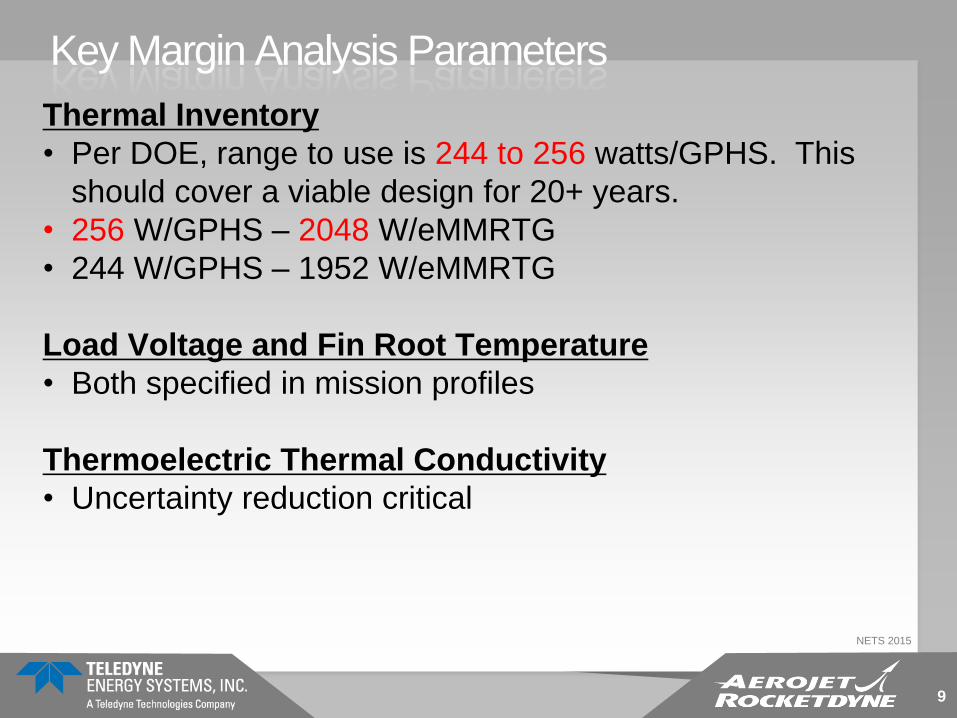
Key Margin Analysis Parameters
Thermal Inventory
• Per DOE, range to use is 244 to 256 watts/GPHS. This
should cover a viable design for 20+ years.
• 256 W/GPHS – 2048 W/eMMRTG
• 244 W/GPHS – 1952 W/eMMRTG
Load Voltage and Fin Root Temperature
• Both specified in mission profiles
Thermoelectric Thermal Conductivity
• Uncertainty reduction critical
NETS 2015
10
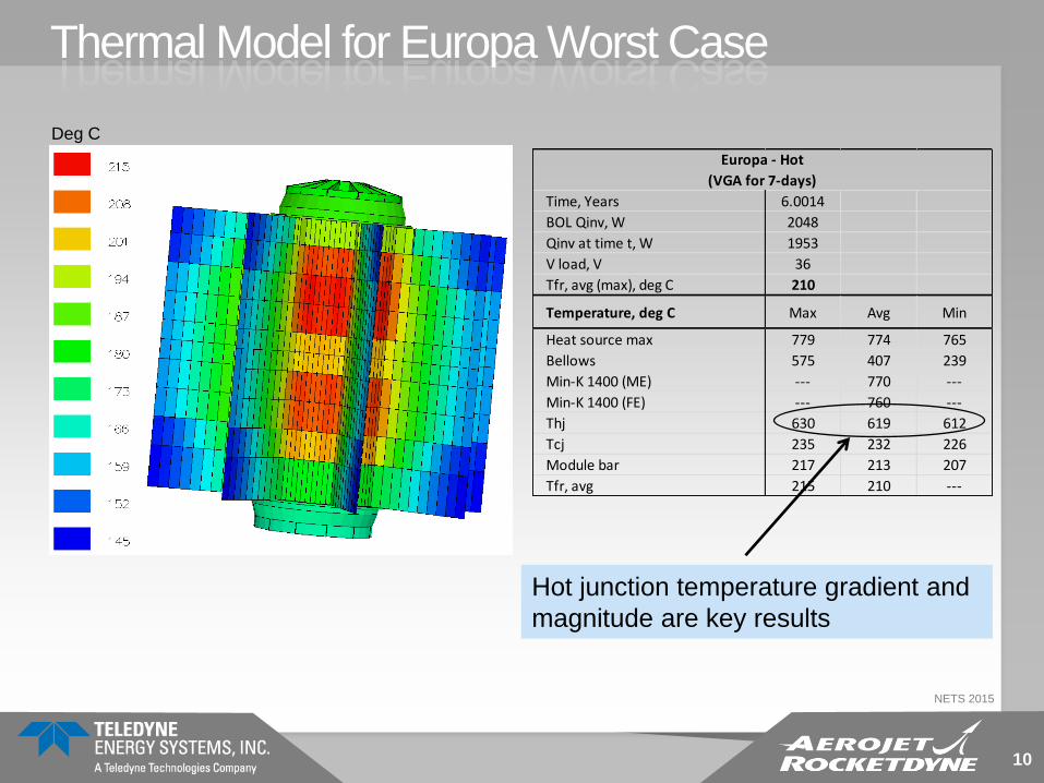
Thermal Model for Europa Worst Case
Deg C
Time, Years 6.0014
BOL Qinv, W 2048
Qinv at time t, W 1953
V load, V 36
Tfr, avg (max), deg C 210
Temperature, deg C Max Avg Min
Heat source max 779 774 765
Bellows 575 407 239
Min-K 1400 (ME) --- 770 ---
Min-K 1400 (FE) --- 760 ---
Thj 630 619 612
Tcj 235 232 226
Module bar 217 213 207
Tfr, avg 215 210 ---
Europa - Hot
(VGA for 7-days)
Hot junction temperature gradient and
magnitude are key results

NETS 2015
11
Maximum Temperature Cases for 36 vdc Load
0
100
200
300
400
500
600
700
800
900
1000
0
20
40
60
80
100
120
140
160
180
200
0 2 4 6 8 10 12 14
Tem
pe
ratu
re (
De
g. C
)
Po
we
r o
utp
ut
(wat
ts)
Mission time (years)
Europa/Titan/Mars; BOL Q = 2048w, Max TFR, EL = 36vdc
Power output, Europa Power output, TitanPower output, Mars THJ, EuropaTHJ, Titan THJ, MarsTFR, Europa TFR, TitanTFR, Mars
Load voltage = 36vdc for entire mission
Euro
pa
Tita
n
Mar
s Max THJ values occur at these points in time

NETS 2015
12
Margin Analysis Summary
Reviewed all results for Europa, Titan and Mars, full
range of load voltages and fin root temperatures, min
and max thermal inventories and launch conditions
• Worst Case Hot Observations - Fin root temperature exceeding 200°C design point for MMRTG
housing, but should be ok
- Min-k 1400 in danger zone of 760-800°C • Testing planned to evaluate
- Gasket near limit of design operation of 200°C • Needs review
- THJ near 650°C • JPL testing
• Worst Case Cold Observations - Fin root temperature below 50°C tested point
- Heat source clad just below 750°C
NETS 2015
13
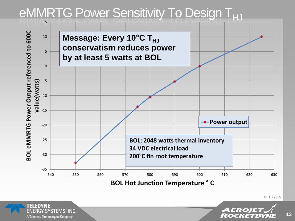
eMMRTG Power Sensitivity To Design THJ
-35
-30
-25
-20
-15
-10
-5
0
5
10
15
540 550 560 570 580 590 600 610 620 630
BO
L e
MM
RTG
Po
we
r O
utp
ut
refe
ren
ced
to
60
0C
va
lue
(wat
ts)
BOL Hot Junction Temperature ° C
Power output
BOL; 2048 watts thermal inventory 34 VDC electrical load 200°C fin root temperature
Message: Every 10°C THJ
conservatism reduces power
by at least 5 watts at BOL

NETS 2015
14
Thermoelectric Thermal Conductivity
• eMMRTG system thermal efficiency approximately 90% 90%
heat goes through T/E elements
• ΔT is 600-200 = 400°C
• SKD k uncertainty at 3 is +/- 10%
• Max THJ uncertainty is ~+/- 40°C
Excellent vehicle to evaluate k and burn down this risk is
planned
• Efficiency test planned
• By properly running this test and first testing with Min-k (or
Microtherm) in place of the TE module, this is a high accuracy
efficiency test of the TE module k test of a module of TE
elements.

NETS 2015
15
Margins Discussion
• Thermal inventory of 2048 watts - What is likelihood of 8 GPHS blocks at 256 watts each?
- Need to cover the worst case
• Actual operating load voltage is important as it affects THJ
- Design too high – too conservative
- Design too low – high THJ values at high load voltages
- Shooting now for 34 vdc
• THJ axial variation from average – 18°C - Output of thermal analysis (axial variation in eMMRTG)
- Can be reduced by optimizing the HDB – 2015 work
• Extra margin value of 20°C - Basis for this? Too much?
• TE conductivity - Knowledge, measurement and control is crucial!
NETS 2015
16
Loss Of Argon Study • Purpose – what happens with loss of gas fill (argon in converter and
helium in heat source) due to event like micrometeoroid puncture?
• Accomplishments: - Assessed temperature increase of T/E hot junction
- Assessed short term power change
- Did not assess T/E degradation effects
• How this was done - Estimated insulation thermal conductivity in vacuum
- Attempted analysis of cold end hardware effects in vacuum • Found cold end hardware test data (from 1973!) in argon, helium and vacuum
• Good example of knowledge base retention
- Modified system performance model for the above
NETS 2015
17
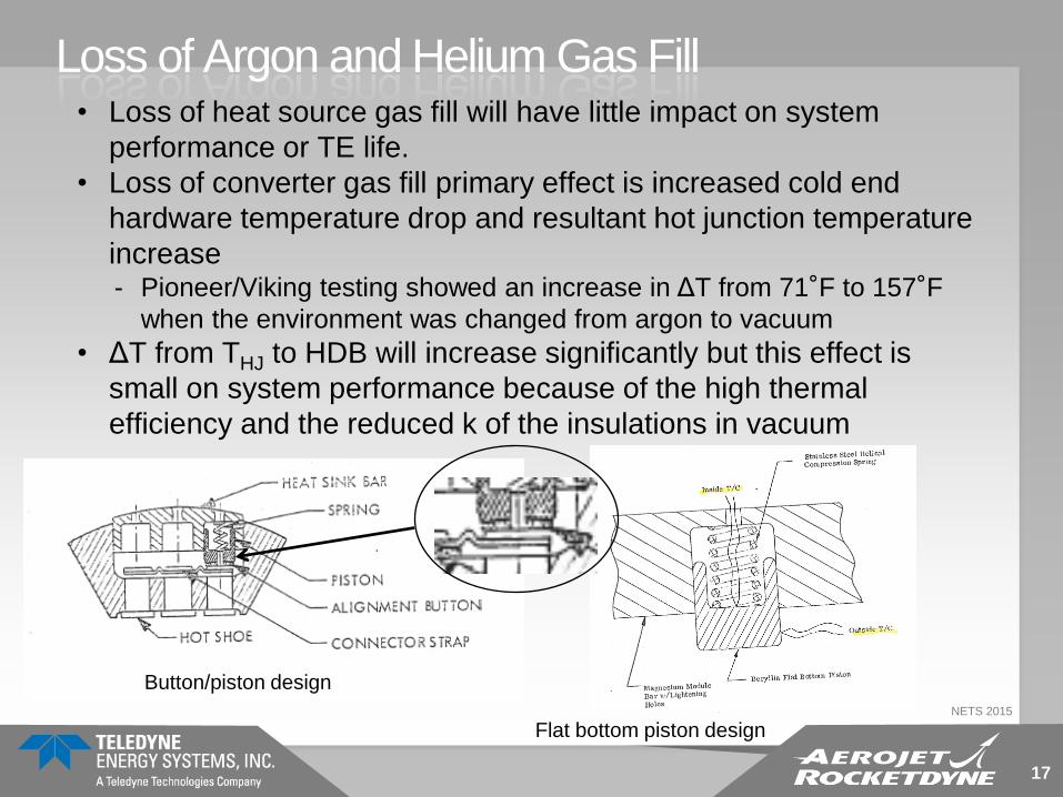
Loss of Argon and Helium Gas Fill • Loss of heat source gas fill will have little impact on system
performance or TE life.
• Loss of converter gas fill primary effect is increased cold end
hardware temperature drop and resultant hot junction temperature
increase - Pioneer/Viking testing showed an increase in ΔT from 71°F to 157°F
when the environment was changed from argon to vacuum
• ΔT from THJ to HDB will increase significantly but this effect is
small on system performance because of the high thermal
efficiency and the reduced k of the insulations in vacuum
Button/piston design
Flat bottom piston design
NETS 2015
18
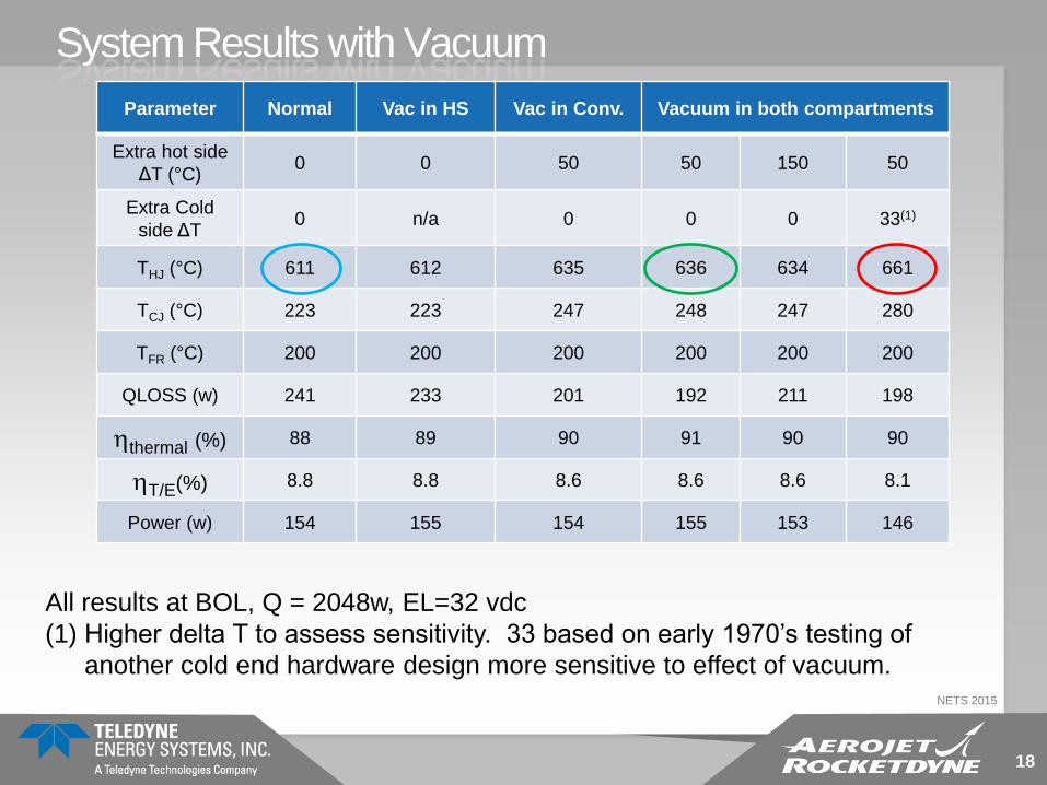
System Results with Vacuum
Parameter Normal Vac in HS Vac in Conv. Vacuum in both compartments
Extra hot side
ΔT (°C) 0 0 50 50 150 50
Extra Cold
side ΔT 0 n/a 0 0 0 33(1)
THJ (°C) 611 612 635 636 634 661
TCJ (°C) 223 223 247 248 247 280
TFR (°C) 200 200 200 200 200 200
QLOSS (w) 241 233 201 192 211 198
thermal (%) 88 89 90 91 90 90
T/E(%) 8.8 8.8 8.6 8.6 8.6 8.1
Power (w) 154 155 154 155 153 146
All results at BOL, Q = 2048w, EL=32 vdc
(1) Higher delta T to assess sensitivity. 33 based on early 1970’s testing of
another cold end hardware design more sensitive to effect of vacuum.

NETS 2015
19
Loss of Argon; Vacuum Case Summary
• Results shown at BOL – worst case and unlikely time for problem. - At 4 years, THJ results about 6°C lower
• Issue is micrometeoroid puncture
• What is life of system and resultant performance?
• Key is SKD hot junction temperature and life in vacuum
• Testing best way to assess this
• Test also recommended for cold end temperature drop verification
in vacuum
• Option to add weight for puncture armor, if puncture probability is
concern

NETS 2015
20
Planned 2015 eMMRTG Engineering Work
• Optimize the HDB – Heat Distribution Block to reduce axial
thermal gradients: thermal and structural evaluations
• Produce combined thermal/thermoelectric model to enable the
above
• Structural analysis to: - Evaluate a pre-stressed Min-k 1400 heat source support system
- Perform random vibe evaluation of eMMRTG with OHDB and SKD
couples
The authors would like to acknowledge the
support of DOE, JPL and NASA that made the
supporting studies possible.