The electrospinning platforms ES1a and ES4 5 of 43 1. Overview of the electrospinning platform 1.1....
43
Page 1 of 43 User Manual: The electrospinning platforms ES1a and ES4 ES1a ES4
-
Upload
nguyenxuyen -
Category
Documents
-
view
214 -
download
0
Transcript of The electrospinning platforms ES1a and ES4 5 of 43 1. Overview of the electrospinning platform 1.1....

Page 1 of 43
User Manual:
The electrospinning platforms ES1a and ES4
ES1a
ES4

Page 2 of 43

Page 3 of 43
Table of Contents
Table of Contents .......................................................... 3
1. Overview of the electrospinning platform ............... 5
1.1. Purpose ......................................................................... 5
1.2. Principle ........................................................................ 5
1.3. Warnings ....................................................................... 6
1.4. Specifications ................................................................ 6
2.1. Directions of use ........................................................... 7
3. General Guide ........................................................... 8
3.1. Parts checklist ............................................................... 8
3.2. Initial Assembly ............................................................. 9
3.2.1. The Assembly Test ............................................................ 10
3.3. Places of the other elements needed for
electrospinning................................................................... 10
3.4. Operation .................................................................... 11
3.5. Maintenance ............................................................... 14
4. FAQ ......................................................................... 17
4.1. How do I make up a solution of PVOH? ...................... 17
4.2. What can I use for a target? ........................................ 17
4.3. Can I use a syringe pump? .......................................... 17
4.4. What is the rate of deposition? .................................. 17

Page 4 of 43
4.5. Why doesn’t the machine need an enclosure to be
safe? ................................................................................... 18
5. Glossary .................................................................. 19
6. Appendix ................................................................. 23
Appendix I - How to specify a ventilation system when using
hazardous solvents? ........................................................... 23
Appendix II - Why doesn’t the machine need an enclosure
to be safe? .......................................................................... 25
Appendix III – Electrospinnable materials and conditions . 27
References ................................................................................... 37

Page 5 of 43
1. Overview of the electrospinning platform
1.1. Purpose The aim of this manual is to explain safe operating procedures for the
electrospinning machine (ES4 and ES1a).
1.2. Principle Electrospinning uses an electrical charge to draw very fine micro or nanofibres from
a polymer in a liquid solution or melt. The process is non-invasive and does not require the
use of coagulation chemistry or high temperatures to produce solid threads from solution.
This makes the process particularly suited to the production of fibres using large and
complex molecules.
When a sufficiently high voltage is applied to a liquid droplet, the body of the liquid
becomes charged, and electrostatic repulsion counteracts the surface tension and droplet is
stretched, and a Taylor cone appears, at a critical point a stream of liquid erupts from the
surface, at the tip of the Taylor cone.
If the molecular cohesion of the liquid is sufficiently high, stream breakup does not
occur (if it does, droplets are electrosprayed) and a charged liquid jet is formed. As the jet
dries out in flight, the mode of current flow changes from ohmic to convective as the charge
migrates to the surface of the fibre.
The jet is then elongated by a whipping process caused by electrostatic repulsion
initiated at small bends in the fibre, until it is finally deposited on the grounded collector.
The elongation and thinning of the fibre resulting from this bending instability leads to the
formation of uniform fibres with nanometre-scale diameters.
A typical electrospinning jet
Photo by R.Lamberts - PFR

Page 6 of 43
1.3. Warnings This is a research machine designed to allow maximum access to the process for
research purposes. The only pieces that are significantly live during operation are the
pipette tip, the transfer pipe and liquid within the reservoir.
The electrospinning machine runs at between 0-33,000 volts, the maximum current
delivered by the machine is 0.3mA, a level of current much lower than that required for
injuring a human. However, a shock from the machine is disagreeable – like a shock from
static discharge.
1.4. Specifications Description:
The ES1a and ES4 are designed to be used by competent operators in a laboratory environment, using an aqueous solution. Other solutions may be spun but the materials of the header tank, hose and spinning tip may need to be changed or adapted.
The ES1a, and ES4, is a one or two-part machine with a solid, easy to clean base. The constant head system is adjustable and has both coarse and fine adjustment. The moveable spinning head can be set from zero to 150mm for the ES1 and from zero to 200mm for the ES4, from the fixed target plane; this can be adjusted during operation. The power to the spinning head is adjustable from zero to + or -33,000 VDC from the separate control box. Materials:
Base and Control Box are constructed from stainless steel
Insulating materials are made of Polyoxymethylene (POM)
Target plane 300mm x 350mm x 10mm is made of polyethylene (PE)
Electrical connection fittings are made of brass
Header tank is made of borosilicate glass
Hose is made of Silicone rubber
Spinning tip is made of high density polypropylene Power Supply: Single phase 100 to 240 VAC, 1 amp maximum. Power supply socket is a DIN standard fitting; most computer cords will fit this. Contact: Electrospinz Limited 44 Lee Street Blenheim 7301 New Zealand Email: [email protected]
Phone: +64 3578 8092
Page 7 of 43
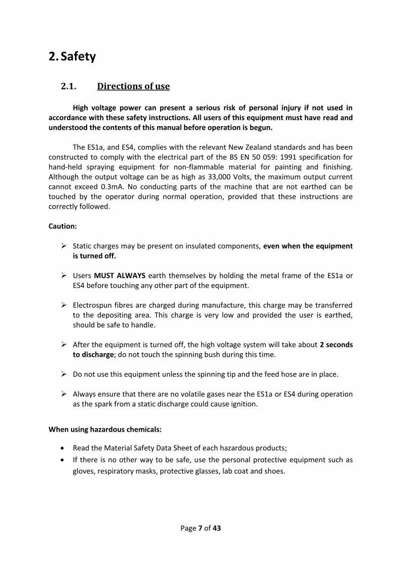
2. Safety
2.1. Directions of use High voltage power can present a serious risk of personal injury if not used in
accordance with these safety instructions. All users of this equipment must have read and understood the contents of this manual before operation is begun.
The ES1a, and ES4, complies with the relevant New Zealand standards and has been
constructed to comply with the electrical part of the BS EN 50 059: 1991 specification for hand-held spraying equipment for non-flammable material for painting and finishing. Although the output voltage can be as high as 33,000 Volts, the maximum output current cannot exceed 0.3mA. No conducting parts of the machine that are not earthed can be touched by the operator during normal operation, provided that these instructions are correctly followed. Caution: Static charges may be present on insulated components, even when the equipment
is turned off. Users MUST ALWAYS earth themselves by holding the metal frame of the ES1a or
ES4 before touching any other part of the equipment. Electrospun fibres are charged during manufacture, this charge may be transferred
to the depositing area. This charge is very low and provided the user is earthed, should be safe to handle.
After the equipment is turned off, the high voltage system will take about 2 seconds
to discharge; do not touch the spinning bush during this time. Do not use this equipment unless the spinning tip and the feed hose are in place.
Always ensure that there are no volatile gases near the ES1a or ES4 during operation
as the spark from a static discharge could cause ignition.
When using hazardous chemicals:
Read the Material Safety Data Sheet of each hazardous products;
If there is no other way to be safe, use the personal protective equipment such as
gloves, respiratory masks, protective glasses, lab coat and shoes.
Page 8 of 43
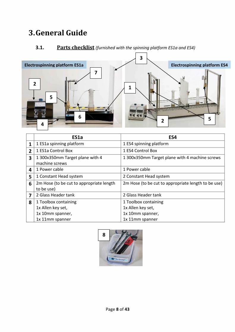
3. General Guide
3.1. Parts checklist (furnished with the spinning platform ES1a and ES4)
ES1a ES4
1 1 ES1a spinning platform 1 ES4 spinning platform
2 1 ES1a Control Box 1 ES4 Control Box
3 1 300x350mm Target plane with 4 machine screws
1 300x350mm Target plane with 4 machine screws
4 1 Power cable 1 Power cable
5 1 Constant Head system 2 Constant Head system
6 2m Hose (to be cut to appropriate length to be use)
2m Hose (to be cut to appropriate length to be use)
7 2 Glass Header tank 2 Glass Header tank
8 1 Toolbox containing 1x Allen key set, 1x 10mm spanner, 1x 11mm spanner
1 Toolbox containing 1x Allen key set, 1x 10mm spanner, 1x 11mm spanner
Electrospinning platform ES1a Electrospinning platform ES4
1
5
3
2
2
5
8
7
6
4

Page 9 of 43
3.2. Initial Assembly
A. Unpack and check that the parts are all present.
B. Remove the four machine screws and mount the target plane to the end of the spinning platform (in the middle for ES4), do not over tighten the screws.
C. Install the constant head system as shown.
D. Plug the spinning platform lead into the back of the control box.
E. Plug the power cable into the back of the control box, and to the power supply.

Page 10 of 43
3.2.1. The Assembly Test
F. Check that the earthed power outlet has a good earth by plugging in the power lead with the switch OFF and checking for Voltage to another earthed point. This check should be repeated each time the ES1a is used, to keep the power supply.
G. Turn on the power at the wall, ensure that the HV Adj. Knob is turned to Zero and turn on the ES1a, the blue light on top of the control box should light up.
H. Turn the HV Adjuster knob slowly to full power and back, the meter should smoothly move between 0 and 33kV.
I. Turn off the ES1a or the ES4, it is ready to use.
3.3. Places of the other elements needed for electrospinning
Header
Tank
Spinning Post
Spinning Tip
Spinning Bush
Silicone Hose Control Box
Target
Earth Stud

Page 11 of 43
3.4. Operation
1. Perform the previous assembly test F. to I.
2. Place the glass header tank between the tongs of the constant head system.
3. Insert the spinning bush at the top of the spinning post. 4. Connect the hose from the header tank to the spinning bush.
5. Insert the spinning tip over the spigot on the other side of the spinning bush.
6. Place a collector on the target, such as an aluminium foil or a metallic plate.
7. Earth the target area: connect the target to the ES1a or ES4 metallic platform. If this is not done then the fibres will be drawn to the nearest earthed thing. This is not necessarily the ES1a or ES4; it may be any structure within reach.

Page 12 of 43
8. Pour the prepared polymer into the header tank.
9. Raise the header tank to allow the liquid to flow to the tip of the spinning needle,
with the course or manually.
10. Maintain the header tank to hold a small droplet of polymer at the spinning tip. A piece of paper towel may be placed on the ES1a or ES4 bed between the spinning tip and the target plane to assist with cleaning.
11. When the polymer is seen to be almost at the spinning tip lower the header tank to provide a head of about 15mm above the spinning tip. This will need to be adjusted once spinning has begun.
15 mm
Page 13 of 43
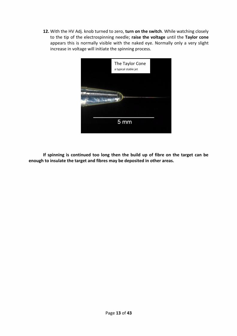
12. With the HV Adj. knob turned to zero, turn on the switch. While watching closely to the tip of the electrospinning needle; raise the voltage until the Taylor cone appears this is normally visible with the naked eye. Normally only a very slight increase in voltage will initiate the spinning process.
If spinning is continued too long then the build up of fibre on the target can be enough to insulate the target and fibres may be deposited in other areas.
The Taylor Cone a typical stable jet

Page 14 of 43
3.5. Maintenance Cleaning
A. Remove the header tank, hose and spinning tip. Move these to the cleaning area.
B. Remove the spinning bush; use the 10mm spanner if required.
C. Do not remove the brass spinning bush holder!
D. The spinning bush is made from stainless steel and should be thoroughly washed and dried before reassembly.
E. The spinning tip may be cleaned but is designed as a disposable item.
F. Clean the base of the machine with a damp cloth or a cloth dampened with a little solvent. Be careful with solvents around the plastic components as these may be damaged by some solvents.
G. Reassemble in the reverse order, be careful not to over tighten the nut on the spinning bush, finger tight is usually enough.
Servicing
The ES1a and ES4 have been designed to be serviced without returning it to
Electrospinz Limited. The electrical system must be serviced only by qualified personal and must be
maintained in compliance with the relevant local legislation. Replacement components are available worldwide and should be obtained locally.
The mechanical components should be serviced by a competent person, any required special parts can be ordered from Electrospinz Limited.

Page 15 of 43
Circuit Diagram
Any servicing of the electrical system must be done by a qualified person in accordance with local requirements.
Wire numbers shown are for the Plug, socket, multi-core cable and HV power supply.

Page 16 of 43

Page 17 of 43
FAQ
How do I make up a solution of PVOH?
Polyvinyl Alcohol (PVOH) is soluble in water, but you should heat the
distilled water to 60°C, and the powdered polymer (7-8wt %) should be
stirred in very gradually to avoid the formation of lumps.
What can I use for a target?
Domestic aluminium foil works very well and sets of identified sample
plates are available. Handle with gloves to avoid the transfer of grease and
moisture from your hands. The target will need to be connected to earth
through any part of electrospinner chassis, or the earth stud.
Can I use a syringe pump?
If you wish – the Electrospinz platform works by the constant pressure
feed header tank with a wide range of polymers and solvent, but if you are
working with an exceptionally viscous material, a syringe pump may be the
answer. The pump can be connected through the spinning bush and pipette
in the normal way.
What is the rate of deposition?
The rate is dependent on your choice of polymer system, but will
decline with time, as the deposited fibre acts as an insulator, and allows a
charge to build up on the target, The PVOH supplied will initially deposit at
about 140µg/s after about 10 minutes.

Page 18 of 43
Why doesn’t the machine need an enclosure to be safe?
The Electrospinz machines are designed to have an intrinsic low
capacitance. This is achieved by minimising the amount of metal surfaces that
are charged by the power supply and the bonding to earth of all the metal
surfaces of the machine. Good bond continuity is ensured by welding the
component parts of the structure together. These design principles result in
a machine capacitance of less than 10pF. Surrounding the machine with an
insulating cabinet would increase the capacitance of the system.
Low machine capacitance is an important safety feature for the
following reasons. When the machine capacitance (>10pF) is considered in
connection with a human body, resistance of approximately 500 ohms (IEC
2005), this means the capacitive charge will discharge in under a millisecond
leaving only the continuous supply capacity of the power supply to contend
with in terms of risk of ventricular fibrillation (disruption of the activity of the
heart). - Cf. Appendix II:Why doesn’t the machine need an enclosure to be
safe?

Page 19 of 43
Glossary
Aligned fibres: electrospun nanofibres which are parallel to each other.
(Applied) Voltage/Potential Difference: The voltage applied to the solution via the
control box. A typical voltage used for electrospinning is 10kV.
Control Box: regulates the applied voltage and therefore the electrospinning
process.
Deposition Process: how the fibres are depositing on the target.
Earth Stud/Electric Current Collector: connected to the earth, this device allows the
current to circulate, and therefore, electrospinning to occur. This system is also
designed to electrically discharge each metallic part of the platform is an important
safety part of the machine.
Electrospinning: The operation of creating nanofibres from a polymer dissolved in a
solution by applying a voltage to that liquid.
Electrospinning Jet: the jet formed by the liquid at the tip of the needle, between
the Taylor cone and the whipping instability.
Laboratory Electrospinning Platform: the name of the machine for electrospinning.
“platform” indicates that the machine is designed to be modified for research
purposes.
Electrospun nanofibres: nanofibres which are created through an electrospinning
process. Nanofibres are considered to be less than 100nm in diameter.
Electrospraying: the operation of creating droplets with a nano-size through a
similar process used for electrospinning.
Feed Pipe/Silicone Pipe/Feed Hose: a plastic hose used to connect the reservoir to
the spinning tip via the metallic spinning bush.
Flow Rate/ Mass Flow Rate: The flow speed of the liquid, effectively the spinning
speed of the process.

Page 20 of 43
Fluid Pressure: Pressure applied to the fluid to regulate the flow, and therefore,
stabilize the electrospinning process. This can be controlled in increasing or
decreasing the height of the Header Tank.
Grounded Collector/Target Substrate/Grounded Electrode: the object used to
collect the fibres; it may different shapes according to the kind of fibres wanted: a
simple metallic plate or aluminium foil results in the creation of random fibres but a
metallic wire frame results in the creation of aligned fibres. This collector must be
connected to the earth to avoid charge accumulation.
High Voltage Electric Current: The electric current that circulates between the
spinning tip and the grounded collector. The maximum current which can be
produced is under 0.33 mA. (See FAQ: Why doesn’t the machine need an enclosure
to be safe?)
Mass Deposition Rate: The mass of fibres produced within a certain amount of time.
Magnetisation: While using a metallic plate as a collector, using a magnet to keep
the plate vertical will be useful. However, during the process, the plate will acquire a
certain magnetisation that may interfere with the weighing process and
misrepresents the real amount of fibres which have been deposited on the plate.
Using a demagnetizer after electrospinning can prevent interferences while weighing
the plate. This effect is only noticeable when using a 4 figure balance.
Nanofibres: Fibres which diameter of less than 100 nanometres.
Porous surface and smooth fibres: Nanofibres can have varying surface’s
morphologies for example the fibre surface may be pitted or smooth.
Removable Spinning Bush/Metallic Connector: This element makes the connexion
between the silicone hose and the spinning tip. It is connected to the high voltage
supply.
Reservoir/Header Tank: contains a certain amount of liquid and by varying the
height of the reservoir controls the pressure or head of the flowing liquid.
SEM (Scanning Electron Microscope): A type of electron microscope that produces
images of a sample by scanning it with a focused beam of electrons. The electrons
interact with atoms in the sample, producing various signals that can be detected
and that contain information about the sample's surface topography and
Page 21 of 43
composition. The electron beam is generally scanned in a raster scan pattern, and
the beam's position is combined with the detected signal to produce an image. SEM
can achieve resolution better than 1 nanometre.
Spinning Post or Electrode/High Voltage Electrode: This part of the electrospinning
platform keep the spinning bush and tip straight at a certain height aligned with the
target. An electric wire is inside making the contact between the high voltage supply
and the metallic connector, allowing the current to circulate.
Spinning Tip or Needle/Spinneret: A conic tube with a very small exit at the tip,
reducing considerably the flow of liquid allowing adjustments to the flow just by
modifying the height of the header tank. It is positioned at the tip of the metallic
connector. A micropipette tip or hypodermic syringe needle is often used.
Stable or continuous jets: The stable part of the jet starts with a Taylor cone at the
tip of the spinning needle. To achieve this, it is necessary to adjust the flow of liquid:
if it is too quick, there will be a large droplet at the tip of the needle and the jet will
not be continuous, if it is too slow, there will be a too small Taylor cone and the jet
will not be continuous either. It is also possible to modify the tension applied to the
fluid to obtain the Taylor cone, the higher the voltage will be, the higher the fluid
consumption and flow rate will be.
Straight Jet/Axisymetric Jet: The straight jet is a jet usually formed after the Taylor,
before it begins to whip. This or those jet(s) is/are more or less longer depending in
the parameters: the kind of solution used, the distance between the needle tip and
the collector, the kind of collector and the applied voltage.
Surface tension: The surface tension of a liquid is an important parameter while
doing electrospinning. It is a contractive tendency of the surface of a liquid that
allows it to resist an external force. This property is caused by cohesion of similar
molecules, and is responsible for certain of liquids’ properties. Therefore it is a useful
parameter to know while creating solutions for electrospinning. Surface tension has
the dimension of force per unit length or of energy per unit area.
Taylor Cone: The cone observed at the tip of the spinning needle when high voltage
is applied to the liquid, it is apparent as a deformation at the end of the liquid
meniscus at the spinning tip. The apex of the cone is the point of ejection of the
liquid stream what forms the jet. The cone is named after Sir Geoffroy Ingram Taylor
(1886 – 1975) who first described it.

Page 22 of 43
TCD (Tip to Collector Distance): It’s the distance between the spinning tip and the
grounded collector, a typical TCD used for electrospinning is 10 cm.
Uniform fibres: fibres are uniform when they have the same characteristics:
diameter, alignment, and morphology.
Whipping or Bending Instability/Whipping Envelope: During its flight, the jet is
drying out and at a variable distance from the needle, the jet starts to whip and bend
until it arrives at the collector. At its arrival, the jet is ideally only composed by the
polymer; the solvent has all been lost in flight. Strictly speaking the flight path of the
jet is an expanding helix, but this is commonly called the whipping instability.

Page 23 of 43
4. Appendix
Appendix I - How to specify a ventilation system when using
hazardous solvents?
Some solvent and diluents systems used in electrospinning are hazardous by contact
or inhalation. To limit any hazards caused by the normal evaporation rate of the solvent to
the atmosphere, it is recommended to use a lid on the header tank – usually a watch glass.
The Electrospinz machine is designed to fit inside standard laboratory fume
cupboards. This is the recommended method of limiting operator exposure to solvents
fumes. It may be necessary to switch off the fume cupboard ventilation during spinning to
avoid the fibres being sucked away by the ventilation fan. The fume cupboard door should
therefore be kept closed during spinning.
The laboratory ventilation system should be checked if such solvents are used. If you
do not have access to a fume cupboard, you should assess if the ventilation in your
laboratory is adequate.
To do this you need to know the safe exposure limit of the solvent. This can be found
in the Material Safety Data sheet for the solvent. It is also important to know the volume of
the room where the electrospinning will occur.
As an example, we will consider the use the Hexafluroisopropanol in a room with a
volume of 140 m3. The exposure limit of this solution is 2.5 mg/m3, so the limit will be
reached when 3500 mg of solvent has evaporated. (140 m3 * 2.5mg/m3)
What we need to know next, is the amount of time necessary to reach that limit, for
that purpose we can use the evaporation rate of PVOH in water which is 60 mg/h, during
electrospinning.
Then we can calculate the amount of time to reach the limit:
But this evaporation rate is true only for the PVOH so we must apply safety
coefficients to that calculation, x5 or x10 are a safe allowance.

Page 24 of 43
With an evaporation rate multiplied by 5, we find this result:
With an evaporation rate of 10, we find this result:
Those times means that the room air would need to be completely renewed within
1h or 35 minutes depending on the safety level required. Depending on the hazards and the
amount of product used, it would be better to apply the safety rating of 5 or 10. Even if the
spinning platform is completely isolated, it is strongly recommended to always wear a
respirator when using these kinds of hazardous chemicals.

Page 25 of 43
Appendix II - Why doesn’t the machine need an enclosure to be
safe? An Electrospinz machine, at maximum current output (short circuit conditions) cannot
produce enough current to disrupt the action of the heart [1]. It can be calculated that for
the supply to produce enough energy to disrupt the activity of the heart, the victim [2]
would need to be in contact with a live part of the machine for more than five hours [3].
[1] Minimum current required to produce Ventricular Fibrillation irrespective of voltage
A s
s A s
A s
s
Note: The EMCO high voltage power supply cannot supply more than 0.33mA or
0.33 x 10⁻³A.
[2] There may be potential danger to those with a very weak heart or a pacemaker;
users who fall into either of these categories are advised to consult their doctor as to
the likely risk in their particular case.
[3] For an impulse current I Amps of short duration t < 10ms through the body, the
principal factor for the initiation of ventricular fibrillation is the value of I x t
(Intensity x time) or I2t (IEC 2007). At high applied voltages, the resistance of the
adult body (left hand to right hand) is at least 575 ohms for 95% of the population
(IEC 2005). Note that the figures quoted for resistance are typical for a healthy adult,
and refer to the resistance measured through dry skin, if the skin is punctured or
wet, then the resistance is reduced.
The IEC gives a threshold value of Specific Fibrillation Energy, for a 1 ms current
impulse, of 2 x 10⁻³ A2s. Below this threshold there is no evidence of fibrillation. The
Specific Fibrillation Energy can be regarded as the energy dissipated per unit
resistance of the body through which the current flows. Note that ‘specific’ here
means ‘per unit resistance’ rather than ‘per unit mass’.

Page 26 of 43
Time required producing Ventricular Fibrillation with EMCO supply:
A s
A A s
A s
A
References
IEC 2007. IEC/TS 60479-2:2007. Effects of human beings and livestock – Part 2: Special
aspects.
IEC 2005. IEC/TS 60479-1:2005. Effects of human beings and livestock – Part 1: General
aspects.

Page 27 of 43
Appendix III – Electrospinnable materials and conditions
Synthetic Polymers
Polyethylene oxide (PEO)
Solvents Typical Processing
Parameters
Processing Parameters
Range References
Water, Acetone
(Megelski et al.,
2002)
Chloroform, Ethanol,
N,N –
Dimethylformamide
(DMF)
(Son et al., 2004a)
0.5 M Acetic Acid
(Bhattarai et al.,
2005)
Water/Methanol
(90:10)
(Kessick and Tepper,
2004)
Water/Ethanol
(60:40)
(Reneker et al.,
2000)
Concentration: ~10%
(Megelski et al.,
2002)
Molecular Weight:
~400,000
(Deitzel et al.,
2001a)
Voltage: 10 kV – 20
kV
(Son et al., 2004a)
Distance: ~15 cm
(Deitzel et al.,
2001a)
Electric Field: 0.5
kV/cm – 1 kV/cm
(Shin et al., 2001a)
Conc.: 1% (Doshi and
Reneker, 1995) - 10%
(Deitzel et al., 2001b)
Mw: 300,000 (Sun et al.,
2006) -2,000,000 (Shin
et al., 2001b)
Voltage: 1 kV (Sun et
al., 2006) – 30 kV
(Kidoaki et al., 2005)
Distance: 5 cm (Kidoaki
et al., 2005) -40 cm
(Theron et al., 2005)
Electric Field: 0.2 (Doshi
and Reneker, 1995) –
3.2 kV/cm (Yarin and
Zussman, 2004)
(Bhattarai et al., 2005,
Deitzel et al., 2001a,
Deitzel et al., 2001b,
Doshi and Reneker, 1995,
Fong et al., 1999,
Hohman et al., 2001,
Huang et al., 2003,
Kessick et al., 2004,
Kessick and Tepper, 2004,
Kidoaki et al., 2005,
Megelski et al., 2002,
Reneker et al., 2000, Shin
et al., 2001a, Shin et al.,
2001b, Son et al., 2004a,
Spivak et al., 2000, Sun et
al., 2006, Theron et al.,
2005, Wang et al., 2004,
Yarin et al., 2001, Yarin
and Zussman, 2004)

Page 28 of 43
Polyvinyl alcohol (PVOH)
Solvents Typical Processing
Parameters
Processing Parameters
Range References
Water
(Koski et al., 2004)
Ethanol/Water (1:1)
(Theron et al., 2004)
Aqueous Acetic Acid
(Duan et al., 2006)
Concentration: ~ 8%
(Wang et al., 2006b)
Molecular Weight: ~
80,000
(Guan et al., 2003b)
Voltage: ~ 20kV
(Ding et al., 2002)
Distance: ~ 10cm
(Son et al., 2005)
Electric Field: ~ 1.5
kV/cm
(Duan et al., 2006)
Conc.: 4.1% (Shao et
al., 2003) - 18% (Ding
et al., 2002)
Conc.: 2.8e-7 mol/L
(Ding et al., 2002) –
2.9e-6 mol/L (Lee et al.,
2004)
Mw: 10,000 (Theron et
al., 2004) -185,000
(Koski et al., 2004)
Voltage: 5kV (Zhang et
al., 2005) – 100kV
(Theron et al., 2004)
Distance: 3.5 cm
(Morozov et al., 1998) -
25 cm (Wang et al.,
2004)
Electric Field: 0.3
kV/cm (Zhang et al.,
2005) – 4 kV/cm (Lee et
al., 2004)
(Ding et al., 2002, Ding et
al., 2004, Duan et al.,
2006, Guan et al., 2003a,
Guan et al., 2003b, Guan
et al., 2003c, Koski et al.,
2004, Lee et al., 2004,
Morozov et al., 1998,
Ohkawa et al., 2004,
Ristolainen et al., 2006,
Shao et al., 2003, Shenoy
et al., 2005b, Son et al.,
2005, Theron et al., 2004,
Wang et al., 2006b,
Wang et al., 2004, Yao et
al., 2003, Zhang et al.,
2005)

Page 29 of 43
Polystyrene (PS)
Solvents Typical Processing
Parameters
Processing Parameters
Range References
N,N –
Dimethylformamide,
Toluene
(Megelski et al.,
2002)
Carbon Disulfide
(CS2)
(Eda et al., 2007b)
Chloroform,
Tetrahydrofuran
(THF),
Methylethylketone
(Jarusuwannapoom
et al., 2005)
Acetic Acid
(Wannatong et al.,
2004)
Concentration: ~20%
(Shin et al., 2005)
Molecular Weight:
200,000 – 300,000
(Jarusuwannapoom
et al., 2005)
Voltage: ~30 kV
(Eda et al., 2007b)
Distance: ~15 cm
(Wang et al., 2006a)
Electric Field: ~1
kV/cm
(Sundaray et al.,
2004)
Conc.: 2.5% (Eda et al.,
2007a) - 35% (Casper et
al., 2004)
Conc.: 1.4e-8 mol/L (Eda
et al., 2007a) – 1.7e-5
mol/L (Casper et al.,
2004)
Mw: 4,000 (Wang et al.,
2006a) – 1,880,000
(Wang et al., 2006a)
Voltage: 3 kV (Sundaray
et al., 2004) – 30 kV
(Wannatong et al.,
2004)
Distance: 3 cm
(Sundaray et al., 2004)
– 35 cm (Casper et al.,
2004)
Electric Field: 0.14
kV/cm (Megelski et al.,
2002) – 3 kV/cm (Eda et
al., 2007b)
(Casper et al., 2004, Eda
et al., 2007b, Eda et al.,
2007a, Fong and
Reneker, 1999,
Jarusuwannapoom et al.,
2005, Megelski et al.,
2002, Shenoy et al.,
2005a, Shin et al., 2005,
Sundaray et al., 2004,
Wang et al., 2006a,
Wannatong et al., 2004)

Page 30 of 43
Polyacrylonitrile (PAN)
Solvents Typical Processing
Parameters
Processing Parameters
Range References
N,N –
Dimethylformamide
(DMF)
(Smit et al., 2005)
Concentration: 10%
(Kim and Yang,
2003)
Molecular Weight:
~75,000
(Qin et al., 2004)
Voltage: 10-25 kV
(Kim and Yang,
2003)
Distance: ~16cm
(Samatham and
Kim., 2006)
Electric Field: ~1.7
kV/cm
(Ko et al., 2003)
Conc.: 4% (Qin et al.,
2007) - 14% (Qin et al.,
2005)
Conc.: 3.8e-4 mol/L
(Sutasinpromprae et
al., 2006) – 3.2e-3 mol/L
(Sutasinpromprae et
al., 2006)
Mw: 55,000
(Sutasinpromprae et
al., 2006) – 210,000
(Smit et al., 2005)
Voltage: 5 kV (Qin et
al., 2004) – 40 kV (Qin
et al., 2007)
Distance: 10 cm –
(Sutasinpromprae et
al., 2006) 30 cm
(Sutasinpromprae et
al., 2006)
Electric Field: 0.3
kV/cm (Samatham and
Kim., 2006) – 3 kV/cm
(Sutasinpromprae et
al., 2006)
(Ko et al., 2003, Smit et
al., 2005,
Sutasinpromprae et al.,
2006, Qin et al., 2007,
Kim and Yang, 2003,
Samatham and Kim.,
2006, Qin et al., 2004,
Qin et al., 2005)

Page 31 of 43
Biopolymers
Polycaprolactone (PCL)
Solvents Typical Processing
Parameters
Processing Parameters
Range References
Chloroform/Methan
ol (3:1)
(Dalton et al., 2005)
Toluene/Methanol
(1:1),
Dichloromethane/M
ethanol (3:1),
Acetone
(Theron et al., 2004)
Concentration: ~10%
(Theron et al., 2004)
Molecular Weight:
~80,000
(Zhang et al., 2004)
Voltage: ~15 kV
(Dalton et al., 2005)
Distance: ~12 cm
(Zhang et al., 2004)
Electric Field: ~1
kV/cm
(Duling et al., 2008)
Conc.: 5% (Lee et al.,
2008)
- 12% (Fridrikh et al.,
2003)
Conc.: 2.5e-4 (Lee et al.,
2008) - 1.3e-3 (Zhang et
al., 2004)
Mw: 80,000 (Theron et
al., 2004) – 200,000
(Lee et al., 2008)
Voltage: 12 kV (Theron
et al., 2004) – 20 kV
(Lee et al., 2008)
Distance: 10 cm (Lee et
al., 2008) – 15cm
(Dalton et al., 2005)
Electric Field: 1 kV/cm
(Dalton et al., 2005) – 2
kV/cm (Lee et al., 2008)
(Dalton et al., 2005,
Fridrikh et al., 2003,
Theron et al., 2004,
Zhang et al., 2004, Lee et
al., 2008, Duling et al.,
2008)

Page 32 of 43
Polylactic acid (PLA, PLLA, PDLA)
Solvents Typical Processing
Parameters
Processing Parameters
Range References
N,N –
Dimethylformamide
(DMF),
N,N –
Dimethylformamide
(DMF) / Methylene
chloride
(Zong et al., 2002)
Dichloromethane
(Shenoy et al.,
2005a)
Dichloroethane,
Chloroform
(Zeng et al., 2003a)
Concentration: ~10%
(Zeng et al., 2003a)
Molecular Weight:
~109,000
(Zong et al., 2002)
Voltage: ~25 kV
(Ko et al., 2003)
Distance: ~15 cm
(Zong et al., 2002)
Electric Field: ~2
kV/cm
(Zong et al., 2002)
Conc.: 3% (Shenoy et
al., 2005a) - 40% (Zong
et al., 2002)
Conc.: 4.5e-5 (Shenoy et
al., 2005a) – 4.0e-3
(Zong et al., 2002)
Mw: 48,000 (Zeng et al.,
2003a) – 670,000
(Shenoy et al., 2005a)
Voltage: 20 kV (Zong et
al., 2002) – 41 kV (Zeng
et al., 2003b)
Distance: 15 cm (Ko et
al., 2003) – 20 cm (Zeng
et al., 2003b)
Electric Field: 0.75
kV/cm (Zeng et al.,
2003a) – 2 kV/cm (Zeng
et al., 2003b)
(Ko et al., 2003, Zong et
al., 2002, Zeng et al.,
2003b, Shenoy et al.,
2005a, Zeng et al.,
2003a)

Page 33 of 43
Cellulose Acetate (CAc)
Solvents Typical Processing
Parameters
Processing Parameters
Range References
Acetone/Dimethylac
etimide (DMAc) (2:1)
(Ding et al., 2004)
Acetone/water (5-
20% wt water)
(Son et al., 2004b)
Acetic Acid
(Han et al., 2008)
Dimethylformamide
(Tungprapa et al.,
2007)
Concentration: ~16%
(Tungprapa et al.,
2007)
Molecular Weight:
30,000
(Han et al., 2008)
Voltage: ~16 kV
(Chen et al., 2008)
Distance: ~15 cm
(Ding et al., 2004)
Electric Field: ~1.3
kV/cm
(Ding et al., 2004)
Conc.: 3% (Chen et al.,
2008) - 21% (Son et al.,
2004b)
Conc.: 6.0e-4 (Chen et
al., 2008) – 7.0e-3 (Son
et al., 2004b)
Mw: 30,000 (Son et al.,
2004b) – 50,000 (Chen
et al., 2008)
Voltage: 8 kV (Son et
al., 2004b) – 25 kV (Han
et al., 2008)
Distance: 6 cm (Son et
al., 2004b) – 45 cm
(Chen et al., 2008)
Electric Field: 0.4
kV/cm (Chen et al.,
2008) – 2.5 kV/cm (Han
et al., 2008)
(Ding et al., 2004, Son et
al., 2004b, Chen et al.,
2008, Han et al., 2008,
Tungprapa et al., 2007)
Page 34 of 43
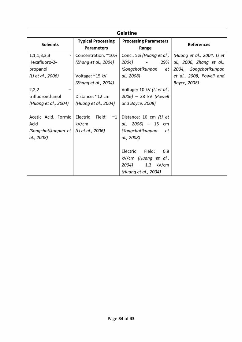
Gelatine
Solvents Typical Processing
Parameters
Processing Parameters
Range References
1,1,1,3,3,3 -
Hexafluoro-2-
propanol
(Li et al., 2006)
2,2,2 –
trifluoroethanol
(Huang et al., 2004)
Acetic Acid, Formic
Acid
(Songchotikunpan et
al., 2008)
Concentration: ~10%
(Zhang et al., 2004)
Voltage: ~15 kV
(Zhang et al., 2004)
Distance: ~12 cm
(Huang et al., 2004)
Electric Field: ~1
kV/cm
(Li et al., 2006)
Conc.: 5% (Huang et al.,
2004) - 29%
(Songchotikunpan et
al., 2008)
Voltage: 10 kV (Li et al.,
2006) – 28 kV (Powell
and Boyce, 2008)
Distance: 10 cm (Li et
al., 2006) – 15 cm
(Songchotikunpan et
al., 2008)
Electric Field: 0.8
kV/cm (Huang et al.,
2004) – 1.3 kV/cm
(Huang et al., 2004)
(Huang et al., 2004, Li et
al., 2006, Zhang et al.,
2004, Songchotikunpan
et al., 2008, Powell and
Boyce, 2008)

Page 35 of 43
Zein
Solvents Typical Processing
Parameters
Processing Parameters
Range References
Ethanol/Water (4:1)
(Miyoshi et al., 2005)
Acetic Acid,
Isopropyl
Alcohol/Water (4:1),
Ethanol/Water (3:2)
(Selling et al., 2007)
Dimethylformamide
(Jiang et al., 2007)
Concentration: ~25%
(Miyoshi et al., 2005)
Voltage: ~20 kV
(Jiang et al., 2007)
Distance: ~10 cm
(Selling et al., 2008)
Electric Field: ~2
kV/cm
(Yao et al., 2007)
Conc.: 17% (Selling et
al., 2008) - 50% (Yao et
al., 2007)
Voltage: 8 kV (Miyoshi
et al., 2005) – 40 kV
(Selling et al., 2007)
Distance: 5 cm (Selling
et al., 2007) – 25 cm
(Jiang et al., 2007)
Electric Field: 0.5
kV/cm (Jiang et al.,
2007) – 4 kV/cm
(Selling et al., 2007)
(Miyoshi et al., 2005,
Selling et al., 2007, Jiang
et al., 2007, Yao et al.,
2007, Selling et al., 2008)

Page 36 of 43
Melt Spinning
Polypropylene (PP)
Solvents Typical Processing
Parameters
Processing Parameters
Range References
Polymer Temp:
~285oC
(Lee and Obendorf,
2006)
Molecular Weight:
~200,000
(Dalton et al., 2007)
Voltage: ~20 kV
(Dalton et al., 2007)
Distance: ~4 cm
(Dalton et al., 2007)
Electric Field: ~ 5
kV/cm
(Dalton et al., 2007)
Polymer Temp: 200oC
(Lyons et al., 2004) –
320oC (Dalton et al.,
2007)
Mw: 14,000 (Lyons et
al., 2004) – 580,000
(Lyons et al., 2004)
Voltage: 10 kV (Lee and
Obendorf, 2006) – 30
kV (Lyons et al., 2004)
Distance: 2 cm (Lyons
et al., 2004) – 7 cm (Lee
and Obendorf, 2006)
Electric Field: 1.4
kV/cm (Lee and
Obendorf, 2006) – 15
kV/cm (Lyons et al.,
2004)
(Lee and Obendorf, 2006,
Lyons et al., 2004, Dalton
et al., 2007)
Page 37 of 43
References
BHATTARAI, N., EDMONDSON, D., VEISEH, O., MATSEN, F. A. & ZHANG, M. (2005)
Electrospun chitosan-based nanofibers and their cellular compatibility. Biomaterials,
26, 6176-6184.
CASPER, C. L., STEPHENS, J. S., TASSI, N. G., CHASE, D. B. & RABOLT, J. F. (2004) Controlling
Surface Morphology of Electrospun Polystyrene Fibers: Effect of Humidity and
Molecular Weight in the Electrospinning Process. Macromolecules, 37, 573-578.
CHEN, L., BROMBERG, L., HATTON, T. A. & RUTLEDGE, G. C. (2008) Electrospun cellulose
acetate fibers containing chlorhexidine as a bactericide. Polymer, 49, 1266-1275.
DALTON, P. D., GRAFAHREND, D., KLINKHAMMER, K., KLEE, D. & MOLLER, M. (2007)
Electrospinning of polymer melts: Phenomenological observations. Polymer, 48,
6823-6833.
DALTON, P. D., KLEE, D. & MOLLER, M. (2005) Electrospinning with dual collection rings.
Polymer, 46, 611-614.
DEITZEL, J. M., KLEINMEYER, J., HARRIS, D. & TAN, N. C. B. (2001a) Effect of processing
variables on the morphology of electrospun nanofibers and textiles. Polymer, 42,
261-272.
DEITZEL, J. M., KLEINMEYER, J. D., HIRVONEN, J. K. & BECK TAN, N. C. (2001b) Controlled
deposition of electrospun poly(ethylene oxide) fibers. Polymer, 42, 8163-8170.
DING, B., KIM, H.-Y., LEE, S.-C., SHAO, C.-L., LEE, D.-R., PARK, S.-J., KWAG, G.-B. & CHOI, K.-J.
(2002) Preparation and Characterization of a Nanoscale Poly(vinyl alcohol) Fiber
Aggregate Produced by an Electrospinning Method. Journal of Polymer Science, 40,
1261-1268.
DING, B., KIMURA, E., SATO, T., FUJITA, S. & SHIRATORI, S. (2004) Fabrication of blend
biodegradable nanofibrous nonwoven mats via multi-jet electrospinning. Polymer,
45, 1895-1902.
DOSHI, J. & RENEKER, D. H. (1995) Electrospinning Process and Applications of Electrospun
Fibers. Journal of Electrostatics, 35, 151-160.
DUAN, B., YUAN, X., ZHU, Y., ZHANG, Y., LI, X., ZHANG, Y. & YAO, K. (2006) A nanofibrous
composite membrane of PLGA-chitosan/PVA prepared by electrospinning. European
Polymer Journal, 42, 2013-2022.

Page 38 of 43
DULING, R. R., DUPAIX, R. B., KATSUBE, N. & LANNUTTI, J. (2008) Mechanical
characterization of electrospun polycaprolactone (PCL): A potential scaffold for
tissue engineering. Journal of Biomechanical Engineering-Transactions of the Asme,
130.
EDA, G., LIU, J. & SHIVKUMAR, S. (2007a) Flight path of electrospun polystyrene solutions:
Effects of molecular weight and concentration. Materials Letters, 61, 1451-1455.
EDA, G., LIU, J. & SHIVKUMAR, S. (2007b) Solvent effects on jet evolution during
electrospinning of semi-dilute polystyrene solutions. European polymer journal, 43,
1154-1167.
FONG, H., CHUN, I. & RENEKER, D. H. (1999) Beaded nanofibers formed during
electrospinning. Polymer, 40, 4585-4592.
FONG, H. & RENEKER, D. H. (1999) Elastomeric nanofibers of styrene-butadiene-styrene
triblock copolymer. Journal of Polymer Science, Part B: Polymer Physics, 37, 3488-
3493.
FRIDRIKH, S. V., YU, J. H., BRENNER, M. P. & RUTLEDGE, G. C. (2003) Controlling the fiber
diameter during electrospinning. Physical Review Letters, 90, 144502-1.
GUAN, H., SHAO, C., GONG, B. C. J. & YANG, X. (2003a) A novel method for making CuO
superfine fibres via an electrospinning technique. Inorganic Chemistry
Communications, 6, 1409-1411.
GUAN, H., SHAO, C., GONG, B. C. J. & YANG, X. (2003b) Preparation and characterization of
NiO nanofibres via an electrospinning technique Inorganic Chemistry
Communications, 6, 1302-1303.
GUAN, H., SHAO, C., WEN, S., GONG, B. C. J. & YANG, X. (2003c) A novel method for
preparing Co3O4 nanofibers by using electrospun PVA/cobalt acetate composite
fibers as precursor. Materials Chemistry and Physics, 82, 1002-1006.
HAN, S. O., YOUK, J. H., MIN, K. D., KANG, Y. O. & PARK, W. H. (2008) Electrospinning of
cellulose acetate nanofibers using a mixed solvent of acetic acid/water: Effects of
solvent composition on the fiber diameter. Materials Letters, 62, 759-762.
HOHMAN, M. M., SHIN, M., RUTLEDGE, G. & BRENNER, M. P. (2001) Electrospinning and
electrically forced jets. II. Applications. Physics of Fluids, 13, 2221-2236.
HUANG, Z.-M., ZHANG, Y. Z., KOTAKI, M. & RAMAKRISHNA, S. (2003) A review on polymer
nanofibers by electrospinning and their applications in nanocomposites. Composites
Science and Technology, 63, 2223-2253.

Page 39 of 43
HUANG, Z.-M., ZHANG, Y. Z., RAMAKRISHNA, S. & LIM, C. T. (2004) Electrospinning and
mechanical characterisation of gelatin nanofibers. Polymer, 45, 5361-5368.
JARUSUWANNAPOOM, T., HONGROJJANAWIWAT, W., JITJAICHAM, S., WANNATONG, L.,
NITHITANAKUL, M., PATTAMAPROM, C., KOOMBHONGSE, P., RANGKUPAN, R. &
SUPAPHOL, P. (2005) Effect of solvents on electro-spinnability of polystyrene
solutions and morphological appearance of resulting electrospun polystyrene fibers.
European Polymer Journal, 41, 409-421.
JIANG, H. L., ZHAO, P. C. & ZHU, K. J. (2007) Fabrication and characterization of zein-based
nanofibrous scaffolds by an electrospinning method. Macromolecular Bioscience, 7,
517-525.
KESSICK, R., FENN, J. & TEPPER, G. (2004) The use of AC potentials in electrospraying and
electrospinning processes. Polymer, 45, 2981-2984.
KESSICK, R. & TEPPER, G. (2004) Microscale polymeric helical structures produced by
electrospinning. Applied Physics Letters, 84, 4807-4809.
KIDOAKI, S., KWON, I. K. & MATSUDA, T. (2005) Mesoscopic spatial designs of nano- and
microfiber meshes for tissue-engineering matrix and scaffold based on newly
devised multilayering and mixing electrospinning techniques. Biomaterials, 26, 37-
46.
KIM, C. & YANG, K. S. (2003) Electrochemical properties of carbon nanofiber web as an
electrode for supercapacitor prepared by electrospinning. Applied Physics Letters,
83, 1216-1218.
KO, F., GOGOTSI, Y., ALI, A., NAGUIB, N., YE, H., YANG, G., LI, C. & WILLIS, P. (2003)
Electrospinning of Continuous Carbon Nanotube-Filled Nanofiber Yarns. Advanced
Materials, 15, 1161-1165.
KOSKI, A., YIM, K. & SHIVKUMAR, S. (2004) Effect of molecular weight on fibrous PVA
produced by electrospinning. Materials Letters, 58, 493-497.
LEE, J. S., CHOI, K. H., GHIM, H. D., KIM, S. S., CHUN, D. H., KIM, H. Y. & LYOO, W. S. (2004)
Role of Molecular Weight of Atactic Poly(vinyl alcohol) (PVA) in the Structure and
Properties of PVA Nanofabric Prepared by Electrospinning. Journal of Applied
Polymer Science, 93, 1638-1646.
LEE, S. & OBENDORF, S. K. (2006) Developing protective textile materials as barriers to liquid
penetration using melt-electrospinning. Journal of Applied Polymer Science, 102,
3430-3437.

Page 40 of 43
LEE, S. J., LIU, J., OH, S. H., SOKER, S., ATALA, A. & YOO, J. J. (2008) Development of a
composite vascular scaffolding system that withstands physiological vascular
conditions. Biomaterials, 29, 2891-2898.
LI, M., GUO, Y., WEI, Y., MACDIARMID, A. G. & LELKES, P. I. (2006) Electrospinning
polyaniline-contained gelatin nanofibers for tissue engineering applications.
Biomaterials, 27, 2705-2715.
LYONS, J., LI, C. & KO, F. (2004) Melt-electrospinning part I: processing parameters and
geometric properties. Polymer, 45, 7597-7603.
MEGELSKI, S., STEPHENS, J. S., CHASE, D. B. & RABOLT, J. F. (2002) Micro- and
Nanostructured Surface Morphology on Electrospun Polymer Fibers.
Macromolecules, 35, 8456-8466.
MIYOSHI, T., TOYOHARA, K. & MINEMATSU, H. (2005) Preparation of ultrafine fibrous zein
membranes via electrospinning. Polymer International, 54, 1187-1190.
MOROZOV, V. N., MOROZOVA, T. Y. & KALLENBACH, N. R. (1998) Atomic force microscopy
of structures produced by electrospraying polymer solutions. International Journal of
Mass Spectrometry, 178, 143-159.
OHKAWA, K., CHA, D., KIM, H., NISHIDA, A. & YAMAMOTO, H. (2004) Electrospinning of
Chitosan. Macromolecular Rapid Communications, 25, 1600-1605.
POWELL, H. M. & BOYCE, S. T. (2008) Fiber density of electrospun gelatin scaffolds regulates
morphogenesis of dermal-epidermal skin substitutes. Journal of Biomedical
Materials Research Part A, 84A, 1078-1086.
QIN, X.-H., WAN, Y.-Q., HE, J.-H., ZHANG, J., YU, J.-Y. & WANG, S.-Y. (2004) Effect of LiCl on
electrospinning of PAN polymer solution: theoretical analysis and experimental
verification. Polymer, 45, 6409-6413.
QIN, X.-H., WANG, S.-Y., SANDRA, T. & LUKAS, D. (2005) Effect of LiCl on the stability length
of electrospinning jet by PAN polymer solution. Materials Letters, 59, 3102-3105.
QIN, X.-H., YANG, E.-L., LI, N. & WANG, S.-Y. (2007) Effect of Different Salts on
Electrospinning of Polyacrylonitrile (PAN) Polymer Solution. Journal of Applied
Polymer Science, 103, 3865-3870.
RENEKER, D. H., YARIN, A. L., FONG, H. & KOOMBHONGSE, S. (2000) Bending instability of
electrically charged liquid jets of polymer solutions in electrospinning. Journal of
Applied Physics, 87, 4531-4547.

Page 41 of 43
RISTOLAINEN, N., HEIKKILA, P., HARLIN, A. & SEPPALA, J. (2006) Poly(vinyl alcohol) and
polyamide-66 nanocomposites prepared by electrospinning. Macromolecular
Materials and Engineering, 291, 114-122.
SAMATHAM, R. & KIM., K. J. (2006) Electric current as a control variable in the
electrospinning process. Polymer Engineering and Science, 46, 954-959.
SELLING, G. W., BISWAS, A., PATEL, A., WALLS, D. J., DUNLAP, C. & WEI, Y. (2007) Impact of
solvent on electrospinning of zein and analysis of resulting fibers. Macromolecular
Chemistry and Physics, 208, 1002-1010.
SELLING, G. W., WOODS, K. K., SESSA, D. & BISWAS, A. (2008) Electrospun zein fibers using
glutaraldehyde as the crosslinking reagent: Effect of time and temperature.
Macromolecular Chemistry and Physics, 209, 1003-1011.
SHAO, C., KIM, H. Y., GONG, J., DING, B., LEE, D. R. & PARK, S.-J. (2003) Fiber mats of
poly(vinyl alcohol)/silica composite via electrospinning. Materials Letters, 57, 1579-
1584.
SHENOY, S. L., BATES, W. D., FRISCH, H. L. & WNEK, G. E. (2005a) Role of chain
entanglements on fiber formation during electrospinning of polymer solutions: good
solvent, non-specific polymer–polymer interaction limit. Polymer, 46, 3372-3384.
SHENOY, S. L., BATES, W. D. & WNEK, G. (2005b) Correlations between electrospinnability
and physical gelation. Polymer, 46, 8990-9004.
SHIN, C., CHASE, G. G. & RENEKER, D. H. (2005) Recycled expanded polystyrene nanofibers
applied in filter media. Colloids and Surfaces A: Physicochemical and Engineering
Aspects, 262, 211-215.
SHIN, Y. M., HOHMAN, M. M., BRENNER, M. P. & RUTLEDGE, G. C. (2001a) Electrospinning: A
whipping fluid jet generates submicron polymer fibers. Applied Physics Letters, 78,
1149-1151.
SHIN, Y. M., HOHMAN, M. M., BRENNER, M. P. & RUTLEDGE, G. C. (2001b) Experimental
characterization of electrospinning: the electrically forced jet and instabilities.
Polymer, 42, 9955-9967.
SMIT, E., BUTTNER, U. & SANDERSON, R. D. (2005) Continuous yarns from Electrospun
Fibers. Polymer, 46, 2419-2423.
SON, W. K., HO YOUK, J., SEUNG LEE, T. & PARK, W. H. (2005) Effect of pH on electrospinning
of poly(vinyl alcohol). Materials Letters, 59, 1571-1575.

Page 42 of 43
SON, W. K., YOUK, J. H., LEE, T. S. & PARK, W. H. (2004a) The effects of solution properties
and polyelectrolyte on electrospinning of ultrafine poly(ethylene oxide) fibers.
Polymer, 45, 2959-2966.
SON, W. K., YOUK, J. H., LEE, T. S. & PARK, W. H. (2004b) Electrospinning of Ultrafine
Cellulose Acetate Fibers: Studies of a New Solvent System and Deacetylation of
Ultrafine Cellulose Acetate Fibers. Journal of Polymer Science: Part B: Polymer
Physics, 42, 5-11.
SONGCHOTIKUNPAN, P., TATTIYAKUL, J. & SUPAPHOL, P. (2008) Extraction and
electrospinning of gelatin from fish skin. International Journal of Biological
Macromolecules, 42, 247-255.
SPIVAK, A. F., DZENIS, Y. A. & RENEKER, D. H. (2000) A Model of Steady State Jet in the
Electrospinning Process. Mechanics Research Communications, 27, 37-42.
SUN, D., CHANG, C., LI, S. & LIN, L. (2006) Near-Field Electrospinning. Nano Letters, 6, 839-
842.
SUNDARAY, B., SUBRAMANIAN, V., NATARAJAN, T. S., XIANG, R.-Z., CHANG, C.-C. & FANN,
W.-S. (2004) Electrospinning of continuous aligned polymer fibers. Applied Physics
Letters, 84, 1222-1224.
SUTASINPROMPRAE, J., JITJAICHAM, S., NITHITANAKUL, M., MEECHAISUE, C. & SUPAPHOL,
P. (2006) Preparation and characterization of ultrafine electrospun polyacrylonitrile
fibers and their subsequent pyrolysis to carbon fibers. Polymer International, 55,
825-833.
THERON, S. A., YARIN, A. L., ZUSSMAN, E. & KROLL, E. (2005) Multiple jets in electrospinning:
experiment and modeling. Polymer, 46, 2889-2899.
THERON, S. A., ZUSSMAN, E. & YARIN, A. L. (2004) Experimental investigation of the
governing parameters in the electrospinning of polymer solutions. Polymer, 45,
2017-2030.
TUNGPRAPA, S., JANGCHUD, I. & SUPAPHOL, P. (2007) Release characteristics of four model
drugs from drug-loaded electrospun cellulose acetate fiber mats. Polymer, 48, 5030-
5041.
WANG, C., HSU, C.-H. & LIN, J.-H. (2006a) Scaling Laws in Electrospinning of Polystyrene
Solutions. Macromolecules, 39, 7662-7672.
WANG, H., LU, X., ZHAO, Y. & WANG, C. (2006b) Preparation and characterization of
ZnS:Cu/PVA composite nanofibers via electrospinning. Materials Letters, 60, 2480-
2484.

Page 43 of 43
WANG, M., SINGH, H., HATTON, T. A. & RUTLEDGE, G. C. (2004) Field-responsive
superparamagnetic composite nanofibers by electrospinning. Polymer, 45, 5505-
5514.
WANNATONG, L., SIRIVAT, A. & SUPAPHOL, P. (2004) Effects of solvents on electrospun
polymeric fibers: preliminary study on polystyrene. Polymer International, 53, 1851-
1859.
YAO, C., LI, X. S. & SONG, T. Y. (2007) Electrospinning and crossfinking of Zein nanofiber
mats. Journal of Applied Polymer Science, 103, 380-385.
YAO, L., HAAS, T. W., GUISEPPI-ELIE, A., BOWLIN, G. L., SIMPSON, D. G. & WNEK, G. E. (2003)
Electrospinning and stabilization of fully hydrolyzed poly(vinyl alcohol) fibers.
Chemistry of Materials, 15, 1860-1864.
YARIN, A. L., KOOMBHONGSE, S. & RENEKER, D. H. (2001) Taylor cone and jetting from liquid
droplets in electrospinning of nanofibers. Journal of Applied Physics, 90, 4836-4845.
YARIN, A. L. & ZUSSMAN, E. (2004) Upward needleless electrospinning of multiple
nanofibers. Polymer, 45, 2977-2980.
ZENG, J., CHEN, X., XU, X., LIANG, Q., BIAN, X., YANG, L. & JING, X. (2003a) Ultrafine Fibers
Electrospun from Biodegradable Polymers. Journal of Applied Polymer Science, 89,
1085-1092.
ZENG, J., XU, X., CHEN, X., LIANG, Q., BIAN, X., YANG, L. & JING, X. (2003b) Biodegradable
electrospun fibers for drug delivery. Journal of Controlled Release, 92, 227-231.
ZHANG, C., YUAN, X., WU, L., HAN, Y. & SHENG, J. (2005) Study on morphology of
electrospun poly(vinyl alcohol) mats. European Polymer Journal, 41, 423-432.
ZHANG, Y., HUANG, Z.-M., XU, X., LIM, C. T. & RAMAKRISHNA, S. (2004) Preparation of Core-
Shell Structured PCL-r-Gelatin Bi-Component Nanofibers by Coaxial Electrospinning.
Chemistry of Materials, 16, 3406-3409.
ZONG, X., KIM, K., FANG, D., RAN, S., HSIAO, B. S. & CHU, B. (2002) Structure and process
relationship of electrospun bioabsorbable nanofiber membranes. Polymer, 43, 4403-
4412.