The Designer’s Responsibility - Convey
16
Concrete Reinforcing Steel Institute The Structural Bulletin Series Number 1 Loring A. Wyllie, Jr and Ronald W. LaPlante Degenkolb Engineers August 2003 The Designer’s Responsibility FOR REBAR DESIGN
Transcript of The Designer’s Responsibility - Convey

Concrete Reinforcing Steel Institute
The Structural Bulletin Series Number 1
Loring A. Wyllie, Jr andRonald W. LaPlanteDegenkolb Engineers
August 2003
The Designer’s ResponsibilityFOR REBAR DESIGN

Many years ago, a contractorpresented a structural engineerwith a framed piece of plywood
that had a #11 (#36) reinforcing bar bent intoa 180° hook. The caption read: “This is a#11 bar, 1-7/16 inches in diameter. BE ITRESOLVED, I will never again hook #11 barsin an 8-inch wall.” The momento was hungon the wall of the engineering firm to remindthe engineers that designing for con-structibility is an essential part of their job.An 8-inch thick wall with two curtains oftypical wall reinforcement and several #11(#36) bars with 180° hooks is a verycongested situation.
As structural engineers, we have manyresponsibilities when designing a structure.We need to design members to resist therequired loads and comply with the applica-ble building codes. In reinforced concretemembers, we need to hook, develop andlocate reinforcing bars so that they transferforces properly and develop the requiredstrength. We also need to detail the reinforc-ing bars so that they can be placed efficient-ly and with enough clearance that the con-crete can be placed and consolidated prop-erly. In other words, we need to size themembers and design the reinforcement sothat the structure can be built as designed.
IntroductionTraditionally we are taught in our engineeringclasses to minimize the tonnage of reinforcingsteel and cubic yards of concrete on thesomewhat false premise that minimizingmaterials results in an economical design.In reality, labor is the most expensive itemfor construction in the U.S. When we “waste”a little concrete by making members largerso that the reinforcing steel can be placedmore easily and the concrete consolidatedmore efficiently, we are actually achievingtrue cost savings.
The purpose of this paper is to highlight whatwe as designers can, and should, do in designand detailing to make reinforced concreteconstruction easier and thus more economi-cal. The suggestions come both from theauthors’ own design experiences and theirexperience in peer reviewing the designs ofother engineers. There is also a discussion ofseveral details that are not always wellunderstood by engineers. Although the focusis on issues related to earthquake-resistantconstruction on the West Coast, similar issuesoccur in reinforced concrete constructionthroughout the United States.
Contents
2
The Authors . . . . . . . . . . . . . . . . . .2
Introduction . . . . . . . . . . . . . . . . . .2
Beams, Columns and Joints . . . . .3
Shear Walls . . . . . . . . . . . . . . . . . .6
Shear Walls with Coupling Beams . . . . . . . . . . . . . .9
Headed Reinforcing Bars . . . . . . .12
T-configured Joints:Beam-Column andWall-Footings . . . . . . . . . . . . . . . .14
Slabs on Ground . . . . . . . . . . . . .16
Conclusion . . . . . . . . . . . . . . . . . .16
Loring A. Wyllie, Jr., P.E., S.E. is a SeniorPrincipal and Chairman Emeritus ofDegenkolb Engineers, San Francisco, CA.With over 38 years of design experience,Loring has designed many reinforcedconcrete structures and seismic resistantstructures. He has served on the ACI CodeCommittee 318 for 30 years and is anHonorary Member of the AmericanConcrete Institute, American Society of CivilEngineers and the Structural EngineersAssociation of Northern California. He waselected to the National Academy ofEngineering in 1990.
Ronald W. LaPlante, S.E. is a ProjectEngineer of Degenkolb Engineers in SanDiego, California, specializing in the designof seismic resistant concrete structures.He earned a bachelor’s degree fromCalifornia State Polytechnic University,Pomona, and a master’s degree fromUniversity of California, Berkeley. He is alicensed Structural Engineer in the state ofCalifornia and is an active member of theStructural Engineers Association ofCalifornia and the American ConcreteInstitute.
The Authors
Concrete Reinforcing Steel Institute
CRSI WebsiteReaders of this report are alsoencouraged to visit the CRSIWebsite for:• Descriptions of CRSI publications
and software, and ordering information
• Institute documents available fordownloading
• Technical information on continu-ously reinforced concrete pavement
• Membership in CRSI and memberweb links
• General information on the CRSIFoundation
• Information on the CRSI DesignAwards competition
This publication is intended for the use of professionals competent to evaluate the significance and limitations of itscontents and who will accept responsibility for the application of the material it contains. The Concrete ReinforcingSteel Institute reports the foregoing material as a matter of information and, therefore, disclaims any and all respon-sibility for application of the stated principles or for the accuracy of the sources other than material developed by theInstitute.

As you continue reading this paper, start thinking of “planesof reinforcement.” Every type of reinforcement in a wall,such as the typical vertical, typical horizontal, vertical heavytrim, horizontal heavy trim, diagonal, must have its own ded-icated plane or it will conflict with other bars. This applies toall reinforced concrete members; keep this in mind whenproviding specific reinforcing steel details. Establishingplanes for the vertical column bars, then the top and bottombeam bars that pass through or hook into the columns(keeping the top and bottom beam bars in the same verticalplane) reduces the three-dimensional problem of intersectingbars to an exercise in two-dimensional visualization.
Back to beams and columns: try not to layer the reinforcingbars. This is sometimes necessary, but it makes placementvery difficult, especially when two or more layers of top barsmust be hooked down into the joint at an exterior column. Ifmore than one layer of bars is required, it may be becausethe beam is too small; if this is the case, it should be madelarger.
Some years ago, the authors were asked to do a peer reviewof a parking garage that had a transfer beam supporting adiscontinuous column. The beam spanned between exteriorwalls and was approximately 3 feet wide and 5 or 6 feetdeep. The beam’s positive moment reinforcement was sixlayers of #11 (#36) bars with ten bars in each layer. Wequestioned this and were told that all was fine. We thensuggested that the engineer who stamped the drawings berequired to personally supervise and approve the placementof all 60 - #11 (#36) bars. Designs like this should raise ared flag to all involved.
Beam and column frames are a common form of rein-forced concrete construction in the U.S. In cast-in-place frames, there is always continuity and moment
transfer between the beams and columns that must beaccounted for in design. In most reinforced concretestructures, the beams and columns contain the greatestconcentration of reinforcing steel, but there is often anattempt to keep the size of these members small, whichresults in considerable congestion at the joints wherebeams and columns meet.
When sizing beams and columns, it is usually better not tomake the beam and column widths identical. Why? Becausebeams and columns always need bars close to their facesand at corners to hold the stirrups or ties. When the beamand column are the same width, these bars are in the sameplane in the beam and the column, and they conflict at thejoint. This requires bending and offsetting one set of thebars, which will increase fabrication costs. Offsetting barscan also create placement difficulties and results in bareccentricities that may affect ultimate performance. If thebeam is at least 4 inches wider or narrower than the col-umn (2 inches on each side), the bars can be detailed sothat they are in different planes and thus do not need to beoffset. To illustrate this point, Fig. 1 shows congested, butneatly placed, reinforcing bars in a beam-column jointdesigned for seismic resistance. Since the beams are thesame width as the columns, the detailer used a smaller, dis-continuous bar to support the stirrups at the edge of thebeam. If the beams were not the same width as thecolumns, the main beam bars could have been used as stir-rup supports without conflicting with the longitudinal bars inthe columns.
Beams, Columnsand Joints
Figure 1Although congested,the reinforcing barsin this beam-columnjoint are neatlyplaced and designedfor seismicresistance.
3
Designer’s Responsibility

Figure 2Possible layout of top and bot-tom slab or beam rebar to stagger splices and meet structural integrity requirements.Note that for equal spans, allbottom bars are the samelength as are all the longitudinaltop bars.
Another factor affecting the way we detail beams is thestructural integrity provisions of Section 7.13 of the ACIBuilding Code Requirements for Structural Concrete (ACI318), which first appeared in the 1989 Code. These provi-sions stipulate that a percentage of the positive momentreinforcement required at midspan be continuous or be lapspliced at or near the supports with a Class A tension lapsplice. The reason for requiring continuous or developedbottom reinforcing bars is to reduce the likelihood of pro-gressive collapse should a catastrophic event, like an explo-sion, cause the loss of a column. If a column is suddenlydamaged or destroyed, the catenary condition created in thebottom reinforcement will hopefully prevent progressive col-lapse. One way to address this requirement is to lap splicethe bottom bars within the joint. If half of the bottom barsare lap spliced near the point of inflection at each end of thebeam framing into the joint, the bars will be of manageablelengths and lap splices in the congested joint region can beavoided. Fig. 2 shows a detail for this. Steel mills generallyroll bars in 60-foot lengths. Number 7 (#22) and larger barscan be produced in lengths up to 80 feet by most U.S. mills,but there may be a cost premium for the longer bars, andvery long bars may be more difficult to ship and to place.
Likewise, as shown in Fig. 2, some of the top bars must bemade continuous with lap slices at midspan. Short barsshould be added at the joint to satisfy negative momentrequirements. Requiring some continuous top bars is alsogood insurance against having floors sag from creep deflec-tions. The authors have seen two-way slabs with 3 inchesof midspan deflection and one-way slabs with 1 inch ofdeflection in 8 feet; there was no continuous top reinforce-ment in these slabs. Continuous top and bottom reinforce-ment in beams and floor framing is an inexpensive way toensure serviceable floors.
Let’s focus a bit on seismic-resisting beams and columns,or special moment-resisting frames. A special momentframe is detailed to provide ductility for seismic overloads
so that it will maintain its strength beyond its yield capacity.A good friend of the authors once described a seismic-resisting frame as a series of joints held apart by beamsand columns. When designing special moment frames,joint shear should be checked in the conceptual designphase to ensure that the member sizes are appropriate.The joint (connection) is the critical area; it is important tomake the beams and columns large enough that joint shearstresses are kept under control. Joints must also be largeenough so that the concrete and reinforcing bars can beplaced easily. The ACI Committee 352 reportRecommendations for Design of Beam-Column Joints inMonolithic Reinforced Concrete Structures (ACI 352R-02)gives more guidance on beam-column joints.
Fig. 3a is a plan view of an exterior beam-column joint in aspecial moment frame. Longitudinal column bars should bespaced about 6 to 8 inches on center if possible; researchhas shown that this provides better confinement of the con-crete than widely spaced larger vertical bars. To avoid hav-ing to offset beam bars vertically at each joint, the top barsin the beams in one direction should be one bar diameterlower than the top bars in the beams in the other direction.If the beams in one direction are made at least two inchesdeeper than the beams in the other direction, the bottombars can come into the joints in different horizontal planes.Using different beam sizes is likely to increase forming cost,however; all factors must be considered when finalizing thedesign.
Some of these issues about beam widths and depths andwhere bars that intersect should be located may seem triv-ial, but it is our task as designers to help the reinforcingsteel detailers and placers. They cannot change the con-crete dimensions we show on our drawings; we need toestablish those dimensions so that everything fits well andthus results in an economical design.
4
Concrete Reinforcing Steel Institute

Confinement ties in beams and columns are relativelystraightforward and most engineers understand how todetail them. The 135° hooks are essential for seismic con-struction; alternating 135 and 90° hooks is a compromisethat improves constructability and seems to work. Beforesome time in the 1960s, ACI 318 required every column lon-gitudinal bar to be tied. Around that time, however, a build-ing was constructed without column ties (hard to imagine),so a column without ties was tested. The initial axialstrength of the column was about the same as a nominallytied non-seismic column. The concrete cover on the longi-tudinal bars acted in tension and served the function of tiesuntil ultimate load was approached. The column then faileddramatically. Based on this “pilot test”, the Code waschanged to require that only alternate longitudinal bars betied. This concept carried over to seismic ties where con-finement under severe overloads is quite possible. Keepthis history in mind when detailing a critical facility wherethe seismic performance is important. For such situations,tying every bar may enhance performance. Also, keep theties and stirrups to #4 (#13) or #5 (#16) bars. Number 6(#19) and larger bars have very large diameter bends andare difficult to place.
One more comment on stirrup and tie hook performanceduring earthquakes. The concrete cover on beams andcolumns often spalls off quickly in response to the groundshaking and exposes the stirrup and tie hooks. A 90° hookcan easily be bent outward from internal pressure; if thishappens, the stirrup or tie will lose its effectiveness. In con-trast, a 135° hook will remain anchored in the core of themember when the concrete cover spalls. There is no realcost premium for 135° hooks and their performance inextreme loadings is vastly superior to 90° hooks.
Additionally, these are a few more thoughts on columns inseismic regions. Spirally reinforced columns are unquestion-ably more ductile than columns with ties and are thereforebetter for extreme seismic loads. Making the beam-columnjoint work is more complex because of the geometry but isusually worth the effort. Mechanical splices, especially Type2 mechanical splices, should be considered for columnbars. Type 2 splices develop the specified tensile strengthof the bar and are more ductile than most Type 1 splices;this may be significant if stress reversals occur in thecolumns. Remember that splices take up space, though,and plan for that space (including concrete cover). If thereare a large number of bars, consider staggering the splices.Grade 75 bars, where available, can provide some economyin columns by reducing the number of longitudinal bars.
Figure 3aPlan section of beam-column intersectionillustrating the advantage of beamsnarrower than the column dimension andbeams in the two directions being of dif-ferent depths to avoidrebar conflicts.
5
Designer’s Responsibility
Figure 3b
Shear Walls
Shear walls are very common in reinforced concreteconstruction, especially where seismic load resistanceis required. Historically, shear walls have performed
well in earthquakes provided they were of sufficient lengthand well detailed. Prior to about 1950, the exterior walls inmulti-story construction were often cast-in-place concretewith pierced window openings forming an effective shearwall system of piers and spandrel beams. Current shearwalls tend to feature relatively tall and slender solid wallsthat are often separate from the facade and act as verticalcantilevers fixed to the base or foundation of the building.
A few words of caution about designing shear walls. Manyengineers estimate the wall length based on what theythink is needed for a reasonable shear stress, using onlythe base shear as a guide. On the basis of this simple cal-culation, they negotiate with the architect for a certainamount of wall. Later, they calculate the design moment inthe wall and determine that they need 100 square inches ormore of vertical boundary reinforcement; the congestionand base details quickly become unworkable. Both thedesign shear and the design moment in the walls should beestimated during the conceptual design phase. Many mod-ern shear wall designs require a substantial amount of rein-forcing steel. The walls must be thick enough to allow forreinforcing steel placement with sufficient room left for theconcrete placement.
Before getting into a serious discussion of detailing shearwalls for constructibility, let’s focus on how the wall rein-forcement is typically placed. Wall reinforcement is a bitdifferent from reinforcement for slabs and footings, wherethe most highly stressed or heaviest layer of bars is alwaysplaced at the top or bottom layer to increase the effectivedepth. The placing sequence in walls is somewhat depend-ent on how the contractor builds the structure. If the wallsteel placement is critical to the design, the drawingsshould make this clear so the contractor has direction whenpricing and building the structure.
Typically, the contractor builds the back form to partiallysupport the reinforcing bars. This requires that the far-facevertical bars be the outermost bars and that the far-facehorizontals then be tied to the vertical bars. Next, the bigboundary or chord bars are placed in the middle of the wall;the near-face bars are placed the same way as the far-facebars, with the horizontal bars either tied to the boundary orchord bars or pulled up into place after the near-face verti-cal bars are placed.
The vertical bars can be the inner layer, but this requiresthat the wall reinforcement be placed before the forms sothat the outermost horizontal bars can be tied in last on bothsides. The contractor may decide to pre-tie or “cage” a liftof wall reinforcement and then hoist it into place. In thiscase, either the horizontal or vertical bars may be closest tothe forms.
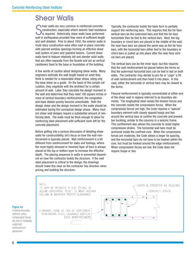
Flexural reinforcement is typically concentrated at either endof the shear wall in regions referred to as boundary ele-ments. The longitudinal steel resists the tension forces andthe concrete resists the compression forces. When thecompression forces are high, the Code requires a “special”boundary element with closely spaced hoops and tiesaround the vertical bars to confine the concrete and preventbar buckling, similar to the columns in a seismic frame.This confinement also allows the concrete to resist highercompressive strains. The horizontal wall bars must beanchored inside the confined core. When the compressionforces are moderate, the Code allows a larger tie spacing,and the horizontal bars do not have to be hooked within thecore, but must be hooked around the edge reinforcement.When compression forces are low, the Code does notrequire hoops or ties.
Figure 4aA typical boundary element, whencompression forces are low to moderate;outermost reinforcement placement.
6
Concrete Reinforcing Steel Institute

Figs. 4a and 4b show typical boundary elements when thecompression forces are low to moderate. In Fig. 4a the typi-cal vertical bars are placed as the outermost reinforcement.The typical vertical bars are discontinued at the boundaryelement, which is logical since the larger boundary elementbars effectively take their place. The horizontal bars endwith a standard hook engaging the vertical edgereinforcement.
Fig. 4b shows three rows of longitudinal reinforcement inthe boundary element. Note that for a clear spacing of 4inches between the longitudinal bars, the wall must be 16 to18 inches thick. Clearance is also needed for both lap andmechanical splices. The Code allows closer bar spacing, butconsidering the realities of splicing, a clear spacing of 4inches is desirable. Engineers sometimes use this type ofdetail in walls that are 10 or 12 inches thick. It is mucheasier for us to draw the little dots representing the bars inthe boundary elements than it is to place those large barswith such tight congestion. Note that if we detail the typicalhorizontal bars as the outer layers of bars, we can place thevertical boundary bars in the same plane as the typical verti-cal bars; we thus pick up an extra inch or so for our bound-ary bar placement.
Figs. 4c, 4d and 4e (shown on page 8) reflect typical “spe-cial” boundary elements. As noted before, the Code requiresthat horizontal bars be anchored in the confined core. Thisis typically done by hooking the bars into the confined corewith a standard 90° or 180° hook as shown in Fig. 4c.Headed reinforcing bars could be used if there was severecongestion. Typically, the boundary element cages areassembled at the fabrication shop, delivered to the construc-tion site, then hoisted into place. The typical horizontal barsare fished through the hoops and ties and anchored.Engineers sometimes specify that the horizontal bars behooked down into the cores with a 90° hook; however, it canbe difficult to install these bars without disassemblingnumerous ties. The bars can be hooked horizontally ratherthan down. This allows the typical horizontal bars to slideinto the core without having to dissemble ties. Another solu-tion is to use 180° hooks instead of 90° hooks. Since theout-to-out dimension of the hook is smaller for 180° hooks,the horizontal bars can be fished through a smaller width.Using 180° hooks, however, can make concrete placementand vibration more difficult.
Figure 4bA typical boundary element, when compression forces are low to moderate;additional longitudinal reinforcement.
7
Designer’s Responsibility
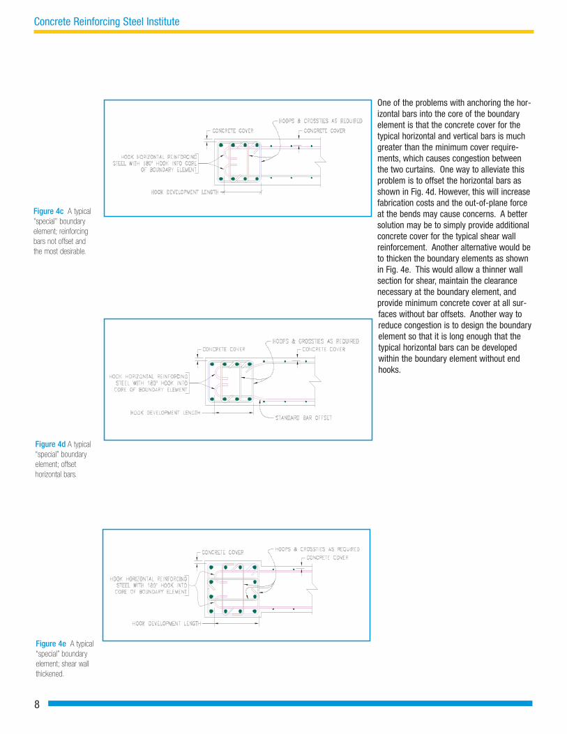
Figure 4d A typical“special” boundaryelement; offset horizontal bars.
One of the problems with anchoring the hor-izontal bars into the core of the boundaryelement is that the concrete cover for thetypical horizontal and vertical bars is muchgreater than the minimum cover require-ments, which causes congestion betweenthe two curtains. One way to alleviate thisproblem is to offset the horizontal bars asshown in Fig. 4d. However, this will increasefabrication costs and the out-of-plane forceat the bends may cause concerns. A bettersolution may be to simply provide additionalconcrete cover for the typical shear wallreinforcement. Another alternative would beto thicken the boundary elements as shownin Fig. 4e. This would allow a thinner wallsection for shear, maintain the clearancenecessary at the boundary element, andprovide minimum concrete cover at all sur-faces without bar offsets. Another way toreduce congestion is to design the boundaryelement so that it is long enough that thetypical horizontal bars can be developedwithin the boundary element without endhooks.
Figure 4c A typical"special" boundaryelement; reinforcingbars not offset andthe most desirable.
8
Concrete Reinforcing Steel Institute
Figure 4e A typical“special” boundaryelement; shear wallthickened.

Shear Walls With Coupling Beams
Shear walls with coupling beams are a very effectivemeans of providing lateral bracing for buildings sub-jected to earthquakes. This system is similar to the
exterior concrete wall with window openings discussed pre-viously. For simplicity, let’s consider a simple wall of twovertical piers connected at each floor with coupling beams.Fig. 5 illustrates this simple wall with seismic forces appliedhorizontally. If the coupling beams are fully effective andprovide complete coupling between the piers, the overturn-ing moments will be resisted by a vertical compressionforce in one wall pier (the pier to the right in Fig. 5) and ten-sion in the other pier. Under load reversals, the opposite willoccur. If we draw a freebody diagram through the couplingbeams, the sum of the vertical shears in the coupling beamswould equal the tension or compression force at the base ofthe wall from the overturning moment. The distribution oftotal vertical shear to the individual coupling beams can bedetermined by analysis. For preliminary analysis, considersome foundation rocking or base flexibility, and assumeequal shear or equal shear stress in each coupling beam forrough sizing. If the coupling beams are more flexible andprovide only partial coupling, there will be three base over-turning moments – one similar to the model alreadydescribed above and one at the base of each pier represent-ing the pier acting independently as a vertical cantileverwall. A computer analysis is necessary to determine thewall’s response, and it is a good idea to consider variablessuch as uncracked and cracked concrete sections and some
soil or foundation deformation beneath the base of the wall.Minor changes in cracked concrete properties or foundationdeformation can have a significant effect on computerresults; it is advisable to consider the range of possibleconditions.
The Code requires that coupling beams with a length-to-depth ratio less than two and shear stresses of 4 f’c orgreater be reinforced with groups of diagonal bars. TheCode permits diagonal reinforcement in beams with alength-to-depth ratio less than 4, but ratios greater than 3result in very flat diagonal bars that are not very effective.Diagonal reinforcement is not required if the couplingbeams do not affect building stability, which is usually anappropriate assumption for flexible coupling beams withlength-to-depth ratios greater than 3. Research followingthe 1964 Alaskan earthquake demonstrated the superiorperformance of this arrangement of reinforcement, com-pared to traditional beam reinforcement. While no onedebates the superior performance, some note the reinforc-ing bar congestion and placement issues that this arrange-ment of reinforcement creates. Placement can be greatlysimplified with proper planning and large enough sections.The wall should be at least 16 inches thick to allow place-ment of the reinforcing bars; 14 inches is the bare mini-mum.
Figure 5Coupled shearwall.showing typicalcoupling beamsrequiring diagonalreinforcement.
9
Designer’s Responsibility
sbb

Figure 6Elevation of couplingbeam with diagonalreinforcing bars. Notethat each diagonalstrut must consist ofat least 4 bars withclosely spaced ties asshown. Best to use afew vertical ties atcentral intersection.
Let’s consider a 16-inch thick wall with a diagonally rein-forced coupling beam similar to Fig. 6. Assume that eachdiagonal requires 4 - #9 (#29) bars and that there are twolayers of #9 (#29) longitudinal reinforcing bars at the edgeof the vertical piers. The #9 (#29) diagonal bars mustextend at least a full tension development length into thepier at each end. Each group of 4- #9 (#29) bars must alsobe enclosed in confinement reinforcement as would bespecified for column confinement in a special momentframe or the special boundary member of a shear wall. Thisamounts to something like #4 ties at 4 inches on center, asshown in Fig. 6. In the center where the diagonals overlap,the two groups of ties can either continue with some over-lapping, or one set of somewhat wider ties can be placedaround both groups of diagonal bars as shown in Fig. 6.
The key to getting the reinforcing bar layout to work is tospend a few minutes on a sketch like Fig. 7 to make surethat all of the bars will fit. Let’s look at Fig. 7 using roughsizes for bars and including an allowance for the bar defor-mations (which take up space). An interior wall needs ¾inch concrete cover; if the typical vertical and horizontalbars are #4 or #5 bars at 12 inches on center, the rein-forcement at each face including the cover will take upabout 2.25 inches. Adding another 1.25 inches for verticalwall boundary or trim bars gets us to 3.5 inches from eachface. The two layers of bars from each diagonal group addanother 2.5 inches and bring us to about 6 inches fromeach face. If our wall is 16 inches thick, we have 4 inchesavailable open in the middle of the wall for concrete place-
10
Concrete Reinforcing Steel Institute

Figure 8Placement of reinforcing bars for a coupling beam withdiagonal requirements.
Figure 7Cross section of a wall in Figure 6 showingrough bardimensions. Use asketch like this in your calculations to ensureyou make the wallthick enough to allowrebar and concrete tobe placed.
ment and vibration. (The ties around thediagonal reinforcement coincide with the ver-tical boundary element bars and thus do notrequire a dedicated space of their own.) A14-inch thick wall leaves only 2 inches clear;this invites concrete placement difficulties androck pockets at the surface. Note how easy itis to draw the sketch in Fig. 7; you can quick-ly ensure that you have provided a sectionthat is thick enough to place both reinforcingsteel and concrete. The authors use this typeof sketch routinely and find it guides themtowards a design that the contractor can buildwithout any great difficulties.
Fig. 8 shows reinforcing bars being placed fora coupling beam with diagonal reinforcement.It all goes well with some planning and a wallthat is thick enough to accommodate therequired reinforcement.
11
Designer’s Responsibility
HeadedReinforcingBars
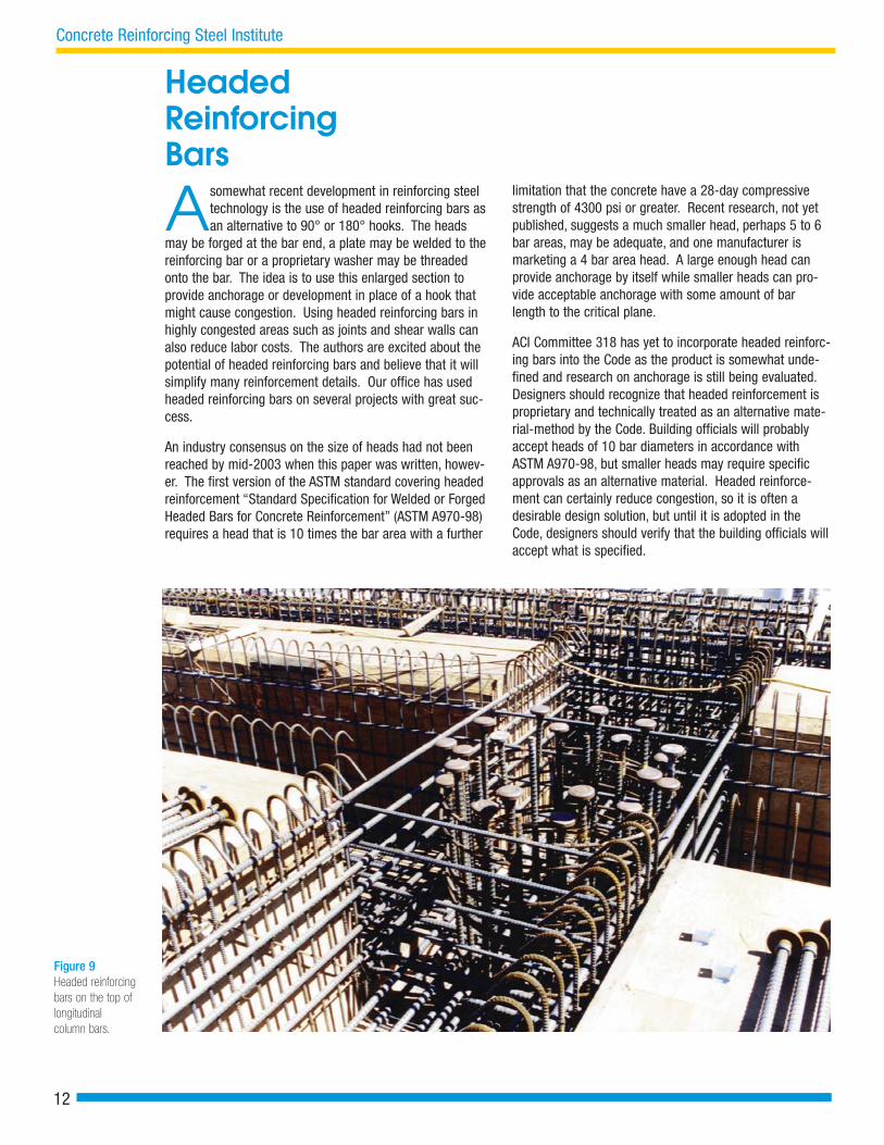
Asomewhat recent development in reinforcing steeltechnology is the use of headed reinforcing bars asan alternative to 90° or 180° hooks. The heads
may be forged at the bar end, a plate may be welded to thereinforcing bar or a proprietary washer may be threadedonto the bar. The idea is to use this enlarged section toprovide anchorage or development in place of a hook thatmight cause congestion. Using headed reinforcing bars inhighly congested areas such as joints and shear walls canalso reduce labor costs. The authors are excited about thepotential of headed reinforcing bars and believe that it willsimplify many reinforcement details. Our office has usedheaded reinforcing bars on several projects with great suc-cess.
An industry consensus on the size of heads had not beenreached by mid-2003 when this paper was written, howev-er. The first version of the ASTM standard covering headedreinforcement “Standard Specification for Welded or ForgedHeaded Bars for Concrete Reinforcement” (ASTM A970-98)requires a head that is 10 times the bar area with a further
limitation that the concrete have a 28-day compressivestrength of 4300 psi or greater. Recent research, not yetpublished, suggests a much smaller head, perhaps 5 to 6bar areas, may be adequate, and one manufacturer ismarketing a 4 bar area head. A large enough head canprovide anchorage by itself while smaller heads can pro-vide acceptable anchorage with some amount of barlength to the critical plane.
ACI Committee 318 has yet to incorporate headed reinforc-ing bars into the Code as the product is somewhat unde-fined and research on anchorage is still being evaluated.Designers should recognize that headed reinforcement isproprietary and technically treated as an alternative mate-rial-method by the Code. Building officials will probablyaccept heads of 10 bar diameters in accordance withASTM A970-98, but smaller heads may require specificapprovals as an alternative material. Headed reinforce-ment can certainly reduce congestion, so it is often adesirable design solution, but until it is adopted in theCode, designers should verify that the building officials willaccept what is specified.
Figure 9 Headed reinforcingbars on the top oflongitudinal column bars.
12
Concrete Reinforcing Steel Institute

13
Designer’s Responsibility
Soft metric designations for the sizes of reinforcing bars are shownthroughout this report. This approach follows current industry practice.In 1997, producers of reinforcing bars (the steel mills) began to phase
in the production of soft metric bars. The shift to exclusive production of softmetric bars has been essentially achieved. Virtually all reinforcing bars cur-rently produced in the USA are soft metric. The steel mills’ initiative of softmetric conversion enables the industry to furnish the same reinforcing barsto inch-pound construction projects as well as to metric construction proj-ects, and eliminates the need for the steel mills and fabricators to maintain adual inventory.
The sizes of soft metric reinforcing bars are physically the same as the cor-responding sizes of inch-pound bars. Soft metric bar sizes, which are des-ignated #10, #13, #16, and so on, correspond to inch-pound bar sizes #3, #4,#5, and so on. The table below shows the one-to-one correspondence of thesoft metric bar sizes to the inch-pound bar sizes. More information aboutsoft metric reinforcing bars is given in Engineering Data Report No. 42,“Using Soft Metric Reinforcing Bars in Non-Metric Construction Projects”.EDR No. 42 can be found on CRSI's Website at www.crsi.org.
Notes on Soft Metric Reinforcing Bars
Soft MetricBar Sizes vs.Inch-PoundBar Sizes
Designers should also check availability andlead time. There are currently a limitednumber of suppliers in the U.S., and mostreinforcing steel fabricators need to specialorder headed reinforcing bars. If there arelikely to be changes and modifications toanchorage details during construction,obtaining the required reinforcement on shortnotice may be a concern. Designers in seis-mic regions should be aware that headedreinforcement is intended for tension devel-opment; if stress reversals cause compres-sion in headed reinforcement near a surfaceparallel to the head, the concrete betweenthe head and the surface may pop out.
Fig. 9 illustrates using headed reinforcingbars on the top of longitudinal column bars.The heads were staggered slightly to avoidcreating a weakened plane. Imagine thecongestion that would have resulted if all ofthese bars were hooked. For reasons similarto the tank and retaining wall base discussedin the following section, proper design wouldrequire that the bars be hooked inward todevelop the moment strength of the column.

T-Configured Joints: Beam-Column and Wall-Footings
T-configured joints are common in structural design, yetengineers often do not design them correctly. Let’sconsider beam-column joints. Figure 3b illustrates an
exterior beam-column joint in a seismic resisting frame;since there is only a beam on one side of the column, wehave a T-configuration. Most engineers know they shouldhook the beam bars towards the center of the beam. Thisallows the beam bars in tension to impart diagonal com-pression from the radius of the hooks to close the internalforces within the joint. ACI 318-02 includes a new AppendixA for strut and tie models, which are an excellent way tounderstand the stress flow through such a joint. Let’s nowlook at a column-to-continuous roof beam, another T-config-ured joint. Without thinking of the internal joint stress flow,many engineers will hook the column bars out away fromthe center of the column with the thought that it will be eas-ier to place concrete down into the column. This is probablytrue but the joint cannot develop the flexural strength of thecolumn that may be needed in frames resisting lateralforces.
A similar condition exists at the base of a retaining wall ortank wall that is resisting significant bending moments.Let’s consider the wall-to-base slab detail in Fig. 10a. Thewall resists lateral fluid or soil pressure as a cantilever witha large base moment. A basement wall supported by a floorat the top also has large base moments. Likewise, a
Figure 10aRetaining orBasement Wall tobase slab detail.
circular tank wall that is designed allowing horizontal hooptension to resist the fluid pressure works fine but, therestraint of the base slab also results in a significantmoment at the base slab.
Should the vertical wall reinforcing bars be hooked in or outat the base slab in these cases? Many engineers and mostcontractors would hook the bars out to avoid congestion.This is wrong. A base slab detail with bars hooked out can-not develop the total moment in the wall. Research inSweden many years ago showed that a T-joint with wall andbase slab of about equal thickness, with wall bars hookedout as seen in Fig. 10b, can only resist about 40% of thewall moment. The joint develops diagonal shear cracks andeventually fails. The authors have observed a similar situa-tion where the cantilever wall of an open rectangular aque-duct resisting its internal water pressure deflected out sev-eral inches and leaked through the failed base joint. Thecracks and failure surface were similar to those in theSwedish tests.
Think of the wall as similar to the beam in a specialmoment resisting frame at an exterior column. For thatT-joint, we know we must hook the top and bottom beambars towards the center of the joint to make the joint per-form properly. It is the same for the wall base joint, as
14
Concrete Reinforcing Steel Institute
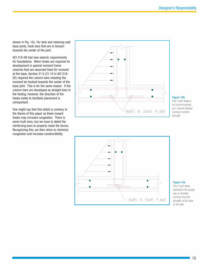
Figure 10bThis T-joint detail isnot recommended,as it cannot developnominal momentstrength.
Figure 10cThis T-joint detail represents the properway to develop nominal momentstrength at the baseof the wall.
shown in Fig. 10c. For tank and retaining wallbase joints, hook bars that are in tensiontowards the center of the joint.
ACI 318-99 had new seismic requirementsfor foundations. When hooks are required fordevelopment in special moment framecolumns that are assumed fixed for momentat the base, Section 21.8 (21.10 in ACI 318-02) required the column bars resisting themoment be hooked towards the center of thebase joint. This is for the same reason. If thecolumn bars are developed as straight bars inthe footing, however, the direction of thehooks solely to facilitate placement isunimportant.
One might say that this detail is contrary tothe theme of this paper as these inwardhooks may increase congestion. There issome truth here, but we have to detail thereinforcing bars to properly resist the forces.Recognizing this, we then strive to minimizecongestion and increase constructibility.
15
Designer’s Responsibility

Slabs On Ground
Slabs on ground are slightly different. Typically, theproblem is not avoiding congestion but achieving aslab that does not crack excessively. It is common for
designers to consider a slab on ground as nonstructural,which they often are, and simply specify a light welded wirefabric for reinforcement. Workers must walk on the smalldiameter welded wire fabric to place the concrete; testsafter the fact almost always show the welded wire fabric atthe bottom of the slab except very close to the supports.Having the workers pull up the fabric with claw hammers asthey finish the concrete never seems to work. The authorsbelieve it is better to reinforce slabs on ground with #4(#13)bars at perhaps 18 inches on center, 1 to 1.5 inches downfrom the top of the slab. Having this reinforcement near thetop surface of the slab controls cracking and the spacing islarge enough for the workers’ boots to go between barswithout forcing them to the bottom. Also, the bars are stifferthan the welded wire fabric, which is advantageous in casethey get stepped on during concrete placement. Reinforcingsteel in slabs on ground will not be effective in controllingcracking unless it is properly located within the concrete.
Two other points to consider for slabs on ground: slabs onground often crack excessively because of restraint to nor-
mal slab shortening from the soil or from columns and foot-ings. The shrinkage and temperature reinforcement in ACI318 is based on unrestrained concrete shrinkage and short-ening. When a slab is restrained, two and one-half to threetimes this reinforcement is needed to control cracking. Slabcracks often cause performance issues and a single curtainof substantial reinforcing steel is a very minor cost for anybuilding. Controlling cracking in slabs on ground can makebuilding owners very pleased with your design abilities.
Finally, slabs on ground often require expansion anchors toanchor equipment, shelving, storage racks, etc. ACI 318-02contains new requirements for expansion anchors andanchor bolts. It requires that expansion anchor embedmentbe limited to two-thirds of the slab thickness. This is due toa concern that the anchor expansion might blow out the bot-tom of the slab; the researchers had actually proposed thatthe limit be half of the slab depth. A 6-inch thick slab onground will have a 4-inch anchor embedment limitation; a5-inch. thick slab with have a 3.5 inch limitation. Slabs inwarehouse structures may need to be thicker than manyhave traditionally designed.
16
Concrete Reinforcing Steel Institute
ConclusionsIn this paper, the authors have offered some suggestions to their fellow structural engineers on our obligation todesign and detail reinforced concrete structures so the contractor and reinforcing steel subcontractor can build themas easily and economically as possible. Most of these suggestions are common sense and simply require giving alittle thought to how the design will be built. It has been the authors’ experience that a well-detailed set of draw-ings, where these constructibility issues have been addressed, results in lower bid prices. Once you establish a rep-utation in this way, contractors will praise your drawings, consistently give your designs lower bid prices, and theword will spread, possibly bringing you new design commissions.
NOTICE TO READERSThis Bulletin is intended as a medium for free exchange of structural design ideas among practicing Engineers. THe ideas so expressed are the authors’.Publication does not constitute endorsement by CRSI except as a meriting serious consideration. Readers are encouraged to submit discussions which maycorroborate, contradict, limit expand, or improve application of the original papers. Submit discussions to: David P. Gustafson, Technical Director, ConcreteReinforcing Steel Institute, 933 N. Plum Grove Road, Schaumburg, IL 60173
Funding for the production of this CRSI Structural Bulletin was provided by the California Field Iron Workers Administrative Trust.A Union Trust Fund.