The Design of High Reliability Magnetic Bearing Systems ...
12
Proceedings of the HTR 2014 Weihai, China, October 27-31, 2014 Paper HTR2014-X-XXX The Design of High Reliability Magnetic Bearing Systems for Helium Cooled Reactor Machinery M. Swann, N. Davies 1 , R. Gao 2 , Z. Guo 2 , R. Jayawant 1 , R. Leung 1 , R. Shultz 1 Waukesha Magnetic Bearings 20 Technology Way, West Greenwich, RI 02817 USA phone: +1 401 385 3703, [email protected] 1 Waukesha Magnetic Bearings, Unit K Downlands Business Park, Lyons Way, Worthing, W. Sussex BN14 9LA, UK 2 Waukesha Magnetic Bearings, No. 11 Wei Wen Road, Suzhou Industrial Park, P R China 215122 Abstract – The requirements for magnetic bearing equipped machinery used in high temperature, helium cooled, graphite moderated reactor applications present a set of design considerations that are unlike most other applications of magnetic bearing technology in large industrial rotating equipment, for example as used in the oil and gas or other power generation applications. In particular, the bearings are typically immersed directly in the process gas in order to take advantage of the design simplicity that comes about from the elimination of ancillary lubrication and cooling systems for bearings and seals. Such duty means that the bearings will usually see high temperatures and pressures in service and will also typically be subject to graphite particulate and attendant radioactive contamination over time. In addition, unlike most industrial applications, seismic loading events become of paramount importance for the magnetic bearings system, both for actuators and controls. The auxiliary bearing design requirements, in particular, become especially demanding when one considers that the whole mechanical structure of the magnetic bearing system is located inside an inaccessible pressure vessel that should be rarely, if ever, disassembled over the service life of the power plant. Lastly, many machinery designs for gas cooled nuclear power plants utilize vertical orientation. This circumstance presents its own unique requirements for the machinery dynamics and bearing loads. Based on the authors’ experience with machine design and supply on several helium cooled reactor projects including Ft. St. Vrain (US), GT-MHR (Russia), PBMR (South Africa), GTHTR (Japan), and most recently HTR-PM (China), this paper addresses many of the design considerations for such machinery and how the application of magnetic bearings directly affects machinery reliability and availability, operability, and maintainability. Remote inspection and diagnostics are a key focus of this paper. INTRODUCTION The magnetic bearing industry has evolved to serve a wide range of industrial applications from high volume vacuum pumps for the semiconductor industry with relatively standardized specifications to some highly specialized applications in the oil & gas sector with very demanding specifications. Application to gas cooled reactor machinery is more akin to the latter but with some very unique requirements for reliability and safety. The specification and design of these bearings accordingly becomes significant to the nuclear power plant system design basis. In particular, remote observability and diagnostics becomes of vital importance in order to gain long term reliability and availability while completely
Transcript of The Design of High Reliability Magnetic Bearing Systems ...

Proceedings of the HTR 2014 Weihai, China, October 27-31, 2014
Paper HTR2014-X-XXX
The Design of High Reliability Magnetic Bearing Systems
for Helium Cooled Reactor Machinery
M. Swann, N. Davies1, R. Gao2, Z. Guo2, R. Jayawant1, R. Leung1, R. Shultz1
Waukesha Magnetic Bearings
20 Technology Way, West Greenwich, RI 02817 USA
phone: +1 401 385 3703, [email protected]
1 Waukesha Magnetic Bearings, Unit K Downlands Business Park, Lyons Way,
Worthing, W. Sussex BN14 9LA, UK
2 Waukesha Magnetic Bearings, No. 11 Wei Wen Road, Suzhou Industrial Park, P R
China 215122
Abstract – The requirements for magnetic bearing equipped machinery used in
high temperature, helium cooled, graphite moderated reactor applications present a
set of design considerations that are unlike most other applications of magnetic
bearing technology in large industrial rotating equipment, for example as used in
the oil and gas or other power generation applications. In particular, the bearings
are typically immersed directly in the process gas in order to take advantage of the
design simplicity that comes about from the elimination of ancillary lubrication and
cooling systems for bearings and seals. Such duty means that the bearings will
usually see high temperatures and pressures in service and will also typically be
subject to graphite particulate and attendant radioactive contamination over time.
In addition, unlike most industrial applications, seismic loading events become of
paramount importance for the magnetic bearings system, both for actuators and
controls. The auxiliary bearing design requirements, in particular, become
especially demanding when one considers that the whole mechanical structure of the
magnetic bearing system is located inside an inaccessible pressure vessel that
should be rarely, if ever, disassembled over the service life of the power plant.
Lastly, many machinery designs for gas cooled nuclear power plants utilize vertical
orientation. This circumstance presents its own unique requirements for the
machinery dynamics and bearing loads.
Based on the authors’ experience with machine design and supply on several helium
cooled reactor projects including Ft. St. Vrain (US), GT-MHR (Russia), PBMR
(South Africa), GTHTR (Japan), and most recently HTR-PM (China), this paper
addresses many of the design considerations for such machinery and how the
application of magnetic bearings directly affects machinery reliability and
availability, operability, and maintainability. Remote inspection and diagnostics
are a key focus of this paper.
INTRODUCTION
The magnetic bearing industry has evolved to
serve a wide range of industrial applications from
high volume vacuum pumps for the semiconductor
industry with relatively standardized specifications
to some highly specialized applications in the oil &
gas sector with very demanding specifications.
Application to gas cooled reactor machinery is
more akin to the latter but with some very unique
requirements for reliability and safety. The
specification and design of these bearings
accordingly becomes significant to the nuclear
power plant system design basis. In particular,
remote observability and diagnostics becomes of
vital importance in order to gain long term
reliability and availability while completely

Proceedings of the HTR 2014 Weihai, China, October 27-31, 2014
Paper HTR2014-X-XXX
eliminating any maintenance requirements for
many years.
Like many aspects of nuclear power plant
design, certain technology choices have an
important effect on the overall viability of the
power plant. The bearings for the machinery may
have significant influence on the overall plant
efficiency, maintainability and cost of maintenance,
reliability and availability, personnel radiation
exposure, and plant safety. Of course,
thermodynamic and practical machinery
considerations will largely govern some of the
primary machine decisions like single vs. multi-
shaft designs, and horizontal vs. vertical orientation.
Flow losses in the piping connected to the reactor
are an example of the thermodynamic
considerations; building support structure is also
important in the consideration of the machinery
orientation. Another primary consideration is
whether the machine design will be hermetic or
non-hermetic using dynamic shaft seals, employing
external buffer gas supplies, internal or external
cooling provisions or not. Implicit in these
decisions is the choice between ‘wet’ and ‘dry’
bearings that affect whether there will be an
external lubrication system or not. In turn, this
choice impacts considerations of the fire protection
provisions.
Active magnetic bearings (AMBs) have been
employed in all recent helium cooled reactor
designs as the only mature dry bearing technology
after problems with wet bearings contributed
directly with operating difficulties at the early AVR
and THTR helium reactors in Germany where oil
lubrication was used, as well as the HTGR at Ft. St.
Vrain in the United States where water lubricated
bearings were used. This history dates back thirty
years. Speaking of the HTGR at Ft. St. Vrain after a
series of at least 14 failures of the circulator
systems leading to several lubricant ingress events
and large down times“, Brey [1] concluded that
“successful circulator operation requires nearly
flawless performance of a complex circulator
auxiliary system which includes … valves and
instruments while supporting components such as
pumps, compressors, heat exchangers, and
vessels, …overall plant performance has been
impaired”. Speaking of the AVR after a turbine oil
fire, Ziermann and Engel [2], reported that “it must
be emphasized that the reliability of a primary gas
circulator in gas cooled reactors absolutely
depends on the effectiveness of the buffer helium
system (used to keep oil confined to the oil
reservoirs)”. With regard to the THTR, Glahe and
Stolzl [3], stated following an incident where
radioactive gas escaped after graphite fuel balls
stuck in the fuel inlet “that further development
work on the circulators is currently being continued
for the only reason that active magnetic bearings
permit vertical arrangement of the
circulators…without requiring the operation of an
extremely complicated and expensive oil
system...The costs of the oil and gas seal systems
are about twice as high as the costs of the (six)
circulators themselves”. All three of these reactors
were prematurely shutdown and decommissioned in
large part because of these and related issues that
can be traced directly to inadequate design
decisions including the bearings.
Moreover, as indicated in [3], the precedent for
equipping all such helium reactor machinery with
magnetic bearings became well established and has
led all the recent helium cooled reactor designs to
consider and specify magnetic bearings for the
primary coolant loop machinery. This population
includes the direct cycle designs for PBMR in
South Africa, GT-MHR in Russia, GT HTR in
Japan, and the indirect cycle design for HTR-PM
by INET in China. The magnetic bearing systems
of these designs must provide acceptable levels of
reliability and availability while minimizing
maintenance. This is accomplished through proper
design which includes the exploitation of provisions
for remote observability and diagnostics.
Figures 1, 2, and 3 contained herein,
respectively show the machine design arrangements
with magnetic bearings for the PBMR fuel ball
blower, the HTR-PM fuel ball blower, and the
HTR-PM circulator.
Fig. 1: PBMR Fuel Ball Blower.
Proceedings of the HTR 2014 Weihai, China, October 27-31, 2014
Paper HTR2014-X-XXX
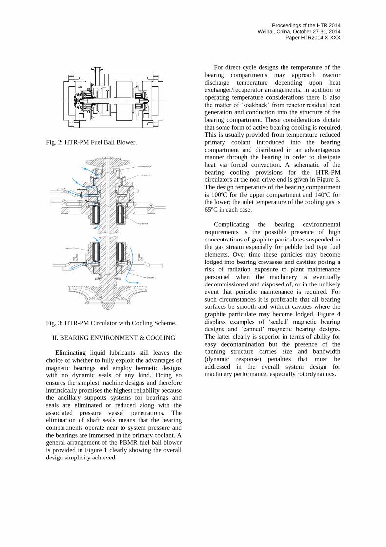
Fig. 2: HTR-PM Fuel Ball Blower.
Fig. 3: HTR-PM Circulator with Cooling Scheme.
II. BEARING ENVIRONMENT & COOLING
Eliminating liquid lubricants still leaves the
choice of whether to fully exploit the advantages of
magnetic bearings and employ hermetic designs
with no dynamic seals of any kind. Doing so
ensures the simplest machine designs and therefore
intrinsically promises the highest reliability because
the ancillary supports systems for bearings and
seals are eliminated or reduced along with the
associated pressure vessel penetrations. The
elimination of shaft seals means that the bearing
compartments operate near to system pressure and
the bearings are immersed in the primary coolant. A
general arrangement of the PBMR fuel ball blower
is provided in Figure 1 clearly showing the overall
design simplicity achieved.
For direct cycle designs the temperature of the
bearing compartments may approach reactor
discharge temperature depending upon heat
exchanger/recuperator arrangements. In addition to
operating temperature considerations there is also
the matter of ‘soakback’ from reactor residual heat
generation and conduction into the structure of the
bearing compartment. These considerations dictate
that some form of active bearing cooling is required.
This is usually provided from temperature reduced
primary coolant introduced into the bearing
compartment and distributed in an advantageous
manner through the bearing in order to dissipate
heat via forced convection. A schematic of the
bearing cooling provisions for the HTR-PM
circulators at the non-drive end is given in Figure 3.
The design temperature of the bearing compartment
is 100ºC for the upper compartment and 140ºC for
the lower; the inlet temperature of the cooling gas is
65ºC in each case.
Complicating the bearing environmental
requirements is the possible presence of high
concentrations of graphite particulates suspended in
the gas stream especially for pebble bed type fuel
elements. Over time these particles may become
lodged into bearing crevasses and cavities posing a
risk of radiation exposure to plant maintenance
personnel when the machinery is eventually
decommissioned and disposed of, or in the unlikely
event that periodic maintenance is required. For
such circumstances it is preferable that all bearing
surfaces be smooth and without cavities where the
graphite particulate may become lodged. Figure 4
displays examples of ‘sealed’ magnetic bearing
designs and ‘canned’ magnetic bearing designs.
The latter clearly is superior in terms of ability for
easy decontamination but the presence of the
canning structure carries size and bandwidth
(dynamic response) penalties that must be
addressed in the overall system design for
machinery performance, especially rotordynamics.

Proceedings of the HTR 2014 Weihai, China, October 27-31, 2014
Paper HTR2014-X-XXX
Fig. 4: Canned (top) and sealed (bottom) magnetic
bearings; radial bearings (left), axial bearings
(right).
Graphite particulate also may have a large
impact on the operation and reliability of auxiliary
bearings which, depending on their design, may be
much more prone to adverse effects than the
magnetic bearings because the auxiliary bearings
are intrinsically contact type bearings whereas the
magnetic bearings are not. For this reason alone,
bushing type auxiliary bearings, Figure 5, are
preferred with few or no moving parts that may
become fouled, thereby leading to a compromised
operating ability with the buildup of contaminants
over time. Obviously, this becomes more
problematic where the particles are relatively large
in size, have a high hardness and exist in high
concentrations. A fine dispersion of soft graphite,
on the other hand, may be beneficial for lubrication
of the bearings.
Fig.5: Bushing style auxiliary bearing.
III. SEISMIC DESIGN CONSIDERATIONS
Unlike most other industrial applications,
seismic loading events become of paramount
importance for the magnetic bearings systems used
in high temperature gas cooled reactor applications.
This presents a set of design considerations for
magnetic bearing system actuators and their control
systems.
In general, the seismic events can be classified
as Operating Basis Earthquake (OBE, SL-1) and
Safe Shutdown Earthquake (SSE, SL-2), following
the commonly recognized standards by the
International Atomic Energy Agency (IAEA) and
Nuclear Regulatory Commission (NRC). All safety
‐ related equipment must prove its seismic
adequacy to withstand the effects of the earthquake
by ensuring the safe operation of machines under
design basis operating events (OBE, SL-1) and the
safe shutdown under the maximum design
earthquake events (SSE, SL-2).
One of the indicators to define the seismic
conditions for the design basis operating event and
safe shutdown is by the magnitudes of Peak Ground
Accelerations (PGA). Typically, the maximum
values of PGA’s magnitudes in X, Y, Z coordinates
can be defined as the seismic conditions
corresponding to the two events.
The importance of the response spectrum
approach in the seismic design of safety related
equipments is well known to earthquake design
engineers. The response spectrum would show the
influence of various parameters such as site
geographical conditions and the level of peak
ground accelerations. The seismic design response
spectrum is often obtained by a statistical analysis
of a large number of actual earthquake ground
motions and response spectra. For example, the
studies completed in [4], [5], and [6] provided a
foundation for the AEC Design Response Spectra
in its Regulatory Guide 1.60 (1973), which was also
adopted by ASME in [8] and IEEE in [9]. The
response spectrum describing the local site
geographical conditions becomes the design basis
of machines for its application.
When considering the design of magnetic
bearing systems for nuclear power reactors,
distinction should be made between large
earthquake loads and other short term loading
events. In the event of complete failure of the
magnetic bearing system, a signal is generated by

Proceedings of the HTR 2014 Weihai, China, October 27-31, 2014
Paper HTR2014-X-XXX
the control system requesting a system shutdown.
In contrast, in the event of certain magnetic bearing
system transient overloads without magnetic
bearing system failure, the auxiliary bearings accept
the momentary overload and allow the magnetic
bearings to regain control of the rotor. Normal
operation then continues. The nature and duration
of these overloads needs to be defined. The OBE or
SL-1 is one such event but SSE or SL-2 is not. In
the case of a SL-2 event, the rotor may experience a
complete rundown on the auxiliary bearings as part
of the controlled shutdown sequence.
The control logic for seismic loading
considerations can be summarized as
During a SL-1 event the rotor may
momentarily contact the auxiliary bearings.
The magnetic bearing system will not initiate a
shutdown during a SL-1 event.
During a SL-2 event the rotor may rundown on
the auxiliary bearings. The magnetic bearing
system will undergo a controlled shutdown
during a SL-2 event.
Seismic qualified design of the magnetic
bearing systems is comprised of the relevant static
and dynamic analyses including the transient
simulation analysis when the rotor is supported on
magnetic bearings and/or auxiliary bearings during
seismic as well as other short term overloading
events.
IV. VERTICAL MACHINERY ORIENTATION
Reactor and plant layout considerations often
demonstrate the advantages of vertical orientation
of the rotating machinery, e.g. the helium circulator
for HTR-PM in Figure 3. Vertically oriented
machinery presents special considerations.
With horizontal machines the primary radial
magnetic bearing load is often the gravity load.
Obviously, the gravity load for the radial bearings
of a vertical machine is zero, but the sizing of the
radial magnetic bearings must still be carefully
considered. With the vertical orientation, the
loading for the radial bearings includes the dynamic
load due to imbalance, side loads induced by
aerodynamic effects, and dynamic loads from
environmental effects, such as seismic loading. The
radial bearing size is determined based on these
loads, as well as the stiffness and damping
characteristics required for the application. The
required bearing stiffness to control the amplitude
of rotor motion often governs the bearing sizing.
For rotor vertical orientation, the axial magnetic
bearing sizing must accommodate the gravity load
and other loading effects. These other loading
effects include pressure loads, loads induced by
machine aerodynamics, and loads induced by
environmental effects, such as seismic loading.
With regard to the auxiliary bearings, the
vertical orientation changes the sizing criteria for
the radial and axial bearings. The radial auxiliary
bearing sizing must accommodate whirl loads,
aerodynamic side loads, and dynamic loads due to
environmental vibrations, i.e. excitation of the
machine support structure including seismic loads.
The worst case seismic loading will cause
overloading of the magnetic bearings, and the
resulting contact with the auxiliary bearing will be
an impact type loading; this often becomes a
significant design criterion.
The axial auxiliary bearings loading consists of
the gravity load, pressure and aerodynamic loads,
and loads induced by environmental effects, in this
case the seismic loading. During each auxiliary
bearing full landing event, the drop through the
working air gap clearance of the bearing induces an
impact load. Also, the worst case seismic loading
will cause overloading of the magnetic bearings,
and the resulting contact with the auxiliary bearing
will be an impact type loading. Again, this often
becomes a significant design criterion for a
successful auxiliary bearing design.
Unlike fluid film bearings, vertical rotor
orientation does not cause any significant
rotordynamic stability concerns with magnetic
bearings. Whirl instability may occur in fluid film
bearings because of the absence of a gravity load
that provides a consistent eccentricity in the fluid
film bearing. This problem does not occur at all
with magnetic bearings: the linear rotordynamic
characteristic of the magnetic bearing is not
dependent on the static loading condition. Even
with a static loading of zero, the magnetic bearing
maintains a stable operating characteristic.
V. AMB SYSTEM NUCLEAR QUALIFICATION
The mechanical components of the magnetic
bearing system are qualified for seismic service by
stress and deflection analyses of the mechanical
components to establish that the integrity of the
design is maintained during the seismic events. This
is often done with a static equivalent analysis
method, a well recognized method for qualifying

Proceedings of the HTR 2014 Weihai, China, October 27-31, 2014
Paper HTR2014-X-XXX
mechanical components for seismic and shock
environments.
Considering that the magnetic bearing control
cabinet is placed away from the machine, the
challenging issue for nuclear qualification of this
unit is its performance during the seismic events.
The control cabinet should maintain structural
integrity and properly perform its specified
functions before, during and after the design basis
operating event and the safe shutdown event. This
requirement may involve special mounting design
for the control cabinet, to attenuate the transmission
of seismic loading from the ground to the
equipment. The seismic qualification test of
controls shall be then carried out to demonstrate the
seismic mounting design is fit for purpose. The
testing of the equipment should be implemented in
compliance with [9].
VI. RELIABILITY, AVAILABILITY & LIFE
VI.A General Reliability Considerations
Few applications of magnetic bearings demand
more system level reliability than nuclear power. A
single failure mode in the magnetic bearing system
has the potential to take down the entire plant
leading to a loss in power production. As in other
systems, there are two fundamental approaches to
the attainment of high reliability: (1) ultra high
reliability of individual components, especially
those that comprise a single point failure, and (2)
built in redundancy that may be implemented either
by manual or automatic means. The choice between
these two approaches is usually governed by
considerations of allowable failure rates vs. the
costs involved in implementation.
Fortunately, the intrinsic reliability of the
components that comprise a magnetic bearing
system is high and the factors limiting the service
life of these same components, especially those
located inside the machine structure and pressure
vessels are few. With proper design, long lives may
be attained without any appreciable attention by
plant operators. Obviously, the environmental
conditions discussed above like bearing
compartment pressure and temperature may have an
effect on service life thereby underlining the
importance of good design of the components
themselves, the materials used and the cooling
provisions. Exposure to long periods of immersion
in helium by bearing designs of the authors’
company (e.g. the PBMR fuel ball blower in Figure
1) has shown no quantifiable degradation in the
condition of these components as long as
fundamental protection from the environment is
afforded. Notably, this includes the proper selection
of electrical resins for the impregnation of the
bearing windings and position sensors for the high
pressure, high temperature helium environment.
Some of the designs for large turbine generators
of direct cycle plants (e.g. PBMR) utilized fully
redundant AMB systems with fully redundant
controls serving magnet structures in the machines
that are also fully redundant. However, for compact
machine design with good rotordynamic behavior,
non-redundant magnet cores (or bearing “magnets”)
will generally be utilized with a level of redundancy
applied to the position, temperature, and speed
sensors. Position sensors may employ voting (e.g.,
2 out of 3 logic) or, more simply, two complete
sensor systems with the capability to manually
switch over to the inactive sensor from the control
cabinet. There is an obvious impact here on the
number of electrical penetrations required as
described below. In addition, unless the position
sensors are collocated, there is a need to change the
servo control software to accommodate the axial
change in location of the redundant sensor along the
rotor length.
The selection of auxiliary bearing materials and
associated lubricants has a fundamental effect on
their long term life and operability. The inertness
and lack of any oxygen or water in the helium
environment, coupled with the potential presence of
hard particulates in the gas, present a significant
challenge to the lubrication of the auxiliary
bearings rendering most designs employing rolling
elements to be challenged by the long term
exposure and the need to provide a low risk of
failure when their operability is required following
a machine event. This indicates that contacting
surfaces will usually need to be protected by dry
lubricated bushings and thrust washers that have
been specially selected for the inert and difficult
environment.
For power plant equipment that is considered as
safety related, an Equipment Qualification (EQ)
program is usually employed. A key aspect of EQ
as described in [10] is the aging to be simulated
before the demonstration of the capability to
perform the safety function at the end of the
qualified equipment life. This aging depends on the
environmental service conditions (normal and
accident) and on the operational cycles and points

Proceedings of the HTR 2014 Weihai, China, October 27-31, 2014
Paper HTR2014-X-XXX
to challenges particularly with auxiliary bearings
during the OBE because of fouling and
contamination issues that may accrue over time.
VI.B AMB Controller Reliability Considerations
The use of magnetic bearing controllers that
provide quick recovery from a single point failure
may be of the ‘A+B’ type where two complete and
independent control systems are utilized, or ‘n+1’
where one additional “channel” is provided that
may be brought into operation to replace an
operating channel after fault detection. A channel is
usually associated with one of the control axes of
the machine. For example, a machine with two
radial bearings and one axial bearing will have five
channels controlling five degrees of freedom of
motion: two for each radial bearing and one for the
axial bearing. The switch over to the redundant
controller or channel may be either automatic or
manual. The A+B arrangement has been used
reliably in several AMB applications. Automatic
switchover of the n+1 arrangement is also possible
but making this truly ‘bumpless’ without auxiliary
bearing contact is very challenging. Hence, where
redundancy is specified, A+B systems are usually
employed and the auxiliary bearing system must be
capable of accepting the extra duty of momentary
contact without inducing undesirable rotor behavior.
There are often some challenges here.
VI.C Reliability & Pressure Vessel Penetrator
Considerations
For both cost and reliability concerns, the
number of pressure vessel penetrations needs to be
minimized and there are special considerations for
the arrangement of penetrators used. Generally,
separate penetrators are employed for the electric
motor connections and the magnetic bearing
connections.
As an example, for the HTR-PM circulator
project, the wires for the magnetic bearings are
arranged to go through two penetrators. There is
one penetrator for the large cross section magnet
wires and another penetrator for the small cross
section sensor wires in each circulator. There are 28
pins in the bearing magnet wires penetrator with no
spare pins. There are no critical issues with the
allocation of pins. To minimize the amount of the
potential electromagnetic interference arising from
the electrical connection to the bearing magnet, the
two connections for a magnet are allocated adjacent
pins. This reduces the area enclosed by the wires
and hence the magnetic flux produced.
There are 164 pins in the sensor signal
penetrator for each HTR-PM circulator in Figure 3.
The count is high in order to satisfy redundancy
requirements. For the signal penetrator, noise is an
important factor and the allocation of pins is critical
for the performance of the bearing. These pins are
physically grouped into position sensor, speed
sensor, temperature sensor and flux sensor, in the
order of lowest to highest noise level. The
temperature sensor and flux sensor are located
adjacent to the magnet coil which is a very noisy
environment. Therefore, the temperature sensors
and flux sensors are in an adjacent area in the
penetrator. The position sensor pins are at the far
end of the penetrator relative to the noisy
temperature and flux sensors. Spare penetrator
pins are allocated between sensor groups to provide
extra spacing between noisy and clean signals. Both
sets of redundant sensors are routed through the
penetrator so that if the need arises, a swap over of
connections can be done in a safe, non-radioactive
area.
The penetrators for the HTR-PM fuel ball
blower, Figure 2, are for individual bearing parts.
This arrangement allows different parts of the
bearing to be disassembled without removing wires
from the penetrator. For the impeller end of the
machine, there are three penetrators. One penetrator
is for the radial magnet connections. The second
penetrator is for the axial magnet and flux sensors
connections. The third penetrator is for the position,
speed and temperature sensors connections.
Similarly, on the motor end of the machine, there
are penetrators for the bearing magnets and the
three sensor group connections.
VI.D Remote Inspection and Diagnostics of
Magnetic Bearing Machine Components
As indicated earlier, condition monitoring of
magnetic bearing supported equipment is of
particular concern when the equipment is located
within the primary coolant loop inside a pressure
vessel. In this case the costs associated with a
visual inspection of the equipment are significant
and such magnetic bearing supported equipment
may be equipped with a diversity of diagnostic
capability to assess and predict the ability of the
machine to continue in operation. Even where
machinery is outside of the primary loop, condition
monitoring can help ensure that unplanned
downtime is eliminated.
Except for auxiliary bearings, the service life of
magnetic bearing components is very long, often

Proceedings of the HTR 2014 Weihai, China, October 27-31, 2014
Paper HTR2014-X-XXX
measured in decades, and the assessment of their
condition is readily accomplished. The electrical
windings of the magnetic bearing themselves will
have a service life dictated by the quality of the
electrical insulation system design and
implementation. The commonality of these
windings with those that have been used in motors
and generators opens up the realm of standard
electrical tests that have been used in such
equipment for decades, e.g. megger, hi pot, and
surge testing techniques. Generally, the full
spectrum of these tests will require access to the
magnetic bearing controller side cable lead ends in
the safe, non-radioactive area where the controllers
are located.
The operation and maintenance of the rotor-
bearing systems for helium service is readily
assisted by using the innate intelligence of the
magnetic bearing system. This intelligence stems
partly from rotor position and vibration information
that is used to control the rotor with the
electromagnetic forces of the bearings. There is a
whole body of work demonstrating the usefulness
of vibration information in diagnosing rotating
machinery condition and this information is
available for display and monitoring from remote
via the magnetic bearing controller.
Vibration information is augmented from the
AMB controller by information related to the
bearing loads as well as fundamental information
regarding the rotor-bearing system stability. The
bearing load information is characterized via
bearing currents or bearing magnetic flux
measurements that may be viewed and analyzed
from remote. The rotor-bearing system stability
data is enabled via the ability to measure transfer
functions of rotor displacement for force (or voltage)
disturbances across a broad frequency band by
voltage signals injected into the controller from
remote using the controller internal spectrum
analyzer functionality. The API and ISO
specifications on magnetic bearings, [11] and [12],
respectively, recognize the significance of such
transfer functions. Mechanical bearings have no
comparable capabilities without a large amount of
added complex features and external
instrumentation. Third generation magnetic bearing
technology provides the capability for internal
spectrum analyzer functionality and remote
connection via TCP/IP thereby adding a whole new
dimension to the magnetic bearing system
measurement capability. This is particularly
relevant to gas cooled nuclear power plant
machinery. All of this bearing current, flux, and
transfer function information is available remotely
from the AMB controller in order to assist in
monitoring and diagnosing rotating machinery
condition.
As examples, a waterfall plot from a current
sensor with its frequency content taken in a
machine rundown is shown in Figure 6. Figure 7
shows elimination of the rotor response of a
machine at the rigid body mode from remote.
Figure 8 shows the before and after vibration
response of a machine following implementation of
the authors’ company vibration attenuation
algorithm from remote. These capabilities can be
used for initial commissioning and subsequent
maintenance troubleshooting. It can also be used to
retune the machine after many years of operation
where necessary. For example, changing impeller
clearances may cause a change in cross-coupled
impeller forces that start to degrade the stability of
the rotor. Figure 9 shows an example of a stability
plot before and after re-tuning. Increasing impeller
seal clearances are a significant indicator of
machine health and they may be measured by
changes in the rotor ‘plant’ with magnetic bearings.
The plots represented by Figures 6-9 and many
more are available from the magnetic bearing
controller.
Fig. 6: Waterfall plot of machine shutdown
showing bearing current frequency content.
Fig. 7: Remote tuning to eliminate machine
response at rigid body mode.
050
100150
200
-5
0
5
100
1
2
3
4
5
Frequency (Hertz)
Some sort of description
Time (seconds)
Mag.;
TH
- C
urr
ent
[A]
(0-p
k)

Proceedings of the HTR 2014 Weihai, China, October 27-31, 2014
Paper HTR2014-X-XXX
Fig. 8: Typical vibration attenuation algorithm
results.
Fig. 9: Nichols plot depicting relative rotor stability
before and after re-tuning from remote.
Where the data is accessible through a data
communications interface, then the data would
normally be captured by the plant data systems to
allow trending and correlation of bearing behavior
with the power plant operating conditions. In order
to facilitate the remote diagnostics and the
diagnostics by on site local personnel, the magnetic
bearing controller may be equipped with external
tools which allow automation of both routine and
complex tasks in both the commissioning phase and
when conducting diagnostics on an operational
machine for health monitoring purposes. The
authors’ company has given this type of tool
framework the name Automated Commissioning.
This capability requires appropriate training of
plant staff as well as the availability of the
necessary communication network infrastructure.
Automated Commissioning is a suite of
programs that automate the procedures followed by
a skilled magnetic bearing commissioning engineer.
These programs run on an external computer that
communicates with the magnetic bearing controller
via TCP-IP networking. This computer can be near
the machine or remote. By stepping a machinery
engineer through the commissioning process in a
structured sequence, Automated Commissioning
enables a magnetic bearing system to be brought
into operation without the presence of a magnetic
bearing specialist. Being computer driven,
Automated Commissioning is also faster compared
to existing hands on commissioning procedures,
and it collects and archives all necessary results,
providing a baseline for scheduled maintenance.
For the first machine of a new design using
magnetic bearings, tuning will be based on
rotordynamic analysis, and this tuning will need to
be verified by measurements on the real machine.
The System Dynamics tool automates the collection
and presentation of the performance data necessary
to verify this theoretical tuning. Since the data
collection can be controlled remotely, the specialist
engineers responsible for rotordynamic analysis and
design never need to visit the machine on site.
The System Dynamics tool also adjusts the
controller parameters automatically to achieve
predefined performance targets. The targets and
criteria are saved in configuration files so they can
be reused later in the lifecycle of this machine and
speed up the tuning of the magnetic bearing
controller. The tools use transfer function, spectrum
analysis and harmonic (order) analysis functions
built into the magnetic bearing controllers;
therefore, specialist test equipment is not required
to complete the tuning of the magnetic bearing.
Throughout the operating life of the machine,
with this added functionality the end users will have
the benefit of automated re-commissioning tasks
after maintenance, independent of the magnetic
bearing supplier or the machine builder.
Furthermore, the plant operator can schedule
routine measurements using the System Dynamics
tools to measure and detect long term degradation
in machine performance, and plan maintenance at
the most appropriate time. Such degradation can be
related to changes in the bearing vibration or
current measurements, or changes in the basic
rotor-bearing system stability as measured by
changes in the transfer function measurements.
VI.E Auxiliary Bearing Reliability and
Observability
Unlike the other internal magnetic bearing
system components, the auxiliary bearings are
expendable contact type devices and have finite
service lives. Full use of their service life, i.e.
-225 -180 -135-15
-10
-5
0
5
Nichols Chart
Open-Loop Phase (deg)
Open-L
oop G
ain
(dB
)
New Trans. Fn
new GM = 6.9 dB
new PM = 24 deg
PM = 14 deg
GM = 3.9 dB

Proceedings of the HTR 2014 Weihai, China, October 27-31, 2014
Paper HTR2014-X-XXX
failure, means there is no longer any ability to
provide further protection to the machine against
internal rub damage between rotating and stationary
components. Accordingly, auxiliary bearing failure
may be accompanied by damage to the magnetic
bearing system and/or internals of the rotating
machine and therefore must be avoided beforehand
in order to enable a replacement or take other
preventative measures. Remote observability is thus
very important.
The employment of bushings such as in Figure
5 where wear is the only real failure mode provides
a superior capability for remote observability of the
service condition because electronic clearance
checking, both laterally and axially, may be
performed using the magnetic bearing controller.
This may be done by commanding rotor traverses in
the bearing clearance while the rotor is levitated but
not rotating. These traverses may be along the
magnetic bearing control axes or preferably around
the full circumference of the bushing thereby
producing a complete profile of the bushing wear
patterns. Such checks should be performed after
any substantial contact event and before each restart
of the machine.
The importance of such checks has been
recognized in the magnetic bearing standards, [11]
and [12]. For example, the auxiliary bearing
language in [11] requires a means to detect
auxiliary bearing contacts during machine operation
and necessitates that the “operability” or service
condition of the auxiliary bearings be observable
without machine disassembly. Obviously, the
impracticality of accessibility of machinery
components inside a nuclear pressure vessel
underscores the importance of such remote
observability.
The way in which different auxiliary bearing
designs fail is important in the determination of the
risk of premature failure as well as the capability
for remote assessment of the service life. Because
of the uncertainty of the auxiliary bearing service
life, and its shortness in terms of the ability to
withstand more than a few full speed drop downs
(or “landings”), the best way to address bearing
failures is through statistical analysis that provides
quantitative insight into the probability of obtaining
the full design life. The Weibull statistical
distribution is one means to accomplish this: it is
the most widely recognized and employed tool by
which to quantify life data and predict component
reliability, [13]. The Weibull β shape or slope
parameter characterizes the manner in which failure
occurs while the η characteristic life parameter
provides the time for which 63.2% of the
population will fail (a standard Weibull measure).
The two parameter Weibull cumulative distribution
function (CDF), Abernathy (2000), provides the
probability of auxiliary bearing failure, F(t), up to
life time parameter t, in this case the number of
cycles or full rotor drops:
)/(
1)(t
etF
(eq. 1)
Both Weibull parameters are important in life
studies but β is important here because it
characterizes the risk in the early life of the
auxiliary bearing system. The value of β identifies
whether the failure mode is predominantly of the
infant mortality, random or wear-out type mode;
these failure mode characteristics are captured by
β<1, β = 1.0 and β >1.0, respectively. Complex
auxiliary bearing designs with multiple failure
modes will have separate CDF characteristics for
each mode but with good design only one will
predominate.
Differences in the numerical value of β are
apparent as differences in the slope of the CDF
characteristic, Figure 10 where three different plots
for β = 0.5, β = 1.0 and β = 3.0 of the dominate
failure mode are shown for all three designs. Rather
than the API minimum (which can be interpreted as
η =2) η =10 is chosen as a reasonable characteristic
life target for magnetic bearing equipped, high
speed machines contained within a nuclear pressure
vessel. The CDF characteristic of secondary failure
modes will appear to the right of those shown in
Figure 10.
Proceedings of the HTR 2014 Weihai, China, October 27-31, 2014
Paper HTR2014-X-XXX
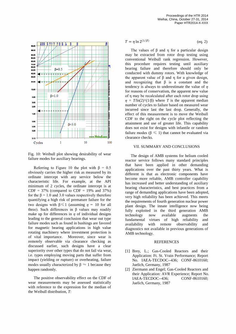
Fig. 10: Weibull plot showing desirability of wear
failure modes for auxiliary bearings.
Referring to Figure 10 the plot with β = 0.5
obviously carries the higher risk as measured by its
ordinate intercept with any service below the
characteristic life. For example, at the API
minimum of 2 cycles, the ordinate intercept is at
CDF = 37% (compared to CDF = 19% and 37%)
for the β = 1.0 and 3.0 values respectively therefore
quantifying a high risk of premature failure for the
two designs with β≤1 (assuming η = 10 for all
three). Such differences in β values may readily
make up for differences in η of individual designs
leading to the general conclusion that wear out type
failure modes such as found in bushings are favored
for magnetic bearing applications in high value
rotating machinery where investment protection is
of vital importance. Moreover, since wear is
remotely observable via clearance checking as
discussed earlier, such designs have a clear
superiority over other types that do not fail via wear,
i.e. types employing moving parts that suffer from
impact (yielding or rupture) or overheating, failure
modes usually characterized by β ≈ 1 because they
happen randomly.
The positive observability effect on the CDF of
wear measurements may be assessed statistically
with reference to the expression for the median of
the Weibull distribution, T:
𝑇 = 𝜂 ln 2(1 𝛽)⁄ (eq. 2)
The values of β and η for a particular design
may be extracted from rotor drop testing using
conventional Weibull rank regression. However,
this procedure requires testing until auxiliary
bearing failure and therefore should only be
conducted with dummy rotors. With knowledge of
the apparent value of β and η for a given design,
and recognizing that β is a constant and the
tendency is always to underestimate the value of η
for reasons of conservatism, the apparent new value
of η may be recalculated after each rotor drop using
η = T/ln(2)^(1/β) where T is the apparent median
number of cycles to failure based on measured wear
incurred since last the last drop. Generally, the
effect of this measurement is to move the Weibull
CDF to the right on the cycle plot reflecting the
attainment and use of greater life. This capability
does not exist for designs with infantile or random
failure modes (β ≤ 1) that cannot be evaluated via
clearance checks.
VII. SUMMARY AND CONCLUSIONS
The design of AMB systems for helium cooled
reactor service follows many standard principles
that have been applied in other demanding
applications over the past thirty years. What is
different is that as electronic components have
become more reliable, AMB controller capability
has increased and better understanding of auxiliary
bearing characteristics, and best practices from a
range of demanding applications have been adopted,
very high reliability has been achieved. This meets
the requirements of fourth generation nuclear power
plant design. The innate intelligence now being
fully exploited in the third generation AMB
technology now available augments the
fundamental virtues of high reliability and
availability with remote observability and
diagnostics not available in previous generations of
AMB technology.
REFERENCES
[1] Brey, L.; Gas-Cooled Reactors and their
Application: Ft. St. Vrain Performance; Report
No. IAEA-TECDOC--436; CONF-8610160;
Juelich, Germany, 1987
[2] Ziermann and Engel; Gas-Cooled Reactors and
their Application: AVR Experience; Report No.
IAEA-TECDOC--436; CONF-8610160;
Juelich, Germany, 1987

Proceedings of the HTR 2014 Weihai, China, October 27-31, 2014
Paper HTR2014-X-XXX
[3] Glahe and Stolzl, Circulator Performance
during THTR Trial and Post-Commissioning
Operation, Report No. IWGGCR--17; CONF-
8711106, San Diego, 1988
[4] Newmark. N. M., John A. Blume, and Kanwar
K. Kapur, "Design Response Spectra for
Nuclear Power Plants," ASCE Structural
Engineering Meeting, San Francisco. April
1973.
[5] N. M. Newmark Consulting Engineering
Services, "A Study of Vertical SW- Horizontal
Earthquake Spectra," Urbana, Illinois, USAEC
Contract No. AT(49-$)-2667, WASH-1 255,
April 1973.
[6] John A. Blume & Associates,
"Recommendations for Shape of Earthquake
Response spectra," San Francisco, California,
USAEC Contract No. AT(49-$)-301 I. WASH-
1254. February 1973.
[7] US NRC Regulatory Guide 1.60, 1973
[8] ASME QME-1-2000, Qualification of Active
Mechanical Equipment Used in Nuclear Power
Plants, 2000
[9] IEEE Std 344-2004, Recommended Practice
for Seismic Qualification of Class 1E
Equipment for Nuclear Power Generating
Stations, 2004
[10] Vestroni, F. and Lucarelli, V.; Design
Requirements for Seismic Safety of NPP;
Tivoli, Italy, 2010
[11]American Petroleum Institute Standard API
617, 8th Edition, 2014
[12]International Standards Organization Standards,
ISO 14839-1,-2,-3,-4
[13]Abernathy, R. B., The New Weibull Handbook,
4th Edition, 2000