The Design and Analysis of Low Solidity Vaned … · for Increased Turbopump Throttling Capability...
13
American Institute of Aeronautics and Astronautics 1 The Design and Analysis of Low Solidity Vaned Diffusers for Increased Turbopump Throttling Capability Scott Sargent 1 Barber Nichols Inc., Arvada, CO, 80002 Low solidity vaned diffusers (LSVD) offer the potential to increase static pressure recovery over that attainable with a vaneless diffuser and do so over a flow range larger than what is possible with a conventional vaned diffuser (CVD). Such a technology could benefit liquid rocket engine (LRE) turbopumps required to perform deep throttle operations such as those envisioned for ascent/descent operations. In this test effort 5 LSVD concepts are designed, manufactured, and tested in a water test loop at Barber-Nichols Inc. along with a CVD configuration to provide baseline comparison data. The LSVDs were successful in offering a consistent static pressure recovery over a flow coefficient range analogous to deep throttle operation in a turbopump and achieved a level of increased pump head coefficient higher than the CVD diffuser at flow coefficients below 0.09. Shaping the leading edge of the second LSVD concept based on predictions from a modified potential flow free-streamline analysis produces higher pump head coefficients over the LSVD concept with a full radius leading edge. The test results suggest that the LSVD design guidelines for low speed compressors may be successfully applied to pumps, and further that the adaptation and modification of an existing free-streamline analysis methodology to guide the contouring of diffuser vane leading edges was successful. Nomenclature CVD = conventional vaned diffuser c m = impeller discharge meridonal flow velocity ΔH = head (ft) LRE = liquid rocket engine LSVD = low solidity vaned diffuser N = shaft speed (rpm) NPSH = net positive suction head (ft) N s = specific speed, √ ∆ 0.75 Q = volumetric flow rate (gpm) r 3 = diffuser inlet radius r 4 = diffuser discharge radius t = vane thickness U = impeller tip speed (ft/sec) Z = vane number λ = ℎ ϕ = impeller discharge flow coefficient, ψ = pump head coefficient, ∆ 2 ⁄ σ = vane solidity I. Introduction EEP throttle capability in pump-fed liquid rocket engines (LREs) places unique challenges on centrifugal turbopumps. Engine systems required to perform deep throttle operations such as those envisioned for ascent/descent missions require turbomachinery capable of operation at Q/N ratios of 0.2 to 1.1 for 10:1 engine throttle operation 1 . Such operational ranges are particularly difficult for vaned radial diffusers which are prone to fluid separation and stall at extreme Q/N operation. Vaneless diffusers while capable of wide flow range operation, lack the static pressure recovery capability possessed by vaned diffusers. Low solidity vaned diffusers (LSVDs) 1 Project Engineer, Barber Nichols Inc., 6325 W 55 th Ave., Arvada, CO 80002, senior member AIAA. D
Transcript of The Design and Analysis of Low Solidity Vaned … · for Increased Turbopump Throttling Capability...
American Institute of Aeronautics and Astronautics
1
The Design and Analysis of Low Solidity Vaned Diffusers
for Increased Turbopump Throttling Capability
Scott Sargent1
Barber Nichols Inc., Arvada, CO, 80002
Low solidity vaned diffusers (LSVD) offer the potential to increase static pressure recovery over that
attainable with a vaneless diffuser and do so over a flow range larger than what is possible with a
conventional vaned diffuser (CVD). Such a technology could benefit liquid rocket engine (LRE) turbopumps
required to perform deep throttle operations such as those envisioned for ascent/descent operations. In this
test effort 5 LSVD concepts are designed, manufactured, and tested in a water test loop at Barber-Nichols
Inc. along with a CVD configuration to provide baseline comparison data. The LSVDs were successful in
offering a consistent static pressure recovery over a flow coefficient range analogous to deep throttle
operation in a turbopump and achieved a level of increased pump head coefficient higher than the CVD
diffuser at flow coefficients below 0.09. Shaping the leading edge of the second LSVD concept based on
predictions from a modified potential flow free-streamline analysis produces higher pump head coefficients
over the LSVD concept with a full radius leading edge. The test results suggest that the LSVD design
guidelines for low speed compressors may be successfully applied to pumps, and further that the adaptation
and modification of an existing free-streamline analysis methodology to guide the contouring of diffuser vane
leading edges was successful.
Nomenclature
CVD = conventional vaned diffuser
cm = impeller discharge meridonal flow velocity
ΔH = head (ft)
LRE = liquid rocket engine
LSVD = low solidity vaned diffuser
N = shaft speed (rpm)
NPSH = net positive suction head (ft)
Ns = specific speed, 𝑁√𝑄
∆𝐻0.75
Q = volumetric flow rate (gpm)
r3 = diffuser inlet radius
r4 = diffuser discharge radius
t = vane thickness
U = impeller tip speed (ft/sec)
Z = vane number
λ = 𝐷𝑖𝑛𝑙𝑒𝑡 ℎ𝑢𝑏
𝐷𝑖𝑛𝑙𝑒𝑡 𝑡𝑖𝑝
ϕ = impeller discharge flow coefficient, 𝑐𝑚
𝑈
ψ = pump head coefficient, ∆𝐻
𝑈2 𝑔⁄
σ = vane solidity
I. Introduction
EEP throttle capability in pump-fed liquid rocket engines (LREs) places unique challenges on centrifugal
turbopumps. Engine systems required to perform deep throttle operations such as those envisioned for
ascent/descent missions require turbomachinery capable of operation at Q/N ratios of 0.2 to 1.1 for 10:1 engine
throttle operation1. Such operational ranges are particularly difficult for vaned radial diffusers which are prone to
fluid separation and stall at extreme Q/N operation. Vaneless diffusers while capable of wide flow range operation,
lack the static pressure recovery capability possessed by vaned diffusers. Low solidity vaned diffusers (LSVDs)
1 Project Engineer, Barber Nichols Inc., 6325 W 55
th Ave., Arvada, CO 80002, senior member AIAA.
D
American Institute of Aeronautics and Astronautics
2
offer the potential for static pressure recovery over a wider Q/N range than is possible with a conventional vaned
diffuser (CVD) while attaining a static pressure recovery greater than possible with a vaneless diffuser. An increase
in pump stage static pressure assists in increasing pump efficiency which in turn can reduce the amount of propellant
required for a given mission allowing for an increased payload or reduction in vehicle mass.
The concept of a LSVD for centrifugal pump applications is credited to Sutton2 with further development for
centrifugal compressors performed by Senoo3. The design premise is that by eliminating the aerodynamic throat
through the diffuser the stage flow range is controlled by the impeller allowing the stage to operate out to its choked
flow limit provided, as mentioned by Holweg4, “the diffuser vane incidence is matched properly”.
The bulk of the published literature concerning LSVDs comes unsurprisingly from the compressor industry
where the use of vaned diffusers is more common than for pumps. Although LSVDs have been applied to pumps no
known work regarding the efficacy of using compressor-derived design guidelines is known to be available. This
work seeks to explore the potential benefits of LSVDs as applied to pumps and add to the knowledge base of
LSVDs by examining the effects of diffuser leading edge geometry and incidence angle.
II. LSVD Design Procedure
The majority of the published literature relating to the design and analysis of LSVDs concerns application in
compressors flowing compressible fluids and are not specific to pumps using incompressible fluids. Wherever
possible, data relating to low Mach number operation (< 0.4) has been used for creation of the LSVD pump design
strategy.
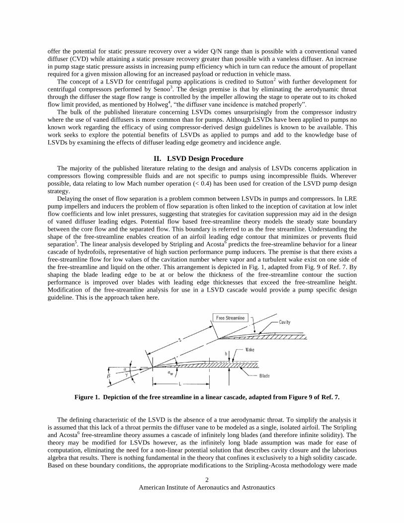
Delaying the onset of flow separation is a problem common between LSVDs in pumps and compressors. In LRE
pump impellers and inducers the problem of flow separation is often linked to the inception of cavitation at low inlet
flow coefficients and low inlet pressures, suggesting that strategies for cavitation suppression may aid in the design
of vaned diffuser leading edges. Potential flow based free-streamline theory models the steady state boundary
between the core flow and the separated flow. This boundary is referred to as the free streamline. Understanding the
shape of the free-streamline enables creation of an airfoil leading edge contour that minimizes or prevents fluid
separation5. The linear analysis developed by Stripling and Acosta
6 predicts the free-streamline behavior for a linear
cascade of hydrofoils, representative of high suction performance pump inducers. The premise is that there exists a
free-streamline flow for low values of the cavitation number where vapor and a turbulent wake exist on one side of
the free-streamline and liquid on the other. This arrangement is depicted in Fig. 1, adapted from Fig. 9 of Ref. 7. By
shaping the blade leading edge to be at or below the thickness of the free-streamline contour the suction
performance is improved over blades with leading edge thicknesses that exceed the free-streamline height.
Modification of the free-streamline analysis for use in a LSVD cascade would provide a pump specific design
guideline. This is the approach taken here.
Figure 1. Depiction of the free streamline in a linear cascade, adapted from Figure 9 of Ref. 7.
The defining characteristic of the LSVD is the absence of a true aerodynamic throat. To simplify the analysis it
is assumed that this lack of a throat permits the diffuser vane to be modeled as a single, isolated airfoil. The Stripling
and Acosta6 free-streamline theory assumes a cascade of infinitely long blades (and therefore infinite solidity). The
theory may be modified for LSVDs however, as the infinitely long blade assumption was made for ease of
computation, eliminating the need for a non-linear potential solution that describes cavity closure and the laborious
algebra that results. There is nothing fundamental in the theory that confines it exclusively to a high solidity cascade.
Based on these boundary conditions, the appropriate modifications to the Stripling-Acosta methodology were made

American Institute of Aeronautics and Astronautics
3
and the theory implemented for use in designing LSVDs, with the goal of designing a separation-resistant diffuser
vane leading edge.
A. Test Articles
LSVDs comprised of flat camber lines are used in this test effort. This geometry was selected based on its
simplicity of design, ease of implementation, and effectiveness. Engeda8,9
successfully demonstrated such a design
in his work. The technical approach for the design of the LSVDs described here relies heavily on data and
information contained within these papers and retains the nomenclature of his work. The nomenclature and
geometry description is shown in Fig. 2.
Figure 2. Nomenclature and geometry description for LSVDs from Engeda
8.
The first step in the design of the LSVDs is the selection of the design incidence angle, id. Two LSVD design
incidence angles were selected for testing, a positive incidence of 3 degrees and a negative angle of -0.5 degrees.
Sorokes and Welch10
provide data suggesting that higher compressor efficiencies were obtained with slightly
negative incidence angles. Hohlweg's4 data showed a maximum efficiency with an incidence angle of id = -1.9. A
negative incidence angle allows for a bias toward improved low flow performance as it limits the largest positive
incidence that will occur at the lowest flow coefficient.
Two distinct designs are used for the leading edge shape of the LSVD test articles. The first design is a full
radius leading edge, designated the “full round” configuration while the second design uses the modified free-
streamline theory to shape the leading edges. The free-streamline leading edges are referred to as the “shaped”
configuration.
For a given LSVD incidence angle design 2 leading edge configurations are created for a total of 4 LSVD
designs. A separate and distinct geometry was created based on a modified NACA 65 series airfoil with no camber
as a comparison to the flat plate LSVD designs. The NACA 65 series geometry was selected as it has been
successfully used in the past for diffuser designs. Additionally a CVD was designed and used as a control case
against which to judge the performance of the LSVD configurations.

American Institute of Aeronautics and Astronautics
4
The diffuser radius ratio, the ratio between the diffuser vane leading edge radius and the impeller blade trailing
edge radius (r3/r2) is taken from the guidelines given in Ref. 10. The LSVDs are found to be more effective when
positioned at a lower radius ratio value. For this test article 2 radius ratios of 1.08 and 1.13 are used.
The remaining design parameters are chosen based on consideration of non-hydrodynamic constraints. The
number of vanes Z, is chosen as a multiple of 3 to make use of the diffuser anti-rotation and orientation features
present in the test article pump. For this investigation 9 vanes are used for the LSVDs. The blade thickness tbl is
chosen to provide adequate strength and material to allow for the insertion of anti-rotation pins.
The suction side leading edge shape for the shaped LSVD is designed for a flow rate less than the design flow
rate of 180 gpm. The strategy is to accommodate the flow conditions at a much lower than design flow in an effort
to increase the diffuser performance at the lower flow coefficients where high incidence angles are encountered.
With the incidence angle, radius ratio, vane number, and blade thickness chosen, the inlet blade angle β3 can be
found based on the impeller discharge flow characteristics at the design point. The diffuser discharge blade angle, β4
and radius r4 are then determined through the following relations given in Ref. 8.
(1)
(2)
For the current test article a solidity of ~ 0.8 was used as it provided a good compromise between the required
structural integrity and desire to use as low of a solidity as possible. Test results of Refs. 8 and 10 indicate that better
stability at low flows is obtained with low solidities. Solidity is given in Ref. 8 and is defined as
(3)
A summary of the diffuser test articles and their corresponding design parameters is given in Table 1.
Table 1. LSVD design parameter summary.
The 5 LSVD cascades created for the test program are shown in Fig. 3 through Fig. 8.
β4=tan−1
(tanβ3+
2−sin(180
Z)
cosβ3
−tbl
2r3sinβ3
)
r4=r 3
cosβ3
cosβ4
σ2=(l / s)
2=
(r 4/ r3)2+1−2(r4 /r3)cos(β4−β3)
2−cos(360/ z )
b3/b2 r3/r2 r3 (in) β3 (deg) β4 (deg) Z σ tbl (in) id (deg) Qd (gpm) Nd (rpm)
LSVD Full Round 12 deg 1.43 1.08 2.8 12 33.3 9 0.79 0.125 3.0 180 3471
LSVD Shaped 12 deg 1.43 1.08 2.8 12 32.3 9 0.76 0.125 3.0 180 3471
LSVD Full Round 9 deg 1.43 1.13 2.93 8.5 28.1 9 0.77 0.125 -0.5 180 3471
LSVD Shaped 9 deg 1.43 1.13 2.92 8.5 28.1 9 0.77 0.125 -0.5 180 3471
LSVD NACA 65 series 1.43 1.13 2.93 8.5 32.3 9 0.79 0.054 -0.5 180 3471
CVD 1.43 1.13 2.93 14 24.4 12 NA - 5.0 180 3471

American Institute of Aeronautics and Astronautics
5
Figure 3. LSVD with a full radius leading edge and 12 degree inlet angle.
Figure 4. LSVD with a shaped leading edge suction side and 12 degree inlet angle.
Figure 5. LSVD with a full radius leading edge and 9 degree inlet angle.

American Institute of Aeronautics and Astronautics
6
Figure 6. LSVD with a shaped leading edge suction side and 9 degree inlet angle.
Figure 7. LSVD based on a modified NACA 65 series airfoil with 9 degree inlet angle.
Figure 8. Conventional vaned diffuser with a 14 degree inlet angle.

American Institute of Aeronautics and Astronautics
7
The diffuser assemblies are created through the use of additive manufacturing (AM), allowing rapid
manufacturing turnaround times and for a lower cost test article as opposed to machined aluminum.
III. Test Facility
The test loop for this investigation is shown schematically in Fig. 9. The test loop is constructed in the test area
at Barber-Nichols Inc. (BNI) and consists of a 3000 gallon water tank connected to the test pump article via 4 inch
schedule 80 PVC pipe. The water tank together with its discharge and return piping are shown in Fig. 10. The water
tank is located outdoors while the rest of the loop is indoors, inside the test area. Two couplings, isolation valves and
hose bibs allow the loop to be partially disassembled and drained after each diffuser configuration is tested. A sump
pump controlled by a thermostat switch is placed inside the tank to re-circulate the water and prevent freezing of the
lines when the temperature outside drops below freezing.
Figure 9. Water test loop schematic.
Figure 10. 3000 gallon water tank with discharge and return piping.

American Institute of Aeronautics and Astronautics
8
Mass flow measurement in the loop is via an ASME standard orifice run. Flow rate through the test loop is
controlled by a 4 inch gate valve. The orifice run and flow control gate valve are shown in Fig. 11.
Figure 11. Test facility orifice run with throttle valve.
Pressure is measured in 8 locations throughout the facility. Temperature is measured via thermocouples in 4
locations in the test loop, while pressure and temperature data is recorded by means of a digital data acquisition
(DAQ) system. Speed is measured by use of a strobe light using the motor cooling fan as a target.
To focus available resources on LSVD test article design and testing, the decision was made to identify and
procure an existing off the shelf pump to provide the inlet conditions to the test diffusers. The test pump selection
criteria consisted of finding a pump with a pre-existing vaned diffuser that could be easily modified and has a
specific speed representative of that used in a rocket engine turbopump. The Pentair WhisperFloXFK-20 pool pump
was selected for this task. A picture of the pump is shown in Fig. 12.
Figure 12. Pentair WhisperFloXFK-20 test pump.

American Institute of Aeronautics and Astronautics
9
The pump runs at a nominal specific speed, Ns of 1600 which is comparable to the Ns of several LRE oxidizer
turbopumps. The pump uses a fixed speed 5HP 2 pole motor to provide power to the impeller and is equipped with a
CVD assembly that is easily modified for purposes of the test effort.
IV. Test Results
Test data is taken at a range of flow coefficients corresponding to the Q/N range representative of 10:1 engine
system throttling. Data is acquired in a double-pass procedure to control for any transient effects that could be
present in the pump system.
Summary comparisons of the pump discharge head and flow characteristics for all diffuser configurations are
presented in Fig. 13. For the lower range of flow coefficients (0.02 to 0.09) the LSVD with β3 = 9, shaped leading
edge configuration exhibits the highest performance. For the higher flow coefficient range (0.09 to 0.13) the CVD
performs best. It is interesting to note that the β3 = 9, shaped leading edge LSVD is only about 2% lower in head
coefficient even at the highest flow coefficients recorded.
Figure 13. Flow and head coefficient comparison for all diffuser configurations.
Efficiency data, shown in Fig. 14 taken with the CVD and the β3 = 9 diffusers display a consistent behavior with
that seen in Fig. 14. The β3 = 9, shaped leading edge LSVD is the best performer at low flow coefficients and the
CVD the most efficient at the higher flow coefficients. Here again the performance differential between the CVD
and the β3 = 9, shaped leading edge LSVD is quite small.

American Institute of Aeronautics and Astronautics
10
Figure 14. Efficiency comparison for the 9 degree LSVDs compared to the CVD.
A. Blade Angle Comparison
The data from the 2 full round leading edge LSVD configurations is plotted in Fig. 15. The β3 = 9 displays better
performance over the entire range of tested flow coefficients. This result is not surprising for the low flow
coefficients where the incidence on the diffuser vanes is more positive. For the flow coefficient of 0.2 the incidence
angle for the β3 = 9 diffuser is 7.4 degrees while for the β3 = 12 diffuser the incidence is 10.9 degrees. At the highest
flow coefficient value of 0.135 the incidence angle for the β3 = 9 diffuser is -2.1 degrees while for the β3 = 12
diffuser the incidence is 1.34. At this higher flow coefficient it was expected that the β3 = 12 with the lower absolute
incidence angle would have displayed slightly better performance. It is possible that since the data is based on the
pump discharge pressure, and that the difference in head coefficients between the 2 configurations is about 2% or
less that the pump discharge collector is affecting the results.

American Institute of Aeronautics and Astronautics
11
Figure 15. Effect of blade angle on pump performance for the LSVDs with the full round leading edge.
The data from the 2 shaped leading edge LSVD configurations is plotted in Fig. 16, with the data following the
same overall trend as observed in Fig. 15 for the full round configuration diffusers. The incidence angle range is
identical to that seen in Fig. 15. The data from Figs. 15 and 16 show that regardless of leading edge configuration,
the β3 = 9 diffusers perform better over the flow coefficients of interest.
Figure 16. Effect of blade angle on pump performance for the LSVDs with the shaped leading edge.

American Institute of Aeronautics and Astronautics
12
B. Geometry Comparison
Comparison of the effect of geometry for the β3 = 9 LSVDs is shown in Fig. 17. For the low flow coefficient
range of 0.02 – 0.09, the shaped leading edge exhibits the best performance while all the LSVDs produce equivalent
performance over the flow coefficient range of 0.1 to 0.135. No discernable benefit is seen between the full round
configuration and the NACA 65 series airfoil configuration, indicating that in this case the performance of a flat
plate LSVD is equivalent to that of an airfoil shaped vane.
Figure 17. Effect of geometry for β3 = 9 LSVDs.
V. Summary and Conclusions
The use of LSVDs in pump applications has been examined as an enabler for potentially increasing the pressure
recovery of LRE turbopumps over a flow coefficient range anticipated for engine systems capable of a 10:1 throttle
range. General design guidelines developed for centrifugal compressor LSVDs were identified and used together
with a modified free-streamline analysis based on the work in Ref. 6 to design 4 LSVD test articles specifically for
implementation in pumps. The LSVDs were designed at 2 different inlet angles and 2 different leading edge
configurations to examine separately the effects of blade angle and geometry. The LSVD diffusers were all designed
to attempt to improve head coefficient at the lower range of flow coefficients. A CVD and an additional LSVD
based on geometry from a modified NACA 65 series airfoil were created and tested to provide additional
comparison.
For both angle settings the shaped leading edge LSVD configuration provided the best overall pump
performance based on pump head coefficient. These leading edge shapes were determined through use of the
modified free-streamline theory. The airfoil shaped LSVD performed on a par with the flat plate full round leading
edge configuration and displayed no performance advantage. The shaped leading edge configuration for the β3 = 9
LSVD showed the best overall head coefficient performance across all diffusers tested for the low flow coefficient
range while the CVD gave the best performance at the higher flow coefficients. The test data appears to indicate that
the use of the modified free-streamline theory together with flat plate geometry is effective in designing an LSVD
capable of increased head coefficient at low flow coefficient values as compared to a conventional vaned diffuser.
American Institute of Aeronautics and Astronautics
13
Acknowledgments
The author would like to thank Derek O’Neal of the NASA Marshall Space Flight Center for his assistance with
this project. Funding for this project was provided under NASA’s SBIR program.
References 1Hayden, W.R., “Advanced Engine Study, Task D.6 Final Report”, NASA CR-187216, 1992. 2Sutton, E., “The Performance and Flow Conditions Within a Radial Diffuser Fitted with Short Vanes”, British Hydromech.
Res. Assn., Report 946, 1968. 3Senoo, Y., “Low Solidity Circular Cascade for Wide Flow Range Blower”, Proceedings of Advanced Concepts in
Turbomachinery, Fluid Dynamics Institute, Hannover NH, 1981. 4Hohlweg, W.C., Direnzi, G.L., and Aungier, R.H., “Comparison of Conventional and Low Solidity Vaned Diffusers”,
ASME 93-GT-98, 1993. 5Betz, A., Introduction to the Theory of Flow Machines, Oxford, England: Pergamon Press, 1966. 6Stripling, L.B., Acosta A.J., “Cavitation in Turbopumps – Part1”, ASME Journal of Basic Engineering, 1962, pp. 326-338. 7Jakobsen J.K., Liquid Rocket Engine Turbopump Inducers, SP-8052, NASA 1971. 8Engeda, A., “Design and Investigation of Four Low Solidity Vaned Diffusers to Assess the Effect of Solidity and Vane
Number”, ASME 98-GT-252, 1998. 9Engeda, A., “The Design and Performance Results of Simple Flat Plate Low Solidity Vaned Diffusers”, Proc Instn Mech
Engrs Vol 215 Part A: Journal of Power and Energy, 215:109, 2001. 10Sorokes, J.M., Welch, J.P., “Experimental Results on a Rotatable Low Solidity Vaned Diffuser”, ASME 92-GT-19, 1992.