
Turbopump Design and Analysis Approach for Nuclear Thermal ... · PDF fileTurbopump Design and...
36
Turbopump Design and Analysis Approach for Nuclear Thermal Rockets Shu-cheng S. Chen 1 , Joseph P. Veres 2 , and James E. Fittje 3 1 NASA Glenn Research Center, Cleveland, Ohio 44135 2 Chief, Compressor Branch, NASA Glenn Research Center, Cleveland, Ohio 44135 3 Analex Corporation, 1100 Apollo Drive, Brook Park, Ohio 44142 1 (216) 433-3585, [email protected] Abstract. A rocket propulsion system, whether it is a chemical rocket or a nuclear thermal rocket, is fairly complex in detail but rather simple in principle. Among all the interacting parts, three components stand out: they are pumps and turbines (turbopumps), and the thrust chamber. To obtain an understanding of the overall rocket propulsion system characteristics, one starts from analyzing the interactions among these three components. It is therefore of utmost importance to be able to satisfactorily characterize the turbopump, level by level, at all phases of a vehicle design cycle. Here at NASA Glenn Research Center, as the starting phase of a rocket engine design, specifically a Nuclear Thermal Rocket Engine design, we adopted the approach of using a high level system cycle analysis code (NESS) to obtain an initial analysis of the operational characteristics of a turbopump required in the propulsion system. A set of turbopump design codes (PumpDes and TurbDes) were then executed to obtain sizing and performance characteristics of the turbopump that were consistent with the mission requirements. A set of turbopump analyses codes (PUMPA and TURBA) were applied to obtain the full performance map for each of the turbopump components; a two dimensional layout of the turbopump based on these mean line analyses was also generated. Adequacy of the turbopump conceptual design will later be determined by further analyses and evaluation. In this paper, descriptions and discussions of the aforementioned approach are provided and future outlooks are discussed. Keywords: Turbopump; Nuclear Thermal Rocket Engine; Conceptual Design; System Analysis. https://ntrs.nasa.gov/search.jsp?R=20060051740 2018-05-19T20:11:31+00:00Z
Transcript of Turbopump Design and Analysis Approach for Nuclear Thermal ... · PDF fileTurbopump Design and...
Turbopump Design and Analysis Approach for Nuclear Thermal Rockets
Shu-cheng S. Chen1, Joseph P. Veres2, and James E. Fittje3
1NASA Glenn Research Center, Cleveland, Ohio 44135 2Chief, Compressor Branch, NASA Glenn Research Center, Cleveland, Ohio 44135
3Analex Corporation, 1100 Apollo Drive, Brook Park, Ohio 44142 1(216) 433-3585, [email protected]
Abstract. A rocket propulsion system, whether it is a chemical rocket or a nuclear thermal rocket, is fairly complex in detail but rather simple in principle. Among all the interacting parts, three components stand out: they are pumps and turbines (turbopumps), and the thrust chamber. To obtain an understanding of the overall rocket propulsion system characteristics, one starts from analyzing the interactions among these three components. It is therefore of utmost importance to be able to satisfactorily characterize the turbopump, level by level, at all phases of a vehicle design cycle. Here at NASA Glenn Research Center, as the starting phase of a rocket engine design, specifically a Nuclear Thermal Rocket Engine design, we adopted the approach of using a high level system cycle analysis code (NESS) to obtain an initial analysis of the operational characteristics of a turbopump required in the propulsion system. A set of turbopump design codes (PumpDes and TurbDes) were then executed to obtain sizing and performance characteristics of the turbopump that were consistent with the mission requirements. A set of turbopump analyses codes (PUMPA and TURBA) were applied to obtain the full performance map for each of the turbopump components; a two dimensional layout of the turbopump based on these mean line analyses was also generated. Adequacy of the turbopump conceptual design will later be determined by further analyses and evaluation. In this paper, descriptions and discussions of the aforementioned approach are provided and future outlooks are discussed.
Keywords: Turbopump; Nuclear Thermal Rocket Engine; Conceptual Design; System Analysis.
https://ntrs.nasa.gov/search.jsp?R=20060051740 2018-05-19T20:11:31+00:00Z
at L
ewis
Fie
ldG
lenn
Res
earc
h C
ente
r
1
Turb
opum
p D
esig
n an
d A
naly
sis
App
roac
hfo
r Nuc
lear
The
rmal
Roc
kets
Shu
-che
ng S
. Che
n1, J
osep
h P
. Ver
es2 ,
and
Jam
es E
. Fitt
je3
1 NA
SA
Gle
nn R
esea
rch
Cen
ter,
Cle
vela
nd, O
hio
4413
52 C
hief
, Com
pres
sor B
ranc
h, N
AS
A G
lenn
Res
earc
h C
ente
r, C
leve
land
, Ohi
o 44
135
3 Ana
lex
Cor
pora
tion,
110
0 A
pollo
Driv
e, B
rook
Par
k, O
hio
4414
2
Pres
ente
d at
STA
IF-2
006
Con
fere
nce
Alb
uque
rque
, NM
, Feb
ruar
y 15
, 200
6B
yJa
mes
E. F
ittje

at L
ewis
Fie
ldG
lenn
Res
earc
h C
ente
r
2
Turb
opum
p D
esig
n M
etho
dolo
gy D
ata
Flow
NES
S
Pum
pDes
Turb
Des
Turb
A
Pum
pA

at L
ewis
Fie
ldG
lenn
Res
earc
h C
ente
r
3
NES
S (N
ucle
ar E
ngin
e Sy
stem
Sim
ulat
ion)
Cod
e Fe
atur
es a
nd C
apab
ilitie
s•D
evel
oped
by
NA
SA
/LeR
C, S
AIC
, and
Wes
tingh
ouse
in e
arly
199
0’s
to
supp
ort o
ngoi
ng a
nd fu
ture
stu
dies
of N
ER
VA
-bas
ed N
TR e
ngin
e sy
stem
an
d st
age
desi
gn e
fforts
•NE
SS
is b
ased
on
the
Exp
ande
d Li
quid
Eng
ine
Sim
ulat
ion
(ELE
S)
prog
ram
mod
ified
to in
clud
e so
lid-c
ore
reac
tor d
esig
n m
odel
s•W
estin
ghou
se (r
espo
nsib
le fo
r the
reac
tor s
ubsy
stem
dur
ing
the
NE
RV
A
prog
ram
) pro
vide
d re
acto
r des
ign
mod
els
for a
nea
r-te
rm N
ER
VA
-der
ived
sy
stem
(EN
AB
LER
I) a
nd a
n up
grad
ed v
ersi
on o
f thi
s en
gine
(EN
AB
LER
II)
•NE
SS
can
mod
el e
xpan
der,
gas
gene
rato
r and
ble
ed c
ycle
s, a
long
with
m
ulti-
redu
ndan
t pro
pella
nt p
ump
feed
sys
tem
s•T
urbo
mac
hine
ry d
esig
n op
tions
incl
ude
mul
tista
ge a
xial
and
trad
ition
al
cent
rifug
al p
umps
•NE
SS
is u
sed
for r
apid
, pre
limin
ary
deta
iled
desi
gn a
naly
sis
ofbo
th th
e re
acto
r and
key
eng
ine
subs
yste
ms.
The
cod
e de
sign
s th
e re
acto
r,tu
rbom
achi
nery
, tan
kage
, noz
zle,
line
s an
d va
lves
in te
rms
of b
oth
wei
ght
and
perfo
rman
ce/o
pera
ting
char
acte
ristic
s

at L
ewis
Fie
ldG
lenn
Res
earc
h C
ente
r
4
NES
S Ex
pand
er C
ycle
Flo
w P
ath
(Ena
bler
1)
at L
ewis
Fie
ldG
lenn
Res
earc
h C
ente
r
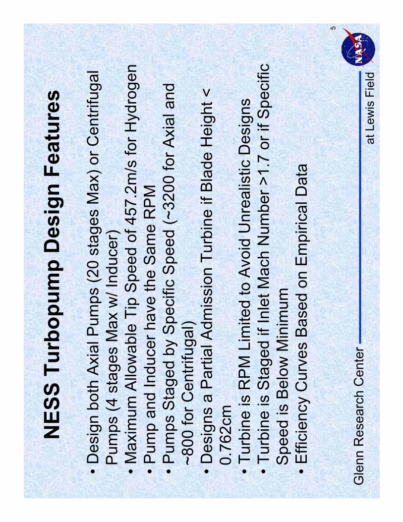
5
NES
S Tu
rbop
ump
Des
ign
Feat
ures
•Des
ign
both
Axi
al P
umps
(20
stag
es M
ax) o
r Cen
trifu
gal
Pum
ps (4
sta
ges
Max
w/ I
nduc
er)
•Max
imum
Allo
wab
le T
ip S
peed
of 4
57.2
m/s
for H
ydro
gen
•Pum
p an
d In
duce
r hav
e th
e S
ame
RP
M•P
umps
Sta
ged
by S
peci
fic S
peed
(~32
00 fo
r Axi
al a
nd~8
00 fo
r Cen
trifu
gal)
•Des
igns
a P
artia
l Adm
issi
on T
urbi
ne if
Bla
de H
eigh
t <
0.76
2cm
•Tur
bine
is R
PM
Lim
ited
to A
void
Unr
ealis
tic D
esig
ns•T
urbi
ne is
Sta
ged
if In
let M
ach
Num
ber >
1.7
or if
Spe
cific
Spe
ed is
Bel
ow M
inim
um•E
ffici
ency
Cur
ves
Bas
ed o
n E
mpi
rical
Dat
a
at L
ewis
Fie
ldG
lenn
Res
earc
h C
ente
r
6
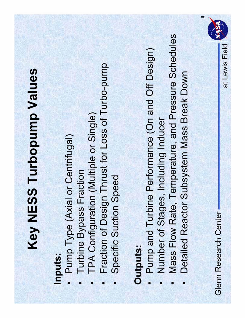
Key
NES
S Tu
rbop
ump
Valu
es
Inpu
ts:
•P
ump
Type
(Axi
al o
r Cen
trifu
gal)
•Tu
rbin
e B
ypas
s Fr
actio
n•
TPA
Con
figur
atio
n (M
ultip
le o
r Sin
gle)
•Fr
actio
n of
Des
ign
Thru
st fo
r Los
s of
Tur
bo-p
ump
•S
peci
fic S
uctio
n S
peed
Out
puts
:•
Pum
p an
d Tu
rbin
e P
erfo
rman
ce (O
n an
d O
ff D
esig
n)•
Num
ber o
f Sta
ges,
Incl
udin
g In
duce
r•
Mas
s Fl
ow R
ate,
Tem
pera
ture
, and
Pre
ssur
e S
ched
ules
•D
etai
led
Rea
ctor
Sub
syst
em M
ass
Bre
ak D
own

at L
ewis
Fie
ldG
lenn
Res
earc
h C
ente
r
7
NES
S Sy
stem
Inpu
ts S
umm
ary
•Exp
ande
r Cyc
le•E
nabl
er-I
(Incr
ease
d C
ompu
tatio
nal D
esig
n S
pace
)•2
700K
Cha
mbe
r Tem
pera
ture
•689
4.75
kPa
Cha
mbe
r Pre
ssur
e•3
00:1
Noz
zle
Are
a R
atio
•66.
7kN
and
111
.2kN
Thr
ust L
evel
s•S
ingl
e C
entri
fuga
l Pum
p•P
ump
and
Turb
ine
on C
omm
on S
haft
•Cen
trifu
gal P
ump
(Spe
cific
Suc
tion
Spe
ed o
f 20,
000)
•Reg
ener
ativ
e N
ozzl
e C
oolin
g to
an
Are
a R
atio
of 2
5:1

at L
ewis
Fie
ldG
lenn
Res
earc
h C
ente
r
8
NES
S Pu
mp
Des
ign
Out
puts 67
8.93
392.
87W
eigh
t (N
)25
.35
19.5
3D
iam
eter
(cm
)68
.20%
68.3
0%Ef
ficie
ncy
3057
.618
09.1
Shaf
t Wor
k (k
W)
12.5
67.
53M
ass
Flow
Rat
e (k
g/s)
534.
4734
.47
NPS
P (k
Pa)
33
Num
ber o
f Sta
ges
2000
020
000
Suct
ion
Spec
ific
Spee
d23
967
3093
7R
PM11
.64
11.4
9Pr
essu
re R
ise
(MPa
)11
1.2
66.7
2Th
rust
Lev
el (k
N)

at L
ewis
Fie
ldG
lenn
Res
earc
h C
ente
r
9
NES
S Tu
rbin
e D
esig
n O
utpu
ts 10.5
646.
273
Mas
s Fl
ow R
ate
(kg/
s)
269.
217
2.2
Wei
ght (
N)
70%
70%
Effic
ienc
y20
.42
15.8
Dia
met
er (c
m)
1.29
41.
274
Pres
sure
Rat
io
Thru
st L
evel
(kN
)
22
Num
ber
of S
tage
s
27.8
27.7
Tem
pera
ture
Dro
p (K
)2.
2063
2.05
67Pr
essu
re D
rop
(MPa
)11
1.2
66.7
2
2396
730
937
RPM
4648
Spec
ific
Spee
d

at L
ewis
Fie
ldG
lenn
Res
earc
h C
ente
r
10
Pum
pDes
Pum
p D
esig
n C
ode
•S
tatio
n-by
-Sta
tion
Mea
n Li
ne C
ode
•Es
timat
es H
ydra
ulic
Los
ses
Alo
ng th
e Fl
ow P
ath
(Ful
ly
Dev
elop
ed In
tern
al F
low
bas
ed o
n E
mpi
rical
and
Sem
i-Em
piric
al
Dat
a)•
Flow
Ass
umed
to b
e in
The
rmod
ynam
ic L
ocal
Qua
si-E
quili
briu
m•
Em
piric
al a
nd S
emi-E
mpi
rical
Flo
w P
ath
Loss
es•
Can
Per
form
Inve
rse
Des
ign
and
Con
stra
ined
Opt
imiz
atio
n•
Axia
l Ind
ucer
and
Cen
trifu
gal M
odel
s ar
e Fu
nctio
nally
Inte
grat
ed•
Rea
l Gas
Pro
perti
es•
Val
idat
ed A
gain
st th
e P
&W
ATD
LH2,
MK
15-O
, and
MK
48-O
P
umps
at L
ewis
Fie
ldG
lenn
Res
earc
h C
ente
r
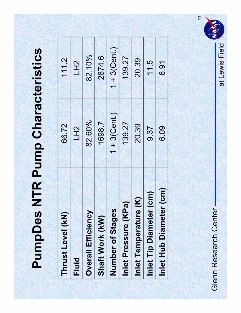
11
Pum
pDes
NTR
Pum
p C
hara
cter
istic
s
11.5
9.37
Inle
t Tip
Dia
met
er (c
m)
20.3
920
.39
Inle
t Tem
pera
ture
(K)
1 +
3(C
ent.)
1 +
3(C
ent.)
Num
ber o
f Sta
ges
2874
.616
98.7
Shaf
t Wor
k (k
W)
82.1
0%82
.60%
Ove
rall
Effic
ienc
y
Thru
st L
evel
(kN
)Fl
uid
6.91
6.09
Inle
t Hub
Dia
met
er (c
m)
139.
2713
9.27
Inle
t Pre
ssur
e (K
Pa)
LH2
LH2
111.
266
.72
at L
ewis
Fie
ldG
lenn
Res
earc
h C
ente
r
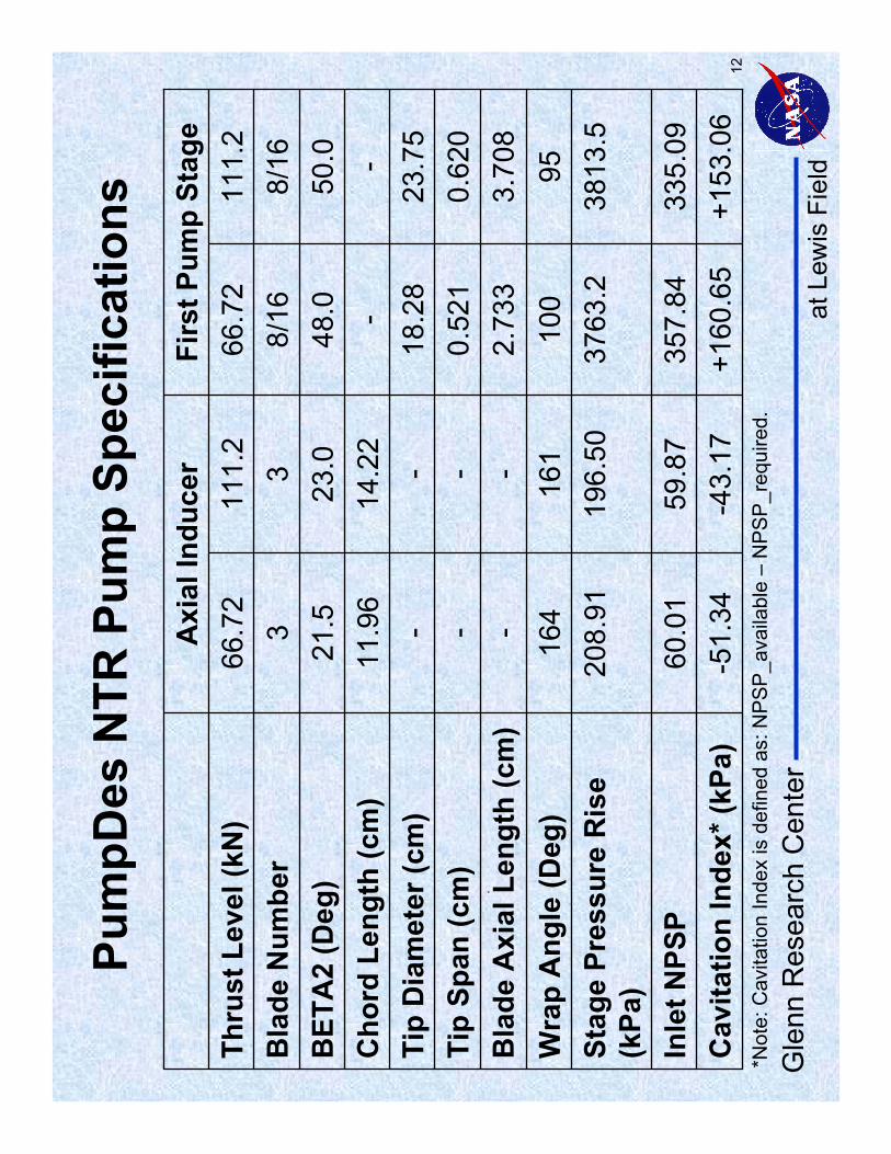
12
.
*Not
e: C
avita
tion
Inde
x is
def
ined
as:
NP
SP
_ava
ilabl
e –
NP
SP
_req
uire
d.
Pum
pDes
NTR
Pum
p Sp
ecifi
catio
ns
--
14.2
211
.96
Cho
rd L
engt
h (c
m)
+153
.06
+160
.65
-43.
17-5
1.34
Cav
itatio
n In
dex*
(kPa
)60
.01
208.
9116
4---
21.53
66.7
2A
xial
Indu
cer
3813
.537
63.2
196.
50St
age
Pres
sure
Ris
e (k
Pa)
335.
0935
7.84
59.8
7In
let N
PSP
111.
266
.72
111.
2Th
rust
Lev
el (k
N)
50.0
48.0
23.0
BET
A2
(Deg
)
0.62
00.
521
-Ti
p Sp
an (c
m)
9510
016
1W
rap
Ang
le (D
eg)
3.70
82.
733
-B
lade
Axi
al L
engt
h (c
m)
23.7
518
.28
-Ti
p D
iam
eter
(cm
)
8/16
8/16
3B
lade
Num
ber
Firs
t Pum
p St
age
at L
ewis
Fie
ldG
lenn
Res
earc
h C
ente
r
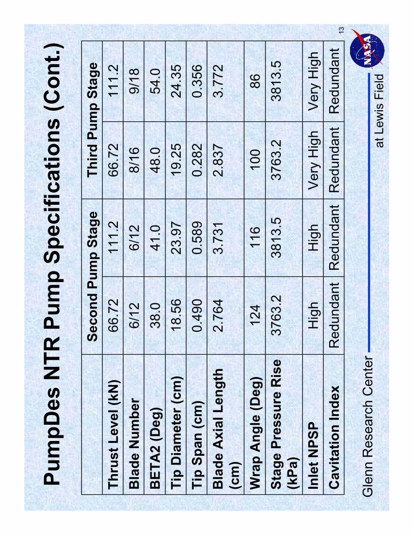
13R
edun
dant
Red
unda
ntR
edun
dant
Red
unda
ntC
avita
tion
Inde
xH
igh
3763
.212
4
2.76
40.
490
18.5
638
.06/
1266
.72
Seco
nd P
ump
Stag
e
3813
.537
63.2
3813
.5St
age
Pres
sure
Ris
e (k
Pa)
Ver
y H
igh
Ver
y H
igh
Hig
hIn
let N
PSP
111.
266
.72
111.
2Th
rust
Lev
el (k
N)
54.0
48.0
41.0
BET
A2
(Deg
)
0.35
60.
282
0.58
9Ti
p Sp
an (c
m)
8610
011
6W
rap
Ang
le (D
eg)
3.77
22.
837
3.73
1B
lade
Axi
al L
engt
h (c
m)
24.3
519
.25
23.9
7Ti
p D
iam
eter
(cm
)
9/18
8/16
6/12
Bla
de N
umbe
r
Third
Pum
p St
age
Pum
pDes
NTR
Pum
p Sp
ecifi
catio
ns (C
ont.)

at L
ewis
Fie
ldG
lenn
Res
earc
h C
ente
r
14
PUM
PA P
ump
Ana
lysi
s C
ode
•U
tiliz
es M
ean
Line
Mod
elin
g M
etho
d to
Mod
el O
ff-D
esig
n P
ump
Per
form
ance
•E
mpi
rical
Cor
rela
tions
use
d to
Mod
el:
•O
ff-D
esig
n E
ffici
ency
•S
lip F
acto
r•
Diff
user
Pre
ssur
e R
ecov
ery
•P
UM
PA
Can
Mod
el:
•A
xial
, Cen
trifu
gal,
and
Mul
tista
ge P
umps
•In
duce
rs (I
nclu
ding
Mix
ed F
low
)•
Rea
l Gas
Pro
perti
es O
btai
ned
from
GA
SP
LUS

at L
ewis
Fie
ldG
lenn
Res
earc
h C
ente
r
15
PUM
PA N
TR P
ump
Perf
orm
ance
Map
(Pre
ssur
e R
ise
vs. V
olum
etric
Flo
w R
ate)

at L
ewis
Fie
ldG
lenn
Res
earc
h C
ente
r
16
PUM
PA N
TR P
ump
Perf
orm
ance
Map
(Con
t.)(P
ower
Req
uire
d vs
. Vol
umet
ric F
low
Rat
e)
at L
ewis
Fie
ldG
lenn
Res
earc
h C
ente
r
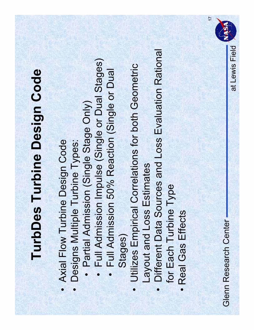
17
Turb
Des
Tur
bine
Des
ign
Cod
e
•A
xial
Flo
w T
urbi
ne D
esig
n C
ode
•D
esig
ns M
ultip
le T
urbi
ne T
ypes
:•
Par
tial A
dmis
sion
(Sin
gle
Sta
ge O
nly)
•Fu
ll A
dmis
sion
Impu
lse
(Sin
gle
or D
ual S
tage
s)•
Full
Adm
issi
on 5
0% R
eact
ion
(Sin
gle
or D
ual
S
tage
s)•
Util
izes
Em
piric
al C
orre
latio
ns fo
r bot
h G
eom
etric
La
yout
and
Los
s E
stim
ates
•D
iffer
ent D
ata
Sou
rces
and
Los
s E
valu
atio
n R
atio
nal
for E
ach
Turb
ine
Type
•Rea
l Gas
Effe
cts
at L
ewis
Fie
ldG
lenn
Res
earc
h C
ente
r
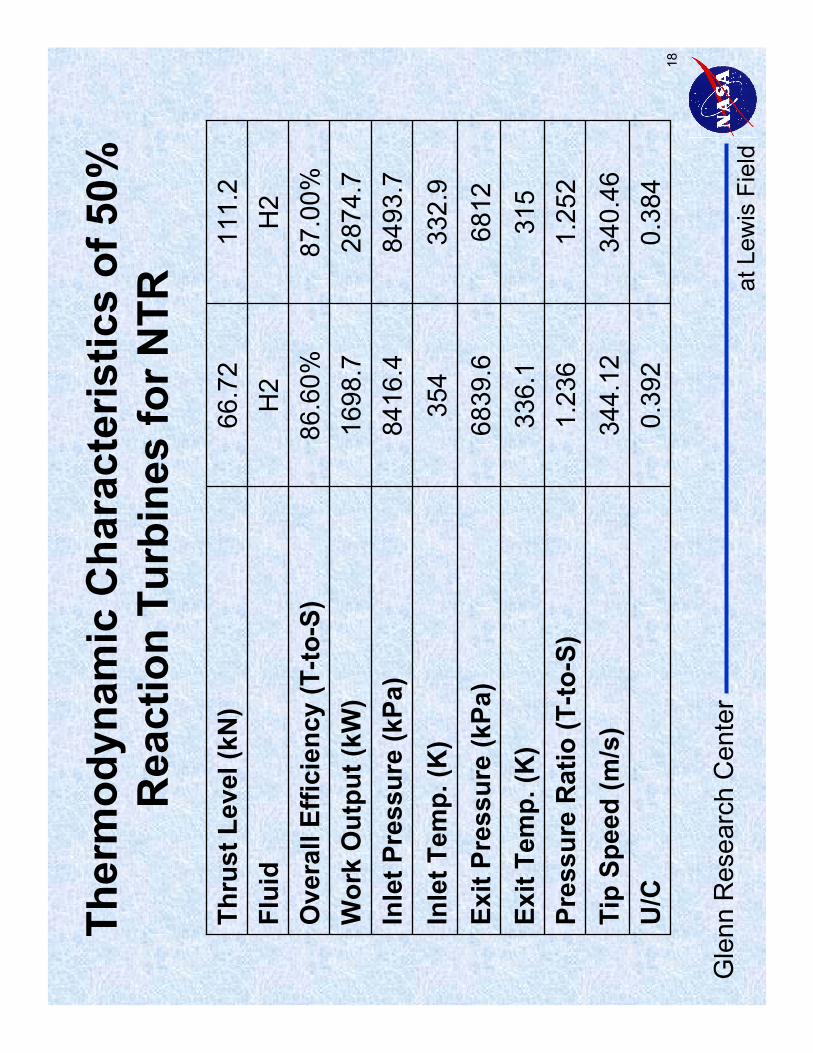
18
Ther
mod
ynam
ic C
hara
cter
istic
s of
50%
R
eact
ion
Turb
ines
for N
TR11
1.2
66.7
2Th
rust
Lev
el (k
N)
Inle
t Tem
p. (K
)In
let P
ress
ure
(kPa
)
Flui
d
0.38
40.
392
U/C
340.
4634
4.12
Tip
Spee
d (m
/s)
1.25
21.
236
Pres
sure
Rat
io (T
-to-S
)31
533
6.1
Exit
Tem
p. (K
)68
1268
39.6
Exit
Pres
sure
(kPa
)33
2.9
354
8493
.784
16.4
2874
.716
98.7
Wor
k O
utpu
t (kW
)87
.00%
86.6
0%O
vera
ll Ef
ficie
ncy
(T-to
-S)
H2
H2
at L
ewis
Fie
ldG
lenn
Res
earc
h C
ente
r
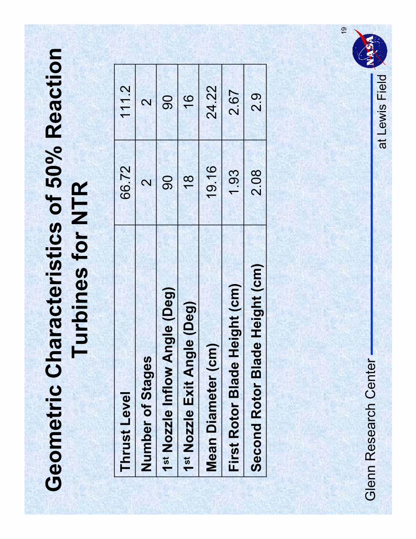
19
Mea
n D
iam
eter
(cm
)1s
tN
ozzl
e Ex
it A
ngle
(Deg
)
Thru
st L
evel
2.9
2.08
Seco
nd R
otor
Bla
de H
eigh
t (cm
)2.
671.
93Fi
rst R
otor
Bla
de H
eigh
t (cm
)24
.22
19.1
6
1618
9090
1stN
ozzl
e In
flow
Ang
le (D
eg)
22
Num
ber o
f Sta
ges
111.
266
.72
Geo
met
ric C
hara
cter
istic
s of
50%
Rea
ctio
n Tu
rbin
es fo
r NTR
at L
ewis
Fie
ldG
lenn
Res
earc
h C
ente
r
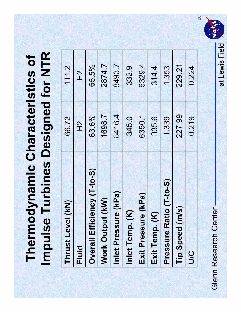
20
Ther
mod
ynam
ic C
hara
cter
istic
s of
Im
puls
e Tu
rbin
es D
esig
ned
for N
TR11
1.2
66.7
2Th
rust
Lev
el (k
N)
Inle
t Tem
p. (K
)In
let P
ress
ure
(kPa
)
Flui
d
0.22
40.
219
U/C
229.
2122
7.99
Tip
Spee
d (m
/s)
1.35
31.
339
Pres
sure
Rat
io (T
-to-S
)31
4.4
335.
6Ex
it Te
mp.
(K)
6329
.463
50.1
Exit
Pres
sure
(kPa
)33
2.9
345.
084
93.7
8416
.428
74.7
1698
.7W
ork
Out
put (
kW)
65.5
%63
.6%
Ove
rall
Effic
ienc
y (T
-to-S
)H
2H
2

at L
ewis
Fie
ldG
lenn
Res
earc
h C
ente
r
21
Geo
met
ric C
hara
cter
istic
s Im
puls
e Tu
rbin
es fo
r NTR
Mea
n D
iam
eter
(cm
)
1stN
ozzl
e Ex
it A
ngle
(Deg
)
Thru
st L
evel
2.00
1.58
Seco
nd R
otor
Bla
de H
eigh
t (cm
)
1.90
1.52
Firs
t Rot
or B
lade
Hei
ght (
cm)
16.2
712
.49
1618
9090
1stN
ozzl
e In
flow
Ang
le (D
eg)
22
Num
ber o
f Sta
ges
111.
266
.72

at L
ewis
Fie
ldG
lenn
Res
earc
h C
ente
r
22
TUR
BA
Tur
bine
Ana
lysi
s C
ode
•U
tiliz
es M
eal L
ine
Flow
Mod
elin
g •
Obt
ains
Des
ign
Poi
nt P
erfo
rman
ce a
nd G
ener
ates
C
hara
cter
istic
Map
s•
Em
piric
ally
Der
ived
Cor
rela
tions
Fro
m E
xist
ing
Eng
ines
an
d Te
st R
igs
•D
esig
n P
oint
Obt
aine
d fro
m C
orre
latio
ns o
f Effi
cien
cy to
S
pout
ing
Vel
ocity
Rat
io•
Off-
Des
ign
Effi
cien
cy O
btai
ned
from
Em
piric
al D
ata
Nor
mal
ized
Rel
ativ
e to
Des
ign
•Fl
ow C
ondi
tions
Cal
cula
ted
at T
ip, H
ub, a
nd M
ean
Line
•
Rea
l Gas
Pro
perti
es fr
om G
AS
PLU
S

at L
ewis
Fie
ldG
lenn
Res
earc
h C
ente
r
23
Two-
Stag
e N
TR T
urbi
ne P
erfo
rman
ce(T
urbi
ne P
ress
ure
Rat
io v
s. F
low
Par
amet
er)
Flow
Par
amet
er
PressureRatio
05
1015
201
1.1
1.2
100%
RP
M
90%
RP
M
80%
RP
M
70%
RP
M
60%
RP
M60
% R
PM70%
RPM80%
RPM
90%
RPM
100%
RPM
Flow
Par
amet
er (m
T1/
2 /P
)
at L
ewis
Fie
ldG
lenn
Res
earc
h C
ente
r
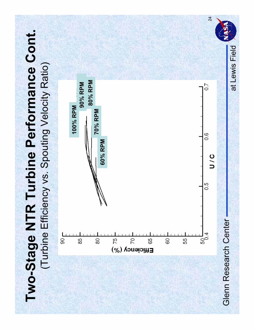
24
Two-
Stag
e N
TR T
urbi
ne P
erfo
rman
ce C
ont.
(Tur
bine
Effi
cien
cy v
s. S
pout
ing
Vel
ocity
Rat
io)
60%
RPM
70%
RPM
80%
RPM
90%
RPM
100%
RPM
at L
ewis
Fie
ldG
lenn
Res
earc
h C
ente
r
25
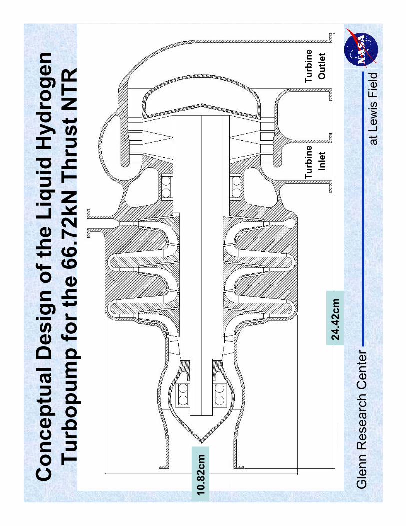
Con
cept
ual D
esig
n of
the
Liqu
id H
ydro
gen
Turb
opum
p fo
r the
66.
72kN
Thr
ust N
TR
24.4
2cm
10.8
2cm
Turb
ine
Inle
tTu
rbin
e O
utle
t
at L
ewis
Fie
ldG
lenn
Res
earc
h C
ente
r
26
Sum
mar
y
•A
Seq
uenc
e fo
r NTR
TP
A D
esig
n an
d A
naly
sis
has
been
Util
ized
and
Pre
sent
ed•
Des
ign
Poi
nt P
erfo
rman
ce a
nd O
ff-D
esig
n P
erfo
rman
ce M
aps
for b
oth
the
Pum
p an
d Tu
rbin
e w
ere
Cal
cula
ted
•In
itial
Con
cept
ual D
esig
n of
TP
A’s
for a
66.
7kN
and
11
1.2k
N T
hrus
t NTR
Eng
ine
have
bee
n C
ompl
eted
•Fo
r Fur
ther
Info
rmat
ion
Abo
ut P
umpD
es, P
UM
PA
, Tu
rbD
es, o
r TU
RB
A s
ee N
AS
A/T
M-2
005-
2140
04
at L
ewis
Fie
ldG
lenn
Res
earc
h C
ente
r
27
Ref
eren
ces
•C
som
oran
d S
utto
n, S
mal
l, H
igh-
Pre
ssur
e Li
quid
Hyd
roge
n Tu
rbop
ump,
NAS
A C
R-
1351
86, 1
980.
•Fo
wle
r, J.
R.,
GA
SP
LUS
Use
r's M
anua
l, N
AS
P C
ontra
ctor
Rep
ort 1
012,
Sve
rdru
p Te
chno
logy
, Cle
vela
nd, O
H, M
arch
, 198
8.•
Hen
dric
ks, R
. C.,
Tam
, L. T
., an
d M
uszy
nska
, A.,
Turb
omac
hine
Sea
ling
and
Sec
onda
ry F
low
s; P
art 2
–R
evie
w o
f Rot
ordy
nam
ics
Issu
es in
Inhe
rent
ly U
nste
ady
Flow
Sys
tem
s w
ith S
mal
l Cle
aran
ces,
NAS
A/TM
-200
4-21
1991
, NAS
A G
lenn
R
esea
rch
Cen
ter,
2004
.•
Pel
acci
o, S
chie
l, an
d P
etro
sky,
Nuc
lear
Eng
ine
Sys
tem
Sim
ulat
ion
(NE
SS
): V
ersi
on
2.0,
NA
SA
CR
-191
081,
Sci
ence
App
licat
ions
Inte
rnat
iona
l Cor
p., T
orra
nce,
C
alifo
rnia
, 199
3.
•R
ocke
tdyn
eE
ngin
eerin
g, O
rbit
Tran
sfer
Veh
icle
Eng
ine
Tech
nolo
gy P
rogr
am T
ask
B-
6 H
igh
Spe
ed T
urbo
pum
p B
earin
gs, N
AS
A C
R-1
8923
0, R
ocke
tdyn
eD
ivis
ion,
R
ockw
ell I
nter
natio
nal C
orp.
, 199
2.•
Sche
er, D
., P
UM
PD
ES
–A
Com
pute
r Pro
gram
for P
relim
inar
y P
redi
ctio
n of
H
ydro
gen
or O
xyge
n C
entri
fuga
l Pum
p D
esig
n P
oint
Per
form
ance
, Sve
rdru
p Te
chno
logy
, Cle
vela
nd, O
hio.
Jul
y, 1
995,
to A
ppea
r as
a N
AS
A-T
M in
200
5.

at L
ewis
Fie
ldG
lenn
Res
earc
h C
ente
r
28
•Sc
heer
, D.,
TUR
BD
ES
–A
Com
pute
r Pro
gram
for P
relim
inar
y P
redi
ctio
n of
Des
ign
Poi
nt P
erfo
rman
ce fo
r Sev
eral
Typ
es o
f Roc
ket E
ngin
e Tu
rbin
es, S
verd
rup
Tech
nolo
gy, C
leve
land
, Ohi
o. M
ay, 1
995,
to A
ppea
r as
a N
AS
A-T
M in
200
5.•
Schn
eide
r, V
eres
, Hah
, Ner
one,
Cun
ning
ham
, Kra
ft, a
nd T
aver
nelli,
“Sat
ellit
e P
rope
llant
Pum
p R
esea
rch,
”Joi
nt P
ropu
lsio
n C
onfe
renc
e, A
IAA
-200
5-35
60, J
uly,
20
05.
•S
obin
, A. J
. and
Bis
sell,
W. R
., Tu
rbop
ump
Sys
tem
s fo
r Liq
uid
Roc
ket E
ngin
es, N
ASA
SP
-810
7, R
ocke
tdyn
eD
ivis
ion,
Roc
kwel
l Int
erna
tiona
l Cor
p., A
ugus
t, 19
74.
•Te
xas
A&
M U
nive
rsity
, “R
otor
dyna
mic
sIn
stab
ility
Pro
blem
s in
Hig
h-P
erfo
rman
ce
Turb
omac
hine
ry,”
Con
fere
nce
Pro
ceed
ings
, NA
SA
Con
fere
nce
Pub
licat
ion
2443
, 19
86.
•V
eres
, J.P
., C
entri
fuga
l and
Axi
al P
ump
Des
ign
and
Off-
Des
ign
Per
form
ance
P
redi
ctio
n, N
AS
A-T
M-1
0674
5, F
ebru
ary,
199
5.•
Ver
es, A
Met
hod
for M
odel
ing
Axi
al T
urbi
ne M
ean
Line
Flo
w, 1
993,
to A
ppea
r as
a N
AS
A-T
M in
200
5.•
Wal
ker,
J. F
., C
hen,
S. S
., an
d S
chee
r, D
. D.,
Rot
atin
g-P
ump
Des
ign
Cod
e, N
ASA
Tech
Brie
f LE
W-1
7576
-1, N
AS
A G
lenn
Res
earc
h C
ente
r, A
ugus
t 25,
200
4.
Ref
eren
ces
(Con
t.)

at L
ewis
Fie
ldG
lenn
Res
earc
h C
ente
r
29
Bac
k-up
Cha
rts

at L
ewis
Fie
ldG
lenn
Res
earc
h C
ente
r
30
Sing
le v
s. D
ual T
urbo
-Pum
p A
ssem
blie
s•
Sin
gle
TPA
–S
ingl
e P
oint
of F
ailu
re–
Sim
pler
Des
ign
and
Inte
grat
ion
•D
ual T
PA
–M
ore
Rob
ust S
yste
m–
Mor
e C
ompl
ex D
esig
n an
d In
tegr
atio
n
•D
ual T
PA
Inte
grat
ion
Issu
es–
Wha
t Thr
ust L
evel
Dur
ing
Pum
p-O
ut S
cena
rio?
–O
pera
te T
PA
at D
esig
n or
Off-
Des
ign?
?
?

at L
ewis
Fie
ldG
lenn
Res
earc
h C
ente
r
31
•NE
SS
can
mod
el e
xpan
der,
gas
gene
rato
r and
ble
ed c
ycle
s, a
long
with
m
ulti-
redu
ndan
t pro
pella
nt p
ump
feed
sys
tem
s•T
urbo
mac
hine
ry d
esig
n op
tions
incl
ude
mul
tista
ge a
xial
and
trad
ition
al
cent
rifug
al p
umps
•Key
cod
e ou
tput
s in
clud
e re
acto
r ope
ratin
g ch
arac
teris
tics
and
wei
ghts
, as
wel
l as,
the
engi
ne s
ubsy
stem
par
amet
ers
incl
udin
g pe
rform
ance
, w
eigh
ts, d
imen
sion
s, p
ress
ures
, tem
pera
ture
s, s
peci
fic im
puls
e (Is
p)
valu
es, L
H2
mas
s flo
ws,
and
turb
opum
pop
erat
ing
char
acte
ristic
s fo
r bo
th n
omin
al a
nd o
ff-de
sign
ope
ratin
g co
nditi
ons
•N
ES
S is
writ
ten
in s
tand
ard
FOR
TRA
N
•NE
SS
hyd
roge
n pr
oper
ties
pack
age
was
rece
ntly
upg
rade
d fro
m
tabu
lar l
ooku
ps to
GA
SP
LUS
NES
S (N
ucle
ar E
ngin
e Sy
stem
Sim
ulat
ion)
Cod
e Fe
atur
es a
nd C
apab
ilitie
s (C
ont.)

at L
ewis
Fie
ldG
lenn
Res
earc
h C
ente
r
32
Hyd
roge
n D
isso
ciat
ion
•IS
P ~
(Tc/
Mw
)^0.
5•
Pot
entia
l Per
form
ance
In
crea
se w
ith
Hyd
roge
n D
isso
ciat
ion
•Lo
wer
Pre
ssur
e an
d H
ighe
r Tem
pera
ture
A
llow
for D
isso
ciat
ion
•N
TR S
yste
m S
ize
and
Mas
s Te
nd to
Incr
ease
w
ith L
ower
Pc

at L
ewis
Fie
ldG
lenn
Res
earc
h C
ente
r
33
RO
VER
/NER
VA P
rogr
am A
chie
vem
ents
•B
igge
st:
Pho
ebus
2 w
ith 4
086
elem
ents
(410
0MW
The
rmal
)•
Hig
hest
Thr
ust:
Pho
ebus
2A
with
930
kN
•H
ighe
st P
rope
llant
Flo
w R
ate:
Pho
ebus
2A w
ith 1
20kg
/s•
Hig
hest
ISP
: P
ewee
with
838
s•
Min
imum
Rea
ctor
Spe
cific
Mas
s: P
hoeb
us 2
A a
t 2.3
kg/M
W•
Sm
alle
st:
Nuc
lear
Fur
nace
with
49
Ele
men
ts (4
4MW
The
rmal
)•
Hot
test
: P
ewee
with
255
0K E
xit G
as a
nd a
275
0K F
uel T
emp.
•Lo
nges
t Liv
ed:
Nuc
lear
Fur
nace
at 1
09m
in•
Hig
hest
Pow
er D
ensi
ty:
Pew
ee w
ith 1
.3 M
W/F
uel E
lem
ent 5
200
MW
/M3
(Fue
l)
at L
ewis
Fie
ldG
lenn
Res
earc
h C
ente
r
34
Hig
h th
rust
Mar
s ro
und
trip
(sho
rt s
tay)
Low
thru
stM
ars
roun
d tr
ip(s
hort
sta
y)Q
uick
er M
issi
ons
Roc
ket
Equa
tion
Adj
uste
d fo
r St
age
Frac
tion
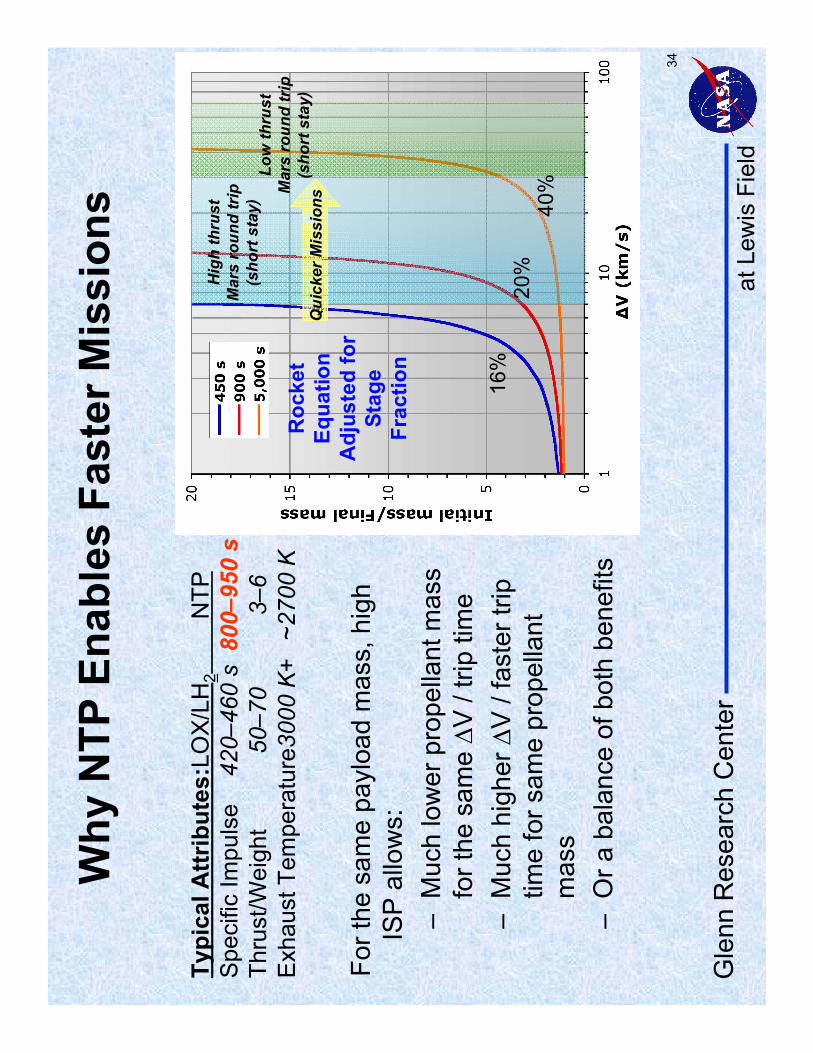
Why
NTP
Ena
bles
Fas
ter M
issi
ons
Typi
cal A
ttrib
utes
:LO
X/L
H2
NTP
Spe
cific
Impu
lse
420–
460
s80
0–95
0 s
Thru
st/W
eigh
t50
–70
3–6
Exh
aust
Tem
pera
ture
3000
K+
~270
0 K
For t
he s
ame
payl
oad
mas
s, h
igh
ISP
allo
ws:
–M
uch
low
er p
rope
llant
mas
s fo
r the
sam
e ∆V
/ tri
p tim
e–
Muc
h hi
gher
∆V
/ fa
ster
trip
tim
e fo
r sam
e pr
opel
lant
m
ass
–O
r a b
alan
ce o
f bot
h be
nefit
s
16%
20%
40%
at L
ewis
Fie
ldG
lenn
Res
earc
h C
ente
r
35
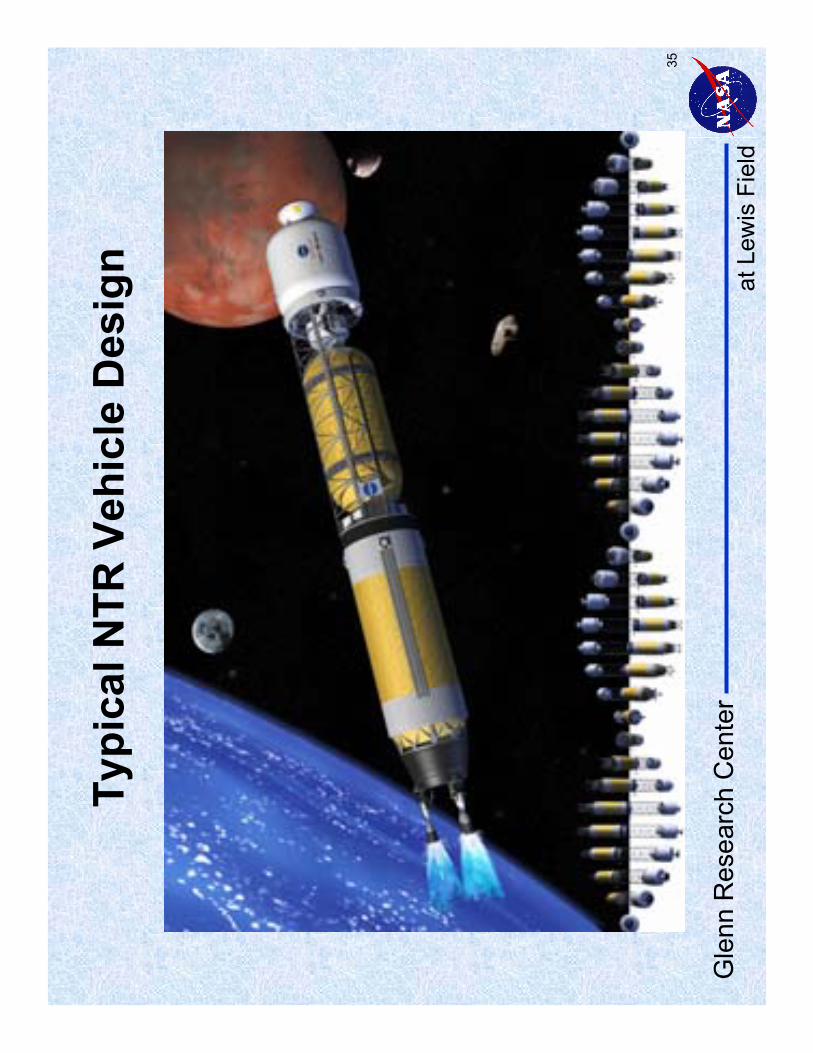
Typi
cal N
TR V
ehic
le D
esig
n


