THE CURRENT PILING CODE AS 2159 -2009 - Australian
42
THE CURRENT PILING CODE AS 2159 -2009 SOME NEW CHANGES AND FEATURES Gary Chapman Golder Associates Melbourne GARY CHAPMAN 9/6/2010 1
Transcript of THE CURRENT PILING CODE AS 2159 -2009 - Australian

THE CURRENT PILING CODE AS 2159 -2009
SOME NEW CHANGES AND FEATURES
Gary Chapman Golder Associates Melbourne
GARY CHAPMAN
9/6/2010 1
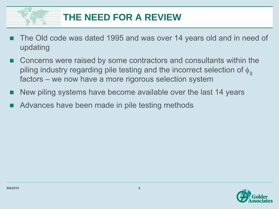
THE NEED FOR A REVIEW
The Old code was dated 1995 and was over 14 years old and in need of updating
Concerns were raised by some contractors and consultants within the piling industry regarding pile testing and the incorrect selection of φgfactors – we now have a more rigorous selection system
New piling systems have become available over the last 14 years
Advances have been made in pile testing methods
9/6/2010 2

SAA COMMITTEE CE 018 MEMBERS
Prof Harry Poulos (chairman)Brian Chandler Dr Gary ChapmanDavid KlingbergPeter Mc Donald (co-opted)Jim MillarProf Mark RandolphDr Julian Seidel Slav TchepakDr Frank Collins
Coffey Geosciences, SydneyAECOM -Maunsell, MelbourneGolder Associates, MelbourneWagstaff Piling, BrisbaneDouglas Partners, MelbourneWaterway Const. SydneyUWAFoundation QA, MelbourneVibropile, SydneyMonash University, Melbourne
9/6/2010 3
OUTLINE OF CHANGES
New terminology – S* is now EdCode structure – similar to previous, new pile types recognised -jacked and steel screwed, cast insitu screw displacementGeotechnical design aspects – φg factor is now calculated not selected from a list, down drag calculations improvedStructural design aspects –durability section revised, revised concrete placement factor Construction and testing aspects – changes to pile testing acceptance criteria, some testing clauses are now normative (i.e. required) rather than there for guidance only, there is now recognition of benefits of testing by increasing the φg factor with increasing amounts of testingTesting aspects recognition of alternative forms of testing such as Statnamic and Osterberg cell tests
9/6/2010 4
Code Structure – Similar to previous with some changes
1. Scope and general2. Site investigation – information required3. Design requirements & procedures4. Geotechnical design- strength and serviceability5. Structural design – concrete and grout piles, steel, composite & timber piles6. Durability design7. Materials and construction requirements8. Testing- revised acceptance criteriaAppendices: Detailed testing procedures and requirements for static, O cell, high strain dynamic, rapid (Statnamic), and low strain and sonic integrity testing
9/6/2010 5
Section 2 - Site Investigations
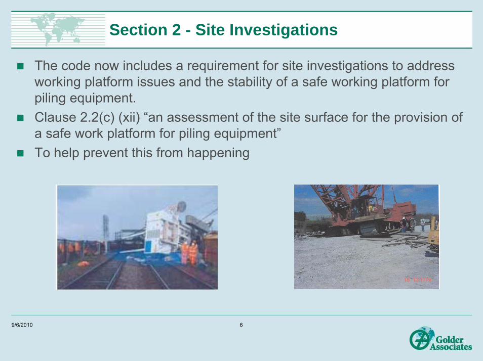
The code now includes a requirement for site investigations to address working platform issues and the stability of a safe working platform for piling equipment.Clause 2.2(c) (xii) “an assessment of the site surface for the provision of a safe work platform for piling equipment”To help prevent this from happening
9/6/2010 6
Section 3 Design Requirements
Design for ultimate strength and for serviceabilityLoad factors for actions from ground movements for structural design
1.2 x negative skin friction (Fnf) action1.5 x compression, tension from vertical ground movement (Fes)1.5 x moment, shear and axial forces from lateral ground movement (Fem)1.5 x moments shears and axial forces from heave due to unloading from excavation (Feh)For geotechnical strength design, loads due to soil movements (e.g. down drag) do not need to be taken into account.For geotechnical serviceability design, loads due to soil movements (e.g. down drag) shall be taken into account using unfactored loads
9/6/2010 7
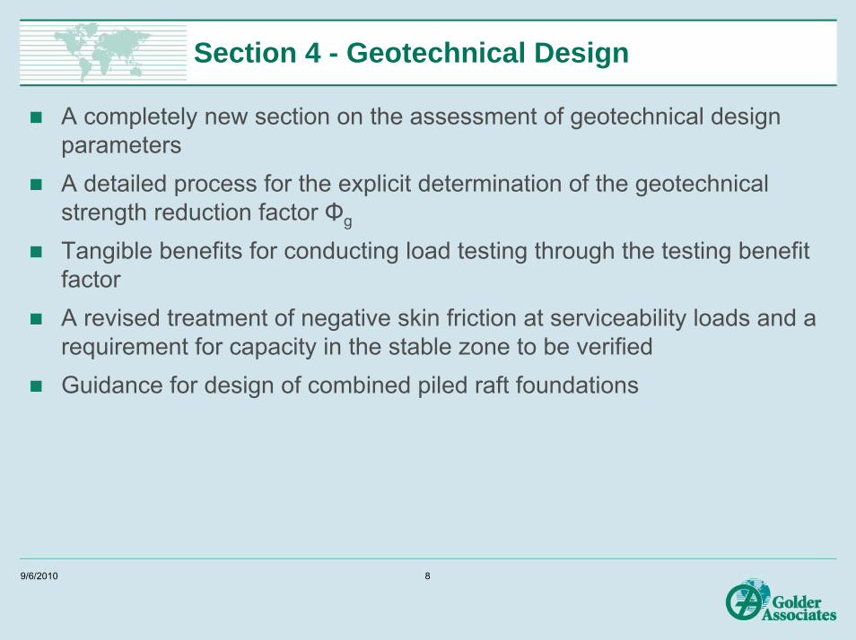
Section 4 - Geotechnical Design
A completely new section on the assessment of geotechnical design parametersA detailed process for the explicit determination of the geotechnical strength reduction factor Φg
Tangible benefits for conducting load testing through the testing benefit factorA revised treatment of negative skin friction at serviceability loads and a requirement for capacity in the stable zone to be verifiedGuidance for design of combined piled raft foundations
9/6/2010 8

Selecting the right geotechnical strength reduction factor
Underlying philosophy:Reduce ad-hoc judgement in the fg selection process available under previous code
Reduced maximum value of fg selection available from 0.9 to 0.76
You must now consider all of the site risks more specifically
There is an incentive for pile load testing by using the testing benefit factor to increase fgCan also allow for the benefits arising from the design of a redundant foundation system. Single piles are not redundant and now attract a reduced fg value – for a low risk site rating fg is 0.67 for a non redundant system versus 0.76 for a redundant system.
9/6/2010 9
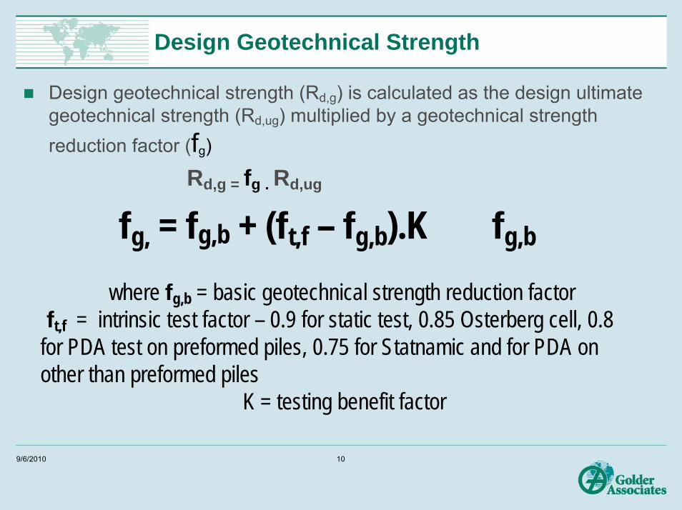
Design Geotechnical Strength
Design geotechnical strength (Rd,g) is calculated as the design ultimate geotechnical strength (Rd,ug) multiplied by a geotechnical strength reduction factor (fg)
Rd,g = fg . Rd,ug
fg, = fg,b + (ft,f – fg,b).K � fg,b
where fg,b = basic geotechnical strength reduction factorft,f = intrinsic test factor – 0.9 for static test, 0.85 Osterberg cell, 0.8
for PDA test on preformed piles, 0.75 for Statnamic and for PDA on other than preformed piles
K = testing benefit factor
9/6/2010 10

Basic Geotechnical Strength Reduction Factor fg,b
The value of fg,b depends upon the assessed site risk factors & the weighted sum of individual risks x risk weighting factors
Risk factors to be considered are divided into 3 categories:Site FactorsDesign FactorsInstallation Factors
9/6/2010 11
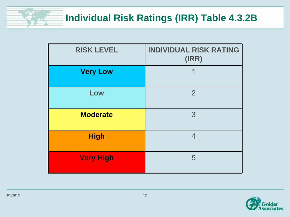
Individual Risk Ratings (IRR) Table 4.3.2B
RISK LEVEL INDIVIDUAL RISK RATING (IRR)
Very Low 1
Low 2
Moderate 3
High 4
Very High 5
9/6/2010 12
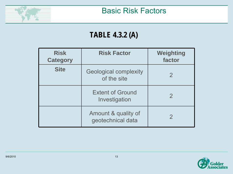
Basic Risk Factors
TABLE 4.3.2 (A)
Risk Category
Risk Factor Weighting factor
Site Geological complexity of the site 2
Extent of Ground Investigation 2
Amount & quality of geotechnical data 2
9/6/2010 13
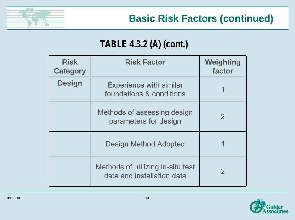
Basic Risk Factors (continued)
TABLE 4.3.2 (A) (cont.)Risk
CategoryRisk Factor Weighting
factorDesign Experience with similar
foundations & conditions 1
Methods of assessing design parameters for design 2
Design Method Adopted 1
Methods of utilizing in-situ test data and installation data 2
9/6/2010 14
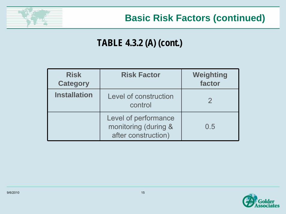
Basic Risk Factors (continued)
TABLE 4.3.2 (A) (cont.)
Risk Category
Risk Factor Weighting factor
Installation Level of construction control 2
Level of performance monitoring (during & after construction)
0.5
9/6/2010 15
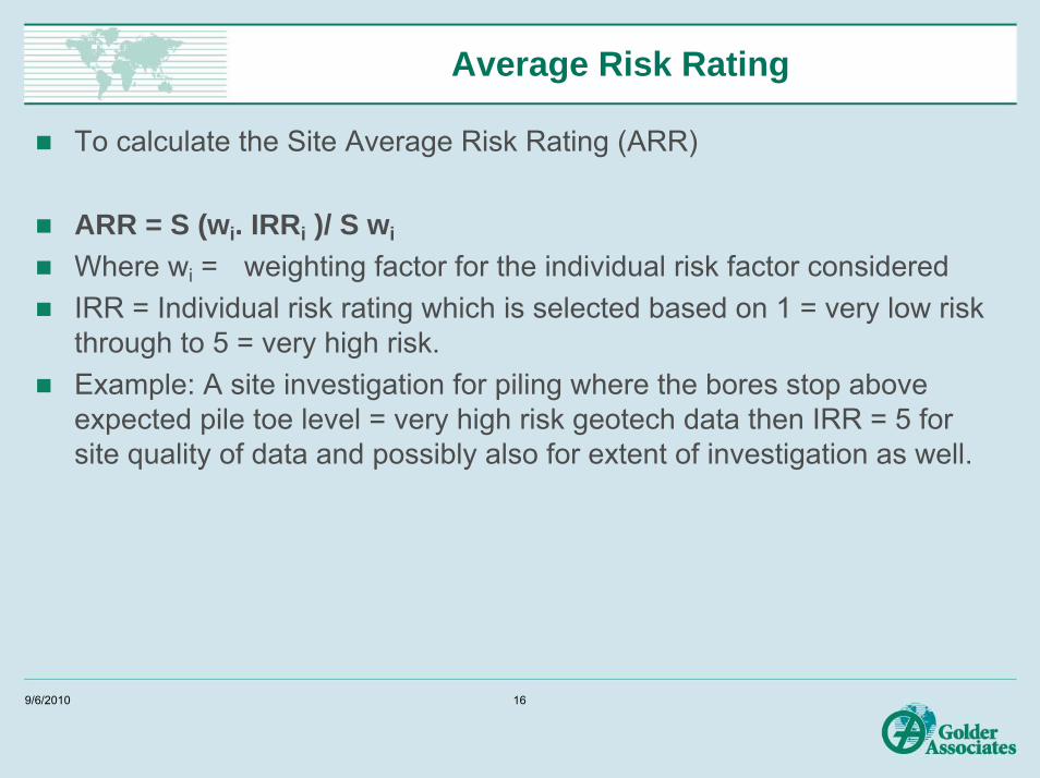
Average Risk Rating
To calculate the Site Average Risk Rating (ARR)
ARR = S (wi. IRRi )/ S wi
Where wi = weighting factor for the individual risk factor consideredIRR = Individual risk rating which is selected based on 1 = very low risk through to 5 = very high risk.Example: A site investigation for piling where the bores stop above expected pile toe level = very high risk geotech data then IRR = 5 for site quality of data and possibly also for extent of investigation as well.
9/6/2010 16
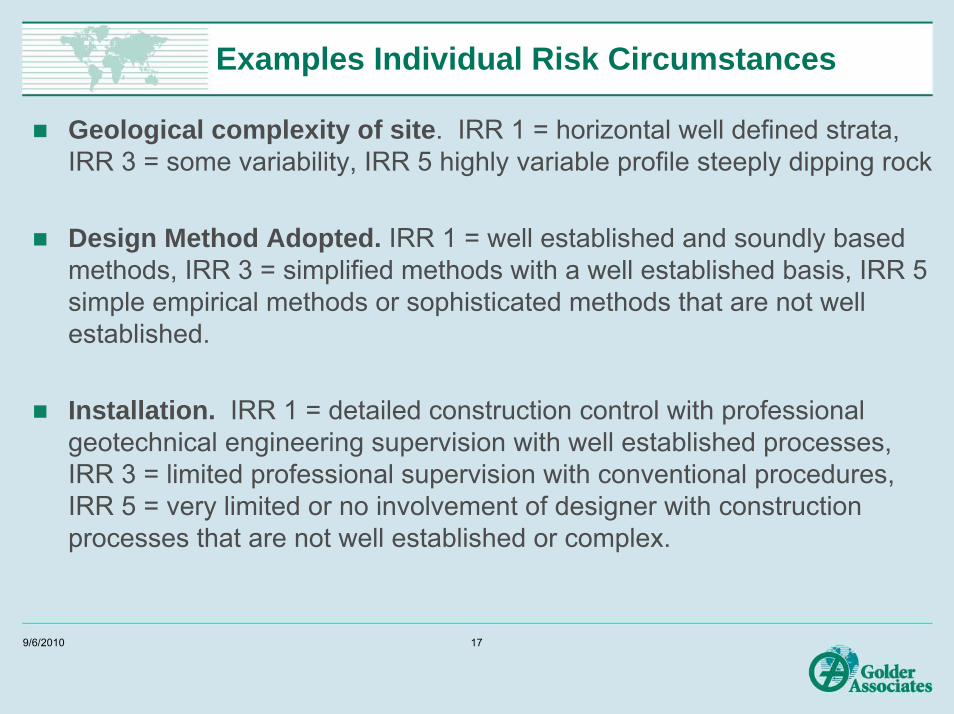
Examples Individual Risk Circumstances
Geological complexity of site. IRR 1 = horizontal well defined strata, IRR 3 = some variability, IRR 5 highly variable profile steeply dipping rock
Design Method Adopted. IRR 1 = well established and soundly based methods, IRR 3 = simplified methods with a well established basis, IRR 5 simple empirical methods or sophisticated methods that are not well established.
Installation. IRR 1 = detailed construction control with professional geotechnical engineering supervision with well established processes, IRR 3 = limited professional supervision with conventional procedures, IRR 5 = very limited or no involvement of designer with construction processes that are not well established or complex.
9/6/2010 17

Sample Average Risk Rating Calculation
Risk Factor (wi) IRR Wi . IRR
Geological Site Complexity 2 3 6Extent of Site Investigation 2 4 8
Amount & Quality of Geotech Data 2 4 8Experience with similar foundations 1 2 2Method of Parameter assessment 2 3 6
Design Method Adopted 1 3 3Method of using Insitu/Install data 2 3 6
Level of Construction Control 2 3 6Level of Performance Monitoring 1 4 4
Sums 15 49ARR = S (wi. IRRi )/ S wi 3.27
9/6/2010 18
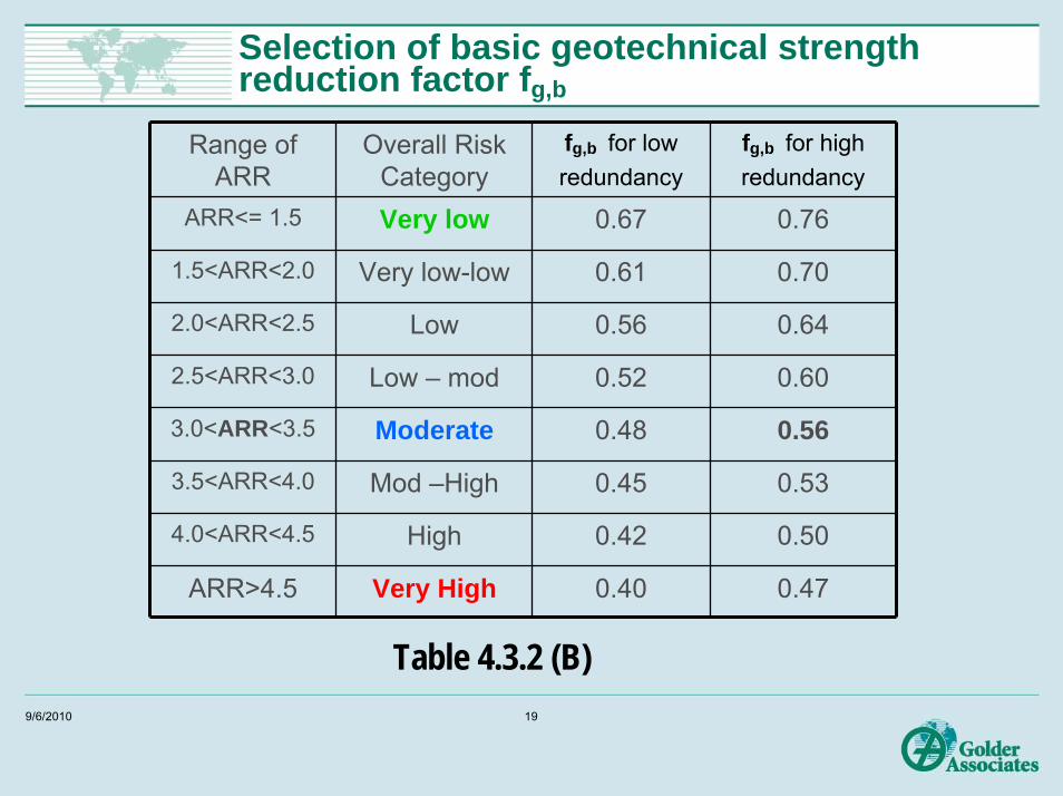
Selection of basic geotechnical strength reduction factor fg,b
Range of ARR
Overall Risk Category
fg,b for lowredundancy
fg,b for highredundancy
ARR<= 1.5 Very low 0.67 0.76
1.5<ARR<2.0 Very low-low 0.61 0.70
2.0<ARR<2.5 Low 0.56 0.64
2.5<ARR<3.0 Low – mod 0.52 0.60
3.0<ARR<3.5 Moderate 0.48 0.56
3.5<ARR<4.0 Mod –High 0.45 0.53
4.0<ARR<4.5 High 0.42 0.50
ARR>4.5 Very High 0.40 0.47
Table 4.3.2 (B)9/6/2010 19

Geotechnical reduction factor - Benefit of pile load testing
fg = fg,b + (ft,f – fg,b).K � fg,b
where fg,b = basic factor (0.56 in this example)
ft,f = intrinsic test factor depends of type of testing
K = testing benefit factor which depends on the amount of load testing carried out
9/6/2010 20
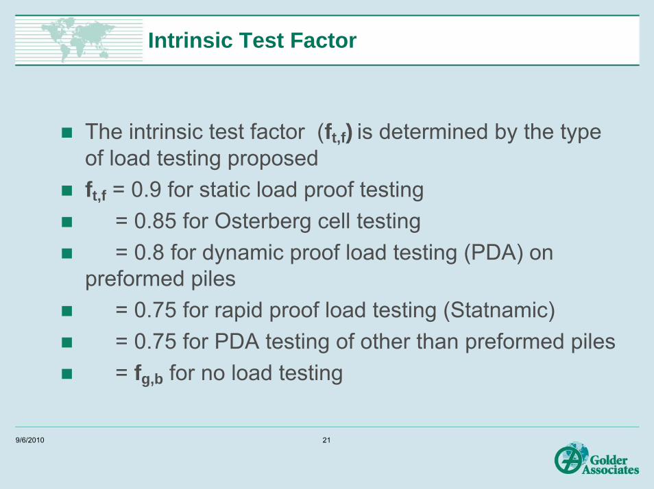
Intrinsic Test Factor
The intrinsic test factor (ft,f) is determined by the type of load testing proposedft,f = 0.9 for static load proof testing
= 0.85 for Osterberg cell testing= 0.8 for dynamic proof load testing (PDA) on
preformed piles= 0.75 for rapid proof load testing (Statnamic)= 0.75 for PDA testing of other than preformed piles= fg,b for no load testing
9/6/2010 21

Testing Benefit Factor K
For static, O cell, or rapid load testing
K= 1.33 p / (p + 3.3) <= 1
For dynamic load testing
K = 1.13 p /(p + 3.3) <=1
where p = percentage of the total number of project piles that are tested and meet the specified acceptance criteria
9/6/2010 22
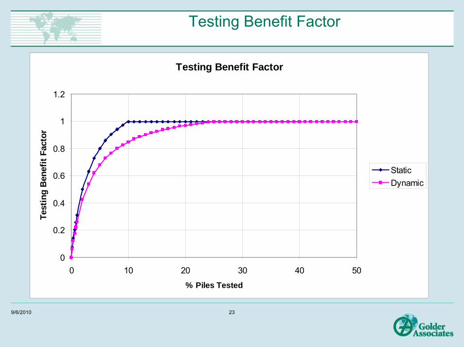
Testing Benefit Factor
Testing Benefit Factor
0
0.2
0.4
0.6
0.8
1
1.2
0 10 20 30 40 50
% Piles Tested
Test
ing
Ben
efit
Fact
or
StaticDynamic
9/6/2010 23

Improvement in fg,d with percentage of piles tested
0.5
0.55
0.6
0.65
0.7
0.75
0.8
0.85
0.9
0.95
0 5 10 15 20 25 30
Phi g
d
% Piles Tested
Geotechnical Strength Reduction FactorTest Benefit Factor
Static Testing
Dynamic Testing
9/6/2010 24

Combined Pile-Raft Foundations
Geotechnical Strength CriterionApplies to the group as a whole and is the sum of the factored strength of the shallow footing fgs Rd,ug,sshallow footing plus fg Rd,ug piles
ServiceabilityRequires an analysis which takes into account the interaction amongst the piles, the raft or shallow footing and the soil. Usually a 2 or 3D FE analysis.
9/6/2010 25
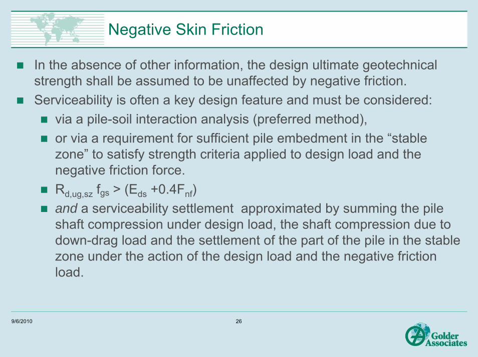
Negative Skin Friction
In the absence of other information, the design ultimate geotechnical strength shall be assumed to be unaffected by negative friction.Serviceability is often a key design feature and must be considered:
via a pile-soil interaction analysis (preferred method),or via a requirement for sufficient pile embedment in the “stable zone” to satisfy strength criteria applied to design load and the negative friction force. Rd,ug,sz fgs > (Eds +0.4Fnf)and a serviceability settlement approximated by summing the pile shaft compression under design load, the shaft compression due to down-drag load and the settlement of the part of the pile in the stable zone under the action of the design load and the negative friction load.
9/6/2010 26
Section 5 - Structural Design
Design Structural Strength is given by:Rd,s = fs k Ru,s
fs is taken from the appropriate code for concrete, steel, timberk = concrete placement factor varies from 0.75 to 1.0 as per Table 5.3.2k value depends on pile type, construction methods and the level of integrity testing and construction monitoring K = 1.0 requires at least 5% integrity testing over full depth of shaft, full installation monitoring of CFA piles, monitoring of drilling fluid for bored piles, monitoring of drive stresses for precast piles.If integrity testing cannot “see” over the full depth of pile consider using a k value of <1For grout piles design using “equivalent” cylinder strength of 0.81 x cube strength
9/6/2010 27

Structural Design
Precast reinforced concrete piles shall have a longitudinal reinforcement area of not less than 0.014Ag. This means 350 mm square precast piles require 4 No. 24 mm bars (0.0147), not 4 No. 20 mm bars (0.1026)For other than precast piles, minimum steel area of 0.005 Ag. (as before)Partially reinforced piles can have reinforcement curtailed one development length below the level in the pile when bending and tensile loads cease to be significant and when the design axial load in the unreinforced section of the pile does not exceed 0.5 k f’cAg fsUnreinforced piles are permitted where the design action effect does not exceed 0.45 k f’cAg fsFor cast in place screw piles design using minimum shaft cross section
9/6/2010 28

Section 6 - Design for Durability
Exposure classification for concrete piles is unaltered
Greater reinforcement cover for cast-in-place piles
Now have a provision of 50 and 100 year design life cover
Steel piles now have separate exposure classifications for water, refuse fill and soil
Steel pile “very severe” exposure corrosion allowance lower limit increased to 0.1 mm/yr
9/6/2010 29
Section 7 - Material & Construction Requirements
Position. Revised position tolerances now avaiable for piles with deep cut off levelsNon circular piles where axis orientation is specified have10 degree limitInstallation by jacking
Follows Chinese code requirements (inventors of the system)Requirements on the installation force to be used Pmax =0.74 γpRug where γp is the coefficient of jacking pressure assessed from static test correlations but not less than 1.4.If no correlations are available take γp as 1.5 for piles>15m, 1.75 for 8 m- 15 m and 2.2 for piles < 8m long Repeated jacking required (minimum of 5 repeats)Installation by jacking IS NOT considered to be equivalent to a static load test
Installation by screwing - new section9/6/2010 30

Pile Load Testing – Significant Changes here
9/6/2010 31
Section 8 - Pile Load Testing
Pile testing is encouraged Testing benefit factors reward testing with higher fg factorsWhere φg,b is 0.4 or less no testing is required unless specifiedWhere φg,b is > 0.4 then testing is mandatory (normative).
In absence of tests the verify design ultimate geotechnical strength tests for serviceability are required for all sites with an ARR > 2.5.Percentage of piles to be serviceability load tested varies with ARR
ARR 2.50 - 2.99 Test 1% of piles3.00 - 3.49 2%3.50 - 3.99 3%4.00 – 4.49 5%
>= 4.5 10%
9/6/2010 32

Integrity Testing Table 8.2.4 B
Testing of integrity shall be conducted in accordance with Table 8.2.4(B)Amount of integrity testing (5% to 25%) depends on
Whether the pile design load is governed by pile geotechnical capacity or pile shaft structural capacityThe method of pile constructionConstruction control and monitoringIntegrity test method must be capable of verifying the integrity of the full length of pile shaft which may preclude the use of low strain head impact methods for long pilesNeed to consider all of the factors in Table 8.2.4 (B) in selecting the percentage of piles to be integrity tested
9/6/2010 33

Determination of Test Load
Default test load values for sites without negative skin friction are nominatedLoads for assessment of ultimate geotechnical strength
Pu = Ed/fg,d for compression or 1.2 Ed for tension or lateral loading
Load for assessment of serviceabilityPs = Ed,s
Load for assessment of design geotechnical strengthPg = Ru,g
9/6/2010 34
Determination of Test Loadwith negative skin friction
Maximum test load shall take into account the required ultimate pile strength in the stable, non down drag zone
Test load shall also include allowance for shaft resistance through settling ground that will provide positive support during the short duration of the load test but produce long term negative skin friction
9/6/2010 35
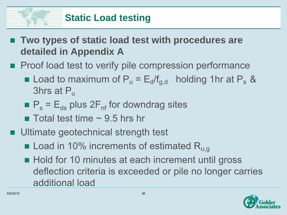
Static Load testing
Two types of static load test with procedures are detailed in Appendix AProof load test to verify pile compression performance
Load to maximum of Pu = Ed/fg,d holding 1hr at Ps & 3hrs at Pu
Ps = Eds plus 2Fnf for downdrag sitesTotal test time ~ 9.5 hrs hr
Ultimate geotechnical strength testLoad in 10% increments of estimated Ru,g
Hold for 10 minutes at each increment until gross deflection criteria is exceeded or pile no longer carries additional load
9/6/2010 36
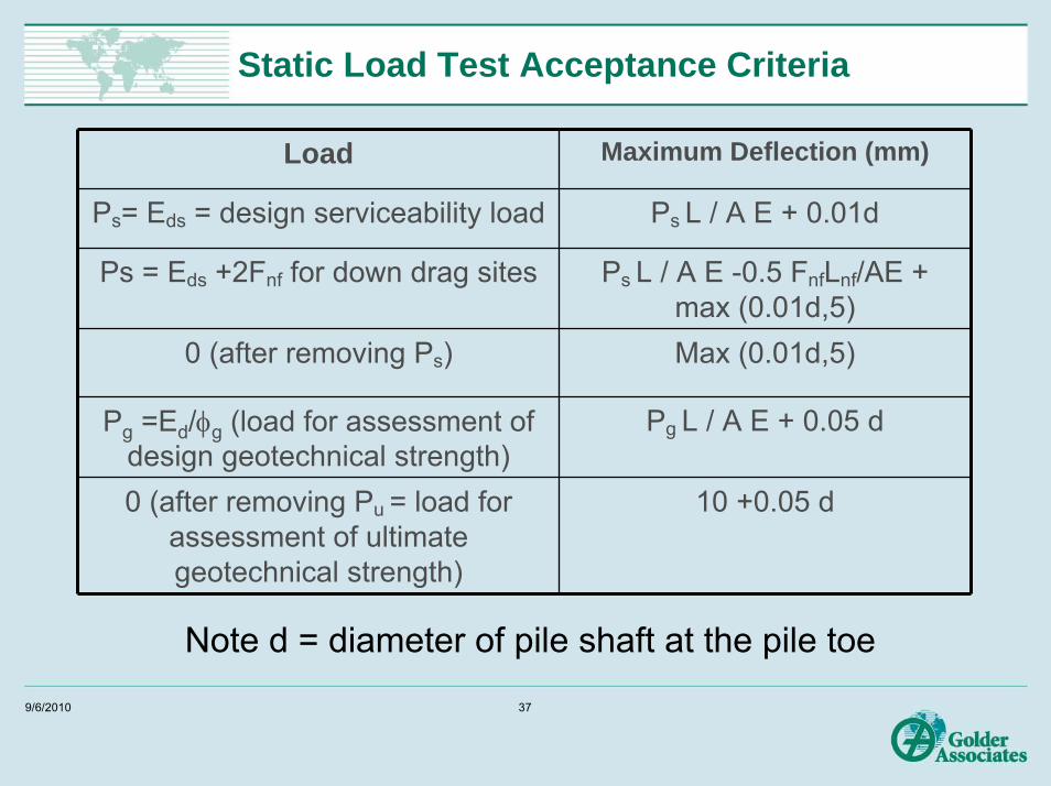
Static Load Test Acceptance Criteria
Load Maximum Deflection (mm)
Ps= Eds = design serviceability load Ps L / A E + 0.01d
Ps = Eds +2Fnf for down drag sites Ps L / A E -0.5 FnfLnf/AE + max (0.01d,5)
0 (after removing Ps) Max (0.01d,5)
Pg =Ed/φg (load for assessment of design geotechnical strength)
Pg L / A E + 0.05 d
0 (after removing Pu = load for assessment of ultimate geotechnical strength)
10 +0.05 d
Note d = diameter of pile shaft at the pile toe
9/6/2010 37
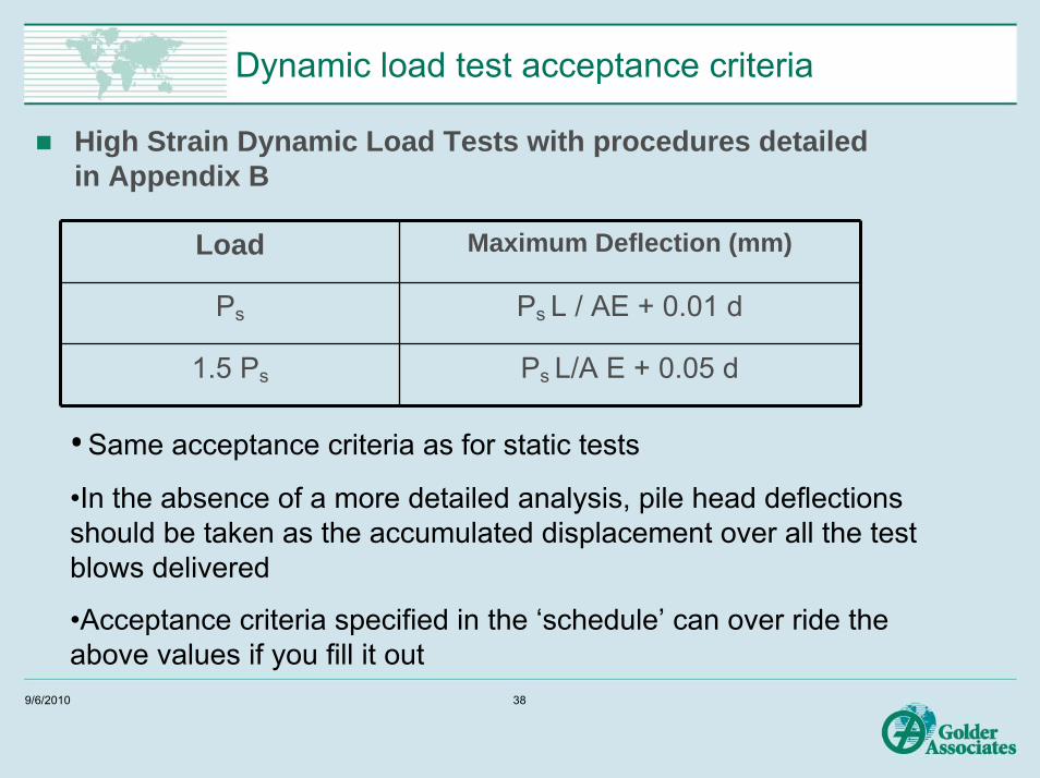
Dynamic load test acceptance criteria
High Strain Dynamic Load Tests with procedures detailed in Appendix B
Load Maximum Deflection (mm)
Ps Ps L / AE + 0.01 d
1.5 Ps Ps L/A E + 0.05 d
• Same acceptance criteria as for static tests
•In the absence of a more detailed analysis, pile head deflections should be taken as the accumulated displacement over all the test blows delivered
•Acceptance criteria specified in the ‘schedule’ can over ride the above values if you fill it out
9/6/2010 38

Assessment of dynamic test results
9/6/2010 39
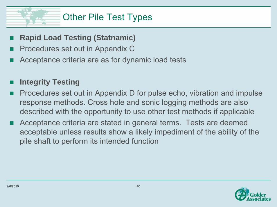
Other Pile Test Types
Rapid Load Testing (Statnamic)Procedures set out in Appendix C Acceptance criteria are as for dynamic load tests
Integrity TestingProcedures set out in Appendix D for pulse echo, vibration and impulse response methods. Cross hole and sonic logging methods are also described with the opportunity to use other test methods if applicableAcceptance criteria are stated in general terms. Tests are deemed acceptable unless results show a likely impediment of the ability of the pile shaft to perform its intended function
9/6/2010 40

Overall Objectives of Code
To improve the standard of pile design and constructionDesign is to include a detailed consideration of risk factors To encourage pile testing by:
Recognising design benefits arising from testingTo require load testing in some circumstancesTo require integrity testing in some circumstances
To encourage the monitoring of pile performance, both during and after pile installation
9/6/2010 41

Thank You!!
Questions (?s)and
Answers (!!!s)
9/6/2010 42