The Best Grade for Turning, Milling and Drilling · PDF fileThe Best Grade for Turning,...
64
2017 www.iscar.com Robust Structure, Concave Cutting Edge Design, Drilling at High Feed Rates = Accurate Hole Tolerance and Quality!
-
Upload
nguyenphuc -
Category
Documents
-
view
225 -
download
3
Transcript of The Best Grade for Turning, Milling and Drilling · PDF fileThe Best Grade for Turning,...

The
Best
Gra
de f
orTu
rnin
g, M
illin
g an
d D
rillin
g
2017
www. iscar.com
Robust Structure, Concave Cutting Edge
Design, Drilling at High Feed Rates = Accurate
Hole Tolerance and Quality!

High-Q Tools for Machining Intelligently 4
Faster & Much Faster 6
Quantum Leaps & Steady Progress 14
Multi-Mastering New Applications 22
Drilling Profile Construction Beam 26
Turbine Production 30
ISCAR ‘Automotive-ated’ to Provide Advanced Tooling Solutions 36
Turnmilling Kinematics 48
The Power of Seminars 54
Advanced Vending Systems for Higher Productivity 55
Are Trade Shows Worth It In the Digital Age? 60
Table of Contents

ISCAR invests 6% of its annual turnover in research and development.
ISCAR Production
ISCAR R&D
ISCAR QA
ISCAR Marketing

4
What is the IQ of a cutting tool? When talking about artificial intelligence, we usually mean various man-made products such as robots and software systems. Is it correct to connect IQ to cutting tools? In many ways yes it is! The cutting tool, a small item in terms of both investment and dimensions relating to a manufacturing process. Although the cutting tool plays a major role in improving productivity and enabling cost reductions;
Indeed, the cost of tools are not in the same expense league as modern CNC machining centers featuring technological options that can exceed all expectations. However, when purchasing expensive machines, the manufacturer looks to their maximal load ratio: ideally nonstop cutting throughout 24 hours! Here suddenly attention is drawn to the tool – this tiny little link may be a reason of unwelcome lost time. Hence, users require tools that are very reliable and have a predictable tool life, and, if possible, meet the requirement of little or no setup time. Furthermore, the correct tool ensures easy cuts and vibration free machining. The results are obvious: less power consumption and reduced machine wear.
The right tool uses progressive tool materials that provide increasing cutting speeds and productive cutting. At the same time, the right tool enables efficient chip evacuation necessary for high metal removal rates.The chosen tool needs to enable the successful machining of difficult-to-cut materials that are constantly being introduced in the design of modern products.
When applicable, the right tool should be suitable for machining hard workpieces. This feature provides the possibility to replace secondary processes such as grinding.
HIgh-Q Tools for Machining Intelligently

5
So, when inspecting closer, this small link becomes very important. Producing a tool that answers multiple purposes is a challenging task. The solution - a tool that reflects the IQ of its creators: researchers, designers, manufacturers. Every new generation of cutting tools that makes a breakthrough in technology, or seriously contributes to reducing production costs, becomes more intellectual. At ISCAR, we learn and understand the demands of our customers.
With the use of the advanced IQ, leading-edge tools and the application of ‘“Machining Intelligently!” customers are able to considerably boost productivity, improve quality standards and increase profitability. We, the tool manufacturer, pride ourselves in our cooperation with our customer in this work. We believe in productive partnership and know from experience that this collaboration is very fruitful for both parties.

6
The remarkable progress made in the area of rough milling in the 1990’s saw the introduction of fast feed (FF) and high feed milling (HFM). These highly efficient methodologies overturned established views and brought radical new ideas to the field.
Rather than use the traditional high metal removal technique – milling with considerable depths and widths of cut – users of the new approach continued to machine with similar width of cuts, although they used a much smaller depth of cut and applied much faster speeds with substantially increased feed per tooth.
Milling with a large axial depth of cut (DOC) requires the kind of cutting force provided by high-power machine tools, whereas FF roughing with shallow DOC needs a lot less machine power, although the cutting tool should run fast. Therefore, light-duty machines featuring axis drives with sufficient velocity are sufficient for FF milling.
Energy saving shallow-cut “fast” technology provides an excellent alternative to power consuming deep-cut methods. Impressive high metal removal rates (MRR) at reduced power input is not the only advantage of the strategy, FF milling delivers two additional benefits. Shallow DOC enables contours to be produced that are very close to the final required shape of a machined surface, reducing or even eliminating semi-finish passes. In addition, the small cutting edge angles of FF milling cutters
Faster & Much Faster
NEW

7
allows considerable increases in feeds and speeds per tooth (fz) due to the effect of chip thinning.
This advantageous geometry minimizes the radial effect of the cutting force and maximizes its axial influence, resulting in forces that act towards the spindle axis, i.e. the direction of maximum machine tool rigidity. The result - improved milling stability, reduced vibrations, prolonged tool life, reduced power consumption and increased productivity.
Although FF strategies began in the area of indexable milling, it soon extended to solid carbide endmills and became popular in the global die and mold making industry due to its efficiency when machining complicated shapes and cavities, especially of small sizes. Due to diverse and frequent changing working programs, their fast low-power machining centers and advanced CAD/CAM software, die and mold producers quickly saw the value of the new strategy.
Although carbide endmills were the most commonly used cutting tool, FF milling cutters of relatively small diameters were also very popular prior to the introduction of the new strategy. Subsequently, the FF approach came into fast feed facing (“triple F”) and opened the way to the development of various indexable face milling cutters. Now, given the amount of face milling that takes place in this major global area, general engineering is the main consumer of these tools.
Fast Feed Milling CuttersThese milling cutters are a key factor in fast feed milling techniques. The cutter geometry, designed for efficient chip thinning, needs to ensure correct distribution of the cutting force components. There are two principal geometrical approaches. The first design requires the cutting edge of an FF milling cutter to be an arc of a great circle. Another concept is based on using one or two straight edges that are chords of the arc. In both cases, the small cutting edge angle

8
(usually 10-17°) meets the requirements of chip thinning and total cutting force. Ensuring the geometry of solid carbide fast feed endmills and replaceable milling heads demands the specific shape of a cutting edge, while in indexable milling it may be provided by the appropriate location of an insert of even simple profile.
Although the introduction of innovative carbide grades and advances in the form of rake faces has further improved progress in FF milling cutters, the essential element of fast feed milling – geometry – remains constant.
Chip thinning due to the cutting edge of a FF milling cutter is the arc of a great circle (or the chords that approximate the arc), making the cutter a toroidal tool. The latter being rotated around their axis produces a torus or ring-shape. A typical representation of a toroidal tool is a milling cutter carrying round (button) inserts.
The cutting edge angle of the cutter is not a constant value but it varies depending on the axial depth of cut from 0 to 90°. Decreasing depth reduces the cutting edge angle resulting in thinner chips. The programmed feed per tooth for a cutter with round inserts relates to the maximal diameter of the cutter, i.e. to the maximal depth of cut (it is equal to the insert radius) and the maximal cutting edge angle. But if the cutter mills under the maximal depth, the chip is thinner; and therefore the programmed feed should be increased correspondingly in order to produce the chips of required thickness. The same situation is observed in ball-nose milling tools, and explains why FF cutters run so fast. ISCAR offers a wide variety of fast feed milling families that represent different classes of indexable tools, solid carbide endmills and solid carbide interchangeable heads with Multi-Master threaded connections.
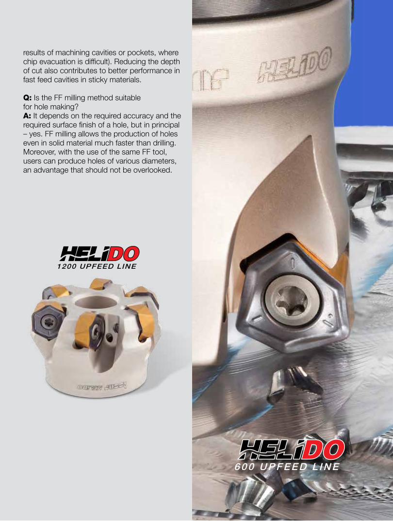
A popular example is the ISCAR HELIDO 600 UPFEED LINE, a real workhorse for fast feed milling. Although this commonly used tool

9
was launched several years ago, it has been continuously updated and upgraded. The key element of this family is the H600 WXCU Trigon double-sided insert with 6 cutting edges - an ISCAR patented design. The cutting edge of the insert comprises two sections: the main (external) and the minor (internal) cutting edges. While the main edge produces 17° cutting edge angle, the minor edge plays an important role in ramping down and makes a significant contribution to improving the performance of the tool.
The carefully designed rake face of the insert, in which the portion adjacent to the main edge is convex; and the portion adjoining the minor edge is concave, ensures effective chip formation and directs chip flow away from the cutter. This arrangement drastically reduces re-cutting and considerably increases tool life when the cutter mills deep cavities and pockets.
The adjacent portions of the side surface of the insert have opposite inclinations. This provides the necessary relief for the right cutting edge and ensures the insert’s rigid clamping in a dovetail-shape pocket. The illustrated beneficial design features of the HELIDO 600 UPFEED LINE ensure great efficiency in FF milling for a wide-spectrum of applications: machining planes, 3-D surfaces, slots and cavities and explains the continuing popularity of the family.

10
ISCAR’s FEEDMILL family has recently been expanded by the introduction of FFQ4 shell mill cutters. The cutters are intended for mounting square single-sided inserts with 4 cutting edges.
Triple F - fast feed facing - perfectly describes the main applications of the new mills, while the FFQ4 delivers productive roughing of plane surfaces especially if the mill overhang is high. If a fast feed milling cutter of a small diameter (6-20mm) is needed, the use of a solid carbide or MULTI-MASTER tool leads to good results. The design of the tools allows the production of a cutter with more teeth when compared with an indexable FF mill of the same diameter, ensuring improved productivity.
There are two kinds of the MULTI-MASTER fast feed heads; the first a multiflute design which is similar to the solid carbide FF tools. The second, an economical version, has only two flutes, however, due to these two flutes being “shaped” by pressing with further sintering, they feature high strength. In contrast to the multiflute heads, this enables increase fz to achieve the necessary metal removal rate (MRR). In addition, all FF tools also have side plunge-in milling capacity providing impressive wall surface finish and a flat bottom during machining. Users can successfully apply the tools to the sculpturing of various internal and external shapes.
When fast feed milling became popular and adopted throughout industry, manufacturers asked, is it possible to “adjust” commonly used indexable cutters for the more productive technique of rough machining? The question was particularly relevant for small manufacturers who were uninterested in purchasing specific FF tools. ISCAR supplied the required answer by offering carbide inserts that, when mounted in existed cutters, turned them into FF mills (Fig. 7). This innovative approach expanded the operational range of customers stock cutters. Another versatile approach involved the application of a regular insert for fast milling: In this method, the insert should be oriented differently and held in a cutter suitable for the high-efficiency FF technique. This principle is reflected in FF SOF 8/16 tools, intended for “triple F” – fast feed facing.
Heavy workpieces have their own demands. When milling the workpieces, considerable inertial loading on the feed drive places restrictions on the table feed. The same limitations take place when workholding is poor. In these cases customers cannot take full advantage of FF milling. A solution is to moderate the fast feed and simultaneously increase the depth of cut. The secret is to find the most efficient compromise. Fz should be higher than common values but the produced feed speed (known also as table feed, feed per minute

11
or feed rate) will meet possibilities of the feed drive. Also, the power consumption should not be too high. The method, MF – moderate feed milling, lies between traditional rough milling and the FF technique. And again, the milling cutter is a key player in this process.
The cutting edge angle of an MF milling tool is approximately 30°, an increase when compared to FF tools. This reduces fz and maintains the necessary chip thickness but allows greater depths of cut, hence metal removal rates remains high. The increased cutting power is less of a problem for the heavy-duty main drives, therefore moderate feeds in combination with the appropriate tool geometry provides the necessary results. There are two types of ISCAR MF cutters. The HELIDO 600 UPFEED has different design configurations: endmills, face mills and replaceable milling heads with a thread connection for the FLEXFIT system.

12
In common with the aforementioned FF cutters, they also carry the H600 WXCU inserts – another example of customer-friendly versatility - the same insert is mounted in two functionally different kinds of milling tools.
The second type of MF cutters is the HELIDO 1200 UPFEED: this range of face mills with double-sided hexagonal inserts has 12 cutting edges. The cutters are intended for productive milling plane surfaces and have the ability to machine near to the straight wall of square shoulders. High MRR and cost effectiveness per insert cutting edge make the cutters an attractive tool for upgrading low power machines to triple F.
In consideration of fast feed milling and its moderated derivative, the main applications are:
In the majority of cases that are connected with the listed applications, the smart decision of introducing fast milling into a process significantly improves productivity and cuts production costs.
Q: Can fast feed milling be applied to high temperature alloys, in particular to titanium?A: Definitely yes, on condition that the tool (cutting geometry, carbide grade) and the cutting data are chosen correctly. For example, when FF milling titanium alloys by HELIDO 600 UPFEED indexable milling cutters, HP-type inserts should be used and the recommended starting feed per tooth employed.
Q: Can we operate a fast feed tool for rough milling a full slot?A: Yes, however, the cutting speed and the feed per tooth should be reduced when compared with the usual recommended values for the machined material.
Q: Is FF milling suitable for hard steels?A: Yes, but substantial reductions in the feed per tooth starting values of fz will be in average 3-4 times less compared to the soft steels.
Q: A virtual “radius for programming” of a FF tool is specified in catalogues and guides, what does this mean A: FF tools have a specific shape that differs from ordinary milling cutters. For CNC programming purposes users may consider the tool like a cutter with a corner radius.
Q: When milling, the high overhang of a tool normally requires reduced cutting speed and feed per tooth. Is it true for the FF technique?A: Regarding the speed – yes; and speaking about the feed, although, our experience shows that rather than reduce feeds, a more effective method is to reduce the depth of cut and operate at the unchanged fz. This not only improves the stability of the tool and enhances chip evacuation, it also reduces recutting (in many cases the high tool overhang is a direct
• rough face milling especially if a machining allowance (material to be removed) is high and a machined surface has relatively big dimensions
• rough milling of cavities and pockets • sculpturing by side plunging
Questions & Answers
13
results of machining cavities or pockets, where chip evacuation is difficult). Reducing the depth of cut also contributes to better performance in fast feed cavities in sticky materials.
Q: Is the FF milling method suitable for hole making?A: It depends on the required accuracy and the required surface finish of a hole, but in principal – yes. FF milling allows the production of holes even in solid material much faster than drilling. Moreover, with the use of the same FF tool, users can produce holes of various diameters, an advantage that should not be overlooked.

14
The ascent of the carbide insert is characterized by revolution and evolution. Cemented carbide is a hard material that is used extensively in cutting tools intended for machining.
Within an industrial context, references to carbide or tungsten carbide usually refers to cemented composite. Carbide cutters deliver many advantages, in the vast majority of cases, they provide a better surface finish on the machined part, and allow faster machining when compared to the use of high-speed steel (HSS) cutters. In addition, carbide tools are able to withstand higher temperatures at the cutter-workpiece interface than standard high-speed steel tools, the principal reason for their faster machining capability.
Carbide usually provides superior performance for the cutting of tough materials such as high alloyed steel or stainless steel, as well as in situations where other cutting tools would wear faster, such as when performing high-quantity, extended production runs. Industries use of cemented carbide for cutting metals began in the 1930s. Since that time carbide has become by far the most popular material for the production of cutting tools. While some tools that feature relatively small sizes are wholly produced from carbide; others use carbide at the cutting area only. Originally the cutting area consisted of a carbide tip that was brazed or soldered to a tool body. However, in the 1940s cutting tool manufacturers began producing cutting tools with the advantage of replaceable carbide segments that were mechanically mounted on to the tools body.
This clever innovation and the use of mechanical clamping, which provides much greater strength when compared with the previously brazed connections, are now recognized as memorable milestones, not only in the area of tool manufacturing, but also in advancing the efficiency of all metalworking industries.
This major development led to impressive improvements in productivity within the area of machining operations. It was immediately possible
Quantum
Leaps & Steady Progress

15
to increase the load on the tool and to improve metal removal rates. In addition, this cost effective innovation ensured the simple and economical replacement of the cutting element when worn or in case of breakage. It also allowed the manufacturing of cutting segment and the tool bodies to be separated.
Depending on the shape of the inserts used, they could be quickly indexed ensuring the rapid change of a worn cutting corner by several methods, such as rotating the insert on its axis or by flipping it upside down. Initially the new cutting segments were known by several names, such as throwaway tips, interchangeable inserts and replaceable inserts. However, today the more widespread, generic term - indexable inserts - is used.
The technology used in the manufacturing of the indexable inserts is based on powder metallurgy, comprising of several manufacturing processes. Progress in science and technology has significantly impacted on the manufacturing process of inserts. In the past, inserts were produced by the use of manual machines. Hence, the application of various complex powder metallurgical processes was very difficult or even impossible to perform. The introduction of more progressive industrial equipment, featuring advanced automation and computer control, made the technological processes more stable, controllable and reliable, including:
Consequently, the mechanical properties of manufactured inserts became more uniform, predictable and repeatable; these factors allowed dramatic improvements in terms of the accuracy of sintered inserts by reducing production tolerances. Today, a typical insert production press is a highly engineered device that is computer controlled. A moveable punch
• preparing carbide powder (mixing)• pressing the powder (compacting)• sintering compact• post-sintering processing• coating

16
can be made from several “sub punches”, each operated separately. Some press designs encompass multi-axial pressing options.
The remarkable progress in press technology enables the production of complex shaped inserts that are characterized by variable corner heights. (fig.1) This capability enables optimal cutting geometries to be achieved, guaranteeing not only smooth and stable machining but also the increased accuracy of a machined surface. (fig.2)
Additionally, the advantages provided by the use of modern CAD/CAM systems make it possible to improve the design and the shaping parts of pressing die sets. Also, the ability to simulate the pressing processes related to new sintered products, when they are at the beginning of their design stages, allows further design amendments and enhancements to be made.
Advanced new techniques, related to sintering insert masters, improves process quality. The gradient sintering of multi-carbide substrate ensures a thin upper layer that feature high cobalt content. This gradient layer produces an excellent barrier against the development of cracks and
Fig.1. ISCAR's H690 TNKX 1005 milling insert featuring different corner heights
Fig.2. Accurate and smooth machining
Fig.3. Nanolayer structure of ISCAR's IC807 carbide grade coating - SEM image
17
guarantees increased resistance to brittleness and fracturing. Today, substrates of this type are commonly used in tools intended for turning operations. Until the 1980s carbide grades were uncoated. In order to make grades more universal and applicable to machining various engineering materials, tool manufacturers developed grades that contained various additives. The adoption of coating technologies has dramatically changed the world of machining; now the vast majority of carbide grades are coated. The inclusion of this new technology permitted the grades to focus on cutting specific material groups. The substrates contained fewer additives; therefore their structures became more uniform and stable, which further improved control during production.
The introducing of coated carbides and on-going developments in this area has enabled significant increases in cutting speeds.
For example 30 years ago, when turning grey cast iron the cutting speed used was approximately 100 m/min for inserts which were made from IC20 (ISCAR uncoated
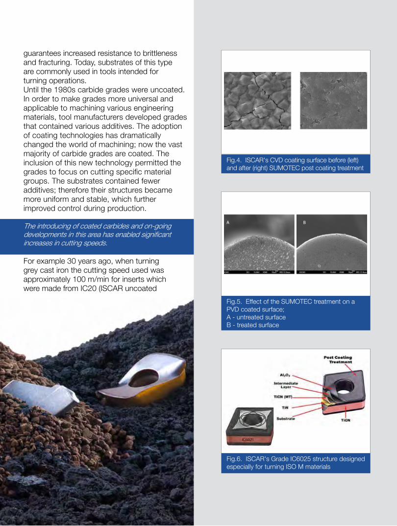
Fig.4. ISCAR's CVD coating surface before (left) and after (right) SUMOTEC post coating treatment
Fig.5. Effect of the SUMOTEC treatment on a PVD coated surface;A - untreated surfaceB - treated surface
Fig.6. ISCAR's Grade IC6025 structure designedespecially for turning ISO M materials

18

19
carbide grade). Today, the coated IC5005 allows speed values of up to 600 m/min. In another case, the milling of martensitic stainless steel during the same years was performed at about 80 m/min for IC50M (ISCAR uncoated carbide grade), now 300 m/minis the acceptable value when using IC5500 (ISCAR coated grade).
These impressive numbers provide an excellent illustration of how coated carbides have allowed leaps in progress to be made in the area of cutting speeds.
Coating technology continues to develop in two principal directions – Chemical Vapor Deposition (CVD) and Physical Vapor Deposition (PVD). The main result of progress within the area of CVD was the introduction of Alumina ceramic coatings. This allows machining at elevated speeds due to its excellent temperature isolation properties, high hardness and chemical stability at high temperatures.
PVD coatings were introduced during the late 1980s. PVD coatings performed a gigantic step in overcoming the complex problems that prevented progress within the field of nanotechnology. PVD coatings brought a new class of wear-resistant Nano layered coatings. Such coatings (fig.3) are a combination of layers having a thickness of up to 50 nm (nanometers) and demonstrate significant increases in the strength of provided by coatings when compared to conventional methods.
Modern technology allows both methods – CVD and PVD – to be combined for insert coatings, as a means of controlling coating properties. In particular, ISCAR’s carbide grade DT7150 features a tough substrate and a dual MT CVD and TiAlN PVD coating. This was originally developed to improve the productive machining of special-purpose hard cast iron. Another major advancement in insert technology relates to post-coating treatments. For instance, ISCAR developed SUMOTEC, a treatment method for the already coated surface of an insert. The advanced SUMOTEC post-coating technology delivers

20
improved strength and wear resistance to carbide grades, enabling higher productivity.
In CVD coatings, due to the difference in thermal expansion coefficients between the substrate and the coating layers, internal tensile stresses are produced. Also, PVD coatings feature surface droplets. These factors negatively affect a coating and therefore shorten insert tool life. Applying SUMOTEC post-coating technologies considerably reduces and even removes these unwanted defects and results in increasing thetool life of the grade and greater productivity. (fig.4 & fig.5)
Continuous developments in carbide insert technology have opened several areas of progress. Advanced methods of pressing and sintering, coating processes, post-coating treatments, new options for surface treatment and the optimization of cutting geometry result in the manufacturing of indexable inserts that meet the machining requirements of today’s metalworking industries.
ISCAR’s recently developed grade IC6025 is intended specifically for turning materials related to ISO M group (austenitic and duplex stainless steel). The grade substrate is a multi-layered coating that features post-coated treatment.The grade enabled significant improvements in productivity related to turning materials in the aerospace industry. (fig.6)

21
Among the very latest advanced carbide grades, ISCAR has developed the IC806 grade for turning and grooving high temperature alloys. ISCAR grade IC806 is a new, complementary SUMOTEC PVD coated grade for machining high temperature alloys, especially Inconel 718. The microstructure of Inconel 718 consists of an austenitic structure possessing high tensile and yield strength. The major problems encountered when machining Inconel 718 are characterized by very high temperatures on the cutting edge of the insert, this is due to the abrasive elements in the materials’ composition (high nickel content of 50-55% and chrome 17-21%), which can cause high wear rates, chipping, notching and insert
breakage. These factors contribute to reduced tool life and high deformation of the cutting edge even at low cutting speeds. Another complexity associated with Inconel is its tendency to become malformed; this is due to its metallurgical sensitivity to residual stresses and self-hardening effects during cutting operations. ISCAR’s aim is to effectively machine this unique material, and has therefore successfully developed the IC806. This is a submicron grade with TiAlN and ISCAR’s SUMOTEC coating resulting in superior wear resistant properties. IC806 has a hard submicron substrate with PVD coating and a special post coating treatment that provides substantially improved tool life and better reliability.
22
Launched at the begining of the new millennium, the MULTI-MASTER family, is a range of rotating tools with interchangeable carbide cutting heads of relatively small diameters. Despite its relative maturity, the popularity of this product continues to grow. Although the idea of replaceable cutting heads was known before the MULTI-MASTER, securing the heads with the use of thread connections, while the special-profile thread is made directly on the carbide head, was new.
Although this cutting-edge tool was met with initial scepticism, it's performance in the field ensured both early and continued success, so much so various tool manufacturers built their own systems. Originally, the MULTI-MASTER was intended mainly for the die and mold industry, however, due to its performance advantages, versatility and operating convenience, experience has shown that the MULTI-MASTER application field is much wider; today many different industrial branches make effective use of the ingenious system.
Milling shoulders, chamfers, profile surfaces, slots and grooves, faces and threads, rough sculpturing by plunge-in milling, center and spot drilling, countersinking–the Multi-Master covers all of these applications - and more!
Over several years, further MULTI-MASTER developments have taken place in opening-up more application opportunities and providing new solutions. The first of these relates to the gear manufacturing industry.
The newly introduced MULTI-MASTER solid carbide heads MM SS22M were specifically designed for milling involute splines in accordance with the DIN 5480 standard.
Multi-Mastering New Applications

23

24
The heads are intended for 1 and 1.5 mm module sizes and a number of teeth ranging from 17 to 25. The main application area for the heads is the efficient production of small and medium batches of spline shafts.
The use of modern, multitasking CNC machine tools along with MULTI-MASTER involute profile milling heads is an excellent cost-effective alternative to spline hobbing on dedicated hobbing machines.
The milling of blades, especially those made from difficult-to machine materials such as titanium, nickel-based alloys or specific heat-resisting steels, is an application area that has successfully adopted MULTI-MASTER products. Following the demands of constant process improvement, ISCAR introduced new high-flute density tapered MM ET heads with variable pitch and central coolant holes for chatter free finishing blade airfoils. The recommended method of milling airfoils is by tilting the tool and machining at small depths of cut. Engraving – it turned out that applying the MULTI-MASTER to this seemingly simple operation is really promising. The principle of a family of different heads that can be mounted on the same shank makes MULTI-MASTER very versatile. In regard to engraving, the customer can use engraving heads in assembly with the existing shanks, negating the need to purchase a set of engraving tools.

25
Recently, the choice of the engraving heads MM EPG expanded with the introduction of two new geometries with 30 and 45° point angle to complement the existing 60 and 90° heads.It is known that uncontrolled clamping torque may lead to performance problems.
Over-tightening can cause the breakage of a MULTI-MASTER thread while insufficient securing can instigate vibrations, which reduce tool life and affect machining accuracy. Therefore an adjustable torque handle with a set of interchangeable wrenches and Torx bits provides a reliable means of clamping torque control.
Multi-Master has proven to be an efficient and multifunctional tool that advanced the boundaries of productivity by using this innovative family.

26
Structural beams with different cross-sectional profiles (H-, I-, channel-beams, etc.) are commonly used elements in areas such as civil engineering and railway, naval and other heavy industries. The profile cross section significantly increases stiffness in the required directions and therefore ensures the safe functioning of structured frames under heavy loads. In construction, structural beams are bolted, riveted or welded. Hence, there is a need for making holes in the beams to allow assembling.
In addition, there is a need to produce holes in beam foundations and built-up frames such as column bases, box girders, etc. Punching holes is a very productive method for making holes in structural elements; however, it is not free from disadvantages. Punching produces burr formations that should be cut while bolting or riveting. Typically, a punched hole is tapered and not cylindrical. Punching leads to work-hardening in close-to-hole areas which may affect materials’ properties and as a result, reduce elements’ performance. Also, punching holes in already assembled structures has serious limitations.
Drilling, despite its reduced productivity, has a number of undeniable benefits with respect to
the dimensional and form accuracy of a hole and its lack of effect on material properties. In addition, drilling, in contrast to punching, places no limitation on the thickness of an area to be holed.
Drilling holes in profile structural beams and in their assemblies is a common operation and is improving in this high-demand task.
When producing metal structures, the more popular machine tools for drilling beams, channel steel and girders are CNC machines and lines, especially designed for such operations. Usually this manufacturing plant houses large-size machines that feature several working spindles performing drilling operations in various directions, and mechanisms for the movement of a machined workpiece and the spindles. As these machines are intended for workpieces of different widths and heights, often drilling operations are performed at high tool overhang. In many cases, the workholding of profile-section structures leaves much to be desired. Therefore when drilling beams, girders and similar elements, the reliable functioning of a cutting tool used in unstable conditions is an important factor.
Drilling ProfileConstruction Beams

27

28
ISCAR patented multi-purpose drilling heads CHAM-IQ-DRILL and SUMOCHAM-IQ are the ultimate solution for drilling structural beams and frames. Their unusual cutting geometry - concave cutting edges – considerably enhances the self-centering capability of the drill. This provides accuracy and eliminates the need for the deburring of holes. In the majority of beam drilling machines, the complete supply of wet coolant is a problem. As a rule, it is not provided; and only dry or near-to-dry cooling is possible. The designers of CHAM-IQDRILL and SUMOCHAM-IQ heads and the tool carrying them, take these factors into consideration, making the products suitable to drilling with minimum quantity lubrication (MQL).
The drilling heads ensure high productivity, even if operational stability is poor, and provide efficient and cost-beneficial solutions to the customer.

29

30
By switching from thread tapping to thread milling in the production of its threaded bores for screw insertion, the Siemens gas turbine plant in Berlin has improved the reliability of the processes used during the manufacturing of its gas turbine casings and has greatly reduced machining times compared to the previously used thread whirling procedure. The Siemens Berlin plant manufactures the world's most efficient gas turbines. Its output includes one of the largest and most powerful gas turbines manufactured by Siemens. The turbine has a capacity of 400 MW, is approximately 13 m long and weighs 440 t. Despite these vast dimensions, machining has to be performed within tolerances of hundredths of a millimetre.
According to the experts at Siemens, even the tiniest inaccuracies would have a negative impact on the efficiency and performance of the unit. The turbine is manufactured with extreme precision from more than 8,000 individual parts. The casings and vane supports of the different turbine types manufactured at the Huttenstrasse site are usually produced from the materials GGG40, steel and cast steel. Just a few years ago, in order to perform its machining operations, Siemens installed Europe's largest boring machine – an Innse Beradi FAF 260 – and a Waldrich Coburg PowerTurn 6500 AS vertical machining centre, situated next to one another.
Using this efficient state-of-the-art production cell, it is possible to machine even large casing parts in a compact space. The machine pool also includes boring machines from Pama and Skoda, as well as vertical machining centers from Waldrich Coburg and Schiess. So it comes as no surprise that Siemens' production specialists also demand absolute precision when it comes to the question of tooling. Consequently, to cite but one example, ISCAR's HELIDO S845 face mills have been used for a number of years for surface milling and other milling operations on gas turbine casings and vane supports.
Turbine ProductionProcess reliability throughout the production chain

31

32
The tools excel due to the high process reliability they provide and their reduced cutting force. Ultimately, Siemens staff needed to convince themselves of the quality of the threaded bores for screw insertion on the surfaces of the different casing parts and the fronts of the casings. This is a challenging machining task. "The situation back then was that if any machining errors occurred during the thread tapping of a large casing, it was very difficult or even impossible for us to carry out repairs because there is too little material in these areas to insert a bush," summarised Markus Zapke, head of Tooling, Equipment and Processes of Siemens Gasturbinenwerk, Berlin. The first alternative to be tried was thread whirling, however, this proved to be extremely time-intensive. Three years ago, Michael Bender, the Power Generation industry specialist at ISCAR, was able to transfer the thread milling technology

33
used at the Siemens plant in Duisburg to the Berlin site. "The technical challenge of thread milling screw bores lies in the great depth of the large threads which make large tool protrusions necessary," explained Bender. He explained that one common thread type is, for example, the M100x6 thread with a depth of 159 mm. Because of the large tool protrusions required, thread whirling tools are often used. Despite the large cavity sizes, only one turn is machined at a time and the resultant cutting forces are therefore low. However, the disadvantage is the long machining time due to the long cutting path. "In this context, ISCAR's Millthread multiturn thread-milling tool has the potential to save us an enormous amount of time," continued Bender. Even though the tool simultaneously mills multiple thread turns, its special cutting geometry and harmonized tooth numbers result in a very soft cut and low radial resultant cutting force.

34
"We now use thread milling here for threads from M27 to M100," says Bender. "The MILLTHREAD thread milling system excels in particular for large size threaded bores for screw insertion, for example on the gas turbine surfaces where the halves of the casing are subsequently joined, as well as on the front surfaces or at the flanges."Compared to conventional whirling, this special technology makes it possible to cut machining times on average by a factor of 3 to 4. Compared to thread tapping, on the other hand, the advantage lies in the greater process reliability rather than in increased productivity. In light of the high component costs, this is another very persuasive argument in favour of the system," stresses the industry specialist. It soon became clear that the tool system was exceptionally well suited to the Siemens applications. Nevertheless, some difficulties occurred with certain combinations of thread types and milling tool diameters. More specifically, with the thread sizes M56x5.5 and M27x3 – "two sizes which are right at the limit when it comes to profile distortions," as Bender describes it. After the corresponding trials had been completed in the ISCAR Test Centre in Ettlingen Germany, it proved possible to manufacture the thread types in flawless quality and release these for the customer. According to Zapke, the geometry of the indexable cutting inserts was also beneficial. "In itself, thread milling was nothing new for us, however, the shape of the inserts was new.
These inserts are rotated and permit a soft cut. All of this have enabled ISCAR to manufacture these components, which have a critical influence on improved cycle times. Although there are other suppliers of thread milling tools, ISCAR offers a full product portfolio.
Whenever we change a technology used in the company, we always make sure that the system can be used not just at one specific workplace but also in other areas.
We produce threads from M6 through to M100x6, and with ISCAR's thread mills we can cover our

35
normal range of threads very well." Currently five milling heads of different dimensions and diameters are in use at the Siemens gas turbine plant in Berlin.
The various thread sizes make it necessary to use suitable take-ups with different protrusion lengths.
According to Bender, if the tool take-up diameters are optimally harmonized with the diameters of the milling cutter bodies then the result is the greatest possible stability and vibration-free machining. The employed inserts are standard products with a variety of pitches and can be replaced in a matter of seconds. "Another important consideration is that, thanks to the optimization and restructuring of the production sequence, from the boring machine through to the PowerTurn, an entire component clamping operation can be omitted during the machining of the flanged threaded bores at the fronts of the casings," stresses Reich. "Instead of half the operation being performed at the boring machine, it is now performed upright at the vertical machining center," he continues. Thanks to the use of the ISCAR milling cutter, it has therefore been possible to fully optimize this production step.
As part of another technology transfer, this time at the Siemens steam turbine manufacturing facility in Görlitz, the introduction of the MILLTHREAD thread milling system has once again made significant savings possible. "In one current application, it has been possible to perform the machining of 62 M90x6 threaded bores for screw insertion, each with a thread depth of 96 mm, at the surface of a steam turbine casing part three times faster than before," adds Bender. Reich summarizes as follows: "The ISCAR system is now an accepted part of everyday work at the Berlin plant."

36
Constantly changing factors such as unstable oil prices, ever more demanding environmental protection legislations and the evolution of more efficient technologies ensures a continually changing global automotive market place. These factors also increase the ongoing competition between car makers and OEMs and dictate today's automotive industry manufacturing trends.
This article focuses on one of these trends – ICE Optimization (Internal Combustion Engine) / Engine Downsizing Revolution
Today's engines are becoming smaller, lighter, more economical and environment-friendly, increasingly refined and quieter, whilst delivering 25-30% more power and torque than previous generation power units.
The now ubiquitous turbocharger plays a key role in ICE Optimization. A turbocharger uses the engine’s previously wasted exhaust gases to rotate a turbine that activates an air compressor. When propelled into the engine’s combustion chambers, the resulting air/fuel mixture significantly increases the engine's performance, and vastly improves its efficiency. An unwelcome consequence of the use of a turbocharger is that the heat generated increases. Turbine housing temperatures to 900°C in diesel engines, and
up to 1100°C in gasoline powered units. As it is crucial that these components function efficiently at such high temperatures, turbine housings are manufactured from austenitic, heat-resistant cast steels, which have relatively high-creep strength, good thermal stability and excellent castability. This material solution would be perfect if turbine housings could be machined easily, however many turbocharger manufacturers face problems when using standard tools for machining turbine housings. Standard carbide inserts are often only able to machine a few parts before failing. In many cases, these tool breakage problems can lead to crash downs and machine and other expensive equipment damages.
ISCAR ‘Automotive-ated’to Provide Advanced Tooling Solutions

37
As a leading supplier to the global automotive sector, ISCAR's automotive department was called upon to assist in rectifying the above issues. Essentially, there were two main problems to solve: prolong the life of the tool’s cutting edge and design special cutting tools to minimize the machining times of these complicated parts, which are being produced in millions all over the world.
For example, ISCAR's Ø100mm face milling cutter SOF45 8/16-D100-10-32R, equipped with 10 standard inserts S845 SNHU 1305 ..MS32 easily removes up to 6 mm stock of a Heat Resistant Austenitic Cast Steel at Vc=150 m/min and f=3mm/rev and reaches a tool life of 25-30 parts. Competitors’ products barely achieve 12 parts per edge. Additional time savings are gained from the elimination of several standard operations by the provision of a single, combined and multifunctional tool. For example, ISCAR's tool is able to perform 5 different operations; rough boring, filleting, finish boring, counter boring and chamfering in one single axial move. Assuming that each operation takes an average of 5 seconds off the machining time by using the illustrated tool, ISCAR is able to save 20 valuable seconds per cycle.
As a consequence of the above, additional unforeseen savings are also achieved by the elimination of tool changing times. Assuming that each tool change takes approximately 5 seconds, another 20 seconds from the cycle time is cut. To summarize, by implementing such effective tools,
Time Saving Face Milling

38
39
ISCAR is able to eliminate 40 seconds from cycle times, which contributes directly to customer's profitability. These conservative figures do not take into account other advantageous factors such as energy savings, set-up times, machine and equipment amortization savings, etc.
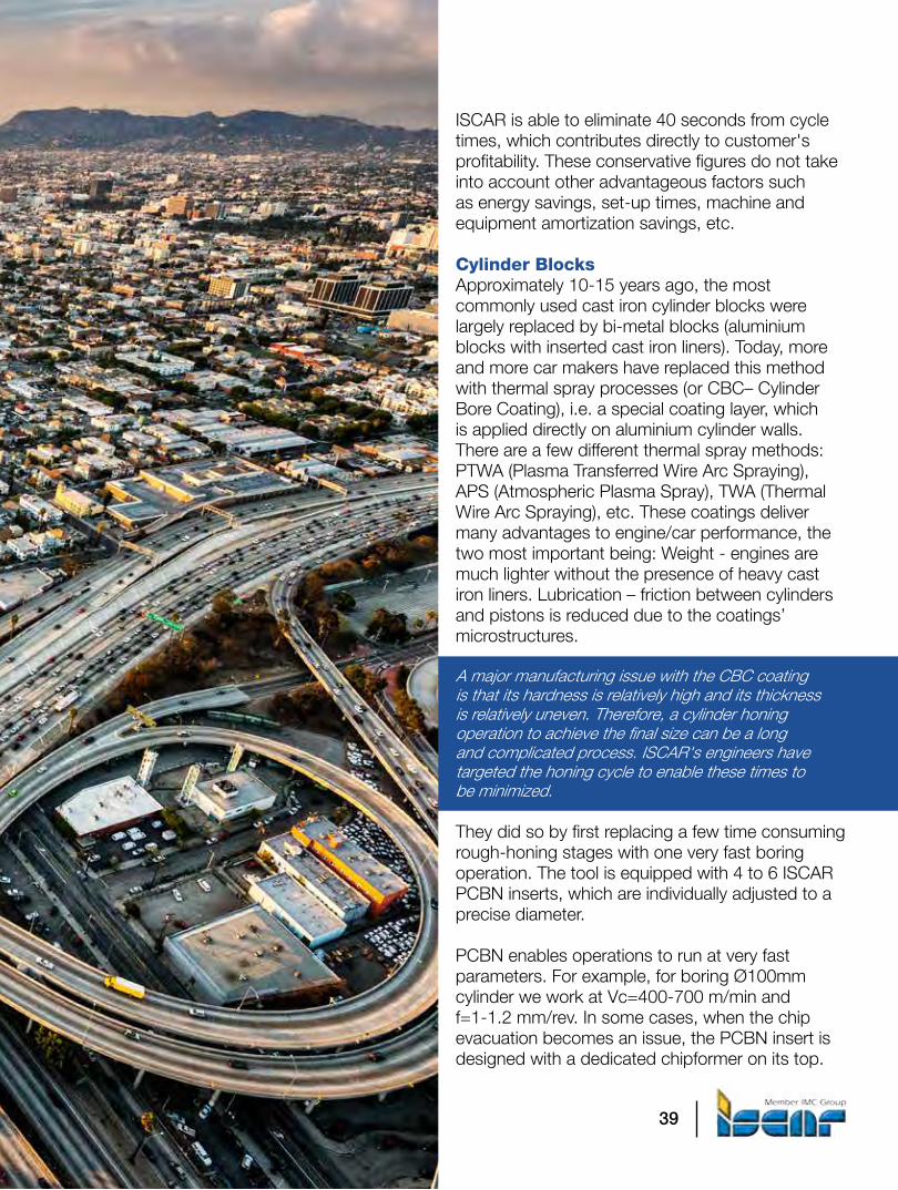
Cylinder BlocksApproximately 10-15 years ago, the most commonly used cast iron cylinder blocks were largely replaced by bi-metal blocks (aluminium blocks with inserted cast iron liners). Today, more and more car makers have replaced this method with thermal spray processes (or CBC– Cylinder Bore Coating), i.e. a special coating layer, which is applied directly on aluminium cylinder walls. There are a few different thermal spray methods: PTWA (Plasma Transferred Wire Arc Spraying), APS (Atmospheric Plasma Spray), TWA (Thermal Wire Arc Spraying), etc. These coatings deliver many advantages to engine/car performance, the two most important being: Weight - engines are much lighter without the presence of heavy cast iron liners. Lubrication – friction between cylinders and pistons is reduced due to the coatings’ microstructures.
A major manufacturing issue with the CBC coating is that its hardness is relatively high and its thickness is relatively uneven. Therefore, a cylinder honing operation to achieve the final size can be a long and complicated process. ISCAR's engineers have targeted the honing cycle to enable these times to be minimized.
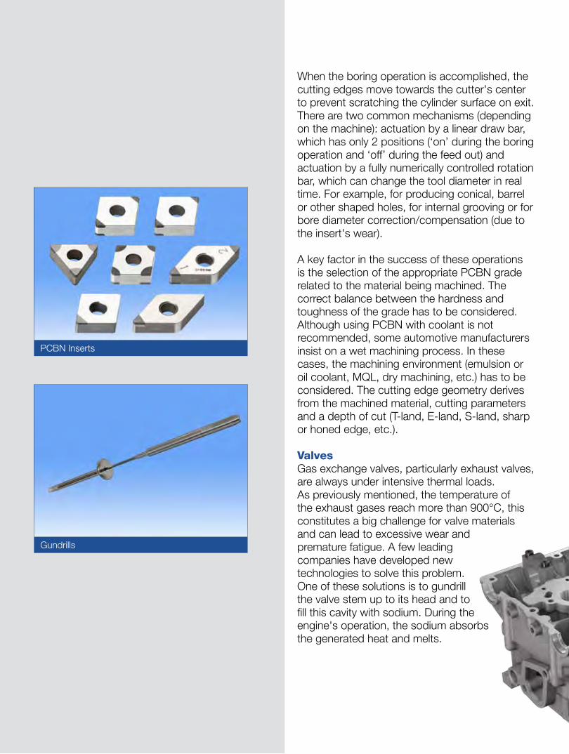
They did so by first replacing a few time consuming rough-honing stages with one very fast boring operation. The tool is equipped with 4 to 6 ISCAR PCBN inserts, which are individually adjusted to a precise diameter.
PCBN enables operations to run at very fast parameters. For example, for boring Ø100mm cylinder we work at Vc=400-700 m/min and f=1-1.2 mm/rev. In some cases, when the chip evacuation becomes an issue, the PCBN insert is designed with a dedicated chipformer on its top.
40
When the boring operation is accomplished, the cutting edges move towards the cutter's center to prevent scratching the cylinder surface on exit. There are two common mechanisms (depending on the machine): actuation by a linear draw bar, which has only 2 positions (‘on’ during the boring operation and ‘off’ during the feed out) and actuation by a fully numerically controlled rotation bar, which can change the tool diameter in real time. For example, for producing conical, barrel or other shaped holes, for internal grooving or for bore diameter correction/compensation (due to the insert's wear).
A key factor in the success of these operations is the selection of the appropriate PCBN grade related to the material being machined. The correct balance between the hardness and toughness of the grade has to be considered. Although using PCBN with coolant is not recommended, some automotive manufacturers insist on a wet machining process. In these cases, the machining environment (emulsion or oil coolant, MQL, dry machining, etc.) has to be considered. The cutting edge geometry derives from the machined material, cutting parameters and a depth of cut (T-land, E-land, S-land, sharp or honed edge, etc.).
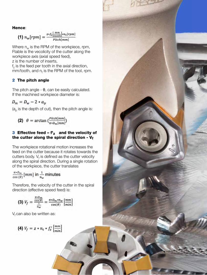
ValvesGas exchange valves, particularly exhaust valves, are always under intensive thermal loads. As previously mentioned, the temperature of the exhaust gases reach more than 900°C, this constitutes a big challenge for valve materials and can lead to excessive wear and premature fatigue. A few leading companies have developed new technologies to solve this problem. One of these solutions is to gundrill the valve stem up to its head and to fill this cavity with sodium. During the engine's operation, the sodium absorbs the generated heat and melts.
PCBN Inserts
Gundrills

41
ISCAR's solid carbide gundrills deliver outstanding surface finish, which is crucial for hollow valve applications. Diameter range: Ø0.9 – Ø16 mm (full solid carbide).
The shaking effect forces this liquid to move up and down along the stem, which dissipates the heat from the valve head to the stem and cools it. As a result, the valve head remains cooler and hence lasts much longer and the risk of valve burning, pre-ignition and loss of compression is reduced. When undertaking these manufacturing operations, in order to enable the sodium to slide easily inside the valve stem, the surface finish of the internal cavity needs to be as fine as possible. For this particular application, ISCAR suggests working with gundrills with an integral tip and body made of solid carbide with either steel or a carbide driver. These drills are designed for conventional machines, machining centers, lathes and dedicated gundrill machines. They are
• Drilling accuracy from IT7• Excellent straightness and concentricity
• Maintains high precision hole center alignment• Surface roughness of Ra 0.4 - 1.6 µm
can be easily obtained• Reboring operations are often unnecessary

42
available from Ø0.9mm and provide superior rigidity and optimal coolant flow rates.As a result of being made of solid carbide, when compared to brazed versions, these gundrills can work with up to 100% higher feeds and speed parameters. ISCAR's experts offer a very wide variety of gundrill geometrical shapes, which are designated for different drilling rates, hole accuracy and surface finish quality. The drill's shape, together with its profile must be matched to the workpiece material. In fact, this is exactly what our specialists did in this particular case. However, selecting the correct gundrill geometry is only one important step towards a successful result. A suitable cutting edge treatment (rake face polishing and edge honing to the right size) enhances the surface finish even more. It also improves the drill's performance and prolongs tool life. In addition, the gundrill body itself is being polished. It becomes very smooth and enables the chips to slide easily inside the gullet on their long evacuation.
The best results in gundrilling hollow valves have been achieved by using one of ISCAR's finest submicron carbide grades IC08 that is protected by a AlTiN nano-layer PVD coating.
CamshaftA relatively new concept for making much lighter (up to 45%) and remarkably cheaper camshafts, in comparison to the traditional method of machining from cast or forged bar stock, is assembling camshafts from modules. This system uses thermal expansion as the process principle, some OEMs fix pre-heated individual cams on to a pre-cooled precision steel tube. Others fix individual cams on to the steel tube then, by using hot air pressure to expand the tubes diameter in the places where it engages with the cams. In both cases, the lobes of each individual cam are precisely arranged in accordance with the geometry of the camshaft. The individual cams are produced either from pressed and sintered powder metal or from

43

44
hardened steels. As there are millions of these cams produced each year, manufacturers are eager to reduce machining cycle times to a minimum. As OEMs need to remain flexible, to react immediately to the frequently changing market and when possible - to spend less money - they prefer to invest in special cutting tools rather than purchase new machine tools. In order to minimize cycle time in this area, ISCAR has developed a revolutionary concept– a single innovative insert that is able to complete the entire CAM machining process. The remarkable insert is able to complete face turning, internal rough turning, internal finish turning and chamfering. The extremely durable, tangentially clamped insert faces all 4 operations, including CAM lobe profile, at the highest possible cutting parameters with equal ease and completes the CAM machining cycle within a few seconds.For deep hole drilling in forged camshafts, ISCAR offers a different approach – a deep drill with an exchangeable carbide insert.
This new idea brings many advantages to OEMs. It makes the process much more cost-effective when compared to using conventional gundrills.
The standard insert is always available in stock, it has 3 cutting edges and it negates the need for re-grinding. The insert has a positive pressed chipformer and serrated cutting edges that split chips into multiple small segments, which reduces machining torque (i.e. enables it to work with higher feeds) and improves chip evacuation. In addition, a small wiper at the end of the cutting edge provides a very fine hole surface. ISCAR's TRIDEEP drilling line (GD-DH…) holds IT10 tolerance field and covers a range of Ø16-28 mm. A standard TOGT insert has three serrated edges that create thin and short chip segments for smoother cut. These efficient, cost effective tools are highly recommended for deep drilling camshaft applications and can be used on both lathes and dedicated gundrill machines. The GD-DH drills are available at 10, 15 and 25 drilling lengths to diameter ratios. As tailored
TRIDEEP Drill
Special SUMOCHAM Step Drill

45
‘specials’, ISCAR is able to produce up to 2400 mm long TRI-DEEP drills.
PistonsMuch shorter and thin walled (sometimes friction welded) steel pistons are lighter than the conventional examples and are able to withstand much higher loads than those made from aluminum. T-piston geometry becomes more complicated and requires new and creative engineering ideas for machining difficult to access surfaces.A special tool for machining four piston ring grooves in one plunging operation. Bottom photo: ISCAR's profiling tool with precise and easily replaceable GRIP type insert machines, hardly accessible and a complicated combustion bowl on the upper part of a piston.ISCAR's goal in machining steel pistons is to reduce the number of tools needed in order to shorten cycle times. This requires a high level of creativity due to the fact that the machined areas are relatively hard to access.
Although the tool has to be thin enough to penetrate into the piston without collision, it has to be strong enough to withstand high cutting

46
forces. ISCAR's GRIP line products provide the required rigidity and versatility. The user-friendly insert clamping concept that doesn’t have removable parts, generates very high gripping forces that secure the insert in the tool pocket even when cutting directions are being changed, i.e. the tool is able to perform face grooving, right- and left side turning and profiling operations (without vibrations) and to leave a smooth and shiny surface. Also, to efficiently evacuate chips from the complicated cavities, ISCAR provides a wide variety of chipbreaking geometries that split chips into small segments and enables quick chip removal.
As a short tool life means a high number of machine stops, i.e. – inefficient machining, ISCAR has proven that the use of its Jet HP concept, which brings a high pressure coolant jet right to the cutting zone, has delivered much improved life per cutting edge. In addition, the Jet HP coolant method contributes to an efficient chipbreaking process. Automotive manufacturers’ timeframes for launching new platforms and models become shorter every year, therefore OEMs continuously pressurize Tier 2 and 3 suppliers with demands for ever shorter delivery times. Although the majority of ISCAR's automotive projects are designed at its headquarters, the company’s logistics coordinator pays special attention to the requested lead times. ISCAR has production facilities all over the world, and in many cases, for the manufacturing of special tools in the shortest possible time, ISCAR chooses a facility that is closest to the customer's location.
In addition to the time and logistics aspects, this concept brings many economical

47
advantages (less tax, lower shipment costs, etc.). ISCAR's skilled and experienced specialists provide outstanding support and service all over the world. Our teams accompany customer production processes until the final run-off completion and full project acceptance.
The environmental restrictions for much cleaner manufacturing play an important role in today's market.ISCAR’s contribution to building a better world today and in the future includes offering an efficient carbide recycling program, longer lasting tools, products with reduced power consumption characteristics and the supply of MQL compatible tools.
47
Crankshaft Flange Machining

48
Turnmilling, a process where a milling cutter machines a rotating workpiece, combines milling and turning techniques and has many advantages. Multitasking machine tools make this beneficial method more and more popular and offer an inviting prospect for the manufacturer.Machining of non-continuous surfaces or eccentric areas of rotary bodies, machiningrotating heavy-weight parts or materials that generate long chips - here turnmilling can significantly improve performance and solve various production problems. A practical question that rises while dealing with turnmilling is: how to calculate cutting data during this process?
1 The relation between tool rotation, workpiece rotation and the pitch
In turnmilling, the tool follows a spiral path (like in turning) with a predefined pitch. The pitch is practically the width of cut (ae) of the cutter and for high performance the recommended values for ae are (0.7…0.8)·Dt. The pitch should not exceed the cutters diameter, this will result in a spiral protrusion along the workpiece.
During a single rotation of the workpiece, the tool translates a pitch distance along the workpiece axis with an F table velocity.
The time that is required for the workpiece to make a single rotation is t= [min]Recall also that,Pitch=Ftable*t and Ftable=z*fz*nt.
1nw
Turnmilling Kinematics
Turnmilling A Scheme of Turnmilling Movements
49
Hence:
Where nw is the RPM of the workpiece, rpm,Ftable is the vecolicity of the cutter along the workpiece axis (axial speed feed),z is the number of inserts,fz is the feed per tooth in the axial direction, mm/tooth, and nt is the RPM of the tool, rpm.
2 The pitch angle
The pitch angle - θ, can be easily calculated. If the machined workpiece diameter is:
(ap is the depth of cut), then the pitch angle is:
3 Effective feed – f'z and the velocity of the cutter along the spiral direction - Vf
The workpiece rotational motion increases the feed on the cutter because it rotates towards the cutters body. Vf is defined as the cutter velocity along the spiral direction. During a single rotation of the workpiece, the cutter translates
Therefore, the velocity of the cutter in the spiral direction (effective speed feed) is:
Vf can also be written as:

50
The relation between the effective feed (fz') at the spiral direction and the feed (fz) at the axial direction is:
or
4 Real width of cut – ae
Fig. 1. The Side View
Fig. 2. The Top View

51
5 Cutter positioning
To avoid a clash between the tool (or the internal edge of the insert) and the workpiece, the distance Ew between the tool axis to the workpiece axis should be where w is the width of the wiper flat of an insert.
This recommendation takes cutter positioning (fig.3) to the safe side. As can be seen in fig.1, even if or even lower (depends on the workpiece diameter and the geometry of the tool), no clash will occur. A case, at which the cutter body is cleared with respect to the workpiece, and the inserts have an internal cutting edge (like for ramping operations), allows machining with Ew=0.
Fig. 3. Cutter Positioning

52
6 Material removal rateThe material removal rate (Q) in can be calculated by:
Example
A hollow steel rotary workpiece of diameter D=250 mm is roughly machined by turnmilling technique with the use of indexable milling cutter SOF 8/16-D050-04-22R carrying inserts ONMU050505-TN-MM IC830.The workpiece material is low-alloy steel AISI 4340 (~DIN W. Nr. 1.6582, ~JIS SNCM 447), HB 260…280.
The machining stock is 3 mm.
A planner needs to find cutting data, numerical values for CNC programming and metal removal rates for this operation.
Cutter data
Nominal diameter D=50 mmNo. of teeth Z=4
Initial cutting conditions
The planner decided to remove all stock by one pass and, for ensuring optimal cutting, to perform milling with width of cut 70% of D.So, depth of cut ap=3 mm and pitch=35 mm.
Based on ISCAR recommendations, the planner set cutting speed Vc=170 m/min (tool rotational velocity nt=1082.3 rpm accordingly) and feed per tooth at the spiral direction fz’=0.2 mm/tooth.
Calculations:
1 Machined workpiece diameter
2 The pitch angle
3 The feed at the axial direction
4 RPM of the workpiece
5 Velocity of the cutter at the spiral direction
6 Width of cut
7 Material removal rate

53
Turnmilling Calculator
Turnmilling, a process whereby a milling cutter machines a rotating workpiece, combines milling and turning techniques and has many advantages. Multitasking machine tools make this beneficial method more and more popular and offer inviting prospect for the manufacturer. Machining of non-continuous surfaces or eccentric areas of rotary bodies, machining rotating heavy-weight parts or materials that generate long chips – here turnmilling can significantly improve performance and solve various production problems.
The practical question is: how to calculate the cutting data during turnmilling? ISCAR proposes a way of correctly defining the data.
To summarize:
• Cutter positioning relative to the workpiece body should be done with precaution. If appropriate inserts are used, and the cutter body is far from the workpiece, no eccentricity is required; and the cutter can be positioned with Ew=0. When uncertainty appears, it is recommended to be on the safe side and use
• If the feed is given at the workpiece axis direction (fz), then the workpiece rotational velocity can be calculated by:
• If the feed is given at the spiral direction (f'z), then the workpiece rotational velocity can be calculated by:

54
Every year ISCAR holds a dozen customer seminars at the company's headquarters in Tefen. During several days, seminar attendees attend a series of informative lectures and presentations, witness practical demonstrations of cutting tools at work in the Technical Center and visit production facilities. ISCAR strongly believes that participating in the seminars is a very effective means, not only to improve customers’ knowledge related to cutting tools and to receive comprehensive updates regarding new products, but also to gain knowledge of ISCAR’s advanced manufacturing, quality control and the company’s staff. These seminars provide an opportunity to learn a little about ISCAR’s history and to become acquainted with the culture and philosophy of the company. Indeed, as gaining an understanding of the role of ISCAR cutting tools is the most important issue, who better to explain these important topics than Jacob Harpaz, the CEO of ISCAR and president of the IMC Group. Attending the renowned ISCAR seminars provides a chance to receive first-hand answers related to a range of fundamental topics, such as the impact of the cutting tool on machining productivity and profitability, what is the tool IQ and what does SUMOTEC post-coating treatment contribute to carbide grades. The open atmosphere during the presentations also provides a good opportunity to put a question to Jacob Harpaz, and to hold a short discussion.
International customer seminars are conducted regularly at ISCAR Tefen Headquarters
ISCAR invests highly in customer seminars around the globe. Thousands of customers partake in this exciting event where they learn from IMC president and ISCAR CEO, Jacob Harpaz.
The Power of Seminars

55
By witnessing practical demonstrations of the cutting tools at work in the Technical Center, attendees are able to analyse the cutting data and the process parameters. Also, if desired even "touch" the generated chips and discuss the performance of the tools with the machine tool operator. The demonstrations help to illustrate and confirm the material covered in the presentation and to enable a personal opinion to be formed regarding tool advantages. Visiting ISCAR production facilities provides a close contact opportunity
to become familiar with the company’s technology, plant and personnel. Without doubt, seeing once is better than hearing twice. We believe that the seminars, organized as above, are informative, interesting, and very beneficial to all attendees. They represent an important link in a whole ISCAR service and support chain that is designed to create a productive partnership with our customers. The extremely positive feedback we receive confirms that attendees appreciate our approach.

56
Industrial vending machines have been providing an efficient means of storing and issuing consumable tooling for more than 20 years. Whilst the US was the first country to seriously adopt such convenient systems, over the past 2 decades their use has become widespread throughout global industry. Today there are 10’s of thousands of units in service. The use of these systems continues to grow as potential users realize the multiple benefits that they deliver. Also, as multi-national companies diversify their geographic manufacturing bases, a host of best practices, including the efficient dispensing of cutting tools to the shop floor, tend to migrate across borders.
Industrial vending machines bring major mutual benefits to both the cutting tool provider, in particular the distributor or integrator, and the end-user.
Sellers are eager to provide their customers with easy and reliable access to their products as a guarantee of repeat business, and are keen to exploit potential growth opportunities. A vending machine strategically located on a shop floor helps to stabilize the business relationship between the customer and vendor and help to ensure that business is not lost to competitors who deliver cutting tools in a traditionally less convenient way. Whereas, purchasers are seeking to guarantee the instant availability of tools to ensure that their production does not stop. In addition, they see the implementation of an industrial vending machine system as a way to minimize the cost and risk of ownership of stock, by optimizing stock levels or entrusting the ownership of stock with their supplier through consignment arrangements. In the last few years, there has been an exponential growth in vending businesses, with many of the major players investing heavily in new equipment installations.
Advanced Vending Systems forHigher Productivity
57
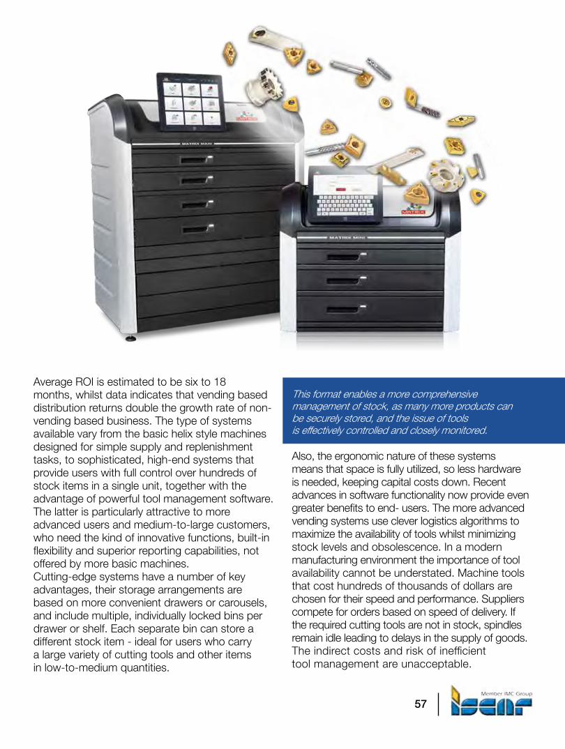
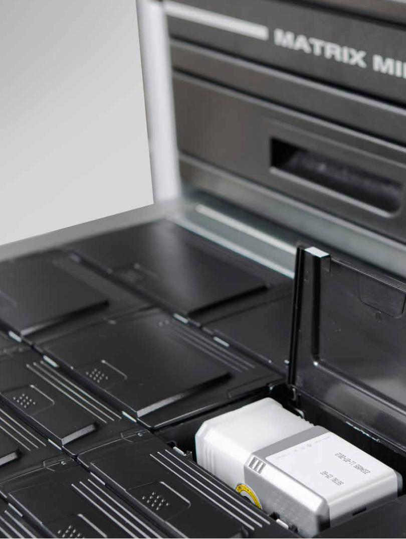
Average ROI is estimated to be six to 18 months, whilst data indicates that vending based distribution returns double the growth rate of non-vending based business. The type of systems available vary from the basic helix style machines designed for simple supply and replenishment tasks, to sophisticated, high-end systems that provide users with full control over hundreds of stock items in a single unit, together with the advantage of powerful tool management software. The latter is particularly attractive to more advanced users and medium-to-large customers, who need the kind of innovative functions, built-in flexibility and superior reporting capabilities, not offered by more basic machines.Cutting-edge systems have a number of key advantages, their storage arrangements are based on more convenient drawers or carousels, and include multiple, individually locked bins per drawer or shelf. Each separate bin can store a different stock item - ideal for users who carry a large variety of cutting tools and other items in low-to-medium quantities.
This format enables a more comprehensive management of stock, as many more products can be securely stored, and the issue of tools is effectively controlled and closely monitored.
Also, the ergonomic nature of these systems means that space is fully utilized, so less hardware is needed, keeping capital costs down. Recent advances in software functionality now provide even greater benefits to end- users. The more advanced vending systems use clever logistics algorithms to maximize the availability of tools whilst minimizing stock levels and obsolescence. In a modern manufacturing environment the importance of tool availability cannot be understated. Machine tools that cost hundreds of thousands of dollars are chosen for their speed and performance. Suppliers compete for orders based on speed of delivery. If the required cutting tools are not in stock, spindles remain idle leading to delays in the supply of goods. The indirect costs and risk of inefficient tool management are unacceptable.

58
Although predictability is a key factor in ensuring availability, the most recent software packages offer clever user-defined features that allow users to customize stock levels for items that are used infrequently. This can be achieved by overriding the calculated minimum stock level, or inputting changes in relevant parameters such as frequency, usage and lead time, automatically generating changes to the calculated minimum stock level. Changes can be achieved on the spot, rather than waiting for a weekly or month end process, so that the system is always up to date.
There have also been significant advances in a range of other areas that make these new generation systems extremely intelligent. It is of vital importance that only the right tools are used for a job. The Bill of Materials normally defines the required cutting tools, however to be sure that only these tools are actually used, a limitation can be defined in the software, so that at the time of issue, the user inputs the part number, after which only the tools in the Bill of Materials can be issued for use.
59

60
In today’s digital world, there are many ways to connect with customers. At ISCAR, we analyze whether the enormous investment associated with trade shows is still worth the effort. In some countries trade show attendance has dropped making them less significant. Yet the leading industry trade shows, those which can be considered as Olympiads, continue to show increased numbers of attendees. It is difficult to measure the ROI, yet the great turnout at the last IMTS, AMB and JIMTOF are proof that meeting people face to face offers much more than just a digital imprint. ISCAR booths continue to be one of the main cores, centers of attraction where a smile and a warm greeting promise the building of new or existing customer relationships. It’s where business happens. Aside from exhibiting tool
displays, ISCAR’s personnel manning the booths measure their attendees by acquiring track leads, conducting surveys, connecting with distributors and maintaining existing business relationships. The lounge area is where gatherings often prove to be a valuable meeting place to discuss and reacquaint with existing customers. So, to again answer the question of whether or not trade shows are worth it, yes! Especially now in the digital age where we need to blend different forms of marketing media to reach customers.
Are Trade Shows Worth It In the Digital Age?

61
AMB is one of the top 5 trade fairs worldwideGermany’s AMB is the leading industry trade fair and one of the top 5 trade fairs worldwide for metal cutting technology. In 2016, more than 1,450 exhibitors from 33 countries showcased their latest developments for machining metal. Nearly 90,000 visitors attended the show at the high tech grounds of Messe Stuttgart. ISCAR’s unique double decker booth provided an outstanding architectural structure to host the many visitors which came to see the live Chameleon body painting event.
4% compared to 2014
90,000visitors
AMB Exhibition

62
IMTS showed the highest number of exhibitors in historyAmerica’s largest manufacturing show, the International Manufacturing Technology Show, is one of the largest industrial trade shows in the world. In 2016, this show hosted the highest number of exhibiting companies ever, totaling 2,407 exhibitors. A total of 115,612 registrants visited the show, the third highest total ever and the record for a six day show.
115,612visitors
5% compared to 2014
IMTS Exhibition

63
JIMTOF - 28th Japan International Machine Tool FairThe number of visitors at JIMTOF 2016 steadily increased with nearly 147,602 visitors from over 80 countries. As JIMTOF is primarily an Eastern Asian trade show, it is interesting to note that the number of visitors from overseas countries exceeded 10,000 people. ISCAR’s booth was the center of attraction among the many Japanese carbide tool manufacturers. This phenomenon is not obvious, as competing for a dominant position among the Japanese companies is very challenging.
147,602visitors
8% compared to 2014
JIMTOF Exhibition
64
G 1
/201
7 ©
ISC
AR
LTD
All
right
s re
serv
ed 3
3329
37