The Behaviour of Curved Hybrid Girders
140
University of Cape Town THE BEHAVIOUR OF CURVED HYBRID GIRDERS A thesis submitted in partial fulfilment of the requirements for the degree of MASTER OF SCIENCE of UNIVERSITY OF CAPE TOWN ' Author: Kabani Matongo Supervisor: Dr A. Masarira December 2008 The financial assistance of the Department of Labour (DST) towards this research is hereby acknowledged. Opinions expressed and conclusions arrived at, are those of the author and are not necessarily to be attributed to the DST.
Transcript of The Behaviour of Curved Hybrid Girders

Univers
ity of
Cap
e Tow
n
THE BEHAVIOUR OF CURVED HYBRID GIRDERS
A thesis submitted in partial fulfilment of
the requirements for the degree of
MASTER OF SCIENCE
of
UNIVERSITY OF CAPE TOWN
'
Author: Kabani Matongo
Supervisor: Dr A. Masarira
December 2008
The financial assistance of the Department of Labour (DST) towards this research is hereby acknowledged. Opinions expressed and conclusions arrived at, are those of the author and are not necessarily to be attributed to the DST.

The copyright of this thesis vests in the author. No quotation from it or information derived from it is to be published without full acknowledgement of the source. The thesis is to be used for private study or non-commercial research purposes only.
Published by the University of Cape Town (UCT) in terms of the non-exclusive license granted to UCT by the author.
Univers
ity of
Cap
e Tow
n

Declaration
I know the meaning of plagiarism and declare that all of the work in the document,
save for that which is properly acknowledged is my own. This dissertation has not
been submitted before for any degree or examination at any other University.
Kabani Matongo
Decemeber 2008
Signature Removed

Acknowledgements
I would like to extend my gratitude to the following:
• Dr Alvin 1\Iasarira for the research supervision,
• The NRF for the main scholarship,
• Prof Zingoni and the Civil Engineering department for the additional financial
support,
• My collegues in the structural engineering and materials group most notably
Bongani and Otieno for the encouragement and proof reading,
• Patrick Sibanda for all the latex hints and tricks,
• My family and friends: Masimba, Habeenzu, Mudenda and all the Kabanies
for their support,
• The medical teams at Spencer Rd Clinic and UCT wellness for being there all
the time for me,
• My beloved Mutinta and Nakwezi who bore the brunt of my absence

Abstract
Curved girders are used in bridges to fit predefined alignment. Hybrid girders are
an innovative use of high strength steel enabling optimising moment capacity.
Previous studies of curvature and hybrid girder effects have been disjointed,
focusing on curved homogeneous girders and straight hybrid girders. There are no
generally accepted curved girder equations and this has implications in the study
of curved hybrid girders since the hybrid effects become apparent in the inelastic
range. Furthermore, the range of radius to span ratio where available analytical
procedures can be applied is not known.
A total of 48 girders are investigated, 12 of which are straight. The girders are all
simply supported, un-braced and loaded at midspan. The load-deflection behaviour
of curved hybrid girders is investigated. Stress plots of the girders are obtained at
ultimate load. The radius to span ratio is varied from 5 to 50 for 5m span girders
and from 5 to 30 for 8m span girders. Three steel grades are used to obtain hybrid
girder configurations, with higher yield steel always used in the flanges. The web
flange yield steel combinations used are 350MPa/460MPa, 350MPa/690MPa and
460MPa/ 690MPa.
A finite element model using ADINA version 8.4 is used to investigate curved girder
behaviour. The collapse analysis option is used to trace behaviour as the load is
incremented automatically to a prescribed displacement. Available experimental
data is used to check the validity of the modeling assumptions.
The presence of curvature radically modifies a girder's load pattern by causing
additional lateral bending moments. Lateral bending moments reduce the vertical
load carrying capacity of a girder and cause the flanges to be unequally stressed.
For the girder and spans investigated, there is a reduction of 57% in ultimate load
for radius to span ratio (R/L) of 5 compared to a straight girder of similar
proportions and span. The effects of curvature reduce as R/L increases and this is
observed in the 5m homogeneous girder with R/L of 50 which attained more than

iv Abstract
91% of the straight girder load capacity. The 8m girder with R/1 of 30 attained
more than 83% of the equivalent straight load girder capacity.
The hybrid girders investigated had load-deflection curves close to corresponding
homogeneous girders with flange steel grade, reaching more than 97% of the ultimate
load capacity of reference homogeneous girders. The hybrid factors as proposed
in the simplified design procedure are adequate and can be applied to analytical
equations that predict curved homogeneous girder loads. The available analytical
equations give conservative loads for both hybrid and homogeneous girders compared
to the finite element method when R/1 is 5 and are unconservative for higher rations.
Contents
Declaration . . . . . . . . . . . . . . . . . . . . . . . . . . . . . . . . . . . . i
Acknowledgements . . . . . . . . . . . . . . . . . . . . . . . . . . . . . . . ii
Abstract . . . . . . . . . . . . . . . . . . . . . . . . . . . . . . . . . . . . . . iii
Chapter 1: Introduction and literature review
1.1 Introduction . . . . .
1.2 Literature review ..
1.3 Research motivation
1.3.1 Problem definition
1.3.2 Research aims ...
1.3.3 Scope of research .
1.3.4 Research limitations
Chapter 2: Theory .... .
2.1 Introduction ..... .
2.2 Plate Girder behaviour
2.2.1 Buckling .
2.2.2 Bending .
2.3 Hybrid girders . .
2.3.1 AASHTO LRFD Approach
2.3.2 EN3-l-1 Approach .. .
2.4 Curved girders ........ .
2.4.1 Curved girder equations
2.4.2 Preliminary design . . .
1
1
4 26
27
27
28
28
30
30
32
32
36
37
40
42
43
44 51
vi CONTENTS
2.5 Finite Element Method . . . . . . . . . . . . . . . . . . . . . . . . . . 56
Chapter 3: Methodology . . . . . . .
3.1 Introduction ...........
3.2 Computational model variables
3.2.1 Girder geometry • 0 ••
3.2.2 Girder support and load input .
3.2.3 Material modeling
3.2.4 Material Yielding
3.2.5 Elements ..
3.3 Analysis technique
3.4 Post processing ..
Chapter 4: Numerical model investigation and results
4.1 Introduction . . . . . . . . . . . .
4.2 Model definition and verification .
4.2.1 Mesh convergence .
4.2.2 Model verification .
4.3 Model studies . . . . . .
4.3.1 Curvature effects
4.3.2
4.3.3
4.3.4
Analytical determination of ultimate strength
Investigation of hybrid effects on curved girders
Analytical determination of ultimate strength .
Chapter 5: Conclusion and recommendations.
5.1 Conclusion .....
5.2 Recommendations .
58
58
59
59
61
62
66
68
69
71
72
72
73
78
79
82
83
92
97
. 108
.111
. 111
. 112
Appendices . . . . . . . . . . . . . . . . . . . . . . . . . . . . . . . . . . . . 114
Appendix A: Solution of quartic equation . . . . . . . . . . . 116
A.1 Quartic equation derived by Fukumoto and Nishida (1981) . 116
A.2 Matlab program . . . . . . . . . . . . . . . . . . . . . . . . . 116
CONTENTS
Appendix B: Solution of quartic equation ........ .
B.1 Quartic equation presented by Shanmugan et al. (2003)
B.2 Matlab program ..................... .
Appendix C: Hybrid factor AASHTO {2007)
C.1 Hybrid factor . . . . . . . . . . . . . . . .
Appendix D: Girder moment capacity: SANS 10162-1
D .1 Yield moment . . . . . . . . . . . . . . . . . . . . . .
vii
.118
. 118
. 118
.120
. 120
.122
. 122
References . . . . . . . . . . . . . . . . . . . . . . . . . . . . . . . . . . . . . 124

List of Figures
1.1 Single web and multiweb girder cross-section . . . . . . . . . . . 2
1.2 HPS Bridges in service in U.S (Gunther, 2005) . . . . . . . . . . 6
1.3 Moment-rotation curve illustration moment ductility parameters 8
1.4 Experimental bending behaviour curves for hybrid beams (ASCE-
AASHO, 1968) . . . . . . . . . . . . . . . . . . . . . . . . . 9
1.5 Comparison of Fukumoto and Nishida (1981) and Shanmugan et al.
(2003) equations . . . . . . . . . . . . . . . . . . . . . . 17
1.6 Possible buckling modes of !-Girder sectionSalmon and Johnson (1996) 20
2.1 Girder stress . . ....... .
2.2 Moment deflection for hybrid girder
2.3 Hybrid girder stress distribution . .
2.4 Warping and vertical bending stresses .
2.5 Forces on a curved girder element (Heins, 1975)
2.6 Equilibrium of forces on curved girder element (Heins, 1975)
3.1 Flow chart for computational investigation
3.2 350W Domex steel stress-strain plot .
3.3 460W Domex steel stress-strain curve .
3.4 690MC Domex steel stress-strain curve
3.5 Residual stress pattern on !-section . .
3.6 Misses yield criterion locus for biaxial stress state
3. 7 Four-node quadrilateral . . . . . .
3. 8 Load deflection sketch showing critical load .
4.1 Curved beams . . . . . . . . . . . .
4.2 Material model for AR and BR curved beams
4.3 Load-deflection curves for different mesh densities
4.4 Load-deflection curves for AR curved beams . .
37
38
39
44
45
47
60
64
65
65
66
68
69
70
76
77
79
80

LIST OF FIGURES ix
4.5 Load-deflection curves for BR curved beams . . . . . . . 80
4.6 Load-deflection curves for CB curved beams . . . . . . . 82
4.7 Load-deflection curves for LU5-R25 homogeneous girders 84
4.8 Load-deflection curves for LU5-R100 homogeneous girders 84
4.9 Load-deflection curves for LU5-R250 homogeneous girders 85
4.10 Load-deflection curves for LU8-R40 Homogeneous girders . 86
4.11 Load-deflection curves for LU8-R120 Homogeneous girders 86
4.12 Load-deflection curves for LU8-R240 Homogeneous girders 87
4.13 Comparison of load-deflection curves for LU8 at various curvatures 88
4.14 Comparison of load-deflection curves for LU5 at various curvatures 88
4.15 Stress plot for LU5-R25aa girder. . . . . . 89
4.16 LU5-R25aa girder flange lateral movement 89
4.17 Stress plot for L U 5-R25aa girder flange . . 90
4.18 Stress plot for LU5-R100aa girder . . . . . 90
4.19 LU5-R100aa-Compression flange lateral movement: 91
4.20 Stress plot for LU5-R100aa girder flange . . . . . 91
4.21 LU5-R25aa: Graphical solution for ultimate load. 94
4.22 Stress plot for LU5-R25ab girder . . . 98
4.23 Stress plot for LU5-R25ac girder . . . . . . . . . . 98
4.24 Stress plot for LU5-R25ac girder flange . . . . . . 99
4.25 Mesh plot of LU5-R25ab girder showing local buckling 99
4.26 Load-deflection plot comparison for LU5-R25ab . . . . . 101
4.27 Load-deflection plot comparison for LU5-R25ab and LU5-R25ac . 101
4.28 Load-deflection plot comparison for LU5-R100ab . . . . . . . . . . 103
4.29 Load-deflection plot comparison for LU5-R100ac and LU5-R100bc . 103
4.30 Load-deflection plot comparison for LU5-R250ab . . . . . . . . . . . 104
4.31 Load-deflection plot comparison for LU5-R250ac and LU5-R250bc . 104
4.32 Load-deflection plot comparison for LU8-R40ab . . . . . . . . . . 105
4.33 Load-deflection plot comparison for LU8-R40ac and LU8-R40bc . . 105
4.34 Load-deflection plot comparison for LU8-R120ab . . . . . . . . . . . 106
4.35 Load-deflection plot comparison for LU8-R120ac and LU8-R120bc . 106
4.36 Load-deflection plot comparison for LU8-R240ab . . . . . . . . . . . 107
4.37 Load-deflection plot comparison for LU8-R240ac and LU8-R240bc . 107
List of Tables
1.1 Cost comparison of steel grades (Gunther, 2005)
2.1 SANS10162 Section classification
2.2 EN3-1-1 Section classification
3.1 Girder geometry data
4.1 Dimensions and curvatures of curved beam
6
36
36
61
73
4.2 Dimensions and curvatures of laterally supported curved beams 75
4.3 Comparison of Experimental and FEM results-laterally unsupported . 81
4.4 Comparison of Experimental and FEM results for CB beams . . 81
4.5 Curved girder geometry data . . . . . . . . . . . . . . 83
4.6 Comparison of analytical and finite element ultimate loads for
homogeneous girders . . . . . . . . . . . . . . . . . . . . 95
4. 7 Analytical and finite element ultimate loads for straight homogeneous
girders . . . . . . . . . . . . . . . . . . . . . . . . . . . . . . . . . . . 96
4.8 Comparison of normalised ultimate loads for different curvatures . . . 96
4.9 Comparison of analytical and finite element ultimate loads for hybrid
girders . . . . . . . . . . . . . . . . . . . . . . . . . . . . . . 109
4.10 Comparison of normalised ultimate loads for hybrid girders . 110

Chapter 1
Introduction and literature review
1.1 Introduction
Plate girders have been used in bridges to replace trusses in order to achieve long
spans. With considerable improvement in the practice of welding, plate girders are
now welded as opposed to riveting and bolting. Plate girders differ from beams
in that web buckling is more critical as opposed to web yielding. Several types of
girders are utilised and are grouped as single web such as I girders or multi-web
girders such as box girders. Alternatively the girders can be classified according to
the material variations in the web and flange area. Thus homogeneous girders have
the same material in both web and flange areas while hybrid girders have different
steel grades in flanges and web. The word hybrid is thus used to denote girders with
different steel grades while composite is used to refer to concrete-steel girders.
This study looks at horizontally curved hybrid girders with doubly symmetric
cross section, here after simply referred to as hybrid curved girders. The horizontal
curvature arises in highway bridge applications to fit predefined alignments for
bridges, increase sight distance for drivers as well as allow high speed traffic to
change direction (Hall, 1996).
Despite the increasing use of curved girders in bridges, their behaviour under
different load conditions during and after construction and the reliability of
analysis tools is still not fully understood (NCHRP-Report-563, 2006). Analytical
studies on curved beams have been carried out by Timoshenko (1961); Vlasov
(1961) and their formulations have been the starting point for many researchers.
The curvature results in lateral moments in addition to the vertical moment
experienced by straight girders.

2 CHAPTER 1. INTRODUCTION AND LITERATURE REVIEW
1- girder Box girder
Figure 1.1: Single web and multiweb girder cross-section
Research on curved beams initially followed a rigorous theory of elasticity approach.
Exact solutions have been formulated for solid sections as reported by Ugural and
Fenster (1981). The most important departure from curved straight beams is the
presence of radial stresses. The theory developed led to the following conclusions:
(i) if the depth of member is smaller relative to the radius of curvature then the
initial curvature may be neglected.
(ii) the strain energy due to bending for a straight beam is a good approximation
for the curved slender beams.
Other simplifications by Winkler resulted in formulae that are easier to use for
rectangular sections. However, the formulae are not accurate for thin walled I
sections because of the distortional effects of the stress variations in flanges and
web. Tables of correction factors are used for the computation of stresses and
strains for different loading cases of curved solid beams and hollow sections that
do not fall in the class of thin walled sections. Modification factors have been
proposed to correct the error occurring for thin walled beams.
Background research on plate girders was carried out by Basler(1961) whose study
covered the aspects of shear, bending and combined shear and bending. Subsequent
research on curved girders and hybrid girders was carried out rather disjointly.
Some of the early work in the area of curved girders was done under the
Consortium University Research Team (CURT) project which developed analytical
models and performed field tests. The results from the CURT project were
included in the AASHTO Guide Specification that was published in 1976. The
Guide Specifications that were developed in the US were disjointed and difficult to
1.1. INTRODUCTION 3
follow (Hall, 1996). There are discontinuities between compressive strength
formulations between compact and non compact sections and as the radius of
curvature was increased to infinity, there is no convergence to the straight girder
equations (Davidson et al., 2000b). Other researchers such as Dabrowski presented
equations for non uniform torsion of curved girders with non deformable
asymmetrical cross section (Richard et al., 1995). Approximate methods were
developed including the V-load analysis for shears and moments. Corresponding
work was done by the Hanshin Expressway Corporation where an interaction
equation for limiting stresses in curved girders was proposed, culminating in the
Hanshin Guide (Davidson et al., 2000b; Hall, 1996)
Most of the research conducted especially in the US by CURT was on doubly
symmetric I girders. The approach which will be reviewed in subsequent sections
was for making adjustments to straight girder equations to predict curved girder
behaviour. This approach has led to limited success in predicting curved girder
behaviour and there is still no comprehensive theory explaining inelastic curved
girder behaviour (Hall, 1996). More recent studies have addressed the behaviour of
curved girders using Finite Element Models (Shanmugan et al., 2003, 1995)
Hybrid steel girders have also been used in bridges (Veljkovic and Johansson, 2004;
Haaijer, 1961). They result in savings in dead weight due to the optimisation of
moment resistance properties. Hybrid girders are fabricated by welding different
steel grades in the flanges and the web. In the elastic range the hybrid girder
behaves just like a homogenous girders. However when the steel in the web yields,
there is a slight reduction in stiffness. The flanges provide most of the moment
carrying capacity and it is the yielding of steel in the flanges that reduce girder
stiffness. Failure for straight hybrid girders is defined as the initial yielding of steel
in the extreme flange fibres.
Some research on hybrid girders was done in in the 1960s most notably by Frost and
Schilling (1964). These studies covered both experimental and theoretical aspects of
hybrid girder design and formed the basis of the design procedures recommended by
the ASCE-AASHO subcommittee on hybrid beams and girders. The deformation
and stress patten where examined and stability issues were not examined as local
and lateral buckling were excluded by careful proportioning of member sizes. A
report by the subcommittee on hybrid beams and girders (ASCE-AASHO, 1968)
noted that just like in homogeneous beams and girders, shear is significant in the
web. While the web contributes little in bending resistance, web yielding may affect

4 CHAPTER 1. INTRODUCTION AND LITERATURE REVIEW
the buckling of the compression flange of the girder. For hybrid girders, tension
field action was ignored. Recent research has recommended a relaxation of this
conservative assumption.
Hybrid girders can thus be designed in the same manner as homogeneous girders
when their response is in the linear-elastic range. However, this does not fully utilise
the full capacity of the higher grade steel in the flanges. The use of high strength
steel in the flanges results in the web yielding first while the flanges remain elastic
as the load is increased. Shear is normally carried by the web and thus there should
be no significant difference with corresponding behaviour of homogenous girders.
The effects of curvature and hybrid nature of the beams is thus presented in detail
below.
1.2 Literature review
The study of hybrid girders closely follows the developments made in steel
production science. As stated, hybrid girders make use of different grades of steel,
the low strength steel in the web and a higher strength steel in the flanges. The
placement of high strength steel in the flanges is because they are the primary
moment resisting members. As high strength steel is often more expensive, the
hybrid configuration provides an optimum solution by placing high strength steel
where it is needed most. The web helps carry shear and also keep the distance
between the flanges. A review of the use of steel and and types of steel is necessary
if they are to be efficiently used in girders. The review is important also due to the
limitations that design codes place on issues such as inelastic design and
definitions of sections that can attain plastic moment capacity.
Advances in material science and analysis techniques have allowed innovative
structural designs from the time iron became an affordable construction material.
Different materials such as cast iron, wrought iron and steel have all been used in
construction over the past 200 years. The main difference in chemical composition
of these materials is the percentage of carbon in the iron. In steel the carbon is
less than 2%. There are typically four groups of steel used for structural purposes
with progressive increase in strength; carbon steels, high-strength low alloy (
HSLA) steels, heat treated carbon and HSLA steels and heat-treated alloy steels.
For classification of steel, regulatory bodies identify 'minimum' yield strength,
chemical composition and heat treatment. Yield stressed are in the range
..
1.2. LITERATURE REVIEW 5
205-290MPa for carbon steels, 290-450MPa for HSLA steels, 315-515MPa for heat
treated carbon and HSLA steels and 620-690MPa for heat treated alloy steels
(Paik and Thayamballi, 2003). The ultimate tensile yield stresses are the in range
380-620MPa for carbon steels, 415-550MPa for HSLA steels, 450-790MPa for heat
treated and HSLA steels and 760-895MPa for heat treated alloy steels (Paik and
Thayamballi, 2003).
There are significant differences in the stress-strain curves for the different steels.
Generally, mild steels exhibit a linear response up to the yield stress. This is followed
by a yield plateau where strain increases at an almost constant load, after which
strain hardening takes place. An example of such a steel is the A36 steel. The ability
to undergo large strains after attaining yield stress is the basis for plastic design.
In general, high strength steels tend not to have this yield plateau thus exhibiting
poor ductility. This is the main reason for the LRFD not permitting plastic design
or inelastic analysis for such steels (Salmon and Johnson, 1996).
Steel with tensile strength of 600MPa was used in bridge construction in the 1960s
in Japan. Steel with strength 800MPa was used in mid 1960s in bridges such as
Hanawa Overpass Bridge and Minato Ohashi Bridge. In the US, HSLA structural
steels were developed in the 1960s and A514 steel was introduced (Bjorhivde, 2004).
This A514 steel did not have sufficient ductility resulting in brittle fracture of tension
flange of test specimen. 800MPa yield strength steels with better weldability were
introduced in 1992 in Japan and a new grade A992 structural steel was introduced in
the US in 1998. This A992 steel has better weldability, ductility and has a minimum
yield strength of 350MPa.
High strength steels suffer from poor weldability and ductility though this is fast
changing due to advances in steel production techniques. There has been a
significant growth in the use of high strength steel particularly with the emergence
of a class of steel referred to as High Performance Steel (HPS). This is partly due
to technological innovations in steel production such as the Thermo-Mechanical
Control Process (TMCP) that controls rolling and cooling process producing steel
with fine microstructure (Gunther, 2005). These steels have superior properties
such as higher ductility, weldability, fracture toughness and better weathering
properties apart from the high strength. In the US, the development of bridge
HPS only started in 1992. The Figure 1.2 shows the number of bridges constructed
in the US using HPS up to 2004. There has been an increase in the use of HPS
over the period shown.
t ' ~ f ~'
I ! r !
I I i f i
I f l t ! I I I I I I I I
I I

6 CHAPTER 1. INTRODUCTION AND LITERATURE REVIEW
Growth in Total Number Opened to 5ervice 154 est.
140 120 100
BO 60 .uJ 20 0
1997 1998 1999 2000 2001 2001 2003 2004
Figure 1.2: HPS Bridges in service in U.S (Gunther, 2005)
The general costs involved in using HPS can vary depending on complexity of
structure and location. The cost of materials can often be a small component of
the structure. Table 1.1 shows cost comparison based on experience in the US.
Other costs include erection and fabrication costs. The comparison is on unit cost
of material, fabricated members and in-place cost. TMCP technology has resulted
in a slight cost reduction as reflected by Table 1.1 for HPS70W and HPS70 TMCP.
Table 1.1: Cost comparison of steel grades (Gunther, 2005)
Material Fabricated In-Place ($ per kg) ($per kg) ($per kg)
Grade 50W 0.77-0.93 1.21-1.37 2.20-2.76 HPS 50W 0.93-1.10 1.39-1.57 2.54-3.09 HPS 70W 1.06-1.32 1.65-1.83 2.60-3.31 HPS 70W TMCP 0.99-1.27 1.54-1.72 2.54-3.20
The areas regarding use of HPS in bridges that were highlighted for research
included deflection criteria, ductility, flexural capacity in negative regions,
limitation on tension field action in hybrid girders, toughness, fatigue and fracture
(Azizinamini et al., 2004). The advantages of using HPS have been well
documented (Gunther, 2005; Miki et al., 2002). High yield strength means that
fewer girders can be used to carry load and longer spans can be obtained for
bridge applications. Alternatively, shallower girders can be used where clearance
height is of concern. Good weathering properties mean the steel can be exposed to
f • l ~ ,, ~ • I

1.2. LITERATURE REVIEW 7
the atmosphere without having to paint it, thus reducing life-cycle costs. However,
there are restrictions placed by design codes on the use of high strength steel,
particularly on the definition of compact sections (Wollman, 2004). These
restrictions limit the full utilisation of HPS strength. Inelastic analysis and
moment redistribution are not allowed for steels with a yield strength greater than
490 MPa. Such limits are based on the general reduced ductility that was observed
in high strength :>teels whose stress-strain curve generally has no well defined yield
plateau. The South African code SANS10162:1-2005 does allow the use of steel
within the following limitations:
(i) the specified yield stress shall not exceed 700MPa.
(ii) ratio of the minimum tensile strength to specified yield stress shall be at least
1.2:1.
(iii) the elongation ( on a gauge length of 5.56 JAo mm ) shall be at least 15%,
where A0 is the original area of the cross section in square millimetres
A compact section with adequate bracing is expected to develop full plastic moment
and meet the ductility criteria to allow for both plastic design and inelastic moment
redistribution. However, previous AASHT0(1998, 2002) have restrictions placed on
the definition of a compact section by giving a limit on steel yield strength. Thus
the requirement for a section to be compact is among others that the steel used
should have a yield stress less than 490MPa (Wollman, 2004). It is evident that the
full benefits for HPS can be realised if design codes allow plastic design as well as
inelastic analysis. This has greater implications for hybrid girders as they rely on
the optimum use of high strength steel in regions of high moments. The limitations
have been the subject of study. The studies mainly followed the pattern where
girders both homogeneous and hybrid are designed while ignoring the restriction
placed on steel strength. The objective of these studies was to check if such girders
could have enough flexural ductility in terms of rotational capacity to allow plastic
moment capacity to be attained.
Sufficient ductility is necessary for a section to develop plastic moment capacity.
Brittle fracture should not occur so that plastic hinges can develop. Examples of
steels with desirable characteristics with regard to weldability and ductility are given
in the ASCE (1971) as ASTM A36, A441 and A572. In general, such steels have
adequate plastic yield plateau and show strain hardening. This allows plastic hinge
formation and maintenance of the plastic capacity until the collapse mechanism is

8 CHAPTER 1. INTRODUCTION AND LITERATURE REVIEW
fully developed. Ductility can be defined as the amount of permanent strain before
fracture. For flexural members, ductility is measured in terms of rotational capacity
R, given below (ASCE, 1971) and the other variables in the definition are shown in
Figure 1.3:
(1.1)
where Bu is the rotation when moment capacity drops below Mp during unloading
and ()P is the theoretical plastic rotation at which plastic moment is achieved based
on elastic beam stiffness.
Figure 1.3: Moment-rotation curve illustration moment ductility parameters
Another useful measure 1s the total inelastic rotation of a girder (Sause and
Fahnestock, 2001):
einel = 2 (e- ~ ()p) (1.2)
where ()is the rotation at one end of a girder during loading history, M is the moment
during loading history and Mp is the plastic moment capacity. Another ductility
measure is the total rotation Binel,u through which Mp is sustained:
(1.3)
The above ductility measures are critical as a compact section is expected to have
rotational capacity R of at least 3. Ductility allows local yielding in regions of high

1.2. LITERATURE REVIEW 9
stresses to occur and thus allow for moment redistribution. Schilling (1988) has
proposed 0.015 - 0.02rad for plastic rotation for bridge girders. For a section to
attain plastic moment capacity, sufficient rotation must occur for hinge formation.
Thus the ability of girders made of different HPS exceeding 490MPa has been the
subject of study by many researchers.
Frost and Schilling (1964) conducted experimental and analytical studies of three
girders simply supported, two of them hybrid. Steel used had yield strength of
689.5MPa for flanges while webs had yield strength of 227.5 MPa and 344.7 MPa.
For straight hybrid girders design, the yield moment My is defined as the moment
when the flange starts yielding. Such girders can still attain plastic moment
capacity but more severe provisions should be followed to allow enough rotation
and to prevent local and global instability. The load deflection curves for three
girders, two of which are hybrid is presented in Figure 1.4.
1.0 ~ 1-'1;;;.--
0 II£AM c --.u ~~TIELO MOI«IIT, IIEAII 0 IEAII H Ali14-•IMII -.0. •EAM T A::l14- , E-TII:LO -I!IIT, IEAM8 H NrJ T
j
/ f
a.•
o.e
0.1
I
tWIO•"fiELD MOMENT, .All 14
/ LI-TIELO 11011 EIIT. KAII c
o.e
. • 0.11 I
0.4
I I I'IOU
.. ~OUoiU.S THE f:XI'PIIIIENTAL rllllll.tftl llr .IT II,.'Mp I'Q~ II !.&.II t v
O.lt
0.1
I 00 • • 7 4 ., ..
Figure 1.4: Experimental bending behaviour curves for hybrid beams (ASCEAASHO, 1968)
At lower loads all the girders behave elastically, thus there is no distinction between
hybrid and homogeneous girders. With increasing load, the webs yield while the
flanges remain elastic. As the web moment resisting contribution is small, only
10 CHAPTER 1. INTRODUCTION AND LITERATURE REVIEW
minor differences occur in the different girders. Increasing the load further results
in flange yielding. A comparison of the girder load-deflection curves showed that
they were close for both hybrid and homogeneous girders. However, in the inelastic
range the girder with the lowest yield ratio of web to flange steel had less stiffness
and experienced larger deflections at plastic moment. Thus the deflections are more
for the hybrid girders compared to the homogeneous girder.
Earls (1999) studied the inelastic failure of beams made of HSLA80 using finite
element analysis. This steel has no well defined yield plateau and no substantial
strain hardening modulus. In the study, the flange slenderness and brace spacing
were varied. Geometric imperfections were included in the model. Two inelastic
buckling modes were studies. An interaction between local and global buckling
was observed. The rotational capacity and development of plastic mechanism was
influenced by the inelastic buckling modes that developed. The inelastic buckling
modes that developed either increased or reduced rotational capacity. By adjusting
the brace locations, unfavourable modes that lead to a reduction in rotation capacity
are eliminated.
Sause and Fahnestock (2001) conducted both experimental and finite element
studies to assess the ductility of girders made from HPS-100W which has a
minimum yield stress of 690MPa. The girders were designed following
AASHT0(1998) but neglecting the restriction on the steel yield strength. The
girders were loaded in three point bending to simulate negative bending on piers.
The results showed that compact girders were able to reach plastic moment
capacity. However the required rotation of 3 was not reached. The inelastic
rotation was within the range given by Schilling (1988) for bridges. It was further
concluded after analysis of previous results on conventional steel grades that
compact girders with web slenderness near the compact limit did not always have
a rotational capacity of 3. Thus girders made from HPS-100W with similar
normalised slenderness were not expected to have rotation capacity of 3. The
conclusions were based only on two test girders and thus more research was
recommended. 'While the girders under study were homogeneous, it was to test the
assertion that HPS-100W could not develop enough ductility to enable attainment
of plastic moment capacity.
Studies were conducted by Barth et al. (2007) of girders designed to AASHTO
(2001, 2003). The studies using finite element analysis were based on a
hypothetical hybrid girder with 690MPa flange and 480MPa web. The parameters

1.2. LITERATURE REVIEW 11
varied were web slenderness, lateral brace spacing, flange slenderness and
percentage of web in compression. With such variations in slenderness from
compact to non compact, it was observed that all the girders reached or exceeded
the capacities given in AASHT0(2001, 2003). The results show that the
restrictions placed on steel strength regarding moment capacity are not necessary.
Furthermore, a design optimisation of hybrid and homogeneous girders for a
selected bridge showed that hybrid girders are effective for greater span to depth
ratios resulting in significant weight reduction. The studies above show that
adequate flexural ductility can be attained for beams made from HPS (Gunther,
2005)
Moment rotation capacities of hybrid girders were studied by Ito et al. (2005). The
studies focused on the plastic rotation necessary for inelastic design. A concept of
effective plastic moment Mpe, was proposed to allow slender sections be designed by
inelastic analysis. By definition a rotation of 0.063rad is required to reach Mw Six
hybrid and homogenous girders designed to AASHT0(1998) compactness criteria
were fabricated and tested and the results compared with those proposed by White
and Barth (1998). It was observed that the curves proposed by White and Barth
(1998) are conservative for hybrid girders. It was also shown that hybrid girders can
develop sufficient inelastic rotation and the difference in the curves for the hybrid
and homogeneous girders was more significant for slender webs (Ito et al., 2005).
Further, the girders with low web to flange steel yield ratio had higher rotation
capacities than those with higher steel yield ratios. It must be observed that the
definition of Mpe ensures the attainment of 0.062rad for inelastic rotation. This is
much higher than the 0.015- 0.02rad given by Schilling (1988) for bridge girders.
Shear resistance in !-girders is provided by the web while flexural resistance is mainly
provided by the flanges. Due to the use of lower strength steel in the web, hybrid
girders have a smaller ratio of shear to flexural resistance compared to homogeneous
girders (ASCE-AASHO, 1968). The shear resistance of a hybrid girder is equal to
that of a homogeneous girder made of web steel. The response of a hybrid girders
under patch loading on tension and compression flanges has been investigated by
Schilling (1967). It was shown that crippling loads equal to or greater than yield
load can be applied to tension or compression web even when longitudinal stresses
are close to flange yield stress. Furthermore, it was observed that the reduction in
moment capacity due to crippling loads was small enough to be neglected in design.
For continuous plate girders with compact sections in negative flexure, the maximum

12 CHAPTER 1. INTRODUCTION AND LITERATURE REVIEW
moment is limited to yield moment My rather than plastic moment Mp. Furthermore
inelastic analysis and design is not allowed for HPS with strengths equal to or
exceeding 490MPa. Research by Azizinamini et al. (2004); Sause and Fahnestock
(2001) has shown that compact HPS 70W (485MPa) and HPS lOOW (690MPa)
plate girders can develop plastic moment capacity. However the rotational ductility
in these regions does not meet the required 3. HPS lOOW had a maximum inelastic
rotation of 0.019rad.
The behaviour of a curved beam or girder is significantly different from the
straight one because of the curvature effects. Yang and Kuo (1987) have pointed
out that unlike in a straight beam, the stresses are coupled and also there are
radial stresses. Further, the curvature effects and hybrid effect have been largely
studied rather disjointly. There exist different curved beam formulations and these
are briefly discussed. Two approaches are used to derive beam equations and these
are equilibrium and energy methods. Early beam theories by Vlasov (1961) and
Timoshenko (1961) followed the equilibrium method. The main drawback of this
approach is the high likelihood of terms being omitted when deriving governing
equations. More recent theories by Yoo (1982); Yang and Kuo (1987) have
followed the energy approach.
Theoretical studies on curved beams have been done by different researchers (Kang
and Yoo, 1994a,b; Yang and Kuo, 1986; Papangelis and Trahair, 1987; Yang and
Kuo, 1987; Yoo, 1982; Vlasov, 1961; Timoshenko, 1961). Exact solutions for curved
beams of rectangular and circular cross section have been derived and approximate
theories such as Winkler's theory can be used to give radial and tangential stresses
(Ugural and Fenster, 1981). For such sections it has been noted that plane sections
of a curved beam subjected to pure bending remain plane subsequent to bending.
This assumption neglects the warping effects and results in error when applied to I,
T or thin-curved beams. It is important to note that the condition of cross sections
being undistorted is the cornerstone of the theories that have been presented. A
study by Kang and Yoo (1994a) reviewed the theories on curved beams and the
following reasons are given for the disparities in predicted results:
(i) There are differences in methods of formulation. The equilibrium and energy
methods have been used to derive beam equations. The equilibrium method
suffers a drawback in that it is easy to omit terms in the formulation.
(ii) There are misinterpretations of assumptions regarding fundamental thin
walled section behaviour. While the assumptions adopted are the same, the

I '
1.2. LITERATURE REVIEW 13
mathematical meaning of the assumptions appears to differ among
researchers. A good example is that of vanishing shears which Yang and Kuo
(1987) interpreted as allowing radial stresses while Kang and Yoo (1994a)
disagree with such an interpretation.
(iii) there are different degrees of approximation of curvature effect in derivation.
This source of error as pointed out by Kang and Yoo (1994a) increases as
subtended angle increases.
Timoshenko (1961) derived the differential equations of curved beam based on
equilibrium but the effects of warping were ignored in the formulation. These
equations were also established by Boussinesq (Timoshenko, 1961). Closed form
solutions for rings and arches have been derived and these have proved to be useful
in comparing the different formulations for curved beams. The theory has been
found to be accurate for solid sections. However, the solutions are expected to be
in error in thin walled members where warping is significant. Further, the
derivation was not consistent because of the straight beam analogy used to derive
curved beam equations.
Vlasov (1961) presented the general theory of thin-walled beams and this was the
starting point for many researchers investigating curved girder behaviour. The
curved girders under consideration fall under the category of thin-walled beams.
These are defined loosely as structures made of thin plates joined along their edges
such that their cross sections satisfy the following criteria:
<5 d:::; 0.1
d T:::; 0.1
where <5 is the plate or shell thickness, d is a characteristic dimension of the cross
section such as width or height and l is the length.
Such structural members are widely used in construction and include plate girders,
box girders and purlins. In the present, the plate girders under consideration posses
little torsional rigidity. The important difference with solid beams is that shear
stresses and strains become relatively large. The general elementary flexure theory
is based on the Bernoulli hypothesis that plane sections remain plane over the entire
section after bending. In thin walled sections, warping can occur and if restrained
then warping stresses result. The Bernoulli hypothesis is thus restrictive and is

14 CHAPTER 1. INTRODUCTION AND LITERATURE REVIEW
replaced by the general law of sectorial areas. The general theory is based on the
following assumptions which have been used by subsequent theories:
(i) Shear strains due to change of normal stresses are negligible
(ii) Deformations are small with respect to dimensions of cross section
(iii) Shear stresses in the middle surface vanish
The generalised equations for a straight beam are developed from the above
assumptions. Vlasov (1961) derived the differential equations for curved beam
based on the straight beam equation. The generalised strains for a straight beam
were replaced with strains for curved beam in the straight beam equation. It has
been argued by Yang and Kuo (1986); Yoo and Heins (1972) that such an
approach is not consistent. The approach assumes that the curved girder equation
is analogous to the straight girder equation and there is no proof to support this
assumption. The generalised curved beam equations by Vlasov (1961) have been
the starting point for investigations on curved girders by other researchers such as
Yoo (1982); Yoo and Heins (1972).
A different approach was also taken up by Yoo (1982) who used the energy equation
for a straight beam as a starting point. The concept of minimum potential energy
was used to derive the elastic flexural-torsional load for in plane and out-of-plane
buckling modes. The generalised strains for a curved beam were substituted in
the straight beam energy equation. A comparison of the closed form solutions
with those of Vla.sov (1961); Timoshenko (1961) show vast differences. The direct
substitution of curvature terms into the straight beam equation by Vlasov has been
pointed out by Yoo (1982) to be an error and to account for the large differences in
the comparison of the closed form solutions. Likewise, Yoo (1982) substituted the
curvature terms into the straight beam energy equation. This approach is without
proof and has been pointed out by other researchers such as Rajasekaran and Ramm
(1982) and Yang and Kuo (1986) because it is not a consistent approach. Yang and
Kuo (1986) have argued that such a representation of curved beam by straight
beam amounts to neglecting both the jacobian in the volume integral and the radial
stresses in the virtual work equation.
Curved beam theories that try to remedy the deficiencies of consistency and whose
derivation is based on minimum energy principles have been proposed by Kang and
Yoo (1994a); Papangelis and Trahair (1987); Yang and Kuo (1986); Rajasekaran and

i
1.2. LITERATURE REVIEW 15
Ramm (1982). The formulation by Yang and Kuo (1987, 1986) gives a curved girder
equation derived from first principles with the virtual work equation as a starting
point. The key thing to note is the inclusion of radial stresses in the formulation.
A comparison for the case of a curved beam under pure bending show that results
for Yang and Kuo (1986) are close to those for Timoshenko (1961); Vlasov (1961).
The presence of radial stresses in the formulation by Yang and Kuo (1987) has been
pointed out as a discrepancy in the equations by Kang and Yoo (1994b). The basic
assumption in thin walled beams is that cross-sections don't distort and this can not
allow radial stresses to occur. While this assumption is used, it is important to note
that the radial stresses occur in finite element studies of curved girders (Davidson
and Yoo, 1996). Such stresses have been shown to be tensile on the inner flange with
respect to the centre of curvature and compressive on the outer half of the flange. A
finite difference approach by Culver and Frampton (1970) has shown the existence
of such radial stresses in curved beams. While the vanishing shear assumption is
interpreted differently by Kang and Yoo (1994a) and Yang and Kuo (1986), it is
accepted that in beams with severe curvature such as hooks, the radial stresses exist.
Kang and Yoo (1994a) presented a theory that uses the virtual work theorem and
minimisation of potential energy. The minimisation energy procedure was chosen for
reasons earlier stated and is recommended for general derivation of beam equations
(Murray and Rajasekaran, 1975) Further, the derivation was consistent derivation
as opposed to the earlier theory by Yoo (1982). Curvature terms were approximated
systematically based on a binomial expansion theory. The predicted in-plane and
out-of-plane buckling loads were compared with theories by Yang and Kuo (1987);
Rajasekaran and Ramm (1982); Yoo (1982); Vlasov (1961); Timoshenko (1961). For
in plane buckling, the theory gives considerably lower loads as subtended angle is
increased while for out-of-plane buckling the theories give rather close results.
Yoo and Heins (1972) have also considered the plastic behaviour of horizontally
curved girders. The starting point of the analysis are the curved beam equations
derived by Vlasov (1961) and finite difference techniques to analyse curved girders
with different boundary conditions such as pinned-pinned, pinned-fixed and fixed
fixed. The argument regarding the consistency of Vlasov's derivation has already
been highlighted.
Curved girders under gravity loads have to sustain lateral and vertical moments
(Schilling, 1996). The vertical moments cause strains that vary through the depth
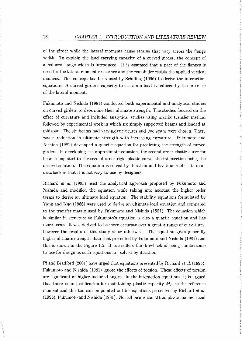
16 CHAPTER 1. INTRODUCTION AND LITERATURE REVIEW
of the girder while the lateral moments cause strains that vary across the flange
width. To explain the load carrying capacity of a curved girder, the concept of
a reduced flange width is introduced. It is assumed that a part of the flanges is
used for the lateral moment resistance and the remainder resists the applied vertical
moment. This concept has been used by Schilling (1996) to derive the interaction
equations. A curved girder's capacity to sustain a load is reduced by the presence
of the lateral moment.
Fukumoto and Nishida (1981) conducted both experimental and analytical studies
on curved girders to determine their ultimate strength. The studies focused on the
effect of curvature and included analytical studies using matrix transfer method
followed by experimental work in which six simply supported beams and loaded at
midspan. The six beams had varying curvatures and two spans were chosen. There
was a reduction in ultimate strength with increasing curvature. Fukumoto and
Nishida (1981) developed a quartic equation for predicting the strength of curved
girders. In developing the approximate equation, the second order elastic curve for
beam is equated to the second order rigid plastic curve, the intersection being the
desired solution. The equation is solved by iteration and has four roots. Its main
drawback is that it is not easy to use by designers.
Richard et al. (1995) used the analytical approach proposed by Fukumoto and
Nishida and modified the equation while taking into account the higher order
terms to derive an ultimate load equation. The stability equations formulated by
Yang and Kuo (1986) were used to derive an ultimate load equation and compared
to the transfer matrix used by Fukumoto and Nishida (1981). The equation which
is similar in structure to Fukumoto's equation is also a quartic equation and has
more terms. It was derived to be more accurate over a greater range of curvatures,
however the results of this study show otherwise. The equation gives generally
higher ultimate strength than that presented by Fukumoto and Nishida (1981) and
this is shown in the Figure 1.5. It too suffers the drawback of being cumbersome
to use for design as such equations are solved by iteration.
Pi and Bradford (2001) have urged that equations presented by Richard et al. (1995);
Fukumoto and Nishida (1981) ignore the effects of torsion. These effects of torsion
are significant at higher included angles. In the interaction equations, it is argued
that there is no justification for maintaining plastic capacity Mp as the reference
moment and this too can be pointed out for equations presented by Richard et al.
(1995); Fukumoto and Nishida (1981). Not all beams can attain plastic moment and

1.2. LITERATURE REVIEW
o.J
.. •·~t
0.1
... - -· ........, Dllic Clllt ,..._ n. &l I
- ........... EIIIicOnt -·----!-----.-· lr zc:: . ::pz
M·~ I ; ~ •1.543 ""'1~11::::"""-....;.,rr-~::::::oooll
~-_ ... _ ...
...... ..... ......
.........
,'
1.2 1.4
17
Figure 1.5: Comparison of Fukumoto and Nishida (1981) and Shanmugan et al. (2003) equations
thus it is not a good reference. The plastic moment capacity used in equations by
Richard et al. ( 1995); Fukumoto and Nishida ( 1981) ignores the moment resisting
contribution of the web. The omission of web contribution term mean that curved
hybrid and homogeneous girders will have the same capacity. However, this is not
explicitly stated in the application of the equations.
Shanmugan et al. (2003) conducted experiments on laterally supported curved
girders in which the curvature and slenderness were varied. The girders were
simply supported and also loaded at midspan. Bearing stiffeners were provided in
areas of load application and support. Finite element models were also created in
ABAQUS. The finite element model gave ultimate load values close to
experimental results for all the girders. It was observed that ultimate strength
reduces with increase in curvature. When the beam span is kept constant, it is
observed as expected that at a lower subtended angle the girder behaves almost as
a straight girder. The failure mode was also observed as web slenderness was
increased. At ~ = 288, the failure is similar to straight girders with significant t
tension field action. Parametric studies on girders with maximum span to
curvature ratios (L/R) of 0.1 and varying web slenderness were performed and it
was shown that in this range of curvatures, the curves are close to straight girder.
Generally there is a reduction in ultimate strength with increasing slenderness.

j
f
18 CHAPTER 1. INTRODUCTION AND LITERATURE REVIEW
Interaction equations have been used to predict the behaviour of curved girders.
The common equation is the circular interaction equation:
(1.4)
where Mp is major axis full plastic moment of the cross section, M is the major
axis bending moment, Tp is full plastic torque of the cross section and T is the
torsion. The circular interaction equation has been used by Yoo and Heins (1972)
to study the plastic behaviour of curved girders. Pi and Bradford (2001) have
pointed out the drawbacks associated with the circular interaction equation. The
reference Tp can not be defined accurately for nonuniform torsion of a curved girder
and the use of Mp as a reference is not justified in situations where lateral buckling
occurs. The circular interaction equation further ignores the effects of secondary
torsion and the minor axis bending. These effects become significant in curved
beams as deformations increase. Thus the circular interaction equation tends to
overestimate the interaction strength. Pi and Bradford (2001) have proposed an
alternative interaction equation based on finite element studies:
(1.5)
where Mu and Tu are the maximum nominal in-plane bending moment and torque
determined from first order analysis, Mbx is the nominal member capacity of the
corresponding straight beam with same length and same boundary conditions;
/x=2.0 and ls=l.O for continously braced curved beams; lx=l.5 and / 8 =1.0 for
centrally braced curved beams; lx=l.O; and / 8 =1.0 for un-braced beams.
Schilling (1996) derived a set of interaction equations relating the vertical and lateral
moments. For a compact section the relationship is based oa full section becoming
plastic under combined vertical and lateral moments. For compact flange section,
the average stress is less than the yield stress though some sections of the flange are
permitted to yield. For the non compact section, the whole section remains elastic.
The equations by Schilling (1996) do not make use of the un-braced length directly.
This has been pointed out by Yoo and Davidson (1997) as a weakness in using the
equations as a design tool. Yoo and Davidson (1997) have presented an alternative
set of equations with include un-braced length as parameter.
The Hanshin Expressway Corporation Guidelines developed an interaction equation
between vertical and lateral bending stresses (Hall, 1996). The lateral and bending

1.2. LITERATURE REVIEW 19
moments are to be computed using the V-load method and the interaction equation
is given below:
_b_ + fw < l.O (Fba)c Fbao -
(1.6)
where fa is the normal flexural stress, Fbac is the critical normal bending stress, fw
is the lateral bending stress and Fbao is the yield stress. The ratio of un-braced
length to radius is limited to 0.2. Davidson et al. (1999) investigated the effects of
curvature and slenderness on membrane stresses. As the curvature and slenderness
are increased, the membrane stress distribution becomes nonlinear through the
section depth. Thus in a curved girder the flanges have to carry more load. The
phenomenon described by Davidson et al. (2000b) has the same effect as the load
shedding observed in straight girders and the distinction between the two is
unclear. The lateral deflection of the curved panel also causes plate bending
stresses in the web panel.
Hall did an analytical study of curved girders and compared the results generated
from the various equations given by Fukumoto, Nikai and AASHTO Bridge Design
Specification (Hall, 1996). The AASHTO strength equations presented were a
modification of the lateral torsional equations given in the specification (Hall,
1996; Jung and W.White, 2006). It was seen that the different equations produced
qualitatively similar plots and tended to significantly underestimates test specimen
strength.
The notion of section class is still relevant when considering girder behaviour.
Section classifications of compact and non-compact that are used for straight
girders can still be used. Thus compact sections with appropriate bracing can
reach the plastic moment capacity and the non compact sections reach yield
moment. Schilling (1996) suggested an additional section class called compact
flange. Such a section satisfies the compression flange slenderness and bracing of a
compact section and the web slenderness of a non compact section. This allows a
larger lateral moment to be carries for a given vertical moment.
In a girder, the web carries the shear as well as keep the the flanges apart and thus
provide the lever arm. Although plates have been shown to posses significant post
buckling strength reserve, the onset of elastic buckling has been used in formulating
strength equations. The buckling modes important in a girder are listed below and
these are illustrated in Figure 1.6:
(i) web buckling due to bending in the web plane,

20 CHAPTER 1. INTRODUCTION AND LITERATURE REVIEW
(ii) buckling of compression flange in vertical direction,
(iii) buckling due to shear
Lateral buckling V rt' I b kcs:•;.::s:::s s;;::ssi;:s;;::ss::S::s\l'~Ttl:~rsional buckling
e1~ ucl Figure 1.6: Possible buckling modes of !-Girder scctionSalmon and Johnson (1996)
Basler and Thurlimann (1961) observed that the transition between pre buckling
and post buckling in webs is not accompanied by increased deflections. Thus it can
not be used as a limit for bending strength. This observation holds for hybrid beams
that web buckling due to bending or shear does not cause failure (ASCE-AASHO,
1968). The strength is determined by the failure of compression flange. Compression
flange buckling is treated by equating the critical buckling stress to the transverse
component of flange force. The slenderness limits are thus imposed on the web to
prevent vertical flange.
The major factors affecting buckling of compression flange have been identified as
warping stress gradient and torsional restraint by web. Research has been done to
determine the local buckling behaviour of curved girders (Culver and Frampton,
1970) using finite difference methods. The effects of flange-web rigidity and radial
stress on the plate buckling factor k and general local buckling behaviour were
investigated. Unlike the straight girders, the stress situation in curved flanges is
also affected by radial stresses. The radial stresses are tensile on outer half of flange
and compressive on the inner half. Because of the stress differences in these sections
of the flange, buckling occurs in the compressive half of the flange first. Culver and
Frampton (1970) showed that when the flange-web junction is assumed fixed, the
outer flange half buckles first and if the flange-web junction is simply supported
then the inner half buckles first. The relevant buckling coefficients k for different
panel aspect ratios and curvatures were obtained.
More recent studies by Davidson and Yoo (1996) using finite element analysis have
generally confirmed the Culver and Frampton (1970) findings. While Culver and
Frampton (1970) attributed the observed behaviour to geometry, Davidson and

1.2. LITERATURE REVIEW 21
Yoo (1996) have shown that the buckling behaviour can occur in a straight flange
with stress gradient. Further, the modeling of boundary conditions in the finite
difference technique was shown to be opposite to the effects observed in the finite
element model. The web has the effect of pushing the flanges in the radial direction
causing radial compressive stresses on outer half and tensile stresses on the inner
half of the flange. Davidson and Yoo (1996) performed parametric studies in which
boundary conditions, curvature, web thickness and length were varied. A simple
equation based on these studies has been presented equations that expresses the
buckling stress of the curved flange in relation to the straight one:
where
is the stress reduction factor,
Ucv is the curved girder stress,
Ucr is the elastic critical stress for straight girder,
lbr is the cross-frame bracing spacing,
R is the radius of curvature at web line and b1 is the flange width.
Alternatively limits are imposed on flange slenderness to prevent buckling:
- < - ~ (b) (b) t cv - t st
(1. 7)
(1.8)
where b and t are the flange width and thickness respectively, 1/Jcv is a reduction
factor that is applied to the straight girder equation. While the curvature affects
local buckling behaviour of a curved flange, the suggested correction parameter
only increases the straight girder slenderness by 2%. Limits on slenderness are also
imposed by the Japanese Guidelines to prevent local buckling (Davidson and Yoo,
1996). The limit increases the curved compression flange thickness over the straight
girder by 30%.
Abdel-Sayed (1973) investigated the bifurcation behaviour of curved web panels
under shear and combined shear and bending. The elastic critical load of the
curved panels were greater than corresponding flat panels. The model used did not
include flange-web and lateral torsional rigidity. Davidson et al. (2000a)
investigated curved web panels using finite element analysis. The results showed
that curvature results in an increase in the elastic critical loads. Further, when

22 CHAPTER 1. INTRODUCTION AND LITERATURE REVIEW
pure bending was dominant, no bifurcation was observed while when pure shear
dominates bifurcation was observed near the elastic critical load.
Bifurcation buckling of cylindrically curved web does not occur under shear due to
the out of plane bending actions resulting from curvature. A curved web behaves
like a column with initial deformation. Lee and Yoo (1998) have shown through
numerical models that curvature increases the linear buckling strength of a web
panel though no design equations were presented. The finite displacement behaviour
under pure shear showed a bifurcation type behaviour at or near the elastic buckling
stress.
Several equations for critical elastic moment of curved girder have been put forward
from each of the different curved beam theories. The equation presented in the
Guide (Galambos, 1998) is that derived by Nishida given below:
(1.9)
where !y, J and Cw are minor axis moment of inertia, St.-Venant torsion constant
and warping constant. The equation 1.9 above shows that there is a reduction in
critical moment with increasing curvature. It is noted that there is no universal
agreement on the bifurcation stability equations of curved girders.
The issue of bracing in curved girders is treated differently because unlike in straight
girders, the bracing and cross frames are primary load carrying members. The
braces perform two functions; to prevent the buckling and to limit the lateral flange
bending. The limits imposed on the brace spacing are thus to satisfy the above
mentioned functions. While other factors such as vertical bending and deflection are
considered, the critical parameter in cross frame spacing has been shown to be the
warping stresses. Davidson et al. (1996) investigated the issue of cross-frame spacing
using finite element models. The parameters varies included girder depth, span
length, number of girders, girder spacing and flange width. The results obtained were
fitted into an equation using regression to obtain a spacing length. Yoo and Littrell
presented a formula to satisfy these conditions and it is this formulary presented in
the Guide (Galambos, 1998). However, the modeling was not adequate, no proper
mesh refinement was done and only effects of span and radius of curvature were
considered, thus making the limits unconservative (Davidson et al., 1996).
The behaviour of curved girders under shear has been investigated by several
researchers (Jung and W.White, 2006; Lee and Yoo, 1998; Abdel-Sayed, 1973).
1.2. LITERATURE REVIEW 23
Shear strength can be limited by plate buckling or yielding. However, the yield
condition can only occur in compact webs. The critical stress in a plate is given by:
rr2Bkv (t) 2
Tcr = 12(1- v 2 ) b (1.10)
were t is the plate thickness and b is plate height and k is the shear coefficient.
Early theories on web shear assumed that the web was simply supported (Basler
and Thurlimann, 1961). Basler model assumes simple support flange-web
boundary condition and provides a lower bound for web shear resistance. However,
finite element analysis studies by Lee and Yoo (1999a) have shown that the
boundary conditions are more towards the fixed condition, making the simply
supported assumption conservative. The boundary condition is dependant on
flange rigidity. Lee and Yoo (1999a) suggested the use of shear buckling coefficient
for flange-web thickness ratio t f /tw ~ 2.0 given below:
k = kss + 0.8(ksf - kss) (1.11)
where k88 is the shear buckling coefficient for rectangular plates simply supported on
all four edges and ksf is the coefficient for rectangular plates with two opposite sides
simply supported and fixed respectively. Hybrid girders under combined bending
and shear behave differently from homogeneous girders. This is because web yielding
due to bending reduces web stiffness. Due to insufficient data on hybrid girder
shear behaviour, the ASCE-AASHO (1968) suggested a conservative shear design
procedure that neglects tension field action. Studies using finite element models by
Shanmugan et al. (2003) investigated curved girders using finite element models and
tension field action is indeed present in slender curved members.
The buckling strength of curved web panels has been shown to be greater than that
for a corresponding straight web (Lee and Yoo, 1999b; Abdel-Sayed, 1973). Abdel
Sayed (1973) did an analytical study of curved panels under combined shear and
bending. Shear buckling coefficients for curved panels were obtained and it was
shown through a plot that for a given panel aspect ratio, the buckling coefficients
are greater than those for a straight panel. Lee and Yoo ( 1999 b) have shown that
the ultimate shear strength for a panel reduces with increasing curvature. Defining 3
a curvature parameter c = Ra where R is the radius of curvature, a is the panel 8 lw
arc length and tw is the web thickness, Lee and Yoo (1999b) showed that for c :::; 1.0
the ultimate strength of a curved panel is not significantly different from a straight
one. It was shown further that curved panels can develop significant post buckling

24 CHAPTER 1. INTRODUCTION AND LITERATURE REVIEW
strength. This post buckling strength reserve for curved webs is ignored in AASHTO
Guide Specifications (1993) (Lee and Yoo, 1999b).
For vertical flange buckling the LRFD (Salmon and Johnson, 1996) gives the limit
for a straight girder web:
h 96500 (1.12)
JF':j(Fyf + 114)
where h is the web height, tw is the web thickness and Fyf is the flange stress.
Shear buckling reduces the distance between flanges reducing this reduces load
carrying capacity. Carskaddan (1968) recommends treating the shear buckling
strength to be the ultimate strength for un-stiffened hybrid girders. However,
plates posses significant post buckling reserve strength and this would be
conservative. The design practice is to impose limits on the slenderness ratios so as
to preclude local buckling.
Early studies by Japanese researchers on local flange buckling showed that curvature
effects can be neglected within certain curvature limits (Davidson and Yoo, 1996). b
These limits are given as Rw « 0.05 where b is the compression flange half width
and Rw is the radius of curvature of the web line.
Curved !-girders have been modelled using finite element methods. The finite
element method has the advantage of accurately represent the capacities due to
local flange buckling and lateral torsional buckling, both in terms of the resistance
of the cross-section and in terms of the deflected shape (NCHRP-Report-563,
2006).
The studies of curved girders have covered a wide range of cases from modeling
composite girder bridges, the study of girders with openings and the shear lag in
curved girders. In general, commercially available software packages such as
ABAQUS have been used. Richard et al. (1995) used a variation of both linear
triangular elements and bilinear quadrilateral elements to study the effects of
radius of curvature to span effects and residual stresses on the ultimate load
carrying capacity. Linear triangular elements were used. These triangular elements
provide efficiency in computational time though they yield less accurate results
when coarse meshes are used and also lock out shear. Quadrilateral elements allow
shear deformation. The material was modelled as non linear using an incremental
plastic theory and assuming the material is elastic-plastic with strain hardening
rate dependent.

1.2. LITERATURE REVIEW 25
These studies have shown that the ultimate strength of thin walled girders is
dependent on factors such as type of loading, span length, curvature, initial
residual stresses and boundary conditions. Richard et al. (1995) investigated the
second order in-elastic effects of curved beams using finite element analysis. Mixed
element models were used. This was compared with experimental results obtained
by Fukumoto and Nishida (1981) and analytical results obtained from the
differential equations of equilibrium derived by Yang and Kuo (1987). Simply
supported curved beams and beams with intermediate supports were studied. The
results obtained in simply supported case showed that the ultimate strength of
beams with smaller curvature was always higher than the beams with larger
curvature. The equation was found to be more conservative than the ABAQUS
model up to a maximum of 35% in some cases.
Chung and Sotelino (2006) used models with either shell elements or a combination
of shell and beam elements. When using a mixed model, the shell elements were
placed at the centroid of girder flanges while beam elements were placed at the
girder web. Rigid links were applied through constraints in degree of freedom to
model composite action. A comparison of these model with experimental results
revealed maximum error of 6%. It was found when modeling in ABAQUS that
overlapping flange elements with web elements by sharing the same node resulted
in significant modeling errors because of the incorrect moment of inertia about the
primary bending axis.
An experimental and analytical study on curved girders was conducted by Zureick
et al. (2000). Three curved girders held together by cross frames were assembled.
The finite element model utilising four types of elements in ABAQUS was
developed. As with other researchers shell and beam elements were used in
addition to unidirectional gap and super elements. S4R elements in ABAQUS were
used to represent girder web, flange and stiffener plates. This element can model
thin or thick shells, finite membrane strains and large strains. Zureick et al. (2000)
conducted further experiments investigating post buckling shear response of
!-girders. The results from these experiments were analysed by Jung and W.White
(2006) in finite element models. The objectives of the study was to present finite
element analysis results based on the experiments of Zureick and parametric
variations. A displacement based bilinear quadrilateral shell element with reduced
integration was used in the model. The strength of the girders in experiments were
between 89% to 97% of the finite element analysis.

26 CHAPTER 1. INTRODUCTION AND LITERATURE REVIEW
A comprehensive treatment of finite element analysis involving arbitrary curved
beams is given by Saje et al. (1998). The formulation is based on Reissner non linear
beam theory. Large displacements and rotations were allowed and an arbitrary
curved beam considered. A range of techniques including use of strain elements,
hybrid and mixed element formulations were applied. The formulation results in
a model where only the rotation function need to be interpolated. Internal forces
are calculated with the same accuracy as displacements and rotations. Further,
unknown variables correspond to the fixed in space coordinate system structure
thus there is no need for local to global coordinate transformation. The later results
in increased computational efficiency.
1.3 Research motivation
The review shows some of the work going on in the area of both hybrid and curved
girder research. Efforts have been undertaken to derive curved beam equations
but no generally agreed formulation exists. The approach to simplify equations
from strength of materials-small deflection theory considerations have resulted in
equations that either break down when the curvatures are large or equations that
are cumbersome to use by designers. For hybrid girders, research has shown that
they behave almost like homogeneous girders. However efficient design of hybrid
girders is curtailed by the restrictions on high performance steels that have yield
strength greater than 490MPa. For such steels, inelastic moment redistribution and
hence plastic design are not permitted. Hybrid curved girders have not been covered
and are the focus of this study.
In the absence of curved girder equations, research on inelastic curved girder
behaviour is hampered. Numerical techniques such as finite element analysis
remain the main investigative tool to develop semi-empirical design guides. With
increasing computational power, finite element models have been employed in the
study of the behaviour of both curved and hybrid girders and valuable
recommendations based on these studies have been presented. As in the case of
other techniques, the reliability and validity of finite element analysis for curved
girder studies has been highlighted as an area that needs research
NCHRP-Report-563 (2006). The report points out other areas of research which
include the yield criterion, the validity of analysis tools, the development of
interaction equations and extreme event dynamic behaviour of curved girders.

1.3. RESEARCH MOTIVATION 27
1.3.1 Problem definition
Curved bridges are often the best alternative to straight girders when predefined
road or railway alignments or presence of buildings place constraints on design.
This happens in urban environments and even remote locations. Horizontally
curved girders experience lateral moments when subjected to gravity loads and
this alters their load resistance capacity. Hybrid girders arise due to the need of
building structures that are less imposing on the environment or the need to
reduce overall dead weight in long span bridges. Such girders utilising high
strength steel offer economy. The different steel combinations in hybrid girders
coupled with the presence of curvature complicates the analysis of curved hybrid
girders.
1.3 .2 Research aims
The following areas investigated in this study:
(i) The effect of varying curvature on the girder load-deflection behaviour
Girder behaviour changes as horizontal curvature is introduced. This is because
a curved girder caries both lateral and vertical moments. The load carrying
capacity as curvature is changed is examined for selected span lengths.
(ii) Stress-strain variation in the girder
The stress-strain variations both through girder depth and across the flanges
are investigated. The stress distribution has a bearing on plastic hinge
formation and affects areas prone to local buckling. The stress-strain profile
for a curved girder is different from that of a straight girder due to the
presence of lateral moments. The stress variation is also of interest because of
the different steel grades used in flange and web.
(iii) Effect of varying steel grades in girder
The hybrid effects are studied by varying steel grade in web and flange. For
hybrid girders optimised to carry moments, the web yields because it has steel
with low yield strength. In the inelastic range, the modulus of the web reduces
after yielding and this results in slight stiffness reduction for hybrid girders.
The load-deflection response of the curved hybrid girder is thus of interest after
the web has yielded.
(iv) The accuracy of available ultimate load equations
The behaviour of curved girders is still an area of investigation and no generally

28 CHAPTER 1. INTRODUCTION AND LITERATURE REVIEW
agreed equations exist for curved girders. The effectiveness of available design
procedures and accuracy of available ultimate load equations is examined and
compared to finite element analysis results.
1.3.3 Scope of research
This study is limited to the following:
(i) Hybrid girders that are optimised for moment capacity. Such girders have high
yield strength steel in the flanges and low yield strength steel in the web.
(ii) A cross section of 812 x 300 (8,16) is used for the investigation. The effects of
local buckling as slenderness ratios are varied are not investigated.
(iii) Two spans of 5m and 8m are used for the investigation.
(iv) Three steel grades with yield strength of 350MPa, 460MPa and 690MPa are
used for the investigation.
( v) Computational modeling is used for the investigation. Laboratory experiments
are not done, however, the experimental data available from literature is used
to verify the model.
1.3.4 Research limitations
The resources in both time and money did not allow for any scaled laboratory model
test. The lack of experimental tests lead to great reliance on the two readily available
experimental data sets for calibration. The experimental data used for calibration
was on curved homogeneous girders, data on hybrid curved girders was available for
model verifications.
The finite element method has been shown from the literature review to give results
close to experiments for the curvature ratios adopted in this study. However, the
reliability and range of applicability of the finite element method to curved girder
problems is still an area of investigation and this has been highlighted in NCHRP
Report-563 (2006).
The effect of curvature on girder behaviour is investigated. In this respect, the
girder arc length and span are not significant parameters. The major parameter
used is curvature ratio and this is varied to within limits given in the literature
1.3. RESEARCH MOTIVATION 29
review. Thus only two spans are used and in this study, the arch length to radius
of curvature ratio is used to compare the girder results.
The study is limited to three steel grades and this is purely due to the limitation
on available data which included one mild steel grade and two high strength steel
grades.
The curvature modifies the lateral and stress pattern in the girder. The investigation
focuses only on the curvature and hybrid effect on ultimate load of a girder and
therefore local buckling is not investigated. In this regard, only one girder cross
section is used.

Chapter 2
Theory
2.1 Introduction
This chapter presents an overview of the principles that govern hybrid girders,
curved girders and the expected behaviour of curved hybrid girders. The theory
governing straight girder behaviour is given first. Later, the areas of departure
from this straight girder behaviour are shown through the consideration of hybrid
and curvature effects. Design equations, interaction equations and modifications to
slenderness limits are also presented.
Plate girders are large flexural members fabricated from plates. In recent years,
there has been a shift from bolts and rivets when fabrication girders. Welds are
now extensively used and they are a more aesthetically pleasant form of connection.
Girders are optimised to carry large flexural loads over long spans that can not
be carried by available hot rolled members. The applications of plate girders is in
highway bridges and buildings with large open spaces. Unlike hot rolled sections,
girders offer greater flexibility to the designer in proportioning members and also
in material selection. Girders do behave differently from other flexural members
such as hot rolled beams. This is mainly because girders are deep and thus the web
tends to experience web buckling. The web stress relationship also deviates from
the linear beam theory through the depth.
Hybrid girders have been studied extensively and the review shows that the studies
did not cover the combined hybrid-curvature effects. This is the area of investigation
in the current study. Hybrid girders have already been defined as girders with
different steel grades in flanges and the web. The present study investigates hybrid
girders with higher steel grade in the flange and lower grade steel in the web. The

2.1. INTRODUCTION 31
development and availability of high strength steel and the need for economy are
the primary reasons for considering hybrid girders in design. The research on hybrid
girders has largely been on rotational ductility to assess the attainment of plastic
capacity and moment redistribution especially in areas of negative flexure (Barth
et al., 2007; Ito et al., 2005; Azizinamini et al., 2004; Miki et al., 2002; Sause and
Fahnestock, 2001). The research has resulted in revision of design code requirements
regarding use of HPS from a steel yield limit of 345MPa to 490MPa for plastic design
and moment redistribution.
Numerous theories of curved beam have also been put forward (Yang and Kuo,
1986; Yoo, 1982; Fukumoto and Nishida, 1981; Vacharajittiphan and Trahair,
1975; Vlasov, 1961; Timoshenko, 1961). A comparison of closed form solutions for
elastic critical moment obtained show the wide differences in predictions of critical
loads. The differences are due to assumptions regarding warping, differences in the
formulations of the theories, approximation procedures for curvature terms and
interpretation of vanishing shear assumption in thin walled members. There is no
accepted set of equations for the general case of thin walled curved beams. The
absence of such equations has reduced progress in the study of inelastic behaviour
of curved girders.
Despite the absence of generally accepted curved beam equations, research has
progressed and equations for ultimate strength have been put forward together
with semi-empirical interaction equations. Numerical techniques such as finite
element analysis have also been used to study curved girder behaviour. Design
guidance is provided that gives some rules on the design of curved hybrid girders
(ASCE, 1977). There are two design guides that cover curved girders; Hanshin
Guide and AASHTO Guide Specifications. What is presented here are the
guidelines adopted in the AASHTO Guide together with background literature.
This is largely because of no access to the Japanese codes or literature on curved
girder research in Japan.
When designing hybrid girders, the approach is to consider a homogeneous girder
and then apply hybrid reduction factors (Salmon and Johnson, 1996). For curved
girders, the curvature can be ignored for small curvatures. The ASCE (1977) gives
guidelines for general flexural behaviour of both curved homogeneous and curved
hybrid girder design. It is thus important as a starting point to outline the general
flexure theory for straight homogeneous girders and highlight areas of departure as
hybrid and curvature effects are introduced.

32 CHAPTER 2. THEORY
2.2 Plate Girder behaviour
Plate girders are welded plate assemblies and the present study only considers !
girders. The process of manufacture which involves welding different plates also
introduces residual stresses that can be significant. Imperfections are also introduced
in manufacturing and assembly process and these have an influence on both buckling
behaviour and yield pattern.
The general experimental and theoretical basis for girder design was done by Basler
and Thurlimann (1961). Background work on diagonal-tension theory for shear
capacity had already been presented by Wagner. The main difference between beams
and girders is the web behaviour which in most cases is non-compact. Modifications
have been suggested to the theory by Basler in recent years, however due to the
simplicity and relative accuracy, its equations or their modification appear in many
codes including the SAN 10162.
The bending resistance contribution from the web in a girder is rather small. Only
a small strip of the compression part of the web estimated to have a depth of 30tw
and the tension part are considered for flexural resistance (Basler and Thurlimann,
1961). Even under combined bending and shear, it has been observed that shear
buckling of the web can not be used as a limit for load carrying capacity. Ultimate
moment considerations are thus based on local compression flange buckling, vertical
buckling of flange into web and lateral torsional buckling of the girder.
2.2.1 Buckling
A beam or girder can fail by yielding or buckling when subjected to moments.
The instability situation is especially significant when thin walled members such
as girders are loaded. This instability can be due to lateral torsional buckling or
buckling of compression flange into the web. The elastic stability of beams has been
investigated by many authors such as Trahair and Bradford (1988), Vlasov (1961)
and Timoshenko (1961). For a simply supported doubly symmetric section under
uniform bending in the web plane, the governing differential equations are given
below (Tall, 1974):
d4y cf2cp E I Y dz4 + M dz2 = 0 (2.1)
(2.2)

2.2. PLATE GIRDER BEHAVIOUR. 33
where Iy is the moment of inertia about y-axis, u is the displacement in the x-axis,
<P is the angle of twist, Cw is the warping torsional constant, G is the shear modulus,
Kr is the St Venant torsional constant.
The solution to the above equations is given below:
(2.3)
where J and Cw are torsional and warping constants.
The above case is the simplest and many practical cases can be dealt with by starting
with equation 2.3 and applying modifications. The modifications come in form
of a factor that is given for particular cases depending on loading and boundary
conditions.
Plate girders are made by welding different plates together and thus the behaviour
of plates gives some idea on how the assembly behaves. The plate elements of a
girder can reach instability through the following:
(i) Elastic bend-buckling strength
(ii) Elastic shear-buckling strength
(iii) vertical flange buckling
When transverse loads are applied to a plate, the critical stress is reached and this
is given in the equation below:
(2.4)
where k is the plate buckling coefficient, t is the plate thickness and b is the plate
width.
The equation 2.4 holds for plates subjected to shearing forces and compression
forces. However, the buckling coefficient is calculated differently for these cases.
When calculating the critical stress for plate assemblies, the restraint offered by the
joints can be significant. For a long plate subjected to bending k depend on the
plate support conditions and for simple supports k = 23.9 while for fixed supports
k = 39.6. Clearly the two values represent the lower bound and upperbound for
all girder configurations. It is common to proportion girders such that the flange

34 CHAPTER 2. THEORY
offers some restraint to web bend buckling. The AISC procedure assumes the fixity
condition to be 80% toward the the fixed condition (Salmon and Johnson, 1996)
A similar procedure to determine critical shear stress is used. The buckling stress is
given by the equation similar to equation 2.4 and the buckling coefficients presented
(Trahair and Bradford, 1988)
Tcr = 1r2 Ekv (-bt) 2
12(1 - v2 )
h where for L ::::; 1
k -4 0 5.34 .- . +G)' h
and for-> 1 L-4.0 kv = 2 + 5.34
(~) h and L are the plate height and width respectively.
(2.5)
(2.6)
Lee et al. (1996) has shown that the web-flange boundary condition is dependant
on the thickness ratios of flange and web. After conducting numerical investigations
on the boundary conditions and the following equations were proposed for the shear
coefficients, where t f is the flange thickness and lw is the web thickness:
For ~ < !!._ < 2 2 lw
k = k + - (k f - k ) 1 - - 2 - -4 [ 2 ( tf )] ss 5 s ss 3 lw
For !!._ > 2 tw
4 k = kss + S (ksf - kss)
(2.7)
(2.8)
Note: kss is given by the shear coefficients given earlier as kv. The case where
two opposite edges of a plate are simply supported and fixed respectively is also h
presented below: For L < 1
5.34 2.31 ( I ) ksf = (hj £) 2 + (h/ L - 3.44 + 8.39 h L

2.2. PLATE GIRDER BEHAVIOUR
h For-> 1 L-
5.61 ksf = 8.98 + (h/ L) 2
1.99
(h/ L) 2
35
The equations for ksf presented above are similar with the equations for short plate
with clamped edges given in the (Galambos, 1998).
Basler and Thurlimann (1961) proposed the following limits for web slenderness:
where ~~ is the ratio of web to flange area, E 1 and (J 1 are the strain and stress in
flange respectively. In general the ratio ~~ is 0.5.
Analytical studies on both stiffened and un stiffened plates have been done and these
provide an insight into plate girder behaviour. Local and global buckling modes can
be significant in affecting failure mode. In design practice the buckling types above
are treated separately even though there can be interaction between lateral, torsional
and local buckling. This is a simplification to obtain closed form solutions for the
lateral and torsional buckling. Local buckling is prevented by careful choice for plate
slenderness parameter. Section classification is used a way to determine the extent
to which local buckling affects the section capacity to develop the design moment.
Different design guides give limits and below are extracts from some of the standards.
Though expressed differently, there is a connection between the local buckling limits
and the material yield stress. Numerical studies such as finite element analysis are
used to investigate the lateral, torsional and local buckling interaction and this is
used in the current study.
The SANS 10162 gives the limits for flexural members presented in Table 2.1. The
classes are as follows:
(i) class 1 sections will permit attainment of the plastic moment and subsequent
redistribution of the bending moment;
(ii) class 2 sections will permit attainment of the plastic moment but need not
allow for subsequent moment redistribution;
(iii) class 3 sections will permit attainment of the yield moment; and

36 CHAPTER 2. THEORY
(iv) class 4 sections will generally have local buckling of elements in compression
as the limit state of structural resistance.
Table 2.1: SANS10162 Section classification
Section classification Element in compression ---------------
Class 1 Class 2 Class 3
I or T -section flange b 145 -<--t - ..j"Fy hw 1100 hw 1700 hw 1900
Web -<-- -<-- -<--tw - Fy tw - Fy tw - Fy
where hw and tw refer to web height and thickness respectively and Fy is the steel yield stress.
The Euro code 3 follows a similar procedure, the classes are just as defined in above
for SANS61-1 (EN1993-1-1). The limits are given in the Table 2.2:
Table 2.2: EN3-1-1 Section classification
Element Class 1 Class 2 Class 3
Internal compression part ~ < 72e c ~ < 124e - < 83e t - t - t -
Outstand flanges c ~ < 10e
c - < 9e - < 14e t - t - t -
where e = J235/ /y and /y :::; 460MPa
2.2.2 Bending
The stress distribution in a girder differs slightly from that of a beam. The
compression web carries less load than that predicted by beam theory. Some of the
compressive force is redistributed to the compression flange. The compression
resistance of the web in the compression part is ignored except for a small section
next to the flange. The strength of the compression flange largely determines the
moment capacity of a girder. The compression flange can fail by lateral, torsional
and vertical buckling. These aspects have already been reviewed in section before.
Having proportioned a girder not to fail though local buckling, the bending strength
is determined. In SANS 10162 the factored moment resistance for class 1 or 2 doubly
symmetric sections for is given as follows:

2.3. HYBRID GIRDERS 37
Neutral Axis ./~Beam theory
./ stress
Figure 2.1: Girder stress
(i) when Mer > 0.67 Mp
( 0.28Mp)
Mr = 1.15¢Mp 1 - Mer but not greater than ¢Mp
(ii) when Mer ~ 0.67 Mp
where: Mer is elastic buckling moment given in equation 2.3,
MP is the plastic moment resistance capacity given as Mp = ¢Zpjy,
For class 3 or 4 sections, Mp is replaced with My given as My= <PZefy,
Zp and Zp are plastic section modulus and elastic section modulus respectively and
!y is the steel yield strength.
For a web exceeding class 3, the moment resistance from above is modified and Mr
is limited to M; as follows:
where Aw = hwtw is the web area
A f is the flange area
Mu is the actual moment in girder under ultimate load.
2.3 Hybrid girders
(2.9)
The theoretical behaviour of straight hybrid beams was outlined by Frost and
Schilling (1964) and the relevant equations are simply repeated here. In the

38 CHAPTER 2. THEORY
Mp -------- -..;:-~--:,::-....,-~----(3)
Curvature <1>
Figure 2.2: Moment deflection for hybrid girder
flexural behaviour of hybrid girders, it is important to define yield. This is because
in hybrid beams, the web is designed intentionally of lower yield steel as compared
to the flanges. In line with moment capacity definitions for homogeneous girders, a
plastic moment capacity can be expected if buckling is prevented and enough
rotational ductility is mobilised. At plastic moment, the whole section is
considered to be yielded. Though infinite rotation is required for whole section to
yield; such a mathematical abstraction is very useful as strain hardening and
inelastic behaviour allow this capacity to be reached without the centre of the web
yielding.
The concept of plastic section is useful, but severe restrictions on the slenderness
limits and bracing requirements are necessary to attain it. Another important point
is the initial yield at the extreme fibres of the flange or simply referred as flange
yield. In this case, sections of the web yield before the extreme fibres of the flanges
yield. The girder is expected to have load deformation behaviour shown in the
Figure 2. 2. The first stage consists of elastic deformations and there is no difference
with homogeneous girder. The behaviour exhibited in the elastic range is the same
for both straight and curved girders in that hybrid and homogeneous girders show
no difference. This is followed by the yielding of the web and later the flange yields.
Some insight can be gained in the flexural behaviour of a straight hybrid girder using

2.3. HYBRID GIRDERS 39
Bernoulli-Euler theory. For this to apply, a straight girder adequately braced and
proportioned such that local buckling does not occur is considered. For a straight
beam under pure bending, the strains are proportional to the distance from the
neutral axis. The general differential equation together with flexure formula are
given below:
M = EJ,.., (2.10)
where M is the moment and ,.., is the curvature term and
My (7 = ---
! (2.11)
where y is the distance from neutral axis.
For simplicity, a perfectly elastic plastic material is considered with yield stress of
uy. For small loads the stresses are determined from Hooke's law using equation
2.11 and remain within the elastic range. In this zone, the load deflection curve is
linear. When the load is increased, the web yield is reached and this results in the
extreme fibres of the web undergoing plastic deformation.
Figure 2.3: Hybrid girder stress distribution
As the load is increased, the linear variation of strain is maintained but the stresses
in the web reach yield value. For the consideration of moment capacity, the web
contribution is small and thus the changes in the load deflection curve resulting
from web yielding are small. In this range of loading, the moment capacity is given
below:
(2.12)
When the load is increased further, the depth of the yield zone for the web increases
and the strains in the extreme fibres of the flanges begin to yield. This results in
significant increase in deflection for a given load due to the loss of stiffness. This

40 CHAPTER 2. THEORY
is expected as the flanges are primarily the moment carrying components. The
moment capacity is given:
(2.13)
Finally with increasing load, the remaining elastic zones of the web yield the moment
is given as:
(2.14)
In line with the concepts of yield moment and plastic moment for homogeneous
girders, the following are calculated from the expressions (Frost and Schilling, 1964):
Plastic moment:
(2.15)
Flange yield moment:
(2.16)
It has been recommended that the design of hybrid girders be based on moment
causing initial flange yield (Frost and Schilling, 1964). Plastic moment capacity
requires more bracing and more deflections to be reached and thus is considered
not a practical limit. Due to initial yielding of the web and the differences in steel
yield strength of the web and flange, other considerations such as deflection limits
have to be assessed. When a moment larger than twice the yield moment is applied
to the girder, inelastic action occurs under unloading. Frost and Schilling (1964)
recommended that the ratio of yield strength of the flange and web steel is kept
less than two. This restriction is also imposed by the Euro codes 3-1-5 (Veljkovic
and Johansson, 2004). The limitation on the steel strength ratio is more stringent
in AASHTO (2007) in that the lower yield still must be the greater of 250MPa and
70% of the higher steel flange AASHTO (2007).
2.3.1 AASHTO LRFD Approach
A first principles approach to design of hybrid girders is useful in appreciating the
yield pattern involved. However, design guides such as the AASHTO (2007) follow a
different approach as recommended by ASCE (1977). The nominal moment strength

2.3. HYBRID GIRDERS 41
is calculated by assuming a homogeneous girder made of flange steel and a reduction
factor is applied to account for hybrid effects (Salmon and Johnson, 1996; ASCE,
1977; Frost and Schilling, 1964). The reduction factor gives the ratio of the flange
yield moment of a hybrid section to that of a homogeneous section consisting of
flange steel. It is suggested here that as a consequence of the above simplification,
the section classification of a hybrid girder proceed as done in a homogeneous girder.
The equation for moment capacity of a hybrid girder is presented as a modification
of a homogeneous section is given below:
(2.17)
where Re is the reduction factor accounting for web yielding prior to initial flange
yield, Rpc is the reduction due to web bend buckling.
AASHTO (2007) gives the hybrid reduction factor Rh which is applied to equivalent
homogeneous beam. This factor first proposed by ASCE (1977) is given as follows:
R _ 12 + /1(3p- p3)
h- 12 + 2/1 (2.18)
where: 2Dntn Fyw
/1 =-A--, pis the smaller of -1
and 1.0, Jn n
A fn is the sum of the flange area and the area of any cover plates on the side of the
neutral axis corresponding to Dn (mm2),
Dn is the distance from neutral axis to the inside face of the flange on the side of
the neutral axis where yielding occurs first,
fn is the largest of the specified minimum yield strengths of each component included
in calculation of Afn· The factor Rh is always close to unity (AASHTO, 2007).
Restrictions are placed on the ratio of yield strengths by the AASHTO (2007). The
web steel should be the larger of 250MPa and 70% of the higher strength flange
steel. In general the difference between the steel should be one grade up. This
condition will clearly not be upheld in the present study first because it is the
general behaviour of hybrid girders that is of interest and second because of the
restriction placed due to the available steel stress-strain data for the study.
Since the web yields first, the support offered by the web to the flange is of interest.
The yielding of the web in the compression zone of the girder does not compromise
its ability to prevent flange vertical buckling. Also the lateral torsional buckling is
only sightly affected by web yielding.

42 CHAPTER 2. THEORY
2.3.2 EN3-1-1 Approach
The relevant code EN 3 does not make reference to design of hybrid girders.
However, a design procedure based on modifications of EN 3 has been put forward
by Veljkovic and Johansson (2004) and this is summarised in sections that follow.
Section classification
The section classification is done as given in section 5.5 of EN3-1-l. The web is
classified using the flange steel strength and this is considered conservative. The
above procedure implies that there should be no distinction in classification of both
homogeneous and hybrid girders. There is a limit of 460 MPa for the steel used.
Bending moment
In general, a girder has the same amount of steel in the web as in the two flanges
combined. The lever arm for the web steel is less and the web contributes less than
25% of the bending resistance in a homogeneous girder. The code allows the design
to be based only on flange class if the web is assumed not to contribute to the
bending resistance. Depending on class, the bending resistance is given below:
(i) Cross-section 1 and 2: The contributions of the web and flange are simply
added up and the moment resistance is given below;
(2.19)
where fYt and fyw refers to the yield stresses for flange and web steel
respectively; t 1 is flange thickness, hw and Aw refer to web height and area
respectively.
(ii) Cross-section classes 3 and 4: The flanges should be class 3 or lower. The
effective cross-section of web is determined by the yield strength of the
compression flange. The approximate formula for the bending resistance is
given below:
(2.20)
where

2.4. CURVED GIRDERS 43
when hwftw 124c
( )
2 2+ ~ .6.W == h A 1- Jyw /yt
w w f 12 yf
The interaction between shear and bending is ignored for class 1 and 2 while the
rules for interaction are applied for class 3 and 4.
The yield strength ratio for the flange and web is limited to 2. Within this limit,
the reduction of stiffness due to web yielding is considered small. Larger strains and
thus deflections are required for high strength steel to reach yield. Serviceability
requirements have to be reviewed to enable efficient use of such steels. In comparison,
the EN3 approach is less flexible compared to AASHTO approach when applied to
curved girders. The approach is along the first principles and is not easily modified
to give results for curved girders. The AASHTO design approach suggests that
cross-section class can be based on homogeneous girder and this is taken up by
EN3-l.
2.4 Curved girders
Curvature in girders results in lateral moments in addition to vertical moments.
The lateral moments causes stresses that vary linearly across the flange while the
vertical moments cause stresses that vary through the web depth. This significantly
changes the load resistance pattern of these girders.
The presence of a lateral moment has the effect of reducing the vertical bending
resistance of a girder. This can best be explained using the concept of a reduced
flange section presented by Schilling (1996). In this concept, a portion of the flanges
is assumed to resist lateral moments and the remaining section resists the vertical
moments. It therefore follows from the above and has been shown by experiment
that a curved girder will have less flexural capacity as compared to a straight girder
of similar proportions under similar loading and boundary conditions (Shanmugan
et al., 2003; Richard et al., 1995; Fukumoto and Nishida, 1981).

44 CHAPTER 2. THEORY
+ Figure 2.4: Warping and vertical bending stresses
2.4.1 Curved girder equations
From the literature review it is noted that two approaches have been used to
derive curved beam equations. The approaches are the equilibrium method used
by Timoshenko ( 1961) and Vlasov ( 1961) and the other approach being the energy
method which has generally been embraced by more recent researchers including
Kang and Yoo (1994a); Yang and Kuo (1987); Yoo (1982)
Vlasov Equations
Vlasov presented a theory of thin walled members that was not restricted to the
Navier hypothesis of plane sections (Vlasov, 1961). This restrictive hypothesis is
replaced by the notion of sectorial areas. The Vlasov equations have been the
starting point of other researchers such as (Heins, 1975; Yoo and Heins, 1972) and
the concise form given here is taken from Heins (1975).
Consider an element subjected to six external loads shown in Figure 2.5: three
distributed loads Qx, Qy and Qz all acting in the respective axes of the element and
three distributed torques mx, my and mz acting in respective girder axes.
Resisting internal forces are generated as a result of the external forces. These are
shearing forces Qx and Qy; normal force Nz; bending moments Mx and My and
torsional moment T. The force increments are shown over a length dz. The basic
equilibrium equations have to be satisfied.
From Figure 2.6, the forces in X direction are summed below:
(2.21)
Forces in Y direction:
(2.22)

2.4. CURVED GIRDERS
dz
L
X
y
Distributed torques
y
QX + aQX dz az ar
T+-dz az
45
N aNxd +- z X az
aM MY+--Y dz az
Qy + aQY dz az
Distributed loads
Figure 2.5: Forces on a curved girder element (Heins, 1975)

46 CHAPTER 2. THEORY
Forces in Z direction:
EJNz Qx [)z - R +qz = 0 (2.23)
Moments about X-axis:
8Mx T 8z + R -- Qy + mx = 0 (2.24)
Moments about Y -axis:
8My ---a;-+my +Qx = 0 (2.25)
Moments about Z-axis:
EJT Mx [)z +R+mx =0 (2.26)
The above six equations are reduced to only three equations. The shears are
eliminated from the equations by first differentiating equation 2.24 with respect to
z and differentiating equation 2.25 twice with respect to z:
82Qx [)Nz 1 8qx ------8z2 EJz R 8z
EJ3My + EJ2my + EJ2Qx = 0 EJz3 EJz2 EJz2
Substituting equation 2.27 into equation 2.28:
83My + 82my _ 8Nz ]:_ _ Oqx = O EJz3 8z2 8z R 8z
(2.27)
(2.28)
(2.29)
Now equation 2.25 is rewritten in terms of Qx and the resulting equation substituted
in equation 2.23
Q __ 8My -m x- EJz Y
Thus
EJNz = 2_ (- 8My _ m) _ qz = O EJz R EJz Y
(2.30)
Substituting equation 2.30 into equation 2.29:
83 My 1 8My Oqx qz 82my my 8z3 + R2 8z = 8z - R - 8z2 - R2 (2.31)
The partial derivative of 2.24 with respect to z is taken and the result is substituted
in 2. 22 to give:
82Mx 1 EJT Omx 8z2 + R EJz = -qy - 8z (2.32)

2.4. CURVED GIRDERS 47
(a)
Q + oQ, dz X 0Z
Q, p 1 1 r 1 1 11 Q,+ ~·" (b)
dz
~qx
Q,
N ~d '+ oz z
(c)
M,
aT +-dz (d)
oz
(e)
Figure 2.6: Equilibrium of forces on curved girder element (Heins, 1975)

48 CHAPTER 2. THEORY
Lastly, the equation 2.26 is restated:
8T Mx -+-+m =0 az R X
The force-deformation equations are also given and the general deformations are
presented where 7/J(z) is longitudinal deformation, ~(z) is transverse deformation,
TJ( z) is vertical deformation and ¢( z) is rotation
The longitudinal strain for a curved element is given as:
d1/J ~ c ----z- dz R
The curvatures due to moments are given:
d?TJ ¢ K=--·
x dz2 R
Twist per unit length:
d¢ 1 dTJ T= -+--
dz Rdz
The forces are given below; assuming complete elasticity;
Substituting equation 2.33:
N = E A ( d7/J - O) z dz R
Substituting equation 2.34:
Substituting 2.34:
(2.33)
(2.34)
(2.35)
(2.36)
(2.37)
(2.38)
(2.39)

2.4. CURVED GIRDERS
Torsional equation for a straight girder:
d2T
T = -Elw-1 2 + GKrr ( z
Substituting 2.36
(d
3¢ 1 d3rt) (d¢ 1 dry)
T = - E I w dz3 + R dz3 + G K r dz + R dz
49
(2.40)
The general equilibrium equations for a curved are given (Vlasov, 1961):
Ely [cv + R22 c"' + R14 c'] Oqx qz [)2my my " " " = oz - R - 8z2 + R2
[Elw El] iv _ [GKr] " [Elw] ,~..iv _ [Elx + GKr] "'" R2 + X rt R2 rt + R 'f' R 'f'
(2.41)
Omx qy + 8z
(2.42)
[ E~w] 'r/iv _ [ Elx ~ GKr] rt" + [Elw]<Piv _ [GKr]¢" + [ ~x] ¢ = mz (2.43)
The above equations have been solved using finite difference technique by Yoo and
Heins (1972) and used to study the plastic behaviour of curved homogeneous beams.
Yoo and Kang Equations
More recent formulations have followed the energy approach. The weakness of the
equilibrium method is that terms can easily be missed in the derivation. The
derivation is rather long and details are left to the paper by Kang and Yoo
(1994a,b ).
At the heart of the energy method is the principle of virtual work. Beam equation
formulation procedures based on this principle have been proposed by Murray and
Rajasekaran (1975). The application of energy principles to curved beams has been
varied especially the interpretation of the governing assumptions given below:
(i) Cross-sections retain their original shapes
(ii) The displacements are finite.
(iii) The shear strains due to change of normal stresses, such as bending and
warping are negligibly small

50 CHAPTER 2. THEORY
(iv) The shear strains along the middle surface of the thin-walled cross section are
negligibly small
( v) the radius of curvature is sufficiently large so that the primary bending normal
stress distribution remains linear across the cross section
The total potential energy is the sum of strain energy and loss of potential energy
due to applied loads:
Il=U+V (2.44)
where U is the strain energy and V is the loss of potential energy.
For elastic body, strain energy is given below:
U = l ~Tij€ijdV (2.45)
where €ij is the Green strain tensor and Tij is the second Piola Kirchoff stress tensor.
The loss of potential energy due to the applied loads is given below:
V = 1 Tiuids (2.46)
where Ti are the components of the traction vector on the boundary surface S and
ui are those of the displacement vector. A variation of the energy equation is taken
and set to zero:
oil = 8U + 8V = 0 (2.47)
The constitutive relations are used:
Txz = G"(XZ
Tyz = G"(yz
where 0' z, Txz and Tyz are normal stress in z direction, shear stress in x and y direction,
E is Young's modulus and G is modulus of rigidity.
The variation of energy equation is developed by specialising stresses and
displacements associated with thin-walled curved beams. The general strains used
in Kang and Yoo (1994a) derivation and higher powers of the derivative of the

2.4. CURVED GIRDERS 51
longitudinal displacement w are neglected because longitudinal displacements are
small in comparison to lateral displacements u and v. The details of variational
calculus involved in derivation are omitted here and only the stability equations
derived are stated. The many energy theory approaches differ in the treatment of
curvature terms and interpretation of the vanishing shear at the mid-surface.
2.4.2 Preliminary design
The guidelines on preliminary member sizing are based on experience gained in
curved girder construction, analytical and numerical studies as well as the need
to prevent instability. It is recommended that flange width be greater than 15% of
web depth and that flange thickness be greater than 1.5 times web thickness (Linzell
et al., 2004). When classifying sections for straight girders, one is only concerned
with the compact and non-compact classes. An additional section class has been
proposed by Schilling (1996); Yoo and Davidson (1997) as a result of the presence
of flange lateral bending. This class referred as compact flange has a flange meeting
the compact flange criterion and a non compact web. It has the advantage of being
able to carry higher vertical moments for a given lateral moment.
The presence of a stress gradient across compression flange width results in the two
flange halves being differently stressed. Thus unlike in straight girders, one half of
the flange will buckle first. To prevent local buckling, it is necessary to put limits
on slenderness limits. The critical buckling stress for a plate is given by the well
known equation below:
1r2Ek (t) 2
O'er = 12( 1 - v2 ) b (2.48)
where k is the plate buckling coefficient, t is the plate thickness and b is the plate
width. Davidson et al. (2000a) conducted numerical studies on curved flanges and
showed that the stress can be related to that of a straight girder through the use of
reduction factors;
(O'er )sv = ( 0' cr )st7/Jcv
where 'ljJ is the strength reduction factor given by l2
7/Jcv = 1.05 - 4;bf
Defining slenderness as:
(O'er)cv 1 O'y ).2
(2.49)
(2.50)
(2.51)

52 CHAPTER 2. THEORY
1 Rearranging terms and letting ..\
2 ~ 1.0; the slenderness is obtained:
(~) cv ~ (~) st~ (2.52)
where the prefix st refers to straight girder and cv refers to curved girder . It is
worth observing that the equation above will increase the slenderness by a maximum
of 2.5% and thus is not that significantly different from straight girder slenderness
limit. This negligible modification has been pointed out by Davidson et al. (2000a).
ASCE (1977) gives limits within which the effects of curvature can be ignored,
however the resulting nonuniform torsion must be calculated. The compression
flange slenderness is given below in AASHTO LRFD (Wollman, 2004):
bf fl: -2 = 0.38 r;:;-tf rye
(2.53)
where Fyc is the compression flange yield stress.
Japanese researchers have proposed the slenderness for the flange given below
(Galambos, 1998):
b 1:. - < 0.312 -t- F y (2.54)
where b is the half flange width, Fy is the flange yield stress and E is modulus of
elasticity.
The ASCE (1977) gives the straight girder flange limits to be used for curved flanges.
This was based on the fact that for the practical range, the effects of curvature
on local buckling are not significant. The 2003 Guide specifications limit the non
compact flange slenderness as given below (Linzell et al., 2004):
bf ~ 1.02 /EJ E J ~ 23 tf v r;+T;
(2.55)
where bJ is the flange width (in), tf is the flange thickness (in), E is the modulus of
elasticity (ksi), fb is the largest factored vertical factored bending stress(ksi) and j 1
is the corresponding factored lateral load.
For un stiffened web, the limits are given below: For R < 213m
hw < 100 (2.56)

2.4. CURVED GIRDERS
For R ;::: 213m
hw ::;: 100 + 0.125 (R - 213) :S:: 150 tw
where hw and tw are the web height and thickness.
53
(2.57)
Different theories have been put forward to explain the behaviour of curved
girders. There are no generally accepted set of equations for curved girder
behaviour. Curvature and warping affect the behaviour of curved girders though
at low curvatures, the effects are negligible. The equation presented by Galambos
(1998) is that presented by Nishida given earlier equation 1.9:
(2.58)
where ly, J and Cw are minor axis moment of inertia, St.-Venant torsion constant
and warping constant. Equation 2.58 shows that just like in columns with initial
curvature, there is a reduction in the buckling load of the curved girder over the
straight girder.
For a girder to reach design moment, it must be prevented from instability failure
through local or global buckling and issue of bracing in curved girders is critical.
Bracing and cross frames are primary load carrying members in curved girders unlike
straight girders. Thus it is recommended that an analysis of curved girders be
done on the whole structure. While bracing in straight girders is primarily to limit
buckling, in curved girders there is the added function of limiting lateral bending
moments. With this in view, the brace spacing formulations are given to limit
the ratio of lateral to bending moment ft/ fv· It is recommended that the ratio of
bending to warping stresses be less than 0.3. Davidson et al. (1996) presented the
formulae below that can be used:
[ ( Rb )] -1.5
2
Smax = L -In 2000~2 (2.59)
where Smax is the maximum cross-frame spacing, L(m) is the span length between
vertical supports, R(m) is the radius of curvature, bf is the flange width. The
equation is derived on a warping to bending ratio of 0.25.
Alternatively, a formula is presented where the ratio can be specified and the required
spacing calculated:
(2.60)
54 CHAPTER 2. THEORY
where Fws is the warping to bending ratio, all other variables defined as before.
Due to the lateral moment, there are torsional effects and the interaction with the
vertical moment is of interest. It has been pointed out in the previous chapter that
the circular interaction equation used by Yoo and Davidson (1997) is not accurate.
The difficulty lies in the definition of the reference full plastic torque for curved
beams and the lack of justification in the continued use of reference plastic moment
since not all beams attain it. Pi and Bradford (2001) conducted finite element
studies on curved beams and the following interaction equation is suggested:
(Mu) 2
+ (Tu) 2
~ 1 Mbx Tp
(2.61)
where Mu and Tu maximum nominal in-plane bending moment and torque
determined by first-order elastic analysis;
!x=2.0; 'Ys=l.O; for continously curved beams
!x=l.5; 'Ys=l.O; for centrally braced curved beams
!x=l.O; 'Ys=l.O; for un braced curved beams
Mbx is the nominal member moment capacity of corresponding straight member
with same length and boundary conditions.
The torque is given as:
Tp = Mup+ Mwp (2.62)
where Mup is the full uniform plastic torque given below:
M C!y [b 2 ( tf) (h )t! t!] up = J3 t f 1 - 3b + - 2t f 2 + 6 (2.63)
Mwp is the full plastic warping torque of the corresponding straight beam given
as:
and the flange moment Mfp is given by:
1 2 Mfp = 4"b lyCJy
(2.64)
(2.65)
The above set of interaction equations provide a lower bound for the cases studied
Pi and Bradford (2001)
Ultimate strength of curved girders have been studied by different researchers.
Experimental and analytical investigations were conducted by Fukumoto and

2.4. CURVED GIRDERS 55
Nishida (1981); Richard et al. (1995); Shanmugan et al. (2003). Analytical studies
have the drawback stated earlier since there is no system of generally accepted
equations. The general feature is the agreement in all the theories that curvature
does reduce ultimate moment capacity. From literature, two equations for ultimate
load have been put forward. Fukumoto and Nishida (1981) derived equations
based on transfer matrix method. The equation derived by Fukumoto and Nishida
(1981) is given below and it is relatively simpler than that presented by Richard
et al. (1995):
{M; 111u where >. = y M;_ 8 = M Mp ~ Fyb1t(d- t)
p
where PE is elastic bucking load of a section, Mp is the plastic capacity, Me is the
elastic moment, d is the section depth, tcp is the compression flange thickness, bcf
is the width of the compression flange, L is the un-braced length and R the girder
radius.
Richard et al. (1995) derived an alternative equation that gives the ultimate load
for a curved beam. The starting equations are based on the theory by Yang and
Kuo (1986) while adopting the solution procedure by Fukumoto and Nishida (1981)
for the equation development. More terms are included to improve accuracy over a
wider curvature range. However, the results in the present study show otherwise.
The quartic equation is given below:
(2.67)
The above equations are adapted to study both homogeneous and hybrid girders.
Reduction factors are used when applying the equations to predict ultimate loads
for curved hybrid girders.
56 CHAPTER 2. THEORY
2.5 Finite Element Method
The Finite Element Method is a numerical technique that is used to solve differential
equation problems. Many practical problems in solid mechanics, fluid mechanics and
heat flow do not have closed form solutions save for the simplest of cases. This has
prompted the development of numerical techniques to obtain useful approximate
solutions. The Finite Element Method is widely used in solving numerical problems
owing to the availability of computers.
The Finite element method follows certain steps:
(i) Discretisation: The body under study is divided into an equivalent system
of small elements. The elements should be small enough to produce accurate
results and big enough to reduce computational effort. Pre-processing packages
are used in mesh generation and the analyst makes a decision on element types
and mesh density depending on desired accuracy.
(ii) Displacement function: Displacement functions give the displacement field
within the element. These functions are defined by nodal values and can be
linear, quadratic or higher order polynomials. The step of assigning
displacement function is performed by the computer.
(iii) Constitutive relationship: These are material laws giving stress-strain
relationships. The most common one is Hooke's law that covers linear elastic
behaviour:
where r7x is the stress in the x-direction, E is the modulus of elasticity and ex
is the strain in the x-direction.
(iv) Element stiffness matrix: The energy principle and weighted residual are
used to derive element equations. The principle of minimum potential is only
applicable to elastic materials while the virtual work principle applies to any
material. The differential equations are reduced to a system of algebraic
equations that can be easily solved by matrix methods. The resulting
element equations can be written as follows;
[k] {d} = {!} (2.68)

2.5. FINITE ELEMENT METHOD 57
were {k} is the element stiffness, { d} are the nodal degrees of freedom and { f}
are the nodal forces.
(v) Assembly: The equations for each element are added up using superposition
to form a system of global equations. Therefore continuity and compatibility
conditions are ensured.
[K] {d} = {F} (2.69)
where [K] is the global stiffness, { d} are the degrees of freedom and {F} and
is the global load vector.
(vi) Solution of equation: The equation is solved for the displacements. Here
different techniques such as Gauss elimination and Gauss-Seidel can be used.
(vii) Calculation of stress and strains: These are calculated from the resulting
displacements and the constitutive laws.
(viii) Post-processing: Post-processing packages give graphical output to help in
quick analysis of results.
Theoretical and experimental studies have been done on hybrid girders and curved
girders. The review shows that there are guidelines for design of curved hybrid
girders. However, background research to these guidelines appears to be limited.
The absence of generally accepted set of equations for curved girders has been a
hindrance to the study of inelastic curved girder behaviour. The Finite Element
Method is used in the next chapter to investigate the combined hybrid and
curvature effects on girder stress distribution and load-deflection capacity. The use
of Finite Element Method does not require prior knowledge of the governing
differential equations.
Chapter 3
Methodology
3.1 Introduction
This chapter presents the details of the model and computational technique used for
the investigation. The hybrid and curvature effects on a girder are investigated using
the software package ADINA version 8.4 which has a structures analysis module. A
brief introduction of the finite element method is given and the specifics relating to
analysis software ADINA and the model are outlined.
Computational modeling using finite element analysis is used for this study. The
finite element method has been employed by many researchers such as (Davidson
et al., 2000b,a; Jung and W.White, 2006; Richard et al., 1995) in the study of
curved girders. It has been shown in the work by Shanmugan et al. (2003) to give
results close to experimental test values. Finite element method is essentially a
numerical technique used to solve differential equations and other boundary value
problems. Such problems arise from mathematical idealisations of physical problems
such as the of study plates and shells, heat transfer and fluid flow. Problems of this
nature can be complex and analytical solutions are generally available only for the
simple cases. The complexity can arise from consideration of material nonlinearity,
geometric nonlinearity, complex geometry and boundary conditions.
The increase in the computational power available in most computers has led to the
finite element method has becoming common compared to other techniques such as
finite difference method. In this study, laboratory investigations are not carried out
due to time and cost constraints. Furthermore, analytical closed form solutions from
the theories are only available only for the much simpler cases covering behaviour
in elastic range and it is for this reason that computational modeling is used for the

3.2. COMPUTATIONAL MODEL VARIABLES 59
investigation.
There are several reasons for the finite element method being widely used and these
are:
(i) It is generally easy to model body irregularities.
(ii) Complex boundary conditions and loads can be modelled.
(iii) Different materials in a body can be handled through various constitutive
relationships.
(iv) It frees up laboratory space and model alterations can be done without extra
costs. This allows for large volumes of results to be obtained from parametric
studies and thus allows design optimisation.
(v) It can easily handle geometric and material nonlinearity compared to other
numerical techniques such as the finite difference method.
While finite element method has its advantages, specialist knowledge and
understanding of the approximations is critical because of the volume of data that
is often output. The analyst needs background theory to help in model idealisation
before putting the model into finite element program. The analyst has to interpret
the results from post-processing packages. There is also need for limited physical
model testing in order to verify numerical model results and in determine the
constitutive models. Alternatively, the finite element analysis results can be
verified using known analytical solutions.
A summary of the computational modeling outline adopted for this investigation is
given in the flow chart in Figure 3.1.
3.2 Computational model variables
3.2.1 Girder geometry
The investigation focuses on the effects of curvature and hybrid on girder behaviour.
Local buckling effects are outside the scope of investigation and for this reason only
one girder cross section is used. The 812 x 300 (8,16) girder cross-section is adopted
and arc lengths of 5m and 8m are used. The curvature parameter (R/L) giving the

60 CHAPTER 3. METHODOLOGY
~
Investigate hybrid and curvature effects on girder stress ~---------- -----, distribution and ultimate load capacity
+ INVESTIGATION
COMPUTATIONAL MODEL VARIABLES AND CONSTANTS
Variables: Constants
Girder curvature Girder cross-section
Web-flange steel grade combinations Girder supports
Girder arc length
• 812x300(8,16) girder cross-section
• Sm and 8m girder arc length between supports
• Curvature to span ratio (R/L) of 5, 20, 50 for 4m span girder and
5, 20, 30 for 8m girder
• Web-flange yield steel combinations: 350/350MPa, 350/460MPa,
350/690MPa, 460/460MPa, 460/690MPa and 690/690MPa
• Simple supports ( pin and roller)
_t COMPUTATIONAL MODEL PARAMETERS
Parameter Modelling technique
Ultmate-load ADINA Collapse analysis (LDC)
Load-deflection curves ADINA Collapse analysis and post processing
Stress plots ADINA post processing
t EXPECTED OUTCOME
To improve understanding of curvature and hybrid effects on girder stress
pattern and load-deflection curves
To develop a verified computational model and evaluate accuracy of closed
form eauations in evaluation ultimate loads for curved hvbrid girders.
Figure 3.1: Flow chart for computational investigation

3.2. COMPUTATIONAL MODEL VARIABLES 61
ratio of radius to arc length is varied between 5 and 50 is used to help compare
girders. For the 5m arc length beams, this gives a radius range from 25m to 250m
while the radius range for the 8m beam is between 40m and 240m. A total of
48 models are investigated for effects of curvature and hybrid on girder behaviour.
This includes straight girders which are used as reference. A summary of the girder
geometries used for the study is given in Table 3.1:
Table 3.1: Girder geometry data
Beam No h b lw t, L R/L (mm) (mm) (mm) (mm) (mm)
LU5-ST 812 300 8 16 5000 LU5-R25 812 300 8 16 5000 5 LU5-R100 812 300 8 16 5000 20 LU5-R250 812 300 8 16 5000 50 LU8-ST 812 300 8 16 8000 LU8-R40 812 300 8 16 8000 5 LU8-R160 812 300 8 16 8000 20 LU8-R240 812 300 8 16 8000 30
Where h is the girder depth, b is the flange width, lw is the flange thickness, lw is the web width, (L/8R)N and (L/8R)M is the nominal and measured curvature, L is the arc length between supports
3.2.2 Girder support and load input
Boundary conditions are input in the model using the Adina User Interface (AU!).
The supports are defined by restricting the degrees of freedom on a given boundary.
The boundary can be a point, line, edge or surface. The degrees of freedom which
are translational or rotational can be locked globally as master degrees of freedom or
locked locally via the application of defined fixities. The current study uses simple
supports and these are a hinge on one side and a roller on the other side. The hinge
or pin has rotational degrees of freedom free though the twisting degree of freedom
about the longitudinal axis is restrained. Translational degrees of freedom are fixed
for a pin. The roller is modelled by allowing longitudinal translation free as well as
letting the rotation degrees of freedom free.
Loads and displacements can be specified through the AU!. ADINA version 8.4 has
load definitions for force, distributed load and pressure loads among others already
predefined. The magnitude of these loads is defined using the AU!. In this study,
the critical load is not known before hand and thus the automatic algorithm is used

62 CHAPTER 3. METHODOLOGY
to increment the load until a predefined deflection is reached. More general loading
conditions can be written in FORTRAN and inserted in subroutines in ADINA.
3.2.3 Material modeling
Stress-strain measures
Different stress-strain measures are used in ADINA version 8.4 depending on the
material model used and the results needed. The common measures are the
engineering stress and strain as well as the true stress and strain. Engineering
stress is force per unit of original cross-section area:
p (}' =-
Ao (3.1)
where P is the applied force and A0 is the original cross-sectional area. Similarly
engineering strain is elongation per unit of initial length:
b.l E=-
lo (3.2)
where b.l is the change in length and l0 is the initial length.
When a load is applied to a member, cross sectional dimension can change
significantly especially in ductile materials. Thus when large strains are
experienced, there are errors in the stress calculation based on engineering
stress-strain definition. True stress is defined as the actual stress based on actual
area at a given instant:
where A is the instantaneous area.
Similarly, true strain is associated with instantaneous value of gauge length:
8 = ln l 1 == ln ( 1 + c) lo
where 8 is the true strain and l 1 is the final length.
(3.3)
(3.4)
Other quantities such as effective stress and effective strain are given as output in
the analysis. Effective stress jj and effective stain t are defined such that:
(i) jj and t reduce to (}'x and Ex in an x-direction tension test.
(ii) The incremental work per unit volume in deforming a material plastically is
dw = jj t

3.2. COMPUTATIONAL MODEL VARIABLES 63
The effective stress determines whether yielding occurs.
ADINA Version 8.4 provides three material models have been widely elastic, elastic
plastic and creep. In this study the material models for steel fall in the classes of
elastic and elastic plastic and these models summarised below are used in the current
study.
Elastic material model
Elastic deformation is the deformation that is reversed when a load causing it is
removed. This can be isotropic or anisotropic. Isotropic refers to a material having
same properties in all directions. On the other hand, anisotropic materials have
properties that change in different directions. The steel under consideration is
considered isotropic. Elastic behaviour can be linear on non linear. In elastic
materials the stress is uniquely determined from the strain.
relationship is given as:
t t ct CTij = ijrsers
The general
(3.5)
where tcijrs is a constant for linear elastic and it is a variable for nonlinear elastic
materials. While the concept of elastic behaviour is useful, is is only a starting point
in the current analysis; plastic behaviour is of primary interest.
Elastic-plastic material model
This is used to describe material behaviour beyond elastic range. For an elastic
plastic model, it is assumed that the strains can be expressed as composed of the
elastic and plastic parts:
deij = de~ -+ de~ (3.6)
where de£ and de~ are the elastic and plastic strains increments respectively. Thus
(3.7)
When using the elastic plastic models, the options include the plastic bilinear and
plastic multi-linear models. These are essentially a description of material stress
strain via a combination of linearly varying sections. The bilinear option consists of
two linear sections while the multi-linear option has more than two linear sections.
In the plastic multi-linear option, a direct data entry is enabled in ADINA version 8.4
through which stress-strain data can be imported from excel spreadsheets. Figure

64 CHAPTER 3. METHODOLOGY
3.2 shows a sketch of a multi-linear stress-strain model with three linear segments
used to model the 350MPa yield steel.
Figure 3.2: 350W Domex steel stress-strain plot
The 350MPa yield steel stress-strain curve is approximated due to lack of data.
This approximation is based on the model used by Shanmugan et al. (2003). The
ADINA multi-linear model does not allow for zero gradient in any given segment.
This model of 350MPa yield steel showing a developed yield plateau is typical of
mild steel. This yield plateau is necessary because the level of ductility is necessary
for plastic hinges to develop in conventional steels. Available steel stress-strain data
for 460MPa and 690MPa yield strength steel is used and the plots are given in
Figures 3.3 and 3.4. The plots show that the steel in figures 3.3 and 3.4 can develop
enough strains greater than 15%. The yield plateau is not fully developed and the
ratio of yield strength to ultimate stress is high. These characteristics are common
in HPS steels.
In order to calculate plastic strains, other properties have to be specified (Bathe,
1996); namely the yield function, a flow rule and a hardening rule. A yield
function gives the yield condition that specifies the state of stress corresponding to
the start of plastic flow. The yield condition used is the maximum distortional
energy described in the next section. After material yielding, the strains depend
on the stress state causing yielding. A flow rule relates the plastic strain increment
to the stress increments. A hardening rule specifies how the yield function is
modified during plastic flow. Two hardening models are used: isotropic and kinetic
hardening. In Isotropic hardening yielding is increased by the same factor along all
yielding paths. In kinetic hardening, the yield locus is shifted in the direction of
the loading path while the shape and size are kept the same.

3.2. COMPUTATIONAL MODEL VARIABLES
700
600
500
IV 0.. 400 ~ Ill Ill
~ 300 (/)
200
100
0 0 0.05 0.1 0.15 0.2 0.25
Strain (mm/mm)
Figure 3.3: 460W Domex steel stress-strain curve
IV 0..
~ Ill Ill
~ Ci5
1000
900
800
700
600
500
400
300
200
100
0 0 0.02 0.04 0.06 0.08 0.1 0.12 0.14 0.16
Strain (mm/mm)
Figure 3.4: 690MC Domex steel stress-strain curve
65

66 CHAPTER 3. METHODOLOGY
Residual stresses
Both welded and rolled steel members develop residual stresses because of
manufacturing process. The stresses result from the uneven cooling that occurs
during the rolling or welding process. A typical stress pattern of residual stress on
an !-section used in studies by Shanmugan et al. (2003) and Fukumoto and
Nishida (1981) is shown in figure 3.5.
0.30" /">..
0.3a V 'J
0.30"
Figure 3.5: Residual stress pattern on !-section
In the case of plate girders, the stresses developed are tensile at junction of the plates
because these areas cool at a slower rate. The more exposed areas which have
a higher cooling rate experience compression. Trahair and Bradford (1988) have
reported that residual stresses can cause premature yielding in fabricated members
and also reduce the buckling strength in compressive members.
3.2.4 Material Yielding
A member will respond to applied loads based on the governing constitutive
relationship. In general, linear elastic behaviour will occur for small deflections
and strains. When unloaded the structure will retain its original dimensions, with
all induced strains vanishing. If large deformations are applied beyond the
proportional limit a member undergoes large strains part of which remain when it
is unloaded. Thus the member will have deformed plastically. If larger strains are
applied the member will fracture. Several definitions can be used for structural
failure. For many failure theories, failure is related to some measurable quantity in
a simple uniaxial stress test using the same material.
Several theories put forward are based on normal stress, shearing stress or strain
and strain energy, distortion energy and these are presented in texts such as Boresi

3.2. COMPUTATIONAL MODEL VARIABLES 67
and Chong (1996) and Benham et al. (1996). The analysis procedure used in the
study uses the Misses yield criterion. A yield criteria is a mathematical expression
that gives the stress states necessary for plastic flow Benham et al. (1996). Yielding
is taken as the transition point where material behaviour changes from elastic to
plastic behaviour.
Two theories are generally used to give the yield criteria for ductile materials namely
the maximum shear stress criterion and the shear strain energy criterion. The latter
is also known as the Misses criterion or Huber-Misses-Henky yield criterion. In the
collapse analysis option, ADINA uses the Misses criterion. In formulating the Misses
criterion, it is assumed that the total strain energy in a body consists of the energy
due to volume change is used to define yield and is given below:
Ur = Uv +Us (3.8)
where Ur is the total energy, Uv is the energy due to volume change and Us is the
energy due to shape change.
Similarly, the stresses acting on a body consist of mean stress and deviatoric stress.
The mean stress is responsible for the volume change and the deviatoric stress is
causes shape change. The energy due to shape change is used to define yield. The
energy due to shape change is given below:
(3.9)
where 0"1, 0"2 , 0"3 are the principal stresses in a multi-axial stress state.
Yielding occurs when the deviatoric energy equals that in a simple tensile test. In
a tensile test, equation 3.9 reduces:
(72 Us= _]!_
6G
where 0"2 = O" = 0"3 = 0, 0"1 = O"y.
From equation 3.9 and 3.10
(3.10)
(3.11)
where 0"1 , 0"2 , 0"3 are the principal tensile or compressive stresses, O"y is the yield stress.
In most applications one of the stresses is small enough to be neglected. Examples
are thin plates where transverse stresses are taken to be negligible or beams where

68 CHAPTER 3. METHODOLOGY
stress perpendicular to plane of bending are taken to be zero. Thus the equation
3.11 reduces to a plane stress situation:
The yield locus for Misses criterion is summarised in figure 3.6.
---+----+------,'---~ ~ uf
Figure 3.6: Misses yield criterion locus for biaxial stress state
(3.12)
The points along the ellipse represent the transition from elastic to plastic behaviour.
The points inside the ellipse represent the elastic stress state while those outside
represent plastic stress state. The effective stress already defined is determined for
Von Misses criterion:
(3.13)
3.2.5 Elements
The basis of the finite element method is discretising a body into smaller elements
which are then assembled. To facilitate discretisation and accurate modeling,
ADINA version 8.4 has a wide range of elements. The choice of the element to use
depends on the problem type, geometry, underlying assumptions, level of accuracy
desired and the computational effort necessary. A trade off is often made between
accuracy and computational effort. Element formulations in ADINA can be used
in linear or nonlinear, small and large strain problems.
The present study uses shell elements to discretise the plate girder. Different shell
elements with nodes up to 32 can be used. The shell elements can be used with
plastic bilinear and plastic multi-linear material models.

3.3. ANALYSIS TECHNIQUE 69
Figure 3. 7: Four-node quadrilateral
ADINA element library has a 4 node shell elements referred to as MIT4 and the nine
node shell element called MITC 9. The elements are used for thick and thin shell
analysis. These elements have good predictive capabilities and are not susceptible
to shear locking. The MITC4 is computationally efficient compared to the nine node
MITC9 element and is used in this study. Triangular degenerate elements are used
as transition elements. The default numerical integration order is used of 2 by 2 for
the MITC4 and 3 by 3 for the MITC9 elements is used. Similarly, six degrees of
freedom are used because of the presence of stiffening members. In regions of sharp
change of curvature and stiffness, this is recommended. Other elements such as the
16 node MITC16 are available for shell analysis, however they come at a higher
computational cost. Further, the accuracy provided by the MITC4 is considered
adequate.
3.3 Analysis technique
ADINA offers different types of structural analysis and the ones relevant for this
study are static and dynamic analysis. In this study only static analysis is
considered. Static analysis can be linear or nonlinear. Nonlinearity can arise
because of material properties or kinematic assumptions adopted.
In linear static analysis, the equation to be solved is of the form:
KU=R (3.14)
where K is the stiffness matrix, U is the displacement vector and R is the load
vector. A direct or iterative method is used to solve the equation. A direct method
performs a predetermined number of operations while an iterative method performs

70 CHAPTER 3. METHODOLOGY
predetermined number of operations while the number of operations is unknown
before hand. It is necessary that the stiffness matrix is positive definite and this is
ensured through provision of adequate support conditions.
In nonlinear analysis the equation to be solved is:
(3.15)
where t+Ll.tR is the external load vector applied at time t + t::.t and t+Ll.tF is the
nodal point force vector.
Different solution schemes exist for equation 3.15 and are explained in relevant
literature such as Bathe (1996). However, two solution schemes deserve mention
with regard to ADINA; the Automatic Time Stepping (ATS) and Load Displacement
Control (LDC) method.
In the ATS method, the time step is controlled to obtain convergence. The time step
is automatically divided by a specified factor to obtain convergence. The solution
terminates after many time subdivisions without convergence. The ATS can be used
with different analysis techniques with few exceptions.
The LDC is used to study collapse and post collapse behaviour. It can be used to
solve nonlinear equilibrium path of a model until collapse. In the current study,
the load-deflection behaviour of the girders is investigated until a critical load is
obtained.
Criticalload -----------
Load
Deflection
Figure 3.8: Load deflection sketch showing critical load
This critical load which is the peak load is reached when the girder steel yields or
when the girder buckles. The post critical load behaviour is also obtained but is
not of much interest in this regard. In collapse and buckling analysis, the failure
load is not known beforehand. An automatic algorithm (LDC) is used to increase

3.4. POST PROCESSING 71
or decrease the load as required to obtain structural response. The presence of
geometric and material nonlinearities can significantly affect the response and thus
these effects have to be modeled.
Geometric imperfections arise in structures due to the limitations imposed by
fabrication techniques, while material nonlinearity is of concern if the material
reserve strength beyond the elastic limits is to be used. This entails the
development of significant strains and deflections as is the case of girders under
study. Geometric imperfections are effected in ADINA by scaling down the
different buckled shapes. Thus a buckling analysis precedes a collapse analysis.
Linearised buckling can be used to estimate collapse loads but its accuracy
decreases when member behaviour does not approximate a column. In this study,
the compression flange has an initial curvature and thus the effects of scaling down
buckling modes as imperfections is rather small. However, this procedure is
followed for girders with less curvature.
3.4 Post processing
The ADINA version 8.4 post processing capability is used to access and present
analysis results. Most of the post processing options produce visuals that can be
readily interpreted. The options used in the current study include plotting stress
variations and also obtaining load-deflection plots. Stress plots are used to present
stress results and also the check the mesh density adequacy in specific regions. An
error plot for stresses can also be used to check mesh plot quality. Load-deflection
plots can be obtained easily using the ADINA User Interface, however, the data in
the study is exported to other software packages for plots.

Chapter 4
Numerical model investigation
and results
4.1 Introduction
This chapter presents the results of the finite element analysis, the verification
study and the study of different curved hybrid girder configurations. The finite
element model is used to study both curvature and hybrid effects on girder
ultimate load capacity. Two sets of available experimental data are used for the
verification exercise. The experimental and theoretical studies used include the
curved laterally unsupported beams studies by Fukumoto and Nishida (1981) and
the braced girders studies by Shanmugan et al. (2003). Following the model
verification, studies are undertaken on simply supported girders with a point load
at the centre. The girders are loaded incrementally up to failure.
The literature review shows that research on hybrid girders has been done by Frost
and Schilling (1964). However, the study was limited to straight girders. The
girders are analysed in this study using ADINA version 8.4 software. The ADINA
post processing capabilities are used to provide visuals and load deflection data of
respective girders. The data is exported to gri and load-deflection plots are then
produced.
Theoretical investigations have been done by Fukumoto and Nishida (1981) and
Shanmugan et al. (2003, 1995) on curved homogeneous girders and approximate
equations have been presented to predict ultimate load behaviour. The approximate
ultimate equations are used in the second part of the study to determine the ultimate
loads. These arc then compared to those obtained from the finite element analysis.

4.2. MODEL DEFINITION AND VERIFICATION 73
The AASHTO (2007) recommendations regarding hybrid girder load capacity
involve using an equivalent homogeneous girder and applying a factor to its load
resistance capacity to account for the hybrid effects. The equations given by
Fukumoto and Nishida (1981) and Richard et al. (1995) are modified using the
hybrid factor to give loads for hybrid girders. This is compared with the finite
element result.
The adequacy of the model is judged from the ability to predict curved
homogeneous girders whose experimental data is available. The non availability of
curved hybrid girder experimental data is not considered a major drawback as the
design philosophy is based on homogeneous girder behaviour. The ADINA
analysis provides both the visuals and the load deflection data which is used to
plot graphs and presented in relevant sections.
4. 2 Model definition and verification
Fukumoto and Nishida (1981) conducted experiments on two sets of beams to
determine their ultimate load. These were denoted as AR and BR to refer to
1700mm and 2800mm span beams respectively and their dimensions are given in
Table 4.1.
Table 4.1: Dimensions and curvatures of curved beam
Beam No h b tw tf (L/8R)N (L/8R)r.,-r L (mm) (mm) (mm) (mm) (m)
AR-1 251.6 101.6 5.6 8.4 1/100 1/109 1700 AR-2 251.9 101.0 5.7 8.3 1/200 1/238 1700 AR-3 251.9 101.9 5.8 8.3 1/1000 1/798 1700 BR-1 250.1 101.6 5.5 8.4 1/100 1/97 2800 BR-2 251.8 100.6 5.7 8.3 1/200 1/206 2800 BR-3 250.4 100.9 5.6 8.3 1/1000 1/1379 2800 Where h is the girder depth, b is the flange width, tw is the flange thickness, tw is the web width, (L/8R)N and (L/8R)M is the nominal and measured curvature, L is the arc length between supports.
The curvature term L/(8R) was used to compare ultimate load behaviour for
beams with the same span; where R is the radius and L the un braced arc length.
Fukumoto and Nishida (1981) considered six beams all simply supported with no
lateral supports. The curvature parameter (L/8R) had values from 1/109 and
1/1379. This gives the radius range from 23m to 482m. While the spans for AR

74 CHAPTER 4. NUMERICAL MODEL INVESTIGATION AND RESULTS
and BR beams were different, the nominal values for the curvature term (L/8R)
were the same for both sets of beams. The measured values for the curvature were
significantly different especially for beam BR-3. The web slenderness of curved
beams or girders depends on the radius as was given by equations 2.56 and 2.57.
Based on measured L/(8R), five beams have radius less than 213m and only one
has radius 482m. This falls within the maximum radius of 610m imposed by the
equation for web slenderness. The relevant equation 2.56 is used:
For R ::::; 213m
D < 100 tw -
For R ~ 213m
~ ::::; 100 + 0.125 (R - 213) ::::; 150
The analysed beams have slenderness much less than 100 and this includes the beam
with a radius of 483m. Thus all the beams fall within the limits. The beams are
also checked for flange slenderness. It has been pointed out that the modification
by Davidson et al. (2000a) results in a maximum increase of 2% over the straight
girder limits. The flanges are thus checked according to equation 2.53:
!!.L < 0.38 {E 2t, - y F:c
Given Fyc =314M Pa, and E = 210GPa:
!!.L < 9.7 2t, -
For the beams studied by Fukumoto and Nishida (1981), the flange slenderness was
within this limit.
Recent studies by Shanmugan et al. (2003, 1995) do provide insight into curved
homogeneous girder behaviour. The results by Shanmugan et al. (2003) are used
in this study to further check the adequacy of the model developed. Two groups
of beams were tested denoted as CB beams for hot rolled sections cold bent to the
required curvature and WB for beams fabricated from flat plates. In total, 10 beams
were tested and the curvature ratio R/L was varied from 4. 7 to 150. The spans were
varied in which eight beams had span of 3.8m, one beam had 4.0m and one had
2.3m span. The significant aspect for these tests was the bracing provided to the
beams. The lateral bracing was provided at the point of load application and this

4.2. MODEL DEFINITION AND VERIFICATION 75
was not at the mid span resulting in two unequal spans of laterally unsupported
sections. The support conditions were such that both girder ends fixed (FF) and
one end fixed with the other simply supported (SF). The focus of the study was
on laterally supported beams and no attempt was made to compute the spacing
as given by equation 2.59 and 2.60. For the verification exercise, only three beams
were selected with curvature terms covering the lower end so as to have maximum
curvature effects and this was only due to time constraints. The geometric properties
of the selected beams are summarised in Table 4.2:
Table 4.2: Dimensions and curvatures of laterally supported curved beams
Beam No b h tt tw) L £1 R R/L (mm) (mm) (mm) (mm) (m) (m) (m)
CB1 124.3 306.6 12.1 8.0 5.0 3.8 20 4.0 CB2 124.3 306.6 12.1 8.0 5.0 3.8 30 30.0 CB5 124.3 306.6 12.1 8.0 5.0 3.8 30 30.0 CB7 124.3 306.6 12.1 8.0 3.0 2.3 4.7 1.6
Where R is the radius and £ 1 is the arc length from one girder support to the brace point
The beams investigated by Fukumoto and Nishida (1981) are modeled first. The
boundary conditions are such that twisting at the supports is not permitted but
warping is allowed. The models are loaded at mid span till failure. While not
clearly stated in the reference Fukumoto and Nishida (1981), transverse and
bearing stiffeners are provided at mid span and the beam supports. The models
are loaded until collapse which in this case is noted from the significant loss of
stiffness. The model definition and verification studies were undertaken first and
then the parametric study follows. The rotation was used by Fukumoto and
Nishida (1981) as a load effect parameter and this will be undertaken for ease of
comparison. Other load effect parameters such as vertical deflection or lateral
deflection have been used by Shanmugan et al. (2003) to give load deflection
behaviour and these will be adopted later.
The beam is loaded at midspan and the load incremented using the collapse analysis
option until failure is observed through the significant loss of stiffness. The load is
defined as a unit point load acting at the beam mid-span defined using the AUI. The
collapse analysis is used to give pre and post critical load behaviour. The behaviour
before and after collapse is obtained from the plots of the rotation and translation

76 CHAPTER 4. NUMERICAL MODEL INVESTIGATION AND RESULTS
R
p
I I I I I I I I
' I ' dJ I ',(I
,I
" I ' I ',
Figure 4.1: Curved beams
b
c
of the mid span geometric line and point respectively using ADINA post processing
capabilities.
The multi linear material model used by Shanmugan et al. (2003) is adopted for this
exercise and is shown in Figure 4.2. The material model includes a yield plateau and

4.2. MODEL DEFINITION AND VERIFICATION 77
a strain hardening zone and fracture occurs at 15% elongation. Due to restrictions
placed on gradient values in ADINA and the yield plateau is not entirely horizontal.
Isotropic hardening is chosen though model unloading is not of interest in this study.
However, this is chosen because of the anticipated large deformations. Material
yielding is based on the Misses yield criterion for this kind of analysis. The yield
stress and poison ratio for the steel used are given as 314MPa and 0.3 respectively.
Bearing stiffeners are placed at load point and at supports. The model description
for the experiments by Fukumoto and Nishida (1981) did not provide much detail
however, stiffener thickness is chosen equal to flange thickness.
a
&, =10&, 15%
Figure 4.2: Material model for AR and BR curved beams
Residual stresses are approximated as varying linearly from flange centre to the tip.
These are modeled as initial strains in ADINA and spatial functions are used for I
the variation. The stress variation for a typical !-girder has tension at the plate
junctions and compression at flange tips.
The beams investigated by Shanmugan et al. (2003) are also modeled following the
procedure above. The bracing is modeled by fixing the radial movement at the
load application section. No attempt is made to model bracing flexibilities and this
assumption is adopted from Shanmugan et al. (2003). It has been pointed out that
in curved beams, cross frames are primary load carrying members thus their stiffness
is not only determined by the need to mitigate buckling.
There is a reduction in load resistance capacity as the span is increased from 4m to
8m. When a comparison is made between LU5 and LU8 at a given radius to arc
length ratio, there is more than 50% reduction in ultimate load capacity respectively.

78 CHAPTER 4. NUMERICAL MODEL INVESTIGATION AND RESULTS
The increased span increases the applied moment for a given load and this is the
case in both curved and straight girders. The lateral moment is also dependant on
both the arc length and curvature. In general, there is a reduction in ultimate load
for the LU8 girders as the R/L ratio is reduced.
4.2.1 Mesh convergence
A mesh convergence study is undertaken to assess the optimum mesh for the models.
A typical beam is modeled to assess the adequacy of the discretisation. In this
particular study, BR-3 is chosen. Studies by Shanmugan et al. (2003) used four
node quadrilateral elements in ABAQUS and symmetry was used. However, it was
pointed out that such elements can be used where stresses are not critical. For this
exercise the models are created in ADINA and the four node MITC4 shell element is
used to mesh the model. The MITC4 element is used for its computational efficiency
and also because it is recommended for thick and thin shells. The default six degrees
of freedom are used, three for translation and three for rotations. The six degrees
are recommended due to the presence of bearing stiffeners. Two element groups
are utilised; one for the flanges and the and the other for the web. While it is not
apparent at this stage, this is to facilitate the material differences later imposed
in the parametric study. Mesh convergence studies are carried out on beam BR-2.
In general, finer meshes produce more accurate results though this comes at the
expense of computation time required. Four different meshes are used to study the
convergence rate and the results are summarised in the Figure 4.3.
The results summarised in Figure 4.3 show that the ultimate load converges very
rapidly even when course meshes are used. There is a small difference in the ultimate
load as the mesh is refined. When the number of elements are progressively increased
from 2136 to 52780, there is only a reduction of 1.3% in ultimate load. This is rather
small considering the 20 fold mesh density increase. However, other parameters
such as rotation change significantly, as seen in Figure 4.3. Coarse mesh gives poor
rotation and also the post critical behaviour unloads rapidly as compared to finer
meshes. Convergence of rotation is rather slow resulting in an increase in rotation
of 290% when the model is refined from elements 2136 to 52780. Rotation studies
are critical in assessing the ductility of a girder configuration. However, the primary
aim of the study is to assess the load resistance capacity. An optimum mesh with
maximum length 0.007 is chosen as a trade off between accuracy and efficiency and
used for the verification of the other beams.

4.2. MODEL DEFINITION AND VERIFICATION
60~------------------------------~
50
40
z ~
:;- 30 (I) 0
_J
20
10
0 0 2
-+- 16884 elements
--- 26670 elements
--...... 52780 elements
3 4 Rotation
5 6 7 8
Figure 4.3: Load-deflection curves for different mesh densities
4.2.2 Model verification
79
The AR and BR beams studied by Fukumoto and Nishida (1981) and already
presented in Tables 4.1 are modeled using ADINA for the verification study. The
beam spans of 1700m for AR and 2800m for BR beams were utilised. The output
from the ADINA post processing is presented below in graphs of load-deection
curves. For comparison of the curvature effects when the span is constant, the AR
beams are presented in Figure 4.4 and the BR plots are given in Figure 4.4 .
It is observed that the ultimate strength decreases with AR-3 having the highest
value and AR-1 having the lowest. This trend is repeated by beam BR-3 having
the highest ultimate load and BR-1 with the lowest load. There is a progressive
decrease in ultimate strength as R/L decreases with AR-3 having the highest load
among the AR beams and BR-3 having the highest load among the BR beams. This
curvature-ultimate load pattern is shown in the experimental and theoretical work
of Fukumoto and Nishida (1981). A more detailed comparison of ultimate strength
prediction with experimental data is presented in the Table 4.3.
Table 4.3 shows the computational model is able to accurately predict the ultimate
load for the curved beam. The prediction for the AR beams is within 3% while it

80 CHAPTER 4. NUMERICAL MODEL INVESTIGATION AND RESULTS
160
140
120
100 z ~ ........
80 "0 co 0
..J
60
40
20
0 0 0.5
-- AR-3 ---e-- AR-2
----- AR-1
1.5 2 2.5 3 3.5 4 4.5 5 Rotation x 0.01 (rad)
Figure 4.4: Load-deflection curves for AR curved beams
80.--------------------------------.
70
60
50 z ~
:;- 40 co 0
..J
30
20
10
-+-- BR-3
-&- BR-2
~ BR-1
0 0.02 0.04 0.06 0.08 0.1 0.12 0.14 Rotation
Figure 4.5: Load-deflection curves for BR curved beams
is considerably less accurate for BR beams with maximum of 17% error for BR-1.
The study by Shanmugan et al. (2003) using ABAQUS generally overestimated

4.2. MODEL DEFINITION AND VERIFICATION 81
Table 4.3: Comparison of Experimental and FEM results-laterally unsupported
Beam No L/(8R) PE P(FEM) P(E)/P(FEM) (kN) (kl")
AR-1 1/109 120.1 120 1.00 AR-2 1/238 125.7 130 0.97 AR-3 1/798 149.0 154 0.97 BR-1 1/97 44.6 38 1.17 BR-2 1/206 55.2 56 0.99 BR-3 1/1379 63.9 70.7 0.90
Where PE and P(FEM) are ultimate loads from experiments and Finite Element Model respectively.
the ultimate load by a maximum of 8%. It is observed from Table 4.3 the models
this study give values greater than the experimental results. The error is generally
under 10% in five of the beams, the exception being BR-1 were the ultimate
strength was greatly underestimated. Different idealisation in material modeling in
performing a numerical study and these include residual stress pattern and
geometric imperfections and this could in part account for the error.
Four laterally supported beams investigated by Shanmugan et al. (2003) and given
in Table 4.2 are modeled. These beams are chosen to represent the wide curvature
range covered in the study. The lateral supports are such that the beam is divided
into two segments of 3.8m and 1.2m. The beams are loaded to failure and the results
are plotted for comparison in Figure 4. 6.
There is a decrease in ultimate strength with a decrease in R/1 ratio. The failure
pattern shows increased lateral instability in the longer unsupported section. The
shorter span does not have large lateral displacement and thus provides some
restraint for the longer section of the beam. The ultimate load values are
summarised in Table 4.3. The finite element model underestimates the ultimate
loads by up to a maximum of 23% compared to the experimental data.
Table 4.4: Comparison of Experimental and FEM results for CB beams
Beam No R/L P(E) P(FEM) P(E)/P(FEM) (kN) (kN)
CB1 4.0 191.5 155.6 1.23 CB2 6.0 204.5 172.1 1.19 CB5 150 241.5 233.6 1.03 CB7 1.6 196.6 226.0 0.87

82 CHAPTER 4. NUMERICAL MODEL INVESTIGATION AND RESULTS
250 -r-------------------,
200
...... 150 z ~ -c ctl 0
....I 100
50
-- CB7 -e- CB2
--- CB5 __...._ CB1
0 5 1 0 15 20 25 30 35 40 45 Deflection(mm)
Figure 4.6: Load-deflection curves for CB curved beams
The sources of the error are most likely the assumed constitutive relationship and the
simplifications in modeling the supports. Considering the range of beams modeled;
six laterally unsupported, four laterally supported and the range of curvature term
(R/L) from 1.6 to 150, the computational model developed is considered accurate
and robust enough to be used for the subsequent studies.
4.3 Model studies
The primary parameters that are investigated in this study are curvature and hybrid
effects. Two sets of girders are investigated with 5m and 8m arc length between
supports. The curvature ratio (R/1) is used to help compare similar beams. The
curvature ratio is varied from 25 to 250. The steel grades used in the study have
yield strengths of 350MPa, 480MPa and 690MPa and the model geometries have
are given in the Table 4.5.
Some notation is adopted due to the number of girder analysed. The designation
LU shows that the girders are laterally unsupported. The two arc lengths of 5m
and 8m are just designated as 5 and 8 respectively. The radius is denoted as R25 to
mean 25m radius. The steel combinations are denoted by lowercase letters a, b and

4.3. MODEL STUDIES 83
Table 4.5: Curved girder geometry data
Deam No h b tw tf L R/L (mm) (mm) (mm) (mm) (mm)
LU5-ST 812 300 8 16 5000 LU5-R25 812 300 8 16 5000 5 LU5-R100 812 300 8 16 5000 20 LU5-R250 812 300 8 16 5000 50 LU8-ST 812 300 8 16 8000 LU8-R40 812 300 8 16 8000 5 LU8-R160 812 300 8 16 8000 20 LU8-R240 812 300 8 16 8000 30
Where h is the girder depth, b is the flange width, tw is the flange thickness, tw is the web width, R/L is the ratio of radius R and arc length between supports.
c for 350 MPa, 480 MPa and 690 MPa respectively. Thus aa denotes a homogeneous
girder made of 350MPa steel and ab denotes a hybrid girder with first letter denoting
the web steel grade of 350MPa and second letter for flange steel grade of 480MPa.
A girder LU5-R25ac is laterally unsupported with a span of 5m, radius 25m, hybrid
with 350MPa grade in web and 690MPa in flange. Straight girders are also modelled
as a reference. In the notation above, the R letter together with the numerical value
of the curvature are simply replaced by ST to denote a straight girder. Thus LU5-
STaa is a 5m laterally unsupported straight homogeneous girder with 350MPa yield
steel. In total of 48 girders consisting of 36 curved girder variations and 12 straight
girder variations are analysed.
4.3.1 Curvature effects
The effects of curvature are investigated first. Simply supported beams are
investigated and these are not provided with lateral supports. The hybrid effects
are not investigated at this stage and only homogeneous girders with steel yield
strength of 350MPa, 460MPa and 690MPa are modeled for each curvature. The
automatic algorithm of ADINA version 8.4 collapse analysis is used to obtain the
pre and post collapse behaviour. The load-deflection data obtained from the
analysis is presented Figures 4.7 and 4.9 for girder LU5-R25.
The plots show that there is an increase in ultimate load when the steel grade
is increased. In general, a load-deflection curve for a homogeneous girder has two
\ i I I
! \

84 CHAPTER 4. NUMERICAL MODEL INVESTIGATION AND RESULTS
900
800
700
600
,....... z 500 ~ -o ~ 400
...J
300
-+-- LU5-R25cc 200 --e-- LU5-R25bb
100 --._ LU5-R25aa
0
0 10 20 30 40 50 60 70 80 90 Deflection(mm)
Figure 4.7: Load-deflection curves for LU5-R25 homogeneous girders
1200
1000
800
z ~ ._..
600 -o Ill 0
...J
400
--+-- LU5-R 1 OOcc ~ LU5-R 1 OObb
200 --- LU5-R 1 OOaa
0 0 10 20 30 40 50 60 70 80
Deflection(mm)
Figure 4.8: Load-deflection curves for LU5-R100 homogeneous girders
parts depending on the magnitude of the load. In the first part of the load-deflection

4.3. MODEL STUDIES 85
1400
1200
1000
z 800 ~ "C IV 0 600 ...J
400
--+- LU5-R250cc 200 -e-- LU5-R250bb
__.._ LU5-R250aa
0 0 5 10 15 20 25 30
Deflection(mm)
Figure 4.!): Load-deflection curves for LU5-R250 homogeneous girders
curves, the girders are elastic. At a given curvature, there is no difference between
the girders made of different steel grades because the elastic modulus is the same
for all steel grades. The second part of the curve depict the behaviour when the
extreme flange fibres of the flange begin to yield. At this stage, there is a reduction
of the tangent modulus in the yielded portion. This reduction of tangent modulus
leads to an overall reduction in girder stiffness. The girders with lower yield strength
steel reach their yield stress earlier and thus have lower ultimate loads. The load
deflection plots therefore show higher ultimate loads for girders with high yield
strength steel. The general unloading pattern of the curves is similar for all the
girders.
There is a reduction in load resistance capacity as the span is increased from 5m to
8m. A comparison between LU5 and LU8 at a given curvature to span ratio shows
more than 50% reduction in ultimate load. The increased span increases the applied
moment for a given load. The lateral moment is also dependant on both the arc
length and curvature. In general, there is a reduction in ultimate load for the LU8
girders as the R/L ratio is reduced. This patten is observed in Figure 4.14.
The general nature of the graphs for different steel combinations is similar as seen

86 CHAPTER 4. NUMERICAL MODEL INVESTIGATION AND RESULTS
350
300
250
z2oo ~ "C cu .3 150
-ill- LU8-R40cc 100 --e- LU8-R40bb
--&-- LU8-R40aa
50
0 0 50 100 150 200 250
Deflection(mm)
Figure 4.10: Load-deflection curves for LU8-R40 Homogeneous girders 400.---------------------------------.
350
300
250 z ~
:; 200 cu 0
...J
150
100
50
_.__ LU8-R120cc
--e-- LU8-R120bb
........_ LU8-R120aa
0 20 40 60 80 100 120 140 160 Deflection(mm)
Figure 4.11: Load-deflection curves for LU8-Rl20 Homogeneous girders

4.3. MODEL STUDIES
400
350
300
250 z ~ :;200 ro 0
...J
150
100
50
0 0 20
_._ LU8-R240cc
-e- LU8-R240bb
-.-- LU8-R240aa
40 60 80 Deflection(mm)
100 120 140
Figure 4.12: Load-deflection curves for LU8-R240 Homogeneous girders
87
observed in Figures 4.10 to 4.12, thus a comparison of curvature effects is shown
only for LU5-R25cc, LU5-R100cc and LU5-R250cc as one set and LU8-40cc, LU8-
120cc and LU8-240cc as the other set. Curvature has an effect on load pattern; less
curved girders seem to have a larger linear segment of the curve while the linear
segment is less for severely curved girders. A comparison of load-deflection made
across curvature for each span length shows differences and these are given in Figure
4.13 and 4.14.
To explain the differences in ultimate load, the load carrying mechanism is
explained. Curvature results in the presence of lateral moments. The concept of a
reduced section introduced by Schilling (1996) imply that part of the flange
cross-section is used to support lateral moments. However, the lateral moments
increase with curvature and hence the flange area required to support these
moments increases. This reduces the available section for vertical moments thus
decreasing load resistance capacity. Curvature also has the effects of reducing the
elastic critical moment Mer of a girder as seen in equation 1.9. A more curved
beam will have a higher modified slenderness already defined as >. = J Mp/ Mer•
where M p is the plastic moment capacity. The failure pattern of a girder involves

88 CHAPTER 4. NUMERICAL MODEL INVESTIGATION AND RESULTS
an interaction of material yielding and lateral instability. Richard et al. (1995) has
shown that material yielding is more dominant for low values of slenderness. In
450
400
350
300
...... z 250 ~ "C ---- LU8-STcc
~ 200 -+-- LU8-R240cc -1
-&-- LU8-R 120cc 150 -.-- LU8-R40cc
100
50
0 0 20 40 60 80 100 120 140
Deflection(mm)
Figure 4.13: Comparison of load-deflection curves for LU8 at various curvatures
1400
1200
1000
z 800 ~ "C (II 0 600 -1
400
200
0 0 10 20
---- LU5-STcc _._ LU5-R250cc ------ LU5-R 1 OOcc -&-- LU5-R25cc
30 40 50 Deflection(mm)
60
Figure 4.14: Comparison of load-deflection curves for LU5 at various curvatures

4.3. MODEL STUDIES 89
girders with greater curvature (R/ 1) , material yielding and lateral instability
progress simult aneously. Collapse in this sense is taken as the maximum load
reached.
The plots in Figures 4.15, 4.16 and 4.17 show the girder LU5-R25aa. At the mid
A TIME20.00
D I N
A -~
D I N A
MAXIMUM A 8.346E+08 EG 1, El2210, IPT 212 (3.569E+08)
MINIMUM • 6631028. EG 2, El3932, IPT 112 ( ... 166E+07)
Figure 4.15: Stress plot for LU5-R25aa girder
Figure 4.16: LU5-R25aa girder flange lateral movement
y
ILZ
EFFECTIVE STRESS RSTCALC SHEll T = 1.00
TIME 20.00
t7.800E<08 6.600E+08 5 . ..00E+08 4 .200E+08
3.000E+08
1.800E+08 6.000E+07
span the steel has yielded as seen from the iisses stress exceeding 350MPa. The
tension flange does not appear have the same level of stress as the compression
flange. There is lateral movement of the compression flange despite t he girder being
stressed below the buckling load. The effects of curvature are also observed from the
stresses in the two halves of the compression flange. Vert ical loads produce lateral
moments and twist in curved beams. It is these effects together with the secondary
effects due to geometric nonlinearity that cause the behaviour observed in curved

90 CHAPTER 4. NUMERICAL MODEL INVESTIGATION AND RESULTS
beams and girders.
A ~:ZO.OD
D I N A
A --D I N A
Figure 4.17: Stress plot for LU5-R25aa girder flange
Figure 4.18: Stress plot for LU5-R100aa girder
""'"""' EfFECTM ~ ... ""''" »>EUT• I.OO
-~~
1-~ ·-~ ·-~ -~ ·-~ -~ ·-~ ·-~ ·-~ 0.->00
L,
In Figure 4.17, the lateral moment causes unequal stresses in the flanges. The inner
flange with respect to the curvature experiences a higher stress. A small curvature
ratio (R/L) results in larger stress differences in the flange tip stresses. The above
pattern is observed in the beams LU5-R25bb and LU5-R25cc. The load deflection
behaviour for the LU5-R25aa, LU5-R25bb and LU5-R25cc girders is given in the
graphs.
Figures 4.18- 4.20 show the girder LU5-Rl00aa stress plots. As in all simply
supported girders with point load at mid span, the moments are highest at the
midspan. This is shown in the stress distribution plot . The steel at mid span has
yielded, showing Misses stress above 350 MPa. There is lateral movement of the
compression flange and this is due to the lateral instability. The reduction in

4.3. MODEL STUDIES 91
curvature mean that the lateral moment is smaller compared to LU5-R25 beams.
However , it can still be observed from the visual that the inner flange experiences
greater stress.
A TIME20.00
D I N A
-- --·· -..... ~· ···· 1 • • ......
I .. . ........ . . , .... .. •• ...
MAXIMUM A 5.304E+08 NODE 1478 MINIMUM • 6262634. NODE 1983 (2.556E.07)
SMOOTHED EFFECTIVE STRESS
RSTCALC z I SHELL T z 1.00 X
nME 20.00
15.200E<08 4.400E+08
3.600E+08 2.800E+08 2.000E+08 1.200E+08 4JXXlE+07
Figure 4.19: LU5-R100aa-Compression flange lateral movement:
A TlME2000
D I N A
MAXIMUM A 5.304E+08 NODE 1478
MINIMUM • 6262634. NODE 1983 (2.556E+07)
SMOOTHED EFFECTIVE STRESS
=~~~,~T • X TIME 20.00
15.200E<Oil 4.400E+08 3.600E+08
2.800E+08 2.000E+08 1.200E+08 4 .000E+07
Figure 4.20: Stress plot for LU5-R100aa girder flange
The presence of lateral moment mean that the two halves of the bottom and top
flanges are not equally stressed. This is more so significant in the compression zone
where buckling is experienced. The inner half of the compression flange has higher
stress and can buckle while the outer flange is not buckled. This is to be expected
in curved girders. The effects of local flange buckling and lateral movement are less
pronounced as t he curvature is reduced.

92 CHAPTER 4. NUMERICAL MODEL INVESTIGATION AND RESULTS
4.3.2 Analytical determination of ultimate strength
Two approximate equations for the ultimate strength of a curved beam have been
presented in literature; the one presented first is derived by Fukumoto and Nishida
(1981) and the other derived by Richard et al. (1995). The approximate equations
are not easy to use as a design tool and their accuracy has not been extensively
investigated. They are derived for homogeneous girders though it is worth noting
that their derivation ignores the girder web contribution. Furthermore, the equations
are derived based on plastic moment capacity and not all girders can achieve this.
The quartic equations result in four roots and in some of the cases it is necessary to
further check graphically to ascertain the correct root. The two equations are both
used to predict the ultimate loads for the girders in the present study. The procedure
is set out for the first girder LU5-R25aa, where a graphical plot for equation 2.66 is
used to illustrate the concept used. The solutions for the other girders are obtained
by running a simple script in Matlab and this is given in appendix A and B.
The equation 2.66 by Fukumoto and Nishida (1981) is simpler as it contains fewer
terms. For completeness, it is restated below:
_x4<54 _ ([(1 + Pe(d- fcJ)) (_!!__) _x4 + 1]) <52_(_£__) <5 + 1 = 0(4.1) 2Mp 2Rbcf 2Rbcf
where
.X = /¥i is the slenderness ratio;
<5 = ~u is the normalised moment capacity p
Mp:::::: Fyb1t(d- t) is the approximate plastic moment capacity 1r2 EI
PE = T is the elastic buckling load
Me is the elastic moment, d is the section depth, lcp is the compression flange
thickness, bcf is the width of the compression flange, L is the un-braced length and
R the girder radius.
The equation 2.67 is also given. The main difference with equation 2.66 is that it
contains more terms and is based on the curved beam equations derived by Yang
and Kuo (1987).

4.3. MODEL STUDIES 93
(4.2)
The graphical solution for equation 4.1 is obtained from the intersection of two
curves: the approximate second order elastic curve and the second order rigid plastic
curves. The equations from the curves are derived in the relevant reference and are
just restated here.
The second order rigid plastic curve is given below:
U1 1- 52
b 40 (4.3)
where UJ is defined as the total lateral displacement of the compression flange at
midspan,
The second order elastic curve is given below:
1 + PE(d- t) 2Mp Uo
1 - ).4()2 b
All other terms as defined in 4.1 above.
The graphical solution is presented for LU5-25aa:
For the section 812 x 300 x (8, 16), the following section properties are used:
A = 15.8 x 103mm2
lyy = 72 x 106mm4
J = 937 x 103mm4
Cw = 11.4 x 1012mm6 .
(4.4)
For the simply supported case and a point load at midspan, the ultimate load is
given below:
oMp P=4-
L Again all terms as defined above (4.5)

94 CHAPTER 4. NUMERICAL MODEL INVESTIGATION AND RESULTS
1
0.9 Ur l-·o2
-=--b 45
0.8
0.7 Jr:lr,: u 0.6 • p
0.5
0.4
0.3 1+ PE(d -t) ;_4§
0.2 ui = 2..\lp u __.!
0.1 b 1-}.4~ b
00 0.1 0.2 0.3 0.5 0.6 0.7 Ut
b
Figure 4.21: LU5-R25aa: Graphical solution for ultimate load
The analytical results are given in a Table 4.6 with the results from finite element
analysis. The moment capacities for the homogeneous girders with steel grade shown
are given below:
Mp for 350 MPa steel is 1337.28kN.m
Mp for 460 MPa steel is 1757.6kN.m
Mp for 690 MPa steel is 2674.5kN.m. It must be noted that an approximate value
of Mp is used in deriving 2.66, neglecting the web contribution.
The results in Table 4.6 show an increase for a given curvature in ultimate load
capacity as the steel yield strength increases. The analytical equation 4.1 gives
higher load values than 4.2 and this is consistent with the studies by Richard et al.
(1995) reviewed in Chapter 1. In comparison with the finite element model results,
the force values from the two equations are conservative for the LU5-25, LU5-100 and
LU8-40 girders. For the rest of the girders, equation 2.67 becomes unconservative
resulting in a maximum difference of 85% for LU5-R240aa compared to the finite
element result. On the other hand, equation 2.66 predicts values close to finite

4.3. MODEL STUDIES 95
Table 4.6: Comparison of analytical and finite element ultimate loads for homogeneous girders
Beam No Force 8 Forcey ForceADINA Force8 Forcey
ForceADINA ForceADTNA (kN) (kN) (kN)
LU5-R25aa 371.7 341.7 571.4 0.65 0.60 LU5-R25bb 482.6 430.7 706.9 0.68 0.61 LU5-R25cc 706.5 591.6 881.0 0.80 0.67
LU5-R100aa 738.6 696.2 754.3 0.98 0.92 LU5-R100bb 946.6 861.2 913.1 1.04 0.94 LU5-R100cc 1363.3 1118.4 1077.2 1.27 1.04
LU5-R250aa 910.0 871.9 943.7 0.96 0.92 LU5-R250bb 1180.2 1086.9 1065.7 1.11 1.02 LU5-R250cc 1721.6 1391.8 1206.3 1.43 1.15
LU8-R40aa 157.3 131.5 218.7 0.72 0.60 LU8-R40bb 204.2 161.2 264.5 0.77 0.61 LU8-R40cc 299.0 210.6 331.8 0.90 0.63
LU8-R120aa 311.5 248.3 289.2 1.08 0.86 LU8-R120bb 392.5 286.8 320.1 1.23 0.90 LU8-R120cc 543.2 338.1 375.2 1.45 0.90
LU8-R240aa 415.0 319.0 315.8 1.31 1.01 LU8-R240aa 521.2 355.9 34.5.3 1.51 1.03 LU8-R240aa 715.1 397.3 387.2 1.85 1.03
Where Force8 , Forcey and ForceADINA are the ultimate girder forces obtained from equation 4.1, 4.2 and Finite Element ~ode! respectively
element model with a maximum difference of 15% for LU5-250cc.
For comparison across curvature, the ultimate loads for straight girders are
presented and used as reference for curved girders. The ultimate loads obtained
are summarised in Table 4. 7 and 4.8. The non-dimensionalised load referred to
here is normalised load obtained by dividing the girder load with the load from the
reference girder. There is an increase in normalised load as yield steel strengths
are increased and this is observed across all spans and curvatures. For girder
LU5-R25, the normalised load increases from 0.57 to 0.69 when yield strength
increases from 350MPa to 690MPa. The steel grade does have a direct effect on
the normalised girder slenderness and thus has an influence on which failure mode
becomes dominant.
The girders LU5-R250 and LU8-R240 had the least curvature (R/L) and also had
the highest normalised loads. This pattern is expected because such girders closely

96 CHAPTER 4. NUMERICAL MODEL INVESTIGATION AND RESULTS
Table 4. 7: Analytical and finite element ultimate loads for straight homogeneous girders
Beam No Forces AN SIOJ62 ForceADINA Forcen
ForceADINA (kN) (kN)
LU5-STaa 1069 1002 1.07 LU5-STbb 1243 1173 1.06 LU5-STcc 1328 1280 1.04 LU8-STaa 349 380 0.91 LU8-STbb 349 399 0.87 LU8-STcc 349 425 0.82
Where Forces, and ForceADINA are the ultimate girder forces obtained from equation SANS 10162 (Appendix D) and Finite Element Model respectively.
Table 4.8: Comparison of normalised ultimate loads for different curvatures
Beam No ForceADINA Reference Girder Normalised load (kN)
LU5-R25aa 571.4 LU5-STaa 0.57 LU5-R100aa 754.3 LU5-STaa 0.75 LU5-R250aa 943.7 LU5-STaa 0.94
LU5-R25bb 706.9 LU5-STbb 0.60 LU5-R100bb 913.1 LU5-STbb 0.78 LU5-R250bb 1065.7 LU5-STbb 0.91
LU5-R25cc 881 LU5-STcc 0.69 LU5-R100cc 1077.2 LU5-STcc 0.84 LU5-R250cc 1206.3 LU5-STcc 0.94
LU8-R40aa 218.7 LU8-STaa 0.58 LU8-R120aa 289.2 LU8-STaa 0.76 LU8-R240aa 315.8 LU8-STaa 0.83
LU8-R40bb 264.5 LU8-STbb 0.66 LU8-R120bb 320.1 LU8-STbb 0.80 LU8-R240bb 345.3 LU8-STbb 0.87
LU8R40cc 331.8 LU8-STcc 0.78 LU8R120cc 375.2 LU8-STcc 0.88 LU8-R240cc 387.2 LU8-STcc 0.91

4.3. MODEL STUDIES 97
approximate straight girders. Girders LU5-25 and LU8-R40 have a curvature (R/1)
of 5. The normalised load for the homogeneous configurations LU5-R25aa and
LU8-R40 is close However as the steel yield strength is increased, there is a marked
difference largely because lateral instability and not yielding controls the ultimate
load of reference girder LU8-STbb and LU8-STcc.
4.3.3 Investigation of hybrid effects on curved girders
The study of hybrid effects is first done using finite element analysis. The procedure
is similar to that followed for curvature effects only in this case the material in the
web and flange is varied at a given curvature to obtain a hybrid configuration.
Girders and beams are primarily bending moment resisting members and thus the
configurations considered have higher grade steel in flange. The girders are all simply
supported and twist is not permitted at the two ends. The girders are loaded with a
point load at mid span. The automatic algorithm of collapse analysis is performed
for each steel combination in web and flange. Load-deflection data is obtained after
collapse analysis using the ADINA version 8.4 post processing capability. This
is compared with the analytical results as given by equation 2.66 and 2.67. The
quantitative results from the model are supplemented by visuals showing stress
distributions, lateral flange movement and local buckling of the girders.
The first principles approach to curved girder behaviour is not directly useful
because of the lack of general equations that relate the bending moment to the
load. Furthermore, the stress distribution in a curved girder is more complex,
varying through girder depth and also across flange width. The approach outlined
for the EN3 to design hybrid girders is also not flexible enough to accommodate
the curvature effects as it is formulated for straight girder stress state. The
recommendation by ASCE-AASHO (1968) that hybrid beams be treated as
homogeneous of flange steel is adopted here and hybrid factors used for correction.
Two approximate equations have been put forward for analytical determination of
ultimate load and these are compared with the finite element result.
Finite element results
Several girders are loaded to collapse and the load-deflection data obtained. In
straight hybrid girders, ultimate load is defined as the load reached when the extreme
flange fibres begin to yield. This definition is suited to straight girders with adequate
bracing. In curved girders, the flange is not stressed equally across the flange width

98 CHAPTER 4. NUMERICAL MODEL INVESTIGATION AND RESULTS
and depth. The collapse analysis option is used to trace the load beyond a critical
load which is t aken as maximum load attained. The critical load is used as a
reference for comparison with other hybrid girder configurations. The overall beam
notation is used here. The stress distribution of hybrid girders is also observed
because the web is of low yield strength steel. Bearing stiffeners are used at midspan
and at the supports due to the high concentrated load. It has been stated from
theory that flange vertical buckling is not a problem in hybrid girders as they can
support the flange after yielding. The visuals of selected girders are shown below
and observations made regarding stress distribution.
The Figures 4.22- 4.25 show the LU5-R25 girder and this has high curvature.
A TIME20.00
D I N A
A TIME20.00
D I N A
MAXIMUM A 1.036E+09 NOOE574
MINIMUM )IE 1.47BE...07 NODE 2388 (5.134E+07)
Figure 4.22: Stress plot for LU5-R25ab girder
Figure 4.23: Stress plot for LU5-R25ac girder
SMOOTHED EFFECTI't/E
STRE~S Rif SHELL 1.00 TIME 20.00
l9.75<lE+08 8.250E+08 6.750€-+08 5.250E+08 3.750E+08
2250E+08 7.500E+07
y
SMOOTHED -J EFFECTIVEZ STRESS
RSTCALC
SHELL T = 1.00
TIME 20.00
11.560E+09
1.320E+09
1.080E+09 8.400E+08 6.000E+08
3.600E+08
1.200E+08
MAXIMUM A 1.694E.OS NODE 577
MINIMUM • 5328219. NODE 3063 (2.742E+07)

4.3. MODEL STUDIES 99
The stress plots show t hat portions of the web have yielded and that the yield zone
penet rates down from the compression half. Figure 4.22 shows zones of high stress
and this depicts tension field action. In these zones the effective stress is higher
t han 350MPa showing t hat web steel has yielded. Figure 4.23 also shows zones of
higher stress where the web steel has yielded. However , in Figure 4.23 the zones
are not fully developed in one half and have a horizontal orientation. This girder
has web steel yield stress of 350MPa and flange yield stress of 690MPa; such a ratio
is outside the recommendation by AASHTO (2007). The visuals are t aken after
analysis is complete and thus shows the flanges having yielded as well.
Figures 4.24 and 4. 25 show the compression flange stress distribut ion and flange
local buckling.
A TIME 20.00
D I N A
A TIME 20.00
D I
Figure 4.24: Stress plot for LU5-R25ac girder flange
SMOOT><E".z EFFECTIVE 1 STRESS I RST CALC X
SHELL T ,. 1.00
TIME 20.00
11.560€<09
1.320E+09 1.080E+09
8..400E+M 6.000E+06 3.600E+06
1.200E""'
MAXIMUM A 1.694E+09 NOOE5n MINIMUM • 5328219. NOOE 3063 (2.742£+07)
y
z-]
Figure 4.25: Mesh plot of LU5-R25ab girder showing local buckling

100 CHAPTER 4. NUMERICAL MODEL INVESTIGATION AND RESULTS
The two flanges are not equally stressed with the inner half having higher stress at
the tip. The stress pattern shown is similar to that observed in curved homogeneous
girders studied earlier. This stress pattern across flange width is due to the lateral
moment caused by the presence of curvature. The visual also shows the relative
compression flange movement with respect to the tension flange. The direction of
lateral movement is not arbitrary, rather it is in the direction of initial curvature.
The mesh plot in Figure 4.25 shows local flange buckling of the inner half of the
compression flange tip. This local buckling is observed at loads beyond peak load.
The girders with same curvature and span are compared and homogeneous girders
representing lower and upper bounds are also plotted. The load-deflection plot
for a hybrid girder has three phases. In the first phase the girder is elastic and no
distinction can be made between the hybrid girder configurations. The second phase
is where the web starts yielding and this does not lead to significant loss of girder
stiffness because the flanges carry most of the moment. The third phase is where the
flange starts yielding. In curved girders, this initial flange yielding happens at the
flange tips because of the stress variation across flange width. It is flange yielding
that results in loss of stiffness.
The plots of the girders analysed show that the ultimate load is largely determined
by the flange steel grade. In girders such as LU5-R25ac, LU5-Rl00ac,
LU5-R250ac, LU8-R40ac, LU8-R120ac and LU8-240ac the web steel yield strength
is 51% of the flange steel and this is less than the 70% required by AASHTO
(2007). The ultimate loads obtained are very close to the ultimate load for the
corresponding homogeneous girder with flange grade steel. The girders with
web-flange yield steel combinations of 350/460MPa give load-deflection pattern
close to a similar homogeneous girder with flange steel 460MPa. Girders with
web-flange yield steel combinations of 350/690MPa or those with 460/690MPa
give load deflection curves close to a similar homogeneous girder with 690MPa
yield steel. Load deflection plots obtained for the different hybrid girder
configurations investigated are plotted in Figures 4.26-4.37.
Figure 4.26 shows the load deflection plot for LU5-R25ab shown alongside those of
homogeneous girders. Girder LU5-R25ab behaves almost like LU5-R25bb. Girders
LU5-R25ac and LU5-R25bc are also shown plotted with homogeneous girders LU5-
R25bb and LU5-R25cc in Figure 4.27. It is observed that both hybrid girders have
plots similar to homogeneous girder LU5-R25cc.

4.3. MODEL STUDIES 101
The pattern established in Figures 4.26 to 4.27 is repeated in all the LU5 hybrid
girders. It is clear that for the spans considered, the hybrid girders closely
800,---------------------------------~
700
600
500 z ~
:; 400 Ill 0 ..J
300
200
100
.....,_ LU5-R25bb
-e-- LU5-R25ab
.........__ LU5-R25aa
0 10 20 30 40 50 60 70 80 90 Deflection(mm)
Figure 4.26: Load-deflection plot comparison for LU5-R25ab 900 ,-----------~--------------------~
800
700
600
z 500 ~ "0
:g 400 ..J
300
200
100
0 0
__.._ LU5-R25cc
-e-- LU5-R25bc
-.,...__ LU5-R25ac
~ LU5-R25bb
1 0 20 30 40 50 60 70 80 90 Deflection (mm)
Figure 4.27: Load-deflection plot comparison for LU5-R25ab and LU5-R25ac

102 CHAPTER 4. NUMERICAL MODEL INVESTIGATION AND RESULTS
approximate the load deflection behaviour of the corresponding homogeneous
girder with flange steel grade. Even more significant is the fact that this is true for
girders with a lower ratio of web to flange steel yield outside AASHTO (2007)
limits. The girders with higher ratios of web to flange steel yield strength are the
closest to the corresponding homogeneous girders.
The results for hybrid girders 1U5-R100 and 1U5-250 are shown in Figures 4.28 to
4.31.
The observations for 1U5-R25 still apply to 1U5-R100 and 1U5-R250 showing that
the load-deflection plot of the hybrid girder is close to the homogeneous girder made
of flange yield steel. The ultimate load increases with an increase in curvature ratio
(R/1) and this is similar to what has already been established for homogenous
girders. The graphs also show that as the R/1 ratio increases, the hybrid curve
is almost identical to the homogeneous girder and this is investigated later. A
reduction in curvature leads to a reduction in modified slenderness >. and this shifts
the collapse mechanism towards material yielding. The modified slenderness is close
to that for homogeneous girder because the web contribution to moment resistance
is small. The curvature effects are thus of primary concern. The load deflection
pattern for the 1U8 girders is presented in Figures 4.32 to 4.37.
As before, hybrid girders are plotted with corresponding homogeneous girders that
are used to show lower and upperbound limits. It is clear from Figures 4.32 to
4.37 the behaviour of hybrid girders is closer the homogeneous girder with flange
steel. While the graphs for hybrid girders approximate those for corresponding
hybrid girders in Figures 4.32 and 4.33, the plots for each girder can be clearly
distinguished from each other. For higher R/1 ratio such as 1U8-R120 and 1U8-
R240 the curves are so close that the differences between hybrid and homogeneous
girders are negligible. Both the elastic range, peak load and post collapse load
patterns given in Figures 4.32 to 4.37 show that the load-deflection behaviour and the
ultimate load attained by a hybrid girder are close to the corresponding homogeneous
girder. The girder yield strength increases with increasing flange steel yield stress.
The increasing strength is expected because flanges carry most of the moments in
beams and girders while webs primarily carry shear. There is also an increase in
ultimate load capacity as R/1 ratio is increased as established before in the study
of curved homogeneous girders. The curvature effects are thus of primary concern
compared to hybrid effects in these girders.

4.3. MODEL STUDIES
1000
900
800
700
z 600
~ 500 "C
ro 0 -' 400
300
200
100
0 0 10 20
__._ LU5-R100bb ~ LU5-R100ab ___.__ LU5-R100aa
30 40 50 Deflection(mm)
60 70
Figure 4.28: Load-deflection plot comparison for LU5-Rl00ab 1200,---------------------------------,
1000
800
z ~ - 600 "C ro 0 -'
400
--+--- LU5-R100cc 200 -e- LU5-R100bc
--- LU5-R1 OOac ~ LU5-R100bb
0 0 10 20 30 40 50 60 70 80
Deflection(mm)
103
Figure 4.29: Load-deflection plot comparison for LU5-Rl00ac and LU5-Rl00bc

104 CHAPTER 4. NUMERICAL MODEL INVESTIGATION AND RESULTS
1200.---------------------------------~
1000
800
z ~ "0 600 ro 0
....1
400
200
0 5
__.._ LU5-R250bb --e- LU5-R250ab ---1!.- LU5-R250aa
10 15 20 Deflection(mm)
25 30
Figure 4.30: Load-deflection plot comparison for LU5-R250ab 1400.-------------------------------~
1200
1000
z 800 ~ "0
~ 600
400
200
__.._ LU5-R250cc -e- LU5-R250bc ------6-- LU5-R250ac ---+- LU5-R250bb
0 ~----.-----~----------~----r---~ 0 5 10 15 20 25 30
Deflection(mm)
Figure 4.31: Load-deflection plot comparison for LU5-R250ac and LU5-R250bc

4.3. MODEL STUDIES
300.---------------------------------.
250
200
z ~
::; 150 (U 0
...J
100
50
0 50 100
___.__ LU8-R40bb
-e- LU8-R40ab
---- LU8-R40aa
150 200 Deflection(mm)
250
Figure 4.32: Load-deflection plot comparison for LU8-R40ab 350.---------------------------------,
300
250
z2oo ~ "C (U
.3 150 ------ LU8-R40cc -e- LU8-R40bc
100 --- LU8-R40ac ~ LU8-R40bb
50
0 0 50 100 150 200 250
Deflection(mm)
Figure 4.33: Load-deflection plot comparison for LU8-R40ac and LU8-R40bc
105

106 CHAPTER 4. NUMERICAL MODEL INVESTIGATION AND RESULTS
350.--------------------------------.
300
250
z2oo ~ "C 113
_g 150
100
50
0 20
-+-- LU8-R120bb -e- LU8-R120ab -&-- LU8-R120aa
40 60 80 100 120 140 Deflection(mm)
Figure 4.34: Load-deflection plot comparison for LU8-R120ab 400.---------------------------------~
350
300
250 z :::.::: ;'200
113 0
_J
150
100
50
0 0
-+--- LU8-R120cc -e-- LU8-R120bc .......___ LU8-R120ac -+--- LU8-R120bb
20 40 60 80 100 120 140 160 Deflection(mm)
Figure 4.35: Load-deflection plot comparison for LU8-R120ac and LU8-R120bc
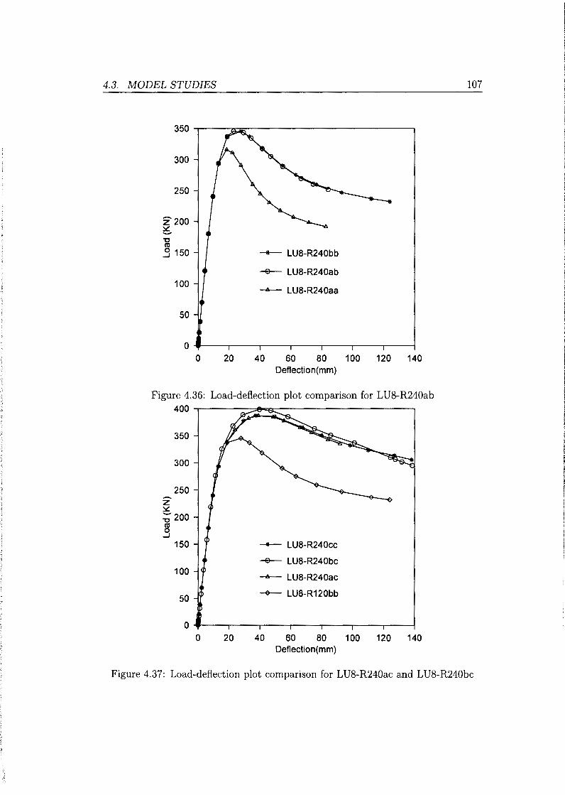
4.3. MODEL STUDIES
300
250
z2oo ~ -"0 ro _g 150
100
50
_.._ LU8-R240bb
-e-- LU8-R240ab
-A-- LU8-R240aa
0 ~---.----.----,----,---,,----.--~ 0 20 40 60 80 100 120 140
Deflection(mm)
Figure 4.36: Load-deflection plot comparison for LU8-R240ab 400 ,-------~~~---------------------.
350
300
250 z ~ :; 200 ro 0
--l
150
100
50
0 0 20
_.._ LU8-R240cc
-e-- LU8-R240bc
-A-- LU8-R240ac
~ LU8-R120bb
40 60 80 Deflection(mm)
100 120 140
107
Figure 4.37: Load-deflection plot comparison for LU8-R240ac and LU8-R240bc

108 CHAPTER 4. NUMERICAL MODEL INVESTIGATION AND RESULTS
4.3.4 Analytical determination of ultimate strength
The analytical approach for hybrid girders closely follows the homogeneous girder
approach. This is justified because as seen from load deflection plots, a hybrid
girder behaves almost like a homogeneous girder with flange steel. It is expected
that the deflections for a hybrid girder are greater at ultimate load, however this is
not evident in the study. Frost and Schilling (1964) assume a perfectly elastic-plastic
material behaviour and this too had an effect on the analytical curve provided.
The quartic equations used in this study were derived for homogeneous girders and
the approximation used for the reference moment Mp ignores the web steel. This was
done to obtain a simpler equation. In the LU8 girder, lateral instability is significant
especially when higher yield steel is used. The moment resistance capacity is reduced
from yield moment My to Mr which is bound by the elastic critical moment. The
analytical ultimate loads obtained before in the analysis of homogeneous girders
are utilised with reduction factors. The reduction factors are based on the steel
combinations in the web and flange and are determined from the relevant equation
2.18 restated below:
R _ 12 + f)(3p- p3)
h- 12+2{3 (4.6)
where 2Dntn Fyw
f)= -A-- and p =smaller of -1
and 1.0 fn n
Atn = sum of the flange area and the area of any cover plates on the side of the
neutral axis corresponding to Dn ( mm2)
Dn = the distance from neutral axis to the inside face of the flange on the side of
the neutral axis where yielding occurs first.
fn =the largest of the specified minimum yield strengths of each component included
in calculation of A fn.
It is stated in the commentary AASHTO (2007) that in most cases Rh is equal to
one. Though the conditions in the AASHTO (2007) regarding ratio of flange steel
grade to web steel are clearly violated for the hybrid girders with 350MPa yield steel
in web and 690MPa yield steel in flange, the reduction factor is used nevertheless.
This is also justified by the fact that this particular steel combination also gave
results that are close to homogenous girders in the load-deflection plots. The results
from the ADINA finite element study show that the ratio of the ultimate load of
a hybrid girder to that of the corresponding homogeneous girder with flange grade
steel is close to one.

4.3. MODEL STUDIES 109
The analytical study gives values of ultimate load for a homogeneous girder scaled
down to the corresponding hybrid girder using Rh. In general, the analytical
approach is rather conservative when a curvature ratio (R/1) of 5 is used for a the
given span lengths. As the ratio R/1 increases, there is a shift showing
increasingly unconservative predictions by equation 2.66 as compared to the finite
element model. The equation 2.67 is also unconservative especially when the ratio
R/1 increases. The difference with finite element model results increase as R/1
increases, thus it is seen that the proposed equations do not converge to the
straight girder case. As R/1 increases, the curvature effects become less
pronounced and the lateral moment reduces. The mode of failure is also
dependant on curvature as it shifts from lateral instability to material yielding
depending on beam slenderness .X.. The results from analytical and computational
methods are summarised in Table 4.9 for comparison.
Table 4.9: Comparison of analytical and finite element ultimate loads for hybrid girders
Beam No Forces Forcey ForceADINA Forces Forcey
ForceADINA ForceADINA (kN) (kN) (kN)
LU5-R25ab 475.8 442.8 694.2 0.69 0.64 LU5-R25ac 668.4 611 850.7 0.79 0.72 LU5-R25bc 688.2 576.2 864.3 0.80 0.67
LU5-R100ab 936.4 902.2 888.0 1.05 1.02 LU5-R100ac 1289.7 1222.1 1051..5 1.23 1.16 LU5-R100bc 1327.9 1089.4 1071.8 1.24 1.02
LU5-R250ab 1163.7 1129.9 1072.5 1.09 1.05 LU5-R250ac 1628.7 1542.3 1216.7 1.34 1.27 LU5-R250bc 1676.9 1355.6 1206.2 1.39 1.12
LU8-R40ab 201.4 17.4 259.2 0.78 0.66 LU8-R40ac 282.8 228.7 318.7 0.89 0.72 LU8-R40bc 291.2 205.2 324.1 0.90 0.63
LU8-R160ab 387.0 321.8 324.4 1.19 0.99 LU8-R160ac 513.9 407.0 372.5 1.38 1.09 LU8-R160bc 529.1 329.3 376.2 1.41 0.88
LU8-R240ab 513.9 413.4 354.9 1.45 1.16 LU8-R240ac 676.5 505.0 397.2 1.70 1.27 LU8-R240bc 696.5 387 398.5 1. 75 0.97
Where FoTce 8 , FoTcey and Fon;eADINA are the ultimate girder forces obtained from equation 2.66, 2.67 and Finite Element Model respectively
The analytical procedure gives results lower than the finite element method for

110 CHAPTER 4. NUMERICAL MODEL INVESTIGATION AND RESULTS
girders LU5-R25 and LU8-R40 which have curvature ratio of 5. Equation 2.67
gives higher values than equation 2.66 for all the girders and also predicts higher
values than the finite element method in all girders except the two given above. At
higher R/1 ratio, the analytical equations overestimate the ultimate load and this
is despite the fac:t that their derivation ignores the small contribution of the web.
The equation by Fukumoto and Nishida (1981) gives the smallest load difference
compared to the finite element method and the equation by Richard et al. (1995) is
generally unconservative.
Results from the computational models from homogeneous and hybrid girders are
compared. The normalised loads for hybrid girders are given with reference to
corresponding homogenous girders. These are shown in Table 4.10 below:
Table 4.10: Comparison of normalised ultimate loads for hybrid girders
Beam No ForceADINA Reference Girder Normalised load (kN)
LU5R25ab 694.2 LU5R25bb 0.98 LU5R25ac 850.7 LC5R25cc 0.97 LU5R25bc 864.3 LU5R25cc 0.98
LU5Rl00ab 888.0 LU5Rl00bb 0.97 LU5R100ac 1051.5 LU5R100cc 0.98 LU5R100bc 1071.8 LU5R100cc 0.99
LU5R250ab 1072.5 LU5R250bb 1.01 LU5R250ac 1216.7 LU5R250cc 1.01 LU5R250bc 1206.2 LU5R250cc 1.00
LU8R40ab 259.2 LU8R40bb 0.98 LU8R40ac 318.7 LC8R40cc 0.96 LU8R40bc 324.1 LU8R40cc 0.98
LU8R120ab 324.4 LU8R120bb 1.01 LU8R120ac 372.5 LU8R120cc 0.99 LU8R120bc 376.2 LU8R120cc 1.00
LU8R240ab 354.9 LU8R240bb 1.03 LU8R240ac 397.2 LU8R240cc 1.03 LU8R240bc 398.5 LU8R240cc 1.03
It is seen from above table that hybrid girders give ultimate loads atleast 97% of
the corresponding homogeneous girders. Such a ratio is consistent with the hybrid
factor Rh previously used in the analytical procedure. This behaviour is expected
since the flanges are the primary load carrying members in girders.

Chapter 5
Conclusion and recommendations
5.1 Conclusion
1. Effect of curvature on ultimate load
Curved hybrid girders have been studied using a verified finite element
procedure. The study covered both hybrid and curvature effects. The
presence of curvature radically modifies a girder's load pattern by causing
additional lateral bending moments. The presence of lateral bending
moments reduces the vertical load carrying capacity of a girder. For the
girder and spans investigated, there is a reduction of 57% in ultimate load
for radius to span ratio (R/L) of 5 compared to a straight girder of similar
proportions and span.The effects of curvature reduce as the arc length to
radius of curvature ratio of a girder is increased.
2. Stress configuration in curved girder
When curvature is introduced, the stress pattern especially in the flange is
altered. This is because the lateral causes the flanges to be unequally stressed.
The inner part of the flange with respect to centre of curvature experiences
higher stresses. Where such stresses are compressive, the inner part will buckle
locally before the outer half.
3. Hybrid configuration
The hybrid configuration considered here had higher strength steel in the
flange and lower strength steel in the web. For all the cases investigated, the
hybrid girders had load deflection plots close to corresponding homogeneous
girders with flange steel grade. The hybrid girders attained at least 97%
of the ultimate load capacity of reference homogeneous girders. The steel

112 CHAPTER 5. CONCLUSION AND RECOMMENDATIONS
combinations used such as 350MPa in web and 690MPa in flange clearly lie
outside the AASHTO (2007) imposed limits.
4. Analysis techniques
From literature, two equations are presented to determine the ultimate load
of homogeneous curved girders. The range of application of these equations
is not known. In the present study, the equation proposed by Fukumoto
and Nishida (1981) generally produces conservative results compared to finite
element model results. The equation proposed by Richard et al. (1995) predicts
loads lower than finite element method for R/L of 5, it is unconservative for
other girders modelled. The finite element model developed was robust enough
as it produced results in agreement with both braced and unbrace girders
previously investigated by Fukumoto and Nishida (1981) and Richard et al.
(1995). In the absence of generally agreed curved beam equations, it remains
the main tool to analyse complex curved beam behaviour.
5.2 Recommendations
1. Range of application for available equations
The ultimate load has been determined using available closed form equations
and finite element analysis. The range of application for the two available
equations should be investigated further. While a wide range for the arc length
to span ratio was investigated, only two spans of 5m and 8m were considered.
2. Hybrid girder moment capacity
The hybrid girders investigated had load-defection behaviour closely
matching that of homogeneous girders. The hybrid girders attained at least
98% of the ultimate load for the reference girders and thus the hybrid factors
predicted are on the safe side. The hybrid factor as proposed by AASHTO
(2007) produces good results and its should be used for the simplified
procedure of approximating hybrid girder loads from homogeneous girder
loads.
3. Curved hybrid girder design
The simpler equation proposed by Fukumoto and Nishida (1981) produces
conservative results and can be used for preliminary design, however other
techniques such as the finite element method should still be used to assess
buckling effects. It is recommended that restrictions on moment redistribution

5.2. RECOMMENDATIONS 113
due to use of high performance steels with yield strength greater that 490MPa
should be investigated further as new HPS are introduced.

Appendices
114

Appendix A
Solution of quartic equation
A.1 Quartic equation derived by Fukumoto and
Nishida (1981)
The solution for ultimate load of a curved girder was implemented using Matlab.
The equation below is solved and the program given.
where .X= !H.; VM:
A.2 Matlab program
% Section and material constants
b=300;
t=16;
d=812;
1=1.2*5000; % Distabilising load condition factor considered.
F=350; % Steel yield stress. Values considered include 460MPa and 690MPa.
R=25000; % The radius is varied according to R/1 ratio.
E=206000;
1=72000000;
G=77000;
J=937000; C=11400000000000;
%Calculation of plastic moment capacity.
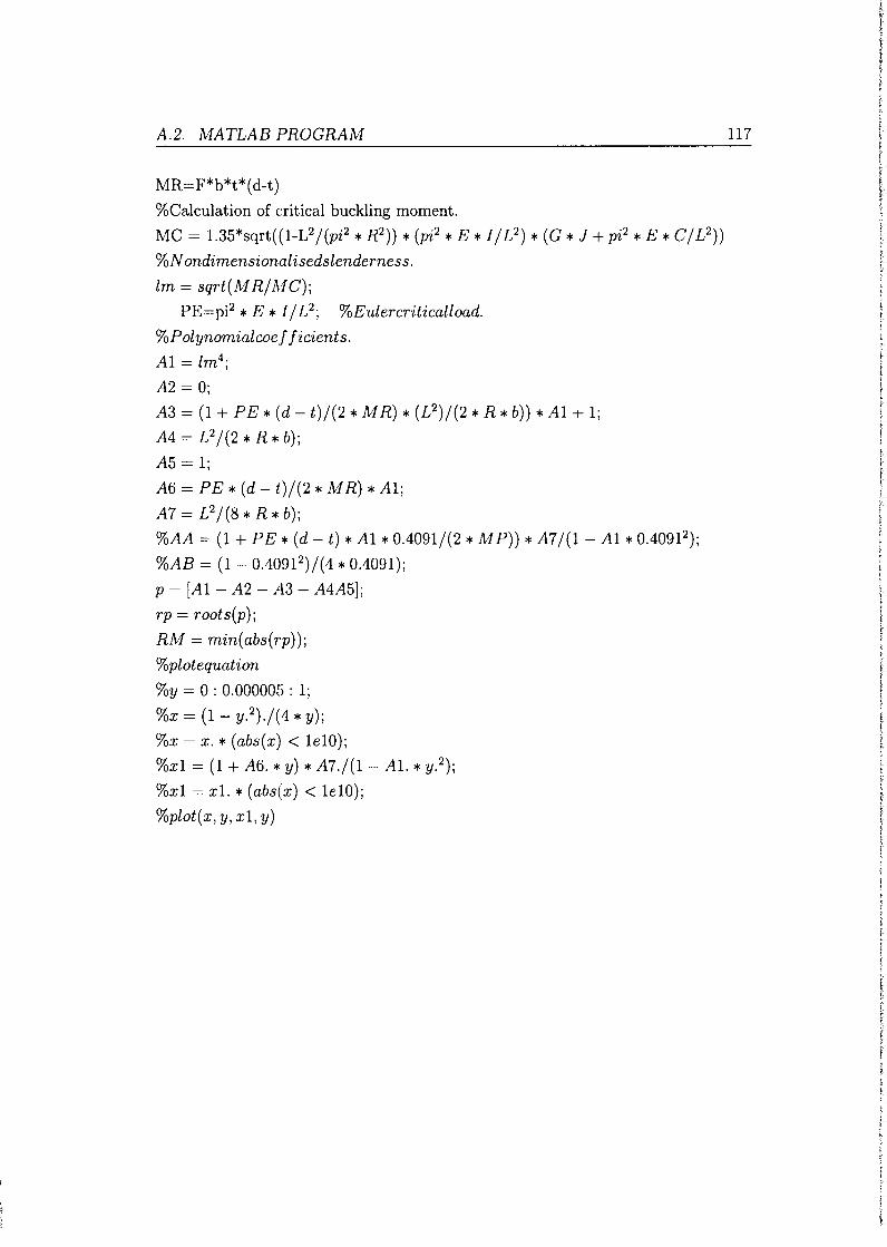
A.2. MATLAB PROGRAM
MR=F*b*t*(d-t)
%Calculation of critical buckling moment.
MC = 1.35*sqrt((1-L2 I(pi2 * R2)) * (pi2 * E *I I L2
) * (G * J + pi2 * E * Cl L2))
%N ondimensionalisedslenderness.
lm = sqrt(MRIMC);
PE=pi2 * E *I I L 2; %E'Ulercr'iticalload.
%Polynomialcoef ficients.
A1 = lm4;
A2 = 0;
A3 = (1 + PE * (d- t)l(2 * M R) * (L2)1(2 * R *b))* A1 + 1;
A4 = L 2 1(2 * R *b);
A5 = 1;
A6 = PE * (d- t)l(2 * M R) * A1;
A7=L2I(8*R*b);
%AA = (1 + PE * (d- t) * A1 * 0.40911(2 * M P)) * A7 1(1- A1 * 0.4091 2);
%AB = (1- 0.40912 )1(4 * 0.4091);
p = [A1- A2- A3- A4A5];
rp = roots(p);
RM = min(abs(rp));
%ploteq'Uation
%y = 0: 0.000005: 1;
%x = (1- y. 2 ).1(4 * y);
%x = x. * (abs(x) < 1e10);
%x1 = (1 + A6. * y) * A7./(1- Al. * y. 2);
%x1 = xl. * (abs(x) < 1e10);
%plot(x, y, x1, y)
117

Appendix B
Solution of quartic equation
B.l Quartic equation presented by Shanmugan
et al. ( 2003)
The solution for ultimate load of a curved girder was implemented using Matlab.
The equation below is solved and the program given.
B.2 Matlab program
%Section and material constants b=300;
t=l6;
d=812;
L=1.2*8000;
% Arc length of 5000 and 8000 used
F=690;

I
B.2. MATLAB PROGRAM
%Yield strength of 350, 460 and 690 used
R=240000;
Radius varies in line with RIL ratio
E=206000;
I= I840000000;
% Major axis IZ==72000000;
% Minor axis G=77000;
J=937000;
C= II400000000000;
%Calculation of plastic moment capacity
M=F*b*t*(d-t);
% Calculation of critical elastic moment capacity
MC=l.35*sqrt((I-L2 l(pi2 * R2)) * (pi2 * E *I I L2
) * (G * J + pi2 * E * Cl L2));
lm = sqrt(M I MC); %nondimensionalisedslenderness
P = pi2 * E *I I L 2; %Eulercr'it'icalload
%Coef ficientsofpolynomial
AI= lm4;
A2 = 0;
119
A3 = (I + p * L 2 * ( d - t) I ( 4 * M * b * R) - ( d - t) * E * I z * L 2 I ( 2 * M * R3 * b) -
2 * PI(M2 * R2) + (P * E *I* L2)1(M2 * R2 * pi2
)) *AI+ I+ 2 * £2l(pi2 * R2);
A 4 = L 2 I ( 2 * R * b) - p * L 2 * A I I ( b * M2 * R3) - L 4 I ( b * R3 * pi2
) + p * E * I *
L4 * AII(2 * M2 * R3 * pi2 *b);
A5
I- 2 * £2 l(pi2 * R2)- 2 * P * AII(R2 * M 2
) + P * E *I* L2 * AII(M2 * R2 * pi2);
%Solution
p = [AI- A2- A3- A4A5];
rp = roots(p)
RM = min(abs(rp))

Appendix C
Hybrid factor AASHTO (2007)
C .1 Hybrid factor
The hybrid factor is used to determine ultimate strength of a hybrid beam by scaling
that of a corresponding homogeneous beam with flange steel grade.
R _ 12 + j3(3p- p3)
h - 12 + 2/3 (C.1)
2Dntn Fyw where /3 =-A--, and p =smaller of -
1 and 1.0,
fn n Afn = sum of the flange area and the area of any cover plates on the side of the
neutral axis corresponding to Dn (mm2 )
Dn = the distance from neutral axis to the inside face of the flange on the side of
the neutral axis where yielding occurs first.
fn = the largest of the specified minimum yield strengths of each component
included in calculation of A fn.
Section and material constants
b=300mm;
t=16mm;
d=812mm;
Thus D = 780mm
Case 1: 460MPa steel in flange 350MPa steel in the web.
= 350
= 0.76087 p 460
j3 = 2 X 390 X 8 = 1.3 300 X 16

)
C.l. HYBRID FACTOR
Rh = 12 + 1.3(3 X 0.76087- 0.760873
) = 0.986 12 + 2 X 1.3
Case 2: 690MPa steel in flange 350MPa steel in the web.
= 350
= 0.5072 p 690
(3 = 2 X 390 X 8 = 1.3 300 X 16
Rh = 12 + 1.3(3 X 0.5072 - 0.50723
) = 0.946 12 + 2 X 1.3
Case 2: 690MPa steel in flange 460MPa steel in the web.
460 p = 690 = 0.667
(3 = 2 X 390 X 8 = 1.3 300 X 16
Rh = 12 + 1.3(3 X 0.667- 0.6673
) = 0.974 12 + 2 X 1.3
121
(C.2)
(C.3)
(C.4)
The commentary to the AASHTO (2007) state that Rh is always close to 1.0

Appendix D
Girder moment capacity: SANS
10162-1
D .1 Yield moment
For section 812*300(8,16), Ze = 4530 x 103mm2 The unfactored capacity for web
flange steel combinations:
aa: Zefy = 1585.5kNm
bb: Zefy = 2083.8kNm
cc: Zefy = 3125.7kNm
For the 5m and 8 m simply supported straight girders with a distabilising load
the critical moment is obtained SAISC (2008):
5m girder: Mer == 1660kN m
8m girder: Mer== 613kNm
Moment capacity is given as before:
(i) when Mer > 0.67 My
( 0.28My)
Mr = 1.15¢My 1 - Mer but not greater than ¢My
(ii) when Mer ~ 0.67 My
where:
Mer is elastic buckling moment given in equation 2.3

D.l. YIELD MOMENT
My is the moment resistance capacity given as My = </JZyfy
Ze is elastic section modulus
JY is the steel yield strength.
<P = 1, no factors applied.
Thus for 5m girder, the moment resistance is given:
aa: Mr = 1335.7kNm
bb: Mr = 1554.1kN m
cc: Mr = 1660kN m
Thus for 8m girder Mer ::; 0.67 Mp, thus moment resistance is given:
aa: Mr = 613.3kNm
bb: Mr = 613.3kNm
cc: Mr = 613.3kNm
123
The load at the mid span is obtained: P = 4~r where Lis the span: 5m girder:
aa: Mr = 1068.6kNm
bb: Mr = 1243.3kN m
cc: Mr = 1328.0kNm
8m girder:
aa: Mr = 349kN m
bb: Mr = 349kN m
cc: Mr = 349kN m

References
AASHTO, LRFD Bridge Design Specifications, American Association of State
Highway and Transportation Officials, Washington, D.C, 2007.
Abdel-Sayed G., "Curved webs under combined shear and normal stresses," Journal
of the Structural Division ASCE, Vol 99 No.ST3; 511-525, March 1973.
ASCE, "Curved !-Girder bridge Design Recommendations," Journal of Structural
Engineering ASCE, Vol103 ST5; 1137-1396, May 1977.
ASCE W.R.C., Plastic design in Steel, a guide and commentary, 2Ed, ASCE, New
York, (1971).
ASCE-AASHO, "Design of Hybrid Steel Beams," Journal of Structural Engineering
ASCE, ST6; 1397-1426, 1968.
Azizinamini A., Barth K., Dexter R. and Reubeiz C., "High Performance Steel:
Research Front-Historical Account of Research Activities," Journal of Bridge
Engineering ASCE, Vol 9 No3; 212-217, May 2004.
Barth K.E., Righman J.E. and Freeman L.B., "Assessment of AASHTO LRFD
Specification for Hybrid HPS 690W Steel !-Girders," Journal of Bridge
Engineering, Vol 12; 380-388, 2007.
Basler K. and Thurlimann B., "Strength of plate girders in bending," Journal of the
Structural Division ASCE, Vol 87 No.ST6; 153-181, August 1961.
Bathe K.J., Finite Element Procedures 1 Ed, Prentice-Hall, Inc. New Jersey, (1996).
Benham P., Crawford R.J. and Armstrong C., Mechanics of Engineering Materials
2nd ed, Pearsod Ed Limited Harlow, England, (1996).
Bjorhivde R., ·'Development and use of high performance steel," Journal of
Construction Steel Research, Vol 60; 393-400, 2004.

REFERENCES 125
Boresi A.P. and Chong K.P., Elasticity in Engineering Mechanics 2nd ed, John
Wiley & Sons inc, New York, (1996).
Carskaddan P.S., "Shear buckling of unstiffened hybrid beams," Journal of
Structural Engineering ASCE, Vol 94 ST8; 1965-1991, August 1968.
Chung W. and Sotelino E.D., "Three-dimensional finite element modeling of
composite girder bridges," Engineering Structures, Vol 28; 63-71, 2006.
Culver C.G. and Frampton R.E., "Local instability of horizontally curved members,"
Journal of Structural Division, ASCE, Vol 96 No ST2; 245-265, Feb 1970.
Davidson J., Ballance S.R. and Yoo C.H., "Evaluation of Strength formulations
for horizontally curved flexural members," Journal of Bridge Engineering ASCE,
Vol5 No3; 20G-207, August 2000b.
Davidson J., Ballance S.R. and Yoo C.H., "Behaviour of curved !-girder webs
subjected to combined bending and shear," Journal of Bridge Engineering ASCE,
Vol5 No2; 165--178, May 2000a.
Davidson J.S., Ballance S.R. and Yoo C.H., "Finite displacement behaviour of
curved !-girder webs subject to bending," Journal of Bridge Engineering ASCE,
Vol 4 No3; 213-220, August 1999.
Davidson J.S., Keller M.A. and Yoo C.H., "Cross-frame spacing and parametric
effects in horizontally curved !-girder bridges," Journal of Structural Engineering
ASCE, Vol 122, No9; 1089-1096, 1996.
Davidson J.S. and Yoo C.H., "Local buckling of curved !-girders," Journal of
Structural Engineering ASCE, Vol 122, NoS; 938-948, 1996.
Earls C., "On the inelastic failure of high strength steel !-shaped beams," Journal
of Construction Steel Research, Vol 49; 1-24, 1999.
EN1993-1-1 E., "Eurocode EN 1993-1-1," .
Frost R.W. and Schilling C.G., "Behaviour of hybrid beams subjected to static
loads," Journal of Structural Division, ASCE, Vol 90 No ST3; 55-87, June 1964.
Fukumoto Y. and Nishida S., "Ultimate Load Behaviour of Curved !-Beams,"
Journal of Engineering Mechanics ASCE, Vol 107 No.EM2; 367-385, April 1981.
126 REFERENCES
Galambos T.V. (ed.), Guide to Stability Design Criteria for Metal Structures SEd,
John Wiley and Sons Inc, New York, (1998).
Gunther H.P. (ed.), Use and Application of High-Performance Steels for Steel
Structures, IABSE-AIPC-IVBH, Zirich, (2005).
Haaijer G., "Economy of high strength steel structural members," Journal of the
Structural Division Proc of ASCE, ST 8; 1-23, 1961.
Hall D.H., "Curved girders are special," Engineering Structures, 18-10; 769-777,
1996.
Heins C., Bending and Torsional Design in Structural Members, D.C. Heath and
Company, Massachusetts, (1975).
Ito M., Nozaka K., Shirosaki T. and Yamasaki K., "Experimental Study on Moment
Plastic Rotation Capacity of Hybrid Beams," Journal of Bridge Engineering
ASCE, Vol 10 No 4; 490-496, 2005.
Jung S.K. and W.White D., "Shear strength of horizontally curved steel !-girders
finite element analysis studies," Journal of Construction Steel Research, Vol 62;
329-342, 2006.
Kang Y.J. and Yoo C.H., "Thin-walled curved beams 1: Analytical solution for
buckling of arches," Journal of the Structural Engineering ASCE, Vol 120 No.lO;
2072-2099, October 1994a.
Kang Y.J. and Yoo C.H., "Thin-walled curved beams II: Analytical solution for
buckling of arches," Journal of the Structural Engineering ASCE, Vol 120 No.10;
2102-2125, October 1994b.
Lee S., Davidson J. and Yoo C., "Shear buckling coefficients of plate girder web
panels," Computers and structures, Vol 59 No.5; 789-795, 1996.
Lee S.C. and Yoo C.H., "Strength of plate girder web panels under pure shear,"
Journal of Structural Engineering ASCE, Vol 124 No2; 184-194, 1998.
Lee S.C. and Yoo C.H., "Experimental study on ultimate shear strength of web
panels," Journal of Structural Engineering ASCE, Vol 125 No.8; 838-846, 1999a.
Lee S.C. and Yoo C.H., "Strength of curved 1- girder web panels under pure shear,"
Journal of Structural Engineering ASCE, Vol 125 No.8; 847-853, 1999b.

REFERENCES 127
Linzell D., Hall D. and White D., "Historical Perspective on Horizontal Curved I
Girder Bridge Design in the United States," Journal of Bridge Engineering ASCE,
Vol 9 No 3; 218-229, May 2004.
Miki C., Homma K. and Tominaga T., "High strength and high performance steels
and their use in bridge structures," Journal of Construction Steel Research, Vol
58; 3-20, 2002.
Murray D.W. and Rajasekaran S., "Technique for formulating beam equations,"
Journal of Engineering Mechanics ASCE, Vol 101 EMC5; 561-572, 1975.
NCHRP-Report-563, Development of LRFD Specifications for Horizontally Curved
Steel Girder B1·idges, 2006.
Paik J.K. and Thayamballi A.K., Ultimate Limit State Design of Steel-Plated
Structures, 1st Ed, John Wiley & Sons Ltd, England, (2003).
Papangelis J. and Trahair N., "Flexural-Torsional Buckling of Arches," Journal of
the Structural Engineering ASCE, Vol 113 No.4; 889-906, April 1987.
Pi Y.L. and Bradford M.A., "Strength design of steel !-section beams curved in
plan," Journal of Structural Engineering ASCE, Vol 127 No6; 639-646, June
2001.
Rajasekaran and Ramm E., "Flexural-Torsional Stability of Curved Beams
Discussion," Journal of Structural Engineering ASCE, Vol No; 144-149, December
1982.
Richard J.Y., Thevendran L.V., Shanmugan N.E. and Tan L., "Behaviour and
Design of Horizontally Curved Steel Beams," Journal of Construction Steel
Research, Vol 37; 37-67, 1995.
SAISC, Southern African Steel Construction Handbook, 6Ed, SAISC, Johannesburg,
(2008).
Saje M., Turk G., Kalagasidu A. and Vratanar B., "A Kinematically exact finite
element formulation of elastic-plastic curved beams," Computers and Structures,
Vol 67; 197-214, 1998.
Salmon C.G. and Johnson J.E., Steel Structures-Design and Behaviour, 4th Ed,
Prentice Hall,Inc. New Jersey, (1996).

128 REFERENCES
Sause R. and Fahnestock L., "Strength and ductility of HPS-lOOW !-Girders in
negative flexure," Journal of Bridge Engineering ASCE, Vol 6 No5; 316-323,
October 2001.
Schilling C.G., "Yield-Interaction Relationships for Curved !-Girders," Journal of
Bridge Engineering, Vol 1; 26-33, 1996.
Schilling C.G., ''Web criplling tests on hybrid beams," Journal of Structural
Engineering, Vol 93 STl; 59-71, Feb 1967.
Schilling C.G., "Moment Rotation Tests of Steel Bridge Girders," Journal of
Structural Engineering, Vol 114 No.1; 134-149, January 1988.
Shanmugan N.E., Mahendrakumar M. and Thevendran V., "Ultimate load
behaviour of horizontally curved plate girders," Journal of Construction Steel
Research, Vol 59; 510-529, 2003.
Shanmugan N.E., Thevendran V., Liew J.R. and Tan L., "Experimental study on
steel beams curved in plan," Journal of Structural Engineering, Vol 121 No2;
249-259, Feb 1995.
Tall L., Structural steel design 2nd Ed, The Ronald Press Company, New York,
(1974).
Timoshenko G., Theory of Elastic Stability 2nd Ed, McGraw-Hill Book Company,
Inc, (1961).
Trahair N. and Bradford M., The Behaviour and Design of Steel Structures,
Chapman and Hall, London, (1988).
Ugural A. and Fenster S.K., Advanced Strength and applied Elasticity, 1st Ed,
Edward Anold Publisher, London, (1981).
Vacharajittiphan P. and Trahair N ., "Flexural-Torsional Buckling of Curved
Members," Journal of the Structural Division ASCE, VollOl No.ST6; 1223-1238,
June 1975.
Veljkovic M. and Johansson B., "Design of hybrid steel girders," Journal of
Construction Steel Research, Vol 60; 535-547, 2004.
Vlasov V., Thin Walled Elastic Beams, 2nd Ed, Israel Program for Scientific
Translations, Jerusalem, (1961).

REFERENCES 129
White D.W. and Barth K., "Strength and Ductility of Compact-Flange !-Girders in
Negative Bending," Journal of Construction Steel Research, Vol45 No 3; 241-280,
1998.
Wollman G.P., "Steel Girder Design per AASHTO LRFD Specifications (Part 1),"
Journal of Bridge Engineering, Vol 9; 364-374, 2004.
Yang Y.B. and Kuo S.R., "Static Stability of Curved Thin-Walled Beams," Journal
of Engineering Mechanics ASCE, Vol 112 NoS; 821-841, August 1986.
Yang Y.B. and Kuo S.R., "Effect of Curvature on Stability of Curved Beams,"
Journal of Structural Engineering ASCE, Vol 113 No6; 1185-1202, June 1987.
Yoo C.H., "Flexural Torsional Stability of Curved Beams," Journal of Engineering
Mechanics Division ASCE, Vol 108 No.EM6; 1351-1369, Dec 1982.
Yoo C.H. and Davidson J.S., "Yield-interaction relationships for nominal bending
strength of curved !-girders," Journal of bridge engineering ASCE, Vol 2 No.2;
37-44, 1997.
Yoo C.H. and Heins C.P., "Plastic Collapse of Horizontally Curved Bridge Girders,"
Journal of Structural Division ASCE, Vol 98 No.ST4; 899-914, April 1972.
Zureick A., Linzel D. and R. T Leon J.B., "Curved steel !-girder bridges:
experimental and analytical studies," Engineering Structures, Vol 22; 180-190,
2000.


![Distortional analysis of simply supported box girders with ......lar conclusions can be drawn for straight multi-cell box girders with diaphragms [18,19]. For horizontally curved bridges,](https://static.fdocuments.in/doc/165x107/6145e3178f9ff812541fe9b9/distortional-analysis-of-simply-supported-box-girders-with-lar-conclusions.jpg)