Stability of Long Span Steel Bridges During Design and ...AASHTO Standard Specifications for Highway...
55
Stability of Long Span Steel Bridges During Design and Construction Presented by: Kevin D. Sear, P.E. (AECOM) Robert A. Cisneros, P.E. (High Steel Structures)
Transcript of Stability of Long Span Steel Bridges During Design and ...AASHTO Standard Specifications for Highway...
Stability of Long Span Steel Bridges During Design
and Construction
Presented by: Kevin D. Sear, P.E. (AECOM)Robert A. Cisneros, P.E. (High Steel Structures)
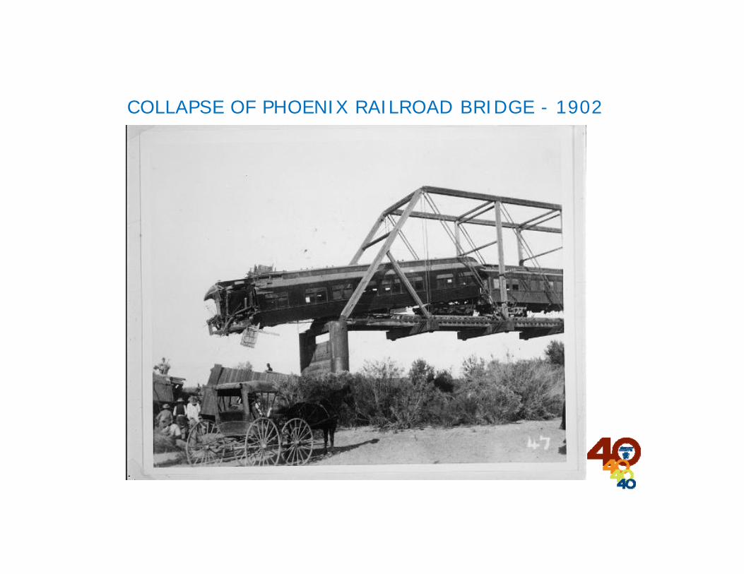
COLLAPSE OF PHOENIX RAILROAD BRIDGE - 1902
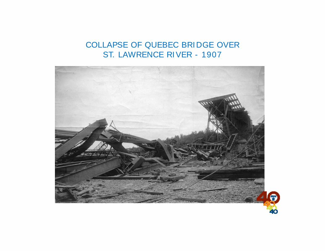
COLLAPSE OF QUEBEC BRIDGE OVER ST. LAWRENCE RIVER - 1907
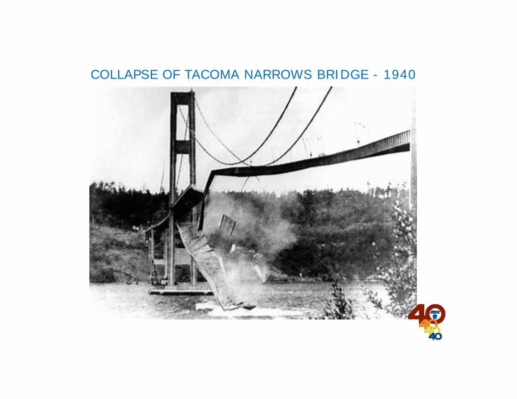
COLLAPSE OF TACOMA NARROWS BRIDGE - 1940
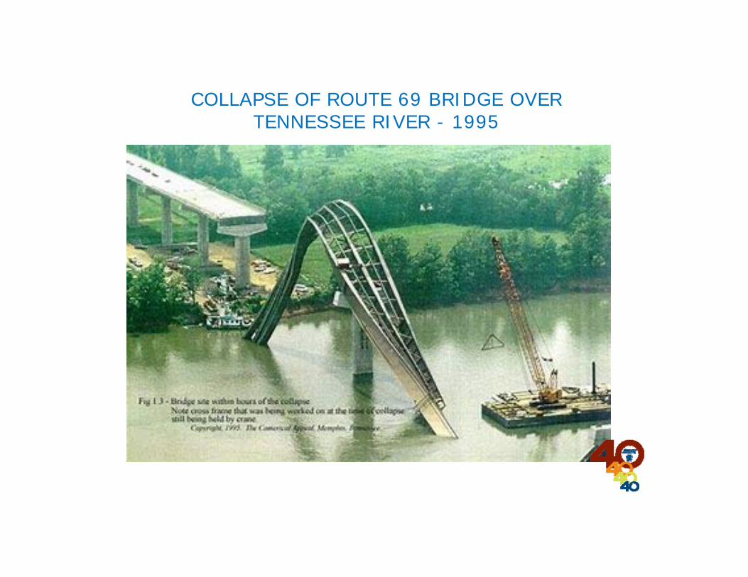
COLLAPSE OF ROUTE 69 BRIDGE OVER TENNESSEE RIVER - 1995

STABILITY
As defined by the Merriam-Webster dictionary is“the property of a body that causes it whendisturbed from a condition of equilibrium orsteady motion to develop forces or moments thatrestore the original condition”
Another, more bridge specific definition is the lackof undesirable deflections or rotations.
STRENGTH
As defined by the Merriam-Webster dictionary is“the quality or state of being strong : capacity forexertion or endurance”
Another, more bridge specific definition is the lackof undesirable member stresses.

ECONOMICAL STRUCTURAL DESIGNThe goal is to determine a system where stability isprovided using members that require the leastamount of material above that needed to meetstrength requirements.
INSTABILITYCan occur at various stages during the life of a longspan steel girder bridge.Completed Bridge (Responsibility of Designer)Deck Placement (Responsibility of Designer)Completed Framing (Responsibility of Designer)Girder Erection (Responsibility of Erector)

APC FALL SEMINAR
PART I
STABILITY OF LONG SPAN BRIDGES DURING DESIGN
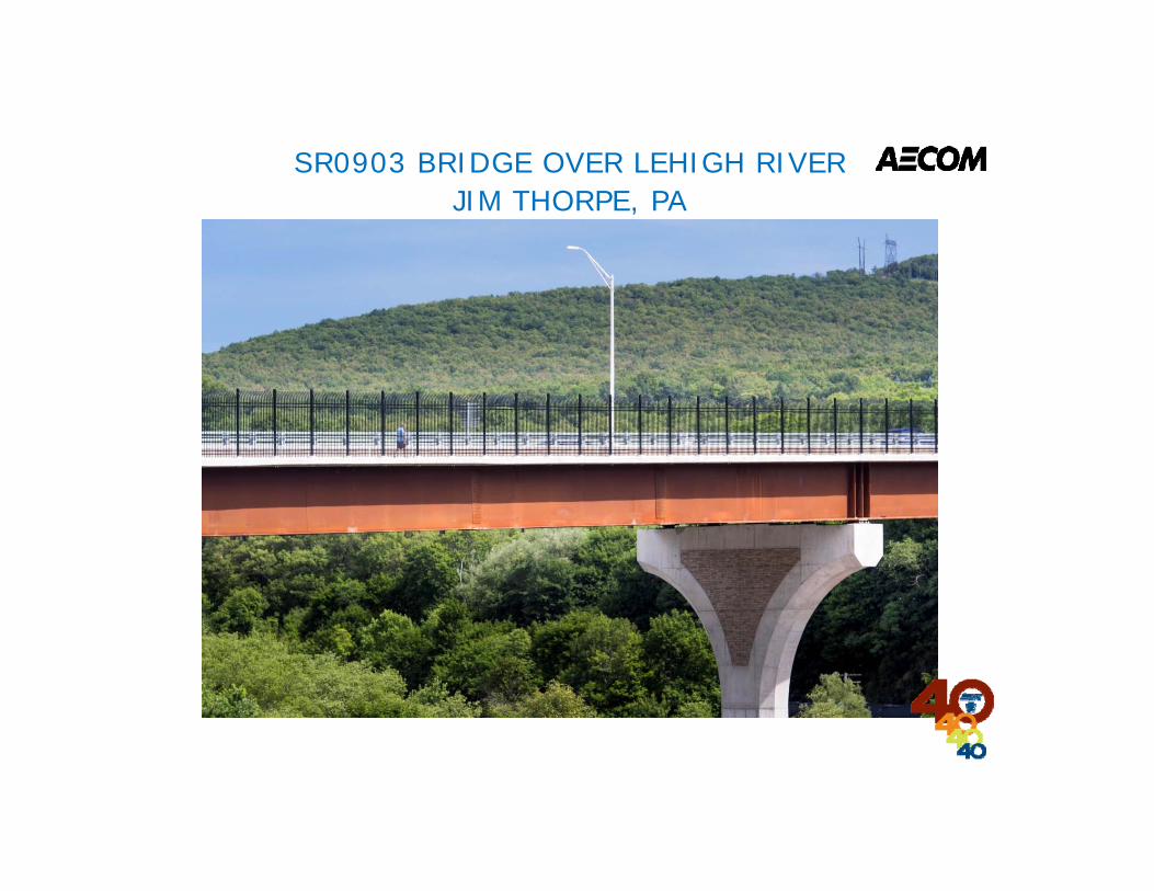
SR0903 BRIDGE OVER LEHIGH RIVERJIM THORPE, PA
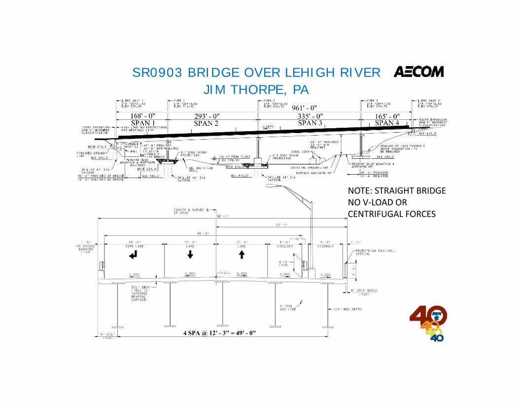
SR0903 BRIDGE OVER LEHIGH RIVERJIM THORPE, PA
NOTE: STRAIGHT BRIDGENO V‐LOAD OR CENTRIFUGAL FORCES
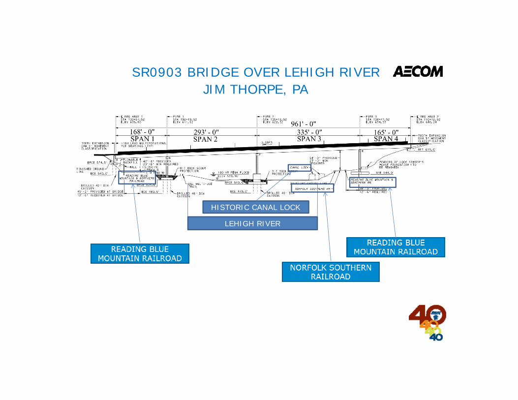
SR0903 BRIDGE OVER LEHIGH RIVERJIM THORPE, PA
LEHIGH RIVER
HISTORIC CANAL LOCK

COMPLETED BRIDGE STAGE
CONCRETE DECK
CROSS FRAMESCONNECTION PLATES
SR0903 BRIDGE OVER LEHIGH RIVERJIM THORPE, PA

COMPLETED BRIDGE STAGE
SR0903 BRIDGE OVER LEHIGH RIVERJIM THORPE, PA
WHERE STRESS CAPACITY WAS LESS THAN YIELD USING 25’ CROSS FRAME SPACING, CAPACITY WAS INCREASED BY REDUCING CROSS FRAME SPACING TO ABOUT 16.5’.(BOTTOM FLANGE IN COMPRESSION – NEGATIVE MOMENT)
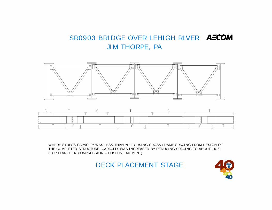
DECK PLACEMENT STAGE
SR0903 BRIDGE OVER LEHIGH RIVERJIM THORPE, PA
WHERE STRESS CAPACITY WAS LESS THAN YIELD USING CROSS FRAME SPACING FROM DESIGN OF THE COMPLETED STRUCTURE, CAPACITY WAS INCREASED BY REDUCING SPACING TO ABOUT 16.5’.(TOP FLANGE IN COMPRESSION – POSITIVE MOMENT)
COMPLETED FRAMING STAGE
SR0903 BRIDGE OVER LEHIGH RIVERJIM THORPE, PA
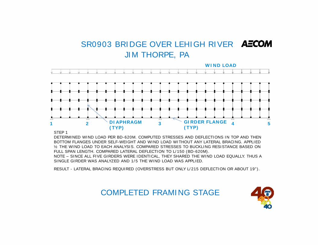
WIND LOAD
DIAPHRAGM (TYP)
1 2 3 4 5GIRDER FLANGE (TYP)
STEP 1DETERMINED WIND LOAD PER BD-620M. COMPUTED STRESSES AND DEFLECTIONS IN TOP AND THEN BOTTOM FLANGES UNDER SELF-WEIGHT AND WIND LOAD WITHOUT ANY LATERAL BRACING. APPLIED ½ THE WIND LOAD TO EACH ANALYSIS. COMPARED STRESSES TO BUCKLING RESISTANCE BASED ON FULL SPAN LENGTH. COMPARED LATERAL DEFLECTION TO L/150 (BD-620M).NOTE – SINCE ALL FIVE GIRDERS WERE IDENTICAL, THEY SHARED THE WIND LOAD EQUALLY. THUS A SINGLE GIRDER WAS ANALYZED AND 1/5 THE WIND LOAD WAS APPLIED.
RESULT - LATERAL BRACING REQUIRED (OVERSTRESS BUT ONLY L/215 DEFLECTION OR ABOUT 19”).
COMPLETED FRAMING STAGE
SR0903 BRIDGE OVER LEHIGH RIVERJIM THORPE, PA
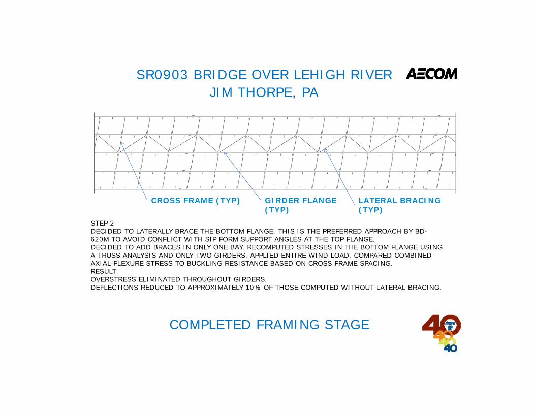
STEP 2DECIDED TO LATERALLY BRACE THE BOTTOM FLANGE. THIS IS THE PREFERRED APPROACH BY BD-620M TO AVOID CONFLICT WITH SIP FORM SUPPORT ANGLES AT THE TOP FLANGE.DECIDED TO ADD BRACES IN ONLY ONE BAY. RECOMPUTED STRESSES IN THE BOTTOM FLANGE USING A TRUSS ANALYSIS AND ONLY TWO GIRDERS. APPLIED ENTIRE WIND LOAD. COMPARED COMBINED AXIAL-FLEXURE STRESS TO BUCKLING RESISTANCE BASED ON CROSS FRAME SPACING.RESULTOVERSTRESS ELIMINATED THROUGHOUT GIRDERS.DEFLECTIONS REDUCED TO APPROXIMATELY 10% OF THOSE COMPUTED WITHOUT LATERAL BRACING.
CROSS FRAME (TYP) LATERAL BRACING (TYP)
GIRDER FLANGE (TYP)
COMPLETED FRAMING STAGE
SR0903 BRIDGE OVER LEHIGH RIVERJIM THORPE, PA
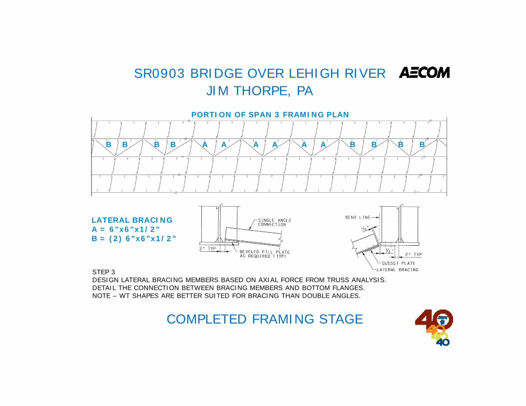
STEP 3DESIGN LATERAL BRACING MEMBERS BASED ON AXIAL FORCE FROM TRUSS ANALYSIS.DETAIL THE CONNECTION BETWEEN BRACING MEMBERS AND BOTTOM FLANGES.NOTE – WT SHAPES ARE BETTER SUITED FOR BRACING THAN DOUBLE ANGLES.
LATERAL BRACINGA = 6”x6”x1/2”B = (2) 6”x6”x1/2”
B B B B A A A A A A B B B B
PORTION OF SPAN 3 FRAMING PLAN

PART I ASSESSMENT
Question: True or False, The goal of economical structural designs is to determine a system where stability requires more material than that needed to meet strength requirements.
A – TrueB – False
PART I ASSESSMENT
Question: True or False, The goal of economical structural designs is to determine a system where stability requires more material than that needed to meet strength requirements.
A – TrueB – False
Answer: False – The goal is to NOT require more material for stability than for strength.
QUESTIONS
APC FALL SEMINAR
PART II
STABILITY OF LONG SPAN BRIDGES DURING ERECTION

REFERENCES:1. PADOT BD 620M (which Kevin has discussed)2. NHI Course3. AASHTO/NSBA S10.1‐2014 Steel Bridge Erection Guide Specification
https://www.nhi.fhwa.dot.gov/downloads/catalog/FHWA‐NHI‐130102.pdf
"Those who don't know history are destined to repeat it." Santayana/Burke
WAYPOINTS
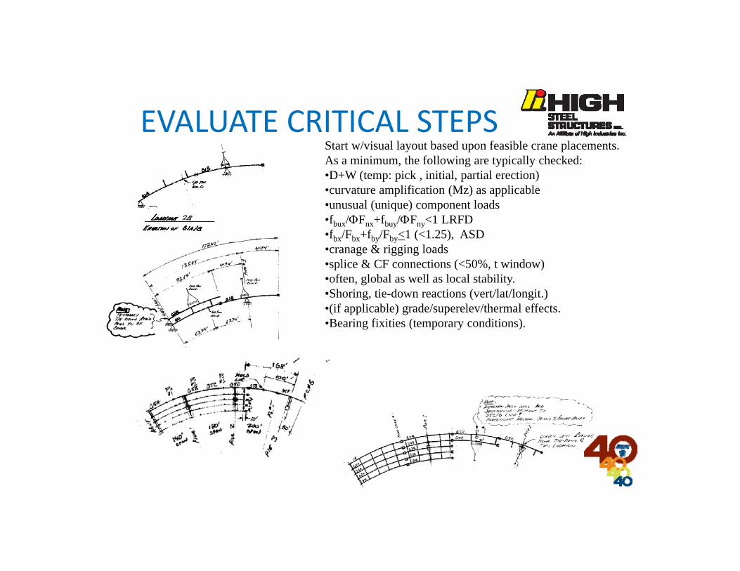
EVALUATE CRITICAL STEPSStart w/visual layout based upon feasible crane placements. As a minimum, the following are typically checked:•D+W (temp: pick , initial, partial erection)•curvature amplification (Mz) as applicable•unusual (unique) component loads•fbux/Fnx+fbuy/Fny<1 LRFD•fbx/Fbx+fby/Fby<1 (<1.25), ASD•cranage & rigging loads•splice & CF connections (<50%, t window)•often, global as well as local stability.•Shoring, tie-down reactions (vert/lat/longit.)•(if applicable) grade/superelev/thermal effects.•Bearing fixities (temporary conditions).
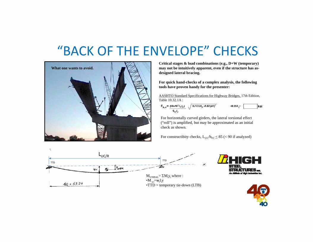
Critical stages & load combinations (e.g., D+W (temporary) may not be intuitively apparent, even if the structure has as-designed lateral bracing.
For quick hand-checks of a complex analysis, the following tools have proven handy for the presenter:
AASHTO Standard Specifications for Highway Bridges, 17th Edition, Table 10.32.1A :
For horizontally curved girders, the lateral torsional effect (“roll”) is amplified, but may be approximated as an initial check as shown.
For constructibity checks, LUC/bFC < 85 (< 90 if analyzed)
What one wants to avoid.
“BACK OF THE ENVELOPE” CHECKS
MUNBAL= Miyi where :•M y,i=wiliy•TTD = temporary tie-down (LTB)
LUC/RTTD
TTD
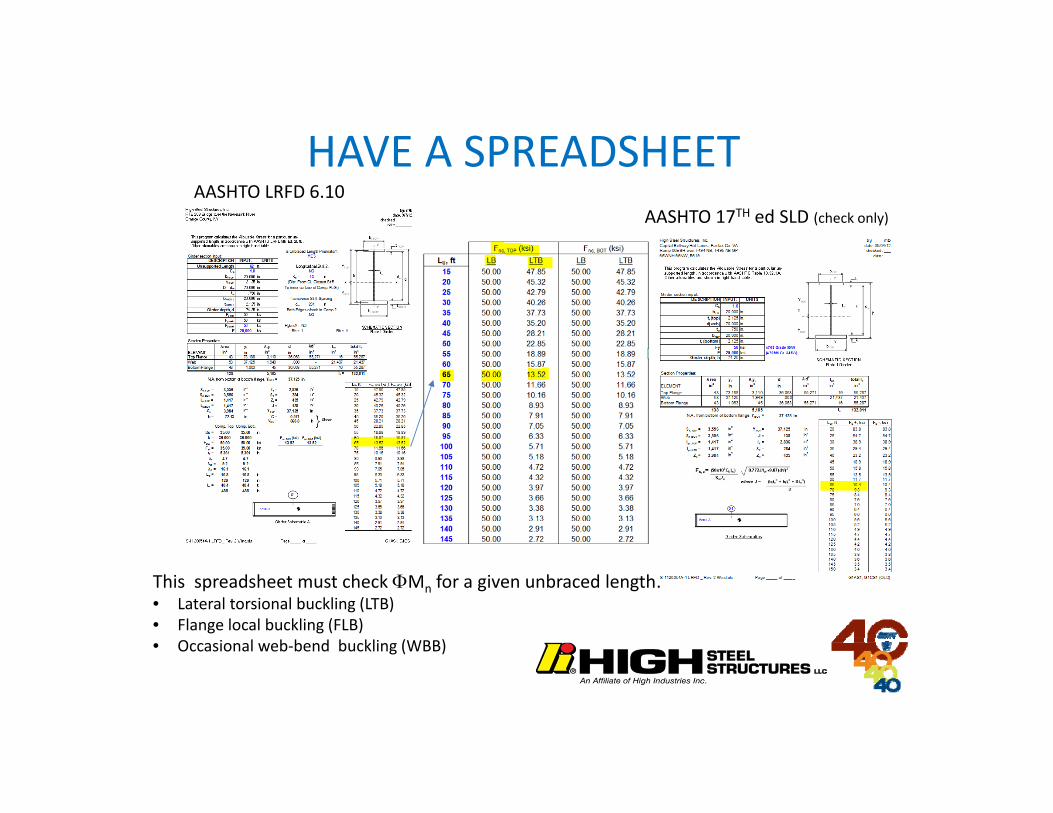
HAVE A SPREADSHEET
This spreadsheet must check Mn for a given unbraced length:• Lateral torsional buckling (LTB)• Flange local buckling (FLB)• Occasional web‐bend buckling (WBB)
AASHTO LRFD 6.10AASHTO 17TH ed SLD (check only)
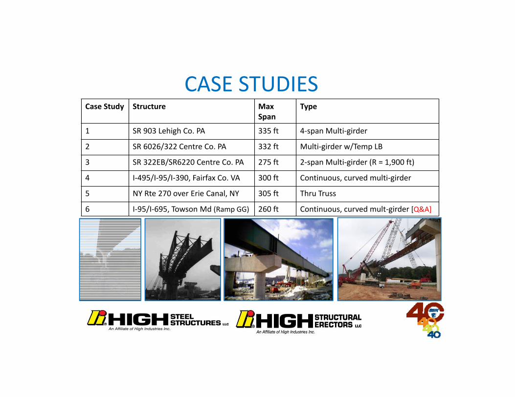
CASE STUDIESCase Study Structure Max
SpanType
1 SR 903 Lehigh Co. PA 335 ft 4‐span Multi‐girder
2 SR 6026/322 Centre Co. PA 332 ft Multi‐girder w/Temp LB
3 SR 322EB/SR6220 Centre Co. PA 275 ft 2‐span Multi‐girder (R = 1,900 ft)
4 I‐495/I‐95/I‐390, Fairfax Co. VA 300 ft Continuous, curved multi‐girder
5 NY Rte 270 over Erie Canal, NY 305 ft Thru Truss
6 I‐95/I‐695, Towson Md (Ramp GG) 260 ft Continuous, curved mult‐girder [Q&A]

CASE STUDY I: JIM THORPE, PA

LB OPTION USED
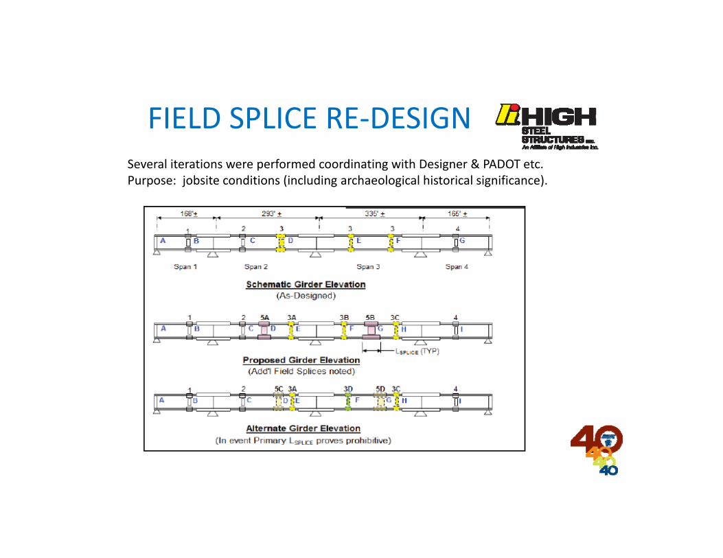
Several iterations were performed coordinating with Designer & PADOT etc.Purpose: jobsite conditions (including archaeological historical significance).
FIELD SPLICE RE‐DESIGN
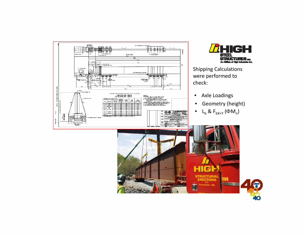
Shipping Calculations were performed to check:
• Axle Loadings• Geometry (height)• Lb & FbX+Y (Mn)

Erection Stability analysis was performed to check:
• Crane capacities (picks)• Lb & FbX+Y (Mn)• UT Bridge validation of STAAD

CASE STUDY II: CENTRE CO. PA
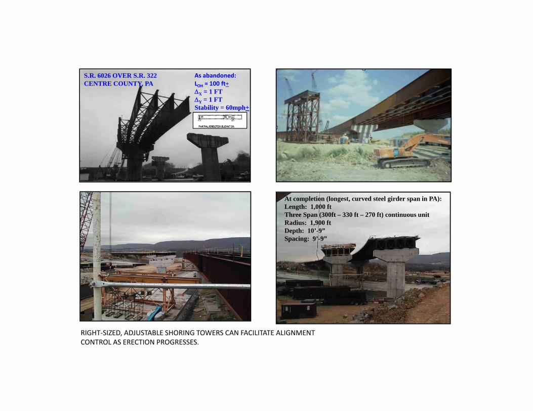
At completion (longest, curved steel girder span in PA):Length: 1,000 ftThree Span (300ft – 330 ft – 270 ft) continuous unitRadius: 1,900 ftDepth: 10’-9”Spacing: 9’-9”
As abandoned:LOH = 100 ft+X = 1 FTY = 1 FTStability = 60mph+
RIGHT‐SIZED, ADJUSTABLE SHORING TOWERS CAN FACILITATE ALIGNMENT CONTROL AS ERECTION PROGRESSES.
S.R. 6026 OVER S.R. 322 CENTRE COUNTY, PA

INITIAL STABILIZATION
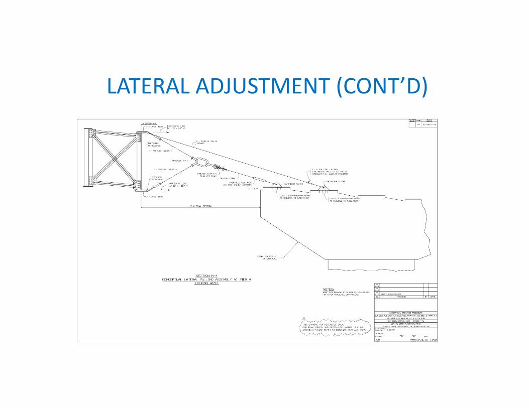
LATERAL ADJUSTMENT (CONT’D)

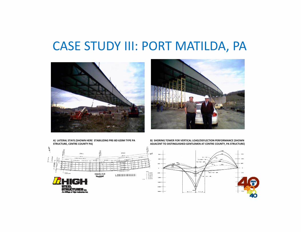
B) SHORING TOWER FOR VERTICAL LOAD/DEFLECTION PERFORMANCE (SHOWN ADJACENT TO DISTINGUISHED GENTLEMEN AT CENTRE COUNTY, PA STRUCTURE)
A) LATERAL STAYS (SHOWN HERE STABILIZING PRE‐BD 620M TYPE PA STRUCTURE, CENTRE COUNTY PA)
CASE STUDY III: PORT MATILDA, PA
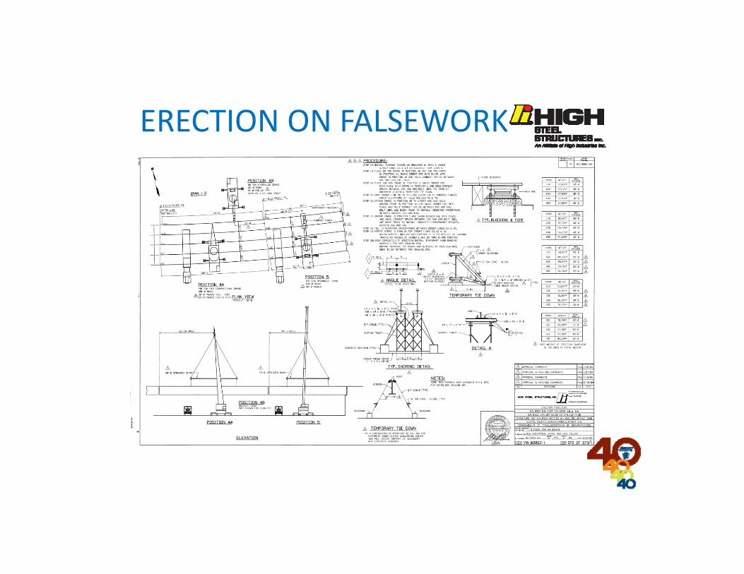
ERECTION ON FALSEWORK
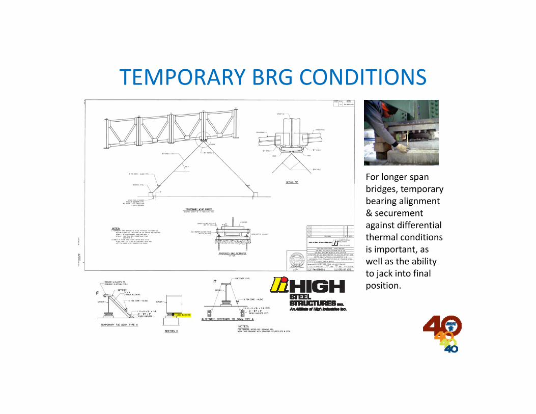
TEMPORARY BRG CONDITIONS
For longer span bridges, temporary bearing alignment & securement against differential thermal conditions is important, as well as the ability to jack into final position.
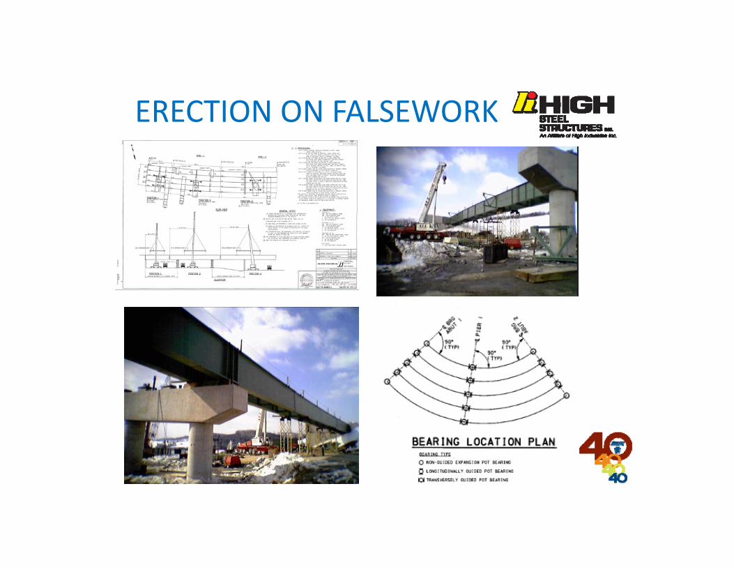
ERECTION ON FALSEWORK
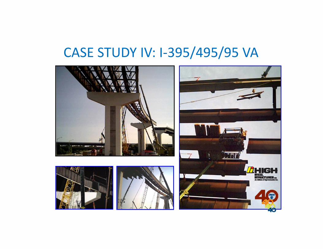
CASE STUDY IV: I‐395/495/95 VA
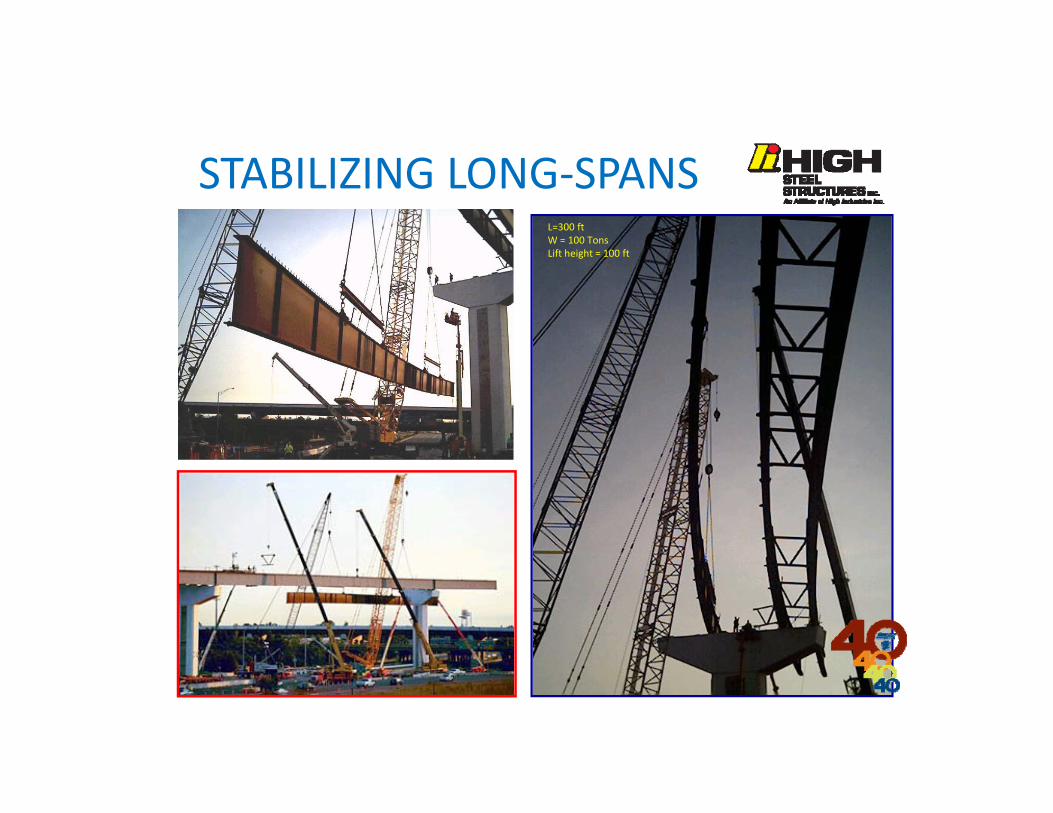
STABILIZING LONG‐SPANSL=300 ftW = 100 TonsLift height = 100 ft
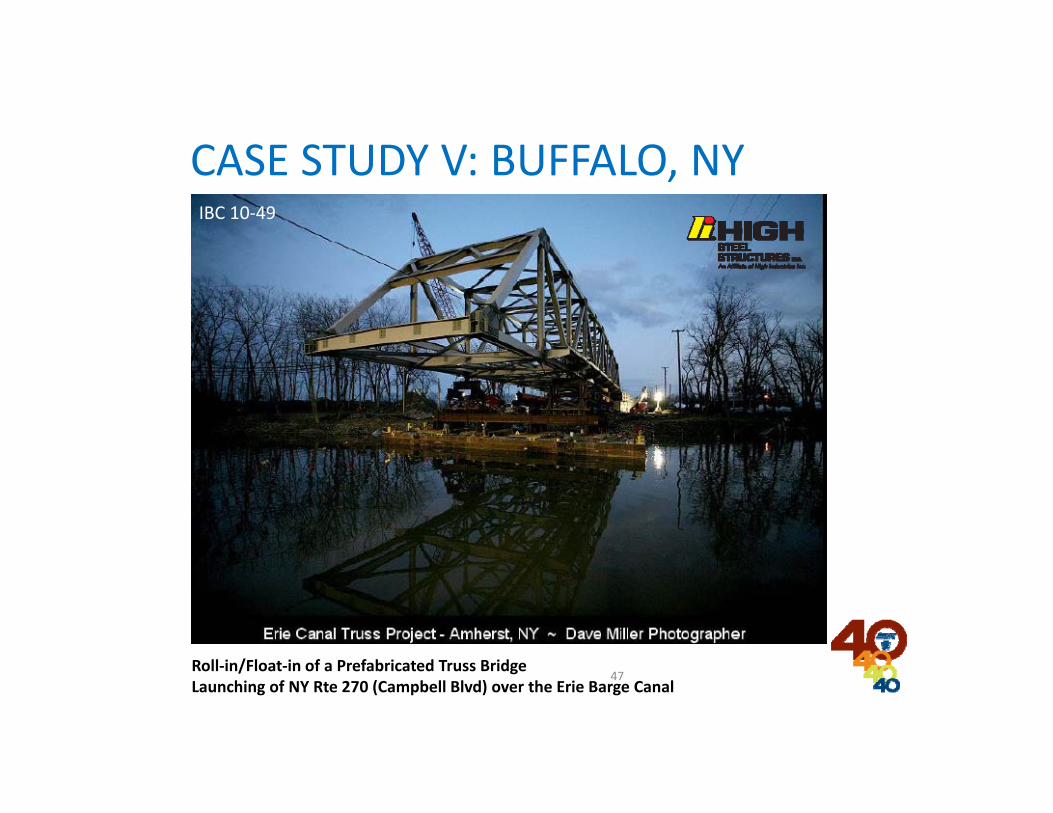
47Roll‐in/Float‐in of a Prefabricated Truss BridgeLaunching of NY Rte 270 (Campbell Blvd) over the Erie Barge Canal
IBC 10‐49
CASE STUDY V: BUFFALO, NY
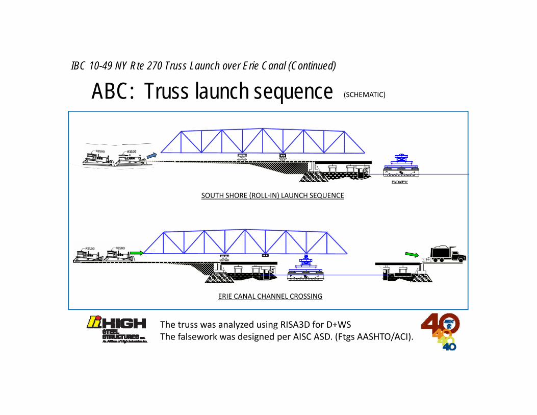
ABC: Truss launch sequence
SOUTH SHORE (ROLL‐IN) LAUNCH SEQUENCE
ERIE CANAL CHANNEL CROSSING
(SCHEMATIC)
LO
LO
LO
IBC 10-49 NY Rte 270 Truss Launch over Erie Canal (Continued)
The truss was analyzed using RISA3D for D+WSThe falsework was designed per AISC ASD. (Ftgs AASHTO/ACI).

NORTH SHORE ROLL‐IN
LO
LOAD TRANSFER (L2‐L8), FINAL ROLL & JACKING DOWN TO FINAL POSITION
LO
IBC 10-49 NY Rte 270 Truss Launch over Erie Canal (Continued)
Bathymetric survey was performed, bc the barge had a bluff stern & raked bow. Draft, freeboard & metacentric considerations were addressed.

L830% D+I
L470% D+I
L6 L0L10
LOAD TRANSFER FROM L4‐L6 (50%/50%) TO L4‐L8 (ON BARGE)
View from South Shore:Load transfer to barge
View from North Shore:Crossing channel
View from North Shore:Truss lands on ending falsework (load transfer from barge)

CASE STUDY VI: I‐695/95, TOWSON MD

IT’S…QUIZ TIME!!!
Erected, propped cantilever
1st girder line held for stability
•250 ft spans•R = 1000 ft+
Question: when checking the stability of an I‐girder during erection, what are four good criteria for the bridge erection engineer to evaluate:
1) LTB (AASHTO LRFD 6.10.8.2.3)2) FLB (AASHTO LRFD 6.10.8.2.2)3) WBB (esp deep, slender webs)4) Web crippling/yielding (brg points)
Answers:
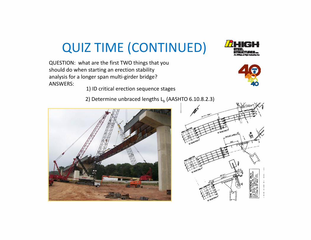
QUIZ TIME (CONTINUED)QUESTION: what are the first TWO things that you should do when starting an erection stability analysis for a longer span multi‐girder bridge?ANSWERS:
1) ID critical erection sequence stages
2) Determine unbraced lengths Lb (AASHTO 6.10.8.2.3)
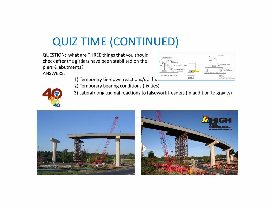
QUIZ TIME (CONTINUED)QUESTION: what are THREE things that you should check after the girders have been stabilized on the piers & abutments?ANSWERS:
1) Temporary tie‐down reactions/uplifts2) Temporary bearing conditions (fixities)3) Lateral/longitudinal reactions to falsework headers (in addition to gravity)

Thanks for your attention.
QUESTIONS ?
So…we want to push this thing over that-away, right?
AUTHOR (S) NAME (S) & LOGO
Fort Belvoir –Mulligan Road ProjectsFairfax Co. VirginiaUS Dept of Transportation (FHWA)Contractor: American InfrastructureErector: High Steel Structures, Inc.
Jockeying girders into position.