The Bearingless Electrical Machine - NASA · The Bearingless Electrical Machine J. Bichsel...
12
The Bearingless Electrical Machine J. Bichsel Institute of Electrotechnical Developments and Constructions Swiss Federal Institute of Technology Zurich, Switzerland https://ntrs.nasa.gov/search.jsp?R=19920018550 2018-09-01T08:06:25+00:00Z
Transcript of The Bearingless Electrical Machine - NASA · The Bearingless Electrical Machine J. Bichsel...
The Bearingless Electrical Machine
J. Bichsel Institute of Electrotechnical Developments and Constructions Swiss Federal Institute of Technology Zurich, Switzerland
https://ntrs.nasa.gov/search.jsp?R=19920018550 2018-09-01T08:06:25+00:00Z
Abstract
Electromagnetic bearings allow the suspension of solids. For rotary applications the most important physical effect is the force of a magnetic circuit to a high-permeable armature, called the MAX- WELL-force. Contrary to the commonly used so called MAXWELL-bearings, the bearingless elec- trical machine will take advantage of the reaction force of a conductor carrying a current in a magnetic field. This kind of force, called LORENTZ-force, generates the torque in direct current, asynchronous and synchronous machines. The magnetic field, which already exists in electrical ma- chines and helps to build up the torque, can also be utilized for the suspension of the rotor. Besides the normal winding of the stator, we have to add a special winding, which generates forces for levita- tion. So a radial bearing, which is integrated directly in the active part of the machine, and the motor use the laminated core simultaneously. The cost for special punching dies can be dropped. Moreover the actual length of the machine is drastically reduced by omitting the space for the conventional MAXWELL-bearing and by the fact that the coil winding heads for LORENTZ-bearings are smal- ler than those for MAXWELL-bearings. Furthermore we are able to construct the winding for the levitating forces in a special way so that commercially available standard ac inverters for drives can be used.
Besides wholly magnetic suspendedmachines, there is a wide range of applications for normal dri- ves with ball bearings. The slots of the laminated cgre will be filled with a winding for the torque and a special winding for the levitating forces, so it is possible to produce forces which suppress me- chanical oscillations. Resonances of the rotor, especially critical speeds, can be dampened actively.
1. Introduction
The goal of the following paper is the derivation and the description of the properties which are ne- cessary to build up a bearingless electrical machine. In chapter two the used symbols are listed and in the third the expressions "the bearingless electrical machine", the "LORENTZ-" and the "MAX- WELL-force" are explained. In chapter four each force is illustrated by an example. Afterwards the basic requirements for radial LORENTZ-bearings are shown in passage five. The properties of the power converter are discussed in the next passage. The seventh section describes a prototype machine with a magnetic-bearing on the basis of the LORENTZ-force which is sucessfully integrated in the active part of an electrical machine, so we have the proof that the bearingless electrical machine is not just an idea but a fact. In the last chapter we make a brief summary and give an outlook for the future.
2. Symbols
B B Ba F M FL F i , ... , F8 I I L1, ... , L4 qa P 0 P r
flux density vector of the flux density flux density in the air gap MAXWELL-force force-vector of the LORENTZ-force forces of a segment of the stator current vector of the length of the machine inductivities area of a magnetic pole permittivity of the vacuum relative permittivity
3. Definitions
In the following chapter we will explain the expressions of Yhe bearingless electrical machine", the "LORENTZ-" and the "MAXWELL-force". These two forces are introduced for a good description of the effects of magnetism.
3.1. The Bearingless Electrical Machine
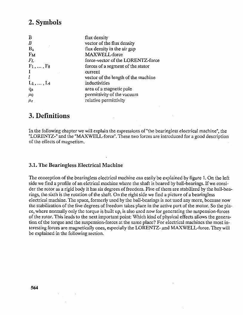
The conception of the bearingless electrical machine can easily be explained by figure 1. On the left side we find a profile of an elctrical machine where the shaft is beared by ball-bearings. If we consi- der the rotor as a rigid body it has six degrees of freedom. Five of them are stabilized by the ball-bea- rings, the sixth is the rotation of the shaft. On the right side we find a picture of a bearingless electrical machine. The space, formerly used by the ball-bearings is not used any more, because now the stabilization of the five degrees of freedom takes place in the active part of the motor. So the pla- ce, where normally only the torque is built up, is also used now for generating the suspension-forces of the rotor. This leads to the next important point: Which kind of physical effects allows the genera- tion of the torque and the suspension-forces at the same place? For electrical machines the most in- teresting forces are magnetically ones, especially the LORENTZ- and MAXWELL-force. They will be explained in the following section.
564
Electro- Bearing Motor Bearlng
Electro-Motor and Bearlng
Figure 1: On the left side: electrical machine with ball-bearings. On the right side: The "bearingless electrical machine".
3.2. Magnetic Forces
Now we will consider two important magnetic forces. To produce a rotation - or better a torque - in electrical machines, like DC, asynchronous or synchronous motors, we use the LORENTZ-force. This force is caused by a conductor carrying a current in a magnetic field. The basic formula is
. F L = I ( Z X B )
with B the vector of the flux density, I the current in the conductor in the magnetic field and Z the vector of the length of the machine. Normally in the magnetic suspension technique we take advan- tage of the force which is caused by a magnetic circuit to a high permeable armature, also called the MAXWELL-force. The most important application is the attracting force of a magnetic field to a co- re assembly in the vacuum. Here the formula for high values of relative permittivity ( p r > > 1 ) is
2 Ba qa 2 Po
FM =
where Ba is the flux density in the air-gap, qa is the active area andPo the permittivity in the vacuum.
Some points are interesting: The LORENTZ-force grows linearly with the B-field and can therefore either be attractive or repulsive. Contrary to this, the MAXWELL-force , whose force grows in square-law to the B-field, can only be attractive, independent of the direction of the B-field.
565
4. Typical Applications for Different Kinds of Magnetic Forces
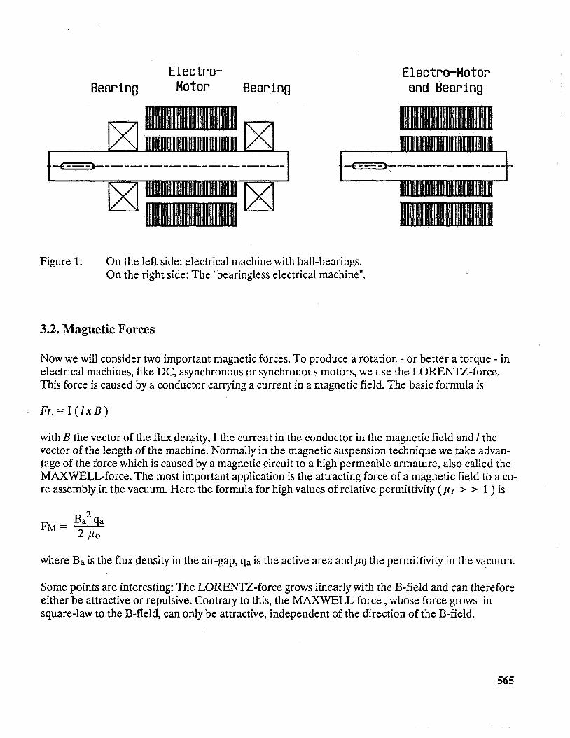
The LORENTZ-force is typically used to produce the torque in electrical machines. The force at the rotor can be calculated by the LORENTZ-force formula or more visual by the right-hand rule where the thumb goes in the direction of the B-field, the forefinger in the direction of the current and the middle finger points in the direction of the force vector. Looking at figure 2 we will get, by dividing the rotor and stator in six sectors, Fi through F6; graphically by the right-hand rule or more mathematically by the LORENTZ-law. With the length 1 of the machine, the current I and the B- field the force-vectors Fi to F6 are determined. Together they form the torque M. With a constant flux density B, the amplitude of the torque can directly be controlled by the amplitude of the cur- rent.
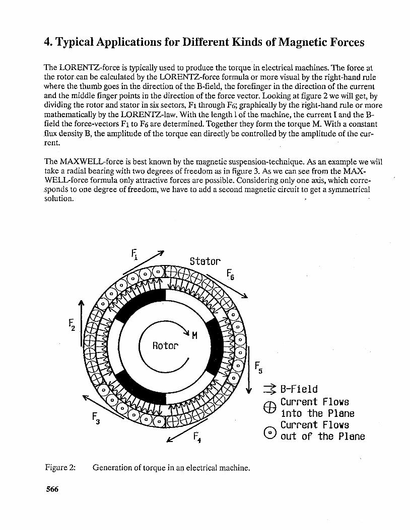
The MAXWELL-force is best known by the magnetic suspension-technique. As an example we will take a radial bearing with two degrees of freedom as in figure 3. As we can see from the MAX- WELL-force formula only attractive forces are possible. Considering only one axis, which corre- sponds to one degree of freedom, we have to add a second magnetic circuit to get a symmetrical solution.
F 2
F 5 + + B-Fleld
Current Flows Into the Plane Current Flows out o f the Plane
Figure 2:
566
Generation of torque in an electrical machine.
L3 E x i t a t ion Sensors
4 2
channels displacement sensors
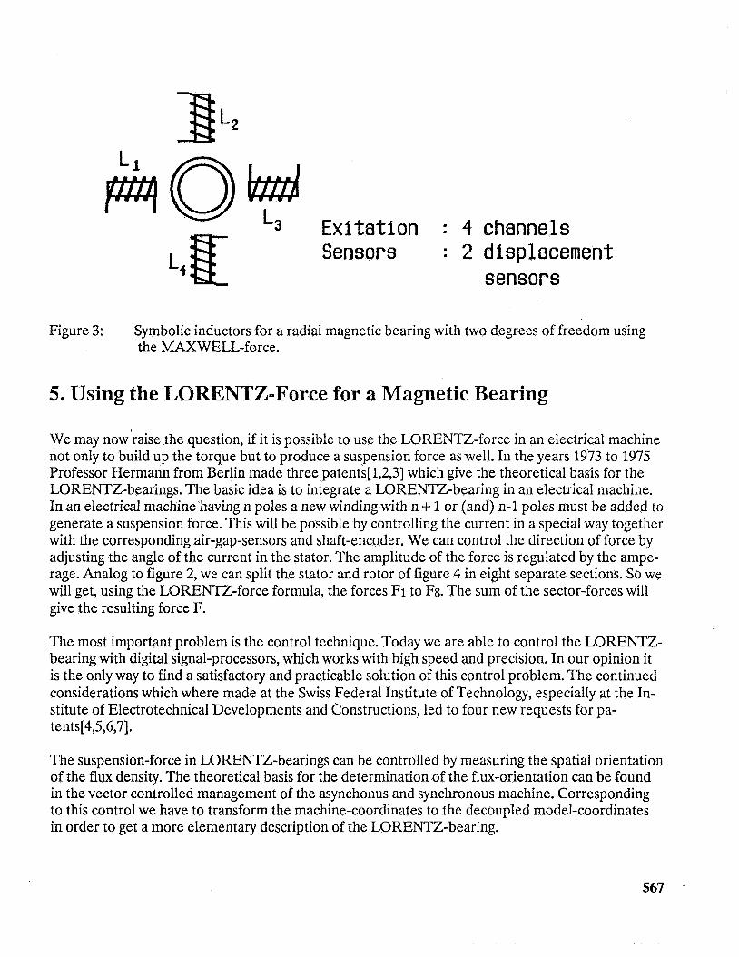
Figure 3: Symbolic inductors for a radial magnetic bearing with two degrees of freedom using the MAXWELL-force.
5. Using the LORENTZ-Force for a Magnetic Bearing
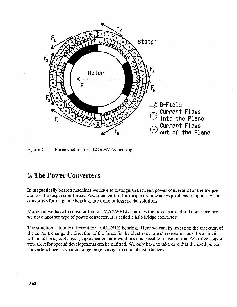
We may now'raise the question, if it is possible to use the LORENTZ-force in an electrical machine not only to build up the torque but to produce a suspension force as well. In the years 1973 to 1975 Professor Hermann from Berlin made three patents[ 1,2,3] which give the theoretical basis for the LORENTZ-bearings. The basic idea is to integrate a LORENTZ-bearing in an electrical machine. In an electrical machine having n poles a new winding with n + 1 or (and) n-1 poles must be added to generate a suspension force. This will be possible by controlling the current in a special way together with the corresponding air-gap-sensors and shaft-encoder. We can control the direction of force by adjusting the angle of the current in the stator. The amplitude of the force is regulated by the ampe- rage. Analog to figure 2, we can split the stator and rotor of figure 4 in eight separate sections. So we will get, using the LORENTZ-force formula, the forces Fi to F8. The sum of the sector-forces will give the resulting force F.
The most important problem is the control technique. Today we are able to control the LORENTZ- bearing with digital signal-processors, which works with high speed and precision. In our opinion it is the only way to find a satisfactory and practicable solution of this control problem. The continued considerations which where made at the Swiss Federal Institute of Technology, especially at the In- stitute of Electrotechnical Developments and Constructions, led to four new requests for pa- tents[4,5,6,7].
The suspension-force in LORENTZ-bearings can be controlled by measuring the spatial orientation of the flux density. The theoretical basis for the determination of the flux-orientation can be found in the vector controlled management of the asynchonus and synchronous machine. Corresponding to this control we have to transform the machine-coordinates to the decoupled model-coordinates in order to get a more elementary description of the LORENTZ-bearing.
567
I
8-F 5 e 1 d Current Flows into the Plane Current Flows out o f the Plane
Figure 4: Force vectors for a LORENTZ-bearing.
6. The Power Converters
In magnetically beared machines we have to distinguish between power converters for the torque and for the suspension-forces. Power converters for torque are nowadays produced in quantity, but converters for magnetic bearings are more or less special solutions.
Moreover we have to consider that for MAXWELL-bearings the force is unilateral and therefore we need another type of power converter. It is called a half-bridge converter.
The situation is totally different for LORENTZ-bearings. Here we can, by inverting the direction of the current, change the direction of the force. So the electronic power converter must be a circuit with a full bridge. By using sophisticated core-windings it is possible to use normal AC-drive conver- ters. Cost for special developments can be omitted. We only have to take care that the used power converters have a dynamic range large enough to control disturbances.
568
7. The Prototype Machine
In the preceding parts of this paper we have described possible solutions which allow us to build up a magnetic bearing with the LORENTZ-force. To verify the theoretical results we have constructed a prototype machine with which we could proof the theory[8].
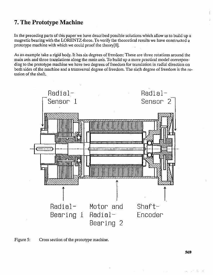
As an example take a rigid body. It has six degrees of freedom: These are three rotations around the main axis and three translations along the main axis. To build up a more practical model correspon- ding to the prototype machine we have two degrees of freedom for translation in radial direction on both sides of the machine and a transversal degree of freedom. The sixth degree of freedom is the ro- tation of the shaft.
Radial- Sensor 1 r '
T
Radial-
T, Radial- Motor and Shaft- Bearing 1 Radial- Encoder
Bearing 2
Figure 5: Cross section of the prototype machine.
569
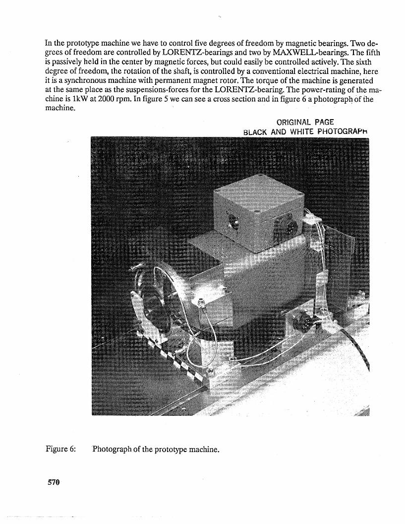
In the prototype machine we have to control five degrees of freedom by magnetic bearings. Two de- grees of freedom are controlled by LORENTZ-bearings and two by MAXWELL-bearings. The fifth is passively held in the center by magnetic forces, but could easily be controlled actively. The sixth degree of freedom, the rotation of the shaft, is controlled by a conventional electrical machine, here it is a synchronous machine with permanent magnet rotor. The torque of the machine is generated at the same place as the suspensions-forces for the LORENTZ-bearing. The power-rating of the ma- chine is 1kW at 2000 rpm. In figure 5 we can see a cross section and in figure 6 a photograph of the machine.
ORIGINAL PAGE
Figure 6: Photograph of the prototype machine.
570
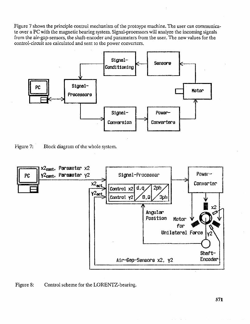
Figure 7 shows the principle control mechanism of the protoype machine. The user can communica- te over a PC with the magnetic bearing system. Signal-processors will analyze the incoming signals from the air-gap-sensors, the shaft-encoder and parameters from the user. The new values for the control-circuit are calculated and sent to the power converters.
Figure 7: BIock diagram of the whole system.
Figure 8: Control scheme for the LORENTZ-bearing.
Figure 8 shows a more detailed picture of the control-mechanism of the LORENTZ-bearing. As a basis we need the signals of the air-gap-sensors and the information of the shaft-encoder. With these data the signal-processor calculates the new values for the power converter in less than 20 ps, inclu- ding the decoupling and transformation of the coordinates.
8. Conclusions
With this paper we have added some new aspects to the magnetic suspension technique. In conven- tional magnetic bearings the attracting force of a magnetic field to a core assembly is used. The newly described LORENTZ-force for a magnetic-levitated-system takes advantage of a conductor carrying a current in a magnetic field. Therefore it is possible to construct new types of machines with bearings integrated in the active part of a motor. On a prototype machine with integrated LO- RENTZ-radial-bearing and a second active MAXWELL-bearing we could prove that this kind of bearing is not only a theoretical game but can be realized with an adequate expenditure.
For the future we have to investigate some important aspects, which are listed below:
0 The mechanical and electrical behaviours of fully integrated machines have to be analyzed.
0 The characteristics of LORENTZ-bearings in high speed applications have to be investigated.
0 A detailed model of the machine, considering effects of saturation, must be gained.
0 A better control technique with observer and state space representation will improve the properties of the LORENTZ-bearing.
e LORENTZ-bearings which are designed for industrial applications must prove their qualities.
572
References
PI
[21
[31
[41
PI
161
171
181
Hermann, P. Deutsche Patent-Auslegeschrift P 23 58 527532,1973
Hermann, P. Deutsche Patent-Offenlegungsschrift P 24 57 0841-32, 1974
Hermann, P. Deutsche Patent-Offenlegungsschrift P 24 06 790.1-32,1975
Bichsel, J. Schweizerisches Patentgesuch Nr. 04 049/90-2, 1990
Bichsel, J. Schweizerisches Patentgesuch Nr. 04 050/90-2, 1990
Bichsel, J. Schweizerisches Patentgesuch Nr. 04 052/90-2,1990
Bichsel, J. Schweizerisches Patentgesuch Nr 04 05 1/90-0, 1990
Bichsel, J. Beitrage zum lagerlosen Elektromotor, Dissertation ETH Zurich, 1990
573