
The all new M6 - IONTOF
17
Content M6 - SIMS technology one step ahead 2 The all new M6 TOF Analyser Nanoprobe 50 High-end Dual Beam Depth Profiling Gas Cluster Ion Source Oxygen Cluster and FIB Applications Sample Heating and Cooling SurfaceLab 7 Hybrid SIMS TOF MS/MS M6 Plus 4 8 10 12 14 18 20 22 26 28 The all new M6 Advanced Ion Beam Technology for Surface Analysis
Transcript of The all new M6 - IONTOF

Content
M6 - SIMS technology one step ahead 2
The all new M6 TOF Analyser
Nanoprobe 50
High-end Dual Beam Depth Profiling
Gas Cluster Ion Source
Oxygen Cluster and FIB Applications
Sample Heating and Cooling
SurfaceLab 7
Hybrid SIMS
TOF MS/MS
M6 Plus
4
8
10
12
14
18
20
22
26
28
The all new M6Advanced Ion Beam Technology for Surface Analysis

High lateral resolution (< 50 nm) with the new Nanoprobe 50
Unique delayed extraction mode for high transmission with high lateral and high mass resolution simultaneously
1
23
Mass resolution > 30,000
TOF MS/MS with CID fragmentation for molecular structure elucidation
45
6
7
Unmatched dynamic range and detection limits
Sophisticated SurfaceLab 7 software including fully integrated Multivariate Statistical Analysis (MVSA) software package
New flexible, push-button, closed-loop sample heating and cooling system for long-term operation without user interaction
The M6 is the latest generation of high-end TOF-SIMS instruments developed by IONTOF. Its design guarantees superior performance in all fields of SIMS applications. New ground-breaking ion beam and mass analyser technologies make the M6 the benchmark in SIMS instrumentation and the ideal tool for industrial and academic research.
M6 - SIMS technology one step ahead

The all new M6 TOF Analyser
Transmission, mass resolution and mass accuracy are the most essential figures of merit for a time-of-flight mass analyser. The M6 reflectron mass analyser features high transmission and high mass resolution. Both are achieved simultaneously and without compromise in positive and negative SIMS.
This new level of performance allows mass interferences of e.g. CH/ C, CH2/N containing molecules to be resolved even in the higher mass range, thus facilitating molecular peak identification.
Furthermore, the achievable mass accuracy is an important prerequisite for clear peak identification. The M6 mass analyser has a linear mass scale and provides superior mass accuracy of less than 10 ppm.
Mass resolution beyond 30,000
The revolutionary new design of the extraction optics and detection system also provides up to three times higher transmission. In combination with high repetition rates and the improved primary ion currents of the Nanoprobe 50, three times lower detection limits can be achieved in dual beam depth profiling.
The new developments also allow for up to threetimes faster imaging. Formerly time consumingimage acquisitions take only a few minutes today.
With the patented extended dynamic range (EDR)analyser technology, seven orders of magnitude ofdynamic range can be achieved. Intensities of more than 100 ions per pulse per mass with an excellent linearity and reproducibility can be recorded.
New level of mass resolution and sensitivity
13
Three times higher sensivity
4
B+
1019
Concentration
1020
1018
1017
1016
1015
atoms / cm3
Depth
200 400 6000nm
High resolution mass spectra demonstrating the new level of mass resolution in the low and high mass range.
Depth profile of a boron NIST implant standard (SRM 2137).
C Hm > 32,000/m
25 30N +3103x
Intensity counts
0
1
2
4
3
372.2372.0
zm/
372.4
CHO
m > 20,500/m
+
+
m > 19,900/m
C H +
m > 19,000/m2 5
m/m
+
> 20,500
SiH28
Si29
103x
Intensity counts
0.0
1.0
0.2
0.4
0.6
0.8
29.0028.95
zm/
29.05
5

The all new M6 TOF Analyser
In conventional TOF-SIMS instruments the mass resolution depends on the pulse width of the primary ion source and hence the resulting acquisition time and image resolution. The delayed extraction mode of the M6 overcomes this restriction and combines maximum image resolution with high spectrometry performance in a unique way. This allows for mass resolutions above 10,000 in combination with lateral resolutions below 50 nm. Previously this mass resolution was only achievable in a dedicated spectrometry mode with limited lateral resolution.
The delayed extraction mode also provides excellent performance on very rough samples and, in combination with the excellent depth-of-field of the M6 extraction optics, significantly reduces any topographic contrast.
Delayed Extraction Mode - Combining ultimate lateral resolution with high mass resolution
10,000 mass resolution with 50 nm lateral resolution
Analysis of the fibre structure of a commercial adhesive bandage showing the surface distribution of C4H9 (red), Na (green) and Al (blue). The image nicely demonstrates the excellent depth-of-field of the M6 TOF analyser.
Al+
C H +2 3104x
Intensity counts
0.0
1.0
2.0
4.0
3.0
26.8
zm/
27.0 27.2
The height difference from the top of the fibres to the aluminium substrate is more than 300 μm. Nevertheless, the corresponding spectrum shows a good mass resolution with clear separation for inorganic and organic peaks.
Overlay: C4H9 (red), Na (green), Al (blue)Primary ion: Bi3 , Field of view: 500 x 500 μm , Pixel size: 1 μm
+ + +
++ 2

Nanoprobe 50
The Nanoprobe 50 is the latest generation bismuth cluster ion source for the M6. The source provides pulsed primary ion currents of up to 40 pA and an ultimate lateral resolution of well below 50 nm. The new bipolar bunching system can operate at repetition rates of up to 50 kHz, allowing for extremely high data rates and improved detection limits. The Nanoprobe 50 is the ideal primary ion source for high lateral resolution microanalysis and imaging as well as high mass resolution surface spectrometry and depth profiling.
50 nm lateral resolution guaranteed and two times higher data rates
More flexibility and fully automated beam alignment
The new Nanoprobe 50 is also equipped with a high-precision aperture exchange system which provides a new level of flexibility in combination with fully automated beam alignment. The operator can select from nine different apertures, which are then quickly (less than 2 s) aligned with nanometer precision, to have the best source setup for the analytical task at hand.
50 nm lateral resolution guaranteed
The new benchmark in cluster ion beam technology
12
3
4
40 nA DC current and up to 40 pA pulsed current
New bipolar bunching system for improved spectrometry performance and ease of operation
In-column measurement of mass separated, pulsed primary ion currents
8
Surface image of C and C labelled Escherichia Coli Cells on silicon showing the surface distribution of CN, CN and Si. For the analysis the delayed extraction mode of the M6 TOF analyser was used to combine ultimate imaging resolution with a mass resolution above 10,000.
Primary ion: Bi3 , Field of view: 15 x 15 μm , Pixel size: 60 nm
Surface image showing the aluminium distribution on a standard test sample (L-200, provided by the German BAM). The image demonstrates a lateral resolution of less than 50 nm.
Primary ion: Bi3 , Field of view: 8 x 8 μm , Pixel size: 15 nm
Overlay: CN (red), CN (green), Si (blue)
70nm
50nm 20nm
100nm
++ 2
12 13
12 13
++ 2
1312 - - -
9

High-end Dual Beam Depth Profiling
The dual source ion column (DSC) is the new high current sputter source for all inorganic depth profiling applications. The ion optical column is equipped with two ion sources, an electron impact gas ion source for operation with O2, Ar or Xe and a thermal ionization caesium ion source.
The M6 can be operated at a repetition rate of upto 50 kHz in full interlaced mode which guaranteesthe highest possible data rates and optimumsample structure sampling.The example shows a depth profile of a buriedmultilayer structure. Due to the high repetition ratethe structure can be resolved despite of the highsputter rate (100 nm/min).
From nm to m – DSC, the high-performance work horse for inorganic depth profiling with O2 and Cs
Quantitative depth profiling in MCs+ Mode
The MCs mode has become very popular in TOF-SIMS because it provides easy quantification on many inorganic sample systems. The M6 with its very high bismuth cluster current, high performance caesium sputter source and the advanced EDR technology is the perfect tool for this extremely powerful analysis mode.
IONTOF’s patented EDR technology uniquely allows the measurement of very high Cs
intensities in parallel with low MCs intensities in order to compensate matrix effects and achieve better quantification, even on multilayer systems.
+
+
+
10
Overview Detail
As-
P2-
101
Intensity counts
104
103
102
100
Depth
400 800 1200 16000nm
480 520
Depthnm
SiCs+
GeCs+
Cs+
28
74
20 40 60 80 100 120 140 1600
Depthnm
1016
Concentration
1024
1025
1023
1022
1021
1020
10
10
1017
18
19
Intensity
107
108
106
105
104
103
102
101
100
atoms / cm3 counts
11
Gas Cluster Ion Source
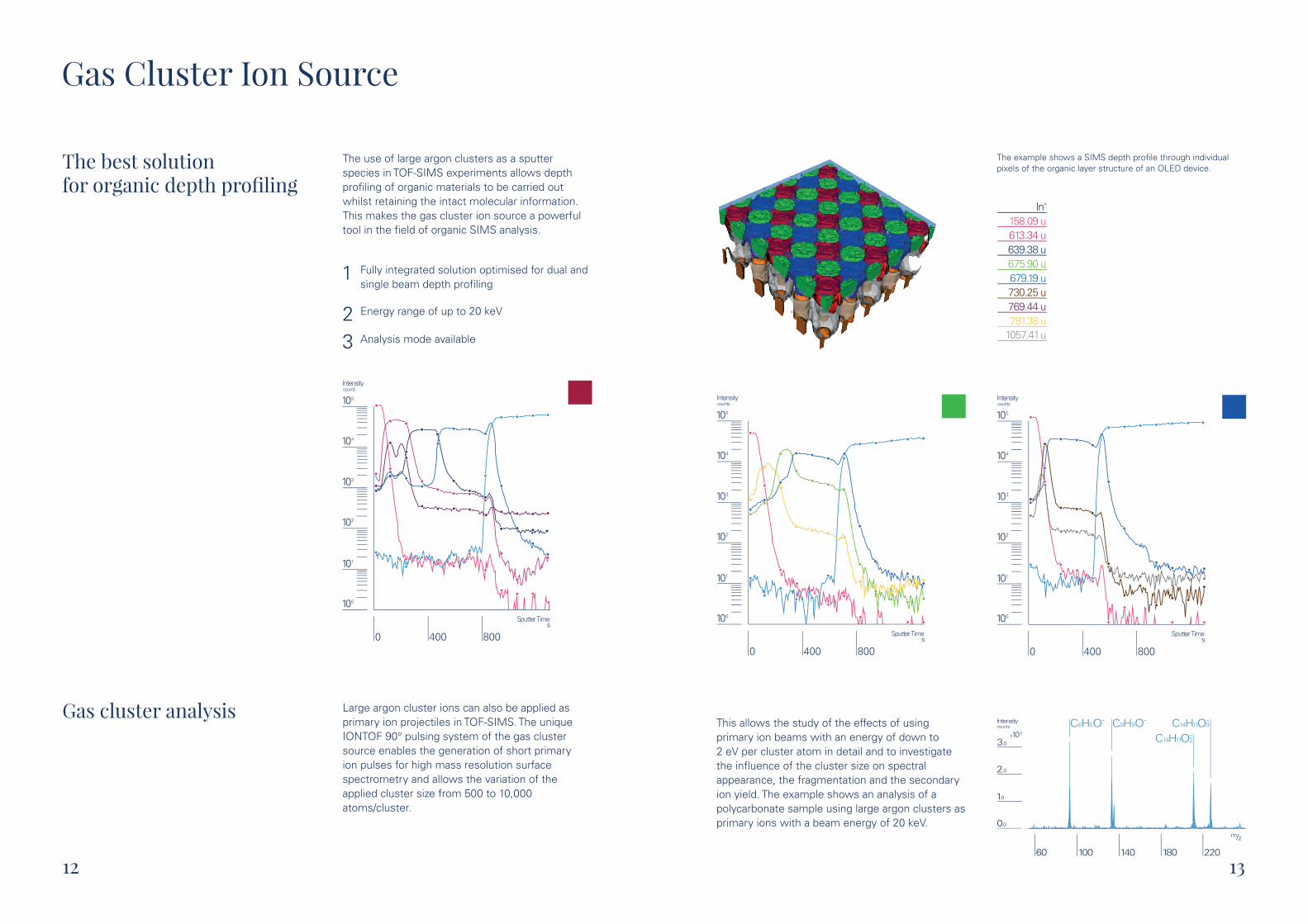
The use of large argon clusters as a sputter species in TOF-SIMS experiments allows depth profiling of organic materials to be carried out whilst retaining the intact molecular information. This makes the gas cluster ion source a powerful tool in the field of organic SIMS analysis.
The best solution for organic depth profiling
Gas cluster analysis Large argon cluster ions can also be applied as primary ion projectiles in TOF-SIMS. The unique IONTOF 90° pulsing system of the gas cluster source enables the generation of short primary ion pulses for high mass resolution surface spectrometry and allows the variation of the applied cluster size from 500 to 10,000 atoms/cluster.
Fully integrated solution optimised for dual and single beam depth profiling
1
23
Energy range of up to 20 keV
Analysis mode available
105
104
103
102
100
101
0 400 800
Intensity counts
Sputter Times
12
The example shows a SIMS depth profile through individual pixels of the organic layer structure of an OLED device.
This allows the study of the effects of using primary ion beams with an energy of down to 2 eV per cluster atom in detail and to investigate the influence of the cluster size on spectral appearance, the fragmentation and the secondary ion yield. The example shows an analysis of a polycarbonate sample using large argon clusters asprimary ions with a beam energy of 20 keV.
105
104
103
102
100
101
0 400 800
Intensity counts
Sputter Times
105
104
103
102
100
101
0 400 800
Intensity counts
Sputter Times
C6H5O- C9H 3O C14H11O- -
2C14H11O-9
18060 100 140 220
Intensity
0.0
2.0
3.0
103x
counts
1.0
zm/
158.09 u613.34 u639.38 u675.90 u679.19 u730.25 u769.44 u781.38 u
1057.41 u
In+
13
Oxygen Cluster and FIB Applications
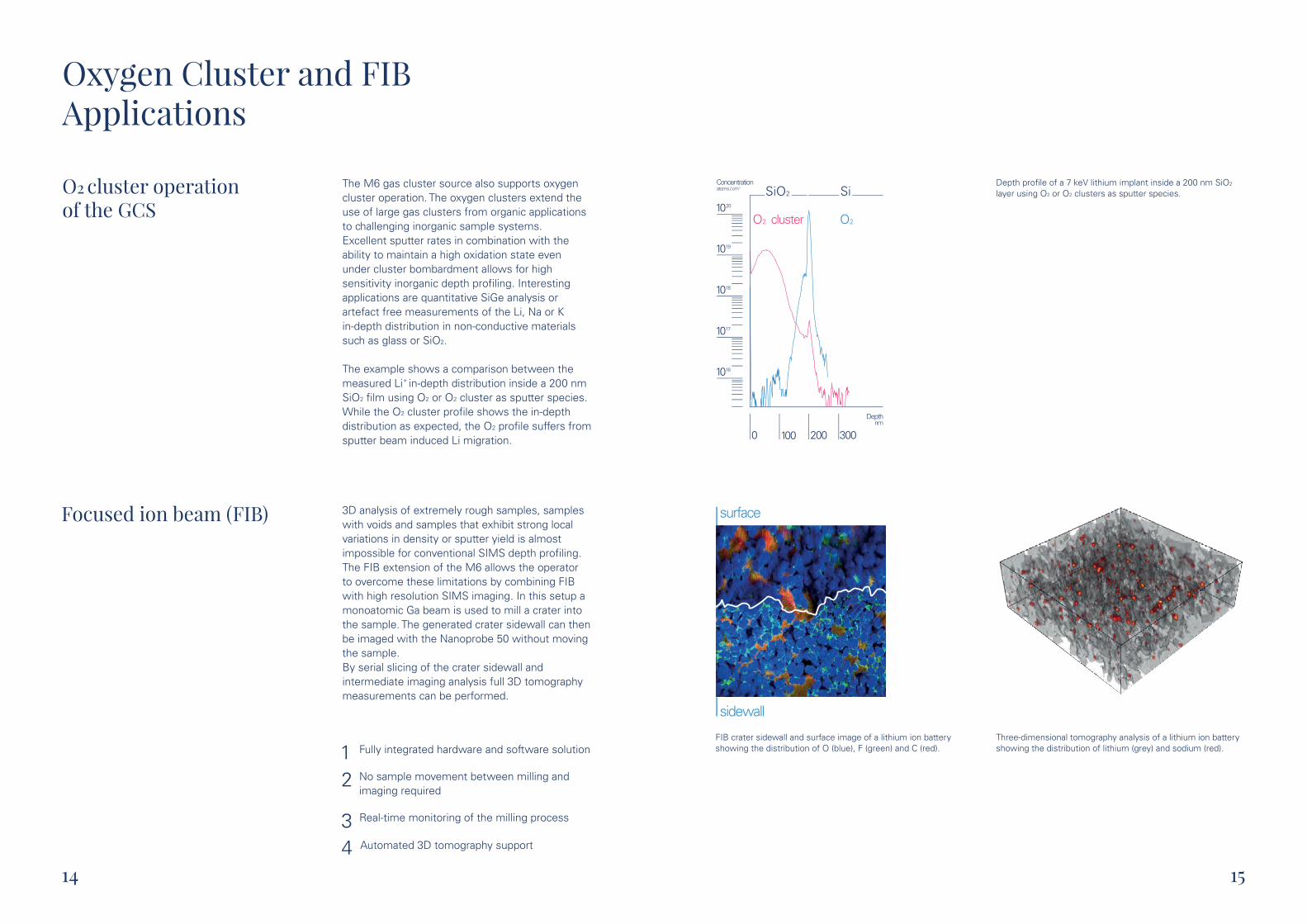
The M6 gas cluster source also supports oxygen cluster operation. The oxygen clusters extend the use of large gas clusters from organic applications to challenging inorganic sample systems. Excellent sputter rates in combination with the ability to maintain a high oxidation state even under cluster bombardment allows for high sensitivity inorganic depth profiling. Interesting applications are quantitative SiGe analysis or artefact free measurements of the Li, Na or K in-depth distribution in non-conductive materials such as glass or SiO2.
The example shows a comparison between the measured Li in-depth distribution inside a 200 nm SiO2 film using O2 or O2 cluster as sputter species.While the O2 cluster profile shows the in-depth distribution as expected, the O2 profile suffers from sputter beam induced Li migration.
O2 cluster operation of the GCS
Focused ion beam (FIB) 3D analysis of extremely rough samples, samples with voids and samples that exhibit strong local variations in density or sputter yield is almost impossible for conventional SIMS depth profiling.The FIB extension of the M6 allows the operator to overcome these limitations by combining FIB with high resolution SIMS imaging. In this setup a monoatomic Ga beam is used to mill a crater into the sample. The generated crater sidewall can then be imaged with the Nanoprobe 50 without moving the sample.By serial slicing of the crater sidewall and intermediate imaging analysis full 3D tomography measurements can be performed.
Fully integrated hardware and software solution12
34
No sample movement between milling and imaging required
Real-time monitoring of the milling process
Automated 3D tomography support
+
14
FIB crater sidewall and surface image of a lithium ion battery showing the distribution of O (blue), F (green) and C (red).
Depth profile of a 7 keV lithium implant inside a 200 nm SiO2 layer using O2 or O2 clusters as sputter species.SiO2 Si
O2 O2cluster
1019
Concentration atoms / cm
1020
1018
1017
1016
Depth
200 3000nm
100
3
Three-dimensional tomography analysis of a lithium ion battery showing the distribution of lithium (grey) and sodium (red).
surface
sidewall
15
surface
sidewall
surface
sidewall

made for industrial
The all new M6
and academic research

Sample Heating and Cooling
The new sample heating and cooling system of the M6 combines unique performance with ease of operation. The closed-loop liquid nitrogen pumping system allows for push-button sample cooling operation in the analysis chamber and the load lock for more than 24 hours without user interaction.
The newly designed sample holder provides high flexibility in terms of sample size and permits full sample movement in all stage axes during sample cooling or heating.
Ultra fast and efficient closed-loop cooling system
Complete mobility of all stage axes incl. rotation and tilt
1
2
34
Allows for large area scans of cooled or heated samples
Extremely short cool down times
Low LN2 consumption (< 0.5 l/hour)
The example shows the temperature dependence of polystyrene oligomers. For the analysis the temperature was increased from -100 °C to 500 °C with a heating rate of 0.3 °C per second.
18
Surface spectra of the polystyrene sample at different temperature ranges.
Intensity of different polystyrene oligomer signals as a function of sample surface temperature.1.0
0.8
0.6
0.4
0
0.2
-100 0 100
Temperature°C
200
Normalised to Maximum
300 400
142 C - 175 C
300 C - 333 C
336 C - 369 C
10 26242220 302812 14 16 18n=
102x
Intensity counts
0
1
0
2
4
0
2
1
30002500
zm/
1500 2000
°°
°°
°°
n
n = 10n = 12n = 14n = 16n = 18n = 20n = 22n = 24n = 26n = 28n = 30
19
SurfaceLab 7
SurfaceLab 7 is the most recent instrument operation, data acquisition and data analysis software for all IONTOF instruments. With this versatile software package IONTOF provides a professional solution for today‘s academic and industrial laboratories.
The extremely powerful interactive data analysis system makes time consuming data reconstruction obsolete and has revolutionised the way TOF-SIMS data is handled today. The software also includes a fully integrated Multivariate Statistical Analysis (MVSA) software package for spectra, images, depth profiles and 3D data.
Comprehensive interactive data analysis
Interactive data analysis1234
Fully integrated MVSA software package
Fully integrated spectra library
Advanced scripting and automation capabilities
Multivariate Statistical Analysis
MVSA refers to a set of statistical methods which examine relationships among multiple variables at the same time. It is often used to reduce the degree of complexity in a data set by reducing the number of variables without compromising the essential information. SurfaceLab 7 includes the following MVSA methods:
Principle Component Analysis (PCA) 123
Maximum Autocorrelation Factors (MAF)
Multivariate Curve Resolution (MCR)
20
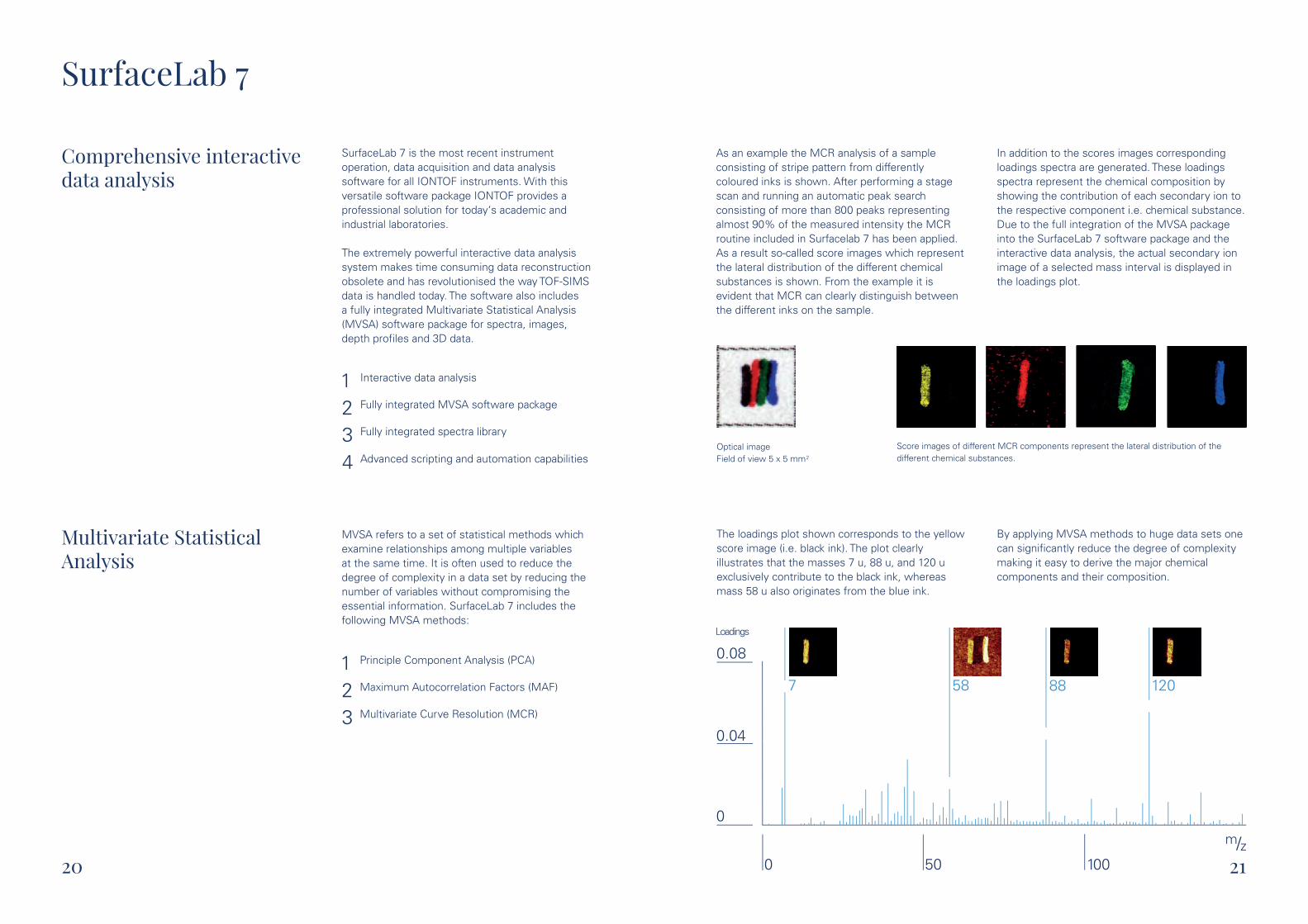
Score images of different MCR components represent the lateral distribution of the different chemical substances.
The loadings plot shown corresponds to the yellow score image (i.e. black ink). The plot clearly illustrates that the masses 7 u, 88 u, and 120 u exclusively contribute to the black ink, whereas mass 58 u also originates from the blue ink.
By applying MVSA methods to huge data sets one can significantly reduce the degree of complexity making it easy to derive the major chemical components and their composition.
0.08
0
0.04
0 50
Loadings
100
58 887 120
zm/
9
As an example the MCR analysis of a sample consisting of stripe pattern from differently coloured inks is shown. After performing a stage scan and running an automatic peak search consisting of more than 800 peaks representing almost 90% of the measured intensity the MCR routine included in Surfacelab 7 has been applied. As a result so-called score images which represent the lateral distribution of the different chemical substances is shown. From the example it is evident that MCR can clearly distinguish between the different inks on the sample.
In addition to the scores images corresponding loadings spectra are generated. These loadings spectra represent the chemical composition by showing the contribution of each secondary ion to the respective component i.e. chemical substance. Due to the full integration of the MVSA package into the SurfaceLab 7 software package and the interactive data analysis, the actual secondary ion image of a selected mass interval is displayed in the loadings plot.
Optical imageField of view 5 x 5 mm
21
2

M6 Hybrid SIMS
Surface analysis meets
organic mass spectrometry

The first example shows the analysis of a humanbone section. Mass intervals representing the collagenous fibres within the bone marrow are shown in red. In blue, the distribution of C5H15NPO4 is shown, corresponding to thephosphatidylcholine head group.
+
Hybrid SIMS
With the Q Exactive extension for the M6, IONTOF provides the first commercial SIMS instrument which combines the highest mass resolution (> 240,000) and highest mass accuracy (< 1 ppm) with high resolution cluster SIMS imaging.The combination of the fast imaging capabilities of the TOF analyser with the unique performance of the Q Exactive for unambiguous peak identification provides a new level of SIMS information from organic samples.The new instrument extension also provides field proven, high-end MS/MS capabilities and sets a new benchmark for high resolution molecular SIMS applications.
Surface analysis meetsorganic mass spectrometry
Dual analyser configuration with TOF and Orbitrap
1
2
3
4
High resolution gas cluster imaging and spectrometry beyond the static SIMS limit
Mass resolution > 240,000 and < 1 ppm mass accuracy
High resolution MS/MS capabilities
The powerful combination of the gas cluster ionsource and the Orbitrap analyser enables the distinction of different features even in highly complex organic samples.For all spectra shown in the two examples thesame level of mass resolution and mass accuracyis obtained. Both are a prerequisite for unambiguous peak identification.
TM
TM
TM
24
TM
F-
m 0.3 ppm
-
3C10N2F-
-F
-CN
-CF
m -0.1 ppm
2C10N3F-
m 0.2 ppm
3C9N2F-
m -0.4 ppm
2C9N3F
m 0.1 ppm
-3C8N2F
m 0.3 ppm
-3C7N2F
m 0.5 ppm
-C7N2
3C11N3m 0.2 ppm
C12N4F-
m 0.6 ppm2
F-3C11N4
m 0.2 ppm
F-4C11N3
m 0.3 ppm
C12N4F-
m 0.7 ppm3
C12N4F-
m -0.1 ppm4
precursor
m -0.2 ppm
R 260 000
F-4
m -0.2 ppm
R 258 000
C11N
F-C9N3 3
F-C11N3m 0.2 ppm
R 255 000
F-C9N2m 0.2 ppm
R 247 000
4
2
170100 230 260
207.02207.00206.98 211.97 211.99 212.01
zm/
zm/
FF
FF
CN
CN
NC
NC
The second example shows a high resolutionstructural analysis of a molecule used for OLEDdevices. The overview spectrum displays the fullMS/MS information for the precursor ion C12N4F4
.The detail spectra show plots of different fragmentions.
286.8831 uPO8
+Ca3H8
0.6 ppmR=222510
1
3
106x
Intensity a.u.
4
2
zm/
286.875286.850
184.0725 uNPO4
+C5H15
-0.25 ppmR=234464
Substrate
15
10
5
105x
Intensity a.u.
184.07184.05
zm/
184.09
288.8604 uP6
+C7H3
-0.1 ppmR=225783
O
1
3
106x
Intensity a.u.
4
2
288.85288.80
zm/
F-
m 0.3 ppm
-
3C10N2F-
-F
-CN
-CF
m -0.1 ppm
2C10N3F-
m 0.2 ppm
3C9N2F-
m -0.4 ppm
2C9N3F
m 0.1 ppm
-3C8N2F
m 0.3 ppm
-3C7N2F
m 0.5 ppm
-C7N2
3C11N3m 0.2 ppm
C12N4F-
m 0.6 ppm2
F-3C11N4
m 0.2 ppm
F-4C11N3
m 0.3 ppm
C12N4F-
m 0.7 ppm3
C12N4F-
m -0.1 ppm4
precursor
m -0.2 ppm
R 260 000
F-4
m -0.2 ppm
R 258 000
C11N
F-C9N3 3
F-C11N3m 0.2 ppm
R 255 000
F-C9N2m 0.2 ppm
R 247 000
4
2
170100 230 260
207.02207.00206.98 211.97 211.99 212.01
zm/
zm/
-
Courtesy of Kaija Schäpe and Dr. Marcus Rohnke (University of Gießen, Germany)
480 µm
25

TOF MS/MS
Time-of-Flight SIMS is an excellent technique for the characterisation of organic surfaces and layer systems. However, interpretation of organic spectra can be quite challenging and requires a reasonably experienced user. To facilitate data interpretation IONTOF provides different tools such as spectra libraries, a fully integrated Multivariate Statistical Analysis (MVSA) software package and the ultimate performance Q ExactiveTM extension for the M6, which provides highest mass resolution (> 240,000), highest mass accuracy (< 1 ppm) and high-end MS/MS.
With the new ToF MS/MS option IONTOF now also offers a more cost effective MS/MS solution for the M6. The option is ideally suited for quick confirmation of anticipated contaminants or compositions and fast MS/MS imaging or depth profiling applications. Key features of the new TOF MS/MS are:
High transmission (> 80%) and sensitivity12
3
4
High mass resolution precursor selection to avoid MS2 fragmentation pattern interferences
Sequential, full MS1 and MS2 data streams with individually optimised analysis conditions
Fully automated multiple precursor MS/MS acquisition
5 No limitation for the MS1 performance regarding angular acceptance, transmission or mass resolution
High transmission, high mass resolution precursor selection and MS/MS imaging
The first example shows the MS/MS analysis of a mixture of tributyl citrate and glyceryl monostearate. Both molecules show a characteristic molecular peak at the same nominal mass. With the unique high mass resolution precursor selection it is possible to generate individual MS2 spectra of the different molecules and to avoid fragmentation pattern interferences.
26 27
C21H O43 4+
O
O
O
+
O
O O
O
+
+OH
OHO
OH+
Glyceryl monostearate
OHO
O
+
C18H O31 7+Tributyl citrate
O
O+
HO
O
O
O+
HO
O
O
O
+HOO
OHOO+
HO
O
O
O+102x
Intensity counts
0
2
Intensity counts
0
20
40
60
0
10
5
300
zm/
100 200
0.1x
0.1x
359.5
zm/
358.5
The second example shows a high resolution MS/MS imaging analysis of Tinuvin 770 blooming on a small field of view (100 x 100 μm ), demonstrating the superior transmission of the IONTOF TOF MS/MS system.
The corresponding MS2 spectrum allows for the clear identification of characteristic molecular fragments.
MS2 spectra and MS2 image of Tinuvin 770.Field of view: 100 x 100 μm
103x
Intensity counts
0
6
3
0.1x
+
O
O
O
O
NH
NH2
+O
O O
NH
OH2
+
NH
+
400
zm/
100 200 300
2
2

M6 Plus - The tool for nano characterisation

M6 Plus
Information concerning chemical composition, physical properties and the three-dimensional structure of materials and devices at the nanometre scale is of major importance for new developments in nanoscience and nanotechnology. In a 3D SIMS measurement the initial topography of the sample surface as well as topographic changes during the experiment cannot be easily identified.
Scanning Probe Microscopy (SPM) provides complementary information about the surface topography and can also be used to measure the physical properties of the analysed sample.
Through the combination of these two techniques true in-situ three-dimensional chemical imaging becomes possible.
The new M6 Plus platform combines the high-end performance of the M6 with the possibility to perform in situ SPM measurements. The SPM unit with its large scan range is ideally suited to provide topographic information for true 3D SIMS measurements.
A powerful platform for nano characterisation
All standard SPM modes e.g. AFM, MFM, KPFM, multi-frequency
1
2
3
Large SPM scan range of 80 x 80 x 10 μm
Unique surface profiler mode for large SIMS sputter crater measurements
3
The piezo sample stage of the M6 Plus with sub-micron position accuracy ensures fast and precise movement between the TOF-SIMS and the SPM measurement position. The stage has a10 nm encoder resolution and travel speeds of up to 10 mm/s which guarantees a new level of precision and stability.
3D overlay without topography correction: SiN (red), Ge (orange), SiO2 (yellow) and Si (green).Field of view: 25 x 25 μm 2
3D overlay with topography correction: SiN (red), Ge (orange), SiO2 (yellow) and Si (green).Field of view: 25 x 25 μm 2

Notes
Heisenbergstraße 1548149 MünsterGermany
Phone +49 251 1622-100Email [email protected] www.iontof.com