The Active Optics System for the Discovery Channel...
21
Copyright 2010 Society of Photo-Optical Instrumentation Engineers (SPIE Proceedings 7739-63). One print or electronic copy may be made for personal use only. Systematic reproduction and distribution, duplication of any material in this paper for a fee or for commercial purposes, or modification of the content of the paper are prohibited. The Active Optics System for the Discovery Channel Telescope Byron Smith* a , Tomas Chylek a , Brian Cuerden b , Bill DeGroff a , Paul J. Lotz a , Alexander Venetiou a a Lowell Observatory, 1400 W. Mars Hill Road, Flagstaff, AZ 86001; b University of Arizona College of Optical Sciences, 1630 E. University Blvd., Tucson, AZ 85721 ABSTRACT The Discovery Channel Telescope (DCT) is a 4.3-meter telescope designed for dual optical configurations, featuring an f/6.1 Ritchey-Chretien prescription with a 0.5° field-of-view, and a corrected f/2.3 prime focus with a 2° field-of-view. The DCT Active Optics System (AOS) maintains collimation and mirror figure to provide seeing limited images across the focal planes and rapid settling times to minimize observing overhead, using a combination of feed-forward and low- bandwidth feedback control via wavefront sensing. Collimation is maintained by tip-tilt-piston control of the M2 assembly and articulating M1 within its cell, taking advantage of the 120 degree-of-freedom support used for figure control. We present an overview of the AOS design and principles of operation, and a summary of progress and results to date. Keywords: DCT, Lowell Observatory, Active Optics, opto-mechanics, wavefront control 1. INTRODUCTION The Active Optics System (AOS) for the Discovery Channel Telescope (DCT) is responsible for maintaining the figure and collimation of the telescope optics and consequently plays a major role in the quality of the images delivered for science. The AOS consists of active supports for the primary and secondary mirrors, the controls for those supports, and an overarching control system which commands the individual mirror supports to maintain the wavefront quality based on calibration data and feedback from a wavefront sensor. This paper describes these components, and their development as part of the DCT project, including the performance and figure control analysis for the primary mirror. DCT requirements to support large instrument payloads at both prime and Ritchey-Chrétien foci, and high-cadence observations for survey work, drive some notable features of the AOS. In the prime focus configuration, collimation is achieved by articulating the primary mirror on its support. This created a challenge to extend the performance of the support from a single nominal operating position to a significant range of travel, but also takes advantage of otherwise required hardware and eliminates the need for an active positioner for the prime focus instrument. To support high- cadence observations, short settling times (<8 seconds) after a telescope move are required. This is accomplished by utilizing mirror support bandwidths comparable to the mount control bandwidth, driven by a combination of feed- forward control based on calibration data and low-bandwidth wavefront feedback. When not driven by requirements, novel approaches were generally avoided, relying instead on proven strategies for accomplishing goals. 2. AOS OVERVIEW The DCT Active Optics System (AOS) maintains collimation and mirror figure to provide seeing limited images. The AOS can operate open loop and closed loop. Open loop AOS operation maintains collimation and M1 mirror figure with operational parameters and calibration data. Closed loop AOS operation maintains collimation and M1 mirror figure with operational parameters, calibration data, and wavefront data. See Figure 1 for the M1 portion of the AOS. * [email protected]; phone: 928-233-3258; fax: 928-233-3268; lowell.edu
Transcript of The Active Optics System for the Discovery Channel...
Copyright 2010 Society of Photo-Optical Instrumentation Engineers (SPIE Proceedings 7739-63). One print or electronic copy may
be made for personal use only. Systematic reproduction and distribution, duplication of any material in this paper for a fee or for
commercial purposes, or modification of the content of the paper are prohibited.
The Active Optics System for the Discovery Channel Telescope
Byron Smith*a, Tomas Chylek
a, Brian Cuerden
b, Bill DeGroff
a,
Paul J. Lotza, Alexander Venetiou
a
aLowell Observatory, 1400 W. Mars Hill Road, Flagstaff, AZ 86001;
bUniversity of Arizona College of Optical Sciences, 1630 E. University Blvd., Tucson, AZ 85721
ABSTRACT
The Discovery Channel Telescope (DCT) is a 4.3-meter telescope designed for dual optical configurations, featuring an
f/6.1 Ritchey-Chretien prescription with a 0.5° field-of-view, and a corrected f/2.3 prime focus with a 2° field-of-view.
The DCT Active Optics System (AOS) maintains collimation and mirror figure to provide seeing limited images across
the focal planes and rapid settling times to minimize observing overhead, using a combination of feed-forward and low-
bandwidth feedback control via wavefront sensing. Collimation is maintained by tip-tilt-piston control of the M2
assembly and articulating M1 within its cell, taking advantage of the 120 degree-of-freedom support used for figure
control. We present an overview of the AOS design and principles of operation, and a summary of progress and results
to date.
Keywords: DCT, Lowell Observatory, Active Optics, opto-mechanics, wavefront control
1. INTRODUCTION
The Active Optics System (AOS) for the Discovery Channel Telescope (DCT) is responsible for maintaining the figure
and collimation of the telescope optics and consequently plays a major role in the quality of the images delivered for
science. The AOS consists of active supports for the primary and secondary mirrors, the controls for those supports, and
an overarching control system which commands the individual mirror supports to maintain the wavefront quality based
on calibration data and feedback from a wavefront sensor. This paper describes these components, and their
development as part of the DCT project, including the performance and figure control analysis for the primary mirror.
DCT requirements to support large instrument payloads at both prime and Ritchey-Chrétien foci, and high-cadence
observations for survey work, drive some notable features of the AOS. In the prime focus configuration, collimation is
achieved by articulating the primary mirror on its support. This created a challenge to extend the performance of the
support from a single nominal operating position to a significant range of travel, but also takes advantage of otherwise
required hardware and eliminates the need for an active positioner for the prime focus instrument. To support high-
cadence observations, short settling times (<8 seconds) after a telescope move are required. This is accomplished by
utilizing mirror support bandwidths comparable to the mount control bandwidth, driven by a combination of feed-
forward control based on calibration data and low-bandwidth wavefront feedback. When not driven by requirements,
novel approaches were generally avoided, relying instead on proven strategies for accomplishing goals.
2. AOS OVERVIEW
The DCT Active Optics System (AOS) maintains collimation and mirror figure to provide seeing limited images. The
AOS can operate open loop and closed loop. Open loop AOS operation maintains collimation and M1 mirror figure with
operational parameters and calibration data. Closed loop AOS operation maintains collimation and M1 mirror figure
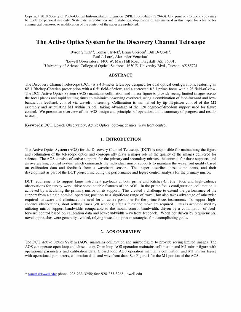
with operational parameters, calibration data, and wavefront data. See Figure 1 for the M1 portion of the AOS.
* [email protected]; phone: 928-233-3258; fax: 928-233-3268; lowell.edu
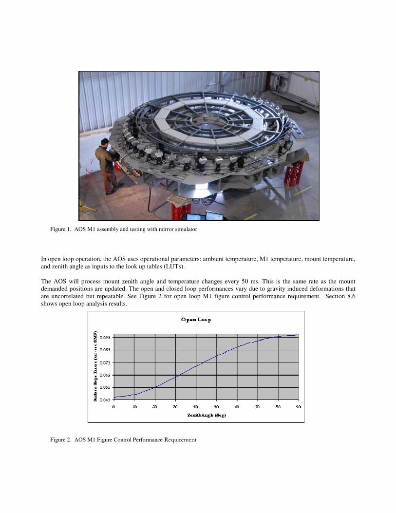
In open loop operation, the AOS uses operational parameters: ambient temperature, M1 temperature, mount temperature,
and zenith angle as inputs to the look up tables (LUTs).
The AOS will process mount zenith angle and temperature changes every 50 ms. This is the same rate as the mount
demanded positions are updated. The open and closed loop performances vary due to gravity induced deformations that
are uncorrelated but repeatable. See Figure 2 for open loop M1 figure control performance requirement. Section 8.6
shows open loop analysis results.
Figure 2. AOS M1 Figure Control Performance Requirement
Figure 1. AOS M1 assembly and testing with mirror simulator
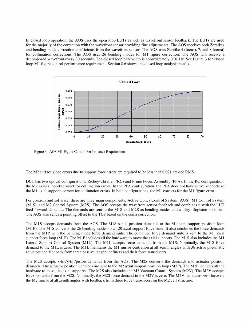
In closed loop operation, the AOS uses the open loop LUTs as well as wavefront sensor feedback. The LUTs are used
for the majority of the correction with the wavefront sensor providing fine adjustments. The AOS receives both Zernikes
and bending mode correction coefficients from the wavefront sensor. The AOS uses Zernike 4 (focus), 7, and 8 (coma)
for collimation corrections. The AOS uses 26 bending modes for M1 figure correction. The AOS will receive a
decomposed wavefront every 30 seconds. The closed loop bandwidth is approximately 0.01 Hz. See Figure 3 for closed
loop M1 figure control performance requirement. Section 8.6 shows the closed loop analysis results.
The M2 surface slope errors due to support force errors are required to be less than 0.021 arc-sec RMS.
DCT has two optical configurations: Richey-Chretien (RC) and Prime Focus Assembly (PFA). In the RC configuration,
the M2 axial supports correct for collimation errors. In the PFA configuration, the PFA does not have active supports so
the M1 axial supports correct for collimation errors. In both configurations, the M1 corrects for the M1 figure error.
For controls and software, there are three main components: Active Optics Control System (AOS), M1 Control System
(M1S), and M2 Control System (M2S). The AOS accepts the wavefront sensor feedback and combines it with the LUT
feed-forward demands. The demands are sent to the M1S and M2S as bending modes and x-tilt/y-tilt/piston positions.
The AOS also sends a pointing offset to the TCS based on the coma correction.
The M1S accepts demands from the AOS. The M1S sends position demands to the M1 axial support position loop
(M1P). The M1S converts the 26 bending modes to a 120 axial support force suite. It also combines the force demands
from the M1P with the bending mode force demand suite. The combined force demand suite is sent to the M1 axial
support force loop (M1F). The M1F includes all the hardware to move the axial supports. The M1S also includes the M1
Lateral Support Control System (M1L). The M1L accepts force demands from the M1S. Nominally, the M1S force
demand to the M1L is zero. The M1L maintains the M1 mirror centration at all zenith angles with 36 active pneumatic
actuators and feedback from three passive tangent definers and their force transducers.
The M2S accepts x-tilt/y-tilt/piston demands from the AOS. The M2S converts the demands into actuator position
demands. The actuator position demands are sent to the M2 axial support position loop (M2P). The M2P includes all the
hardware to move the axial supports. The M2S also includes the M2 Vacuum Control System (M2V). The M2V accepts
force demands from the M2S. Nominally, the M2S force demand to the M2V is zero. The M2V maintains zero force on
the M2 mirror at all zenith angles with feedback from three force transducers on the M2 cell structure.
Figure 3. AOS M1 Figure Control Performance Requirement
3. OPTO-MECHANICS
3.1 Primary mirror supports and auxiliary systems
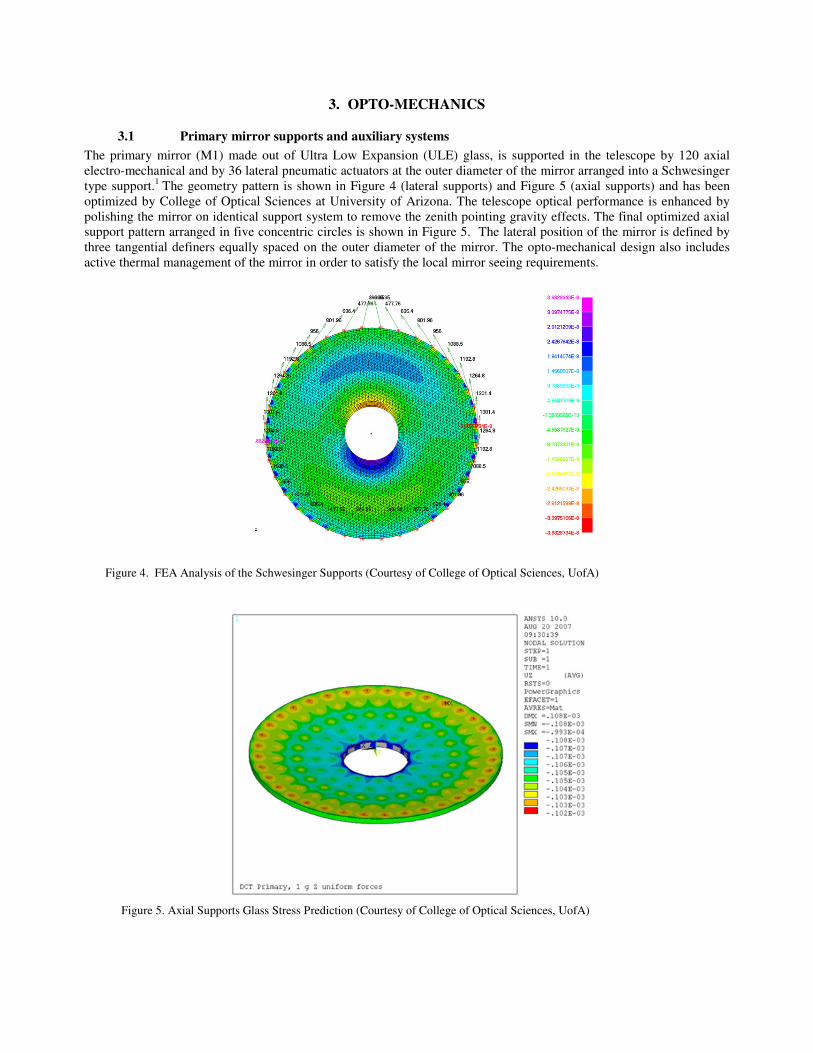
The primary mirror (M1) made out of Ultra Low Expansion (ULE) glass, is supported in the telescope by 120 axial
electro-mechanical and by 36 lateral pneumatic actuators at the outer diameter of the mirror arranged into a Schwesinger
type support.1
The geometry pattern is shown in Figure 4 (lateral supports) and Figure 5 (axial supports) and has been
optimized by College of Optical Sciences at University of Arizona. The telescope optical performance is enhanced by
polishing the mirror on identical support system to remove the zenith pointing gravity effects. The final optimized axial
support pattern arranged in five concentric circles is shown in Figure 5. The lateral position of the mirror is defined by
three tangential definers equally spaced on the outer diameter of the mirror. The opto-mechanical design also includes
active thermal management of the mirror in order to satisfy the local mirror seeing requirements.
Figure 4. FEA Analysis of the Schwesinger Supports (Courtesy of College of Optical Sciences, UofA)
Figure 5. Axial Supports Glass Stress Prediction (Courtesy of College of Optical Sciences, UofA)
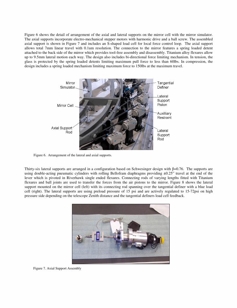
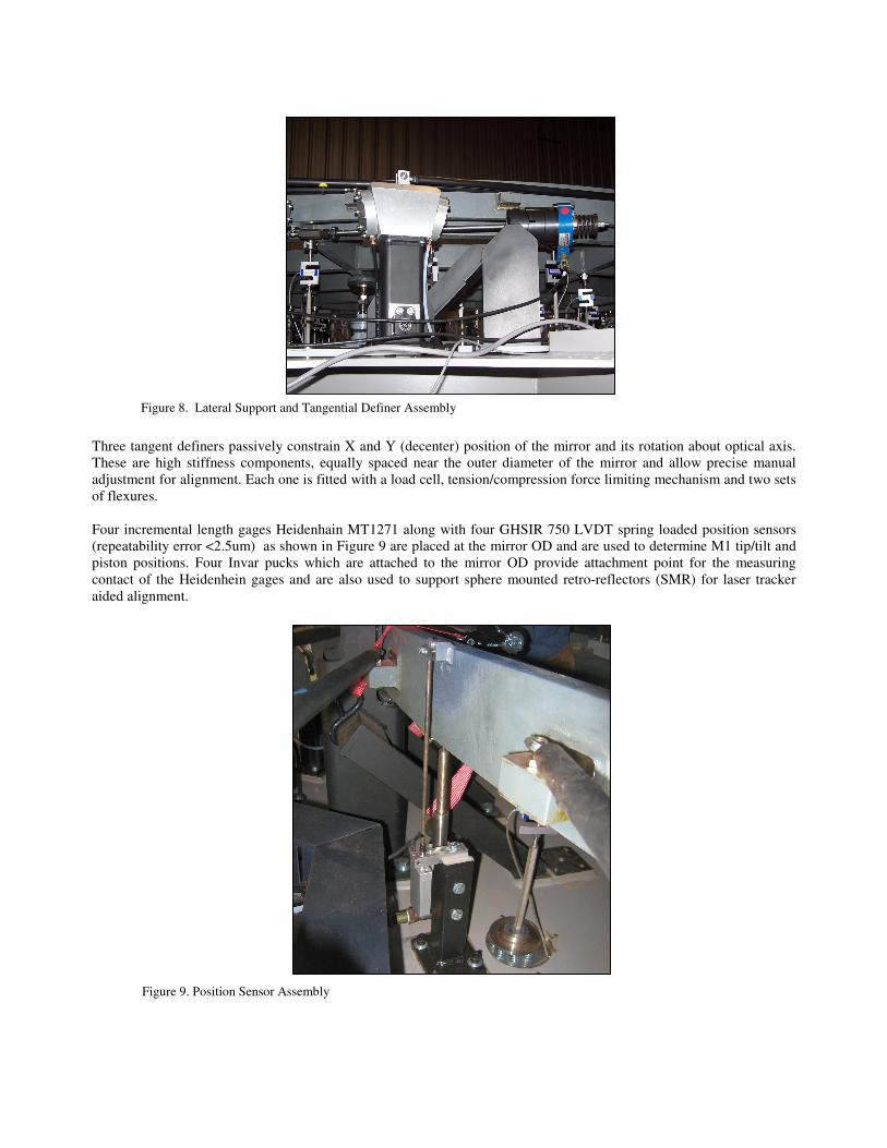
Figure 6 shows the detail of arrangement of the axial and lateral supports on the mirror cell with the mirror simulator.
The axial supports incorporate electro-mechanical stepper motors with harmonic drive and a ball screw. The assembled
axial support is shown in Figure 7 and includes an S-shaped load cell for local force control loop. The axial support
allows total 7mm linear travel with 0.1um resolution. The connection to the mirror features a spring loaded detent
attached to the back side of the mirror which provides tool-free assembly and disassembly. Titanium alloy flexures allow
up to 9.5mm lateral motion each way. The design also includes bi-directional force limiting mechanism. In tension, the
glass is protected by the spring loaded detents limiting maximum pull force to less than 60lbs. In compression, the
design includes a spring loaded mechanism limiting maximum force to 150lbs at the maximum travel.
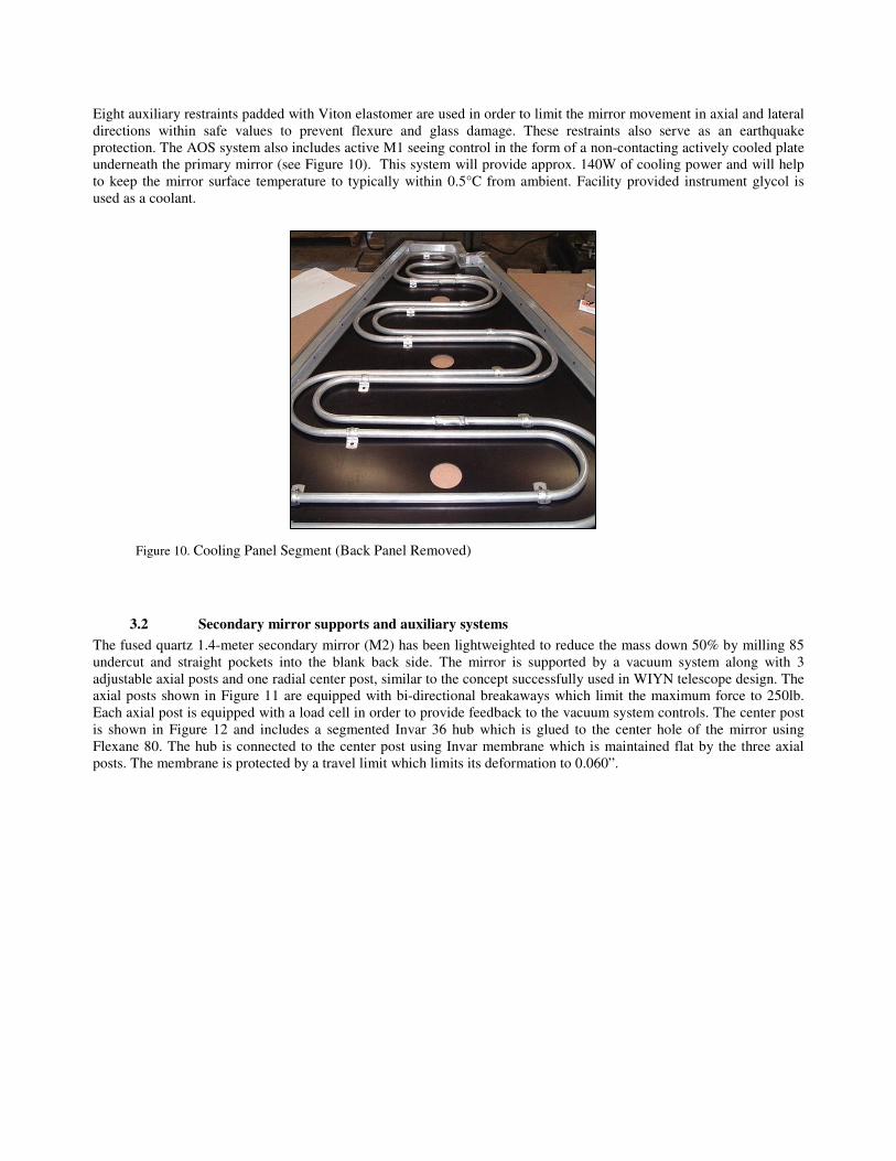
Thirty-six lateral supports are arranged in a configuration based on Schwesinger design with β=0.76. The supports are
using double-acting pneumatic cylinders with rolling Bellofram diaphragms providing ±0.25” travel at the end of the
lever which is pivoted in Riverhawk single ended flexures. Connecting rods of varying lengths fitted with Titanium
flexures and ball joints are used to transfer the forces from the air pistons to the mirror. Figure 8 shows the lateral
support mounted on the mirror cell (left) with its connecting rod spanning over the tangential definer with a blue load
cell (right). The lateral supports are using preload pressure of 15 psi and are actively regulated to 15-72psi on high
pressure side depending on the telescope Zenith distance and the tangential definers load cell feedback.
Figure 6. Arrangement of the lateral and axial supports.
Figure 7. Axial Support Assembly
Three tangent definers passively constrain X and Y (decenter) position of the mirror and its rotation about optical axis.
These are high stiffness components, equally spaced near the outer diameter of the mirror and allow precise manual
adjustment for alignment. Each one is fitted with a load cell, tension/compression force limiting mechanism and two sets
of flexures.
Four incremental length gages Heidenhain MT1271 along with four GHSIR 750 LVDT spring loaded position sensors
(repeatability error <2.5um) as shown in Figure 9 are placed at the mirror OD and are used to determine M1 tip/tilt and
piston positions. Four Invar pucks which are attached to the mirror OD provide attachment point for the measuring
contact of the Heidenhein gages and are also used to support sphere mounted retro-reflectors (SMR) for laser tracker
aided alignment.
Figure 8. Lateral Support and Tangential Definer Assembly
Figure 9. Position Sensor Assembly
Eight auxiliary restraints padded with Viton elastomer are used in order to limit the mirror movement in axial and lateral
directions within safe values to prevent flexure and glass damage. These restraints also serve as an earthquake
protection. The AOS system also includes active M1 seeing control in the form of a non-contacting actively cooled plate
underneath the primary mirror (see Figure 10). This system will provide approx. 140W of cooling power and will help
to keep the mirror surface temperature to typically within 0.5°C from ambient. Facility provided instrument glycol is
used as a coolant.
3.2 Secondary mirror supports and auxiliary systems
The fused quartz 1.4-meter secondary mirror (M2) has been lightweighted to reduce the mass down 50% by milling 85
undercut and straight pockets into the blank back side. The mirror is supported by a vacuum system along with 3
adjustable axial posts and one radial center post, similar to the concept successfully used in WIYN telescope design. The
axial posts shown in Figure 11 are equipped with bi-directional breakaways which limit the maximum force to 250lb.
Each axial post is equipped with a load cell in order to provide feedback to the vacuum system controls. The center post
is shown in Figure 12 and includes a segmented Invar 36 hub which is glued to the center hole of the mirror using
Flexane 80. The hub is connected to the center post using Invar membrane which is maintained flat by the three axial
posts. The membrane is protected by a travel limit which limits its deformation to 0.060”.
Figure 10. Cooling Panel Segment (Back Panel Removed)
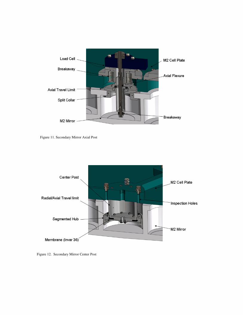
Figure 11. Secondary Mirror Axial Post
Figure 12. Secondary Mirror Center Post
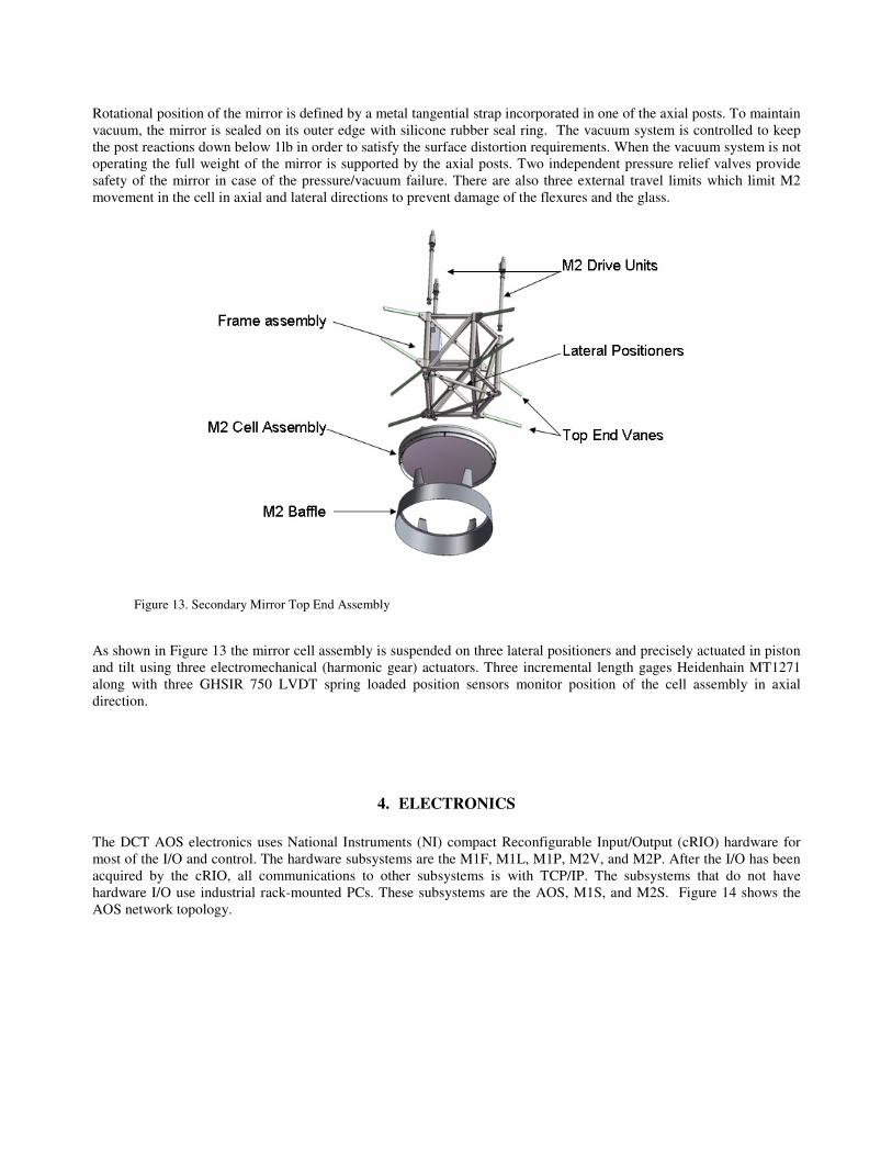
Rotational position of the mirror is defined by a metal tangential strap incorporated in one of the axial posts. To maintain
vacuum, the mirror is sealed on its outer edge with silicone rubber seal ring. The vacuum system is controlled to keep
the post reactions down below 1lb in order to satisfy the surface distortion requirements. When the vacuum system is not
operating the full weight of the mirror is supported by the axial posts. Two independent pressure relief valves provide
safety of the mirror in case of the pressure/vacuum failure. There are also three external travel limits which limit M2
movement in the cell in axial and lateral directions to prevent damage of the flexures and the glass.
As shown in Figure 13 the mirror cell assembly is suspended on three lateral positioners and precisely actuated in piston
and tilt using three electromechanical (harmonic gear) actuators. Three incremental length gages Heidenhain MT1271
along with three GHSIR 750 LVDT spring loaded position sensors monitor position of the cell assembly in axial
direction.
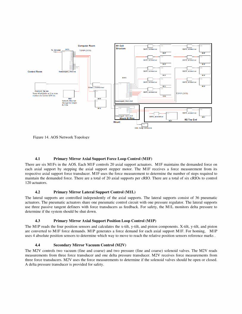
4. ELECTRONICS
The DCT AOS electronics uses National Instruments (NI) compact Reconfigurable Input/Output (cRIO) hardware for
most of the I/O and control. The hardware subsystems are the M1F, M1L, M1P, M2V, and M2P. After the I/O has been
acquired by the cRIO, all communications to other subsystems is with TCP/IP. The subsystems that do not have
hardware I/O use industrial rack-mounted PCs. These subsystems are the AOS, M1S, and M2S. Figure 14 shows the
AOS network topology.
Figure 13. Secondary Mirror Top End Assembly
4.1 Primary Mirror Axial Support Force Loop Control (M1F)
There are six M1Fs in the AOS. Each M1F controls 20 axial support actuators. M1F maintains the demanded force on
each axial support by stepping the axial support stepper motor. The M1F receives a force measurement from its
respective axial support force transducer. M1F uses the force measurement to determine the number of steps required to
maintain the demanded force. There are a total of 20 axial supports per cRIO. There are a total of six cRIOs to control
120 actuators.
4.2 Primary Mirror Lateral Support Control (M1L)
The lateral supports are controlled independently of the axial supports. The lateral supports consist of 36 pneumatic
actuators. The pneumatic actuators share one pneumatic control circuit with one pressure regulator. The lateral supports
use three passive tangent definers with force transducers as feedback. For safety, the M1L monitors delta pressure to
determine if the system should be shut down.
4.3 Primary Mirror Axial Support Position Loop Control (M1P)
The M1P reads the four position sensors and calculates the x-tilt, y-tilt, and piston components. X-tilt, y-tilt, and piston
are converted to M1F force demands. M1P generates a force demand for each axial support M1F. For homing, M1P
uses 4 absolute position sensors to determine which way to move to reach the relative position sensors reference marks .
4.4 Secondary Mirror Vacuum Control (M2V)
The M2V controls two vacuum (fine and coarse) and two pressure (fine and coarse) solenoid valves. The M2V reads
measurements from three force transducer and one delta pressure transducer. M2V receives force measurements from
three force transducers. M2V uses the force measurements to determine if the solenoid valves should be open or closed.
A delta pressure transducer is provided for safety.
Figure 14. AOS Network Topology
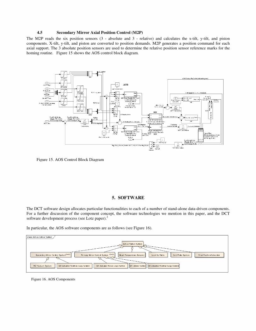
4.5 Secondary Mirror Axial Position Control (M2P)
The M2P reads the six position sensors (3 - absolute and 3 - relative) and calculates the x-tilt, y-tilt, and piston
components. X-tilt, y-tilt, and piston are converted to position demands. M2P generates a position command for each
axial support. The 3 absolute position sensors are used to determine the relative position sensor reference marks for the
homing routine. Figure 15 shows the AOS control block diagram.
5. SOFTWARE
The DCT software design allocates particular functionalities to each of a number of stand-alone data-driven components.
For a further discussion of the component concept, the software technologies we mention in this paper, and the DCT
software development process (see Lotz paper).2
In particular, the AOS software components are as follows (see Figure 16).
Figure 15. AOS Control Block Diagram
Figure 16. AOS Components
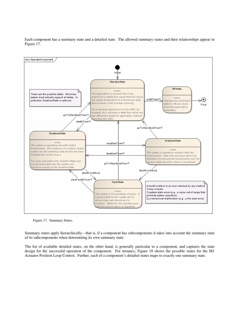
Each component has a summary state and a detailed state. The allowed summary states and their relationships appear in
Figure 17.
Summary states apply hierarchically—that is, if a component has subcomponents it takes into account the summary state
of its subcomponents when determining its own summary state.
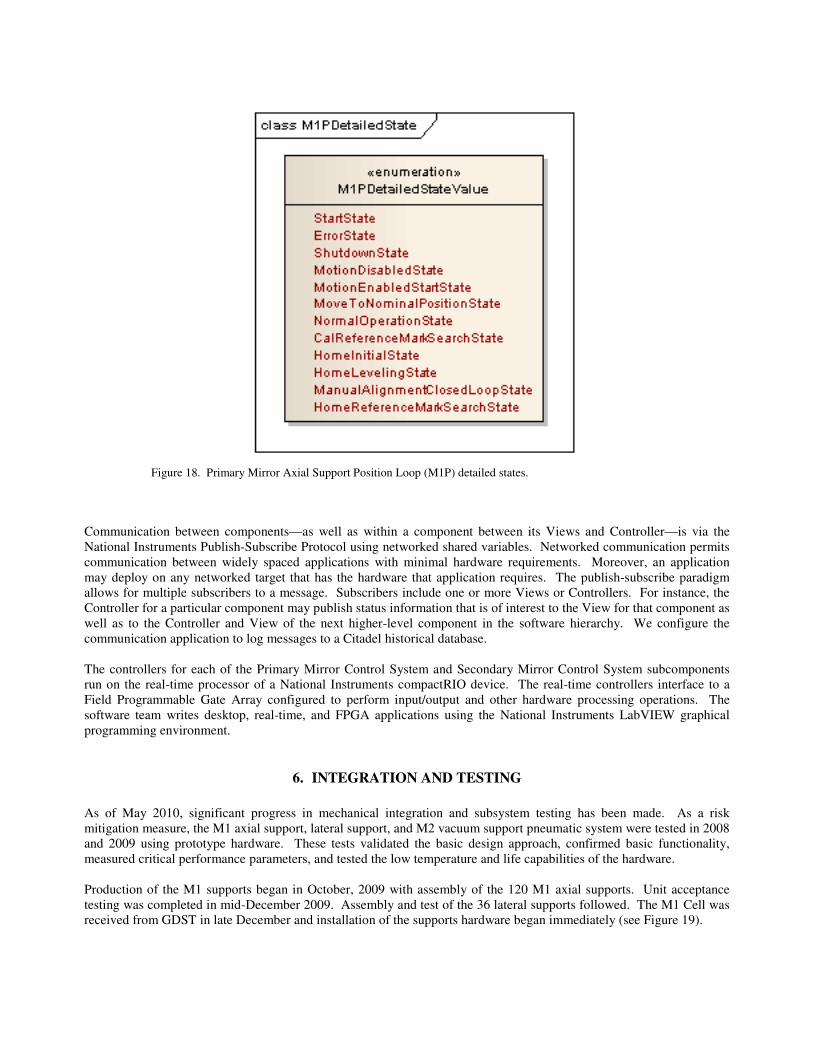
The list of available detailed states, on the other hand, is generally particular to a component, and captures the state
design for the successful operation of the component. For instance, Figure 18 shows the possible states for the M1
Actuator Position Loop Control. Further, each of a component’s detailed states maps to exactly one summary state.
Figure 17. Summary States.
Communication between components—as well as within a component between its Views and Controller—is via the
National Instruments Publish-Subscribe Protocol using networked shared variables. Networked communication permits
communication between widely spaced applications with minimal hardware requirements. Moreover, an application
may deploy on any networked target that has the hardware that application requires. The publish-subscribe paradigm
allows for multiple subscribers to a message. Subscribers include one or more Views or Controllers. For instance, the
Controller for a particular component may publish status information that is of interest to the View for that component as
well as to the Controller and View of the next higher-level component in the software hierarchy. We configure the
communication application to log messages to a Citadel historical database.
The controllers for each of the Primary Mirror Control System and Secondary Mirror Control System subcomponents
run on the real-time processor of a National Instruments compactRIO device. The real-time controllers interface to a
Field Programmable Gate Array configured to perform input/output and other hardware processing operations. The
software team writes desktop, real-time, and FPGA applications using the National Instruments LabVIEW graphical
programming environment.
6. INTEGRATION AND TESTING
As of May 2010, significant progress in mechanical integration and subsystem testing has been made. As a risk
mitigation measure, the M1 axial support, lateral support, and M2 vacuum support pneumatic system were tested in 2008
and 2009 using prototype hardware. These tests validated the basic design approach, confirmed basic functionality,
measured critical performance parameters, and tested the low temperature and life capabilities of the hardware.
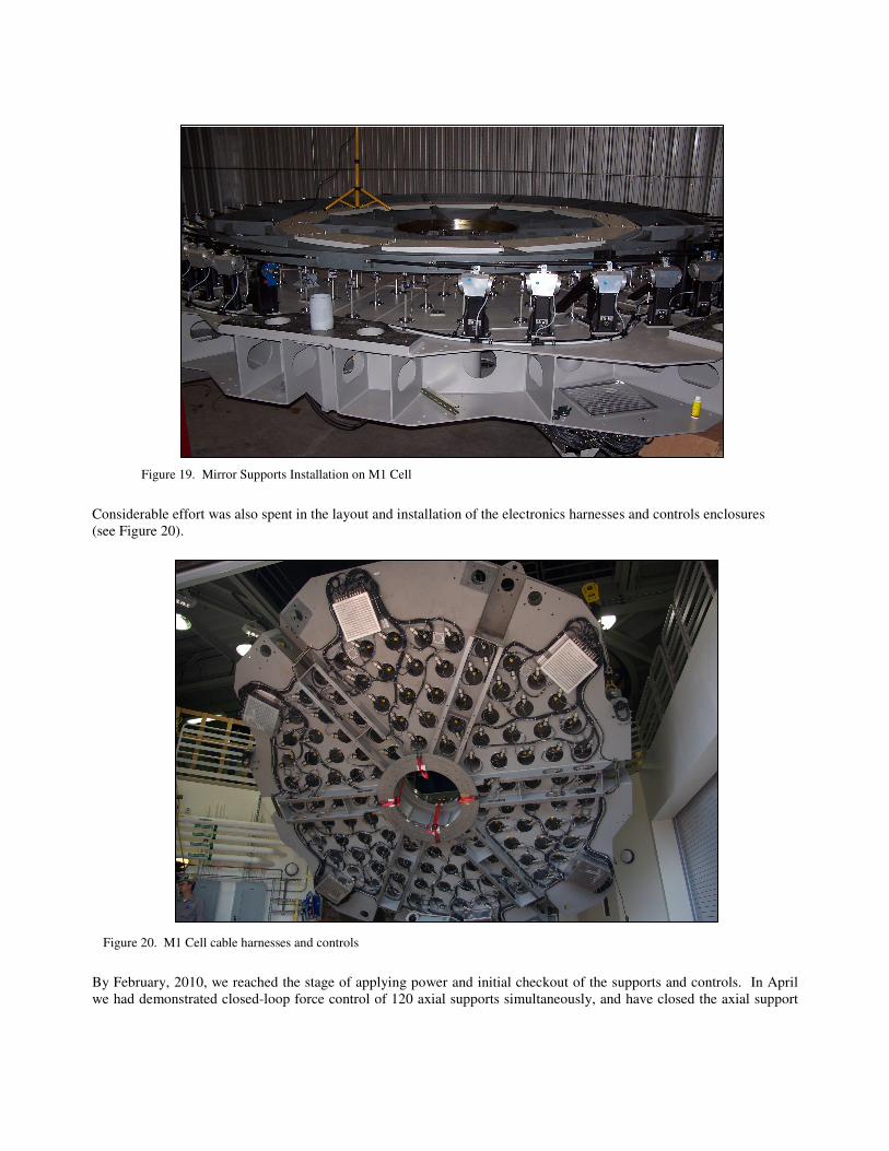
Production of the M1 supports began in October, 2009 with assembly of the 120 M1 axial supports. Unit acceptance
testing was completed in mid-December 2009. Assembly and test of the 36 lateral supports followed. The M1 Cell was
received from GDST in late December and installation of the supports hardware began immediately (see Figure 19).
Figure 18. Primary Mirror Axial Support Position Loop (M1P) detailed states.
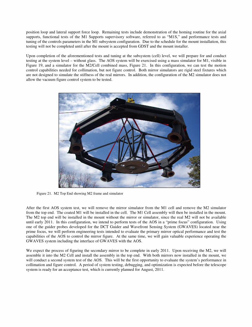
Considerable effort was also spent in the layout and installation of the electronics harnesses and controls enclosures
(see Figure 20).
By February, 2010, we reached the stage of applying power and initial checkout of the supports and controls. In April
we had demonstrated closed-loop force control of 120 axial supports simultaneously, and have closed the axial support
Figure 19. Mirror Supports Installation on M1 Cell
Figure 20. M1 Cell cable harnesses and controls
position loop and lateral support force loop. Remaining tests include demonstration of the homing routine for the axial
supports, functional tests of the M1 Supports supervisory software, referred to as “M1S,” and performance tests and
tuning of the controls parameters in the M1 subsystem configuration. Due to the schedule for the mount installation, this
testing will not be completed until after the mount is accepted from GDST and the mount installer.
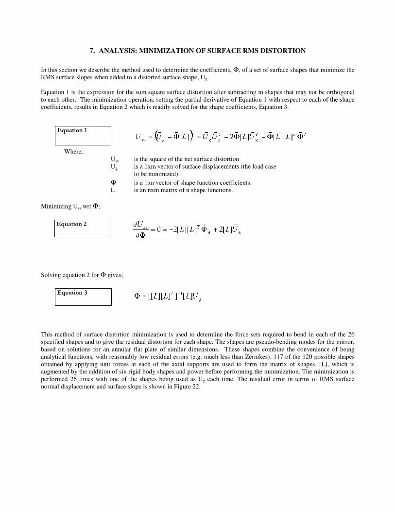
Upon completion of the aforementioned tests and tuning at the subsystem (cell) level, we will prepare for and conduct
testing at the system level – without glass. The AOS system will be exercised using a mass simulator for M1, visible in
Figure 19, and a simulator for the M2/Cell combined mass, Figure 21. In this configuration, we can test the motion
control capabilities needed for collimation, but not figure control. Both mirror simulators are rigid steel fixtures which
are not designed to simulate the stiffness of the real mirrors. In addition, the configuration of the M2 simulator does not
allow the vacuum figure control system to be tested.
After the first AOS system test, we will remove the mirror simulator from the M1 cell and remove the M2 simulator
from the top end. The coated M1 will be installed in the cell. The M1 Cell assembly will then be installed in the mount.
The M2 top end will be installed in the mount without the mirror or simulator, since the real M2 will not be available
until early 2011. In this configuration, we intend to perform tests of the AOS in a “prime focus” configuration. Using
one of the guider probes developed for the DCT Guider and Wavefront Sensing System (GWAVES) located near the
prime focus, we will perform engineering tests intended to evaluate the primary mirror optical performance and test the
capabilities of the AOS to control the mirror figure. At the same time, we will gain valuable experience operating the
GWAVES system including the interface of GWAVES with the AOS.
We expect the process of figuring the secondary mirror to be complete in early 2011. Upon receiving the M2, we will
assemble it into the M2 Cell and install the assembly in the top end. With both mirrors now installed in the mount, we
will conduct a second system test of the AOS. This will be the first opportunity to evaluate the system’s performance in
collimation and figure control. A period of system testing, debugging, and optimization is expected before the telescope
system is ready for an acceptance test, which is currently planned for August, 2011.
Figure 21. M2 Top End showing M2 frame and simulator
7. ANALYSIS: MINIMIZATION OF SURFACE RMS DISTORTION
In this section we describe the method used to determine the coefficients, Φ, of a set of surface shapes that minimize the
RMS surface slopes when added to a distorted surface shape, Ug.
Equation 1 is the expression for the sum square surface distortion after subtracting m shapes that may not be orthogonal
to each other. The minimization operation, setting the partial derivative of Equation 1 with respect to each of the shape
coefficients, results in Equation 2 which is readily solved for the shape coefficients, Equation 3.
Where:
Uss is the square of the net surface distortion
Ug is a 1xm vector of surface displacements (the load case
to be minimized).
Φ is a 1xn vector of shape function coefficients.
L is an nxm matrix of n shape functions.
Minimizing Uss wrt Φ;
Solving equation 2 for Φ gives;
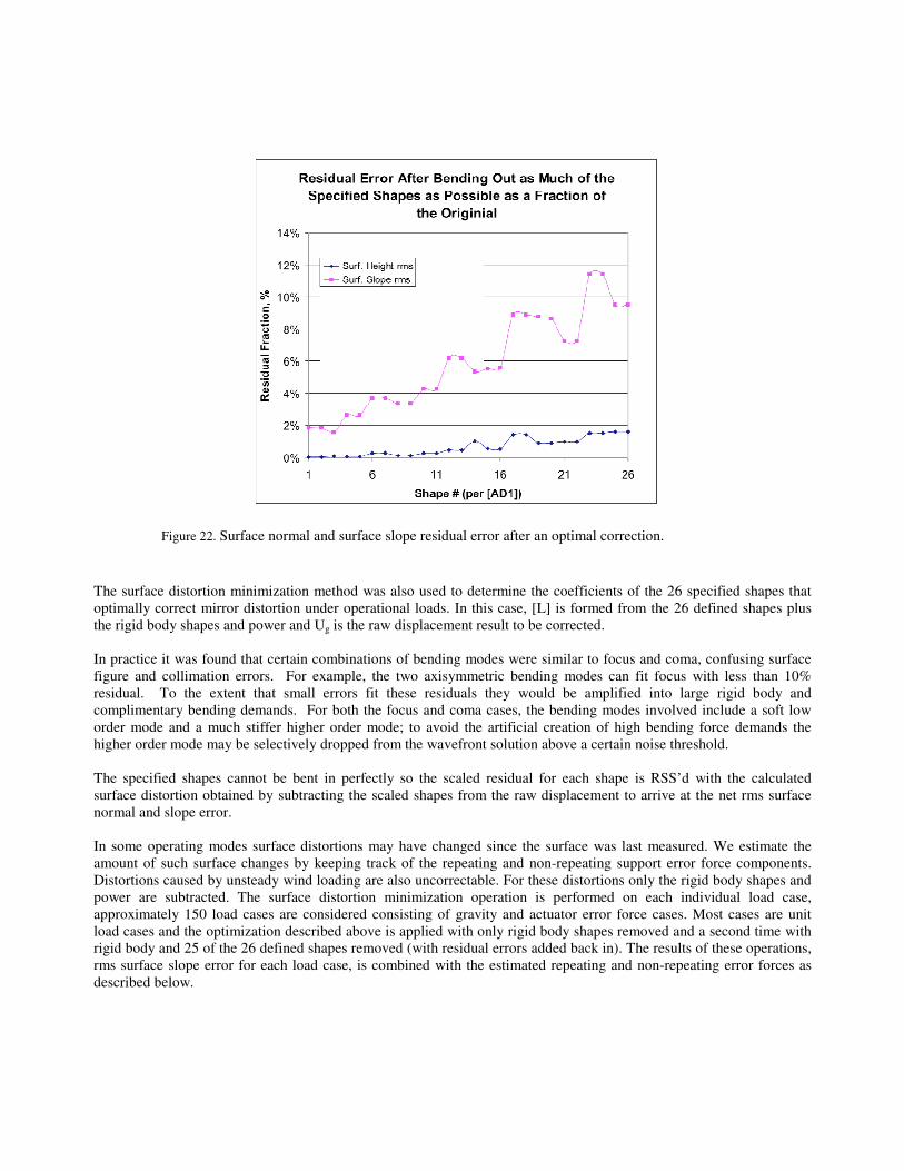
This method of surface distortion minimization is used to determine the force sets required to bend in each of the 26
specified shapes and to give the residual distortion for each shape. The shapes are pseudo-bending modes for the mirror,
based on solutions for an annular flat plate of similar dimensions. These shapes combine the convenience of being
analytical functions, with reasonably low residual errors (e.g. much less than Zernikes). 117 of the 120 possible shapes
obtained by applying unit forces at each of the axial supports are used to form the matrix of shapes, [L], which is
augmented by the addition of six rigid body shapes and power before performing the minimization. The minimization is
performed 26 times with one of the shapes being used as Ug each time. The residual error in terms of RMS surface
normal displacement and surface slope is shown in Figure 22.
Equation 1
Equation 2
Equation 3
The surface distortion minimization method was also used to determine the coefficients of the 26 specified shapes that
optimally correct mirror distortion under operational loads. In this case, [L] is formed from the 26 defined shapes plus
the rigid body shapes and power and Ug is the raw displacement result to be corrected.
In practice it was found that certain combinations of bending modes were similar to focus and coma, confusing surface
figure and collimation errors. For example, the two axisymmetric bending modes can fit focus with less than 10%
residual. To the extent that small errors fit these residuals they would be amplified into large rigid body and
complimentary bending demands. For both the focus and coma cases, the bending modes involved include a soft low
order mode and a much stiffer higher order mode; to avoid the artificial creation of high bending force demands the
higher order mode may be selectively dropped from the wavefront solution above a certain noise threshold.
The specified shapes cannot be bent in perfectly so the scaled residual for each shape is RSS’d with the calculated
surface distortion obtained by subtracting the scaled shapes from the raw displacement to arrive at the net rms surface
normal and slope error.
In some operating modes surface distortions may have changed since the surface was last measured. We estimate the
amount of such surface changes by keeping track of the repeating and non-repeating support error force components.
Distortions caused by unsteady wind loading are also uncorrectable. For these distortions only the rigid body shapes and
power are subtracted. The surface distortion minimization operation is performed on each individual load case,
approximately 150 load cases are considered consisting of gravity and actuator error force cases. Most cases are unit
load cases and the optimization described above is applied with only rigid body shapes removed and a second time with
rigid body and 25 of the 26 defined shapes removed (with residual errors added back in). The results of these operations,
rms surface slope error for each load case, is combined with the estimated repeating and non-repeating error forces as
described below.
Figure 22. Surface normal and surface slope residual error after an optimal correction.
8. CALCULATION OF NET MIRROR DISTORTION ATTRIBUTABLE
TO THE SUPPORT SYSTEM
The performance analysis for the primary mirror support follows a similar process to that of the LSST mirror supports3.
The analysis considers the effect of force and moment errors at every attachment point to the mirror, and the
correctability of those errors, either by calibration in open-loop mode or by wavefront sensing based feedback in closed-
loop mode.
8.1 Support force errors
Support force errors are the difference from the intended value of any of the six force components (Fx, Fy, Fz, Mx, My
and Mz) possible at an actuator interface point on the mirror. Error forces result from misalignment and from frictional
or elastic effects. Misalignment and elastic error forces will not change over time so the distortion they produce can be
measured and corrected. This is less likely to be true of frictional error forces. We categorize error forces that do not
change unpredictably between distortion measurement and corrections as repeating error forces. Those that might change
between measurements are categorized as non-repeating error forces. The effects of repeating error forces can be
partially corrected by the AOS system.
The repeating and non-repeating error forces for the primary axial and lateral support actuators have been estimated and
prototypes have been tested to validate the actuator design. The lateral support actuators are not involved in the active
correction of distortion, this task is left to the 120 axial support actuators. Forces in the lateral system are adjusted to
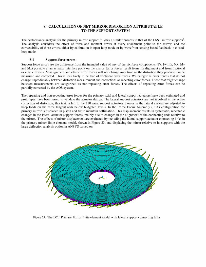
keep loads on the three tangent rods below budgeted levels. In the Prime Focus Assembly (PFA) configuration the
primary mirror is displaced in piston and tilt to maintain collimation. This displacement results in systematic, repeatable
changes in the lateral actuator support forces, mainly due to changes in the alignment of the connecting rods relative to
the mirror. The effects of mirror displacement are evaluated by including the lateral support actuator connecting links in
the primary mirror finite element model, shown in Figure 23, and displacing the mirror relative to its supports with the
large deflection analysis option in ANSYS turned on.
Figure 23. The DCT Primary Mirror finite element model with lateral support connecting links.
8.2 Randomly distributed support force errors
A random distribution of support force errors will generally be less damaging than a distribution that has a low order
spatial distribution. We use the full actuator error force, repeating and non-repeating, in estimating the effect of
randomly distributed force errors (we use a fraction of the error force in evaluating the effect of systematically
distributed error forces with the fraction determined by a Monte Carlo Analysis).
Random support force errors are evaluated by sampling the effects at one location and using those results at all similar
locations. The RMS slope error for the 36 axial actuators in the outer row caused by one of the error force components is
simply √36 * the RMS slope error caused by the error force applied to one of these locations.
In most cases the applied error force is reacted by the kinematic constraints applied to the finite element model. Axial
force errors are reacted by distributed axial forces at all actuators to mimic the response of the mirror support control
system.
8.3 Systematically distributed support force errors
These are sets of forces acting on the mirror that are correlated in some way. Examples are forces that result from or are
altered by differential thermal growth or a displacement of the mirror relative to the supports. These effects tend to
produce force sets that have net radial, lateral or astigmatic components. Force sets that generate the low order flexural
modes of the mirror can yield deflections that are much larger than would be predicted using the random support force
analysis procedure above. Random chance can also result in error force distributions that result in low order distortions
such as astigmatism. This effect is evaluated by performing a Monte Carlo analysis in which 100 sets of error forces are
randomly assigned and each resulting force set is evaluated to determine how much of a low order distribution of force it
contains.
Axial error forces make the largest contribution to distortion so attention will be confined to this component, including
the axial error component from the lateral support actuators. It is assumed that the systematic distribution can be
expressed as a linear combination of normalized force sets given by the bending mode polynomials evaluated at the
actuator locations. These force sets are applied to the finite element model and RMS surface slopes are computed. The
scaling factor to apply to each of these load cases has been calculated by generating 100 sets of randomly selected
actuator forces and evaluating the coefficients for the Zernike components of each set. The standard deviation (⌠) of
these coefficients gives the value that will not be exceeded 68% of the time, the average value is near zero as would be
expected. In the case of the primary with 120 actuators, the standard deviation of the astigmatic force coefficient is 13%
of the RMS value of the actuator force error. The standard deviations of the coefficients for other low order distributions
are similar in magnitude. It is assumed that the 1⌠ force coefficient applies to each term simultaneously.
8.4 Repeating and non-repeating support force errors
As noted above, the finite element load cases were processed twice removing only rigid body shapes representing the
effect of non-repeating error forces and removing also 25 defined shapes representing the effect of the repeating
component of error force. We have also noted that we estimate the magnitudes of both the repeating and non-repeating
error forces. We then compute the effect of repeating and non-repeating error forces and RSS the result together to
obtain the net effect. Note that we could obtain the same result by applying the estimated error forces as the actual input
to the finite element model. This would require separate load cases for the repeating and non-repeating error force
magnitudes and a re-run whenever the force estimates were revised, a frequent occurrence since the support system
design is refined in response to the analysis results.
8.5 Totaling the effects of all error sources
Gravity, random and non-random structure function errors are combined by RSS'ing all results of. Specifically:
Where: Total is the net RMS slope error from the support system
g is the RMS slope error for gravity at a particular elevation angle.
Random is the net random error force slope error
AB,etc are the non-random cases
This equation applies equally to the RMS surface distortion.
8.6 Results
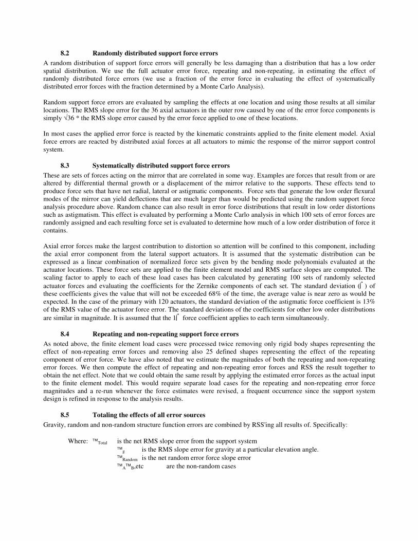
Predicted results in terms of primary surface slope error as a function of elevation angle when primary wavefront
measurements are not available are shown in Figure 24. Although surface wavefront measurements are not available, the
AOS can still make corrections for certain elevation angle dependent effects such as misalignment. Axial force
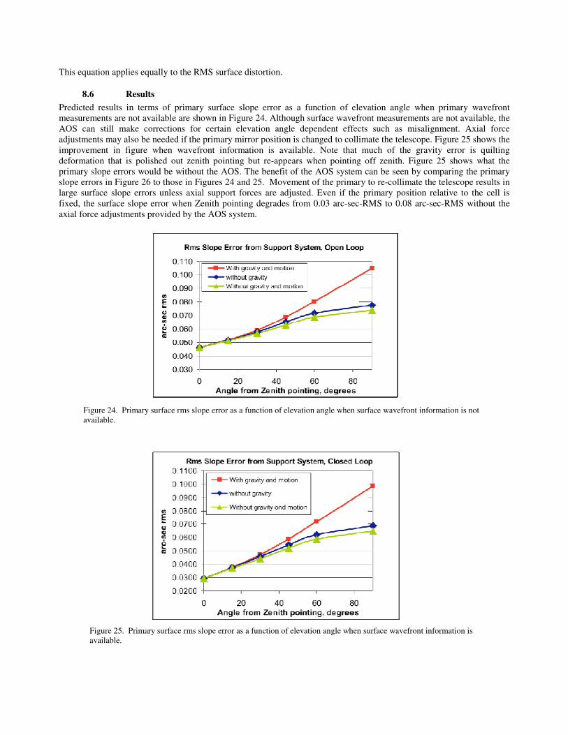
adjustments may also be needed if the primary mirror position is changed to collimate the telescope. Figure 25 shows the
improvement in figure when wavefront information is available. Note that much of the gravity error is quilting
deformation that is polished out zenith pointing but re-appears when pointing off zenith. Figure 25 shows what the
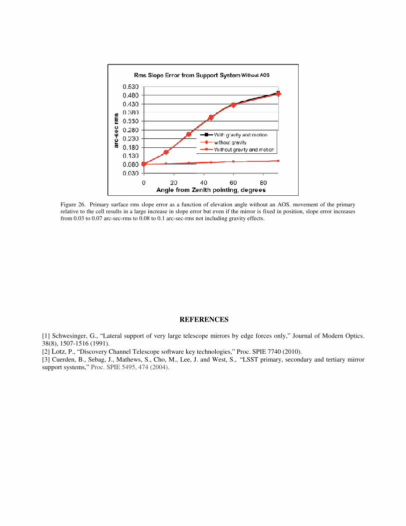
primary slope errors would be without the AOS. The benefit of the AOS system can be seen by comparing the primary
slope errors in Figure 26 to those in Figures 24 and 25. Movement of the primary to re-collimate the telescope results in
large surface slope errors unless axial support forces are adjusted. Even if the primary position relative to the cell is
fixed, the surface slope error when Zenith pointing degrades from 0.03 arc-sec-RMS to 0.08 arc-sec-RMS without the
axial force adjustments provided by the AOS system.
Figure 25. Primary surface rms slope error as a function of elevation angle when surface wavefront information is
available.
Figure 24. Primary surface rms slope error as a function of elevation angle when surface wavefront information is not
available.
REFERENCES [1] Schwesinger, G., “Lateral support of very large telescope mirrors by edge forces only,” Journal of Modern Optics.
38(8), 1507-1516 (1991).
[2] Lotz, P., “Discovery Channel Telescope software key technologies,” Proc. SPIE 7740 (2010). [3] Cuerden, B., Sebag, J., Mathews, S., Cho, M., Lee, J. and West, S., “LSST primary, secondary and tertiary mirror
support systems,” Proc. SPIE 5495, 474 (2004).
Figure 26. Primary surface rms slope error as a function of elevation angle without an AOS. movement of the primary
relative to the cell results in a large increase in slope error but even if the mirror is fixed in position, slope error increases
from 0.03 to 0.07 arc-sec-rms to 0.08 to 0.1 arc-sec-rms not including gravity effects.