The ABC’s of DRO’s - Automation and Metrology · The ABC’s of DRO’s An Introduction to...
21
The ABC’s of DRO’s An Introduction to Measuring Systems Readout Systems CNC Control Systems Precision Glass Scales
-
Upload
duongkhuong -
Category
Documents
-
view
223 -
download
0
Transcript of The ABC’s of DRO’s - Automation and Metrology · The ABC’s of DRO’s An Introduction to...

The
ABC’s
of
DRO’s
An Introduction toMeasuring Systems
Readout SystemsCNC Control Systems
Precision Glass Scales

INTRODUCTION TO READOUT SYSTEMS
2
TABLE OF CONTENTS
INTRODUCTION . . . . . . . . . . . . . . . . . . . . . . . . . . . . . . . . . . . .3
WHAT IS A DRO AND HOW DOES IT WORK . . . . . . . . . . . .3
PRECISION GLASS SCALE . . . . . . . . . . . . . . . . . . . . . . . . . . .4
DRO and VRO . . . . . . . . . . . . . . . . . . . . . . . . . . . . . . . . . . . . . .5
WHY THEY ARE USED . . . . . . . . . . . . . . . . . . . . . . . . . . . . . .6
FYI: How Machine Tool Errors Occur . . . . . . . . . . . . . . . . . . . . .7
THE ECONOMICS OF READOUT SYSTEMS . . . . . . . . . . . . .8
HOW AND WHERE THEY ARE USED . . . . . . . . . . . . . . . . .10
GLOSSARY . . . . . . . . . . . . . . . . . . . . . . . . . . . . . . . . . . . . . . .13
TEST YOUR KNOWLEDGE . . . . . . . . . . . . . . . . . . . . . . . . . .19
APPLICATION FOR RECOGNITION OF COMPLETION . . .22
Authored by:
Robb JonesPaula SopakJohn Parker
Robert RothlederMitchell D. Klein
INTRODUCTION TO READOUT SYSTEMS
3
Introduction
AACU-RITE readouts are application-specific systems for the manual machine tool industry.The primary benefit is saving time and increased productivity. The addition of a readout systemon any machine allows for reduced scrap due to the elimination of measuring inaccuracies.Machine operators are relieved of tedious setup, positioning and checking operations so moretime is spent machining. Training is easier and faster, elevating less-experienced operators toobtain optimum production levels in a shorter time. The return on investment (ROI) on savingsaverages less than 30 days.
What is a DRO and How Does It Work
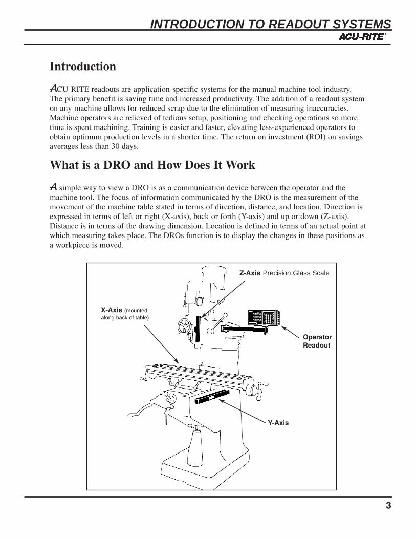
AA simple way to view a DRO is as a communication device between the operator and themachine tool. The focus of information communicated by the DRO is the measurement of themovement of the machine table stated in terms of direction, distance, and location. Direction isexpressed in terms of left or right (X-axis), back or forth (Y-axis) and up or down (Z-axis).Distance is in terms of the drawing dimension. Location is defined in terms of an actual point atwhich measuring takes place. The DROs function is to display the changes in these positions asa workpiece is moved.
Z-Axis Precision Glass Scale
Y-Axis
X-Axis (mountedalong back of table)
OperatorReadout
INTRODUCTION TO READOUT SYSTEMS
4
Precision Glass Scale
AACU-RITE manufactures application-specific readout systems for the manual machine toolindustry. Each readout system includes a DRO 100, DRO 200 or VRO 300, a minimum of oneprecision glass scale and associated hardware used in the mounting of the readout and precisionglass scale(s).
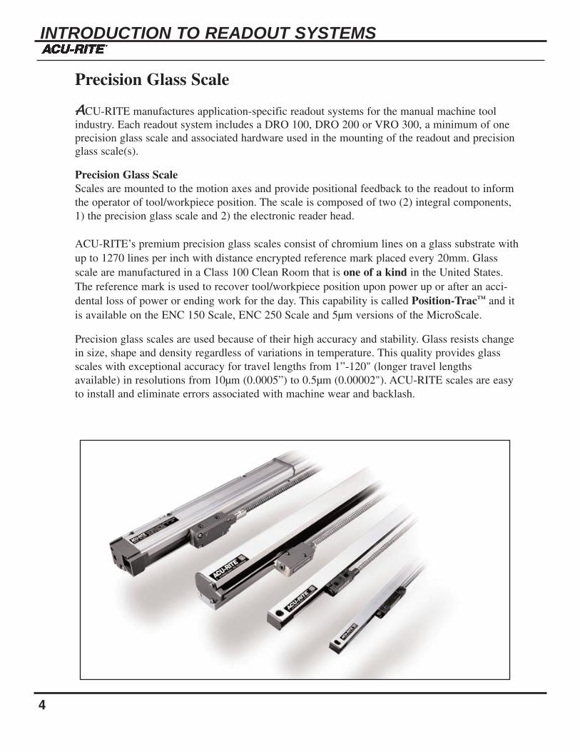
Precision Glass ScaleScales are mounted to the motion axes and provide positional feedback to the readout to informthe operator of tool/workpiece position. The scale is composed of two (2) integral components,1) the precision glass scale and 2) the electronic reader head.
ACU-RITE’s premium precision glass scales consist of chromium lines on a glass substrate withup to 1270 lines per inch with distance encrypted reference mark placed every 20mm. Glassscale are manufactured in a Class 100 Clean Room that is one of a kind in the United States.The reference mark is used to recover tool/workpiece position upon power up or after an acci-dental loss of power or ending work for the day. This capability is called Position-Trac™ and itis available on the ENC 150 Scale, ENC 250 Scale and 5µm versions of the MicroScale.
Precision glass scales are used because of their high accuracy and stability. Glass resists changein size, shape and density regardless of variations in temperature. This quality provides glassscales with exceptional accuracy for travel lengths from 1”-120" (longer travel lengths available) in resolutions from 10µm (0.0005”) to 0.5µm (0.00002"). ACU-RITE scales are easyto install and eliminate errors associated with machine wear and backlash.

INTRODUCTION TO READOUT SYSTEMS
21
10. What benefit(s) do Precision Glass Scale(s) provide?
a. High accuracy and stability.b. Easy to install.c. Eliminates backlash or wear of the machine tool.d. All of the above
11. The Vision Readout has which additional features?
a. 9-inch CRT.b. 1 to 6 axes of motion can be displayed.c. Programming capabilities.d. Built-in assistance, reference tables & calculators.e. All of the above
12. Call ACU-RITE at 1-800-344-2311 and record the name and telephone number of yourACU-RITE territory manager.
Name_________________________________________Phone Number____-____-_________

INTRODUCTION TO READOUT SYSTEMS
20
5. X-axis travel in a milling application is defined as?
a. The plane of movement on a machine table whose directions are either back or forward and horizontal to the floor.
b. The plane of movement on a machine table whose directions are either left or right and horizontal to the floor.
c. The plane of movement on a machine table whose directions are either up or down and perpendicular to the floor.
6. The Position Trac™ feature of the ACU-RITE ENC 150 Precision Glass Scale is?
a. A pattern on the scale glass that is read by the reader head to reset the readout to zero.
b. A term used to describe the movement of the machine table or tool.c. A feature of the readout system that allows rapid recovery of position after a power
loss.
7. Why would you retrofit a machine tool with ACU-RITE Readout Systems?
a. Reduce operating expensesb. Increase profitsc. Reduce or eliminate scrapd. Increase operator performance and reduce fatiguee. All of the above
8. A Reader Head is defined as?
a. A scale mounted to the motion axes.b. Chromium lines on a glass substrate and manufactured in a Class 100 Clean Room.c. A photoelectric device that is used to convert the line pattern on the glass scale to a
digital signal.d. All of the above.
9. Accuracy is defined as?
a. The degree to which it is possible to make linear measurements correctly with respect to a known standard.
b. The smallest unit of motion that a readout system is capable of measuring and displaying.
c. Movement of the machine table or tool.

INTRODUCTION TO READOUT SYSTEMS
5
DRO and VROAAs mentioned earlier ACU-RITE readout systems are designed for four (4) application areas.
Digital Readout (DRO) - a DRO is a digital display console that is used as an interfacebetween the machine operator and tool/workpiece position. The following are basic featuresfound on a DRO:
• Die-cast metal enclosure.• Sealed, 3-D, tactile feel, color keypad.• Absolute/Incremental display.• Preset and zero reset capability.• Near-zero warning• Inch to Millimeter display.• Linear error compensation for machine tool inaccuracies.• 14-Segment Vacuum Fluorescent Display.
Vision Readout (VRO) - The VRO is distinguished from the DRO by these features:
• Programming capabilities with pre-programmed milling and drilling routines.• The display on the VRO is a 9-inch CRT.• Built-in assistance, reference tables and calculator. • Saves part programs for future recall.
DRO 100 Grinding and General Purpose applications
DRO 200 Milling, Turning,EDMing, Grinding and GeneralPurpose applications
MICRO-LINE Milling and Turningapplications
VRO 300 Milling and Turningapplications

Why They Are UsedWith the greater positioning accuracy of the system, the inherentaccuracy of the machine tool is used to full advantage.Therefore, the likelihood of producing scrap parts is greatlyreduced. The time the operator used to spend setting the coordi-nates for positioning is now spent machining more parts. Thistranslates, into greater operator efficiency and, in turn, increasedproductivity. The results are savings in operating expenses andtherefore a more profitable shop.
Aside from the elimination of positioning problems, there areother operator-oriented benefits. For example, there is no longera need to do paper-and-pencil calculations for offsets or otherdimensions that may not appear on the drawing since exactpositioning is displayed on the DRO.
Another is the reduction in operator fatigue associated withcounting hand wheel turns and straining to read verniers, a fac-tor that frequently affects operator performance and satisfaction.
Lastly, a digital measuring system makes training of new orless-experienced operators much easier and less time consum-ing.
6
INTRODUCTION TO READOUT SYSTEMS

INTRODUCTION TO READOUT SYSTEMS
19
Test Your KnowledgeThis test will evaluate your basic knowledge of ACU-RITE Readout Systems and more impor-tantly help you begin to identify where ACU-RITE Readout Systems can be used. Upon com-pletion of this test please attach it along with the completed application and return it to receivea free ACU-RITE shirt.
Circle the most “accurate” answer.
1. A readout system includes which of the following?
a. Machine tool and workpieceb. Computerc. Readout, scale and mounting hardwared. All of the above
2. ACU-RITE Systems can be retrofitted to what type of metalworking machines?
a. Grindingb. EDMsc. Millingd. Turninge. All of the abovef. None of the above
3. Resolution is defined as?
a. The degree to which it is possible to make linear measurements correctly with respect to a known standard
b. The smallest unit of motion that a readout system is capable of measuring anddisplaying
c. Movement of the machine table or toold. All of the above
4. ACU-RITE Precision Glass Scales are available in what resolution(s)?
a. 10µm (0.0005") and 5µm (0.0002")b. 1" to 120"c. 2µm (0.0001"), 1µm (0.00005") and 0.5µm(0.00002")d. A and C abovee. None of the above

INTRODUCTION TO READOUT SYSTEMS
18
X-AxisUsually the plane of movement on a machine table whose direction is either left (+) or right (-)and horizontal to the floor.
Y-AxisUsually the plane of movement on a machine table whose direction is either back (+) or forth (-)and horizontal to the floor.
Z-AxisUsually the plane of movement on a machine table whose direction is either up (+) or down (-)and perpendicular to the floor.
Note: On a lathe the x-axis is the diameter (cross slide) and the z-axis is the longitu-dinal. When lathe parts are inspected they are setup vertically and therefore, the length becomes the height and the diameter is checked horizontally.
Zero ReferenceThe point selected on or near the workpiece from which positioning is started or, in some cases,referenced for the entire machining operation. (Also see Datum and Absolute Measurement.)
Zero ResetAutomatic or manual zeroing of the measurement (or count) displayed on the DRO. (Anotherterm for Reset.)

INTRODUCTION TO READOUT SYSTEMS
7
FYI: How Machine Tool Errors Occur
It is common knowledge that all machine tools - new and old - contain some error in the accu-racy of moving components when compared to a standard that is known to be true. This area ofconcern is important enough for you to learn more about these errors and why they occur.
In every machining operation, there is always some degree of error or inaccuracy due to at leastone of the following machine tool deficiencies:
a) Gravity causes deflections in the machine tool structure, particularly when a heavy workpiece is placed on a machine with overhanging table or ways. A result of these deflections is commonly called Abbe error. (The following paragraphs provide fur-ther explanation.)
b) The fit between mating surfaces is loose, because of manufacturing tolerances, subse-quent wear, or improper gib adjustment.
c) The ways are not scraped straight or are not aligned perfectly at assembly.d) Driving and cutting forces cause deflections, since no material is totally rigid.e) Temperature variations can distort machine geometry.
In addition, machine tables and ways can be forced out of alignment if you use the locksimproperly. Tables that are not completely locked in position will shift from the forces ofmachining and eventually wear.
Abbe error (also called machine geometry or transfer error) is a progressive fault occurringmainly in machine tool tables or beds. It occurs in other moving parts also, but we'll limit ourdiscussion here to mill tables. Gibs and table ways can wear due to an increase in pressure atthe edge of the machine way, on both the knee and center of the table. This causes increasedwear at these points as the center of gravity of the table moves with an increasing overhang.
The shift of weight is gradual as the table moves from center; therefore the wear is also gradual.The result is the formation of an arc shape along the table and knee, concave to the ways.Pressure of the gib against the way causes the gib to wear. Often when a short travel is used, re-tightening the gib causes localized wear of the way.
The scale attached to the table measures its horizontal motion with respect to the fixed readinghead. A worn table, however, follows the curvature of the arc, resulting in an error in the move-ment of the workpiece relative to the cutter. In the case of the milling machine, the workpiece ismoving too far.
ACU-RITE readout systems include automatic linear error calculation and stored error compen-sation factors in all systems as a standard feature. Linear error compensation can be entered assingular or with up to (99) ninety-nine segments per scale travel length. Error compensationcorrections of up to ±9999 ppm (parts per million) can be entered.

8
INTRODUCTION TO READOUT SYSTEMS
The Economics of Readout Systems
When it comes to seeing the actual benefits of adding a readout to a manual machine tool often themost convincing argument is the rise in productivity due to increased utilization, output and accura-cy. Jobs that might have been vended out due to a lack of time and capability can be kept in-housewith a readout system. Similarly, jobs that were turned down or quoted too high in the past can behandled due to the increased capability of the shop.
Profit Centers are what some shop managers call machines retrofitted with readouts. Others saytheir DROs “paid for themselves in just 90 days in reduced scrap alone. Everything saved now ispure additional profit!”
It is easy to spout praises once a readout systems working for you, but how do you help the potien-tial buyer justify the need to make that first purchase? There are at least two methods you can useto figure out the potential gains. One is the annual dollar savings method; the other is the purchasepayback method. Both can be represented by mathematical formulas.
Calculating Annual Savings
S = HNC (Td-Tr)60
Where:S = the annual savingsH = the number of working hours per yearN = the average number of moves per hourC = the cost per hour of operator
Td = the indexing time in minutes using dials or rodsTr = the indexing time with digital readout
Lets assume that your machine operator works 2000 hours a year (H) and makes an average of sixmoves each hour (N). You pay the operator an hourly wage of $10.00 (C). He “eyeballs” his movesat an average of 2.75 minutes per move (Td), or uses a DRO, averaging 1 minute each move (Tr).When these values are inserted into the formula, the result is persuasive:
S = 2000 x 6 x 10 (2.75 - 1.00)60
S = $3,500(per DRO/operator)
As you can see, the reduced time (or increased speed) for the job with a DRO-equipped machine isenough by itself to warrant the purchase (averaging $1500). A shop working two or three shifts willincrease its relative number of moves proportionately, and yield savings significantly above our$3500 example.

INTRODUCTION TO READOUT SYSTEMS
17
Reader HeadA photo-electric device that is used to convert the line pattern on the glass scale to a digitalsignal that is the input to the readout to display tool/workpiece position.
Reference MarkThis is a pattern on the glass scale that is sensed by the reader head and is used for the Position-Trac™ feature or to quickly reset the readout system to zero.
RepeatabilityThis is the capability of the scale to return to an identified position within the specified toler-ance. A repeatable scale is one that begins at zero on both an indicator and readout system.Then the table or tool is moved away from zero on both the indicator and readout system.When the table or tool is returned, both the indicator and readout system should again readzero. If this operation can be performed numerous times within a specified tolerance, the read-out system and machine are judged to be repeatable.
ResolutionThis is the smallest unit of motion that a readout system is capable of measuring and display-ing. ACU-RITE readout systems are accurate up to 0.00002" or 0.5 micron.
Scale AssemblyConsists of a glass scale enclosed in aluminum housing with sealed, die-cast metal end caps. Toenhance glass scale durability, it is further protected from the environment by a recessed highlychemical-resistant, interlocking lip seal.
SystemA digital measuring system includes the DRO and one scale for each measured axis of move-ment, plus electrical connections and any necessary mounting bracketry.
TravelTerm used to describe the movement of the machine table or tool.
Vision Readout (VRO)The readout portion of the VRO System is composed of an easy to view 9-inch CRT displayand a sealed, 3D tactile-feel color keypad, built-in assistance, reference tables & calculators.
WorkpieceThe material or part from which the finished part is machined. (Also, the finished part.)

INTRODUCTION TO READOUT SYSTEMS
16
Micron (µm)1 micron is equal to .001mm or .00005".
MicroprocessorThe solid-state electronic "heart" of a programmable DRO, it interacts with the program andstorage memories and the input/output electronics of a DRO's computer.
OffsetRefers to the radius or diameter of a round cutting tool by which a dimension is modified inorder not to over cut or under cut the required dimension.
PointA location on a workpiece drawing corresponding to either a termination of a dimension or thecenter point of a hole. Except for the zero reference (start) point, all other points involve amachining operation and are called either reference points (tool moves from) or target points(tool moves to).
Position-Trac™A feature of the readout system that allows rapid recovery of position once power has beenrestored to the system after shutdown or accidental loss of power.
Power RecoveryA lighted message on a DRO display signifying a power interruption or a previous "power-off"condition.
PrecisionThe closeness (or tolerance) of agreement among repeated measurements of the same character-istic, by the same method, under the same conditions.
PresetMost digital readouts have this feature, which permits presetting (entering) the machiningdimension and machining to zero. It also permits presetting a tool offset that is automaticallycalculated into the dimension.
ProgramA sequence of instructions entered into the memory of a programmable readout and retrieved ina predetermined fashion to be used for machining operations or auxiliary functions. Also thelayout and entry of these instructions.
QuadratureA sine or square-wave signal whose phase differs by 90° with respect to a base signal. Thequadrature signal is necessary for bi-directional counting.

Calculating Payback
When you install a digital measuring system on most machine tools, you can expect an annualreturn of at least 500% on your investment. The exact return in both dollars and time depends, ofcourse on the type of machine and its usage. Below is a basic formula which you can use for justifi-cation of a purchase.
Pay back time = I ABC
Where:I = Dollars investedA = Machine revenue in $/hourB = Hours per day workedC = Productivity increase in %
Putting this formula to work is simple. We’ll use an investment figure (I) of $1600, the cost ofinstalling an average system on a small mill. Using a machine revenue rate of $20 per hour (A) foran 8-hour day (B) we can assume a typically conservative increase of 25% in productivity (C).When these figures are plugged into the formula, the result is:
PBT = 1600 = 160020 x 8 x .25 40
PBT = 40 days to pay for system
Where:PBT = Pay back time
If your shop operates 52 weeks a year, the annual return will be 6.5 times your investment (5.5times after payback) or $8,800 the first year.
Moreover, a machine utilization of three shifts per day will produce a proportionately greater return.Well worth the investment.
INTRODUCTION TO READOUT SYSTEMS
9

INTRODUCTION TO READOUT SYSTEMS
10
How and Where They Are Used
The following machine tools represent typical applications for ACU-RITE’s readout systems:
Milling - Mills, vertical boring mills and universal horizontal/vertical mills. Most system retrofits willrequire either a MICRO-LINE, DRO 200M, VRO 300M or a MILLPWR with a minimum of twoencoders. An optional 3rd scale for the Z-axis can be used (don't forget that the VRO 300M can accom-modate up to six machine tool axes).
Standard Mill Boring Mill
Jig Borers
INTRODUCTION TO READOUT SYSTEMS
15
Glass ScaleA precisely ruled length of glass substrate, on which a uniformly spaced pattern of chrome linesis deposited, which allows light to pass through intermittently for the purpose of measurement.The patterned glass functions in combination with an index grating (to form a fringe pattern)and a photoelectric sensor to generate signals to the DRO.
Scale (Linear)A scale is composed of the precision glass scale (1" to 120" in length, longer lengths are available in multi-sections) and a reader head. The reader head contains the electronics to sense the movement of the glass scale and converts this motion into a digital signal that is detected by the readout and displayed as the distance moved.
Scale (Rotary)Functionally the same as a scale except that it uses an optical disk rather than a scale andit usually mounts directly to the lead screw instead of the table. (Also, measured in radius/diameter and degrees.)
Note: This mounting configuration will not compensate for lead screw backlash or machine wear.
Inch-to-Metric ConversionA switch feature on many DROs that permits instant conversion of measurement and displayfrom inches to millimeters and vice versa.
Incremental MeasurementA measurement between two successive points on a workpiece, usually with a DRO system,incremental (point-to-point) positioning is done from a displayed preset dimension to zero, orfrom zero to the dimension, then the display is reset to zero.
Light-Emitting Diode (LED)A solid-state electronic component used in DROs, both as light sources in the reading head andas digital display elements.
Linear MeasurementA straight-line distance traversed and measured by a transducer attached to the machine in theaxis of movement.
MetrologyMetrology is the science and technology of precision measurements.

INTRODUCTION TO READOUT SYSTEMS
14
Conversion: Metric to English25.4mm = 1 inch1mm = .03973"0.01mm (10µm) = .00039"5µm = .0002"2µm = .0001"1µm = .00005"0.5µm = .00002"Note: 1 micron is equal to .001mm
Coordinate (system)A system of axes. (See "Axis.")
CounterAlternate name for DRO, normally used to imply that the instrument adds or subtracts incre-mental measurements of motion; therefore, "counts."
Cutter OffsetRefers to the radius or diameter of a cutting tool (drill, mill, reamer, etc.) that is added to orsubtracted from the dimension used to machine the workpiece.
Datum (point)Usually applied to any reference point from which measurements are taken for machiningmotions and operations. Also, known as machine zero and/or workpiece zero.
Digital Readout (DRO)The readout portion of the DRO System. Composed of either a CRT or vacuum fluorescent dis-play and a sealed, 3D tactile-feel color keypad. (The words Console and Counter are also usedas alternate names for DROs.)
DimensionA specific measure of distance between two points or planes (based on linear movement along agiven axis).
INTRODUCTION TO READOUT SYSTEMS
11
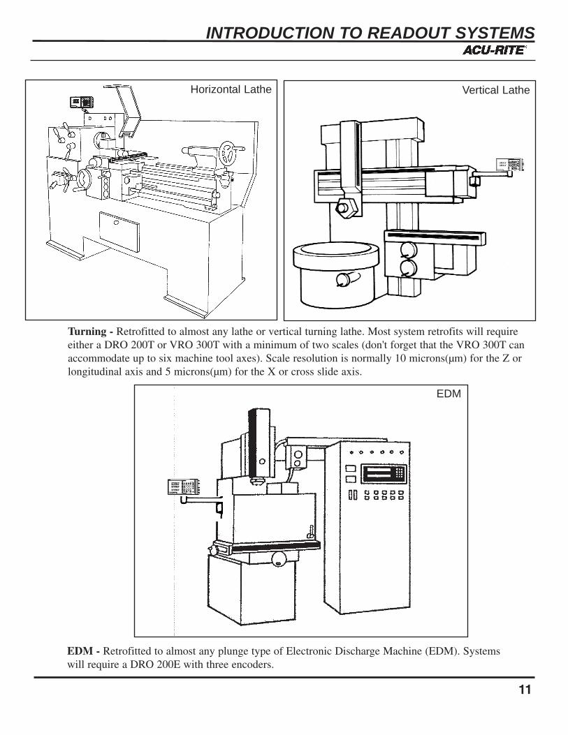
Turning - Retrofitted to almost any lathe or vertical turning lathe. Most system retrofits will requireeither a DRO 200T or VRO 300T with a minimum of two scales (don't forget that the VRO 300T canaccommodate up to six machine tool axes). Scale resolution is normally 10 microns(µm) for the Z orlongitudinal axis and 5 microns(µm) for the X or cross slide axis.
EDM - Retrofitted to almost any plunge type of Electronic Discharge Machine (EDM). Systemswill require a DRO 200E with three encoders.
Horizontal Lathe Vertical Lathe
EDM

INTRODUCTION TO READOUT SYSTEMS
Grinding - Retrofitted to almost any surface grinder. Most system retrofits will require either a DRO 100or DRO 200G with a minimum of one scale. Scale resolution is normally 2 microns(µm).
Grinder
12
Optical Comparator - Restores the linear accuracy of comparator; eliminates dependence on accuracyof ball screw drives with inherent backlash. ACU-RITE’s Digital Readouts enhance coordinate measur-ing immensely and effect great savings in both time and accuracy. They require either a DRO 100 or200G with a minimum of two encoders. (2µm for 2 axes.)
OpticalComparator

INTRODUCTION TO READOUT SYSTEMS
13
Glossary
This is a glossary of common terms used with digital measuring systems. Use this glossary tobecome more familiar with DRO terminology and keep it for future reference.
Abbe error1. The easiest explanation for DRO purposes is: A measurement error due to the
nonparallel motion of a machine slide compared with the measuring standard (scale).2. A more technical definition is: A traverse error in a machine table (or other moving
components) caused by insufficiently straight motion of machine slides. Machine geometry can be and (usually is) affected by gravitational deflection, particularly on an overhanging table or when workpieces are too heavy or too large for the table.
Absolute MeasurementThe measurement of total distance moved along an axis from a fixed datum point (calledabsolute zero or zero reference) on, or fixed with reference to, the workpiece.
AccuracyThe degree to which it is possible to make linear measurements correctly with respect to aknown standard that is true. For example, if you have a standard that is exactly 4.0000" inlength and you make a measurement of the standard using the readout system, the readoutshould display 4.0000". If the length of the standard and the measured lengths are identical thereadout system is deemed accurate. If there is any significant deviation, plus or minus, of thereadout system display (e.g. 3.9993) an accuracy error in either the standard or readout systemhas been detected.
ApplicationA machine or machining situation where a readout system can be easily integrated to accommo-date the travel, resolution and accuracy required.
BacklashThis is the jarring reaction of loose or worn parts; also refers to the play in these parts due totheir looseness.
Axis (axes)The axes are the machine's main lines of motion,around which the parts of the system are aligned.Scales are normally attached to the X (left to rightaxis), Y (front to back axis), and Z (up and downaxis).