Thank you for choosing MotorGuide Tour Series. The … Tour... · eng i Thank You Thank you for...
37
eng i Thank You Thank you for choosing MotorGuide ® Tour Series. MotorGuide capitalized on many years of experience to provide you with a motor designed to deliver Digital Variable Speed Control and maximum time on the water. The Tour Series was designed with quality and durability in mind. The all‑metal construction provides years of reliability with unmatched control and feel. The stainless steel cables and pulleys allow you to concentrate less on boat control and more on fishing. Couple these mechanics with MotorGuide Digital electronics, and you have one of the most popular trolling motors in the fishing world. Through the alliance between MotorGuide and Lowrance, we have codeveloped one of the quietest, most accurate transducer integrated trolling motors ever built. The 200/83 kHz transducer provides an accurate sonar plot and a responsive temperature reading. This combination is sure to improve your fishing, season after season. Remember to keep your receipt and immediately register your trolling motor. A warranty card is enclosed or you can complete registration on the internet at www.motorguide.com. At MotorGuide, we believe there are some things you should Never Stop doing. NEVER STOP LEARNING, NEVER STOP IMPROVING, AND NEVER, EVER STOP FISHING. Warranty Message The product you purchased comes with a Limited Warranty from MotorGuide. The terms of the policy are set forth in the Warranty Information section of this manual. The policy statement contains a description of the duration of coverage, important disclaimers and limitations of damages, and other related information. Please review this important information. © 2010 Mercury Marine Tour Series 90-8M4002702 111
Transcript of Thank you for choosing MotorGuide Tour Series. The … Tour... · eng i Thank You Thank you for...

eng i
Thank YouThank you for choosing MotorGuide® Tour Series.MotorGuide capitalized on many years of experience toprovide you with a motor designed to deliver Digital VariableSpeed Control and maximum time on the water.The Tour Series was designed with quality and durability inmind. The all‑metal construction provides years of reliabilitywith unmatched control and feel. The stainless steel cablesand pulleys allow you to concentrate less on boat control andmore on fishing. Couple these mechanics with MotorGuideDigital electronics, and you have one of the most populartrolling motors in the fishing world.Through the alliance between MotorGuide and Lowrance, wehave codeveloped one of the quietest, most accuratetransducer integrated trolling motors ever built. The 200/83kHz transducer provides an accurate sonar plot and aresponsive temperature reading. This combination is sure toimprove your fishing, season after season.Remember to keep your receipt and immediately register yourtrolling motor. A warranty card is enclosed or you cancomplete registration on the internet at www.motorguide.com.At MotorGuide, we believe there are some things you shouldNever Stop doing.
NEVER STOP LEARNING, NEVER STOP IMPROVING,AND NEVER, EVER STOP FISHING.
Warranty MessageThe product you purchased comes with a Limited Warrantyfrom MotorGuide. The terms of the policy are set forth in theWarranty Information section of this manual. The policystatement contains a description of the duration of coverage,important disclaimers and limitations of damages, andother related information. Please review this importantinformation.
© 2
010
Mer
cury
Mar
ine
Tour
Ser
ies
90-8
M40
0270
2 11
1

ii eng
The description and specifications contained herein were in effectat the time this manual was approved for printing. MotorGuide,whose policy is one of continued improvement, reserves the rightto discontinue models at any time, to change specifications,designs, methods, or procedures without notice and withoutincurring obligation.MotorGuide, Lowell, Michigan U.S.A.Litho in U.S.A.© 2010, Mercury Marine. All Rights Reserved. Reproduction inwhole or in part without permission is prohibited.Safari is a trademark of Brunswick Corporation.Mercury, Mercury Marine, MerCruiser, Mercury MerCruiser,Mercury Racing, MotorGuide, Gator, Machete, Mercury PrecisionParts, Mercury Propellers, Mariner, Quicksilver, #1 On The Water,Alpha, Bravo, Bravo Two, Pro Max, OptiMax, Sport‑Jet, K‑Planes,MerCathode, SmartCraft, Total Command, VesselView, ZeroEffort, Zeus, M with Waves logo, Mercury with Waves logo, andSmartCraft logo are all registered trademarks of BrunswickCorporation. Mercury Product Protection logo is a registeredservice mark of Brunswick Corporation.Lowrance is a registered trademark of Navico Inc. Garmin is aregistered trademark of Garmin Ltd. Vexilar is a registeredtrademark of Vexilar, Inc.

eng iii
Warranty Information
MotorGuide Limited Warranty......................................................1
General Information
Component Identification.............................................................5Recording Serial Number............................................................7Boater's Responsibilities..............................................................7Safe Boating Suggestions...........................................................8
Product Installation
Tour Gator 21 Spring Mount Installation......................................9Foot Pedal Permanent Installation.............................................10Standard Practices and Procedures..........................................11Battery Recommendations........................................................11Battery Precautions...................................................................12Wire and Cable Routing.............................................................12Establishing A Common Ground...............................................13Wire Color Code Abbreviations.................................................13Battery Connection....................................................................13
Trolling Motor Operation
Installing and Removing the Motor............................................17Connecting the Sonar Display to Motor.....................................17Stowing and Deploying the Trolling Motor.................................18Adjusting the Motor Depth.........................................................20Foot Pedal Operation.................................................................22
iv eng
Maintenance and Storage
Trolling Motor Care....................................................................24Inspection and Maintenance Schedule......................................24Storage Preparation...................................................................25Battery Inspection......................................................................26Propeller Replacement..............................................................26Foot Pedal Cable Tension Adjustment......................................27
Owner Service Assistance
Troubleshooting.........................................................................29Service Assistance....................................................................32Mercury Marine Service Offices.................................................33

WARRANTY INFORMATION
eng 1
MotorGuide Limited WarrantyKEEP YOUR ORIGINAL PURCHASE RECEIPT OR BILL OFSALE.1. For recreational use customers, MotorGuide electric trolling
motors are warranted to the original retail purchaser to be freefrom defects in material or workmanship for two (2) years.
2. To obtain warranty service, the purchaser should deliver orreturn the unit (postage prepaid and insured) to anyauthorized MotorGuide service dealer. DO NOT RETURN TOPLACE OF PURCHASE unless they are an authorized servicecenter. Products returned by mail should be carefullypackaged and include a note describing the nature of theproblem and/or service requested, customer address, andphone number. A copy of the receipt, Bill of Sale, registrationverification or other proof of purchase is required with thereturn of the product for warranty consideration. Warrantyclaims will not be accepted without presentation of purchasereceipt for trolling motor, other verification of registration, orBill of Sale for boat package.
3. MotorGuide, at its discretion, will repair or replace itemscovered under the terms of this warranty. Neither MotorGuidenor MotorGuide service dealers are responsible for damagesto MotorGuide products due to repairs performed by anyoneother than an authorized MotorGuide service dealer. NeitherMotorGuide nor Mercury Marine is responsible for failure ordamage caused by improper installation, setup, preparation,or previous service or repair errors.

WARRANTY INFORMATION
2 eng
4. For commercial use and government use customers,MotorGuide electric trolling motors are warranted to theoriginal retail purchaser to be free from defects in material orworkmanship for one (1) year. Commercial use is defined asany work or employment‑related use of the product, or anyuse of the product which generates income, for any part of thewarranty period, even if the product is only occasionally usedfor such purpose such as Rental Fleets, Guides, Fish Campsor similar operations. Warranty is not transferable to anysubsequent purchaser. The Mercury Product Protection planis not available to commercial use or government usecustomers.
5. Warranty coverage is available to customers that purchasefrom an authorized dealer or retailer that is authorized byMotorGuide Marine to distribute the product in the country inwhich the sale occurred. Warranty coverage and durationvaries by the country in which the owner resides. Thiswarranty applies to MotorGuide trolling motors sold and usedin the United States. This Limited Warranty begins on the datethe product is first sold to a purchaser or the date on which theproduct is first put into service, whichever occurs first.MotorGuide accessories are covered by this Limited Warrantyfor a coverage period of one (1) year from the date of retailsale. The repair or replacement of parts, or the performanceof service under this warranty, does not extend the life of thiswarranty beyond its original expiration date. Promotionalwarranties are not included in this statement and coveragemay vary by promotion. Product either sold or put into servicemore than six years from date of manufacture is excluded fromwarranty coverage.
WARRANTY INFORMATION
eng 3
6. This warranty does not apply to normal worn parts, forexample, worn cables, adjustments, or product damage dueto; 1) neglect, lack of maintenance, accident, abnormaloperation or improper installation or service; 2) abuse, suchas, bent metal columns, bent armature shafts, broken controlcables, etc., accidents, modifications, misuse, excessive wearor damage caused by an owner’s failure to provide reasonableand necessary installation or care; 3) use of an accessory orpart not manufactured by MotorGuide or Mercury; 4) alterationor removal of parts; 5) opening the lower unit (motor) byanyone other than an authorized MotorGuide service centerwill void this warranty.
7. We reserve the right to improve the design of any trolling motorwithout assuming any obligation to modify any trolling motorpreviously manufactured.
8. All serialized "Service‑Repair" trolling motors receive a one (1)year warranty. Nonserialized "Service‑Repair" electric trollingmotors are NOT warranted. "Service‑Repair" motor denotesa trolling motor sold by MotorGuide that may be used but hasbeen inspected and may have had minor repairs. Originalretail purchaser of a "Service‑Repair" motor is the firstpurchaser of the motor after it is denoted as "Service‑Repair.""Service‑Repair" motors have a blue sticker on the batterycable and box denoting "Manufacturer CertifiedService‑Repair Motor."
9. This warranty will not apply to 1) haul‑out, launch, towing andstorage, transportation charges and/or travel time, telephoneor rental charges of any type, inconvenience, or loss of timeor income, or other consequential damages; or 2) removal orreplacement of boat partitions or material because of boatdesign for necessary access to the Product; or 3)disconnection and reconnection of hard‑wired trolling motors.
10.TERMINATION OF COVERAGE: Warranty coverage may beterminated for repossessed product, or product purchased atauction, from a salvage yard, from a liquidator, from aninsurance company, from unauthorized marine dealers orboatbuilders, or other third party entities.

WARRANTY INFORMATION
4 eng
11.ALL INCIDENTAL OR CONSEQUENTIAL DAMAGES AREEXCLUDED FROM THIS WARRANTY, WARRANTIES OFMERCHANTABILITY AND FITNESS ARE EXCLUDEDFROM THIS WARRANTY, IMPLIED WARRANTIES ARELIMITED TO THE LIFE OF THIS WARRANTY. SOMESTATES DO NOT ALLOW LIMITATIONS ON HOW LONGAN IMPLIED WARRANTY LASTS OR THE EXCLUSION ORLIMITATION OF INCIDENTAL OR CONSEQUENTIALDAMAGES, SO THE ABOVE LIMITATIONS OREXCLUSIONS MAY NOT APPLY TO YOU. THISWARRANTY GIVES YOU SPECIFIC LEGAL RIGHTS, ANDYOU MAY ALSO HAVE OTHER LEGAL RIGHTS WHICHMAY VARY FROM STATE TO STATE.
For your records:Model Number _______________________________Serial Number _______________________________

GENERAL INFORMATION
eng 5
Component IdentificationTOUR LOWRANCE SONAR SERIES
a - Top housingb - Directional indicatorc - Tour Gator 21 Spring mountd - Foot pedale - Lowrance connector cablef - Tour Gator 24 Spring mountg - Propellerh - Tour Sonar lower uniti - Nose conej - Door assembly
a b
c
d
e
gh
i
j
46022
f

GENERAL INFORMATION
6 eng
TOUR SERIES
a - Top housingb - Directional indicatorc - Gator 20.8 Breakaway mountd - Foot pedale - Tour Gator 21 Spring mountf - Tour Gator 24 Spring mountg - Propellerh - Lower uniti - Nose conej - Door assembly
a b
c
d
e
gh
i
j
46023
f

GENERAL INFORMATION
eng 7
Recording Serial NumberRecord the serial number for future reference. For warrantypurposes, complete the enclosed warranty card or register yourtrolling motor at www.motorguide.com.
a - Serial numberb - Model identification numberc - Voltage
Boater's ResponsibilitiesThe operator (driver) is responsible for the correct and safeoperation of the boat and safety of its occupants and generalpublic. It is strongly recommended that each operator (driver) readand understand this entire manual before operating the trollingmotor.Be sure at least one additional person on board is instructed in thebasic operation of the trolling motor in case the driver is unable tooperate the boat.
a
b
c
b
a45938

GENERAL INFORMATION
8 eng
Safe Boating SuggestionsIn order to safely enjoy the waterways, familiarize yourself withlocal and other governmental boating regulations and restrictions,and consider the following suggestions.Use flotation devices. It is the law to have an approved personalflotation device of suitable size for each person aboard and haveit readily accessible.Do not overload your boat. Most boats are rated and certified formaximum load (weight) capacities, refer to your boat capacityplate. If in doubt, contact your dealer or the boat's manufacturer.Perform safety checks and required maintenance. Follow a regularschedule and ensure all repairs are made properly.Never be under the influence of alcohol or drugs while boating (itis the law). Alcohol or drug use impairs your judgment and greatlyreduces your ability to react quickly.Passenger boarding. Stop the trolling motor whenever passengersare boarding or unloading.Be alert. The operator of the boat is responsible by law to maintaina proper lookout by sight and hearing. The operator must have anunobstructed view particularly to the front. No passengers, load,or fishing seats should block the operators view when operatingthe boat.Underwater hazards. Reduce speed and proceed with cautionwhenever navigating in shallow water.Tripping hazards. To avoid a trip hazard, route all cables andwiring neatly and out of the way.Report accidents. Boat operators are required by law to file aBoating Accident Report with their state boating law enforcementagency when their boat is involved in certain boating accidents. Aboating accident must be reported if 1) there is loss of life orprobable loss of life, 2) there is personal injury requiring medicaltreatment beyond first aid, 3) there is damage to boats or otherproperty where the damage value exceeds $500.00 or 4) there iscomplete loss of the boat. Seek further assistance from local lawenforcement.

PRODUCT INSTALLATION
eng 9
Tour Gator 21 Spring Mount InstallationNOTE: This bow mount installation procedure applies to the Gator20.8 Breakaway mount (pictured), the Tour Gator 21 Spring mount,and the Tour Gator 24 Spring XL mount.IMPORTANT: Choose an area on the deck that provides 7.6 cm(3 in.) clearance from the bow of the boat for all motor positions,including deployed and stowed positions.1. Select an appropriate area on the deck of the boat to install
the mount. Ensure the forward mounting screws will notpenetrate the hull.
41280
Mount on deck with a 7.6 cm (3 in.) clearance
2. Place the bow mount base on the surface of the boat deck.Use the bow mount base as a template to mark the locationsof the front mounting holes in the plastic decket and the rearmounting holes on the mount base.
38097
Mount base mounting holes

PRODUCT INSTALLATION
10 eng
3. Drill the mounting holes with a 7 mm (1/4 in.) diameter drill bit.Remove any debris.
4. Redrill each mounting hole with a 13 mm (1/2 in.) diameter drillbit.
IMPORTANT: Countersink the holes on fiberglass boats toprevent cracking.5. Insert the rubber mounting isolators into the drilled holes.
Position the isolators in line with the mount base with the widerside toward the outside of the mount bracket.
39076
6. Place the mount bracket on the isolators and align the holes.Install the two long screws into the front mounting holes andthe two short screws into the rear mounting holes. Tighten allof the mounting screws securely with a Phillips screwdriver.Do not tighten the mounting screws with an electric driver.
IMPORTANT: The bracket must lay flush against the isolatorsbefore being bolted to the deck or the mount will bind, making itdifficult or impossible to unlatch.7. When the bracket is installed, it should fasten securely and
evenly with the latch pins and release with a light, quick, pullof the rope handle.
Foot Pedal Permanent InstallationNOTE: It is not necessary to permanently mount the foot pedal tooperate the trolling motor.1. Select an appropriate area on the deck of the boat to install
the foot pedal.2. Place the foot pedal on the surface of the boat deck. Use the
foot pedal as a template to mark the locations of the mountingholes on the boat deck.

PRODUCT INSTALLATION
eng 11
3. Drill the mounting holes with a 3 mm (7/64 in.) diameter drillbit. Remove any debris.
4. Use four 8 x 2 in. stainless steel screws to secure the footpedal base to the boat deck.
41447
Foot pedal mounting holes and screws
Standard Practices and Procedures• Do not use the main engine battery to power the trolling motor.• Disconnect the trolling motor from the battery when charging
and after each use.• Route the trolling motor wires on the opposite side of the boat
from other miscellaneous boat wiring.• Connect boat accessories directly to the main engine battery.
Battery Recommendations• Use a 12 volt, deep cycle marine battery. Refer to Battery
Connection.• Install a 50 amp manual reset circuit breaker in line with the
trolling motor positive leads within 180 cm (72 in.) of thebatteries.
• Use 13 mm (6 gauge) battery cables if extending the existingwire 3 m (10 ft) beyond the standard battery cable suppliedwith the product.

PRODUCT INSTALLATION
12 eng
Recommended MotorGuide Accessory Description Part Number50 Amp Manual Reset Circuit Breaker MM5870
Battery Precautions
! WARNINGAn operating or charging battery produces gas that can ignite andexplode, spraying out sulfuric acid, which can cause severeburns. Ventilate the area around the battery and wear protectiveequipment when handling or servicing batteries.
When charging batteries, an explosive gas mixture forms in eachcell. Part of this gas escapes through holes in the vent plugs andmay form an explosive atmosphere around the battery if ventilationis poor. This explosive gas may remain in or around the battery forseveral hours after it has been charged. Sparks or flames canignite this gas and cause an internal explosion, which may shatterthe battery.The following precautions should be observed to prevent anexplosion:1. Do not smoke near batteries being charged or which have
been charged very recently.2. Do not break live circuits at terminals of batteries, because a
spark usually occurs at the point where a live circuit is broken.Always be careful when connecting or disconnecting cableclamps on chargers. Poor connections are a common causeof electrical arcs which cause explosions.
3. Do not reverse polarity of battery terminal to cableconnections.
Wire and Cable Routing• Route the trolling motor wires on the opposite side of the boat
from other boat wiring.• Accessories should be connected directly to the main engine
battery.

PRODUCT INSTALLATION
eng 13
Establishing A Common GroundConnect the trolling motor and main engine accessories to thesame negative ground terminal. A common ground connectionincreases sonar sensitivity and improves the sonar display. Notestablishing a common ground may cause severe corrosion orelectrolysis.
Wire Color Code AbbreviationsWire Color Abbreviations
BLK Black
BLU BlueBRN Brown GRY GrayGRN Green ORN or ORG OrangePNK Pink PPL or PUR PurpleRED Red TAN TanWHT White YEL YellowLT or LIT Light DK or DRK Dark
Battery Connection
! CAUTIONDisconnecting or connecting the battery cables in the incorrectorder can cause injury from electrical shock or can damage theelectrical system. Always disconnect the negative (‑) batterycable first and connect it last.
Recommended MotorGuide Accessory Description Part Number50 Amp Manual Reset Circuit Breaker MM5870

PRODUCT INSTALLATION
14 eng
12 VOLT BATTERY CONNECTION
a - Power cableb - 50 amp manual reset
circuit breakerc - Jumper wire (not
supplied)d - Common ground
1. Install a 50 amp manual reset circuit breaker in line with thepositive lead.
2. Connect the red battery lead from the power cable circuitbreaker to the positive (+) battery post.
3. Connect the black battery lead from the power cable to thenegative (–) battery post.
RE
D
BLK
a
bc
d
37289

PRODUCT INSTALLATION
eng 15
24 VOLT BATTERY CONNECTION
a - Power cableb - 50 amp manual reset circuit breakerc - Jumper wire (not supplied)d - Common ground
1. Install a 50 amp manual reset circuit breaker in line with thepositive lead.
2. Connect the red battery lead from the power cable circuitbreaker to the positive (+) post on battery B.
3. Connect the black battery lead from the power cable to thenegative (–) post on battery A.
4. Connect the jumper wire (not supplied) between the negative(–) post on battery B to the positive (+) post on battery A.
RE
D
BLK
a
bc
d
37824
GRA
cBattery A
Battery B

PRODUCT INSTALLATION
16 eng
36 VOLT BATTERY CONNECTION
a - Power cableb - 50 amp manual reset circuit breakerc - Jumper wire (not supplied)d - Common ground
1. Install a 50 amp manual reset circuit breaker in line with thepositive lead.
2. Connect the red battery lead from the power cable circuitbreaker to the positive (+) post on battery C.
3. Connect the black battery lead from the power cable to thenegative (–) post on battery A.
4. Connect a jumper wire (not supplied) between the negative(–) post on battery C to the positive (+) post on battery B.
5. Connect a second jumper wire (not supplied) between thenegative (–) post on battery B to the positive (+) post on batteryA.
RE
D
BLK
GRA
cBattery B
Battery C
Battery A
GRA
c
a
bc
d
45996

TROLLING MOTOR OPERATION
eng 17
Installing and Removing the Motor
41286
Bracket knob
1. To install the motor to the bow mount, turn the bracket knobcounterclockwise to loosen and open the bracket door.
2. Place the motor column into the bracket and close the door.3. Turn the bracket knob clockwise to tighten the motor column
in the bracket.
REMOVING THE MOTOR1. To remove the motor from the bow mount, turn the bracket
knob counterclockwise to loosen and open the bracket door.2. Remove the motor column from the bracket and close the
door.
Connecting the Sonar Display to MotorNOTE: This sonar display connection procedure applies to theTour Series motors that offer built‑in 200/83 kHz sonar transducerscompatible with Eagle®, Garmin®, Humminbird®, Lowrance®, andVexilar® brand sonar displays. Tour sonar models connect withLowrance 7 pin sonar units. For compatibility with other sonarunits, refer to www.motorguide.com.

TROLLING MOTOR OPERATION
18 eng
Match the cable connector to the sonar port on the back of thesonar display. Power up the unit to ensure the sonar cable isconnected securely.
41478
Lowrance 7 pin sonar connector
Stowing and Deploying the Trolling Motor
! WARNINGRotating propellers can cause serious injury or death. Never startor operate the motor out of water.
! CAUTIONMoving parts, such as hinges and pivot points, can cause seriousinjury. Keep away from moving parts when stowing, deploying,or tilting the motor.
NOTE: The bow mount stowing and deploying procedures applyto the Gator 20.8 Breakaway mount (pictured), Tour Gator 21Spring mount, and Tour Gator 24 Spring mount.STOWING THE TROLLING MOTORNOTE: Secure trolling motors with a trolling motor tie‑down strap(not included) on all mounts.
Recommended MotorGuide Accessory Description Part NumberTrolling Motor Tie‑Down Strap MGA507A1
1. Firmly grasp the mount rope handle.2. Snap the mount rope handle to disengage the lockslide pin.

TROLLING MOTOR OPERATION
eng 19
3. Continue to pull the mount rope handle to raise the lower unitonto the mount.
41443
Mount ropeIMPORTANT: Gently raise the trolling motor out of the water. Donot release the mount rope handle until the lockslide pin isengaged.4. Once the motor is in the stow position, the lockslide pin
engages to secure the trolling motor.
41441
Tour stowed
DEPLOYING THE TROLLING MOTOR1. Firmly grasp the mount rope handle.2. Snap the mount rope handle to disengage the lockslide pin.

TROLLING MOTOR OPERATION
20 eng
3. Continue to pull the mount rope handle to lower the trollingmotor into the water.
41444
Mount rope
4. Once the motor is in the deployed position, the lockslide pinwill engage to secure the trolling motor.
41389
Deployed position
Adjusting the Motor Depth
! CAUTIONAvoid possible serious injury from dropping the motor whenadjusting the motor depth. Firmly grasp the motor shaft with onehand when raising or lowering the motor.
TROLLING MOTOR OPERATION
eng 21
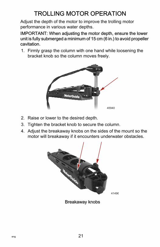
Adjust the depth of the motor to improve the trolling motorperformance in various water depths.IMPORTANT: When adjusting the motor depth, ensure the lowerunit is fully submerged a minimum of 15 cm (6 in.) to avoid propellercavitation.1. Firmly grasp the column with one hand while loosening the
bracket knob so the column moves freely.
45940
2. Raise or lower to the desired depth.3. Tighten the bracket knob to secure the column.4. Adjust the breakaway knobs on the sides of the mount so the
motor will breakaway if it encounters underwater obstacles.
41496
Breakaway knobs

TROLLING MOTOR OPERATION
22 eng
Foot Pedal Operation
! WARNINGRotating propellers can cause serious injury or death. Never startor operate the motor out of water.
DIRECTION CONTROLPivot the foot pedal heel‑down to steer left and toe‑down to steerright. To operate the motor in reverse, continue to press all the waydown on the foot pedal in either operation. The 400° steering rangeallows the operator to point the motor past 360° from both the leftand right side.The directional indicator on the top of the motor corresponds to theposition of the lower unit.
a - Heel‑down position – left turnb - Center detent position – straightc - Toe‑down position – right turn
SPEED CONTROLUse the three‑position toggle switch to operate the motor at anygiven speed.1. Constant on ‑ motor runs continuously on the selected speed
without the use of the momentary button.2. Momentary ‑ motor runs continuously on the selected speed
with the momentary button depressed.
a b c
46040

TROLLING MOTOR OPERATION
eng 23
3. High‑bypass ‑ motor runs continuously on full speed(bypassing the speed setting) with the momentary buttondepressed.
Control the speed of the motor by adjusting the speed control knobon the foot pedal. Use the momentary switch when operating thetrolling motor in momentary or high‑bypass operation.
a - On‑off toggle switchb - Speed control knobc - Three‑position toggle
switchd - Momentary button
Use the on‑off toggle switch to power the motor on and off.
a - On‑off toggle switchb - Off positionc - On position
a
b
c
d
41386
41385
ab
c

MAINTENANCE AND STORAGE
24 eng
Trolling Motor CareTo keep your trolling motor in the best operating condition andretain its dependability, your trolling motor must receive periodicinspections and maintenance. Keep it maintained properly toensure the safety of you and your passengers.
! WARNINGNeglecting to inspect, maintain, or repair your trolling motor canresult in product damage or serious injury or death. Do notperform maintenance or service on your trolling motor if you arenot familiar with the correct service and safety procedures.
Record all maintenance performed and save maintenance workorders and receipts.
SELECTING REPLACEMENT PARTSUse only original MotorGuide replacement parts.
Inspection and Maintenance ScheduleBEFORE EACH USE• Inspect for loose or corroded wiring connections.• Check the tightness of the battery lead connections.• Check the tightness of the propeller nut.• Check the propeller blades for damage.
AFTER EACH USE• Disconnect the battery cables from the power source or
unplug the motor from the boat.• After each use, check each side of the propeller and propeller
shaft for debris such as weeds and fishing line. Remove alldebris.
• Check the tightness of the propeller nut.• Rinse the trolling motor with clean water to remove dirt and
dust that may scratch the surface.

MAINTENANCE AND STORAGE
eng 25
EVERY 100 HOURS OF USE OR ANNUALLY• Periodically lubricate all the pivot points with a nonaerosol,
nonsolvent based lubricant.IMPORTANT: Never use an aerosol lubricant to grease or oil anypart of the unit. Many aerosol lubricants contain harmfulpropellants that can cause damage to various parts of the trollingmotor.
Pivot pointsa - Rear deck channel groovesb - Lockslide pinc - Door knob shaftd - Forward deck channel grooves
TubeRef No. Description Where Used Part No.
95 2-4-C withTeflon Pivot points 92-802859A 1
• Check the tightness of bolts, nuts, and other fasteners.• Inspect the battery. Refer to Battery Inspection.
Storage PreparationThe major consideration in preparing your trolling motor for storageis to protect it from corrosion and damage caused by freezing oftrapped water.
c
da
41572
b
MAINTENANCE AND STORAGE
26 eng
Refer to the Maintenance—Inspection and MaintenanceSchedule section and complete the appropriate care instructionsto prepare your trolling motor for storage. Store the trolling motorin a dry location where it will not be affected by temperatures below‑29 °C (‑20 °F).IMPORTANT: Trolling motors stored in temperatures below 0 °C(32 °F) should be operated slowly for a minimum of 15 minutesbefore going above 30% operation.
Battery InspectionThe battery should be inspected at periodic intervals to ensureproper trolling motor operation.IMPORTANT: Read the safety and maintenance instructionswhich accompany your battery.1. Ensure that the battery is secured to the vessel.2. Ensure that the battery cable terminals are clean, tight, and
correctly installed. For installation instructions, refer toBattery Connection.
3. Ensure that the battery is equipped with a battery box toprevent accidental shorting of the battery terminals.
Propeller Replacement
! WARNINGPerforming service or maintenance without first disconnectingthe battery can cause product damage, personal injury, or deathdue to fire, explosion, electrical shock, or unexpected motorstarting. Always disconnect the battery cables from the batterybefore maintaining, servicing, installing, or removing motorcomponents.
REMOVING THE PROPELLER1. Disconnect the battery cables from the power source.2. While holding the propeller blade with one hand, use a
propeller wrench or pliers to remove the propeller nut.

MAINTENANCE AND STORAGE
eng 27
IMPORTANT: If the propeller cannot be removed easily, hold oneblade and use a rubber mallet to lightly tap the backside of theopposite blade. If the propeller cannot be removed, refer toTroubleshooting.NOTE: If the propeller pin is bent, replace the propeller pin.
a - Propeller pinb - Propellerc - Propeller nutd - Propeller wrench
Recommended MotorGuide AccessoryDescription Part Number
MotorGuide Prop Wrench Kit MGA050B6
INSTALLING THE PROPELLER1. Rotate the motor shaft to insert the propeller pin horizontally.2. Install the propeller onto the motor shaft by engaging the
propeller onto the propeller pin.3. Install the propeller nut. Tighten securely.4. Use a MotorGuide propeller wrench or pliers to tighten the
propeller nut another ¼ turn.
Foot Pedal Cable Tension AdjustmentThe foot pedal cable tension adjustment is correct when theexposed number of threads on the tension adjustment shafts areapproximately the same and the amount of deflection of the longexposed foot pedal cable under a 9.1 kilogram force (20 lbf) pull isapproximately 19 mm (3/4 in.).
a
bc
d
45945

MAINTENANCE AND STORAGE
28 eng
To check for proper foot pedal cable tension, apply a9.1 kilogram force (20 lbf) pull at the center of the long exposedfoot pedal cable. The amount of deflection of the cable should beapproximately 19 mm (3/4 in.). If the deflection is not correct, usea 13 mm (1/2 in.) wrench to adjust the cable tension nuts to obtainthe proper deflection.IMPORTANT: Equal adjustments should be made to each cabletension nut to maintain an equal right and left steering radius withthe foot pedal.
a - Long cable tension pull pointb - Exposed threads of tension adjustment shaftsc - Cable tension adjustment nuts
Description kilogramforce lbf
Long exposed foot pedal cable tension 9.1 20
abb
c c
43523

OWNER SERVICE ASSISTANCE
eng 29
TroubleshootingNOTE: For service information, contact any certified MotorGuideservice center. For a full listing of MotorGuide service centers, goto www.motorguide.com or contact any Mercury Marine Serviceoffice.
Symptom Possible Cause Resolution
Loss of power
Weak 12 volt trollingmotor battery
Check 12 volt batterycharge. Recharge orreplace battery asrequired.
Loose or corrodedbattery connections
Inspect batteryconnections forcleanliness andtightness.
Propeller is loose,damaged, or off‑balance
Refer to PropellerReplacement.
Wiring or electricalconnection faulty
Wire gauge from thebattery to the trollingmotor is insufficient. 6gauge wire isrecommended.
Magnets cracked orchipped
The motor will whine orgrind. Contact servicecenter.
Water intrusion in thelower unit Contact service center.

OWNER SERVICE ASSISTANCE
30 eng
Symptom Possible Cause Resolution
Excessive noise,vibration
Motor shaft is bent Contact service center.
Propeller is loose,damaged, or off‑balance
Refer to PropellerReplacement.
Damaged bearings orbushings Contact service center.
Magnets interfering witharmature
Turn off the power andmanually rotate thepropeller. If the propellerdoes not rotate freely witha slight magnetic drag,contact service center.
Magnets cracked orchipped
The motor will whine orgrind. Contact servicecenter.
Motor failure(motor runs at partialspeed)
Electrical
Connections in the tophousing may be loose ordamaged. Contactservice center.
Thermal protectionTemperature exceedsspecification. Contactservice center.
Damaged speedpotentiometer Contact service center.
Propeller is loose,damaged, or off‑balance
Refer to PropellerReplacement.

OWNER SERVICE ASSISTANCE
eng 31
Symptom Possible Cause Resolution
Motor failure(motor does not run)
Weak 12 volt trollingmotor battery
Check 12 volt batterycharge. Recharge orreplace battery asrequired.
Loose or corrodedbattery connections
Inspect batteryconnections forcleanliness andtightness.
Wiring or electricalconnection faulty
Wire gauge from thebattery to the trollingmotor is insufficient. 6gauge wire isrecommended.
Electrical
Check the connector for aloose or damagedconnection. Contactservice center.
Thermal protectionTemperature exceedsspecification. Contactservice center.
Three‑position switch isdamaged Contact service center.
Fuse on circuit breaker isopen
Replace the fuse or resetthe circuit breaker onlyafter determining the rootcause of the problem.
Magnets interfering witharmature
Turn off the power andmanually rotate thepropeller. If the propellerdoes not rotate freely witha slight magnetic drag,contact service center.
Boat wiring Contact service center.The motor does notoperate in the samedirection as thedirectional indicator
Directional indicatormisaligned Contact service center.

OWNER SERVICE ASSISTANCE
32 eng
Symptom Possible Cause Resolution
Inaccurate temperaturereading
Lower unit not fullysubmerged
Adjust the depth of themotor. Ensure the lowerunit is fully submerged.Refer to Adjusting theMotor Depth.
Damaged nose cone Contact service center.Damaged sonar cable Contact service center.
Mount is hard to unlatchwith the pull rope
Mount bracket is not levelor twisted
Loosen or twist the twoforward bracket screwsslightly and latch thebracket. Continue toloosen each of thebracket screws until thebracket releases easily. Ifnecessary, install shimwashers (not supplied)and then tighten thescrews. Refer to ProductInstallation for help.
Difficulty removingpropeller
Bent propeller pin
Hold one blade and lightlytap the opposite bladewith a rubber mallet.Use a putty knife on bothsides of the propeller toapply equal pressure.
Bent armature shaft Contact service center.
Service AssistanceYour satisfaction with your product is very important to us. If youhave a problem or question about your motor, contact your dealeror any certified MotorGuide Service Center. For more serviceassistance information, refer to Warranty Information.The following information will be needed by the service office:• Your name and address• Daytime telephone number• Model and serial number of your trolling motor• Proof of purchase or registration verification• Nature of problem

OWNER SERVICE ASSISTANCE
eng 33
Mercury Marine Service OfficesFor assistance, call, fax, or write. Please include your daytimetelephone number with mail and fax correspondence.
United States, Canada
Telephone English ‑ (920) 929‑5040Français ‑ (905) 636‑4751
Mercury MarineW6250 W. Pioneer RoadP.O. Box 1939Fond du Lac, WI 54936-1939Fax English ‑ (920) 929‑5893
Français ‑ (905) 636‑1704Website www.motorguide.com
Australia, PacificTelephone (61) (3) 9791‑5822 Brunswick Asia Pacific Group
132-140 Frankston RoadDandenong, Victoria 3164Australia
Fax (61) (3) 9706‑7228
Europe, Middle East, AfricaTelephone (32) (87) 32 • 32 • 11 Brunswick Marine Europe
Parc Industriel de Petit-RechainB-4800 Verviers,Belgium
Fax (32) (87) 31 • 19 • 65
Mexico, Central America, South America, CaribbeanTelephone (954) 744‑3500 Mercury Marine
11650 Interchange Circle NorthMiramar, FL 33025U.S.A.
Fax (954) 744‑3535
Brunswick Asia Pacific GroupTelephone (65) 65466160 T/A Mercury Marine Singapore Pte Ltd
29 Loyang DriveSingapore, 508944Fax (65) 65467789