Texas Hydrogen Highway Fuel Cell Hybrid Bus and Fueling ...
94
1 Texas Hydrogen Highway Fuel Cell Hybrid Bus and Fueling Infrastructure Technology Showcase Final Scientific/Technical Report Houston Advanced Research Center DE-FG36-08GO88117 September 1, 2008 to February 28, 2011 Submitted to U.S. Department of Energy Revised June 30, 2012 (original submittal May 31, 2011)
Transcript of Texas Hydrogen Highway Fuel Cell Hybrid Bus and Fueling ...

1
Texas Hydrogen Highway Fuel Cell Hybrid Bus and Fueling Infrastructure Technology Showcase
Final Scientific/Technical Report
Houston Advanced Research Center DE-FG36-08GO88117
September 1, 2008 to February 28, 2011
Submitted to U.S. Department of Energy Revised June 30, 2012 (original submittal May 31, 2011)

2
Project Information DOE Award No: DE-FG36-08GO88117 Name of Recipient: Texas H2 Coalition
Name of Project: Texas Hydrogen Highway: Fuel Cell Hybrid Bus and Fueling Infrastructure Technology Showcase
Project Director: David Hitchcock, Texas H2 Coalition Managing Director Team Members: University of Texas at Austin Center for Electromechanics, Gas
Technology Institute, and Houston Advanced Research Center Project Period: August 1, 2008 to February 28, 2011
Executive Summary The Texas Hydrogen Highway project has showcased a hydrogen fuel cell transit bus and hydrogen fueling infrastructure that was designed and built through previous support from various public and private sector entities. The aim of this project has been to increase awareness among transit agencies and other public entities on these transportation technologies, and to place such technologies into commercial applications, such as a public transit agency. The initial project concept developed in 2004 was to show that a skid-mounted, fully-integrated, factory-built and tested hydrogen fueling station could be used to simplify the design, and lower the cost of fueling infrastructure for fuel cell vehicles. The approach was to design, engineer, build, and test the integrated fueling station at the “factory”; then install it at a site that offered educational and technical resources; and provide an opportunity to showcase both the fueling station and advanced hydrogen vehicles. The two primary technology components include:
• Hydrogen Fueling Station: The hydrogen fueling infrastructure was designed and built by Gas Technology Institute primarily through a funding grant from the Texas Commission on Environmental Quality. It includes hydrogen production, clean-up, compression, storage, and dispensing. The station consists of a steam methane reformer, gas clean-up system, gas compressor and 48 kilograms of hydrogen storage capacity for dispensing at 5000 psig. The station is skid-mounted for easy installation and can be relocated if needed. It includes a dispenser that is designed to provide temperature-compensated fills using a control algorithm. The total station daily capacity is approximately 50 kilograms.
• Fuel Cell Bus: The 22’ transit passenger bus built by Ebus, a company located in Downey, CA, was commissioned and acquired by GTI prior to this project. It is a fuel cell plug-in hybrid electric vehicle which is ADA compliant, has air conditioning sufficient for Texas operations, and regenerative braking for battery charging. It uses a 19.3 kW Ballard PEM fuel cell, will store 12.6 kg of hydrogen at 350 Bar, and includes a 60 kWh battery storage system.
During the five years preceding this project (2004 to 2008), support and coordination was achieved through several public and private sector sponsors resulting in site selection and

3
development for a fuel cell bus and fueling station in Austin, Texas. Project participants in this current DOE funded project have used the extensive hydrogen technology assets that were made available by these other sponsors to inform Texas target audiences on hydrogen and fuel cell applications. These Austin-based assets (bus and fueling station) have illustrated the potential for commercialization of hydrogen-powered transit buses, fueling infrastructure and related technologies. The project has also showcased the modeling techniques developed through prior efforts that can be used to design hydrogen vehicle and fueling solutions in other locations and for other applications. The station and bus are housed at the J.J. Pickle Research Center, University of Texas at Austin located in north Austin. The hydrogen fueling station is maintained by both GTI and UT personnel. The project showcased the fueling station and a plug-in hybrid electric fuel cell transit bus both of which can operate in real-world commercial applications. It serves to validate the potential for transit agencies (and others) to operate similar vehicles, thereby reducing emissions and the nation’s dependency on foreign sources of energy for transportation fuels. During 2011 after conclusion of this project, the initiative will be continued under separate funding through support from the State of Texas and the U.S. Department of Transportation Federal Transit Administration. A new larger transit bus (Proterra) is being placed in Austin for transit service at Capital Metro Transit. The Texas Hydrogen Highway project has increased the understanding of transit management and operation staff on utilizing a fuel cell bus and fueling infrastructure, making the transition to a new vehicle and improved station possible.
Accomplishments: Goals and Objectives The objectives of the project included the following:
• To advance commercialization of hydrogen-powered transit buses and supporting infrastructure
• To provide public outreach and education by showcasing the operation of a 22-foot fuel cell hybrid shuttle bus and Texas’s first hydrogen fueling infrastructure
Hydrogen fueling station. University of Texas Pickle Research Center, Austin, TX. Reformer, processing, storage, etc., etc.. Can produce 60 kg per day. 2009.
Hydrogen fuel cell plug-‐in hybrid electric transit bus. Manufactured by Ebus. Located at the University of Texas Pickle Research Center in Austin, Texas. 2008.

4
• To showcase operation of zero-emissions vehicle for potential transit applications As mentioned above, the project successfully demonstrated an early vehicle technology, the Ebus plug-in hybrid fuel cell bus, and that success has led to the acquisition of a more advanced vehicle that can take advantage of the same fueling infrastructure. Needed hydrogen station improvements have been identified that will enhance the capabilities of the fueling infrastructure to serve the new bus and to meet the transit agency’s needs. Needed improvements that were identified include:
• The capacity of the station needs to be increased for the Proterra bus to be deployed following this project (in 2012). The station’s daily capacity was 60 kg/day, however only 15 kg could be dispensed at one time due to the size of on-site high pressure storage. Additional storage was needed to provide a full fill at one time without the bus needing to return additional re-fueling during the day.
• A leaking roof needed repair so that rainwater could not seep into the station, possibly damaging electronics.
• Communications needed improvement so that station operating parameters could be reviewed and the station could be fully operated by remote access.
Over the course of this project, public officials, local government staff, and transit operators were engaged in outreach and education activities that acquainted them with the real world operation of a fuel cell bus and fueling infrastructure. Transit staff members in the Dallas/Ft. Worth region were invited to a workshop in Arlington, Texas at the North Central Texas Council of Governments to participate in a workshop on hydrogen and fuel cells, and to see the fuel cell bus in operation. The bus was trucked to the meeting for this purpose so that participants could see and ride the bus. Austin area transit staff members visited the fueling site in Austin to be briefed on the bus and to participate in a fueling demonstration. This led to further meetings to determine how a fuel cell bus and fueling station could be deployed at Capital Metro Transit. Outcomes of these meetings included agreement to pursue a new fuel cell bus that was being demonstrated in South Carolina at that time. Through such efforts, transit staff (as well as other governmental staff) in the major Texas metropolitan areas are now more aware of fuel cell bus technology and fueling infrastructure. Target urban regions that expressed additional interest during the project in response to the outreach meetings and showcase events include San Antonio and Austin, Texas. The bus and fueling infrastructure were showcased at many events during the course of the project. This showcasing included events at the project site as well as demonstration visits in the Dallas/Ft. Worth area and Austin where participants were given the opportunity to examine the bus and go on demonstration rides. The bus and fueling infrastructure were also reviewed in detail at five hydrogen workshops and several conferences and workshops in the target Texas regions. In summary, the project objectives were achieved in the following ways:
• Through presentations and papers provided to a variety of audiences in multiple venues, the project team fulfilled its goal of providing education and outreach on hydrogen

5
technology to statewide audiences. The project team generated interest that exists well beyond the completion of the project, and indeed, helped to generate financial support for a subsequent hydrogen vehicle project in Austin.
• The University of Texas, Center for ElectroMechanics operated the fuel cell-electric Ebus vehicle for over 13,000 miles in Austin, Texas in a variety of routes and loading configurations.
• The project took advantage of prior efforts that created a hydrogen fueling station and fuel cell electric-hybrid bus and continued to verify their technical foundation, while informing and educating potential future users of how these technologies work.
Keywords: hydrogen, fuel cell, hybrid electric, plug-in, transit bus, shuttle bus, technology showcase, outreach, education, fueling, reformer Summary of Project Activities and Challenges The hydrogen fuel station was commissioned in February 2010 after considerable attention to performance and safety measures. Once commissioned, the station began hydrogen generation. During the project performance period, a number of maintenance issues arose, consistent with mechanical challenges associated with a prototype showcase project (detailed below). As a result, some of the showcase opportunities were supported with hydrogen supplied via tube trailer. The station and bus have been available during the project period for showcase events for limited, invited visitors, which included bus rides and station tours (see Appendix A). The intent was to work closely with organizations and individuals who could be involved in use and development of the vehicle and associated technologies, particularly the Texas transit community. In addition to these showcase events, there have been outreach events in which this project was thoroughly described and discussed with participants (see Appendix A). This included events in Austin (3), San Antonio (2), Houston, and the Dallas/Ft. Worth areas held in coordination with the Texas Hydrogen Education project. The events included briefing of Texas legislative staff, training for transit staff, and targeted interchanges with Capital Metro Transit staff. Part of the outreach and education was modeling of the vehicle’s use for transit operations. It is essential to transit agencies that there are methods for determining if the vehicle is suited to particular routes and their operation. Toward that end, PSAT modeling (Powertrain System Analysis Toolkit) was completed prior to this project to analyze applications on specific transit routes (see Appendix B). During this project, UT-CEM collaborated with Georgia Tech (Center for Innovative Fuel Cell and Battery Technologies, Georgia Tech Research Institute) on advanced energy storage and modeling techniques of electrified vehicles, including previous PSAT model development of the Ebus and studies of ultracapacitor assisted batteries. As mentioned above, a number of fueling station maintenance issues arose, consistent with mechanical challenges of a prototype showcase project. While these items were all addressed, the timing for repairs and maintenance minimized the amount of time available for some

6
showcase events. Consequently, vehicle operations were supported by delivered hydrogen provided by Airgas via a tube trailer. The following are station challenges faced and addressed during the project period:
• GTI determined that the station needed a larger air compressor to provide adequate cooling to the electronics, using venturi chiller within the station, during the extreme heat of the Texas summer months. Retrofit with a larger air compressor was completed the project period.
• During start-up, the hydrogen production levels did not keep up with the hydrogen compressor. The size of the pre-compression hydrogen buffer tank to prevent excessive compressor cycling.
• The shift and reformer units in the hydrogen station were pressure tested with nitrogen gas to determine location and cause of pressure drop seen during prior operation. GTI found blockages in both the shift and reformer units. Each unit was removed from the station and shipped back to GTI for maintenance and repair. The source of the flow blockage in the reformer system was identified and corrected.
• A buffer tank was installed from the incoming natural gas to the station, prior to the compressor. By installing this tank, GTI mitigated the pressure relief chattering that was occurring with the natural gas regulator at the UT supply line. In addition, GTI installed a large natural gas tank on the outlet side of the compressor. By doing so, GTI was able to decrease the number of start-stop cycles of the natural gas compressor.
• The station’s exhaust fan was rubbing due to worn bearings. A new fan was installed and tested.
• Secure communications were established so that the system could be monitored and operated remotely.
• A small crack in a non-pressurized joint weld was observed on the reformer. After analysis, GTI determined that the repair could be made “in-situ” and the repair was completed shortly afterward.
• Station landscaping was completed in November 2009. • During commissioning activities in November 2009, about 1500 psig was manufactured
by the station reformer and injected into the high back storage vessel on the station skid. Gas quality was measured during the hydrogen generation process. CO levels were detected that were higher than allowable per SAE J2719 specifications. This was determined to be caused by the PSA unit. GTI contacted the PSA manufacturer, QuestAir, and the PSA was recalibrated to correct the excessive CO levels.
The original award from DOE was issued as of July 29, 2008, with a project start date of September 1, 2008, but the award was restricted while DOE and the Texas H2 Coalition negotiated the final terms and conditions and budget plan. Because of the restricted award status, Coalition project participants were not allowed to request reimbursement for work performed during this period. On May 29, 2009, DOE issued award modification #1 to remove the restricted status, allowing the project team members to start fully implementing the project work plan in July 2009. An unrestricted award notice giving the Coalition authorization to begin grant activities was received in June 2009.

7
Summary of Project Tasks Task 1.1: Complete the preparation of fuel cell bus
Summary: The bus was acquired prior to the beginning of this project. Bus preparation was mainly addressed earlier in the program to address issues with fuel cell reliability, which had been previously identified under a prior program. Challenges/Problems: The problem involves hydration of the fuel cell stack which is controlled by opening and closing of valves in the balance of plant’s water trap system. Too much or too little hydration in the stack affected power output from the fuel cell system. In some cases the system would shut down, requiring a lengthy re-start time. Solutions: Operation of the water trap valves is controlled by the manufacturer’s control software. As was done before on the previous program, we worked with the manufacturer to install updated software that changed the frequency and duration of valve operation. This improved fuel cell power output and reliability.
Tasks 1.2: Collect, model, and simulate routes (reviews and presentations) Summary: PSAT (Powertrain Simulation Analysis Toolkit) developed by Argonne National Laboratories, is a forward-looking simulation tool that enables the construction and analysis of detailed vehicle models and control systems by integrating the capabilities of Matlab, Simulink, Stateflow, and a graphical user interface. As part of previous work, UT-CEM staff analyzed various routes in Austin and the surrounding area for use of the fuel cell bus under this program, as well as routes at other transit agencies outside Austin to better understand the capability of bus operation, (e.g., Fort Bend County Transit Agency). This work was re-examined during this project in considering discussions with Capital Metro during this project. See Appendix B for examples of PSAT presentation materials used in this project). Challenges/Problems: No specific additional problems were encountered in using results from the previous work, which established a correlated PSAT model of the Ebus based upon bus data from pre-determined routes. The previous work showed that Ebus performance (range, useable energy) could be predicted within 5%. Having this tool and the previous analysis provided supportive information that was used with outreach and showcase participants. Solutions: n/a
Task 1.3: Conduct bus staff training Summary: UT Center for Electromechanics staff met with Austin transit staff to review the potential use of the fuel cell bus and fueling station in normal transit operations. In addition, transit staff participated in showcase events in other Texas cities where they had the opportunity to see the bus in operation. The bus staff training for Capital Metro was successful in creating the opportunity for a follow-up project with a new transit placed in operation by the transit agency. This new program is sponsored by USDOT FTA and the Texas Commission on Environmental Quality, and involves a twelve-month demonstration of Proterra’s hydrogen fuel cell plug-in hybrid transit bus. Challenges/Problems: No problems encountered. Solutions: n/a
Task 2.1: Support, prepare, and start-up station

8
Summary: The hydrogen station was installed at the University of Texas, Center for ElectroMechnics in Austin, Texas. While not accessible to the general public (the University research campus has a fenced security perimeter), the station configuration was similar to one that would be used in a consumer environment. The station was delivered via a tractor-trailer rig on a single skid, with a separate skid for the dispenser. The hydrogen station consists of an integrated natural gas clean-up system and compressor, steam methane reformer, reformate clean-up PSA, hydrogen compressor, and high pressure hydrogen storage (48 kilograms). A separate dispenser is also included in the station configuration that provides hydrogen for vehicles at a pressure of 5000 psig. The station is equipped with a controller with automated operation and remote monitoring capabilities. There is also real-time hydrogen gas quality monitoring, ventilation and various flame monitors, gas sensors, and automatic shut-off devices for system safety. Each of these sub-systems was tested and the entire integrated station was taken through start-up to produce hydrogen for the project. Challenges / Problems: During start-up, GTI monitored all subsystems and discovered some mechanical problems with the hydrogen generation process that had not been identified during lab operation and demonstration prior to the project. These mechanical problems did not present safety issues, but delayed hydrogen production while they were being diagnosed. No mechanical issues were present with the compressor and dispenser which were utilized for fueling the fuel cell bus during the performance period of the project. Solutions: Since mechanical repairs and system modifications were not part of the project scope, the project participants utilized delivered hydrogen for operation of the bus and for showcasing activities. The station did generate some hydrogen for use in the project and the storage, compressor, and dispenser were used throughout the project since they were not impaired by any mechanical issues. Separate funding sources were identified to achieve the needed station updates and modification, and that work is proceeding in a separate, subsequent project. The station is expected to be fully operational in this subsequent project.
Task 2.2: Conduct station training and follow-up Summary: Two levels of training occurred during the project. A thorough training effort was conducted for the benefit of University of Texas personnel who would be immediately responsible for operating the station during the project. GTI and UT-CEM personnel worked extensively on-site for cross training on the station operation, controls, and basic maintenance. This training also extended to safety officials at the University of Texas. A comprehensive safety plan was drafted and reviewed by all parties (Safety Plan, Appendix C). A second, lower level of training occurred for the general public. As part of outreach and education activities, short training events were held on site at the station to show the general public what is involved in fueling a hydrogen vehicle. Additional outreach events to the general public showed pictorially at off-site locations on how the station operated and how consumers would fuel a hydrogen vehicle. Challenges/ Problems: None identified. Solutions: Not applicable.
Tasks 3.1: Bus operation
Summary: Bus operation has continued throughout the project. Under this program and prior to each showcase event, staff completed vehicle checks to ensure that the bus was
9
operational. This included 1) running the fuel cell system to ensure proper operation (i.e., hydration of the fuel cell stack), 2) regular battery maintenance including watering and deep-discharge cycling, 3) bus fueling with hydrogen and battery recharging, 4) bus cleaning, and 4) overall maintenance checklist typical for transit buses. Challenges/Problems: The main challenge to showcasing the bus in locations outside of Austin, TX was the availability of hydrogen fuel and re-charging facilities. Without the needed fueling infrastructure, the bus range is limited to the hydrogen onboard and the onboard battery’s single charge. Solutions: To address this range limitation, the bus was either operated locally, or shipped via a flatbed trailer to the showcasing event.
Task 3.2: Mid-term inspection and evaluation. Summary: During April 2010, UT-CEM completed the mid-term inspection and evaluation of the shuttle bus. This included a detailed check-out of the bus energy systems (batteries and fuel cell), electrical and mechanical systems, and data acquisition system. Challenges/Problems: UT-CEM identified two issues during the mid-term inspection/evaluation of the shuttle bus. (1) The first item that needed maintenance/replacement was the bus’s auxiliary 12VDC battery which powers the onboard vehicle controller and auxiliary systems. This is a standard automotive battery, which has a finite life and requires periodic recharging or replacement. (2) The second item was the identification of a ground fault within the circuitry for the Fast Charger option on the shuttle bus. A wire harness tied into a safety switch on the vehicle's charger receptacle door was showing a short to ground (chassis) and preventing the bus from being charged appropriately. Solutions: (1) UT-CEM was able to easily solve the auxiliary battery issue by periodically recharging the 12VDC automotive battery with an overnight charger for a short time; however, eventually the battery needed complete replacement. (2) To solve the ground fault within the Fast Charger circuitry and allow the bus to be recharged, UT-CEM disconnected the Fast Charger inputs to the vehicle controller and disabled this feature. UT-CEM was able to do this since the facilities at UT-CEM do not use a Fast Charger. The bus is recharged via a Slow Charger overnight. Disabling the Fast Charger option has no affect on the Slow Charge process and UT-CEM was able to continue using the bus normally.
Tasks 3.3: Conduct education and outreach activities The primary aim of the project was showcasing the vehicle and fuel station for education and outreach, which included highlighting vehicle and station operations in ways that could be applicable in transit and other similar operations. The various showcase activities are outlined below under “Presentations: Workshops and Meetings” and listed again in Appendix A. Sample presentations from outreach events are contained in Appendix D.
Project Products Papers
• Clay Hearn, Richard Thompson, “PSAT Modeling and Evaluation of Plug-In Hybrid Fuel Cell Shuttle Bus”, September 2009, IEEE Vehicle Power and Propulsion Conference 2009, Dearborn, Michigan.

10
• In collaboration with Georgia Tech, paper submitted to the Journal of Power Sources on advanced battery modeling for electric and hybrid electric vehicles.
• Austin Hydrogen Station Safety Plan, Texas H2 Coalition, prepared by Gas Technology Institute, September 2009.
• “Fueling the Emerging Hydrogen Economy”, presentation to the American Society of Chemical Engineers, J.B. Weeks, March 2010.
Presentations: Workshops and Meetings
• Poster sessions at National Hydrogen Association annual conference in Columbia, SC in February, 2009:
o Low-Emission Vehicle Technologies For Public Transportation, UT–Center for Electromechanics (R. Thompson, M. Lewis, C. Hearn), Gas Technology Institute (Brian Weeks)
o PSAT Vehicle Technology and Modeling, UT–Center for Electromechanics (R. Thompson, M. Lewis, C. Hearn), and Gas Technology Institute (Brian Weeks)
o State-of-the-Art Hydrogen Infrastructure for Texas, UT–Center for Electromechanics (R. Thompson, M. Lewis, C. Hearn), Gas Technology Institute (Brian Weeks)
o Texas Hydrogen Highway, Texas H2 Coalition (D. Hitchcock) • Briefing for Texas legislative staff. Presentations on fueling station and fuel cell bus; bus
was showcased for attendees. April 2009. • Showcase event at the Pickle Research Center for conference attendees from the UT-
Ferguson Structural Engineering Lab, Texas Department of Transportation, and the Federal Highway Administration. September 16, 2009.
• Presentations at Texas Hydrogen Education workshops: “There is a Hydrogen Fuel Cell Bus Operating in Texas” (R. Thompson, UT-CEM) and “Hydrogen Infrastructure 101”, (B. Weeks, GTI) as part of Texas Hydrogen Education workshops in San Antonio (2), Houston, Dallas/Ft. Worth and Austin (2).
• Presentation and poster session, Austin Climate Protection Conference & Expo, January 2010. Fuel cell bus showcased for conference participants.
• Fuel Cell Bus and Fuel Station Operation and Maintenance. Presentations and coordination meetings with officials from Capital Metro and UT-CEM. Meetings held at both Capital Metro offices and UT-CEM. March 2010.
• Hosted tour of fuel cell bus and fueling station for attendees of annual transportation conference of state transportation officials, 2010 Southeastern States Equipment Managers Conference, June 2010.
Networks/Collaborations
• Capital Metro Transit, Austin, Texas • Center for Innovative Fuel Cell and Battery Technologies, Georgia Tech Research
Institute, Georgia Institute of Technology • Texas Clean Cities Programs (San Antonio, Austin, Houston, and Dallas/Ft. Worth) • City of Austin, Austin Energy • 2010 Fuel Cell Seminar

11
Station Installation Photos
Hydrogen station being delivered to
the University of Texas Pickle Research Center, November 2008
Hydrogen station being lifted by crane from delivery truck
at the University of Texas Pickle Research Center, November 2008
12
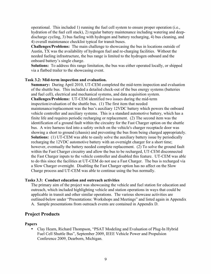
Hydrogen station being lowered onto concrete pad
at the University of Texas Pickle Research Center, November 2008
Station and dispenser cabinet installed on-site at
the University of Texas J.J. Pickle Research Center in Austin, Texas (landscaping incomplete as of this photo)

13
The Hydrogen Fuel Cell Shuttle Bus loaded for transport
to the Dallas/Ft. Worth area for hydrogen workshop, December 2009

14
Appendices Appendix A: Texas Hydrogen Highway Showcase and Outreach Events .......................... 15 Appendix B: Slides from PSAT Modeling Presentation ...................................................... 16 Appendix C: Texas H2 Coalition Project Safety Plan .......................................................... 18 Appendix D: Examples of Showcase and Outreach Presentations ....................................... 51 Hydrogen Fuel Cell Bus, R. Thompson, CEM/UT ...................................................... 52 Fueling Infrastructure, B. Weeks, GTI ........................................................................ 65

15
Appendix A Texas Hydrogen Highway Showcase and Outreach Events
Showcase Events
• Showcase and briefing for Texas legislative staff. Presentations on fueling station and fuel cell bus; bus was available at this briefing for attendees. Texas State Capital Area. April 2009.
• Showcase event for conference attendees from the UT-Ferguson Structural Engineering Lab, Texas Department of Transportation, and the Federal Highway Administration. Pickle Research Center. September 16, 2009.
• Showcase event at the North Central Texas Council of Governments for transportation, fleet, and government staff. Bus transported to the Dallas-Ft. Worth area for showcase event. Arlington, Texas. December 3, 2009.
• Showcase event at the Austin Climate Protection Conference & Expo, Fuel cell bus provided for conference participants; also provided a poster session. Austin, Texas. January 2010.
• Showcase event on the fuel cell bus and fuel station operation and maintenance, including presentations and coordination meetings with officials from Capital Metro and UT-CEM. Meetings held at Capital Metro offices and UT-CEM. Austin, Texas. March 2010.
• Showcase event including tour of fuel cell bus and fueling station for attendees of annual transportation conference of state transportation officials, 2010 Southeastern States Equipment Managers Conference. Austin, Texas. June 2010.
• Showcase event, including a demonstration of bus fueling and bus rides as part of Hydrogen 101 Workshop. Event included transit staff, local government staff, and state officials. Austin, Texas at the Pickle Research Center. February 24, 2010.
• Showcase event providing demonstration rides during the 2010 Fuel Cell Seminar and Exposition with fuel cell vehicles from the University of Texas. San Antonio. Week of October 18, 2010.
Outreach Events
• Presentations at the San Antonio Hydrogen 101 Workshop. September 28, 2009 • Presentations at the Houston Hydrogen 101 Workshop. October 14, 2009. • Presentation to the Gulf Coast Chapter of the American Institute of Chemical Engineers
at the Annual Energy Symposium in Houston, Texas. March 4, 2010. • Support and participation for the Fuel Cell Seminar and Exposition in San Antonio,
Texas including display booth. Week of October 18, 2010. • Presentation on the station and bus at the Texas Hydrogen Briefing event following the
Fuel Cell Seminar. San Antonio, Texas. October 21, 2010.

16
Appendix B Slides from PSAT Modeling Presentations

Vehicle Modeling using PSAT (Powertrain System Analysis Toolkit)
• All electric vehicle – Deep cycle lead-acid
batteries – Advanced state of the art
batteries
• Fuel cell vehicle
• Fuel cell hybrid vehicle – Plug-in fuel cell – Fuel cell dominant hybrid

Modeling goal was to be able to predict vehicle performance for any given route
• Matched vehicle’s net energy consumption within 5%
• Approach helps others make better choices on emerging vehicle technologies
• Avoids the “build and test” approach
Main Campus Route PredictionCorrected Route and Aux Load vs. Measured data from 6/27/2008
Full Route InfoNet Battery
EnergyNet Traction
Motor EnergyAuxiliary Energy
FC Net Energy Out
H2 Consumed
FC Energy Conversion
Sum H2 and Battery Use
[kWh] [kWh] [kWh] [kWh] [kg] [kWh/kg] [kWh]6/27/2008 Main Campus Data 33.25 50.08 25.61 42.48 3.01 14.13 133.55PSAT Model 6004 35.91 52.38 25.62 42.1 2.9585 14.23 134.61Percent Difference 8.0% 4.6% 0.0% -0.9% -1.6% 0.7% 0.8%
Slope change with hydrogen consumption
due to fuel cell operation

18
Appendix C Project Safety Plan

TEXAS H2 COALITION
AUSTIN HYDROGEN STATION SYSTEM SAFETY PLAN
Revised: July 6, 2010

ii
Table of Contents 1 Safety Planning and Administration ..................................................................................................... 1
1.1 Policy statement for system safety plan ....................................................................................... 1
1.2 Goals for the system safety program ............................................................................................ 1
1.3 Organizational Experience ............................................................................................................ 2
1.4 Scope of the system safety program ............................................................................................ 3
1.5 System safety program management ........................................................................................... 5
1.6 Plan update procedures ................................................................................................................ 5
2 Hazard Analysis ..................................................................................................................................... 5
2.1 Fire Safety and Local Code Requirements .................................................................................... 7
2.2 System Siting ................................................................................................................................. 7
2.3 Hazard Analysis Table ................................................................................................................. 10
3 Operating Rules, Training, and Procedures ........................................................................................ 21
3.1 Training and Certification ............................................................................................................ 21
3.2 Maintenance Program Activities ................................................................................................. 21
4 Fueling Station Operation ................................................................................................................... 22
4.1 Monitoring of the Hydrogen Station ........................................................................................... 23
4.2 Visual Inspection ......................................................................................................................... 23
4.3 Vehicle Fueling ............................................................................................................................ 23
4.4 Resetting Station Operating Parameters .................................................................................... 25
4.5 Resetting Station ESD Button ...................................................................................................... 26
4.6 Engaging Station Reset Button after Automatic Station Shutdown ........................................... 26
5 System Safety Reviews, Reports, and Audits ...................................................................................... 27
6 Configuration Management ................................................................................................................ 27
7 Emergency Call‐out Procedures for Hydrogen ................................................................................... 28
8 EMERGENCY RESPONSE PROCEDURE ................................................................................................. 30

1
1 Safety Planning and Administration
This safety plan follows the outline and format of the U.S. Department of Transportation’s “System Safety Plan for Commercial Vehicles using Hydrogen as an Alternative Fuel”, released in November, 2007.
Safety has superseded all other operational concerns during the design, installation, and commissioning of this hydrogen fueling station. It is important to note that the fueling station covered by this document is NOT used by the public or commercial fleet operators, not accessible to the public or commercial feet operators, and has stringently controlled access and use for and by the University of Texas Center for ElelctoMechanics trained and knowledgeable personnel ONLY. This station has now been transferred to personnel located at the University of Texas, Center for Electromechanics who will be responsible for its continued safe, incident-free operation. Furthermore, one of the goals of the research and development program that resulted in the deployment of this station was to design and build a skid mounted self-contained fueling station that could be permitted by the local authority having jurisdiction. It was understood that perhaps unconventional methods of achieving appropriate and adequate safety levels and mitigation of hazards would be employed. Consequently, many sections within this safety plan will continue to be supplemented by local operators whose understanding and buy-in regarding safe operating procedures and protocols is critical to the overall success of the hydrogen fueling station and vehicle operations in Austin. The intentions of this approach are to demonstrate the reduced space and site modifications associated with a station design which can be shop fabricated and tested before delivery to the site, hence reducing installation time and improving reliability.
1.1 Policy statement for system safety plan The Texas H2 Coalition, its members, and project partners are committed to a clean, safe and healthy workplace and environment. All aspects of the Texas Hydrogen Highway project will be managed in a safe and environmentally responsible manner in accordance with the principles of this policy, and all applicable codes and safety regulations. We believe that adherence to this policy benefits our members, collaborators, and the public, both now and for the future, while improving the quality of the environment.
1.2 Goals for the system safety program Safety goals outlined by the DOT include:
• Safety considerations are incorporated into the design of facilities, operations, and maintenance practices for hydrogen systems and equipment.
• Hazards associated with hydrogen systems and equipment are identified, analyzed, and then eliminated or mitigated to achieve an acceptable level of safety.
• Identified hazards will be mitigated by the following system safety practices: o Design to eliminate or control the hazard o Add safety devices o Provide warning devices

2
o Institute special procedures and training
1.3 Organizational Experience The team involved in the station design, equipment layout, and input to this Safety Plan
include representation from the Gas Technology Institute (GTI)- the creator of the hydrogen production technology employed, GreenField Compression (GreenField)- the packager of the station equipment skid and manufacturer of the hydrogen dispenser and compressor, University of Texas, Center for ElectroMechanics (UT-CEM)- operators of the hydrogen fuel cell hybrid bus and station. Below is a brief description of the individuals who provided input. (More detailed biographies are available upon request.)
Gas Technology Institute
Tony Lindsay, P.E., has 26 years of experience in the energy industry, and 15 years dedicated to the development of fueling infrastructure for alternate transportation fuels. He earned a BSME in Thermo-Mechanical Engineering from the University of Illinois-Chicago, and currently serves as Principal Investigator for U.S. DOE Advanced Hydrogen Fueling Infrastructure Deployment project and U.S. DOE Small-scale LNG production project. Mr. Lindsay has designed and deployed over 40 compressed natural gas fueling stations, and has served as the Illinois industry member of the Alternative Fuels Advisory Board for 4 years.
Ken Kriha -- Principal Engineer, Mr. Kriha is responsible for overseeing GTI’s laboratory testing of hydrogen and advanced energy systems area. His areas of expertise include process control systems, data acquisition system management, and system modeling using advanced analytical tools. Mr. Kriha has extensive experience with high-pressure gas systems, fuel processors, fuel purification, and gas compression equipment and has run numerous programs for major clients, including major international vehicle manufacturers. He has a degree in Chemical Engineering.
Brian Weeks, P.E., BSCE., MBA, has 22 years experience in the energy, environmental, and economics fields as a project manager, regulatory manager, and technology program manager. Mr. Weeks managed U.S. and international projects for Texaco in distributed power generation, fuel cell stationary power, liquid fuels infrastructure, natural gas infrastructure, and hydrogen infrastructure; developed business plans and economic modeling for numerous natural gas and power generation projects; Member, SAE, ASCE, US Fuel Cell Council, and former Fuels Team Chair of California Fuel Cell Partnership. Mr. Weeks has written over a dozen reports and publications on technical, policy, and economic issues surrounding the adoption and deployment of advanced fuels technologies.
David Zuckerman. Mr. Zuckerman has an extensive automotive background with a focus
on alternative fuels. From technician to mechanical engineer, Mr. Zuckerman has been involved in the full spectrum. His range of experience has allowed him to focus on everything from individual parts (such as batteries, shocks and frames) to the integration of components comprising steering systems and rolling chassis. He has been part of design teams focused on specialty hydrogen and compressed natural gas vehicles as well as fueling station technologies to support alternative fuel vehicles.
University of Texas at Austin – Center or Electromechanics

3
Richard Thompson, P.E.,MSME, has 30 years experience in prototype development, 15 years experience in the development and testing of advanced transportation technologies. Mr. Thompson is currently Principal Investigator on research on hybrid electric vehicles, all-electric vehicles, and hydrogen-powered hybrids utilizing advanced technologies. These advanced technologies include both improved energy storage approaches (flywheel, chemical batteries, capacitors) and novel hybrid electric architectures (electric power control algorithms, motor/generators, power electronics, and hydrogen-powered energy sources) for improved vehicle performance. Under a recent USDOT/FTA program, Mr. Thompson and his team evaluated the first hydrogen fuel cell plug-in hybrid transit bus licensed to operation in the state and developed modeling techniques to predict the performance of hybrid vehicles for varied routes and under a range of operation conditions.
Michael Lewis.,MSME, has over 10 years experience in advanced research and
technology development at UT-CEM. Mr. Lewis’s early research responsibilities were focused on the development of a prototype advanced high-speed generator for an electromagnetic aircraft launching system. His current interests involve alternative fuelled vehicles, including hydrogen-powered vehicles, and alternative energy sources. Recent research duties include the demonstration of a plug-in hybrid fuel cell shuttle bus and the installation of the state’s first hydrogen gas refuelling station. Mr. Lewis is also currently studying portable hydrogen generation systems via chemical reactions with sodium compounds.
GreenField Compression, Inc.
Jared Hightower, is a graduate of Louisiana State University with a Bachelor in Mechanical Engineering, Jared has eleven years of experience in the compressed gas fueling industry. In his current position as Product Manager NGV/H2V, he is responsible for interfacing with engineering and production within GreenField, and working with engineers, contractors, and end users of compressed gas equipment. He is also involved with product costing and new product concept development.
David Pearce, has thirty-three years of sales, marketing and management experience
encompassing construction equipment, electric motors, motor controls, compressors and CNG Systems. He is a graduate of the University of Wisconsin system with degree in Business Administration and Management. Dave has management experience in developing and expanding markets for product lines resulting in sustained business growth. He has held positions as Key Accounts Manager for a major Mid-Western Caterpillar dealership, Manager NGV Systems for a major Mid-West Natural Gas Utility, and is the former Vice President of Sales for a leading independent NGV Equipment Packager. He has been involved in many facets of the NGV Industry since the early 1980’s, including past officer of the AGA-NGV Marketing Committee and ongoing member of the NGVC Market Development Committee, Chairman of Equipment Suppliers Council, Member of National Conference on Weights and Measures, and National Fire Protection Association.
1.4 Scope of the system safety program The identification of which equipment, procedures, activities, and locations are subject to the safety plan is important. For the Austin station, a combined safety plan for the fuel cell bus and the hydrogen fueling station will continue to be enhanced as the project progresses.

4
• Description of the hydrogen station configuration: The station is a fully integrated system with on-site hydrogen generation, purification, compression, and storage. It is housed in an equipment enclosure that fully complies with all codes and safety provisions for hydrogen generation, storage and dispensing facilities. A separate dispensing island is located approximately 20’ from the station equipment enclosure and will dispense fuel via an algorithm-controlled protocol designed specifically for hydrogen at 5000 psig.
• Description of the type and frequency of vehicles that will fuel there: The initial vehicle at the station will be a 22’ Ebus that is designed as a plug-in battery – fuel cell hybrid vehicle. The vehicle carries approximately 12 kg of hydrogen on-board storage.
• Description of the identity and backgrounds of the personnel who will be allowed to use the station: UT-CEM and GTI will provide trained personnel to operate the station. All station operators are required to receive training prior to performing ongoing operational duties or to fuel the bus.
• Description of the maintenance activities and who will perform them: Maintenance for compressor will be performed by GreenField. Maintenance for dispenser, hydrogen generation equipment, will be performed by a combination of UT-CEM and GTI personnel. Maintenance activities are listed in the station operating manual and will include:
o Maintenance for hydrogen generation equipment (includes reformer, natural gas compressor, desulfurization system, PSA, and enclosure skid ancillary equipment
o Maintenance for DM1 GreenField hydrogen compressor o Maintenance for G1E GreenField hydrogen dispenser
• Description of the safeguards that have been installed to prevent hydrogen accidents. At the Austin station this includes (but is not limited to):
o Signage along the front of the station o Facility fencing (the station is located in a fenced, secure campus
facility). o Security monitoring of the campus facility including the station location o Flame detectors adjoining the dispenser that monitors 120o field of
view including the high pressure storage area. o Gas detectors inside the compressor equipment enclosure and inside
the dispenser enclosure. o Positive air pressure provided inside the dispenser cabinet via a purge
air blower mounted close to the dispenser o Self-grounding dispenser hose to prevent static electricity discharges o Break-away dispenser hose that will prevent gas from leaking if there
is a “drive-away” with hose breakage. o All station configuration including hydrogen venting designs and
equipment set-backs designed to meet NFPA 52 or better requirements.
o The station equipment enclosure is located in an open area with no nearby hazardous material storage or flammable building materials.
o Three ESD’s (Emergency Shut Down) buttons that close all valves and shut down the station when there is a real or perceived safety threat. The ESD's are located (1) in the hydrogen station, (2) at the dispenser, and (3) at the main power disconnect for the station, which

5
is over 50 feet from the dispenser and station, providing a shut-down location away from safety threats.
1.5 System safety program management In order for a system safety program to be effective, specific responsibility for the safety plan function will be identified for the University of Texas, Center for Electromechanics. A single person will be named as responsible for custodian of the system safety plan and that person will report directly to the Center’s project manager.
1.6 Plan update procedures Regular updates of the system safety plan will be made to provide for modifications in procedures, equipment modifications, or changes in vehicle usage of the station. These updates will scheduled in advance, with allowance for “ad hoc” changes as needed.
2 Hazard Analysis
Hydrogen has been in use as a vehicle fuel for over a decade in North American with approximately 130 hydrogen fueling stations in operation currently. Most of these stations serve very small, controlled fleets, with well-trained operators of both vehicles and stations. Most station sites are inaccessible to the general public although recent trends are to allow increased visibility and access so that stations have a more “retail” appearance. Because of the intense scrutiny and focus on safety, several thousand hydrogen “fills” have occurred with no serious incidents to date during the fueling process.
Just as any other vehicle fuel, hydrogen should be respected. It has unique properties that make it a highly desirable, clean, and efficient fuel. In many ways hydrogen can be safer than conventional, liquid fuels. Just as with other fuels, however if it is used carelessly it can cause damage to property as well as injury or death. While new station designs will incorporate the latest in safety and monitoring equipment, the best preventative safety measure for the operation of hydrogen facilities is the education and training of station operators.
Based on its properties and methods of use, hydrogen more closely resembles compressed natural gas (CNG) than any other “alternative” fuel. In fact, many of the codes and standards that have been developed for hydrogen vehicles are simply modified from existing CNG vehicle and station building codes.
The chart below compares the properties of hydrogen with CNG
Comparison of CNG and Hydrogen

6
Gaseous Hydrogen (H2) Natural Gas (CH4)
State Flammable Gas Flammable Gas
Sensory Colorless, odorless, tasteless, cannot be detected by human senses. It is believed that odorant will damage fuel cells, consequently, Hydrogen will not be odorized
Colorless, odorless, tasteless, cannot be detected by human senses. Code requires that CNG be odorized so that the average person can smell it at concentrations of 1% by volume in air.
Typical Vehicle Operating Pressure 5000 psig (350 Bar) 3600 psig (250 Bar)
Toxicity Non-toxic Non-toxic
Hazard to Human Health Is an asphyxiant (when it displaces the normal 21% oxygen in a confined area without adequate ventilation)
Is an asphyxiant (when it displaces the normal 21% oxygen in a confined area without adequate ventilation)
Flame appearance Flame is pale blue, and is almost invisible – especially in sunlight.
Flame is pale blue to yellow depending on exact chemical mixture and purity.
Range of Flammability 4 to 74 percent in air by volume 5 to 15 percent in air by volume
Ignition Temperature 932◦ F 1000◦ – 1200◦ F
Specific Gravity (Air = 1) Lightest gas known. Specific gravity is 0.07
Specific gravity is 0.55 to 0.65
Liquefaction Temperature -423◦ F -259◦ F
There are a number of similarities between CNG and compressed hydrogen but also some significant differences. Among them:
• Because hydrogen has such a broad range of flammability, virtually any release in the atmosphere represents a potential for ignition. Because hydrogen dissipates so quickly however, the ignition potential will typically be short-lived and remain very close to the source of the hydrogen release.
• Hydrogen flames have a very low radiant heat. A flame may not be detectible either by visual means or by the presence of radiant heat. Consequently, flame detectors are typically located at appropriate sites in infrastructure installations.
• Hydrogen has a very low electro-conductivity so that the agitation or flow of hydrogen gas may generate an electrostatic charge that can generate a spark. Consequently, it is important that hydrogen handling equipment be well grounded.
• Hydrogen used for fuel cells cannot be odorized. This increases the significance of a hydrogen release since a leak can only be detected through audible means or from detection equipment.

7
2.1 Fire Safety and Local Code Requirements There are two prominent fire safety codes in the U.S. that pertain to hydrogen fueling stations:
• National Fire Protection Association (NFPA) 52: Vehicular Fuel Systems Code • International Fire Code® (IFC) Section 2209 Hydrogen Motor fuel-Dispensing and
Generation Facilities.
As is typical of the approach used at other fueling sites, one of the two codes is selected, not both. NFPA 52 was selected as the safety code for the Austin Hydrogen Fueling Station.
The ICC document references four other I-Codes—International Building Code®, International Electrical Code®, International Mechanical Code®, and International Fuel Gas Code®--as well as other documents from ASME, CGA, and NFPA. A number of hydrogen related product standards are still in development which makes labeling or listing to these standards impossible. The I-Codes (as well as NFPA codes) allow for “Alternative materials and methods”—also referred to as “Alternative provisions” or “Equivalency” in some documents. This principle allows the authority having jurisdiction (in this case The University of Texas at Austin) to approve alternative materials or methods of construction that comply with the intent of the code and provide an equivalent level or safety.
Cylinders and pressure vessels (containers), pressure relief devices, pressure regulators, and piping are required to be designed and constructed in accordance with the IFC’s general requirements for compressed gases (§3003) as well as NFPA 55: Standard for the Storage, Use, and Handling of Compressed Gases and Cryogenic Fluids in Portable and Stationary Containers, Cylinders, and Tanks. NFPA 55 requires that containers be designed, fabricated, tested, and marked in accordance with regulations of the US Department of Transportation (DOT), Transport Canada Transportation of Dangerous Goods Regulations, or the ASME Boiler and Pressure Vessel Code, ”Rules for the Construction of Unfired Pressure Vessels,” Section VIII. Pressure relief devices shall be designed and provided in accordance with CGA S-1.1, CGA S-1.2, or CGA S-1.3 as appropriate. Piping systems are required to be marked in accordance with ANSI/ASME A13.1: Scheme for the Identification of Piping Systems or other applicable approved standard. Generally, piping systems are required to be designed and constructed in accordance with ASME B31.3: Process Piping.
Hoses, hose connections, compressors, hydrogen generators, dispensers, detection systems, and electrical equipment should be designed for use with hydrogen. Fueling connectors are required to be listed and labeled. As product standards for some of these items are still in development, approval from the local authorities may need to be garnered.
All electrical equipment is required to be installed in accordance with the International Electrical Code®, which incorporates NFPA 70: National Electric Code by reference with few exceptions.
2.2 System Siting The IFC requirements for locating equipment details construction requirements for certain structures such as canopies and hydrogen vent systems. Separation distances are specified, including minimum distances from hydrogen dispensers, compressors,

8
generators, and storage systems to other site features such as buildings, property lines, building ventilation inlets, wall openings, other flammable or combustible liquids and gases, etc. The following table lists the separation requirements in IFC Table 2209.3.1 and the corresponding items from NFPA 52.
Table 1: ICC IFC and NFPA 52 Separation Distances (feet)
Article IFC §2209 NFPA 52 Comments Buildings-- Noncombustible walls
10 10 NFPA makes no distinction between building types
Buildings—Combustible walls 25 10 Buildings-- Noncombustible walls with 2-hour fire barrier that interrupts the line of sight
5 10
Wall openings less than 25 feet above
20 10 NFPA makes no distinction for wall openings
Wall openings greater than 25 feet above
25 10
Air intake openings 25 Lot line 10 10 Offsite sidewalks 15 10 Parked vehicles 15 Combustible material 50 10 NFPA requirement is for
storage containers Flammable or combustible liquid storage, above ground and diked
20 20 NFPA makes no distinction for diking
Flammable or combustible liquid storage, above ground and not diked
50 20
Flammable or combustible liquid storage below ground, vent or fill opening
20
Flammable gas storage (non hydrogen), above ground with common shutoff
25
Flammable gas storage (non hydrogen), above ground without common shutoff
50
Ignition source 10 10 Outdoor public assembly 25 Main rail line 50
The GTI Hydrogen Station has hydrogen leak detection and emergency shutdown mechanisms – in agreement with the IFC. The emergency shutdown system must have multiple activation switches. When the system is activated, power is removed from all hydrogen storage,

9
compression, and dispensing equipment. System activation must also isolate (relative to hydrogen flow) the compressor, storage vessels, and dispenser.
Example Hydrogen Leak Detection Sensor
The hydrogen leak detection plan for the Hydrogen Station has a two-step process:
1. At 25% Lower Flammability Limit (LFL) detection, high-speed explosion proof fans are activated to facilitate venting of any enclosures containing hydrogen equipment. An alarm is activated on the computer monitoring system that is accessed by the assigned station operator.
2. At 50% LFL, a system shutdown signal is sent through the emergency shutdown mechanism to safely disable, de-power all equipment, and sound an audible alarm.
The hydrogen compression, storage, and dispensing systems must have pressure relief devices to protect these systems from potential excessive pressure. The IFC contains requirements for vent line construction and location. The location of the point of discharge of the vent line is detailed as a function of the flow rate of the vent system.
The following is a list of applicable Hydrogen Fueling Station Standards (some in development)
• ASME Boiler and Pressure Vessel Code, ”Rules for the Construction of Unfired Pressure Vessels,” Section VIII
• ASME B31.3: Process Piping • CGA S-1.1: Pressure Relief Device Standards-Part 1-Cylinders for Compressed Gases • CGA S-1.2: Pressure Relief Device Standards-Part 2-Cargo and Portable Tanks for Compressed
Gases • CGA S-1.3: Pressure Relief Device Standards-Part 3-Stationary Storage Containers for Compressed
Gases • SAE J2600: Compressed Hydrogen Surface Vehicle Refuelling Connection Devices • US Department of Transportation (DOT) Hazardous Materials Regulations (49 CFR 171-180)

10
• HGV 4.1: HGV Dispensing Systems • HGV 4.2: Hoses for Compressed Hydrogen Vehicles and Dispensing Systems • HGV 4.3: Temperature Compensation Devices for Gaseous Hydrogen Vehicle Fueling Stations • HGV 4.4: Breakaway Devices for Hoses Used in Compressed Hydrogen Vehicle Fueling Stations • HGV 4.5: Priority and Sequencing for Hydrogen Gas Dispensing Systems • HGV 4.6: Manually Operated Valves Used in Gaseous Hydrogen Vehicle Fueling Stations • HGV 4.7: Automatic Valves for Use in Gaseous Hydrogen Fueling Stations • HGV 4.8: Hydrogen Gas Vehicle Fueling Station Compressor
2.3 Hazard Analysis Table NFPA 52 Code section 9.2.16.1 requires a hazard analysis to be conducted on every hydrogen fueling system installation. The analysis can be performed by a number of methods where the end result can be achieved through the use of more than one method. Standard designs that have been analyzed by recognized methodology need not be studied each and every time an installation occurs. Rather, site-specific elements that are unique to the installation should be reviewed in concert with the analysis performed on the standard systems to ensure that the standard design has not been altered to negatively affect the hazard analysis.
GTI has previously conducted a hazard assessment of the natural gas reformer system and balance-of-plant hydrogen fueling system equipment within the hydrogen station. The hazard assessment is meant to cover identification of all major hazards associated with the normal operation of the system. The primary objectives were as follows:
Identify potential hazards
• Determine relative importance of each hazard • Suggest mitigation opportunities and recommendations when appropriate and necessary
The hazard analysis was organized around five primary topics. Organizing the assessment in this manner helps to focus on the particular threats associated with specific systems/components. The primary study topics covered during the Hazard Identification (HAZID) included:
1. Natural gas reformer 2. Gas cleanup system 3. Compression 4. Ground storage 5. Dispensing
For each topic, GTI reviewed the following key threats, as applicable to each item, by following a “guideword” approach and working through the following list of key aspects. Typical threats covered include the following:
• Process upsets (high/low pressure, temperature, loss of flow, etc.) • Mechanical/structural failure (overload, fatiguing, fracture, leaks, etc.) • Material/compatibility aspects (corrosion, hydrogen attack, etc.) • Process equipment malfunction

11
• External events • Improper operations (operator error, improper maintenance, etc.)
Following completion of the identification exercise, GTI revisited each hazard by ranking it qualitatively. For risk levels 1 to 3, GTI identified recommendations (risk level 3 being at the team’s discretion). The risk ranking was performed by the team using the risk matrix shown in Table 2. Risk definitions are displayed in Table 3. Likelihood and consequence definitions are provided in Table 4 and Table 5. Each identified threat was evaluated with respect to the severity of anticipated consequences and with respect to the anticipated frequency of the threat occurring. Risk ranking was based on the following definitions:
• Consequence - the maximum credible effect that could occur • Frequency - best estimate of how often the maximum credible effects may occur assuming the safeguards are in place
Threats of low frequency and low consequence (risk levels 4 and 5) are generally judged to be acceptable, but should be carefully managed to ensure continuous improvement. Threats having a relatively high frequency or consequence (risk level 3) require incorporation of reasonable risk reduction measures to preclude occurrence. For threats with a high frequency and consequence (risk levels 1 and 2), the risk is intolerable—operation in this region will not be permitted and mitigating action must be taken at the design stage to reduce risk to tolerable regions.
Table 2: Risk Matrix
Severity of Incident (or Consequences)
Likelihood A B C D E
I 1 1 2 3 4
II 1 1 2 3 4
III 1 2 3 4 5
IV 2 3 4 5 5
V 3 4 4 5 5
Table 3: Risk Values

12
1 Very High Risk Recommendation Required. Considered critical to project. Mitigation review high priority and immediate
2 High Risk Recommendation required. Mitigation review early in design phase
3 Significant Risk. Recommendation at team's discretion. Mitigation review to be addressed prior to IFC stage.
4 Possible Risk. Recommendation at team's discretion.
5 Negligible Risk Recommendation not required
Table 4: Likelihood Definitions
Likelihood Characterization Definition
I Frequent Once per year
II Occasional Once in ten years
III Seldom Once in thirty years
IV Unlikely Not likely to occur, but similar incidents have occurred
V Remote Almost impossible to occur, no reported similar incidents
Table 5: Consequence Definitions
Type A
Catastrophic
B
Major
C
Serious
D
Minor
E
Incidental
Safety and Personnel
Multiple fatalities and/or permanently disabling injuries
Single fatality or permanently disabling injury
One or more severe injuries
Single injury, not severe (possible lost time)
Minor or no injury (no lost time)
Property Destruction/loss of multiple systems and possible damage to surrounding property
Major damage to multiple systems, downtime exceeding three months
Major damage to a single system, downtime between ten days and three months
Some equipment damage, downtime between one and ten days
Minimal equipment damage, negligible downtime
The following tables show the results of the preliminary hazard assessment for the standard design topics. These tables will be continually reviewed and supplemented for local conditions at the Austin station.

13
Location: Fuel Processing Enclosure Unit: Fuel Processor System Study Date: April 24, 2006 Section/Item No.: 1-0. Natural Gas Reformer Description: Natural Gas / Steam Reformer and Water Gas Shift Catalytic Reactors Design Intention: Reform natural gas and steam, then shift to produce reformate with maximum hydrogen
HAZARD POTENTIAL CONSEQUENCES
EXISTING / PROPOSED SYSTEMS & PROCEDURES
(SAFEGUARDS) NO. S L R RECOMMENDATIONS
Reformer vessel (V-100) failure of metal or weld integrity for operation at temperature and pressure
Metal or weld failure causing discharge of combustible gases Potential fire or explosion Loss of function of the equipment
ASME pressure coded vessel Pressure relief device in gas feed Explosion proof electrical components Vessel shrouded to direct gases to vent stack Multiple combustible gas area sensors to shutoff feed and burner gases Automatic controls complete station shutdown
1-1 C III 3 System designed for unattended operation; personnel in area occasionally for inspection. Enclosure to have adequate vent panels.
Leak in the natural gas feedline to reformer or burner
Potential fire or explosion Loss of function of the equipment
Multiple combustible gas area sensors to shutoff feed and burner gases Low feed pressure can initiate shutdown
1-2 C II 2 If combustible leak detected by any of the multiple area sensors, system will shutdown. Diagnose, repair, leak test before restart of operation
Leak in natural gas desulfurizer (V-800) seals
Potential fire or explosion Loss of function of the equipment
Multiple combustible gas area sensors to shutoff feed and burner gases Low feed pressure can initiate shutdown
1-3 C II 2 Same as 1-2
Leak in the hot product gas line from reformer
Potential fire or explosion Loss of function of the equipment
Multiple combustible gas area sensors to shutoff feed and burner gases Low product gas pressure can initiates shutdown
1-4 C II 2 Same as 1-2

14
Location: Fuel Processing Enclosure Unit: Fuel Processor System Study Date: April 24, 2006 Section/Item No.: 1-0. Natural Gas Reformer Description: Natural Gas / Steam Reformer and Water Gas Shift Catalytic Reactors Design Intention: Reform natural gas and steam, then shift to produce reformate with maximum hydrogen
HAZARD POTENTIAL CONSEQUENCES
EXISTING / PROPOSED SYSTEMS & PROCEDURES
(SAFEGUARDS) NO. S L R RECOMMENDATIONS
Leak in heat exchangers, i.e., flue gas recupertor (HTX-102), product gas recuperator (HTX-101, product gas cooler (HTX-103)
Potential fire or explosion Loss of function of the equipment
Multiple combustible gas area sensors to shutoff feed and burner gases Low product gas pressure can initiate shutdown
1-5 D II 3 Same as 1-2
Leak of steam / natural gas feed within reformer shroud
Potential fire or explosion Loss of function of the equipment
Product gas pressure below specification and reformer temperature above specification can initiate shutdown If online product gas composition monitor indicates out-of-spec or poor quality gas, shutdown initiated
1-6 D II 3 Same as 1-2
Failure of water pump (P-501) Loss of function of the equipment
Product gas pressure below specification and reformer temperature above specification can initiate shutdown
1-7
E I 4
Leak of feed water to reformer Loss of function of the equipment
Pressure and flow sensors can initiate shutdown
1-8 E I 4
Leak of natural gas booster compressor
Potential fire or explosion Loss of function of the equipment
Multiple combustible gas area sensors to shutoff feed and burner gases Pressure and flow sensors can initiate shutdown
1-9 C II 2 Either combustible leak sensors or low pressure/flow readings will shutdown system. Diagnose, repair, leak test before restarting system
Leak of condense water from water buffer tank
Potential loss of function of the equipment
Makeup water supply increases to provide water to reformer Possible repair while online
1-10 E II 4
Loss of city power, natural gas, or water
Loss of function of the equipment
Pressure and flow sensors can initiate shutdown
1-11 E I 4

15
Location: Fuel Processing Enclosure Unit: Fuel Processor System Study Date: April 24, 2006 Section/Item No.: 1-0. Natural Gas Reformer Description: Natural Gas / Steam Reformer and Water Gas Shift Catalytic Reactors Design Intention: Reform natural gas and steam, then shift to produce reformate with maximum hydrogen
HAZARD POTENTIAL CONSEQUENCES
EXISTING / PROPOSED SYSTEMS & PROCEDURES
(SAFEGUARDS) NO. S L R RECOMMENDATIONS
Failure of individual controls or sensors, or malfunction of valves, pressure transducers, or flow meters
Loss of function of the equipment
Redundant critical controls and multiple sensors Out of range detection by pressure, temperature, and flow sensors can initiate shutdown
1-12 E I 4
Burner air filter blocked or excessive pressure drop
Loss of function of the equipment
Switch to parallel filters Pressure and flow sensors alarm off-spec condition, can initiate shutdown
1-13 E I 4
Water filter blocked or high pressure drop
Loss of function of the equipment
Switch to parallel water filters Pressure and flow sensors alarm off-spec condition, can initiate shutdown
1-14 E I 4
Leak of deionized water unit or lines
Loss of function of the equipment
Switch to parallel deionizer unit Pressure and flow sensors alarm off-spec condition, can initiate shutdown
1-15 E I 4

16
Location: Fuel Processor Enclosure Unit: PSA System Study Date: April 24, 2006 Section/Item No.: 2-0. Gas Cleanup System Description: PSA unit to remove non-hydrogen gas species Design Intention: Produce pure hydrogen by removing non-hydrogen gas species from reformer product gas
HAZARD POTENTIAL CONSEQUENCES
EXISTING / PROPOSED SYSTEMS & PROCEDURES
(SAFEGUARDS) NO. S L R RECOMMENDATIONS
Failure of PSA vessel (V-600) metal or weld integrity for operation at temperature and pressure
Metal or weld failure causing discharge of combustible gases Potential fire or explosion Loss of function of the equipment
ASME pressure coded vessel Pressure relief in gas feed Explosion proof electrical components Vessel shrouded to direct gases to vent stack Multiple combustible gas area sensors to shutoff of feed and burner gases Automatic complete station shutdown
2-1 C IV 4 Same as 1-1
Leak of reformate gas in line to PSA
Potential fire or explosion Loss of function of the equipment
Multiple combustible gas area sensors with fail safe shutoff of feed and burner gases Low reformate gas pressure initiates shutdown
2-2 C II 2 Same as 1-2
Leak of purified hydrogen in line from PSA
Potential fire or explosion Loss of function of the equipment
Multiple combustible gas area sensors with fail safe shutoff of feed and burner gases Low hydrogen gas pressure initiates shutdown
2-3
C II 2 Same as 1-2
Leak of PSA exhaust gas to buffer tank and to reformer burner
Potential fire or explosion Loss of function of the equipment
Multiple combustible gas area sensors with fail safe shutoff of feed and burner gases Exhaust gas pressure below lowest operating pressure initiates shutdown
2-4 C II 2 Same as 1-2

17
Location: Fuel Processor Enclosure Unit: PSA System Study Date: April 24, 2006 Section/Item No.: 2-0. Gas Cleanup System Description: PSA unit to remove non-hydrogen gas species Design Intention: Produce pure hydrogen by removing non-hydrogen gas species from reformer product gas
HAZARD POTENTIAL CONSEQUENCES
EXISTING / PROPOSED SYSTEMS & PROCEDURES
(SAFEGUARDS) NO. S L R RECOMMENDATIONS
Excessive exhaust gas flow back to reformer burner
Loss of function of the equipment
Reformer burner temperature above specification Controls will reduce natural gas to burner, but if burner temperature too high, system shutdown initiated
2-5 D II 3 Condition indicates malfunction of PSA; system shutdown to determine cause
Failure of buffer tank (V-700) Potential fire or explosion Loss of function of the equipment
Tank purchased as certified for pressure Multiple combustible gas area sensors with fail safe shutoff of system
2-6 D II 3 Same as 1-2
Failure of PSA drive motor Loss of function of the equipment
Shaft rotation indicator can initiate shutdown of system
2-7 E II 4

18
Location: Compressor Enclosure Unit: Hydrogen Compressor Study Date: April 24, 2006
Section/Item No.: 3-0. Compression Description: Boost the hydrogen for 100psig to 7000psig
Design Intention: Increase hydrogen storage pressure above vehicle pressure to insure full fills
HAZARD POTENTIAL CONSEQUENCES
EXISTING / PROPOSED SYSTEMS & PROCEDURES
(SAFEGUARDS) NO. S L R RECOMMENDATIONS
Hydrogen leak Fire Detectors 3-1 C III 3 Detector should be calibrated regularly
Pressure limit switch failure Over pressure storage HH limit switch and PRV 3-2 D III 4
Location: Ground storage Unit: Lincoln Composites Study Date: April 24, 2006
Section/Item No.: 4-0. Ground Storage Description: 7000 psig storage vessels
Design Intention: To create high pressure storage for a three bank fill (low, med & high)
HAZARD POTENTIAL CONSEQUENCES
EXISTING / PROPOSED SYSTEMS & PROCEDURES
(SAFEGUARDS) NO. S L R RECOMMENDATIONS
Hydrogen leak Fire Audible noise – Operator hits ESD (Emergency Shutdown Device) switch
4-1 C III 3 Train users to be aware of normal operation conditions and know procedures for abnormal conditions and station exits.
Over pressure storage Ruptured tank – Leak Hydrogen
PRV Pressure 4-2 C IV 4
Fire Burn tanks PRV Thermal 4-3 C IV 4
Vehicle collision Rupture tank – fire Barricade 4-4 B IV 3 Concrete filled pipe to surround storage

19
Location: Curb side Dispensing Unit: Greenfield Dispenser Study Date: April 24, 2006
Section/Item No.: 5-0. Dispensing Description: Fill the vehicle storage
Design Intention: To dispense the 7000psig hydrogen into the vehicle storage in a fast and safe manner
HAZARD POTENTIAL CONSEQUENCES
EXISTING / PROPOSED SYSTEMS & PROCEDURES
(SAFEGUARDS) NO. S L R RECOMMENDATIONS
Hydrogen leak Fire Audible noise – Operator hits ESD (Emergency Shutdown Device) switch
5-1 C III 3 Train users to be aware of normal operation conditions and know procedures for abnormal conditions.
Vehicle collision Leaking lines - fire Barricade 5-2 B IV 3 Concrete filled pipe to surround storage
Driver drives off with nozzle Leaking hydrogen Break away connector 5-3 E II 4

20

21
3 Operating Rules, Training, and Procedures
Operating rules will be an integral part of training for all station operators and vehicle operators who will be utilizing the station. Operating rules include the following:
• Never smoke or bring an ignition source within the perimeter of the hydrogen station.
• Keep all open flames away from hydrogen and outside the station perimeter.
• Never tamper with relief valves.
• Report any storage isolation valve that is not in the locked, open position.
• Never bring a vehicle, compressor, pump, or other combustion equipment into the hydrogen station perimeter
• Authorized personnel should open and close valves slowly.
• Do not operate electronic equipment inside the fueling station perimeter. Authorized technicians may use electronic equipment when taking the correct precautions or when outside “classified” areas.
• Use only manufacturer-approved replacement parts when repairing hydrogen systems, as non-approved parts may be made from materials which are not suitable for hydrogen.
3.1 Training and Certification Each person working in and around the hydrogen station must be trained on proper hydrogen handling. Periodic hydrogen safety training courses are sponsored by the National Hydrogen Association, and the Pacific Northwest National Lab (PNNL) and other organizations. DOE has an online training course at:
http://www.hydrogen.energy.gov/safety.html
The station-specific training and certification should, at a minimum identify activities that station personnel may be allowed to perform. If in doubt, don’t do it!
Training documentation will be maintained by the station operator. Each staff member who has been trained or certified to work inside the station should be identified along with the training that the person has received.
3.2 Maintenance Program Activities Station maintenance activities will be logged or recorded. The log will specify:
• What maintenance activity was performed
• Was the maintenance scheduled or unscheduled.
• If unscheduled, why was the maintenance activity performed

22
• Who performed the maintenance
• When was the maintenance performed and how long did it take
• What components were replaced or repaired as part of the maintenance activity, including serial number and/or certification number of the component.
Maintenance activities for system components are discussed in more detail in the owner’s manual and operating handbook, however other maintenance activities will include:
• Calibration of gas-monitoring equipment
• Testing of fire detection and gas detection equipment
• Review for hydrogen leaks – checking all fittings with hand-held leak detector
The station operator (UT-CEM and GTI) will coordinate with contract O&M providers to determine an appropriate maintenance schedule for all station components.
4 Fueling Station Operation The fueling station is designed for automatic operation with minimal input from a station operator. Station component operation and maintenance is reviewed for each individual component in the Operator’s owner manual. MANY REQUIRED MAINTENANCE ITEMS FOR THIS STATION REQUIRE SPECIALLY TRAINED AND/OR LICENSED TECHNICIANS. Basic station operation consists of three manual activities supported by many automated activities that are controlled by the station’s Programmable Logic Controller (PLC). The three routine manual activities that are required by the local operator are:
• Periodic monitoring of the station operations via either on-site or remote monitoring. • Visually inspecting the station at least once each week (preferably daily). This is
discussed in more detail below. • Vehicle fueling. The procedure for vehicle fueling is discussed in Section 5.0.
In addition, there are also “non-routine” manual activities that may need to take place from
time to time:
• Resetting station operating parameters on the station control panel • Resetting ESD buttons that may have been triggered. • Engaging station “reset” button after a station shut-down that was triggered by an alarm.

23
4.1 Monitoring of the Hydrogen Station The hydrogen station is designed to operate automatically. Hydrogen production is controlled by pre-set inventory levels in the skid’s storage system. If gas quality, system temperatures, pressures, or safety parameters are exceeded, the system will shut down or go into stand-by mode automatically. Consequently, station monitoring will primarily consist of ensuring that no alarms or system “faults” have been triggered while the station is automatic mode. In most cases, a GTI technician will need to be contacted to diagnose issues that caused a fault or alarm.
4.2 Visual Inspection The station operator should be aware of any changes in the physical layout and operation of the station. The best way to accomplish this is to perform periodic visual inspections of the station. The visual inspection should include a complete walk around the station perimeter and include (but not be limited to):
• Ensuring that no debris, tree limbs, power lines, or other foreign objects have intruded on the station enclosure or dispensing island.
• Ensuring that no construction or landscaping activities are occurring near the station perimeter that might impact set-back codes for that station.
• Ensuring that the control panel light is “green” indicating that the station is in a state of readiness.
• Ensuring that the dispenser purge blower motor is operating.
• Ensuring that all flame detectors have an unobstructed view of the station.
• Ensuring that ESD buttons have not been depressed, causing the station to go off-line.
• Ensuring that all station entry doors are unblocked, allowing for quick exit.
• Ensuring that no equipment including the fence and the air compressor outside the fenced area is visibly damaged or impaired.
• Ensuring that all locks are in place and in working condition, including the locks on the high pressure storage that lock the isolation valves in the open position.
4.3 Vehicle Fueling • Operator should be familiar with location of nearest Emergency Shutdown Devices prior
to filling. • If at any time during fueling a high-pressure gas leak is suspected, activate the
Emergency Shutdown Device. Procedure
1. Extinguish or turn off all sources of ignition (cigarettes, etc) within 25’ of the fueling station area.
2. Park vehicle within easy reach of the fueling dispenser with the fuel receptacle facing the dispenser (at the Austin station the bus will be oriented facing south).
3. Place vehicle in “park”. 4. Turn vehicle off.

24
5. Engage vehicle parking brake fully. 6. Turn vehicle main power off. 7. Review fueling procedures written on the face of the dispenser. Procedures on the
dispenser take precedence over procedures in this document wherever there are differences.
8. Remove dust cover from vehicle receptacle. If any dust, moisture, or debris is noticed on the receptacle, wipe with a clean cloth.
9. Remove fill nozzle from the dispenser. Make sure that operator’s hands touch the metal part of the dispenser nozzle (this eliminates any static electricity). If moisture or debris is observed on the dispenser nozzle, wipe with a clean cloth. Ensure nozzle handle is in the “off” position.
10. Place the nozzle into the vehicle receptacle. Turn the handle to the “on” position. The dispenser is “on” when the nozzle lever/handle is at the 9 o’clock position.
11. Pull gently on the nozzle (but never on the hose) to check the connection. 12. If so equipped, open the manual shut-off valve that is located next to the vehicle
receptacle. 13. Authorize the dispenser operation by rotating the key on the dispenser to the “on”
position. 14. Lift the dispenser pump handle to activate the dispenser. 15. The dispenser will go through 2-4 start and stop cycles as it calculates the appropriate
rate and volume of fill. When the vehicle tank is full, the dispenser will stop automatically.
16. When filling is complete, lower the dispenser pump handle and then turn the dispenser off by turning the key back to the “off” position.
17. If so equipped, close the manual shut-off valve that is located next to the vehicle receptacle.
18. Rotate the nozzle lever/handle back to the “off” position. The nozzle is “off” at the 3 o’clock lever position. The nozzle vents hydrogen gas remaining in the nozzle chamber when at the halfway or 6 o’clock position. A small hiss of hydrogen gas may be heard. This is simply the de-pressurizing of the receptacle interface and is a normal occurrence. If venting continues, this indicates a faulty vehicle check valve. The following steps should be followed in this case:
A. Turn the nozzle back to the “on” position. B. Close the manual fill line valve by rotating the handle clockwise until it will not
turn any further. Ensure that the vehicle’s fuel shut-off valve is closed completely. C. Now, turn the nozzle handle to the “off” position. This will vent all hydrogen gas
on the vehicle between the nozzle and the fuel shut-off valve on the vehicle. D. Report the problem immediately to the vehicle maintenance chief. Under no
circumstances should the fuel shut-off valve or the cylinder tank valves be reopened other than by a qualified, hydrogen vehicle mechanic.
19. Gently pull on the connection locking collar and remove the nozzle from the vehicle receptacle.
20. Return hydrogen fueling nozzle back to its resting position on the dispenser. 21. Replace protective cap on fill receptacle and close dust cover over the vehicle
receptacle. 22. The fueling process is now complete. Walk around the vehicle to make sure all
obstructions are clear and drive vehicle away from dispensing area.

25
Requirements • Untrained, unauthorized personnel may not operate the hydrogen fuel dispenser without direct
supervision of a trained fueling technician. • The hydrogen dispensing station may not be used to supply any vehicle or device other than a
hydrogen-fueled vehicle operating at pressures of 5000 psig or greater and that is equipped with a fueling receptacle interface per SAE J2600.
Recommendations
• While special clothing is not required for vehicle fueling, it is recommended that long sleeve shirts are worn by the fueling technician and that protective glasses are worn during the fueling process.
• The hydrogen vehicle should only be parked at the dispenser during the fueling process. The vehicle should be removed from the fueling area if the vehicle or fueling area is to be unattended. This prevents untrained and unauthorized personnel from tampering with the vehicle – fueling dispenser interface.
• During the fueling process, the fueling technician should be aware of the location of the Emergency shut-down device and stand within a reasonable reach of the device in case of an emergency.
• Because high-pressure gas leaks are usually clearly audible, hearing-impaired personnel should be accompanied during the fueling process.
4.4 Resetting Station Operating Parameters The station operating parameters have been pre-set by the station designer and installer. These operating parameters should not be changed unless there are recurring operational problems with the station equipment or there is an extended change in planned station operations (such as an extended “idle” time, or dramatic increase in station usage). Other reasons to change the station operating parameters would be if equipment, such as the compressor or high pressure storage is replaced or modified. The station’s key operating parameters include:
• Ground storage inventory pressure (compressor cut-off pressure) • Cascade storage fill priority (the compressor alternatively fills high, mid, and low bank
pressure to optimize station “readiness” for the next vehicle fill). These parameters (and others) may be changed via the on-site control panel or via online access via the internet. Software and online instructions are provided separately for accessing the station control panel.

26
4.5 Resetting Station ESD Button The station is equipped with Emergency Shut Down (ESD) buttons. These buttons may be pressed in case of a real or perceived threat to the safety of the station operation. Once pressed, the station will go off-line. Resetting an ESD button may only be accomplished manually. The station may be restarted as follows:
• Identify the reason that the ESD button was engaged (the most common reason for engaging the ESD is for testing, followed by accidental engagement).
• The station should not be re-started until the cause of the ESD engagement is identified and corrected.
• If the reason for ESD engagement cannot be determined (this may be the case if the button was pressed accidentally or maliciously by a passer-by) then the incident should be logged as undetermined.
• Once the reason for ESD engagement has been identified, the ESD button must be manually pulled and then the station reset button pressed on the station control panel.
4.6 Engaging Station Reset Button after Automatic Station Shutdown
There are a number of reasons that could cause the station to shut down automatically, requiring the reset button to be pressed on the control panel. These include (but are not limited to):
• One of the gas detectors or fire detectors may have been triggered by the detection of hydrogen gas or a flame (not necessarily caused by hydrogen) in the vicinity of the detection device.
• The compressor suction pressure may fall below minimum levels due to inadequate external hydrogen supplies.
• An equipment malfunction such as dispenser purge air fan, external air compressor, hydrogen compressor, dispenser, etc.
If the station shuts down automatically requiring a reset, then there should be a diagnosable reason for the shutdown. The O&M provider or GTI should be contacted to determine the appropriate “fix” for automatic station shutdown. Once the reason for the shutdown has been identified and rectified, the station may be reset by either 1) pressing the reset button on the control panel onsite or 2) resetting the station remotely via the station software. Note, unlike an ESD shutdown, an automatic station shutdown may be such that it can be “fixed” remotely with a remotely-operated station reset.

27
5 System Safety Reviews, Reports, and Audits
A safety audit will be performed on an annual basis. This safety audit shall include input from an agency or organization that is familiar with hydrogen, but does not have day to day responsibilities for the Austin station. A possibility might be the University of Texas fire marshal. The audit should review:
• Ongoing operational procedures, especially those that may be problematic from a station safety or vehicle safety perspective.
• Any real or perceived incidents that either happened or could have happened during the previous period of station operation.
• Identifying and budgeting for remedies that result in safety improvements.
Reporting of near-misses and incidents:
The investigation of an incident should be initiated as promptly as possible. An event investigation team should consist of at least one member who is independent from the project team, at least one person from GTI knowledgeable in the process chemistry and actual operation of the equipment and process, and other persons from UT-CEM with the right knowledge and experience to thoroughly investigate and analyze the incident.
The event report should include:
o Date of incident
o Date investigation began
o A description of the incident
o The factors that contributed to the incident
o Lessons learned from the incident
o Any recommendations resulting from the investigation
The project team should promptly address and resolve the incident report findings and recommendations. Resolutions and corrective actions should be documented. The report should be reviewed with all affected personnel whose job tasks are relevant to the incident findings and a copy should be sent to USDOE.
6 Configuration Management
This section refers to the review and recording of station drawings, certifications, manuals, equipment documentation, personnel records that pertain to station operation, etc.

28
Configuration management also addresses “change management”. The components of the hydrogen station (including the outlying air compressor) were designed and placed according to a specific design plan. There were safety issues, codes issues, and future expansion issues all involved in the selection and installation of the station components. Making seemingly “small” modifications to this design to accommodate future equipment updates or site uses might have a larger impact on the overall station operations and safety than assumed.
There are, however drivers for change including future codes updates, equipment replacement, hydrogen supplier changeover, etc that may necessitate changes to the station layout. Accordingly, before implementing any changes, the following (at a minimum) should be done:
• Consultation with hydrogen station designer and installer
• A new hazard analysis completed
• Preparation of report that documents station changes that is reviewed and approved by existing management and by the original station design and installation organization.
7 Emergency Callout Procedures for Hydrogen
The following information is taken from the U.S. Department of Transportation Emergency Response Guide (2008 Edition)
Fire or Explosion: • Extremely Flammable
• Will be easily ignited by heat, sparks, or flames
• Vapors from liquefied gas are initially heavier than air and spread along ground
• CAUTION: Hydrogen and Methane are lighter than air and will rise. Hydrogen fires are difficult to detect since they burn with an invisible flame. Use an alternate method of detection (thermal camera, broom handle, etc).
• Vapors may travel to source of ignition and flash back
• Cylinders exposed to fire may vent and release flammable gas through pressure relief devices.
• Containers may explode when heated.
• Ruptured cylinders may rocket.

29
Fire involving Tanks
• Fight fire from maximum distance or use unmanned hose holders or monitor nozzles.
• Cool containers with flooding quantities of water until well after fire is out.
• Do not direct water at source of leak or safety devices; icing may occur.
• Withdraw immediately in case of rising sound from venting safety devices or discoloration of tank.
• ALWAYS stay away from tanks engulfed in fire.
• For massive fire, use unmanned hose holders or monitor nozzles; if this is impossible, withdraw from area and let fire burn.
Health
• Vapors may cause dizziness or asphyxiation without warning.
• Some may be irritating if inhaled at high concentrations.
• Fire may produce irritating gases.
Public Safety • As immediate precautionary measure, isolate leak area for at least 100 meters in all
directions. • Keep unauthorized personnel away. • Stay upwind.
First Aid • Move victim to fresh air. Call 911 or emergency medical service.
• Give artificial respiration if victim is not breathing.
• Administer oxygen if breathing is difficult
• Remove and isolate contaminated clothing and shoes
• In case of burns, immediately cool affected skin for as long as possible with cold water. Do not remove clothing if adhering to skin.
• Keep victim warm and quiet.
• Ensure that medical personnel are aware of the material(s) involved and take precautions to protect themselves.

30
8 EMERGENCY RESPONSE PROCEDURE
In the event of an emergency, all employees should follow these procedures after pressing a site Emergency Shut Down (ESD) red button :
STEP 1. Call __________________ (name and title) at ___-___-_____. (This is the internal coordinator for all emergencies.)
It is important for all employees and contractors to FIRST notify the internal coordinator of all emergencies, rather than notifying any external point of contact, such as 911. The internal coordinator may be aware of any mitigating circumstances, such as maintenance, repair, or testing work that may obviate the need for an external response. Second, in the event of an emergency, the internal coordinator will arrange to have someone unlock any gates, meet the external responders, and show them the fastest way to the location where they are needed. Third, in the event of an emergency, the internal coordinator will notify and arrange for support resources, such as safety, security, city management, and other personnel, who may be needed.
STEP 2. If the internal coordinator is not available, then call 911.
Explain to the operator the nature of emergency (medical, fire, explosion, hydrogen leak, hazardous material spill, bomb threat, other) and location of the facility:
Hydrogen Fueling Station located The University of Texas at Austin - J.J. Pickle Research Campus, 10100 Burnet Road, Austin, TX
In the event of a fire, explosion, hydrogen leak, or bomb threat, advise that this involves a hydrogen facility, and ask for a full response.
STEP 3. For fires, leaks, spills, or bomb threats, evacuate all nonessential personnel.
Proceed to a predetermined safe area away from the facility per UT-CEM Fire Safety Plan
STEP 4. If the emergency involves an outdoor hydrogen leak without fire, designated technical personnel should be notified to de-energize the facility and shut off all sources of hydrogen.
STEP 5. Account for all staff and visitors at the facility. STEP 6. Assist emergency response personnel as requested.

51
Appendix D Examples of Showcase and Outreach Presentations

“There is a Hydrogen Fuel
Cell Bus Operating in
Texas” September 28, 2009
Presented by Richard Thompson UT – Center for Electromechanics
Bus is a Hydrogen Fuel Cell Plug-in Hybrid
Electric propulsion motor driven by: • Hydrogen - which combines with air
to produce electricity • Batteries- which are charged
overnight • Tailpipe exhaust is water vapor

Presentation Topics
• Description of the Hydrogen-powered Bus • Performance Evaluation • Vehicle Modeling • Maintenance and Storage Facility

PEM Fuel Cell Plug-In Hybrid Bus Specifications
Vehicle Fuel Cell Shuttle Bus
Bus Manufacturer Ebus
Year Model 2007
Hybrid Type Series - Charge depleting Length/Width/ Height 6.7m / 2.3 m / 2.8 m
Ground Clearance 20 cm
Wheel Base 3.7 m
GVWR 8845 kg
Passengers 22 seated
Power Plant and Manufacturer 19.1 kW PEM Fuel Cell / Ballard
Fuel 12 kg - 350 Bar Hydrogen
Fuel Storage 2X 5000 psi Roof Mounted Tanks
Energy Storage Saft / STM5-100MRE NiCD Batteries - 60 kWh
Propulsion Motor/Manufacturer Induction Motor / Reliance Electric
Nominal/Peak power 75 kW / 130 kW for 1 min
Nominal/Peak torque 400 Nm / 700 Nm for 1 min
Transmission Chain Drive/rear differential Regenerative Braking yes
Ballard 19 kW Fuel Cell Stack
Ni-‐Cad Ba5eries
Overnight Ba5ery Charger – automa@cally controlled by vehicle computer

Recently Completed a Nine Month Test Program
• Ebus 22’ Shuttle Bus – Two hydrogen tanks – 60 kWh NiCD Batteries – 19.1 kW Ballard Fuel Cell Stack – 40 mile range on batteries alone – 180 to 200 mile range with fuel cell
and batteries – Has regenerative braking for
improved fuel economy
• Test Program – Monitored vehicle performance, for example
– hydrogen consumption and fuel cell power output – battery’s charge/discharge energy
– Monitored maintenance issues

Vehicle Evaluation funded by USDOT
• Bus operated over 3 different routes in Austin, TX – PRC Campus Route:
• Flat, Low speed (<25 mph) – Great Hills Route:
• Very hilly (10%+ grades), medium speed (25 – 35 mph)
– Jollyville Parmer Route: • Moderate grades, high speed (35 – 45 mph)
• Covered 8000 miles over nine months

How Efficient are Fuel Cell Plug-in Hybrid Vehicles?
• Fuel cells are > 50% efficient, compared to < 40% for diesel engines
• We averaged about 22 mpg (diesel equivalent energy) • With batteries only we got over 35 mpg, but limited range
Gasoline engines can also be converted to run on Hydrogen • Cost less than FCs • 38% - 40% efficiency • Very low emissions • HICE vehicles are in
limited production
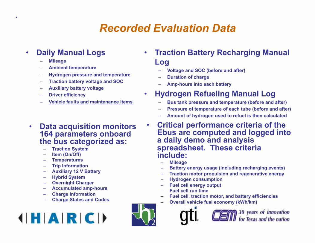
Recorded Evaluation Data
• Daily Manual Logs – Mileage – Ambient temperature – Hydrogen pressure and temperature – Traction battery voltage and SOC – Auxiliary battery voltage – Driver efficiency – Vehicle faults and maintenance items
• Traction Battery Recharging Manual Log
– Voltage and SOC (before and after) – Duration of charge – Amp-hours into each battery
• Hydrogen Refueling Manual Log – Bus tank pressure and temperature (before and after) – Pressure of temperature of each tube (before and after) – Amount of hydrogen used to refuel is then calculated
• Data acquisition monitors 164 parameters onboard the bus categorized as:
– Traction System – Item (On/Off) – Temperatures – Trip Information – Auxiliary 12 V Battery – Hybrid System – Overnight Charger – Accumulated amp-hours – Charge Information – Charge States and Codes
• Critical performance criteria of the Ebus are computed and logged into a daily demo and analysis spreadsheet. These criteria include:
– Mileage – Battery energy usage (including recharging events) – Traction motor propulsion and regenerative energy – Hydrogen consumption – Fuel cell energy output – Fuel cell run time – Fuel cell, traction motor, and battery efficiencies – Overall vehicle fuel economy (kWh/km)

E-Bus Maintenance and Reliability
• Routine Maintenance – Battery deep discharge (once a month) – Battery watering (once a month) – Air brake test (daily)
• Non-routine Maintenance and Reliability Issues – Parking brake shuttle valve plumbing
• Resolved, now working normally
– 12V auxiliary battery failure • Resolved, now working normally
– Mechanical brake overheating • Resolved, now working normally
– Hydrogen recirculation pump controller • Resolved, now working normally
– Low Stack Voltage and Boost Power faults • Replaced fuel cell stack, now working normally
– E-Bus computer failure • Replaced fuel cell stack, now working normally
– Fuel cell leak • Replaced fuel cell stack, now working normally
Developmental Issues are to be expected for prototype vehicles

Vehicle Modeling using PSAT (Powertrain System Analysis Toolkit)
• All electric vehicle – Deep cycle lead-acid
batteries – Advanced state of the art
batteries
• Fuel cell vehicle
• Fuel cell hybrid vehicle – Plug-in fuel cell – Fuel cell dominant hybrid
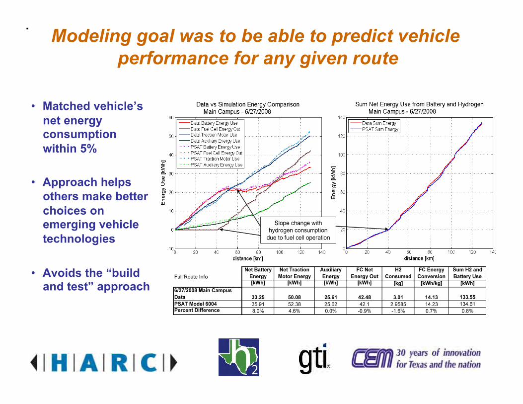
Modeling goal was to be able to predict vehicle performance for any given route
• Matched vehicle’s net energy consumption within 5%
• Approach helps others make better choices on emerging vehicle technologies
• Avoids the “build and test” approach

Bus Maintenance and Storage Facility
• Hydrogen Bus is stored in an indoor, temperature controlled lab
– Serves as our maintenance facility – Fuel cell must be kept above freezing temperatures
• Hydrogen level in lab is constantly monitored – Alarms (audio and visual) will trigger at ¼ of the Lower
Flammability Limit (LFL for hydrogen is 4% by volume in air) • The lab is constantly vented by two exhaust fans
– Fans exceed ventilation requirement of 1 ft3/min/ft2 of floor area (NFPA 55, 6.16.3)
• Lab conforms to NFPA standards – NFPA 52, NFPA 55, and NFPA 70
Hydrogen Gas Monitor Readout (wall-mounted)
Door Placards
Indoor Storage Facility
Alarms
Fan Cut-Off
Hydrogen Gas Sensor (mounted at highest point in the ceiling)

Sponsors and Supporting Partners
• US Department of Energy • US Department of Transportation • Texas H2 Coalition • Houston Advanced Research Center (HARC) • Center for Transportation and the Environment (CTE) • Texas Commission on Environmental Quality (TCEQ) • Texas State Energy Conservation Office (SECO) • Gas Technology Institute • The University of Texas at Austin

Proterra Bus to Arrive in Austin in 2010
35’ Transit Bus Fuel Cell / Plug-in Battery Hybrid Bus Ground-up Design Regenerative Braking 37 Passengers Up to 10 mpg diesel energy equivalent

GTI Advanced Energy Systems
Infrastructure 101for a Growing Hydrogen Market
NHA Conference
4-1-09
“Building Technology Bridges to a Hydrogen Future.”

Discussion for TodayDiscussion for Today
>Why Hydrogen and Fuel Cell Vehiclesy y g>Hydrogen Infrastructure Basics>Fueling infrastructure challenges>Fueling infrastructure challenges>Possible Solutions for growing infrastructure
demanddemand
Building Technology Bridges to a Hydrogen Future 2Building Technology Bridges to a Hydrogen Future 2
Gas Technology InstituteGas Technology Institute
Solving Important Energy Ch ll i
> Contract Research> Program Management
Challenges via:
Program Management> Technical Services> Education and Training
> Over 1,000 patents
Building Technology Bridges to a Hydrogen Future 3Building Technology Bridges to a Hydrogen Future 3
, p> Nearly 500 products commercialized

GTI LocationsGTI Locations
HeadquartersqDes Plaines, IL(a suburb of Chicago)
Strategic Account ManagementNeedham, MA (NGA)
Washington Operations
California Project Development Washington Operations
Washington, DC
GTI/Catoosa Drilling
SpecialistFolsom, CA
Process Research and Evaluation GroupBirmingham, AL
Test FacilityCatoosa, OK (near Tulsa)
Regional OfficeHouston TX
Building Technology Bridges to a Hydrogen Future 4
Houston, TX

Why Hydrogen?Why Hydrogen?
>Recognition that the cost of fuel includes social gcosts
>There are clear private sector benefits to adopting hydrogen and fuel cell technology
>International Auto and Energy Companies are i ti bi b kinvesting big bucks
>$120 oil>Government is on board
Building Technology Bridges to a Hydrogen Future 5Building Technology Bridges to a Hydrogen Future 5

Evolution of the Fuels Industry
Natural
Coal / Oil
Diesel /Gasoline
HydrogenNatural Gas/ BiofuelsCoal / Oil Biofuels
Decarbonization of EnergyDecarbonization of Energy
Building Technology Bridges to a Hydrogen Future 6

Carbon Content of Transportation FuelsCarbon Content of Transportation Fuels
Today’s FuelsDiesel C16H34
Hydrogen
Gasoline C8H18
Propane C3H8
Natural Gas CH4
Building Technology Bridges to a Hydrogen Future 7

Hydrogen PropertiesHydrogen Properties
>Colorless>Odorless>High energy content>High energy content>Not toxic>Highly flammable>Highly flammable>Difficult to Store (small molecule) low liquid
temperaturetemperature>Highly diffuse
Building Technology Bridges to a Hydrogen Future 8Building Technology Bridges to a Hydrogen Future 8

Alternative Production and Storage Methods for Hydrogen Infrastructure
STORAGE & DISTRIBUTION METHODS
PRODUCTION METHODS
S f tElectricity
ElectrolysisCostlyenergy intensive
Leading hydrogen generation method
Compressed H2
Safety spacecost convenience
Natural Gas
Steam Methane Reformers
Auto-Thermal
generation methodPurification needed
Efficiency needs i t
Liquefied H2
Safety energy loss scalability
Hydrocarbon Solids &Residues
Auto ThermalReformers
P ti l O id ti
improvementH2 purification
Industrial applications
Cost stage of technologyweight
Chemical/MetalHydrides
Residues
Oil
Partial Oxidation
Refining Process
Industrial applications requires cheap fuel
By-product refining process
recharging
Pipeline Distance cost
Building Technology Bridges to a Hydrogen Future 9
Quality insufficient for Commercial applications
cost

Why Fuel Cell Vehicles?Why Fuel Cell Vehicles?Performance Conventional Vehicle Fuel Cell Vehicle
Feature
Emissions
Performance and Efficiency
Versatility
Range and ConvenienceRange and Convenience
Cost
Building Technology Bridges to a Hydrogen Future 10

Fuel Cell Cars Here TodayFuel Cell Cars – Here Today
Building Technology Bridges to a Hydrogen Future 11

Today’s Hydrogen Station SpecsToday s Hydrogen Station Specs
Columbia Hydrogen Station Specifications•Daily maximum capacity 120 kg per daykg per day•5000 psi dispensing•7000 psi maximum storage with 66 kg capacity•Passenger vehicle fueling under 5 minutes•Quiet operation – less than 65 dB at 20 feet•Future flexibility possible for multiple fuelsmultiple fuels
Station Capacity: 120 kg/day – Approximately 30 cars/day
Building Technology Bridges to a Hydrogen Future 12
Station Capacity: 120 kg/day Approximately 30 cars/dayPeak Hour Capacity: 5-7 Cars

Basic Hydrogen Station Flow ProcessFlow Process
NaturalGas & Water
Onsite FuelProcessor
HydrogenPurification
OnsiteHigh-Pressure
HydrogenStorage
Water &Electricity
OnsiteElectrolyzer
HydrogenPurification
High PressureHydrogen
High-PressureHydrogen
g
HydrogenDispenserElectricity Electrolyzer Purification
TruckCentral
350 or 700 BarCompression Dispenser
OffsiteH2 Production
TruckHydrogenDelivery
CentralHydrogenProduction
Building Technology Bridges to a Hydrogen Future 13

Typical Cascade Fast-fill Gaseous Storage ConfigurationGaseous Storage Configuration
Building Technology Bridges to a Hydrogen Future 14

On-site Hydrogen StorageOn site Hydrogen Storage
3-bank composite storage assembly ASME vessel configurations
Building Technology Bridges to a Hydrogen Future 15Building Technology Bridges to a Hydrogen Future 15

Cascade Storage Peak Demand ResponseCascade Storage Peak Demand Response
For this example, the storage can meet the demand of eight
Building Technology Bridges to a Hydrogen Future 16
p , g gvehicles fills in succession before “recharging” is required.

H2 Infrastructure Project Timeline Estimate
Infrastructure Project Timeline
Building Technology Bridges to a Hydrogen Future 170 1 yr 2.0 3 yr … 5-8
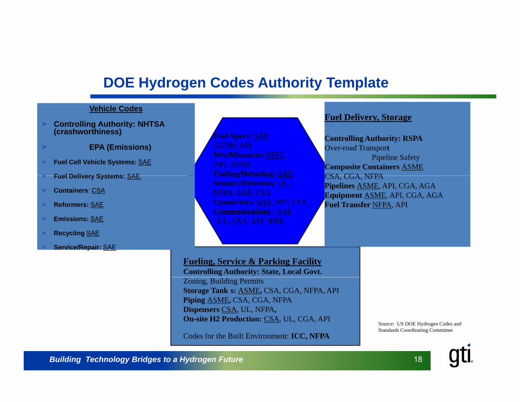
DOE Hydrogen Codes Authority TemplateVehicle Codes
> Controlling Authority: NHTSAFuel Delivery, Storage
> Controlling Authority: NHTSA (crashworthiness)
> EPA (Emissions)
> Fuel Cell Vehicle Systems: SAE
> Fuel Delivery Systems: SAE
Controlling Authority: RSPAOver-road Transport
Pipeline SafetyComposite Containers ASMECSA CGA NFPA
Fuel Specs: SAEASTM, APIWts/Measures: NIST,API, ASMEFueling/Defueling: SAE> Fuel Delivery Systems: SAE,
> Containers: CSA
> Reformers: SAE
> Emissions: SAE
CSA, CGA, NFPAPipelines ASME, API, CGA, AGAEquipment ASME, API, CGA, AGAFuel Transfer NFPA, API
Fueling/Defueling: SAESensors/Detectors: UL,NFPA, SAE, CSAConnectors: SAE, API, CSACommunications : SAEUL, CSA, API, IEEE
> Recycling SAE
> Service/Repair: SAE
Fueling, Service & Parking FacilityControlling Authority: State, Local Govt.Zoning, Building PermitsStorage Tank s: ASME, CSA, CGA, NFPA, APIPiping ASME, CSA, CGA, NFPADispensers CSA, UL, NFPA,On-site H2 Production: CSA, UL, CGA, API
Source: US DOE Hydrogen Codes and
Building Technology Bridges to a Hydrogen Future 18Building Technology Bridges to a Hydrogen Future 18
Codes for the Built Environment: ICC, NFPAStandards Coordinating Committee

Today’s Hydrogen InfrastructureToday s Hydrogen Infrastructure
> Designed for small, demonstration fleets> Not prepared for unscheduled, high-demand loads> Stations require too much lead time and customized
designdesign> High on-site engineering and integration costs> Codes requirements are becoming clearer, but Codes equ e e s a e beco g c ea e , bu
unevenly enforced> Still too expensive, but costs are falling>Physical site limitations for storage configuration (including space, weight, and code restrictions).> Improvements are likely to be incremental
Building Technology Bridges to a Hydrogen Future 19
> Improvements are likely to be incremental

Other Options for pHydrogen Infrastructure
Building Technology Bridges to a Hydrogen Future 20
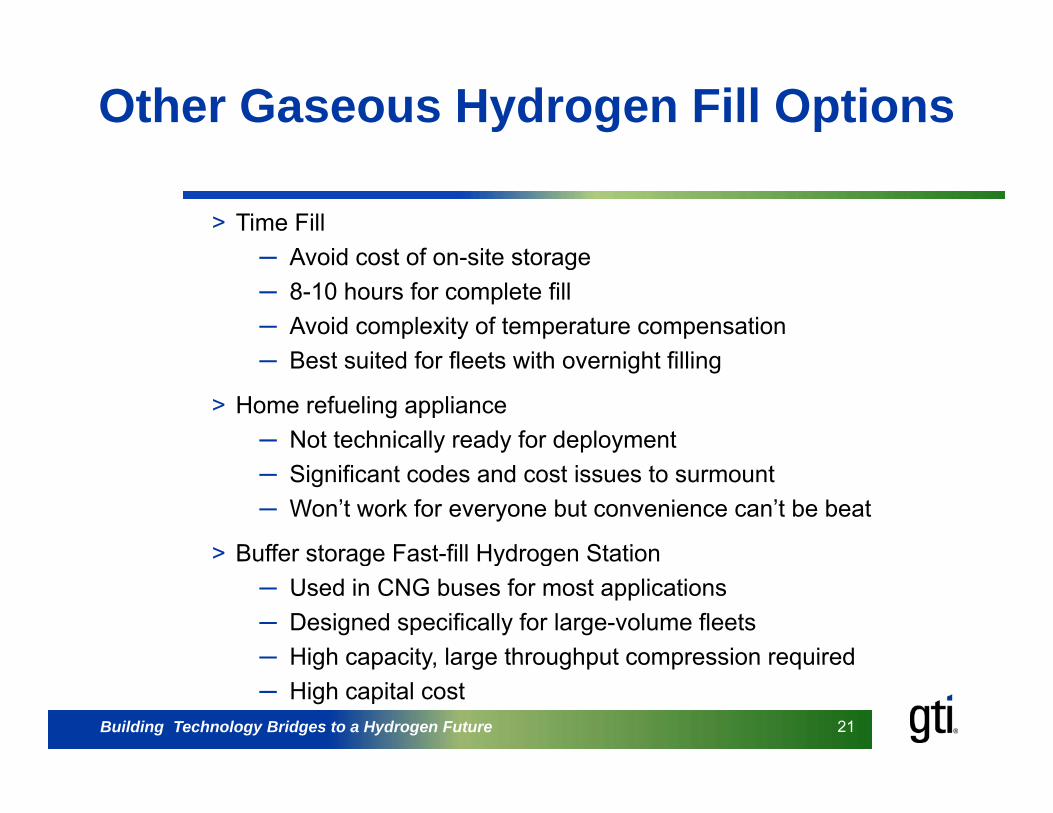
Other Gaseous Hydrogen Fill Options
> Time FillAvoid cost of on site storage─ Avoid cost of on-site storage
─ 8-10 hours for complete fill─ Avoid complexity of temperature compensation
B t it d f fl t ith i ht filli─ Best suited for fleets with overnight filling
> Home refueling appliance─ Not technically ready for deployment─ Significant codes and cost issues to surmount─ Won’t work for everyone but convenience can’t be beat
> Buffer storage Fast-fill Hydrogen StationBuffer storage Fast fill Hydrogen Station─ Used in CNG buses for most applications ─ Designed specifically for large-volume fleets─ High capacity, large throughput compression required
Building Technology Bridges to a Hydrogen Future 21Building Technology Bridges to a Hydrogen Future 21
High capacity, large throughput compression required─ High capital cost

Fleet Fill OptionsFleet Fill Options
Building Technology Bridges to a Hydrogen Future 22
Time-Fill Station for Centrally-located Fleet

Home fueling options are being d l ddeveloped
Building Technology Bridges to a Hydrogen Future 23

On-site Liquid Hydrogen Storage
Building Technology Bridges to a Hydrogen Future 24

Natural gas infrastructure as a Hydrogen inventory management tooly g
>Increased capital cost / decreased marginal cost >Reduction in emissions by eliminating on-road
transportation of productp p>“Real-time” inventory is better achieved>Flexible fuel possibilities (biogas biofuels>Flexible fuel possibilities (biogas, biofuels,
pipeline supply, propane…)>Don’t throw out improvements while waiting on>Don t throw out improvements while waiting on
perfection
Building Technology Bridges to a Hydrogen Future 25Building Technology Bridges to a Hydrogen Future 25
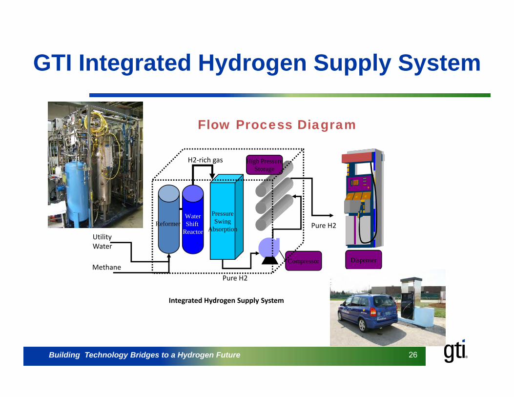
GTI Integrated Hydrogen Supply Systemg y g pp y y
Flow Process Diagram
High PressureStorage
H2‐rich gas
Flow Process Diagram
ReformerPressureSwing
P H2WaterShiftReformer g
Absorption
Compressor Dispenser
Utility Water
Methane
Pure H2Shift Reactor
Pure H2
Integrated Hydrogen Supply System
Building Technology Bridges to a Hydrogen Future 26Building Technology Bridges to a Hydrogen Future 26

Installation layout of Pre-fabH d St tiHydrogen Station
Building Technology Bridges to a Hydrogen Future 27

Integrated Hydrogen Fueling StationIntegrated Hydrogen Fueling Station
Building Technology Bridges to a Hydrogen Future 28

For more information:
Brian WeeksPhone: 281 313-9775b i k @ t h [email protected]
Building Technology Bridges to a Hydrogen Future 29