Test up to ultimate limit state and failure of innovative ...framcos.org/FraMCoS-6/4.pdf · The...
8
1 INTRODUCTION 1.1 The Preflex beam The Belgian engineer, A. Lipski, with assistance of Professor L. Baes from the Université Libre de Bruxelles (Baes and Lipski, 1957) invented the sys- tem of the precambered composite steel-concrete beam, initially known by the patent name “Preflex beam”. The first project using this type of beams dates back to 1951. The two best-known structures are the Southern Tower (Tour du Midi) and the Ber- laymont Building, both in Brussels (Belgium). The typical construction sequence of a prebended beam is as follows (see Figure 1): a. In the plant, setup a steel I-girder, with a pre- camber, supported at each end. b. Prebend the steel girder by applying two concentrated loads at one-quarter and three- quarters of the span. c. Cast the 1 st phase concrete (C50/60) at the level of the bottom flange of the steel girder while keeping in place the loads of the pre- bending phase of the girder. d. Two days after casting the concrete, remove the prebending loads. As a result, the beam goes up, the precamber becomes smaller than the original precamber and the concrete is now subjected to compression. e. Cast the 2 nd phase concrete on site. a b c d e Figure 1. Construction steps of a prebended beam. Figure 2. Prebending of the steel girder (step b and formwork assembly before step c). Test up to ultimate limit state and failure of innovative prebended steel- VHPC beams for railway bridges in France S. Staquet BATir, Université Libre de Bruxelles, Brussels, Belgium F. Toutlemonde Structures Laboratory, French Public Works Research Institute LCPC, Paris, France ABSTRACT: Experimental validation of a possibly attractive extension of the pre-bended composite beams technique, first applied in Belgium as “Preflex”, was carried out. Very high performance concrete (C80/95) was used for potential advantages of low delayed strains and high tensile strength. A major issue of the pro- gramme consisted in validating a design method for the serviceability limit state (SLS) linked to the cracking of the concrete and for the ultimate limit state (ULS) corresponding to an instability (warping) or to yielding of the steel girder. Detailed results of the global response of two 13m-long beams up to ultimate limit state and failure are analyzed in conjunction with deflection measurements. The ultimate limit state computation based on the strength and elastic stability is always controlled by the serviceability limit state for this kind of structures.
Transcript of Test up to ultimate limit state and failure of innovative ...framcos.org/FraMCoS-6/4.pdf · The...
1 INTRODUCTION
1.1 The Preflex beam The Belgian engineer, A. Lipski, with assistance of Professor L. Baes from the Université Libre de Bruxelles (Baes and Lipski, 1957) invented the sys-tem of the precambered composite steel-concrete beam, initially known by the patent name “Preflex beam”. The first project using this type of beams dates back to 1951. The two best-known structures are the Southern Tower (Tour du Midi) and the Ber-laymont Building, both in Brussels (Belgium). The typical construction sequence of a prebended beam is as follows (see Figure 1):
a. In the plant, setup a steel I-girder, with a pre-
camber, supported at each end. b. Prebend the steel girder by applying two
concentrated loads at one-quarter and three-quarters of the span.
c. Cast the 1st phase concrete (C50/60) at the level of the bottom flange of the steel girder while keeping in place the loads of the pre-bending phase of the girder.
d. Two days after casting the concrete, remove the prebending loads. As a result, the beam goes up, the precamber becomes smaller than the original precamber and the concrete is now subjected to compression.
e. Cast the 2nd phase concrete on site.
a
b
c
d
e
Figure 1. Construction steps of a prebended beam.
Figure 2. Prebending of the steel girder (step b and formwork assembly before step c).
Test up to ultimate limit state and failure of innovative prebended steel-VHPC beams for railway bridges in France
S. Staquet BATir, Université Libre de Bruxelles, Brussels, Belgium
F. Toutlemonde Structures Laboratory, French Public Works Research Institute LCPC, Paris, France
ABSTRACT: Experimental validation of a possibly attractive extension of the pre-bended composite beams technique, first applied in Belgium as “Preflex”, was carried out. Very high performance concrete (C80/95) was used for potential advantages of low delayed strains and high tensile strength. A major issue of the pro-gramme consisted in validating a design method for the serviceability limit state (SLS) linked to the cracking of the concrete and for the ultimate limit state (ULS) corresponding to an instability (warping) or to yielding of the steel girder. Detailed results of the global response of two 13m-long beams up to ultimate limit state and failure are analyzed in conjunction with deflection measurements. The ultimate limit state computation based on the strength and elastic stability is always controlled by the serviceability limit state for this kind of structures.

Due to steel-concrete bond, which makes it possible to consider the cross-section as composite, the con-crete of 1st and 2nd phases significantly increase the stiffness of the composite beam as compared to the stiffness of the steel girder alone. Provided the con-crete of the bottom flange remains subjected to com-pression even during the application of service loads, the requirement of no cracking in the concrete is sat-isfied. The design principles for the service loads are partly based on the class II type of BPEL (BPEL, 1999) implying no decompression in concrete under frequent service load combinations and a maximum concrete tensile stress limited to the actual concrete tensile strength under rare service load combina-tions. The design criteria for the ultimate limit state (ULS) correspond to an instability (warping) of the steel profile or to yielding of the steel girder upper flange. The Preflex system has been particularly suc-cessful in Belgium because it allows long spans with a minimal construction depth and offers excellent fire resistance (Staquet et al., 2004). It is presently mainly used in Belgium for railway bridges due to its high fatigue performance (first verified experimen-tally by Verwilst, 1953).
1.2 Research significance The aim of the research program that has been car-ried out at LCPC in the framework of the French National Project MIKTI was to extend the system of the Preflex beam to Very High Performance Con-crete (VHPC) and to give background for further updating of the Eurocode 4 (EN 1994-2) to the de-sign of this kind of structure. Actually, the concrete grade which has been used until now is lower or equal to C50/60 whereas the average compressive strength at 28 days of the concrete in this research is 110 MPa. In the comparison to the present realiza-tions coming from the Belgian precast industry, the main advantage of using VHPC with silica fume is to reduce the prestressing losses of the system thanks to a significant decrease of the creep defor-mations, as predicted by Eurocode (EN 1992-2:2005) together with the possibility to optimize the beam weight and its serviceability domain. Applica-tions might concern French Railways Bridges, where stiffness has to be maintained or increased, due to high speed train requirements, with maintained clearance and reduced beam inertia (accounting for ballast between the rails and the bridge structure). A first theoretical step developed the updated back-ground of these beams design, relatively to delayed strains of concrete and their effects (Mannini, 2001). This development was confirmed by research work conducted in Belgium for prebended U-shaped Bridges (Staquet & Espion, 2005). Then, the interest of VHPC in optimizing the 1st phase concrete dead-weight and the global stiffness was confirmed. Con-sequently, it was decided to carry out an experimen-
tal investigation of long-term performance under dead and fatigue loads and behaviour up to ultimate limit state and failure of VHPC-prebended beams, mainly aiming to validate the scientific method for taking concrete creep into account. Beside data of concrete delayed effects inducing specific monitor-ing (Staquet et al. 2006), the fatigue performance and safety of fatigue design provisions were vali-dated by this experimental program (Toutlemonde & Staquet, 2007). The present paper focuses on vali-dating a design method for the serviceability limit state (SLS) linked to cracking of the concrete and for the ultimate limit state (ULS) corresponding to an instability (warping) or to yielding of the steel girder.
2 EXPERIMENTAL INVESTIGATIONS
2.1 Steps of the experimental program The construction stages a to d (Figure 1) were car-ried out at LCPC on two factory-made steel girders HEB 360, 13m-long, using a specially designed self levelling (Roussel et al., Staquet & Toutlemonde, 2006) VHPC. The cross section of the beams illus-trated on Fig. 3 shows that the thickness of the con-crete situated below the bottom flange of the steel girder was only 55 mm. Moreover, in addition to the longitudinal passive reinforcements (diameter 12 mm), ribbed stirrups (diameter 8 mm) were dis-posed every 15 cm along the beam and steel square ribs (25 x 25 x 200 mm) were welded to the bottom flange of the steel girder every 45 cm (Fig. 4). Di-mensions of the ribs were defined as usual for taking all the design shear stresses at steel lower flange – concrete interface. As usually realized, stirrups are fixed across the steel profile web, which also fa-vours regular stress transfer between concrete and steel, ensuring the desired composite behaviour. Figure 3. Cross section of the prebended beams tested (dimen-sions in mm).

Two days after concrete casting, the prestressing was transferred by releasing the prebending loads (145.2 kN for beam P1 and 137.5 kN for beam P2) initially applied by two jacks at one quarter and at three quarters of the span (Fig. 5). Two months after, the beams were submitted to permanent loads (40 kN applied by lead masses, representing the load of the upper concrete deck, superstructures and ballast). After 4 months, live loads representative of railway traffic were applied: 1000 cycles representing the ef-fect of trains possibly transiting once a year (half UIC conveys), then one or two million cycles corre-sponding to more frequent heavy trains. The deflec-tion was monitored for more than 8 months as well as numerous complementary strain measurements. Mechanical characterization (Young’s modulus), creep and shrinkage tests were also performed so that a correct analysis of the structural behaviour of the prebended beams can be done, focusing on the steel-concrete behaviour, and taking advantage of low delayed deformations of VHPC. Finally the beams were tested up to failure for quantifying their safety margin under service and ultimate loads, and checking the accuracy of the design predictions. Figure 4. Ribbed stirrups (A) every 15 cm along the beam and steel square ribs (B) every 45 cm. Figure 5. Transfer of prestressing to the composite beam at 48 hours of concrete age.
2.2 First phase VHPC mechanical characteristics Optimization of the cross-section required using VHPC (C80/95) for the 1st phase concrete. More-over, transfer of the prebending only 48 hours after casting required strength at least equal to 55 MPa at 2 days, leading to a ratio of about 40 % between the maximal compressive stress applied at 2 days and the average compressive strength, which corre-sponds to the practical current ratio. Self compacting properties were required for the beam realization, due to congested areas under the lower steel flange. The feasibility of this optimization was demon-strated (Staquet & Toutlemonde 2006). Mechanical characteristics of VHPC were measured carefully, under different standard and realistic conditions, for further analysis of the rigidity evolution of the beams. It is noticeable that, even though the cement paste content of this self-levelling VHPC is quite important, the delayed strains amplitude is rather small, due to the silica fume content. These strains are correctly estimated by CEB-FIP 1999 model for creep of specimens loaded at 2 days, and by EN 1992-2 model for creep of specimens loaded at 28 days. Table 1 shows the evolution of the VHPC me-chanical properties: fc, average compressive strength; ft, average splitting tensile strength; E, av-erage modulus of elasticity, determined on cylinders 11/22 cm exposed to 40 % of relative humidity and 20°C at one day of age. The E value at 168 days is slightly lower than the one at 100 days, explained by an effect of rather severe drying conditions. Table 1. VHPC mechanical properties of the cylinders 11/22 exposed to 40% RH and 20 °C after 1 day of concrete age
Age (d) fc (MPa) ft (MPa) E (GPa) 2 71.5 - 38.2 7 87.8 4.4 40.6 28 99.3 4.5 42.8 56 103.1 - 43.4 100 103.3 - 43.5 168 106.1 5.6 43.3
2.3 Loading up to failure
The estimation of the cracking load (average stress equal to about 1.5 ft in the whole 1st phase concrete: 8.4MPa), the warping load for a free span of 6 m (between application points of the loads by the jacks, Fig. 6) and the yield load of the upper flange of the steel girder (fy: 420 N/mm²) by neglecting the concrete participation, provided the following theoretical values of the load at each jack (EN 1993): 93 kN, 336 kN and 410 kN respectively. The tests were carried out in 3 phases (Fig. 7 and 8): up to 115 kN then unloading; up to 250 kN (3/4 of the warping theoretical load or 60 % of the theoretical yield load) then unloading; and loading up to failure.
A
B

Figure 6. Static loading up to failure for the two beams. Figure 7: Loading sequence up to failure of Beams P1 and P2. Figure 8: View of loading of Beam P2.
Test up to failure
0255075
100125150175200225250275300325350375400
0 1 2 3 4 5 6 7 8 9 10 11 12
time (h)
Load P (kN)
Beam P2Beam P1
P2 Max:386kNP1 Max:394kN

The value of 115 kN is considered as an excess value of the design service load which is related to the damage occurrence in the concrete flange (stabi-lized cracking pattern) and the theoretical value of 336 kN corresponds to the ultimate limit state (ULS) loading value. The table 2 shows the extreme first phase concrete stress values under permanent loads computed by using the CEB MC 90 model code in its version 99 (fib, 1999) for the prediction of creep and shrinkage of the VHPC. The stress values for the beam P1 are put in italic in Table 2 because, due to an extra-severe loading leading to an irrecover-able cracking that was applied on Beam P1 before the fatigue test and the test up to failure, the stress state of concrete is different from these computed values in some parts of this beam. Table 2. Extreme stress computed values in concrete before the test up to failure (negative value in compression) Stress value in the 1st phase concrete
(MPa)
Bottom fiber
Upper fiber
Average
Beam P1 -2.9 +1.8 -0.55 Beam P2 -2.8 +1.7 -0.6
2.4 Results and discussion.
According to the loading configuration shown in the figure 9, the apparent bending stiffness can be de-termined from the deflection f at mid-span and the global applied load 2P, using the following equation:
kαf
2P48
)4aa(3lEI22
=−
= where f
2Pk =
Figure 9: Loading configuration during test up to failure.
The static bending stiffness EI of the steel girder
alone is 90,700 kN.m² whereas the static bending stiffness of the composite beam corresponding to a full concrete contribution (with instantaneous modu-lar ratio) is 152,700 kN.m², the concrete correspond-ing to one third of the global stiffness. The values of the stiffness k reported in Table 3 were obtained from a linear regression of the experimental relation load-deflection at mid-span for each loading and unloading phase in the range of 0 to 20 kN. As the P1 beam had been submitted to an extra-severe load-ing leading to irrecoverable cracking, its static bend-ing stiffness at the beginning of the test was lower than the one of the P2 beam.
Table 3. Static bending stiffness of the tested beams during the test up to failure (L:loading; U: unloading). P1 k (kN/mm) EI (kN.m²) Variation L 0-115 kN 7.12 125,000 U 115 kN-0 6.04 106,000 -15.2 % L 0-250 kN 6.96 123,000 -2.2 % U 250 kN-0 5.56 98,000 -21.9 % P2 k (kN/mm) EI (kN.m²) Variation L 0-115 kN 7.58 133,000 U 115 kN-0 6.28 111,000 -17.2 % L 0-250 kN 7.30 129,000 -3.7 % U 250 kN-0 5.48 96,000 -27.7 % After having reached the SLS load (115 kN), the bending stiffness loss which was obtained from the experimental relation force-deflection in the loading phase up to 250 kN, was only 2% for Beam P1 and 4% for Beam P2. The reduction of the static bending stiffness after having loaded the beam up to 250 kN and determined in the unloading phase was 22% for Beam P1 and 28% for Beam P2 and is less than 10% higher than stiffness of the steel alone. A significant reduction of the bending stiffness in the range of 15% to 17% was also obtained in the unloading phase from 115 kN. The bending stiffness was sub-sequently fully recovered after having completely unloaded the beam because the level of compressive stresses was high enough to close the cracks in the concrete flange of the two beams. The observation of the first cracking visible on the bottom surface of the concrete flange around mid-span appeared at a load of 40 kN for Beam 1 and 85 kN for Beam 2 or at a bending moment of 100 kN.m and 212 kN.m re-spectively. As the load increased up to the SLS value, the crack network extended until it reached a pattern in close relation with the steel mesh of rein-forcement: ribbed stirrups every 15 cm, visible on lateral and upper surfaces along the beam and steel square ribs welded to the bottom flange of the steel girder, visible on the bottom surface every 45 cm along the beam (Fig. 10). The maximal crack open-ing reaches 0.15 mm under 115 kN and the crack pattern was stabilised, uniformly distributed between the two concentrated loads at this loading value. Figure 10: View of the cracking pattern.
L
a a P P
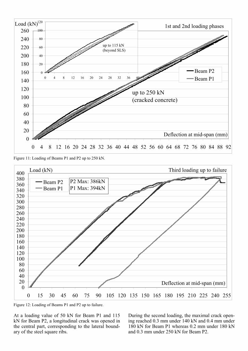
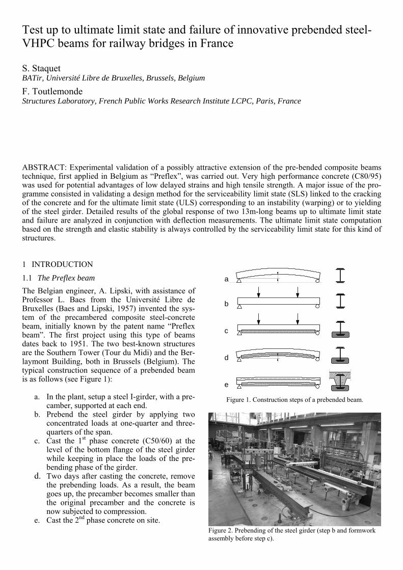
Figure 11: Loading of Beams P1 and P2 up to 250 kN. Figure 12: Loading of Beams P1 and P2 up to failure. At a loading value of 50 kN for Beam P1 and 115 kN for Beam P2, a longitudinal crack was opened in the central part, corresponding to the lateral bound-ary of the steel square ribs.
During the second loading, the maximal crack open-ing reached 0.3 mm under 140 kN and 0.4 mm under 180 kN for Beam P1 whereas 0.2 mm under 180 kN and 0.3 mm under 250 kN for Beam P2.
1st and 2nd loading phases
020406080
100120140160180200220240260
0 4 8 12 16 20 24 28 32 36 40 44 48 52 56 60 64 68 72 76 80 84 88 92
Deflection at mid-span (mm)
Load (kN)
Beam P2Beam P1
up to 250 kN(cracked concrete)
0
20
40
60
80
100
120
0 4 8 12 16 20 24 28 32 36 40
up to 115 kN(beyond SLS)
Third loading up to failure
020406080
100120140160180200220240260280300320340360380400
0 15 30 45 60 75 90 105 120 135 150 165 180 195 210 225 240 255
Deflection at mid-span (mm)
Load (kN)
Beam P2Beam P1
P2 Max: 386kNP1 Max: 394kN
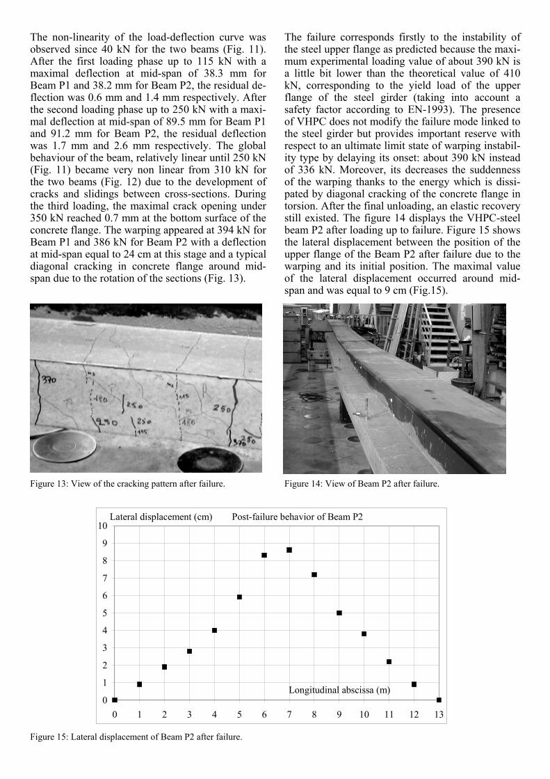
The non-linearity of the load-deflection curve was observed since 40 kN for the two beams (Fig. 11). After the first loading phase up to 115 kN with a maximal deflection at mid-span of 38.3 mm for Beam P1 and 38.2 mm for Beam P2, the residual de-flection was 0.6 mm and 1.4 mm respectively. After the second loading phase up to 250 kN with a maxi-mal deflection at mid-span of 89.5 mm for Beam P1 and 91.2 mm for Beam P2, the residual deflection was 1.7 mm and 2.6 mm respectively. The global behaviour of the beam, relatively linear until 250 kN (Fig. 11) became very non linear from 310 kN for the two beams (Fig. 12) due to the development of cracks and slidings between cross-sections. During the third loading, the maximal crack opening under 350 kN reached 0.7 mm at the bottom surface of the concrete flange. The warping appeared at 394 kN for Beam P1 and 386 kN for Beam P2 with a deflection at mid-span equal to 24 cm at this stage and a typical diagonal cracking in concrete flange around mid-span due to the rotation of the sections (Fig. 13). Figure 13: View of the cracking pattern after failure. Figure 15: Lateral displacement of Beam P2 after failure.
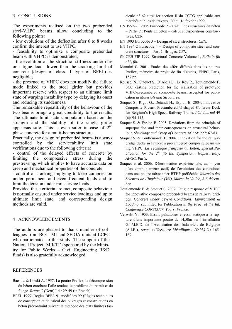
The failure corresponds firstly to the instability of the steel upper flange as predicted because the maxi-mum experimental loading value of about 390 kN is a little bit lower than the theoretical value of 410 kN, corresponding to the yield load of the upper flange of the steel girder (taking into account a safety factor according to EN-1993). The presence of VHPC does not modify the failure mode linked to the steel girder but provides important reserve with respect to an ultimate limit state of warping instabil-ity type by delaying its onset: about 390 kN instead of 336 kN. Moreover, its decreases the suddenness of the warping thanks to the energy which is dissi-pated by diagonal cracking of the concrete flange in torsion. After the final unloading, an elastic recovery still existed. The figure 14 displays the VHPC-steel beam P2 after loading up to failure. Figure 15 shows the lateral displacement between the position of the upper flange of the Beam P2 after failure due to the warping and its initial position. The maximal value of the lateral displacement occurred around mid-span and was equal to 9 cm (Fig.15). Figure 14: View of Beam P2 after failure.
Lateral displacement (cm) Post-failure behavior of Beam P2
0
1
2
3
4
5
6
7
8
9
10
0 1 2 3 4 5 6 7 8 9 10 11 12 13
Longitudinal abscissa (m)
3 CONCLUSIONS The experiments realised on the two prebended steel-VHPC beams allow concluding to the following points: - low evolutions of the deflection after 6 to 8 weeks confirm the interest to use VHPC; - feasability to optimize a composite prebended beam with VHPC is demonstrated; - the evolution of the structural stiffness under rare or fatigue loads lower than the cracking limit of concrete (design of class II type of BPEL) is negligible; - the presence of VHPC does not modify the failure mode linked to the steel girder but provides important reserve with respect to an ultimate limit state of warping instability type by delaying its onset and reducing its suddenness. The remarkable repeatitivity of the behaviour of the two beams brings a great credibility to the results. The ultimate limit state computation based on the strength and the stability of the single girder appearsas safe. This is even safer in case of 2nd phase concrete for a multi-beams structure. Practically, the design of prebended beams is always controlled by the serviceability limit state verifications due to the following criteria: - control of the delayed effects of concrete by limiting the compressive stress during the prestressing, which implies to have accurate data on creep and mechanical properties of the concrete; - control of cracking implying to keep compression under permanent and even frequent loads and to limit the tension under rare service loads. Provided these criteria are met, composite behaviour is normally ensured under service loadings and up to ultimate limit state, and corresponding design methods are valid.
4 ACKNOWLEDGEMENTS
The authors are pleased to thank number of col-leagues from BCC, MI and SFIOA units at LCPC who participated to this study. The support of the National Project ‘MIKTI’ (sponsored by the Minis-try for Public Works – Civil Engineering R&D funds) is also gratefully acknowledged.
REFERENCES
Baes L. & Lipski A. 1957. La poutre Preflex, la décompression du béton enrobant l’aile tendue, le problème du retrait et du fluage. Revue C (Gent) I-4 : 29-49 (in French).
BPEL 1999. Règles BPEL 91 modifiées 99 (Règles techniques de conception et de calcul des ouvrages et constructions en béton précontraint suivant la méthode des états limites) fas-
cicule n° 62 titre 1er section II du CCTG applicable aux marchés publics de travaux, JO du 16 février 1999.
EN 1992-2 : 2005 Eurocode 2 – Calcul des structures en béton – Partie 2 : Ponts en béton – calcul et dispositions construc-tives, CEN.
EN 1993 Eurocode 3 – Design of steel structures, CEN. EN 1994-2 Eurocode 4 – Design of composite steel and con-
crete structures – Part 2: Bridges, CEN. fib-CEB-FIP 1999, Structural Concrete Volume 1, Bulletin fib
n°1, fib. Mannini C. 2001. Etudes des effets différés dans les poutres
Preflex, mémoire de projet de fin d’études, ENPC, Paris, 157 pp.
Roussel N., Staquet S., D’Aloia L., Le Roy R., Toutlemonde F. SCC casting prediction for the realization of prototype VHPC-precambered composite beams, accepted for publi-cation in Materials and Structures.
Staquet S., Rigot G., Detandt H., Espion B. 2004. Innovative Composite Precast Precambered U-shaped Concrete Deck for Belgium’s High Speed Railway Trains. PCI Journal 49 (6): 94-113.
Staquet S. & Espion B. 2005. Deviations from the principle of superposition and their consequences on structural behav-iour. Shrinkage and Creep of Concrete ACI SP 227: 67-83.
Staquet S. & Toutlemonde F. 2006. Innovation for the railway bridge decks in France: a precambered composite beam us-ing VHPC. La Technique française du Béton, Special Pu-blication for the 2nd fib Int. Symposium, Naples, Italy, AFGC, Paris.
Staquet et al. 2006. Détermination expérimentale, au moyen d’un contraintemètre actif, de l’évolution des contraintes dans une poutre mixte acier-BTHP préfléchie. Journées des Sciences de l’Ingénieur (JSI), Marne-la-Vallée, 5-6 décem-bre.
Toutlemonde F. & Staquet S. 2007. Fatigue response of VHPC for innovative composite prebended beams in railway brid-ges. Concrete under Severe Conditions: Environment & Loading, submitted for Publication in the Proc. of the Int. Conference CONSEC07, Tours, France.
Verwilst Y. 1953. Essais pulsatoires et essai statique à la rup-ture d’une importante poutre de 14,50m sur l’installation G.I.M.E.D. de l’Association des Industriels de Belgique (A.I.B.), revue « l’Ossature Métallique » (O.M.) 3 : 165-169.