TEST EQUIPMENT - South Dakota School of Mines and...
22
TEST EQUIPMENT TRUE RMS DIGITAL MULTIMETER I 72-410A OPERATION MANUAL
Transcript of TEST EQUIPMENT - South Dakota School of Mines and...

TEST EQUIPMENT
TRUE RMSDIGITAL
MULTIMETERI
72-410A
OPERATION MANUAL

TITLES
CONTENTS
PAGES
1. ~Ft()I>lJ<:1rI()~ ----------------------------------------------------------------------- 3
2. SAFE1rY INF()FtMA1rI()N2-1. Warning and <:aution ---------------------------------------------------------------- 42-2. International electrical symbols ---------------------------------------------------- 42-3. Injput terminals ----------------------------------------------------------------------- 42-4. Line voltage selection and fuse ratings ------------------------------------------- 5
3. SPE<:IFI<:A1rI()~S3-1. General sjpecification -----------------------------------------------------------------73-2. Injput terminals and limits -----------------------------------------------------------83-3. 1rruerms. -------------------------------------------------------------------------------8
4. ()PEFtA1rmG mS1rFtlJ<:1rI()~S
4-1. Zero adjustment -----------------------------------------------------------------------94-2. Injput overload jprotection ------------------------------------------------------------94-3. <:hanging injput jpower configuration ---------------------------------------------104-4. Power switch -------------------------------------------------------------------------104-5. Measuring voltage -------------------------------------------------------------------104-6. Measuring current--------------------------------------------------------------------114-7. Measuring resistance ---------------------------------------------------------------144-8. Measuring frequency ---------------------------------------------------------------154-9. lrransister hFE test ------------------------------------------------------------------164-10. I>iode test -----,..---------------------------------------------------------------------164-11. <:ontinuity test ----------------------------------------------------------------------174-12. Hold function -----------------------------------------------------------------------174-13. Handle -------------------------------------------------------------------------------17

5. RESOLUTION AND ACCURACY -----------------------:.--------------------------18
6. MAINTENANCE6-1. Introduction --------------------------------------------------------------------------196-2. Fuse replacement --------------------------------------------------------------------19
7. ACCESSORIES -------------------------------------------------------------------------19
8. MEMO ------------------------------------------------------------------------------------2()

1. INTRODUCTION
.ii.. @ --:, \..JBBaB' '.~. .=.: " -;~:M_ _ ....~ E':OOE'rTIO iSOTI5Co:::J... -. -=-- .... -
FIG 1-1o Your rEZD model 72-410A is a portable, bench type
digitalmultimeter with a 4+ digit light-emittingdiode(LED).
o The 72-410A can make hFE measurements, diodemeasurements,frequency measurements and continuitymeasurements in addition to the usual DMM measurement- AC/DC volts, AC/DC current and resistance.
o TRUE RMS MEASUREMENT OF AC SIGNALS:TRUE RMS measurement is the only accurate way todirectly measure ac sigals that are not noise-freepure sine waves. The 72-410A measures ac voltage
frequencies up to 50KHz.
o SAFEY AND EMC : Approval at TUVThis meter has been designed and tested in accordancewith safety and EMC.- SAFETY: EN6101O-1 Approval at TDv- EMC REGULATIONS: EN50081-1, EN55022, class B
EN50082-1, IEC801-2,3,4- overvoltage cat. II- pollution deg. II
3

2. SAFETY INFORMATION
WARNINGREAD nMULTIMETER SAFETY" BEFORE USINGTHIS METER.
This meter has been designed and tested in accordancewith IEC publication.To ensure that the meter is used safety, follow allsafety and operating instructions in this manual.If the meter is not used as described in this manualthe safety features of the meter might be impaired.
2-1. "WARNING" and "CAUTION" ;"WARNING" is used for conditions and actions that,pose hazards to the user, the word "CAUTION" isused for conditions and actions that may damageyour meter
2-2. INTERNATIONAL ELECTRICAL SYMBOLS& DANGEROUS VOLTAGE .-L GROUND
AC-ALTERNATING & IMPORTANT SAFETY~ CURRENT INFORMATION IN MANUAL
--- DC-DIRECT CURRENT ICJI DOUBLE INSULATION
TABLE 2-1.
2-3. INPUT TERMINALS,To take a measurement, correctly connect the testlead with the prober input terminals. As indicated(positive / negative) the red color of inputterminal allow you to have easy operation.See FIG 2-1.
4

CD lOA
®COM
@VQHz"* .'1»@rnA@Socket
Amperes Input TerminalFor current measurements(AC or DC) up tolOA continuous when the function selectorswitch is in the lOA position.
Common Tertninal(Ground)Return terminal for all measurements.Do not apply more than IOOOV between the(com) terminal and earth ground.(Black color)
Volts, Ohms, Continuity, Frequency, Diodetest input terminal (Red color)
rnA input Terminal.
Transistor hFE input Terminal
WARNINGTO AVOID ELECTRICAL SHOCK OR DAMAGE TO THEMETER. DO NOT APPLY MORE THAN 1000V BETWEENCOM TERMINAL AND EARTH GROUND.TO AVOID ELECTRICAL SHOCK. USE CAUTION WHENWORKING ABOVE 60VDC OR 30VAC RMS, SUCH VOLTAGESPOSE A SHOCK HAZARD.
2-4. LINE VOLTAGE SELECTION AND FUSE RATINGS.
VOLTAGE FUSE POWER MAX
I03V -126V(50Hz/60Hz) F O.5A 250V lOW
206V - 252V(50Hz/60Hz) F O.25A 250V lOW
TABLE 2-2.
o Select the proper function and range for yourmeasurements.
o Disconnect the live test lead before disconnecting thecommon test lead.
5

o Do not use the meter if the meter or test lead lookdamaged,or if you suspect that the meter is notoperating properly;
oTum off power to the circuit under test before cutting,unsoldering or breaking the circuit.Small amounts of current can be dangerous.
o When using the probes, keep your finger behind thethe fmger guards on the probes.
... • IIlII......o '!I l1li
FIG 2-1. 72-410A FRONT VIEW
® -=-=-=v VOLTS DCIhFE @ Q RESISTANCE(J) ----v VOLTSAC @ +r.'») DIODE AND CONTINUITY
® ---A AMPERES DC @ FREQ FREQUENCY
® ----A AMPERESAC ® <D POWER ON/OFF SWITCH
TABLE 2-3. FUNCTION SELECTED BY SWITCH
@200rnV Q 200nV,200 QRANGE @mJVrnAkQ OCIOlN/AC7ilV,JIDnA,JIOKQRANGE@2VrnAKQ 2V,2mA,2K QRANGE @IOAMQ IO~QRANGE
@WVrnAKQKHz 2OV~K Q,WKHzRANGE @hfE hFE TEST@ :mVrnAkQ KHz :roY,IDnA,XXlK Q,nlKHzRANGE @HOill DATA HOLD FUNCTION
TABLE 2-4. RANGE SELECTED BY SWITCH
6

3. SPECIFICATIONS.0NOTE:After turning on power, please allow a pre-heating
period of as long as some 15 minutes before use.
3-1.GENERAL SPECIFICATION.o 4 ~ Digit: 20,000 count LED
o Measurement rate: 2.5 times/sec
o Protection for input overload
o Dual slop integration NO converter system
o Over range indication: Most-significant digit flickered
o Long-term calibration stability: one year
o Temperatures: Operating: 0 'C ~ 50'C (below 80%)
Storage: -20"C ~ 60'C (below 70%)
Guaranted accuracy : 23 'C + 5 'C
o Line voltage: 103V ~ 126V, 50Hz/60Hz
206V ~ 252V, 50Hz/60Hz
o Power consumption: 10 Wmax
o Dimensions: 25.0cm 9.25cm 25.1cm (See FIG 3-1.)
o Weight: 1.50kg
]
~
....... I-
~f-
'" ~. o· I.... ...,
b~'oII.' Or- -. ~-O!I ~a;I -O'l
-0 1a;I Iloia;I 10
~,.. 10.,; cO
1'"' 10tofrotOr
@O@4'0 ~ JU@J1§l
I
FIG 3-1. DIMEMSIONS
7

3-2. INPUT TERMINAL AND LIMITS
FUNCTION INPUT TERMINAl MINIMUM DISPLAY MAXMUM DISPLNI MAXIMUM INPUTREADING READINGV VQHz COM O.OlmV HXXNCD,7jlVAC 1<mVDC, 7jlVAC
lOA IDA COM O.oolA lOA 10N250VrnA rnA COM O.O)lmA 2(ffinA 21IDnAI250VQ VQHz COM 0.1 Q 20MQ fffNAO OC(lmin)
Hz VQHz COM 1Hz 200KHz 250VAOOCCONIlNUllY VQHz COM 600VAC/DC
DIODE VQHz COM (ffiVAO DC(lmin)
hFE SOCKET
TABLE 3-1. (* AC VALUE IS RMS VALUE)
3-3. TRUE RMSIn order to compare dissimilar waveforms, calculateohm's law statements or power relationships, you mustknow the effective value of a signal.If it is a dc signal, the effective value equals the dclevel. If the signal is ac, however, we have to use theroot mean square or rms value. The rms value of an accurrent or ac voltage is defined as being numericallyequal to the dc current or voltage that produces thesame heating effect in a given resistance that the accurrent or voltage produces.In the past, average responding converters were thetype of converter most widely used. theoretically, therms value of a pure sine wave is 1/2~ of the peak value
and the average value is 2/ TT of the peak value.Since the meters converted to the average value, the
value was 1/2 ~ --;- 2/TT = 1.11 of the average value whenmeasuring a sine wave. Most meters used an averageresponding converter and multiplied by 1.11 to presenttrue rms measurements of sine waves. As the signalbeing measured deviated from a pure sine waves,
8
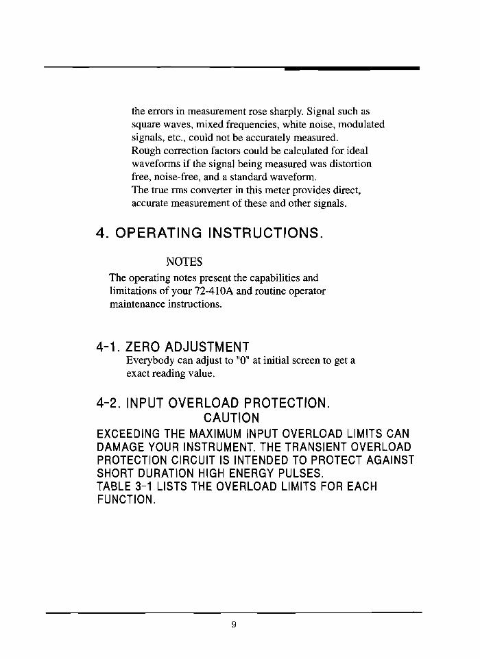
the errors in measurement rose sharply. Signal such assquare waves, mixed frequencies, white noise, modulatedsignals, etc., could not be accurately measured.Rough correction factors could be calculated for idealwaveforms if the signal being measured was distortionfree, noise-free, and a standard waveform.The true rms converter in this meter provides direct,accurate measurement of these and other signals.
4. OPERATING INSTRUCTIONS.
NOTESThe operating notes present the capabilities andlimitations of your 72-410A and routine operatormaintenance instructions.
4-1. ZERO ADJUSTMENTEverybody can adjust to "0" at initial screen to get aexact reading value.
4-2. INPUT OVERLOAD PROTECTION.CAUTION
EXCEEDING THE MAXIMUM INPUT OVERLOAD LIMITS CANDAMAGE YOUR INSTRUMENT. THE TRANSIENT OVERLOADPROTECTION CIRCUIT IS INTENDED TO PROTECT AGAINSTSHORT DURATION HIGH ENERGY PULSES.TABLE 3-1 LISTS THE OVERLOAD LIMITS FOR EACHFUNCTION.
9

4-3. CHANGING INPUT POWER CONFIGURATIONThe standard instrument has one of voltage setting:115V or 230V, 50Hz/60Hz.The transformer must be changed to accommodate adifferent line voltage by voltage selector on therear
VOLTAGESELECTOR
RS-232C CEd..=»p
FIG 4-1. REAR VIEW.
4-4. POWER SWITCHThe power switch is located in the lower left comerof the front panel. See FIG 2-1.This is a push-push switch so don't try to pull thepower switch to the O(OFF) position.Push the power switch to the I(ON)position.
4-5. MEASURING VOLTAGE.CD Insert the black lead to common terminal and red one
to V Q Hz terminal.
® To select a voltage function,push the = V/hFE or ......... V switch.
10

® Select the proper rangeswitch for yourmeasurements.
@ Touch the probes to thepoints, and read thedisplay.
Over range is beingindicated by flickeredfigure "0.000".
FIG4-2.MEASURING VOLTAGEEach ac/dc voltage range presents an input
impedance of approximately 10MQ . The frequency range
for ac voltage measurement is 50Hz ~ 50KHz.
o COMBINED AC AND DC SIGNAL MEASUREMENTSTo measure combined waveforms, first measure the rmsvalue of the ac component using the ac function ofthe meter. Measure the dc component using the dcfunction of your instrument. The relationship betweenthe total rms value of the waveform and the accomponent and the dc component is:
RMS Total =V(AC COMPONENT RMS)2 + (DC COMPONENT)2
4-6. MEASURING CURRENT.CD If you do not know approximately the current
is, connect the black lead to common terminal andred one to lOA input terminal first to see if youhave a safe level for the rnA input terminal.
® To select a current function, push the = A or "'" Aswitch.
11

FIG 4-3 MEASURING CURRENT
® Select the proper rangeswitch for yourmeasurements.
@ Touch the probes to thetest points, and read thedisplay.Over range is beingindicated by flickeredfigure "0.000".The frequency range for accurrent measurement is
50Hz ~ 20KHz.When measurement current,the meter's internal shuntresisters develop a voltageacross the meter's terminalscalled "burden voltage".This voltage drop is verylow in your meter, but itmay affect precision circuit
or measurements.
o BURDEN VOLTAGE ERRORWhen a meter is placed in series with a circuit tomeasure current, you may have to consider an errorcaused by the voltage drop across the meter (in thiscase, across the protective fuses and current shunts).This voltage drop is called burden voltage. The maximumfullscale burden voltages for your instrument are:0.3Vfor the three lowest ranges, and 0.9V for the 2000mA,lOA ranges.These voltage drops can affect the accuracy of a
12

current measurement if the current source isunregulated and the resistance of the shunt of thesource resistance~Ifburden voltage dose present aproblem, the percentage error can be calculated usingthe fomula in FIG 4-4.This error can be minimized by selecting the highestcurrent range that provides the necessary resolution.
Es f := ~
4-- Eb ---+
A.AA.vvv
AMMETER SHUNT
RL
Es = Source voltageRL =Load resistance + Source resistance1m =Measured current (display reading in amps)Eb = Burden voltage (calculated),i.e.,
FIG 4-4. CALCULATING BURDEN VOLTAGE ERROR
Display reading expressed as a % of full scale(lOO
x reading/full scale) times full scale burdenvoltage for selected range. See table
13
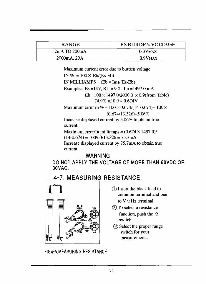
RANGE ES BURDEN VOLTAGE2rnA T0200rnA O.3VMAX
2000rnA,20A 0.9VMAX
Maximum current error due to burden voltage
IN % = 100 x Eb/(Es-Eb)
IN MILLIAMPS = (Eb x Im)/(Es-Eb)
Examples: Es =14V, RL = 9 Q, 1m =1497.0 rnA
Eb =100 x 1497.0/2000.0 x 0.9(from Table)=74.9% of 0.9 = 0.674V
Maximum error in % = 100 x 0.674/(14-0.674)= 100 x(0.674/13.326)=5.06%
Increase displayed current by 5.06% to obtain truecurrent.
Maximum error/In milliamps = (0.674 x 1497.0)/(14-0.674) = 1009.0/13.326 = 75.7rnAIncrease displayed current by 75.7rnA to obtain truecurrent.
WARNINGDO NOT APPLY THE VOLTAGE OF MORE THAN 60VDC OR30VAC.
4-7. MEASURING RESISTANCE.
CD Insert the black lead tocommon terminal and one
to V QHz terminal.
® To select a resistance
function, push the Q
switch.
® Select the proper rangeswitch for yourmeasurements.
FIG4-5.MEASURING RESISTANCE
14

® Touch the probe to the test points, and readdisplay.
*Disregard "-" displayed when the test leads are connectedto the reverse terminals.
Over range is being indicated by flickered figure "0.000".
CAUTIONTURN OFF POWER ON THE TEST CIRCUIT AND DISCHARGEALL CAPACITORS BEFORE ATTEMPTING IN-CIRCUITRESISTANCE MEASUREMENTS. IF AN EXTERNAL VOLTAGEIS PRESENT ACROSS A COMPONENT. IT WILL BEIMPOSSIBLE TO TAKE AN ACCURATE MEASUREMENT OFTHE RESISTANCE OF THAT COMPONENT.
4-8.MEASURING FREQUENCY
FIG 4-6 MEASURING FREQUENCY
CD Insert the black lead tocornmon terminal and red
one to V Q Hz terminal.
® To select a frequencyfunction, push the FREQswitch.
® Select the proper rangeswitch for yourmeasurements.
® Touch the probe to thetest points, and read thedisplay.
The minimum input signal required to trigger is above100mVrms. If the input signal is below the triggerlevel, frequency measurements will not be taken.
15

oZERO AOJ
FIG 4-7. hFE TEST
10
0.0A Mo hFE HOLD
4-9. TRANSISTOR hFE TEST.CD To select a voltagelhFE
function, push the ==VIhFEswitch.
® Select the hFE range Switchfor your measurements.
® Insert the leads(emitter, basecollector) into the properholes of the sochet on thefront panel,according totransistor type NPN or PNP.The display readsapproximate hFE value at thetest condition of Basecurrent 2.4tLA and VCE 3VTo select a hFE function,push the hFE switch on therange switch.
4-10. DIODE TEST
CD Insert the black lead tocommon terminal and redone to V QHz terminal.
® To select diode function,push the ......'l») switch.The forward voltage drop isdisplayed in mV unit.TEST CONDITION:Forward DC current(lmA)When Reversed,"000.0" isflickered.
FIG 4-8. DIODE TEST
16

4-11. CONTINUITY TESTCD Insert the black lead to common terminal and red
one to V Q Hz tenilin
® To select continuity function, to push the
switch.
CAUTIONTURN OFF POWER ON THE TESTCIRCUIT AND DISCHARGE ALLCAPACITORS BEFOREATTEMPTING CONTINUITYTESTING.
Test resistance below 200 Q
mode cause the meter to emit acontinuous tone.
*·4VOHz lOA
~p
~~~'J-c'f.
FIG 4-9. CONTINUITY TEST
4-12. HOLD FUNCTIONA measured value is holded on screen. Push "HOLD" tostop the recording of reading press "HOLD" again tostart it.
~ If you push the "hold" when a measured value is "over range",the display goes out of sight
4-13. HANDLEThehandle can be rotated to four positions. Onepositions. One position allow it to be used as aearring handle.Other positions allow the handle to be used as a bailto tilt the front panel for cor.venient bench topoperation.
17

5.RESOLUTION AND ACCURACY
------ RANGE RESOLUTION ACCURACYI "IJI~1 IIIII~ -- 200mV lOiN
DC 2V 100iN ± (0.05% +4dgt)
VOLTAGE 20V 1IilV200V 10mV
1000V 100mV + (0.15% +4dgt)±(O.5%+2Odgt) . (45Hz - 1KHz)
200mV lOiN± (0.8% + lOdgt) . ( 1KHz- 10KHz)±(l.O%+lOdgt) . (10KHz- 20KHz)±(3.0%+3Odgt). (20KHz- 50KHz)±(O.5%+2Odgt) . ( 45Hz- 1Hz)
2V 100iN ±(O.8%+lOdgt) , (lHz- 10KHz)±(1.0%+2Odgt) ,( lOKHz- 20KHz)
AC +(3.0%+3Odlrt) . ( 20KHz- 50KHz)VOLTAGE ±(0.5%+2Odgt) . (45Hz - 1KHz)
20V 1mV ±(l.5%+2Odgt) . (1KHz - 10KHz)±(2.5%+2Odgt) . ( lOKHz- 20KHz)+(5.0%+2Odgt ) ( 20KHz- 50KHz)
200V 10mV± (0.5% + lOdgt) . (45Hz - 1KHz)+(2.0%+lOdgt) OKHz)
750V 100mV± (1.0% + 2Odgt) . (45Hz - 1KHz)+(3.5%+2Odgt) (lKHz)
2mA O.lmA
DC20mA liLA ±(0.5%+ldgt)
200mA 10 iLACURRENT 2000mA 100 iLA
lOA 1mA + (O.75%+3d,gt)
2mA 0.1 iLA±O.O%+lOdgt) . (45Hz - 10KHz)+(2.0%+2Odgt) . (lOKHz- 20KHz)
20mA liLA ±O.O%+lOdgt). (45Hz - 10KHz)AC -+-:(2.0%+2Odgt) OOKHz- 20KH7)
CURRENT 200mA 10iLA ±O.O%+lOdgt). (45KHz- 10KHz)+ (2.0% + 2Odlrt) (10KHz- 20KHz)
2000mA 100iLA ± 0 .0% + lOdgt). (45Hz - 2KHz)lOA 1mA
200Q O.OlQ + (2.0% + 5dgt)2KQ 0.1 Q
20KQ 1Q ± (0.2% + 2dgt)RESISTANCE 200KQ 10 Q
2000KQ 100 Q ± (0.5% + 2dgt)20MQ 1KQ
FREQUENCY 20KHz 1Hz ± 0.0% + 3dgt)'/1 IKt-I7 'OH?: + (20% + 3dlrt)
hFE BASE CURRENT: 3.5I£A. VCE: 4.5V APPROXDIODE TEST VOLTAGE: 4.5V APPROX. MAXIMUM TEST CURRENT: lmA
CONTINUITY THRESHOLD: 200 Q OR LESS• Temperature coefficient: 0.15 X (spec.acc'y)/ t. (18 t or ) 28 t• Accuracy is ginven as ±(% ofreading + number of least sgnificant digits) at 18 t to 28 t with relative humidityup to 80% for a period ofone year after calibraton.
* Sources like small hand-held radio transceivers. fixed station radio and television transmitters, vehicle radiotransmitters and cellular phones generate electromagnetic radiation thaI may induce voltages in the festleads of the multimeter. Tn such cases the accuracy of the multimeter cannot be guaranteed due to physical reasons.
18

6.MAINTENANCE
WARNINGTO AVOID ELECTRICAL SHOCK OR DAMAGE TO THE METER,DO NOT GET WATER INSIDE THE CASE. REMOVE THE TESTLEADS AND POWER CORDS ANY INPUT SIGNALS BEFOREOPENING THE CASE.
6-1.INTRODUCTIONThis section contains the maintenance information foryour digital multimeter. This information isdivided into service information, calibration, fusefuse replacement, etc.
6-2. FUSE REPLACEMENTAfter disconnecting test leads and power cords turning off themultimeter, remove old fuse located with rear panelreplace with new fuse. See FIG 4-1.
7. ACCESSORIES
Test leads : 1setPower cord : 1pcOperating manual : 1copyFuse: Ipc
19

8. MEMO
20

TENIIA@TEST EQUIPMENT
405 Pioneer Blvd._________ Springboro, ohio 45066 _