
TENNET, NL OFFSHORE WIND FARM TRANSMISSION SYSTEMS · PDF fileTENNET, NL OFFSHORE WIND FARM...
38
TENNET, NL OFFSHORE WIND FARM TRANSMISSION SYSTEMS 66 kV Systems for Offshore Wind Farms TenneT Report No.: 113799-UKBR-R02, Rev. 2 Document No.: 74107077-1 Date: 2015-03-05
Transcript of TENNET, NL OFFSHORE WIND FARM TRANSMISSION SYSTEMS · PDF fileTENNET, NL OFFSHORE WIND FARM...

TENNET, NL OFFSHORE WIND FARM TRANSMISSION SYSTEMS
66 kV Systems for Offshore Wind Farms TenneT
Report No.: 113799-UKBR-R02, Rev. 2
Document No.: 74107077-1
Date: 2015-03-05

DNV GL – Report No. 113799-UKBR-R02, Rev. 2 – www.dnvgl.com Page i
Project name: Tennet, NL Offshore Wind Farm Transmission
Systems
DNV GL Energy
PO Box 9035
6800 ET Arnhem
The Netherlands
Tel: +31 26 356 9111
Report title: 66 kV Systems for Offshore Wind Farms
Customer: TenneT
Contact person: Frank Wester
Date of issue: 2015-03-05
Project No.: 74107077
Organisation unit: RA NL
Report No.: 113799-UKBR-R02, Rev. 2
Document No.: 74107077-1
Applicable contract(s) governing the provision of this Report:
Objective:
Prepared by: Verified by: Approved by:
Tino Schlemmer
Lyndon Greedy
Peter Vaessen
Peter Kolmeijer
Hans Cleijne
[Name]
[title]
[Name]
[title]
[Name]
[title]
[Name]
[title]
Copyright © DNV GL 2014. All rights reserved. This publication or parts thereof may not be copied, reproduced or transmitted in any
form, or by any means, whether digitally or otherwise without the prior written consent of DNV GL. DNV GL and the Horizon Graphic
are trademarks of DNV GL AS. The content of this publication shall be kept confidential by the customer, unless otherwise agreed in
writing. Reference to part of this publication which may lead to misinterpretation is prohibited.
DNV GL Distribution: Keywords:
☐ Unrestricted distribution (internal and external) Offshore wind, 33/66kV, Grid connection, Borssele
☐ Unrestricted distribution within DNV GL
☐ Limited distribution within DNV GL after 3 years
☐ No distribution (confidential)
☐ Secret
Rev. No. Date Reason for Issue Prepared by Verified by Approved by
0 2015-01-16 First Draft version Tino Schlemmer,
Lyndon Greedy
Peter Vaessen Hans Cleijne
1 2015-02-24 Update based on stakeholder input Tino Schlemmer,
Lyndon Greedy
Hans Cleijne
2 2015-03-05 Final version based on TenneT review
Updated layout, electric losses
Tino Schlemmer,
Lyndon Greedy
Peter Vaessen Hans Cleijne

DNV GL – Report No. 113799-UKBR-R02, Rev. 2 – www.dnvgl.com Page ii
Table of contents
1 EXECUTIVE SUMMARY ..................................................................................................... 2
2 INTRODUCTION .............................................................................................................. 5
3 66 KV SYSTEMS OVERVIEW ............................................................................................. 7
4 EXAMPLE: BORSSELE OFFSHORE WIND FARM .................................................................. 10
5 WIND TURBINE SYSTEMS .............................................................................................. 15
5.1 Transformer 15
5.2 Tower Cabling 16
5.3 Switchgear 17
5.4 Through-life issues 19
5.5 Availability impact on supply chain 20
5.6 Wind turbine certification 20
5.7 Wind turbine availability 20
6 ARRAY CABLING ........................................................................................................... 22
6.1 Procurement 22
6.2 Cable construction 23
6.3 Installation 25
6.4 Through-life issues 25
6.5 Availability impact on supply chain 25
7 OFFSHORE SUBSTATION SYSTEMS ................................................................................. 27
7.1 Electrical systems arrangement 27
7.2 Switchgear 27
7.3 Reactive compensation 30
7.4 Other affected systems 30
7.5 Through-life issues 30
8 COSTS OF COMPONENTS ............................................................................................... 31
9 CONCLUSIONS ............................................................................................................. 32

DNV GL – Report No. 113799-UKBR-R02, Rev. 2 – www.dnvgl.com Page 1

DNV GL – Report No. 113799-UKBR-R02, Rev. 2 – www.dnvgl.com Page 2
1 EXECUTIVE SUMMARY
In order to increase the Dutch offshore wind capacity up to 4,450 MW until 2023 the Dutch Government
agreed to develop three new wind-park zones in the North Sea which are Borssele, Hollandse Kust Zuid
and Hollandse Kust Noord with a total capacity of approximately 3,500 MW.
The current standard voltage level for offshore wind park inter-array grids is commonly 33 kV. Due to
the fact that the average single capacity of wind turbines is going to increase to 6-8 MW and higher and
the average total capacity of wind parks for new offshore wind projects also increases, a higher voltage
level of 66 kV is expected to be used for inter-array connections of new offshore wind projects.
TenneT is considering the option of utilising 66 kV as an array system voltage. Although they shall not
provide the array cabling, they would need to accommodate a 66kV system voltage within the offshore
substation electrical system design. It is their intention to discuss this potential 66 kV solution with
offshore wind farm developers as a real opportunity to contribute to this innovative new technology. In
consideration of envisaged wind turbine and wind park installed capacities for each parcel of the new
Dutch wind park zones the utilisation of 66 kV is a practical electrical system design option for the inter-
array cable network.
The intention of this whitepaper document is to provide a discussion on the current situation of the 66 kV
inter-array solution and identify the pros and cons of this new technology against the usual common
practice of the 33 kV voltage level in consideration of the special conditions of the new Dutch wind park
zones, particularly with regards to Borssele.
Therefore a review on the following issues was made:
Type of technology for 66 kV inter-array grid connections
Availability of components
Market conditions (number of suppliers and market power)
Need for testing and certification of electrical components
Time line
Cost of the components and of the grid connection
Necessity for recertification of wind turbines when applying 66-kV-technology.
Potential impacts on wind turbine electrical system design and certification
Impact on wind farm design
Impact on installation
As offshore wind turbines and wind farms become larger it is prudent for electrical system designs to
consider the connection and collection systems in such a way that they are optimised to be suitable for
the elevated output power of the wind turbines as well as the large geographical areas over which they
operate. This need to optimise electrical system designs with a view to reducing costs, leads electrical
engineers to review electrical infrastructure options.
Typically offshore wind farm projects utilise array cables operated at 33 kV to collect the output of the
wind turbines and route it to a central substation location where the voltage can be stepped up for the
efficient onward transmission of power to the land based transmission system. The offshore wind energy
industry in general has, for some time, considered the potential for increasing the array system voltage

DNV GL – Report No. 113799-UKBR-R02, Rev. 2 – www.dnvgl.com Page 3
from 33 kV to a higher voltage. Various standardised voltage levels above 33 kV can be considered
including 48 kV, 56 kV, 66 kV and 72 kV. Much industry focus has been on the use of 66 kV as an
operating voltage. By transferring to a higher voltage, the relative current levels reduce for a given
power level. And, where the current reduces, the potential is opened up to transport greater power along
the same cross sectional area cable. The notable benefits in transferring to a higher voltage are that,
when compared with the 33 kV voltage, less array cabling would be required and this can result in
substantial capital costs savings, in terms of both cable purchase and installation.
The prospect of shifting from 33 kV to 66 kV and the potential benefits it brings makes good sense
although the transfer does not come without issues. This document covers the electrical system from the
top of the wind turbine where electrical power is produced, through the wind turbine, the array cabling
and finally at the substation where the interface with the offshore substation transformer is located.
Borssele offshore wind farm (1,400 MW) located off the coast of the Netherlands was selected as an
example to make a comparison between 66 kV and 33 kV as an array system voltage. A comparison
between the two design options showed that approximately one third of cable length (135 km), worth 50
million euro can be saved when switching to 66 kV inner-array cables.
Wind Turbines: Within the wind turbine itself the key areas requiring consideration are the wind turbine
transformer as, rather that stepping the voltage up to 33 kV the voltage is stepped up to 66 kV. The
consequential effect of this is that a higher winding ratio transformer, higher voltage cabling and higher
voltage switchgear would be required. The higher ratio transformer is likely to be of the same mass as
its 33 kV counterpart and although the dimensions of which are expected to increase they are only
expected to increase marginally. Within the context of the nacelle or tower dimensions, this is not
considered to be a significant or obstructive issue. Flexible 66 kV tower cabling has a marginally
increased bending radius and is considered to be a generally standard product offering so no significant
issues are expected here. The 66 kV switchgear which forms the interface between the wind turbine
electrical system and the subsea array cable network, although a standard product offering within the
electrical power industry, is not a tailor made solution for wind turbine technology. That said, key
manufacturers are able to offer a solution. Some manufacturers are going through the process of
establishing designs specifically targeted at the offshore wind market. An issue could arise because the
designs are based on SF6-GIS, which may be banned in the future. It is expected that these new
solutions will be competitively priced. In general and with reference to 66kV systems, it is the
expectation of DNV GL that there will be no obstructive certification issues with respect to the main
electrical systems within the wind turbine.
Subsea Array Cabling: Common subsea cable technology for offshore wind farm applications is often
described as wet-design. It does not include a lead sheath which makes it both relatively straightforward
to install, as it is flexible, and of a lower unit cost than cable which includes a lead sheath. This means
that the installation of subsea cable with a lead sheath would be both fairly cumbersome to install and
possibly more expensive per meter cable than the 33 kV option. Key high profile cable manufacturers are
understood to be developing wet-design products and addressing the process of certification. This
process is also understood to vary from manufacturer to manufacturer although generally is expected to
be complete within a period of up to 18 months.
Offshore substation: Within the offshore substation topside platform, the key areas affected by the
transition from 33 kV to 66 kV are the array system switchgear bays and the reactive power
compensation equipment. The switchgear bays are not considered to be a significant issue as this
equipment is available and has been available for many years. As such much experience in terms of

DNV GL – Report No. 113799-UKBR-R02, Rev. 2 – www.dnvgl.com Page 4
operation, maintenance and reliability has been accumulated. With regards to the compensation
equipment, there will be a requirement for equipment with elevated ratings. The reason for this is driven
by the 66 kV array cabling. By increasing the array system voltage there is a consequential increase in
the reactive power flows within the array cable network. Excess levels of reactive power both remove the
power transfer capability of the cable and bring about additional electrical losses. A means of addressing
this issue is by means of reactive power compensation equipment installed within the offshore substation.
If the reactive compensation is connected directly at 66 kV there will be an increase in dimensions due to
the increase in insulation requirements. A further increase in dimensions will come about because of the
elevated ratings of such reactive compensation. These issues are addressed through common electrical
engineering design and so the significant implication in changing from 33 kV to 66 kV with respect to
reactive compensation is a rise in cost. There is an increase in costs associated with the enhanced
reactive power compensation equipment, ballpark estimates for reactive power compensation would
suggest somewhere in the region of 50% over the 33 kV counterpart.
Based on information coming from well-known cable manufacturers prices for 66-kV wet type cables
would be between 10 and 20% higher than for 33-kV-cables of same type and diameter, which is more
than outweighed by doubling the transfer capacity and the additional fact, that the total cable length will
be lower for 66-kV-solution.
66kV/LV wind turbine transformers are about 40-50% more expensive than 33kV/LV-transformers of
same power capacity. 66-kV switchgear is currently significantly more expensive than 33-kV switchgear
to be used in wind turbines, (indicative figures would suggest an increase of around 40 %), but further
development of appropriate 66-kV switchgear for wind turbines could lead to significant price reduction
within the next few years.
In total a CAPEX reduction of up to 15% can be achieved when using a 66-kV-inter array solution
compared to a 33-kV usual basic design a 350 MW wind farm using a radial layout.
Common practice in developing any large electrical installation is to conduct electrical concept studies
during the early stages of project development, including a risk assessment of the components. By
undertaking such studies the benefits and drawbacks can be quantified clearly. Such studies are outside
the scope of this document although such studies are expected to clarify the decision with confidence,
the use or not of 66 kV as an array system voltage.

DNV GL – Report No. 113799-UKBR-R02, Rev. 2 – www.dnvgl.com Page 5
2 INTRODUCTION
In order to increase the Dutch offshore wind capacity up to 4,450 MW until 2023 the Dutch Government
agreed to develop three new wind-park zones in the North Sea which are Borssele, Hollandse Kust Zuid
and Hollandse Kust Noord with a total capacity of approximately 3,500 MW.
TenneT as the Dutch TSO is responsible for the connection of the wind parks to the Dutch transmission
grid. Therefore it is planned to install two offshore substation platforms inside the zone where substation
Alpha shall be located in the upper left corner of parcel II and substation Borssele Beta in the upper left
corner of parcel III.
The current standard voltage level for offshore wind park inter-array grids is commonly 33 kV. Due to
the fact that the average single capacity of wind turbines is going to increase to 6-8 MW and higher and
the average total capacity of wind parks for new offshore wind projects also increases, a higher voltage
level of 66 kV is expected to be used for inter-array connections of new offshore wind projects.
TenneT is considering the option of utilising 66 kV as an array system voltage. Although they shall not
provide the array cabling, they would need to accommodate a 66kV system voltage within the offshore
substation electrical system design. It is their intention to discuss this potential 66 kV solution with
offshore wind farm developers as a real opportunity to contribute to this innovative new technology. In
consideration of envisaged wind turbine and wind park installed capacities for each parcel of the new
Dutch wind park zones the utilisation of 66 kV is a practical electrical system design option for the inter-
array cable network.
The intention of this whitepaper document is to provide a discussion on the current situation of the 66 kV
inter-array solution and identify the pros and cons of this new technology against the usual common
practice of the 33 kV voltage level in consideration of the special conditions of the new Dutch wind park
zones, particularly with regards to Borssele.
Therefore the following chapters of the document provide a review on the following issues:
Type of technology for 66 kV inter-array grid connections
Availability of components
Market conditions (number of suppliers and market power)
Need for testing and certification of electrical components
Time line
Cost of the components and of the grid connection
Necessity for recertification of wind turbines when applying 66-kV-technology.
Potential impacts on wind turbine electrical system design and certification
Impact on wind farm design
Impact on installation

DNV GL – Report No. 113799-UKBR-R02, Rev. 2 – www.dnvgl.com Page 6
Considering:
General configuration and wind park design options
Wind park main electrical components
o Transformer
o Switchgear
o Cabling
Offshore substation systems
o Transformer
o Switchgear
o Reactive power compensation
Through life issues
o Reliability
o Operation and Maintenance
o Grid losses

DNV GL – Report No. 113799-UKBR-R02, Rev. 2 – www.dnvgl.com Page 7
3 66 KV SYSTEMS OVERVIEW
Wind turbines are becoming larger, not only in terms of physical dimensions but, in the context of this
document, installed capacity.
In the early 1990s the typical rating of a wind turbine was around 300 kW. Manufacturers were able to
learn and enhance the capabilities of their products such that by the year 2000 a 1500 kW machine was
becoming something of a standard product offering. This trend in rising wind turbine ratings has
continued such that at the present time an 8 MW machine is available for purchase. Furthermore, it is
understood that designers are considering or actively working on designs with installed capacities at or in
excess of 10 MW.
In the design of most if not all electrical installations it is wise to consider the issue of costs and
efficiency. Early wind turbines with ratings of a few hundred kilowatts typically had terminal voltages of
400 V and array cable systems were, in many cases, operated at voltages up to around 11 kV. With the
growth in both wind turbine ratings and wind farm installed capacities, turbine terminal voltages have
increased to either 690 V, 1,000 V or in some cases 3,300 V with array cable voltages operated at up to
33 kV.
New large offshore wind farms include a combination of substantial installed capacity, coverage over a
large geographical area and large wind turbines. It is the combination of these issues which strongly
indicate a requirement to carefully consider the basic electrical system design, rather than simply
drawing upon the experience of what are considered to be, established electrical collection arrangements.
A key area for conceptual design consideration is the operating voltage of the array cable system. For a
given power cable, by increasing the voltage, from for example 33 kV to 66 kV, elevated levels of power
can be transported; possibly up to twice as much in this example. This point is demonstrated in
Figure 3-1.
Figure 3-1: Comparison of 33 kV and 66 kV cable capacity
With an array system voltage operating at 33 kV, around 40 MW of power is transportable using a
630 mm2 copper conductor cable. However, the same cable cross-section is able to transport around
80 MW when operating the array system voltage at 66 kV. This means that rather than having two array
circuits, just one would be required in the 66 kV case to transport the same level of power.
DNV GL © 20141
7MW
7MW
33kV
66kV
Case 1: 33kV, 3-Core, 630mm2 copper
conductor cable
Case 2: 66kV, 3-Core, 630mm2 copper
conductor cable

DNV GL – Report No. 113799-UKBR-R02, Rev. 2 – www.dnvgl.com Page 8
The notable benefit in using one circuit over two to transport the same level of power is that for a given
quantity of turbines, a smaller quantity of cabling may be required for the 66kV option, but that strongly
depends on the wind farm’s turbine layout. In the example shown in Figure 3-1 there is the potential to
remove one-third of the quantity of the array cable, when compared with the 33 kV case – however, this
is the ideal case. And where the quantity of cable reduces, there is the potential for reduction in capital
costs over the 33 kV option.
Table 3-1: Benefits and Drawbacks of 66kV cabling
Area Issue Benefits Drawbacks
Cable supply Reduction in
quantity
Up to a third the quantity of
cable when compared with the
33 kV option.
Increase in unit cost (€/m) of
cable
Cable
installation
Reduction lay
operations
Reduced installation time Enhanced, more costly cable
installation tooling
requirements
Cable
congestion
Lower risk of damage to other
cables around substation during
cable laying
Cable
congestion
Reduced thermal interaction of
cabling around substation
foundation and within
substation J-Tubes
Cable operation
Electrical losses May be reduced, especially
when not utilizing the double
transmission capability
Reactive
compensation
of charging
power
Four times higher charging
power leads to increased
weight and costs for
compensation equipment
Outage of compensation
equipment might lead to
(partial) wind farm outage
Offshore wind farm projects, in excess of ~500 MW cover relatively large geographical areas. With
operating voltages of 33 kV and with a basic design requirement to avoid cable congestion on the seabed
around the offshore substation it can be an appropriate electrical system design choice to install more
than one offshore substation.
The example of Borssele offshore wind farm provided in Section 4 of this report demonstrates the point
with regards to potential cable congestion, with substation A (East) accommodating 10
incoming/outgoing array cable circuits in the 66 kV case and 23 in the 33 kV array cable case. 23 array
cables entering one location can make for a challenging installation process and secondary structural
system design.

DNV GL – Report No. 113799-UKBR-R02, Rev. 2 – www.dnvgl.com Page 9
As it is possible to accommodate more power on a 66 kV circuit and thus minimise the quantity of array
circuits emanating the substation, there is at least, the possibility that fewer offshore substations could
be required in the 66 kV case. The structural, electrical and installation costs associated with a single
offshore substation are significant. Therefore by reducing the number of offshore substations, there is
the potential to reduce the capital costs of an offshore wind farm installation.
By changing from 33 kV to 66 kV a number of areas within the electrical system will be affected and will
therefore require electrical system design consideration. In addition to the array cable network, notable
areas include the main electrical systems within each wind turbine and the switchgear and compensation
systems within the offshore substation(s).
Typically within a wind turbine system the power is produced at low voltage and then stepped up to
match that of the external system (e.g. 33 kV or 66 kV). The key issues therefore within the wind
turbine electrical system are the ratio of the power transformer, the tower cabling and the wind turbine
primary switchgear. Rather than operation at a voltage of 33 kV these items of equipment need to be
suitable for operation at 66 kV. Electrical products are readily available for these areas. They do however
come with a price increase over the 33 kV option. Indicative figures would suggest an increase of around
40 %.
With regards to the substation electrical system affected by the change from 33 kV to 66 kV there is the
switchgear itself. However much like the wind turbine switchgear, electrical products suitable for
operation at 66 kV are readily available within the market place and similarly come with an elevated cost
over the 33 kV option. Another issue that will be affected by a change from 33 kV to 66 kV as an
operating voltage is an increased requirement for reactive power compensation. This is required to
compensate an elevated reactive power effect within the array cabling system when operating it at a
higher voltage. This is necessary to ensure that the full capability of the cabling is available and that the
electricity is transported efficiently. There is an increase in costs associated with the enhanced reactive
power compensation equipment, ballpark estimates would suggest somewhere in the region of 50% over
the 33 kV counterpart.
In order to quantify the reactive power issue clearly, a design of the optimised array cable system would
be required and load flow modelling would normally be undertaken. Detailed modelling of such nature is
outside the scope of this work/report.
Further detailed assessment of the issues involved in transferring from 33kV to 66kV as an array system
voltage, are discussed in the following sections of this report.

DNV GL – Report No. 113799-UKBR-R02, Rev. 2 – www.dnvgl.com Page 10
4 EXAMPLE: BORSSELE OFFSHORE WIND FARM
Borssele offshore wind farm located off the coast of the Netherlands has been selected as an example to
make a comparison between 66 kV and 33 kV as an array system voltage. In the example DNV GL has
used, it is proposed that there are two substations collecting the output of 234 x 6MW wind turbines.
In both the 33 kV and 66 kV cases, DNV GL has limited the number of cable sizes to two as this is typical
within offshore wind farm developments. 630mm2 and 240mm2 copper conductor cables for the 66kV
case have been assumed. 800mm2 and 240mm2 copper conductor cables for the 33kV case have been
assumed
Using preliminary data provided by cable manufacturers, it is calculated that the 66kV, 630mm2 cable is
able to carry, at most, 83.8 MVA and the 240mm2 cable is cable to carry, at most, 51.2 MVA. Assuming
the wind turbines may be called upon to operate over a power factor of 0.95 importing and exporting,
each cable is, respectively, able to carry the output of 13 and eight wind turbines.
Using these two cable sizes the following array cable layout has been developed.
Figure 4-1: 66kV Array cable layout arrangement
Using preliminary data provided by cable manufacturers, it is calculated that the 33kV, 800mm2 cable is
able to carry, at most, 39 MVA and the 240mm2 cable is able to carry, at most, 22 MVA. Assuming the
wind turbines may be called upon to operate over a power factor range of 0.95 importing and exporting,
each cable is, respectively, able to carry the output of six and three wind turbines.
Using these two cable sizes the following array cable layout has been developed.

DNV GL – Report No. 113799-UKBR-R02, Rev. 2 – www.dnvgl.com Page 11
Figure 4-2: 33kV Array cable arrangement
It is to be noted that the layouts are not necessarily optimised and furthermore have not been assessed
through load flow study work in terms of voltage rise/drop.
The quantities of cable have been summated and are provided in the table below.
Cable length in
m
Layout System Voltage:
66 kV 33 kV
Substation 630mm2 240mm2 800mm2 240mm2
A (West) 63,710 98,840 173,280 61,090
B (East) 61,290 89,430 142,560 60,910
Totals: 124,990 185,730 315,840 122,000
Table 4-1: 66kV and 33kV array cable lengths
Assigning costs is not a straight-forward process as it will be dependent upon the market conditions.
DNV GL has therefore assigned costs on a unit basis with a possible range, as follows.
Costs per metre in Euro
System Voltage:
66 kV 33 kV
630mm2 240mm2 800mm2 240mm2
Low 386 182 420 165
Medium 425 200 465 180
High 468 220 515 200
Table 4-2: 66kV and 33kV array cable costs
Using the above array cable quantities and costing figures, the following totals shown in the possible
costs if the medium cost values in Table 4-2 are assumed.

DNV GL – Report No. 113799-UKBR-R02, Rev. 2 – www.dnvgl.com Page 12
Costs in Euro Layout System Voltage:
66 kV 33 kV
Substation 630mm2 240mm2 800mm2 240mm2
A (West) 27M 20M 81M 11M
B (East) 26M 18M 66M 11M
53M 38M 147M 22M
Totals: 91M 169M
Table 4-3: 66kV and 33kV array cable cost totals
Caution should be exercised in the interpretation and use of these cost figures. DNV GL has based this
assessment on a unit cost of cabling. The Borssele example here represents a substantial quantity of
cable and therefore the medium unit cost could be lower than that provided in the table. What is also to
be made clear is that, as there is not yet a 66 kV wind farm subsea array cable market in place, there is
some uncertainty in the costs provided for the 66kV case. Therefore all figures should be treated with
some degree of caution and considered to be, indicative.
A chart showing the low, medium and high cost estimates for the array cable costing is provided in
Figure 4-3 below.
Figure 4-3: Comparison of 66kV and 33kV array arrangements for Borssele
A number of other issues which emphasise the differences between the use of 33kV and 66kV as an
array system voltage are:
Installation: With a lower quantity of cable to install, there is expected to be a lower installation cost for
the wind farm. Assigning any figure to cable installation can be a challenging process and dependent
upon market conditions, vessel availability and perhaps most notably, seabed conditions. Differences in
offers for array cable installation can, in some cases, be as much as 100%. As a very ball-park guidance,
installation costs as a unit basis could be around €200 to greater than €400 per metre.
Losses – it is expected that the losses associated with the 66kV system when compared with the 33kV
system will be less. This is a significant point as losses can be capitalised in monetary terms. Over the
lifetime of a project, this monetary value can be significant.

DNV GL – Report No. 113799-UKBR-R02, Rev. 2 – www.dnvgl.com Page 13
By way of example DNV GL has reviewed the annual production losses associated with the connection of
the 12 wind turbines in far western area of site IV of the Borssele wind farm zone. In the 66kV case, the
12 turbines are connected by means of one 66kV substation feeder circuit using 630mm2 and 240mm2
cables. In the 33kV case the connection of 12 turbines requires two 33kV substation feeder circuits using
800mm2 and 240mm2 cables
The annual production losses for the 66kV case and applicable only to the 66kV cabling (not the wind
turbine transformers) are 0.55%. The annual production losses for the 33kV case and applicable only to
the 33kV cabling (not the wind turbine transformers) are 0.80%.
Substation cables – In the 66kV example there are 11 array cables entering substation A (West) and 10
array cables entering substation B(East). In the 33kV example there are 22 array cables entering
substation A and 21 array cables entering substation B.
It is often preferable to route all array cables along one side elevation of the offshore substation. It is
noted that 22 array cables is considered to be a large number, possibly excessive. With this number of
cables and associated J-Tubes routed up the side elevation of the substation this could turn into an
unmanageable situation.
An array cable design around the offshore substation is necessary which addresses, amongst other
issues, the requirements for cable installation, diver intervention, vessel-access during wind farm
operations as well as cable design, heating and de-rating factors.

DNV GL – Report No. 113799-UKBR-R02, Rev. 2 – www.dnvgl.com Page 14

DNV GL – Report No. 113799-UKBR-R02, Rev. 2 – www.dnvgl.com Page 15
5 WIND TURBINE SYSTEMS
5.1 Transformer
Considering wind turbine capacities of 6 MW to 8 MW, step-up transformers with 66 kV as primary
voltage and a rated apparent power rating of 6-10 MVA will be required. This type of transformer is a
well proven technology and can be offered by a significant number of well-known international
manufacturers. A potentially challenging area is the offshore installation of such transformers in wind
turbine towers. Therefore issues like environmental conditions (humidity, salinity), dimensions and
weights, insulation type, vibration and logistics become more prominent. Transformers can be installed
either in nacelle, the transition piece or the turbine tower. Some turbines have been erected with the
transformer installed within an external container to protect the transformer against environmental
influences. Due to limited space inside and limited door dimensions as well as weight limitations, slim
transformers are an option.
The optimum solution is the installation of the transformer in the nacelle close to the generator. In the
nacelle the transformers may be stressed by low frequency vibrations between 5 and 250 Hz coming
from wind and wave loading acting upon the wind turbine structure. Both liquid-filled and dry type
transformers are sensitive to these vibrations. Dry-type transformers are more sensitive to condensation,
electrical creep, partial discharges, cracks, temperature variations and contamination than oil filled
transformers. These issues are assessed during testing.
Dry-type 66 kV/LV transformers are generally available used for other purposes, but weights and
especially dimensions of such transformers raise issues when installed within the nacelle or the turbine
towers. Transformer manufacturers provide slim transformer designs to address the issue.
Liquid-filled transformers with their steel tank having a surface treatment which can go as high as
C5I+M, surpassing the highest ISO 12944-2 [3] classes, are generally resilient to this corrosive
environment. Furthermore the oil handling requires management for transformer installation in the
nacelle. It is preferable for liquid-filled transformers to be installed in the tower.
Along with increasing transformer voltage level, weight and dimensions of the transformers increase due
to the larger electrical design clearances and volumes of insulation material necessary. Comparing
33 kV/LV and 66 kV/LV transformers of same transformation capacities it can be roughly stated that
66 kV/LV transformers have a lighter and narrower winding design due to lower current flow on HV-side.
On the other hand the total dimensions of 66kV/LV transformers are bigger due to higher creepage
distances and significantly higher masses and dimensions.
A possible alternative is the utilisation of what are referred to as Bio-Slim transformers which use bio-
degradable ester as the insulation material. Such transformers are offered for voltage levels up to
72.5 kV on the HV-side and an apparent power rating at the present time of up to 7 MVA. These
transformers fulfil applicable IEC as well as ANSI-standards. Well-known transformer manufacturers are
developing such transformer designs.
In consideration of space limitations inside the nacelle and tower of turbines, forced cooled KFAF
transformers are preferable to ensure that the transformer is as slim as possible. The dimensions of a
forced cooled Bio-Slim transformer rated at 6 MVA, suitable for a 5 MW wind turbine are
2,650 x 1,170 x 2,660 mm (h/w/l) which would fit through door entrances to enable installation inside
the turbine tower.

DNV GL – Report No. 113799-UKBR-R02, Rev. 2 – www.dnvgl.com Page 16
With regards to market availability liquid-filled 66 kV transformers are generally available as required.
However certification for offshore utilisation requires finalising. Due to space limitations for nacelle or
tower installation, dry-type transformers are under development. The number of suppliers at the present
time supplying transformers suitable to fit in the nacelle or tower is limited, but due to ongoing
manufacturer’s development the number of such available transformer types and suppliers will increase
very fast in accordance with market demand.
Prior to implementation and the commencement of new Dutch offshore projects a higher number of
suitable transformers from different manufacturers should be available inclusive of dry-type transformers.
New dry-type transformers designs from several manufacturers meeting requirements for turbine tower
installations should be commercially available within the next 2-3 years, early enough to, be used for
Borssele-Project. However, no record of performance (many years of successful operation will be
available).
5.2 Tower Cabling
The issue of the flexible cables routed down the wind turbine tower will depend upon the wind turbine
electrical arrangement, more specifically where the wind turbine transformer is located within the
structure. Some wind turbine manufacturers install the transformer within the nacelle, and some in the
tower. These two configurations are shown in Figure 4-1.
Figure 5-1: Wind turbine cabling and transformer location
Where the transformer is located in the base of the tower, as in arrangement 1 in Figure 4-1 the flexible
tower cables remain unchanged if going from 33 kV to 66 kV. However in the case of arrangement 2
where the transformer is located in the nacelle, the tower cables will be operated at 66 kV and as such
will require flexible cabling suitable for operation at 66 kV. With the increase in voltage however and
given the same installed capacity (real power output), there will be a reduction in current and as such a
reduction in the current rating and hence cross sectional area of the cables required.
DNV GL © 20141
Generator
Power Converter
Power transformer
Switchgear
Generator
Power Converter
Power transformer
Switchgear
Arrangement 1 Arrangement 2
DNV GL – Report No. 113799-UKBR-R02, Rev. 2 – www.dnvgl.com Page 17
The added insulation requirements for 66 kV flexible cables will incur a higher bending radius than the
33 kV cabling equivalent. However, this is not viewed as a major issue as 66 kV flexible cables are
available within the marketplace and with regards to installation and operation, have a marginally
greater bending radius. An increase in cable cost per meter will be applicable however; it is expected to
be around 10%.
5.3 Switchgear
An increase of the inter-array voltage from 33 kV to 66 kV necessitates a step from medium voltage to
high voltage. Along with this step, some requirements and construction principles for switchgear change
even for small current ratings of 1 kA as needed.
Currently there is a limited level of applicable specific standards for offshore wind turbine utilisation of
HV switchgear in consideration of the shocks and accelerations as well as the environmental conditions
the equipment is required to resist.
Well known switchgear manufacturers supply standard switchgear available for rated voltages of 72.5 kV.
However the dimensions of such switchgear types and configurations tend to be excessive and not
generally lend themselves to installation inside the turbine tower. Air insulated switchgear (AIS)
solutions for 72.5 kV are similarly excessive for such installations. SF6 insulated switchgear (GIS) is
significantly smaller but more costly than air insulated versions. Nevertheless all well-known
manufacturers are developing new switchgear solutions adapted to the special requirements to be used
in offshore wind farms. Some of such solutions are already commercially available while others are very
close to commercial availability. In the future SF6 might be banned requiring other solutions for instance
based on vacuum technology.
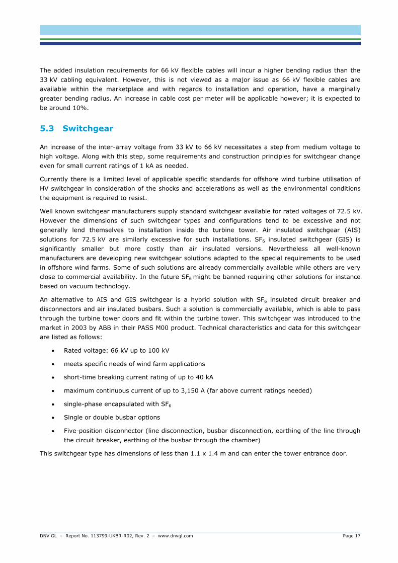
An alternative to AIS and GIS switchgear is a hybrid solution with SF6 insulated circuit breaker and
disconnectors and air insulated busbars. Such a solution is commercially available, which is able to pass
through the turbine tower doors and fit within the turbine tower. This switchgear was introduced to the
market in 2003 by ABB in their PASS M00 product. Technical characteristics and data for this switchgear
are listed as follows:
Rated voltage: 66 kV up to 100 kV
meets specific needs of wind farm applications
short-time breaking current rating of up to 40 kA
maximum continuous current of up to 3,150 A (far above current ratings needed)
single-phase encapsulated with SF6
Single or double busbar options
Five-position disconnector (line disconnection, busbar disconnection, earthing of the line through
the circuit breaker, earthing of the busbar through the chamber)
This switchgear type has dimensions of less than 1.1 x 1.4 m and can enter the tower entrance door.

DNV GL – Report No. 113799-UKBR-R02, Rev. 2 – www.dnvgl.com Page 18
Figure 5-2: Gas-insulated switchgear PASS M00 72.5kV Wind made by ABB
Schneider Electric is planning on introducing a similar GIS solution specifically for wind turbine
applications (Figure 5-3) with the following technical characteristics and data:
Rated voltage: 72.5 kV
meets specific requirements of wind farm applications
short-time withstand current of up to 25 kA (3s)
maximum continuous current of up to 2,500 A
single-phase encapsulated with SF6
dimension (one bay, 1,250 A) (0.6 x 1.75 x 2.96)m (width x depth x height)
dimension (one bay, 2,500 A) (1.2 x 1.75 x 2.96)m (width x depth x height)
Figure 5-3: Gas-insulated switchgear 72.5kV made by Schneider Electric

DNV GL – Report No. 113799-UKBR-R02, Rev. 2 – www.dnvgl.com Page 19
Other leading switchgear manufacturers like Siemens and Alstom have standard SF6 insulated switchgear
available for rated voltages of up to 72.5 kV. This switchgear is understood to be suitable for installation
within the transition piece of offshore wind turbine structures. This switchgear can accommodate single,
double or triple cable system connections.
Alstom for instance offers a complete 66 kV solution within their Haliade 150, 6 MW wind turbine. Alstom
also announced a new SF6-free switchgear offering suitable for 66 kV offshore installation using a newly
developed insulation gas mixture referred to as g3 (green gas for grid) which is understood to be made
available very soon.
An installation of 66 kV switchgear in a separate compartment placed underneath the nacelle or mounted
in a lower location outside the tower is generally possible as an alternative option. The drawbacks
however are that added costs are incurred due to the accommodation requirements of the switchgear
the added structural support.
5.4 Through-life issues
Operations and maintenance.
The operation & maintenance efforts for switchgear components are generally low and can be assessed
to be approximately equal between 33 kV and 66 kV switchgear. According to information from
manufacturers, primary switchgear components are having relatively low maintenance requirements. E.g.
continuous protection testing is to be undertaken on secondary systems, which is considered to be
independent the voltage level.
Operation and maintenance activities necessary for the transformer depend on the general type of
transformers used. For dry-type transformers these efforts are limited and normally only visual
inspections and checking of winding temperature controls would be necessary. Due to the offshore
ambient conditions and vibration issues, cleaning of windings and tightening of mechanical parts might
be necessary in exceptional cases.
If oil or other liquid filled transformers are used the operation and maintenance efforts needed are higher.
Oil or liquid analyses need to be undertaken continuously to ensure ongoing and safe operation of the
transformers. Another issue is corrosion protection of steel tanks and transformer cooling systems due to
harsh environmental conditions of the marine air, which is very humid, very salty and can be highly
variable in temperature.
Reliability
Besides reliability of turbine-generator unit and the inter-array cables the reliability of the turbine
switchgear and turbine transformers is key to the availability of the wind turbine. Availability is
determined by the lost generation due to outages. The lost generation due to outages can be calculated
in consideration of experience relating to outage frequency/ failure rate and mean-time-to-repair (MTTR)
as per following formula:
Lost Generation in MWh/a = MTTR x r x G with
MTTR = Mean Time to Repair (hours)
r = failure rate/annum
G = lost power generation when failure occurs (MW)
In accordance with offshore outage figures officially available, the outage rate of wind turbine switchgear
is very low; much less than one per thousand. The outage rate for wind turbine transformers is

DNV GL – Report No. 113799-UKBR-R02, Rev. 2 – www.dnvgl.com Page 20
significantly higher, between 1 and 2 per percent. Transformer failures are mainly caused by mechanical
stresses and harsh ambient conditions. The MTTR for transformer failures is longer than that of
switchgear failures due to the general complete loss of the transformer during repair and the modularity
and replaceable nature of parts within switchgear. Furthermore long delivery times have been observed
particularly for transformers within recent years.
Respective outage figures for 66 kV offshore wind turbine equipment are (naturally) not available yet
although it could be assumed that there will be some degree of comparable similarity with 33 kV
equipment. Where there is a necessity to change the transformer, there is the potential for a significant
change in outage rates. Currently there appears to be differing opinions as to the failure sensitivity ratio
of dry-type and liquid-filled transformers in offshore wind farms, since dry type transformers are being
more sensitive to vibrations while oil filled transformers are more sensitive to aggressive air and
corrosion From environmental point of view dry type transformers should be preferred to avoid oil
handling problems.
5.5 Availability impact on supply chain
Considering the time schedule for the Borssele project, transformers and switchgear are not on the
critical path for project realisation. Some 66/LV transformer and 66-kV-switchgear types are already
commercially available fulfilling all technical requirements. Furthermore manufacturer’s new
developments will make sure that there is a significant number of different transformers and switchgear
available to fit into tower and nacelle to ensure appropriate completion when the electrical equipment is
going to be contracted for Borssele project.
5.6 Wind turbine certification
Owing to the merger of two key certification bodies, DNV and Germanischer Lloyd, there is expected to
be merger of the applicable wind turbine certification requirements. The 2012 version of the GL Guideline
for the Certification of Offshore Wind Turbines document is however understood to be still applicable in
the certification of offshore wind turbines.
The key areas within this document and relevant to a transfer from 33kV as an array system voltage to
66kV are the turbine switchgear, the cabling and the transformer.
In terms of switchgear the requirement refers to IEC 62271 (High-voltage switchgear and controlgear -
Part 1: Common specifications) and this does not restrict us to 36kV as a system voltage. Indeed IEC
62271-203 covers rated voltages above 52kV. With regards to the wind turbine main power cabling, IEC
60840 is referenced which relates to voltages between 30kV and 150kV. With regards to the transformer,
IEC 60076 is referenced and this document does not appear to restrict the voltage level to 36kV or below.
In general and with reference to 66kV systems, it is the expectation of DNV GL that there will be no
obstructive certification issues with respect to the main electrical systems within the wind turbine.
5.7 Wind turbine availability
An increased focus on cost reduction has precipitated the emergence of 6MW+ machines in UK. This is
shown by the first commercial deployment of a 6MW unit by Senvion in 2013 and the signing of a 1.8GW
framework agreement in the UK between DONG and Siemens for the SWT-6.0-154, with the first project
from this agreement (Westermost Rough) entering construction this year.

DNV GL – Report No. 113799-UKBR-R02, Rev. 2 – www.dnvgl.com Page 21
MHI Vestas have recently confirmed an order with DONG for the first commercial deployment of the
8MW164. Other OEMs installed prototypes including: ALSTOM (6MW, offshore), Samsung (7MW,
offshore), MHI Vestas SeaAngel (7MW, onshore and by year end offshore in Japan on a floating, semi-
sub tripod), Ming Yang (2 bladed 6.5MW, offshore).
Development of turbines with nameplate capacities in excess of 9 MW is underway, with Siemens
announcing that they expect to have a 10MW unit available towards the end of the decade.
Projections as to the availability of offshore wind turbines in Europe out to 2025 are provided in
Figure 5-4 below.
Figure 5-4: Offshore wind turbine availability (up to 2025)
Source: DNV GL Offshore Wind Projects Database

DNV GL – Report No. 113799-UKBR-R02, Rev. 2 – www.dnvgl.com Page 22
6 ARRAY CABLING
6.1 Procurement
At the present time the purchase of a suitable cable for installation within an array cable network is likely
to come with its issues. It would not in general be ideally suited to the array system application as the
certified product offering is likely to require a dry-type water blocking sheath. However, this is an area
which is familiar to the key high profile cable manufacturers located primarily within Europe.
Furthermore it is understood that such manufacturers are developing wet-design products suitable for
application within the context of offshore wind farm array cable systems.
6.1.1 Certification
The key cable manufacturers are also understood to be addressing the certification issue and the process
through which they would be required to go. This process is understood to vary from manufacturer to
manufacturer although generally it is expected that completion would be within a timeframe of around
12 to 18 months.
Cigré guide 490: “Recommendations for testing of long AC sub marine cables with extruded insulation
for system voltage above 30 kV to 500 kV”, convened by working group 1.27 describes in detail all the
tests that need to be performed on sub-marine AC-cables.
The tests to be performed are based on the tests on normal land cables, with the extension to test the
special conditions related to the laying of the cable from ship to the sea-bed and to tests related to the
fact that the cable will remain in wet circumstances.
A type test for such cable systems could be conducted within 6 months period, while testing facilities are
not very limited. Cigré guide 490 also describes so-called pre-qualification tests that would require a
one-year testing period.
The international standard IEC 60840 is dedicated to extruded cables and their accessories in a voltage
range from 30 to 150 kV and describes the various tests to be performed for routine, sample and type
tests. During the last revision of both IEC 60840 and IEC 62067, these standards have been aligned.
Some tests which used to exist only in IEC 62067 have been introduced in IEC 60840, e.g. a
prequalification test for cable designs with a high field stress. Also, cables and accessories which fall in
this high stress category can now only be tested on the basis of a system approach. Cables and
accessories for cables which do not fall in this high stress category, can still be type tested on an
individual basis, i.e. as separate items. For both high stressed cable systems and ‘normal’ stressed
cables and accessories, the electrical type tests comprise a check on insulation thickness, measurement
of resistivity of the semiconducting screens, bending test, partial discharge tests at various moments
during the complete test procedure, tan measurement, heating cycles under voltage application, impulse
voltage test and an AC voltage withstand test. The non-electrical type tests are mainly focusing on
material characteristics of the various materials in a cable.
It is worth and advised to perform a so-called test after installation (before the cable system is
connected to the grid) on the cable including pd-measurement, in order to verify if the cable does not
show weak spots, but also if all accessories are performing well.
In an attempt remove or diminish obstructions to the utilisation of 66 kV subsea cables for array systems
within offshore wind farms, it is understood that the UK organisation Carbon Trust has awarded funding

DNV GL – Report No. 113799-UKBR-R02, Rev. 2 – www.dnvgl.com Page 23
to JDR, Nexans and Prysmian to qualify three different subsea cable designs. Also TKF is developing a
66 kV cable system.1
Test results are apparently due in 2015. DNV GL has approached Carbon Trust for clarity with respect to
the testing programme and also to which body the cables are to be qualified. When further information
becomes available, DNV GL can pass this on.
6.2 Cable construction
Main questions to be answered for the submarine cables to be used for future 66 kV inter-array cable
connections are regarding insulation type, water blocking sheath, conductor material and armouring.
For inter-array cable connections of current projects using 33 kV voltage level copper conductor, XLPE
type cables without water blocking lead sheath are used. Water blocking for these cables is provided by
the XLPE insulation. Cables without lead sheath are significantly cheaper than lead sheath cables and
have a lower weight, diameter and bending radius. Therefore the handling characteristics for laying in
the seabed, pulling through J/I-tubes and switchgear connection are more straightforward without the
lead sheath.
The technology of such cables for higher voltage levels is generally available from the well-known cable
manufacturers but commercial availability is not yet reached since time consuming testing and
certification procedures are still to be completed which could take approximately, up to two years.
As an alternative to XLPE cables EPR (Ethylene Propylene Rubber) cables can be considered. EPR cables
have been successfully installed and operated for offshore installations of oil and gas platforms and
therefore are generally well proven for 33 kV. 66 kV EPR cable technology is generally available but
testing and certification still needs to be done. There are several pros and cons for XLPE and EPR cables
coming from relevant technical characteristics which are stated in table below.
Table 6-1: Properties of the insulation materials
Technical feature EPR XLPE
Maximum temperature (operation/overload) 105/130 °C 90/105 °C
Dielectric losses Medium – high Low
Bending radius Lower even at low
temperatures
Higher
Water treeing sensitivity Low Medium
Mechanical behaviour Good over whole
temperature range
Good up to 90°C
Partial discharge resistance Very good Low
Aging issues Practically inexistent Strong (insulation
shrinkage, loss of
dielectric strength)
1 http://www.carbontrust.com/about-us/press/2014/07/carbon-trust-awards-funding-to-cut-offshore-wind-costs-by-up-to-100m-per-year

DNV GL – Report No. 113799-UKBR-R02, Rev. 2 – www.dnvgl.com Page 24
The cable manufacturers Nexans and Prysmian are involved in the Offshore Wind Accelerator (OWA)
program of The Carbon Trust to push cable technology for 66 kV offshore installation forward. EPR and
XLPE insulated copper and aluminium cables are under development within this program.
Aluminium cables can be an option to copper cables especially from an economic point of view depending
on metal price developments. The following ratios of technical data between copper and aluminium are
valid due to the lower weight and lower conductivity of aluminium.
Table 6-2: Properties of the conductor materials
Technical data Ratio Al/Cu
Conductivity 0.6
Required diameter for same rated current 1.7
Weight 0.52
Max. length on drum 0.6
Weight of drum 0.4
Armouring is typically provided by galvanised steel wires underneath the outer compound.
The typical 66 kV wet-type cable for inter-array cabling should be a three phase copper cable mainly
consisting of:
Three circular stranded copper conductors with extruded
semi-conductive compound for screening
Sealing compound filling for longitudinally water tightness
XLPE insulation with a thickness of 9-11 mm and extruded
semi-conductive compound for screening
Screen of copper wires with swelling powder
Laminated aluminium sheath
Optional optical fibres
Polypropylene strings as filler and bedding with Binder
tapes in-between
Armour of galvanized round steel wires
Polypropylene serving with bituminous compound
As seen in the image on the right, such cable type (F)2XS(FL)2Y+RAA 38/66 (72,5) kV + FO can be
produced with conductor sizes of 3x1x95 mm2 to 630 mm2 or even 800 mm². Respective cable of
3x1x630 mm2 has the following data:
Overall diameter: 156-158 mm
Weight: 40 kg/m
Bending radius: 3.15 m
DNV GL – Report No. 113799-UKBR-R02, Rev. 2 – www.dnvgl.com Page 25
Larger conductor sizes don’t really make sense in consideration of handling issues for cable laying,
pulling and termination.
The construction of a comparable EPR insulated cable (F)3GSERAA is very similar just with EPR instead of
XLPE insulation material. An additional water penetration barrier used in XLPE cables is not necessary for
EPR cables since EPR is much less sensitive to water treeing. EPR cables have slightly lower weight and
outer diameters than XLPE cables (depending on conductor size between 5-10 % less) and a significant
lower bending radius.
6.3 Installation
For wet-design 66 kV cables it is expected that the same range of vessels can be used as for 33 kV
cables. The weight of these cables is in the same range and therefore vessels would not have to be
equipped with a carousel, but could make use of vessels of simpler drum installation capabilities.
For the actual cable laying operation, the short lengths of cable are supplied on tailor-made cable drums.
The cable is laid directly from these coils into the water through a roller system which is necessary to
avoid kinking. The weight and the bending radius of wet-design 66 kV inner-array cables is largely the
same as of 33 kV cable systems.
Cables are pulled into the wind turbines or into the substations where the cable joints are made. Joint
crews for 33 kV cables are readily available. However, for 66 kV it is expected that the number of
qualified joint crews could be more limited.
In case of 66 kV fewer strings need to be connected to the offshore substation, therefore reducing the
risk of cable congestion near the platform. This will reduce the likelihood of damage from e.g. jack-up
barges. Furthermore, there is less risk for hotspots to develop. Nevertheless, 66 kV cables is a new
development, with which there is not the same level of installation experience as for 33 kV cable
installations. These risks could be limited by paying more attention to testing and installation protocols
and 3rd party witnessing during installation.
6.4 Through-life issues
Inner-array cables are maintenance free and are expected to remain operational during the life time of
the wind farm.
Occasionally, a cable could fail (either due to internal failure or by an external cause). In case of a 33 kV
cable failure, normally the cable would not be repaired, but a new cable section would be installed. The
lower installation costs outweigh the cost of a cable section. For 66 kV cables the choice between cable
repair and cable section renewal might be less obvious. However, this difference is regarded as
insignificant in the total cost of energy.
6.5 Availability impact on supply chain
It is expected that 66 kV cable solutions will be available in time for application in the Dutch offshore
wind farms. Several manufacturers are working on wet type cables system designs and preparing the
appropriate tests.
It is likely that cables with lead sheath for water blocking which have been normally used so far for other
applications will be available.

DNV GL – Report No. 113799-UKBR-R02, Rev. 2 – www.dnvgl.com Page 26
However, they have several disadvantages for offshore wind inter-array cabling in comparison to cables
without lead-sheath like higher costs, larger bending radius, higher weight, requirement for more
expensive J-tubes. Furthermore the utilisation of lead in submarine cables is less environmental friendly.
Well-known cable manufacturers like Prysmian and Nexans have conducted research for 66-kV wet type
cables without lead sheath, but they are not commercially available yet. Comprehensive and time
consuming testing procedures are still to be done to validate these cables. Manufacturers still expect
another 2-3 years for testing and validation before commercial cable production could start earliest.
So the 66-kV-wet-type cables for inter-array cabling are on the critical path and commercial market
entry is not expected before 2017. A comprehensive design and testing program could reduce this
potential risk.

DNV GL – Report No. 113799-UKBR-R02, Rev. 2 – www.dnvgl.com Page 27
7 OFFSHORE SUBSTATION SYSTEMS
7.1 Electrical systems arrangement
The electrical installations on offshore substation platforms are generally divided into:
Main power system for wind park grid connection consisting of
o Wind turbine connection switchgear
o Main power transformers
o HV switchgear for grid connection
Auxiliary power system consisting of all switchboards, auxiliary transformers, diesel generators,
batteries, etc. for main and emergency auxiliary power supply of all substation platform
components
When changing the inter-array voltage level from 33 kV to 66 kV the electrical components that have to
be changed are the wind turbine connection switchgear and the main power transformers. Wind turbine
connection switchgear changes from MV to HV voltage level classification.
7.2 Switchgear
7.2.1 Technical limits
The typical arrangement on an offshore substation is:
two three-winding transformers or
four two-winding transformers.
From the constructional view of the topside/platform it is very difficult, if not even impossible, to put
more than four two-winding transformers or more than two three-winding transformers on a single
platform. The reasons for that are the transformer’s weights, unequal distribution of weight (How put
three transformers on a rectangular platform?), space requirements, and too many 33/66 kV busbar
blocks for equal distribution of 33/66 kV feeders (e.g. 16 feeders and six 33/66 kV blocks doesn’t really
work). The alternative to connect wind farms at 33 kV voltage level and of the order of 700 MW would be
two topsides/platforms.

DNV GL – Report No. 113799-UKBR-R02, Rev. 2 – www.dnvgl.com Page 28
33 kV
Typical 33 kV switchgear has a rated current of 2,500 A. Higher ratings are available, but at significantly
higher investment cost and only from a few manufacturers.
Therefore, the maximum apparent power Swinding to be transmitted via the 33 kV transformer windings is:
𝑆winding max = √3 ⋅ 𝑈r ⋅ 𝐼r switchgear = √3 ⋅ 33 kV ⋅ 2,500 A = 142.9 MVA.
That limits the maximum installed transformer capacity Soss – in total there are four 33 kV transformer
windings – to:
𝑆OSS max = 4 ⋅ √3 ⋅ 𝑈r ⋅ 𝐼r switchgear = 4 ⋅ √3 ⋅ 33 kV ⋅ 2,500 A = 4 ⋅ 142.9 MVA = 571.6 MVA,
which corresponds to about 554.0 MW (power factor ≥ 0.95) of installed active power in the wind farm.
Higher current values than 2,500A may be achievable for 36 kV switch gear, however these would be
special application. It may also be considered to apply 66 kV switchgear, which is operated at 33 kV.
These types of switchgear can be obtained for at least 3,150 A.
For an assumed size of wind turbines between 5 and 7 MW each, about 6 to 8 wind turbines may be
connected by one 33 kV feeder. Hypothetically – when putting more than two/four transformers on the
topside – that means that at least 17 (100 wind turbines with 7 MW) to 18 (140 wind turbines with 5 MW)
33 kV feeders would be required on the offshore substation to collect power from the wind turbines of
one cluster. In addition to that, about 4 switchgear bays for busbar ties, about 4 switchgear bays
auxiliary transformers/earthing transformers, about 4 switchgear bays HV transformers, and about 4
switchgear bays for 33 kV shunt reactors are necessary. In total there could be at least 33 to 34 bays
on the offshore substation.
66 kV
By taking the same boundary conditions as for 33 kV scenario into account, the technical limitation of
the installed active power Poss (power factor ≥ 0.95) in the wind farm is twice as high:
𝑃OSS max = 4 ⋅ √3 ⋅ 𝑈r ⋅ 𝐼r switchgear ⋅ cosφ = 4 ⋅ √3 ⋅ 66 kV ⋅ 2,500 A ⋅ 0.95 = 4 ⋅ 257.2 MW ≈ 1,029 MW.
That means, that four two-winding or two three-winding transformers would be capable of exporting the
power generated in a 1,000-MW-wind-farm.
For an assumed size of wind turbines between 5 and 7 MW each, about 11 to 16 wind turbines may be
connected by one 66 kV feeder. That means that at least 9 (140 wind turbines with 5 MW) to 10 (100
wind turbines with 7 MW) 66 kV feeders would be required on the offshore substation to collect power
from the wind turbines of one cluster. In addition to that, about 4 switchgear bays for busbar ties, about
4 switchgear bays for auxiliary transformers/earthing transformers, about 4 switchgear bays for the HV
transformers, and about 4 switchgear bays for 66 kV shunt reactors would be necessary. In total there
could be at least 25 to 26 bays on the offshore substation. This saving of about 8 bays for the 66 kV
switchgear might lead to a lower occupation of space and weight on the offshore substation – depending
on the technical data of the 66 kV switchgear.
7.2.2 Estimated weight and space requirements
33 kV
Today’s state-of-the-art 33 kV switchgear has average dimensions of: 0.8 x 1.8 x 2.3 m (w/l/h). In
consideration of the additional space for operation and maintenance of 2.2 m width and 2.5 m length,
the total space requirement for two 33 kV blocks of 17 bays is approximately 136 m². The average

DNV GL – Report No. 113799-UKBR-R02, Rev. 2 – www.dnvgl.com Page 29
weight of a 33 kV switchgear bay is 1.4 t. Hence, the total weight of the hypothetical 33 kV switchgear
would be of the order of 47.6 t.
66 kV
Today’s state-of-the-art 66 kV switchgear has average dimensions of: 0.8 x 3.4 x 2.6 m (w/l/h). In
consideration of the additional space for operation and maintenance of 4 m width and 2 m length, the
total space requirement for two 66 kV blocks of 13 bays is approximately 156 m². The weight of a 66 kV
switchgear bay is between 1.9 and 4.5 t. Hence, the total weight of the hypothetical 66 kV switchgear
would be of the order of 49.4 to 117 t.
Typical switchgear types from well-known manufacturers meeting respective requirements are:
Siemens 8DN8-72.5 kV
o Up to 72.5 kV
o Three-phase encapsulated with SF6
o short-time breaking current rating up to 31.5 kA
o maximum continuous current up to 2,500 A
o dimension (one bay) (0.65 x 3.25 x 2.55) m (width x depth x height)
o weight approximately 4,500 kg (one bay, single busbar)
ABB ENK gas-insulated switchgear
o Up to 72.5 kV
o Three-phase encapsulated with SF6
o short-time breaking current rating up to 40 kA
o maximum continuous current up to 2,500 A
o dimension (one bay) (0.8 x 3.2 x 2.6) m (width x depth x height)
o weight approximately 1,900 kg (one bay, single busbar)
Alstom Grid “F35-72.5 kV” gas-insulated substation
o Three-phase encapsulated with SF6
o Combined three-position disconnector
o Combined circuit breaker/disconnector
o short-time breaking current rating up to 31.5 kA
o maximum continuous current up to 2,500 A
o weight approximately 4,500 kg (one bay, single busbar)
o dimension (one bay) (0.65 x 3.3 x 2.65) m (width x depth x height)

DNV GL – Report No. 113799-UKBR-R02, Rev. 2 – www.dnvgl.com Page 30
7.3 Reactive compensation
As reactive power Qc is proportional to Voltage squared, in comparison to 33 kV, the reactive charging
power of the 66 kV array grid would be about four times as high – assuming similar conductor cross-
sections and therefore similar positive sequence capacitance 𝐶1:
𝑄C = 3 ⋅ (𝑈r
√3)
2
⋅ 𝜔 ⋅ 𝐶1 = 𝑈r2 ⋅ 𝜔 ⋅ 𝐶1.
The typical positive sequence capacitance 𝐶1′ of submarine cables is in the range of 0.2 to 0.3 µF/km –
with minimal difference between 33 and 66 kV. That leads to a reactive charging power of 68 to
103 kvar/km for 33 kV and 274 to 411 kvar/km for 66 kV. Assuming a total array grid length for one
700 MW cluster of 120 to 160 km the total charging power would be approximately 8.2 to 16.5 Mvar
(33 kV) or 32.6 to 65.9 Mvar (66 kV).
Compensation equipment of that size is required for the operation of the wind farm – especially during
emergency operation – and must be accommodated on the offshore substation and is larger, heavier,
and more expensive for a voltage level of 66 kV. In contrast to 33 kV the outage of the reactive
compensation might lead to, at least partly, an outage of the wind farm. The transport capacity becomes
limited due to the high reactive power cable loading current.
7.4 Other affected systems
There are likely to be more than 100 wind turbines in a cluster of 700 MW. Thus, the auxiliary
consumption of the offshore wind farm is significantly higher than for e.g. 80 wind turbines, which leads
to a requirement for larger auxiliary generator sets on the offshore substation compared to today’s 300
to 500 MW installations. That means additional weight due to larger equipment, but especially due to the
larger fuel volume to be stored on the topside – the volume might be of the order of 600,000 to
800,000 litres of diesel fuel with a weight of 500 to 700 t.
7.5 Through-life issues
As 66 kV switchgear is a “real” Gas Insulated Switchgear (like 145 kV GIS fully metal-encapsulated), the
required operation, maintenance and inspection effort should be equal to 33 kV GIS. According to
information by the manufacturers the 66 kV switchgear has low maintenance requirements over the
entire service life.
There is considered to no real difference between HV/66 kV transformers and HV/33 kV transformers
regarding their required operation, maintenance and inspection effort. Most maintenance works are
carried out at the HV (e.g. 155 or 220 kV) on-load tap-changers (OLTCs) after a defined number of
switching operations (e.g. 500,000 for vacuum-type tap changers), which do not depend on the
secondary/tertiary voltage level. All other necessary works like oil analysis are the same for both
HV/66 kV transformers and HV/33 kV transformers.
The operation, maintenance and inspection effort of the reactive compensation at the 66 kV voltage level
is increased, because of the larger equipment. The inspection/maintenance cycles of the reactive
compensation might also be shorter, because outage of this equipment in some cases cannot be
tolerated for the operation. Due to far higher charging of the 66 kV cabling, outage of the reactive
compensation might lead to, at least partly, outage of the wind farm.

DNV GL – Report No. 113799-UKBR-R02, Rev. 2 – www.dnvgl.com Page 31
8 COSTS OF COMPONENTS
Based on information coming from well-known cable manufacturers prices for 66-kV wet type cables
would be between 10 and 20% higher than for 33-kV-cables of same type and diameter, which is more
than outweighed by doubling the transfer capacity and the additional fact, that the total cable length will
be lower for 66-kV-solution.
66kV/LV wind turbine transformers are about 40-50% more expensive than 33kV/LV-transformers of
same power capacity. 66-kV switchgear is currently significantly more expensive than 33-kV switchgear
to be used in wind turbines, but further development of appropriate 66-kV switchgear for wind turbines
could lead to significant price reduction within the next few years.
In total a CAPEX reduction of up to 15% can be achieved when using 66-kV-inter array solution
compared to a 33-kV usual basic design a 350 MW wind farm using a radial layout.

DNV GL – Report No. 113799-UKBR-R02, Rev. 2 – www.dnvgl.com Page 32
9 CONCLUSIONS
As offshore wind turbines and wind farms become larger it is prudent for electrical system designs to
consider the connection and collection systems in such a way that they are optimised to be suitable for
the elevated output power of the wind turbines as well as the large geographical areas over which they
operate. This need to optimise electrical system designs with a view to reducing costs, leads electrical
engineers to review electrical infrastructure options.
Typically offshore wind farm projects utilise array cables operated at 33 kV to collect the output of the
wind turbines and route it to a central substation location where the voltage can be stepped up for the
efficient onward transmission of power to the land based transmission system. The offshore wind energy
industry in general has, for some time, considered the potential for increasing the array system voltage
from 33 kV to a higher voltage. Various standardised voltage levels above 33 kV can be considered
including 48 kV, 56 kV, 66 kV and 72 kV. Much industry focus has been on the use of 66 kV as an
operating voltage. By transferring to a higher voltage, the relative current levels reduce for a given
power level. And, where the current reduces, the potential is opened up to transport greater power along
the same cross sectional area cable. The notable benefits in transferring to a higher voltage are that,
when compared with the 33 kV voltage, less array cabling would be required and this can result in
substantial capital costs savings, in terms of both cable purchase and installation.
The prospect of shifting from 33 kV to 66 kV and the potential benefits it brings makes good sense
although the transfer does not come without issues. This document covers the electrical system from the
top of the wind turbine where electrical power is produced, through the wind turbine, the array cabling
and finally at the substation where the interface with the offshore substation transformer is located.
Borssele offshore wind farm (1,400 MW) located off the coast of the Netherlands was selected as an
example to make a comparison between 66 kV and 33 kV as an array system voltage. A comparison
between the two design options showed that approximately one third of cable length (135 km), worth 50
million euro can be saved when switching to 66 kV inner-array cables.
Wind Turbines: Within the wind turbine itself the key areas requiring consideration are the wind turbine
transformer as, rather that stepping the voltage up to 33 kV the voltage is stepped up to 66 kV. The
consequential effect of this is that a higher winding ratio transformer, higher voltage cabling and higher
voltage switchgear would be required. The higher ratio transformer is likely to be of the same mass as
its 33 kV counterpart and although the dimensions of which are expected to increase they are only
expected to increase marginally. Within the context of the nacelle or tower dimensions, this is not
considered to be a significant or obstructive issue. Flexible 66 kV tower cabling has a marginally
increased bending radius and is considered to be a generally standard product offering so no significant
issues are expected here. The 66 kV switchgear which forms the interface between the wind turbine
electrical system and the subsea array cable network, although a standard product offering within the
electrical power industry, is not a tailor made solution for wind turbine technology. That said, key
manufacturers are able to offer a solution. Some manufacturers are going through the process of
establishing designs specifically targeted at the offshore wind market. An issue could arise because the
designs are based on SF6-GIS, which may be banned in the future. It is expected that these new
solutions will be competitively priced. In general and with reference to 66kV systems, it is the
expectation of DNV GL that there will be no obstructive certification issues with respect to the main
electrical systems within the wind turbine.
Subsea Array Cabling: Common subsea cable technology for offshore wind farm applications is often
described as wet-design. It does not include a lead sheath which makes it both relatively straightforward

DNV GL – Report No. 113799-UKBR-R02, Rev. 2 – www.dnvgl.com Page 33
to install, as it is flexible, and of a lower unit cost than cable which includes a lead sheath. This means
that the installation of subsea cable with a lead sheath would be both fairly cumbersome to install and
possibly more expensive that the 33 kV option. Key high profile cable manufacturers are understood to
be developing wet-design products and addressing the process of certification. This process is also
understood to vary from manufacturer to manufacturer although generally is expected to be complete
within a period of up to 18 months.
Offshore substation: Within the offshore substation topside platform, the key areas affected by the
transition from 33 kV to 66 kV are the array system switchgear bays and the reactive power
compensation equipment. The switchgear bays are not considered to be a significant issue as this
equipment is available and has been available for many years. As such much experience in terms of
operation, maintenance and reliability has been accumulated. With regards to the compensation
equipment, there will be a requirement for equipment with elevated ratings. The reason for this is driven
by the 66 kV array cabling. By increasing the array system voltage there is a consequential increase in
the reactive power flows within the array cable network. Excess levels of reactive power both remove the
power transfer capability of the cable and bring about additional electrical losses. A means of addressing
this issue is by means of reactive power compensation equipment installed within the offshore substation.
If the reactive compensation is connected directly at 66 kV there will be an increase in dimensions due to
the increase in insulation requirements. A further increase in dimensions will come about because of the
elevated ratings of such reactive compensation. These issues are addressed through common electrical
engineering design and so the significant implication in changing from 33 kV to 66 kV with respect to
reactive compensation is a rise in cost. Ballpark approximations for reactive power compensation
increase are suggested around 50% over the 33 kV counterpart.
Based on information coming from well-known cable manufacturers prices for 66-kV wet type cables
would be between 10 and 20% higher than for 33-kV-cables of same type and diameter, which is more
than outweighed by doubling the transfer capacity and the additional fact, that the total cable length will
be lower for 66-kV-solution.
66kV/LV wind turbine transformers are about 40-50% more expensive than 33kV/LV-transformers of
same power capacity. 66-kV switchgear is currently in the order of 40% more expensive than 33-kV
switchgear to be used in wind turbines (indicative figures would suggest an increase of around 40 %),
but further development of appropriate 66-kV switchgear for wind turbines could lead to significant price
reduction within the next few years.
In total a CAPEX reduction of up to 15% can be achieved when using 66-kV-inter array solution
compared to a 33-kV usual basic design a 350 MW wind farm using a radial layout.
Common practice in developing any large electrical installation is to conduct electrical concept studies
during the early stages of project development, including a risk assessment of the components. By
undertaking such studies the benefits and drawbacks can be quantified clearly. Such studies are outside
the scope of this document although such studies are expected to clarify the decision with confidence,
the use or not of 66 kV as an array system voltage.

DNV GL – Report No. 113799-UKBR-R02, Rev. 2 – www.dnvgl.com Page 34

DNV GL – Report No. 113799-UKBR-R02, Rev. 2 – www.dnvgl.com Page 35
About DNV GL Driven by our purpose of safeguarding life, property and the environment, DNV GL enables organizations to advance the safety and sustainability of their business. We provide classification and technical assurance along with software and independent expert advisory services to the maritime, oil and gas, and energy industries. We also provide certification services to customers across a wide range of industries. Operating in more than 100 countries, our 16,000 professionals are dedicated to helping our customers make the world safer, smarter and greener.