TENDER NO KRC-PLM-010-2017-2018 Renovation of The Second...
232
1 TENDER No. KRC/PLM/010/2017-2018 TENDER FOR THE PROPOSED RENOVATION OF THE SECOND FLOOR, BLOCK A, KENYA RAILWAYS HEADQUATERS CLOSING DATE: THURSDAY 2 ND NOVEMBER, 2017 (10.00HRS) (RESERVED FOR SPECIAL GROUP – YOUTH) The Managing Director Kenya Railways Corporation P.O Box 30121-00100 Nairobi.
Transcript of TENDER NO KRC-PLM-010-2017-2018 Renovation of The Second...

1
TENDER No. KRC/PLM/010/2017-2018
TENDER FOR THE PROPOSED RENOVATION OF THE SECOND
FLOOR, BLOCK A, KENYA RAILWAYS HEADQUATERS
CLOSING DATE: THURSDAY 2ND NOVEMBER, 2017 (10.00HRS)
(RESERVED FOR SPECIAL GROUP – YOUTH)
The Managing Director
Kenya Railways Corporation P.O Box 30121-00100
Nairobi.

2
TABLE OF CONTENTS
SECTION I: INVITATION FOR TENDERS ........................................................... SECTION II: INSTRUCTIONS TO TENDERER ..................................................... 6
SECTION III: TENDER DATA SHEET .................................................................. 6 SECTION IV: GENERAL CONDITIONS OF CONTRACT .................................. 48
SECTION V: CONTRACT DATA SHEET ............................................................ 48 SECTION VI: SPECIFICATIONS ......................................................................... 92
SECTION VII: DRAWINGS ................................................................................206 SECTION VIII: BILL OF QUANTITIES .............................................................206
SECTION IX: TENDER FORMS ........................................................................208 SECTION X: FORMS OF SECURITY .................................................................220
SECTION XI: APPLICATION TO PUBLIC PROCUREMENT ADMINISTRATIVE REVIEW BOARD ............................................................................................227

3
ABBREVIATIONS AND ACRONYMS CDS Contract Data Sheet
GCC General Conditions of Contract
IFT Invitation for Tender
ITT Instruction to Tenderers
PE Procuring Entity
PM Project Manager
PPDA 2015 Public Procurement and `Assets Disposal Act, 2015
PPDR 2006 Public Procurement and Disposal Regulations, 2006
PPOA Public Procurement Regulatory Authority
STD Standard Tender Documents
SOR Statement of Requirements
SP Service Provider
TDS Tender Data Sheet
VAT Value Added Tax

4
TENDER FOR THE PROPOSED RENOVATION OF THE
SECOND FLOOR, BLOCK A, KENYA RAILWAYS HEADQUATERS
TENDER No. KRC/PLM/010/2017-2018 KRC now invites interested and eligible construction companies registered in category NCA 7 and above by the National Construction Authority to tender for the proposed works in Renovation of Second Floor, Block A at Kenya Railways Headquarters - Nairobi. SCOPE OF WORKS The scope of the project will cover the following:
• Partitioning Works • Finishes and Painting Works • Carpentry, Joinery and Iron Mongery
Details to the scope of works are contained in the bid document. QUALIFICATION FOR BIDDING
The requirements for Bidding are as follows:-
• Certified copy of Certificate of Incorporation • Certified copy of proof of registration with National Construction
Authority under Roads and Other Civil Works category NCA 7 and above.
• Thresholds specified in the Bid documents covering the following: • Similar previous experience • Equipment holding • Professional and Technical Personnel • Turnover and liquid assets supported by audited accounts for
the previous two (2) consecutive years (2014, 2015 & 2016). • Litigation history.
• VAT registration • PIN registration • Valid Tax compliance certificate
Interested eligible Tenderers may obtain further information from, inspect and

5
obtain the Tendering Documents at the offices of Kenya Railways on Workshops Road off Haile Selassie Avenue, P.O. Box 30121-00100 Nairobi from 8.00am to 1.00pm and from 2.00pm to 5.00pm on Mondays to Fridays inclusive except on public holidays or the website www.krc.co.ke. Applicants will be required to pay a non refundable fee of Kshs. 1,000 in the form of Cash, Banker’s Cheque or Banker’s Draft to Kenya Railways by the date and time of closure of the tender. Soft Copies of the Tender Document will be Issued Free Completed Tender documents in one original plus 2 copies, properly filled in, and enclosed in plain sealed envelopes clearly marked with the ‘Tender No’ and the “Description of the Tender” both as indicated in the caption above, shall be addressed to: The Managing Director Kenya Railways Corporation P.O. Box 30121 – 00100 NAIROBI, KENYA And be deposited in the Tender Box in the office of The Procurement & Logistics Manager, Kenya Railways Headquarters, Block C, 1st Floor, Thursday 2nd November, 2017 at 10.00hrs. Late tenders will not be accepted. The tenders will be opened thereafter in the presence of the applicant’s representatives who choose to attend at the Kenya Railways Headquarters, Block C, 1st Floor Sattima Conference Room. Enquiries about this tender may be addressed to the Managing Director at the address given above and emailed to [email protected]. L. Njoroge Procurement Manager FOR: MANAGING DIRECTOR

6
SECTION II: INSTRUCTIONS TO TENDERERS (ITT)

7
Table of Clauses ABBREVIATIONS AND ACRONYMS .................................................................. 3
SECTION II: INSTRUCTIONS TO TENDERERS (ITT) ......................................... 6 A. Introduction ................................................................. 9
1. Scope of Tender .................................................................................................... 9 2. Source of Funds .................................................................................................... 9 3. Eligible Tenderers............................................................................................... 10 4. One Tender per Tenderer .................................................................................... 11 5. Alternative Tenders by Tenderers ....................................................................... 12 6. Cost of Tendering ............................................................................................... 12 7. Site Visit and Pre-Tender Meeting ...................................................................... 13
B. Tendering Documents ................................................ 14 8. Content of Tendering Documents ........................................................................ 14 9. Clarification of Tendering Documents ................................................................ 15 10. Amendments of the Tendering Documents .......................................................... 15
C. Preparation of Tenders ............................................... 16 11. Language of Tender ............................................................................................ 16 12. Documents Constituting the Tender .................................................................... 16 13. Documents Establishing Eligibility and Qualifications of the Tenderer ................ 17 1. 17 14. Lots Package ...................................................................................................... 19 15. Form of Tender ................................................................................................... 19 16. Tender Prices ...................................................................................................... 19 17. Tender Currencies............................................................................................... 20 18. Tender Validity Period ........................................................................................ 20 19. Tender Security and Tender Securing Declaration ............................................... 21 20. Format and Signing of Tender ............................................................................. 23
D. Submission of Tenders ............................................... 24 21. Sealing and Marking of Tenders ......................................................................... 24 22. Deadline for Submission of Tenders.................................................................... 25 23. Late Tenders ....................................................................................................... 25 24. Modification, Substitution and Withdrawal of Tenders ........................................ 25
E. Opening and Evaluation of Tenders ........................... 26 25. Opening of Tenders ............................................................................................ 26 26. Confidentiality .................................................................................................... 28 27. Clarification of Tenders ...................................................................................... 29 28. Preliminary Examination of Tenders ................................................................... 29 29. Correction of Errors ............................................................................................ 30 30. Conversion to Single Currency ........................................................................... 31 31. Comparison of Tenders ....................................................................................... 31 32. National Preference ............................................................................................ 32 33. Determination of the Lowest Evaluated Tender ................................................... 33 34. Post-qualification of Tenderer ............................................................................. 33
F. Award of Contract ..................................................... 34 35. Criteria of Award ................................................................................................ 34 36. Clarifications ...................................................................................................... 34 37. Procuring Entity’s Right to Accept any Tender and to Reject any or all Tenders .. 35 38. Procuring Entities Right to Vary Quantities at the Time of Award ....................... 35 39. Notification of Award ......................................................................................... 35 40. Signing of Contract ............................................................................................. 37

8
41. Performance Security .......................................................................................... 37 42. Advance Payment ............................................................................................... 38 43. Adjudicator ......................................................................................................... 38
G. Review of Procurement Decisions .............................. 38 44. Right to Review .................................................................................................. 39 45. Time Limit on Review ........................................................................................ 39 46. Submission of Applications for Review by the Public Procurement Administrative Review Board .......................................................................................................................... 39 47. Decision by the Public Procurement Administrative Review Board ..................... 40 48. Appeal on the decision of the Review Board ....................................................... 41 22. Health and Safety................................................................................................ 59

9
• Introduction
• Scope of
Tender 1.1 The Procuring Entity indicated in the Tender Data
Sheet (TDS) invites Tenders for the construction of works as specified in the Tender Data Sheet and Sections VI (Technical Specifications) and VII (Drawings).
1.2 The successful Tenderer will be expected to complete the works by the required completion date specified in the Tender Data Sheet.
1.3 The objectives of the works are listed in the Tender Data Sheet. These are mandatory requirements. Any subsequent detail is offered to support these objectives and must not be used to dilute their importance.
• Source of Funds
2.1 The Government of Kenya has set aside funds for the use of the Procuring Entity named in the Tender Data Sheet during the Financial Year indicated in the Tender Data Sheet. It is intended that part of the proceeds of the funds will be applied to cover eligible payments under the contract for the works as described in the Tender Data Sheet. Or The Government of Kenya through Procuring Entity named in the Tender Data Sheet has applied for/received/ intends to apply for a [loan/credit/grant] from the financing institution named in the Tender Data Sheet towards the cost of the Project named in the Tender Data Sheet. The Government of Kenya intends to apply a part of the proceeds of this [loan/credit/grant] to payments under the Contract described in the Tender Data Sheet.
2.2 Payments will be made directly by the Procuring Entity (or by financing institution specified in the Tender Data Sheet upon request of the Procuring Entity to so pay) and will be subject in all respects to

10
the terms and conditions of the resulting contract placed by the Procuring Entity.
• Eligible Tenderers
3.1 A Tenderer may be a natural person, private or public company, government-owned institution, subject to sub-Clause 3.4 or any combination of them with a formal intent to enter into an agreement or under an existing agreement in the form of a joint venture, consortium, or association. In the case of a joint venture, consortium, or association, unless otherwise specified in the Tender Data Sheet, all parties shall be jointly and severally liable.
3.2 The Invitation for Tenders is open to all suppliers as defined in the Public Procurement and Assets Disposal Act, 2015 and the Public Procurement and Disposal Regulations, 2006 except as provided hereinafter.
3.3 National Tenderers shall satisfy all relevant licensing and/or registration with the appropriate statutory bodies in Kenya.
3.4 A Tenderer shall not have a conflict of interest. All Tenderers found to have a conflict of interest shall be disqualified. A Tenderer may be considered to have a conflict of interest with one or more parties in this Tendering process, if they: • Are associated or have been associated in the
past directly or indirectly with employees or agents of the Procuring Entity or a member of a board or committee of the Procuring Entity;
• Are associated or have been associated in the
past, directly or indirectly with a firm or any of its affiliates which have been engaged by the Procuring Entity to provide consulting services for the preparation of the design, specifications and other documents to be used for the procurement of the works under this Invitation for Tenders;

11
• Have controlling shareholders in common; or • Receive or have received any direct or indirect
subsidy from any of them; or • Have the same legal representative for purposes
of this Tender; or • Have a relationship with each other, directly or
through common third parties, that puts them in a position to have access to information about or influence on the Tender of another Tenderer, or influence the decisions of the Procuring Entity regarding this Tendering process; or
• Submit more than one Tender in this Tendering
process, However, this does not limit the participation of subcontractors in more than one Tender, or as Tenderer and subcontractor simultaneously.
3.5 A Tenderer will be considered to have a conflict of
interest if they participated as a consultant in the preparation of the design or technical specification of the project and related services that are the subject of the Tender.
3.6 Tenderers shall not be under a declaration of ineligibility for corrupt and fraudulent practices issued by the Government of Kenya in accordance with GCC sub-Clause 3.2.
3.7 Government owned enterprises in Kenya may participate only if they are legally and financially autonomous, if they operate under commercial law, are registered by the relevant registration board or authorities and if they are not a dependent agency of the Government.
3.7 Tenderers shall provide such evidence of their continued eligibility satisfactory to the Procuring Entity, as the Procuring Entity shall reasonably request.

12
• One Tender per Tenderer
4.1 A firm shall submit only one Tender, in the same Tendering process, either individually as a Tenderer or as a partner in a joint venture pursuant to ITT Clause 5.
4.2 No firm can be a subcontractor while submitting a Tender individually or as a partner of a joint venture in the same Tendering process.
4.3 A firm, if acting in the capacity of subcontractor in any Tender, may participate in more than one Tender but only in that capacity.
4.4 A Tenderer who submits or participates in more than one Tender (other than as a subcontractor or in cases of alternatives that have been permitted or requested) will cause all the Tenders in which the Tenderer has participated to be disqualified.
• Alternative Tenders by Tenderers
5.1 Tenderers shall submit offers that comply with the requirements of the Tendering documents, including the basic Tenderer’s technical design as indicated in the specifications and Drawings and Bill of Quantities. Alternatives will not be considered, unless specifically allowed for in the Tender Data Sheet. If so allowed, sub-Clause 5.2 and 5.3 shall govern.
5.2 When alternative times for completion are explicitly invited, a statement to that effect will be included in the Tender Data Sheet as will the method of evaluating different times for completion.
5.3 If so allowed in the Tender Data Sheet, Tenderers wishing to offer technical alternatives to the requirements of the Tendering documents must also submit a Tender that complies with the requirements of the Tendering documents, including the basic technical design as indicated in the specifications. In addition to submitting the basic Tender, the Tenderer shall provide all information necessary for a complete evaluation of the alternative by the Procuring Entity, including technical specifications, breakdown of prices, and other relevant details.

13
Only the technical alternatives, if any, of the lowest evaluated Tenderer conforming to the basic technical requirements shall be considered by the Procuring Entity.
• Cost of Tendering
6.1 The Tenderer shall bear all costs associated with the preparation and submission of its Tender, and the Procuring Entity shall in no case be responsible or liable for those costs, regardless of the conduct or outcome of the Tendering process.
• Site Visit and Pre-Tender Meeting
7.1 The Tenderer, at the Tenderer’s own responsibility and risk, is advised to visit and examine the Site of Works and its surroundings and obtain all information that may be necessary for preparing the Tender and entering into a contract for construction of the Works. The costs of visiting the Site shall be at the Tenderer’s own expense.
7.2 The Procuring Entity may conduct a site visit and a pre-Tender meeting. The purpose of the pre-Tender meeting will be to clarify issues and to answer questions on any matter that may be raised at that stage.
7.3 The Tenderer’s designated representative is invited to attend a site visit and pre-Tender meeting which, if convened, will take place at the venue and time stipulated in the Tender Data Sheet.
7.4 The Tenderer is requested as far as possible, to submit any questions in writing or by electronic means to reach the procuring Entity before the pre-Tender meeting. It may not be practicable at the meeting to answer all questions, but questions and responses will be transmitted in accordance with sub-Clause 7.5.
7.5 Minutes of the pre-Tender meeting, including the text of the questions raised and the responses given together with any responses prepared after the pre-Tender meeting will be transmitted within the time

14
stated in the Tender Data Sheet to all purchasers of the Tendering documents. Any modification of the Tendering documents listed in sub-Clause 8.1 that may become necessary as a result of the pre-Tender meeting shall be made by the Procuring Entity exclusively through the issue of an Addendum pursuant to ITT sub Clause 10.2 and not through the minutes of the pre-Tender meeting.
7.6 Non attendance during the site visit or pre-Tender meeting will not be a cause for disqualification of a Tenderer unless specified to the contrary in the Tender Data Sheet.
• Tendering Documents
• Content of
Tendering Documents
8.1 The works required, Tendering procedures, and contract terms are prescribed in the Tendering Documents. In addition to the Section I Invitation for Tenders, Tendering documents which should be read in conjunction with any addenda issued in accordance with ITT sub Clause 10.2 include:
Section II Instructions to Tenderers Section III Tender Data Sheet Section IV General Conditions of Contract Section V Contract Data Sheet Section VI Specifications Section VII Drawings Section VIII Bill of Quantities Section IX Forms of Tender
• Form of Tender • Appendix to Tender • Confidential Business Questionnaire • Integrity Declaration • Letter of Acceptance • Form of Contract Agreement
Section X Forms of Security • Tender Security Form • Tender Securing Declaration

15
• Performance Bank or Insurance Guarantee
• Advance Payment Guarantee Section XI Form RB 1 Application to Public
Procurement Administrative Review Board
8.2 The number of copies to be completed and
returned with the Tender is specified in the Tender Data Sheet.
8.3 The Invitation for Tenders (Section I) issued by the Procuring Entity is not part of the Tendering Documents and is included for reference purposes only. In case of discrepancies between the Invitation for Tenders and the Tendering Documents listed in sub-Clause 8.1 above, the said Tendering Documents will take precedence.
8.4 The Procuring Entity is not responsible for the completeness of the Tendering Documents and their addenda, if they were not obtained directly from the authorized staff of the Procuring Entity.
8.5 The Tenderer is expected to examine all instructions, forms, terms and specifications in the Tendering documents. Failure to furnish all information required by the Tendering Documents or to submit a Tender substantially responsive to the Tendering documents in every respect will be at the Tenderer’s risk and may result in the rejection of its Tender.
• Clarification of Tendering Documents
9.1 A prospective Tenderer requiring any clarification of the Tendering documents may notify the Procuring Entity in writing, e-mail or facsimile at the Procuring Entity's address indicated in the Tender Data Sheet.
9.2 The Procuring Entity will within the period stated in the Tender Data Sheet respond in writing to any request for clarification provided that such request is received no later than the

16
period indicated in the Tender Data Sheet prior to the deadline for the submission of Tenders prescribed in sub-Clause 22.1.
9.3 Copies of the procuring entity's response will be forwarded to all Purchasers of the Tendering documents, including a description of the inquiry, but without identifying its source.
9.4 Should the Procuring Entity deem it necessary to amend the Tendering documents as a result of a clarification, it shall do so following the procedure under ITT Clause 10.
• Amendments of the Tendering Documents
10.1 Before the deadline for submission of Tenders, the Procuring Entity may, for any reason, whether at its own initiative or in response to a clarification requested by a prospective Tenderer, modify the Tendering documents by issuing addenda.
10.2 Any addendum issued shall be part of the Tender documents pursuant to sub-Clause 8.1 and shall be communicated in writing, by e-mail or facsimile to all who have obtained the Tendering documents directly from the Procuring Entity.
10.3 In order to allow prospective Tenderers reasonable time in which to take an addendum into account in preparing their Tenders, the Procuring Entity at its discretion shall extend, as necessary, the deadline for submission of Tenders, in accordance with sub-Clause 22.2
• Preparation of Tenders
• Language of
Tender 11.1 The Tender, and all correspondence and
documents related to the Tender exchanged by the Tenderer and the Procuring Entity shall be written in the Tender language stipulated in

17
the Tender Data Sheet. Supporting documents and printed literature furnished by the Tenderer may be in another language provided they are accompanied by an accurate translation of the relevant passages in the above stated language, in which case, for purposes of interpretation of the Tender, the translation shall prevail.
• Documents Constituting the Tender
12.1 The Tender submitted by the Tenderer shall consist of the following components: • The Form of Tender (in the format
indicated in Section IX) completed in accordance with ITT Clause 15, 16 and 17;
• Information requested by Instructions to
Tenderers ITT sub-Clause 13.2; 13.3 and 13.4;
• Tender Security or Tender Securing
Declaration in accordance with Instructions to Tenderers ITT Clause 19;
• Priced Bill of Quantities; • Qualification Information Form and
Documents; • Alternative offers where invited in
accordance with Instructions to Tenderers ITT Clause 5;
• Written confirmation authorizing the
signatory of the Tender to commit the Tenderer in accordance with Instructions to Tenderers ITT sub Clause 19.2; and
• And any information or other materials
required to be completed and submitted by Tenderers, as specified in the Tender Data Sheet.

18
• Documents Establishing Eligibility and Qualifications of the Tenderer
13.1 Pursuant to ITT Clause 13, the Tenderer shall furnish, as part of its Tender, documents establishing the Tenderer’s eligibility to Tender and its qualifications to perform the contract if its Tender is accepted.
13.2 In the event that pre-qualification of potential Tenderers has been undertaken, only Tenders from pre-qualified Tenderers will be considered for award of contract. These qualified Tenderers should submit their Tenders with any information updating the original pre-qualification applications or, alternatively, confirm in their Tenders that the originally submitted pre-qualification information remains essentially correct as of the date of Tender submission. The update or confirmation should be provided in Section IX.
13.3 If the Procuring Entity has not undertaken pre-qualification of potential Tenderers, to qualify for award of the contract, Tenderers shall meet the minimum qualifying criteria specified in the Tender Data Sheet:
13.4 Tenders submitted by a joint venture of two or more firms as partners shall comply with the following requirements, unless otherwise stated in the Tender Data Sheet: • The Tender shall include all the
information listed in the Tender Data Sheet pursuant to sub-Clause 13.3 above for each joint venture partner;
• The Tender shall be signed so as to be
legally binding on all partners; • One of the partners will be nominated as
being in charge, and this authorization shall be evidenced by submitting a power of attorney signed by legally authorized
19
signatories of all the partners; • The partner in charge shall be authorized to
incur liabilities and receive instructions for and on behalf of any and all partners of a joint venture and the entire execution of the Contract, including payment, shall be done exclusively with the partner in charge;
• All partners of the joint venture shall be
liable jointly and severally for the execution of the contract in accordance with the contract terms and a statement to this effect shall be included in the authorization mentioned under (c) above as well as in the Tender and in the Agreement (in case of a successful Tender); and
• A copy of the joint venture agreement
entered into by all partner shall be submitted with the Tender. Alternatively, a Letter of Intent to execute a joint venture agreement in the event of a successful Tender shall be signed by all partners and submitted with the Tender, together with a copy of the proposed Agreement.
• The Tender Security and Tender Securing
Declaration as stated in accordance with ITT Clause 19, and in case of a successful Tender, the Agreement, shall be signed so as to be legally binding on all partners.
•
• Lots Package 14.1 When Tendering for more than one contract under the lots arrangements, the Tenderer must provide evidence that it meets or exceeds the sum of all the individual requirements for the lots being tendered in regard to: • Average annual turnover; • Particular experience including key

20
production rates; • Financial means, etc; • Personnel capabilities; and • Equipment capabilities.
14.2 In case the Tenderer fail to fully meet any of these criteria, it may be qualified only for those lots for which the Tenderer meets the above requirement.
• Form of Tender 15.1 The Tenderer shall fill the Form of Tender furnished in the Tendering Documents. The Form of Tender must be completed without any alterations to its format and no substitute shall be accepted.
• Tender Prices 16.1 The Contract shall be for the whole Works, as described in sub-Clause 1.1, based on the priced Bill of Quantities submitted by the Tenderer.
16.2 The Tenderer shall fill in rates and prices for all items of the Works described in the Bill of Quantities. Items for which no rate or price is entered by the Tenderer will not be paid for by the Procuring Entity when executed and shall be deemed covered by the other rates and prices in the Bill of quantities.
16.3 All duties, taxes and other levies payable by the Contractor under the Contract, or for any other cause, as of the date 15 days prior to the deadline for submission of Tenders, shall be included in the rates, prices and total Tender price submitted by the Tenderer.
16.4 The rates and prices quoted by the Tenderer shall be subject to adjustment during the performance of the Contract if provided for in the Tender Data Sheet and the provisions of the Conditions of Contract. The Tenderer shall submit with the Tender all the information required under the Contract Data Sheet.

21
• Tender
Currencies 17.1 The unit rates and prices shall be quoted by
the Tenderer in the currency as specified in the Tender Data Sheet.
17.2 Tenderers shall indicate details of their expected foreign currency requirements in the Tender, if any. The rates of exchange to be used by the Tenderers in arriving at the local currency equivalent shall be the selling rates for similar transactions established by the authority specified in the Tender Data Sheet prevailing on the date 28 days prior to the latest deadline for submission of Tenders. These exchange rates shall apply for all payments so that no exchange risk will be borne by the Tenderer. In any case, payments will be computed using the rates quoted in the Tender.
17.3 Tenderers may be required by the Procuring Entity to clarify their foreign currency requirements and to substantiate that the amounts included in the rates and prices and in the Contract Data Sheet are reasonable and responsive to sub-Clause 17.1.
• Tender Validity Period
18.1 Tenders shall remain valid for the period specified in the Tender Data Sheet after the Tender submission deadline prescribed by the Procuring Entity, pursuant to ITT Clause 22. A Tender valid for a shorter period shall be rejected by the Procuring Entity as non responsive.
18.2 In exceptional circumstances, prior to expiry of the original Tender validity period, the Procuring Entity may request that the Tenderers extend the period of validity for a specified additional period. The request and the Tenderers' responses shall be made in writing or by cable. A Tenderer may refuse the request without forfeiting its Tender Security or causing to be executed its Tender Securing

22
declaration. A Tenderer agreeing to the request will not be required or permitted to otherwise modify the Tender, but will be required to extend the validity of its Tender Security or Tender Securing declaration for the period of the extension, and in compliance with ITT Clause 19 in all respects.
18.3 In the case of fixed price contracts, if the award is delayed by a period exceeding sixty (60) days beyond the expiry of the initial Tender validity period, the contract price will be increased by a factor specified in the request for extension. The Tender evaluation shall be based on the Tender price without taking into consideration on the above correction.
• Tender Security and Tender Securing Declaration
19.1 Pursuant to ITT Clause 12, where required in the Tender Data Sheet, the Tenderer shall furnish as part of its Tender, a Tender Security in original form and in the amount and currency specified in the Tender Data Sheet . A Tender Securing Declaration as specified in the Tender Data Sheet in the format provided in section X shall be provided as a mandatory requirement.
19.2 The Tender Security or Tender Securing Declaration is required to protect the Procuring Entity against the risk of Tenderer’s conduct which would warrant the security’s forfeiture, pursuant to ITT sub-Clause 19.9.
19.3 The Tender Security shall be denominated in the currency of the Tender and shall be in one of the following forms: • Cash; • A Bank Guarantee; • An Insurance Bond issued by an insurance
firm approved by the PPOA located in

23
Kenya; • An irrevocable letter of credit issued by a
reputable bank.
19.4 The Tender Security shall be in accordance with the Form of the Tender Security included in Section X or another form approved by the Procuring Entity prior to the Tender submission.
19.5 The Tender Security shall be payable promptly upon written demand by the Procuring Entity in case any of the conditions listed in sub-Clause 19.8 are invoked.
19.6 Any Tender not accompanied by a Tender Security in accordance with sub-Clauses 19.1 or 19.3 shall be rejected by the Procuring Entity as non-responsive, pursuant to ITT Clause 28.
19.7 The Procuring Entity shall immediately release any Tender Security if: • The procuring proceedings are terminated; • The Procuring Entity determines that none
of the submitted Tenders is responsive; • A contract for the procurement is entered
into.
19.8 The Tender Security shall be forfeited and the Tender Securing Declaration executed if the Tenderer: • Withdraws its Tender after the deadline for
submitting Tenders but before the expiry of the period during which Tenders must remain valid;
• Rejects a correction of an arithmetic error
24
pursuant to sub-Clause 29.2; • Refuse to enter into a written contract in
accordance with ITT Clause 40; • Fails to furnish the Performance Security
in accordance with ITT Clause 41.
19.9 The Tender Security and Tender Securing Declaration of a joint venture must be in the name of the joint venture submitting the Tender.
19.10 A Tenderer shall be suspended from being eligible for Tendering in any contract with the Procuring Entity for the period of time indicated in the Tender Securing Declaration: • If the Tenderer withdraws its Tender,
except as provided in ITT sub-Clauses 18.2 and 29.2; or
• In the case of a successful Tenderer, if the
Tenderer fails within the specified time limit to:
• Sign the contract; or (ii) Furnish the required Performance Security.
• Format and
Signing of Tender
20.1 The Tenderer shall prepare one original of the documents comprising the Tender as described in ITT Clause 12 of these Instructions to Tenderers, with the Form of Tender, and clearly marked “ORIGINAL”. In addition, the Tenderer shall submit copies of the Tender, in the number specified in the Tender Data Sheet, and clearly marked as “COPIES”. In the event of discrepancy between them, the original shall prevail.
20.2 The original and all copies of the Tenders shall be typed or written in indelible ink and

25
shall be signed by a person or persons duly authorized to sign on behalf of the Tenderer. This authorization shall consist of a written confirmation as specified in the Tender Data Sheet and shall be attached to the Tender. The name and position held by each person signing the authorization must be typed or printed below the signature. All pages of the Tender, except for un-amended printed literature, shall be initialled by the person or persons signing the Tender.
20.3 Any interlineations, erasures, or overwriting shall be valid only if they are initialled by the person or persons signing the Tender.
20.4 The Tenderer shall furnish information as described in the Form of Tender on commissions or gratuities, if any, paid or to be paid to agents relating to this Tender and to contract execution if the Tenderer is awarded the contract
• Submission of Tenders
• Sealing and
Marking of Tenders
21.1 The Tenderer shall seal the original and each copy of the Tender in separate envelopes, duly marking the envelopes as “ORIGINAL” and “COPY”. The envelopes shall then be sealed in an outer envelope securely sealed in such a manner that opening and resealing cannot be achieved undetected.
21.2 The inner and outer envelopes shall: • Be addressed to the Procuring Entity at the
address given in the Tender Data Sheet; and
• Bear the Project name indicated in the
Tender Data Sheet, the Invitation for Tenders (IFB) title and number indicated in the Tender Data Sheet, and a statement:

26
“DO NOT OPEN BEFORE,” to be completed with the time and the date specified in the Tender Data Sheet, pursuant to ITT sub-Clause 22.1.
21.3 In addition to the identification required in sub-
Clause 21.2, the inner envelopes shall also indicate the name and address of the Tenderer to enable the Tender be returned unopened in case it is declared late, pursuant to sub-Clause 22.1 and for matching purpose under ITT Clause 23
21.4 If the outer envelope is not sealed and marked as required by ITT sub clause 21.2, the Procuring Entity shall assume no responsibility for misplacement or premature opening of the Tender.
• Deadline for Submission of Tenders
22.1 Tenders shall be received by the Procuring Entity at the address specified under ITT sub-Clause 21.2 no later than the date and time specified in the Tender Data Sheet.
22.2 The Procuring Entity may, in exceptional circumstances and at its discretion, extend the deadline for the submission of Tenders by amending the Tendering documents in accordance with ITT Clause 9, in which case all rights and obligations of the Procuring Entity and Tenderers previously subject to the deadline will thereafter be subject to the new deadline.
22.3 The extension of the deadline for submission of Tenders shall not be made later than the period specified in the Tender Data Sheet before the expiry of the original deadline.
• Late Tenders 23.1 The Procuring Entity shall not consider for evaluation any Tender that arrives after the deadline for submission of Tenders, in accordance with ITT Clause 22.

27
23.2 Any Tender received by the Procuring Entity after the deadline for submission of Tenders shall be declared late, rejected and returned unopened to the Tenderer
• Modification, Substitution and Withdrawal of Tenders
24.1 A Tenderer may modify or substitute or withdraw its Tender after it has been submitted, provided that written notice of the modification, including substitution or withdrawal of the Tender, is received by the Procuring Entity prior to the deadline prescribed for submission of Tenders prescribed under ITT sub-Clause 22.1.
24.2 The Tenderer’s modification or substitution or withdrawal notice shall be prepared, sealed, marked, and dispatched in accordance with the provisions of ITT Clauses 20 and 21 with the outer and inner envelopes additionally marked “MODIFICATION” or SUBSTITUTION or “WITHDRAWAL” as appropriate. The notice may also be sent by electronic mail and facsimile, but followed by a signed confirmation copy, postmarked not later than the deadline for submission of Tenders.
24.3 No Tender may be withdrawn, replaced or modified in the interval between the deadline for submission of Tenders and the expiration of the period of Tender validity specified by the Tenderer on the Tender Form. Withdrawal of a Tender during this interval shall result in the Tenderer’s forfeiture of its Tender Security or execution of Tender Securing Declaration, pursuant to the ITT sub-Clause 19.9.
24.4 Withdrawal of a Tender between the deadline for submission of Tenders and the expiration of the period of Tender validity specified in the Tender Data Sheet or as extended pursuant to sub-Clause 22.2 shall result in the forfeiture of the Tender Security and execution of Tender Securing Declaration pursuant to ITT sub-Clause 19.9.

28
24.5 Tenderers may only offer discounts to, or
otherwise modify the prices of their Tenders by submitting Tender modifications in accordance with this Clause, or included in the original Tender submission.
• Opening and Evaluation of Tenders
• Opening of
Tenders 25.1 The Procuring Entity will open all Tenders
including modifications, substitution or withdraw notices made pursuant to ITT Clause 24, in public, in the presence of Tenderers or their representatives who choose to attend and other parties with legitimate interest and Tender proceedings, at the place on the date and at time specified in the Tender Data Sheet. The Tenderers’ representatives who are present shall sign a register as proof of their attendance.
25.2 Envelopes marked “WITHDRAWAL” shall be opened and read out first. Tenders for which an acceptable notice of withdrawal has been submitted pursuant to ITT Clause 24 shall not be opened but returned to the Tenderer. If the withdrawal envelope does not contain a copy of the “Power of Attorney” confirming the signature as a person duly authorized to sign on behalf of the Tenderer, the corresponding Tender will be opened. Subsequently, all envelopes marked "MODIFICATION" shall be opened and the submissions therein read out in appropriate detail. Thereafter all envelopes marked or "SUBSTITUTION" opened and the submissions therein read out in appropriate detail.
25.3 All other envelopes shall be opened one at a time. The Tenderers' names, the Tender prices, the total amount of each Tender and of any alternative Tender (if alternatives have been requested or permitted), any discounts, the

29
presence or absence of Tender security, and such other details as the appropriate tender opening committee may consider appropriate, will be announced by the Secretary of the Tender Opening Committee at the opening.
25.4 Tenders or modifications that are not opened and not read out at Tender opening shall not be considered further for evaluation, irrespective of the circumstances. In particular, any discount offered by a Tenderer which is not read out at Tender opening shall not be considered further.
25.5 Tenderers are advised to send in a representative with the knowledge of the content of the Tender who shall verify the information read out from the submitted documents. Failure to send a representative or to point out any un-read information by the sent Tenderer’s representative shall indemnify the Procuring Entity against any claim or failure to read out the correct information contained in the Tenderer’s Tender.
25.6 No Tender will be rejected at Tender opening except for late Tenders which will be returned unopened to the Tenderer, pursuant to ITT Clause 23.
25.7 The Secretary of the appropriate tender opening committee shall prepare minutes of the Tender opening. The record of the Tender opening shall include, as a minimum: the name of the Tenderers and whether or not there is a withdrawal, substitution or modification, the Tender price per Lot if applicable, including any discounts and alternative offers and the presence or absence of a Tender Security or Tender Securing Declaration.
25.8 The Tenderers’ representatives who are present shall be requested to sign the record.
30
The omission of a Tenderer’s signature on the record shall not invalidate the contents and affect the record.
25.9 A copy of the minutes of the Tender opening shall be furnished to individual Tenderers upon request.
• Confidentiality 26.1 Information relating to the examination, clarification, evaluation, and comparison of Tenders and recommendations for the award of a Contract shall not be disclosed to Tenderers or any other persons not officially concerned with such process until the award to the successful Tenderer has been announced.
26.2 Any effort by a Tenderer to influence the Procuring Entity’s processing of Tenders or award decisions may result in the rejection of his Tender.
26.3 Notwithstanding sub-Clause 26.2, from the time of Tender opening to the time of Contract award, if any Tenderer wishes to contact the Procuring Entity on any matter related to the Tendering process, it should do so in writing.
• Clarification of Tenders
27.1 To assist in the examination, evaluation, comparison of Tenders and post-qualification of the Tenderer, the Procuring Entity may, at its discretion, ask a Tenderer for clarification of its Tender including breakdown of prices. Any clarification submitted by a Tenderer that is not in response to a request by the Procuring Entity shall not be considered.
27.2 The request for clarification and the response shall be in writing. No change in the prices or substance of the Tender shall be sought, offered, or permitted except to confirm the correction of arithmetic errors discovered by the Procuring Entity in the evaluation of Tenders in accordance with ITT Clause 29.

31
27.3 From the time of Tender opening to the time of Contract award if any Tenderer wishes to contact the Procuring Entity on any matter related to the Tender it should do so in writing.
• Preliminary Examination of Tenders
28.1 Prior to the detailed evaluation of Tenders, the Procuring Entity will determine whether: • The Tender has been submitted in the
required format; • Any Tender Security submitted is in the
required form, amount and validity period; • The Tender has been signed by the person
lawfully authorized to do so; • The required number of copies of the
Tender have been submitted; • The Tender is valid for the period required; • All required documents and information
have been submitted; and • Any required samples have been
submitted.
28.2 The Procuring Entity will confirm that the documents and information specified under ITT Clause 12 and ITT Clause 13 have been provided in the Tender. If any of these documents or information is missing, or is not provided in accordance with the Instructions to Tenderers, the Tender shall be rejected.
28.3 The Procuring Entity may waive any minor informality, nonconformity, or irregularity in a Tender which does not constitute a material deviation, provided such waiver does not prejudice or affect the relative ranking of any Tenderer
32
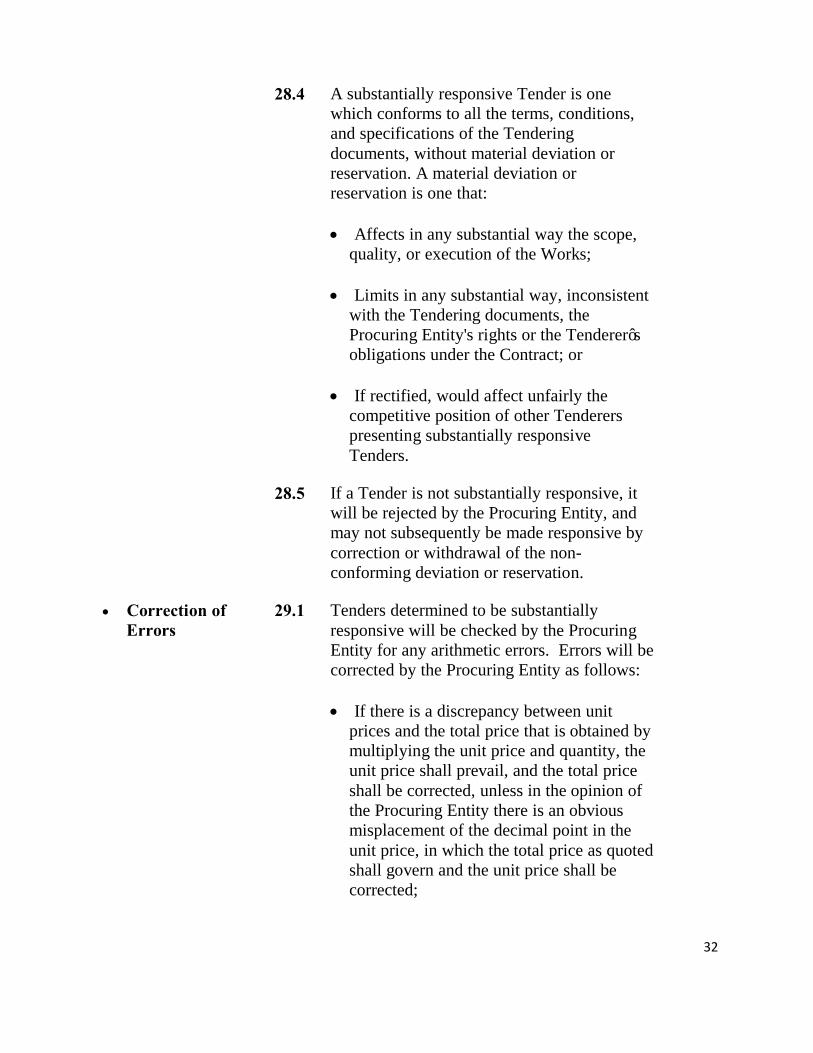
28.4 A substantially responsive Tender is one
which conforms to all the terms, conditions, and specifications of the Tendering documents, without material deviation or reservation. A material deviation or reservation is one that: • Affects in any substantial way the scope,
quality, or execution of the Works; • Limits in any substantial way, inconsistent
with the Tendering documents, the Procuring Entity's rights or the Tenderer’s obligations under the Contract; or
• If rectified, would affect unfairly the
competitive position of other Tenderers presenting substantially responsive Tenders.
28.5 If a Tender is not substantially responsive, it
will be rejected by the Procuring Entity, and may not subsequently be made responsive by correction or withdrawal of the non-conforming deviation or reservation.
• Correction of Errors
29.1 Tenders determined to be substantially responsive will be checked by the Procuring Entity for any arithmetic errors. Errors will be corrected by the Procuring Entity as follows: • If there is a discrepancy between unit
prices and the total price that is obtained by multiplying the unit price and quantity, the unit price shall prevail, and the total price shall be corrected, unless in the opinion of the Procuring Entity there is an obvious misplacement of the decimal point in the unit price, in which the total price as quoted shall govern and the unit price shall be corrected;

33
• If there is an error in a total corresponding to the addition or subtraction of subtotals, the subtotals shall prevail and the total shall be corrected; and
• Where there is a discrepancy between the
amounts in figures and in words, the amount in words will govern.
29.2 The amount stated in the Tender will, be
adjusted by the Procuring Entity in accordance with the above procedure for the correction of errors and, with, the concurrence of the Tenderer, shall be considered as binding upon the Tenderer. If the Tenderer does not accept the corrected amount, its Tender will then be rejected, and the Tender Security may be forfeited and the Tender Securing Declaration may be executed in accordance with sub-Clause 19.9.
• Conversion to Single Currency
30.1 To facilitate the evaluation and comparison, the Procuring Entity will convert all Tender prices expressed in the amounts in various currencies in which the Tender prices are payable to Kenya Shillings at the selling exchange rate established for similar transactions by the Central Bank of Kenya ruling on the date specified in the Tender Data Sheet.
• Comparison of Tenders
31.1 The Procuring Entity shall evaluate and compare only the Tenders determined to be substantially responsive in accordance with ITT Clause 28.
31.2 In evaluating the Tenders, the Procuring Entity will determine for each Tender the evaluated Tender price by adjusting the Tender price as follows: Making any correction for errors pursuant to ITT Clause 29; Excluding provisional sums and the provision, if any for contingencies in the Bill of

34
Quantities, but including Day work , where priced competitively ; and Making appropriate adjustments to reflect discounts or other price modifications offered in accordance with sub-Clause 24.5.
31.3 The Procuring Entity may waive any minor informality or non-conformity, which does not constitute a material deviation, provided such waiver does not prejudice or affect the relative standing of any Tenderer. Variations, deviations, and alternative offers and other factors, which are in excess of the requirements of the Tendering documents or otherwise result in unsolicited benefits for the Procuring Entity will not be taken into account in Tender evaluation.
• National Preference
32.1 In the evaluation of Tenders the Procuring Entity shall apply exclusive preference to citizens of Kenya where: • The funding is 100% from the Government
of Kenya or a Kenyan body; • The amounts are below the prescribed
threshold of KShs.200 million;
32.2 To qualify for the preference the candidate shall provide evidence of eligibility by: • Proving Kenyan citizenship by production
of a Kenyan Identity Card; or • Providing proof of being a “citizen
contractor” in terms of section 3(1) of the Act, i.e. being a natural person or an incorporated company wholly owned and controlled by persons who are citizens of Kenya.
32.3 The Minister of Finance may prescribe
additional preference and/or reservation schemes, for example for procurements above

35
these thresholds. If such additional preference schemes apply, details will be given in the Tender Data Sheet.
• Determination of the Lowest Evaluated Tender
33.1 The Tender with the lowest evaluated price from among those which are eligible, compliant and substantially responsive shall be the lowest evaluated Tender.
• Post-qualification of Tenderer
34.1 If specified in the Tender Data Sheet, post-qualification shall be undertaken.
34.2 The Procuring Entity will determine to its satisfaction whether the Tenderer that is selected as having submitted the lowest evaluated responsive Tender is qualified to perform the contract satisfactorily, in accordance with the criteria listed in sub-Clause 13.3.
34.3 The determination will take into account the Tenderer’s financial, technical, and production capabilities. It will be based upon an examination of the documentary evidence of the Tenderer’s qualifications submitted by the Tenderer, pursuant to sub-Clause 13.3, as well as such other information as the Procuring Entity deems necessary and appropriate. Factors not included in these Tendering documents shall not be used in the evaluation of the Tenderer’s qualifications.
34.4 An affirmative determination will be a prerequisite for award of the contract to the Tenderer. A negative determination will result in rejection of the Tenderer’s Tender, in which event the Procuring Entity will proceed to the next lowest evaluated Tender to make a similar determination of that Tenderer’s capabilities to perform satisfactorily.
• Award of Contract
• Criteria of Award 35.1 Subject to ITT Clause 35 and 36, the

36
Procuring Entity will award the Contract to the Tenderer whose Tender has been determined to be substantially responsive to the Tendering documents and who has offered the lowest Evaluated Tender Price, provided that such Tenderer has been determined to be: • Eligible in accordance with the
provisions of ITT Clause 3; • Is determined to be qualified to
perform the Contract satisfactorily; • Successful negotiations have been
concluded.
35.2 If, pursuant to sub-Clause 14.1, this Contract is being awarded on a “lot and package” basis, the lowest evaluated Tender price will be determined when evaluating this Contract in conjunction with other Contracts to be awarded concurrently, taking into account any discounts offered by the Tenderer for award of more than one Contract.
• Clarifications 36.1 Clarifications may be undertaken with the lowest evaluated Tenderer relating to the following areas:
• A minor alteration to the technical details of the statement of requirements;
• Reduction of quantities for budgetary
reasons, where the reduction is in excess of any provided for in the Tendering documents;
• A minor amendment to the Contract
Data Sheet; • Finalizing payment arrangements;

37
• Mobilization arrangements; • Agreeing final delivery or work
schedule to accommodate any changes required by the Procuring Entity;
• The methodology or staffing; or • Clarifying details that were not
apparent or could not be finalized at the time of Tendering.
36.2 Clarifications shall not change the
substance of the tender.
• Procuring Entity’s Right to Accept any Tender and to Reject any or all Tenders
37.1 Notwithstanding ITT Clause 35, the Procuring Entity reserves the right to accept or reject any Tender, and to cancel the Tendering process and reject all Tenders, at any time prior to the award of Contract, without thereby incurring any liability to the affected Tenderer or Tenderers.
37.2 Notice of the rejection of all Tenders shall be given promptly within 14 days to all Contractors that have submitted Tenders.
37.3 The Procuring Entity shall upon request communicate to any Tenderer the grounds for its rejection of its Tenders, but is not required to justify those grounds.
• Procuring Entities Right to Vary Quantities at the Time of Award
38.1 The Procuring Entity reserves the right at the time of contract award to increase or decrease the quantity of goods or related services originally specified in these Tendering documents (schedule of requirements) provided this does not exceed by the percentage indicated in the Tender Data Sheet, without any change in unit price or other terms and conditions of the Tender and Tendering documents.

38
• Notification of
Award 39.1 The Tenderer whose Tender has been
accepted will be notified of the award by the Procuring Entity prior to expiration of the Tender validity period by e-mail or facsimile confirmed by registered letter. This letter (hereinafter and in the Conditions of Contract called the "Letter of Acceptance") will state the sum that the Procuring Entity will pay the Contractor in consideration of the provision and maintenance of the Work(s) as prescribed by the Contract (hereinafter and in the Contract called the “Contract Price”).
39.2 The notification of award will constitute the formation of the Contract, subject to the Tenderer furnishing the Performance Security in accordance with ITT Clause 41 and signing the Contract in accordance with sub-Clause 40.2
39.3 At the same time as the person submitting the successful Tender is notified, the Procuring Entity will notify each unsuccessful Tenderer, the name of the successful Tenderer and the Contract amount and will discharge the Tender Security and Tender Securing Declaration of the Tenderer pursuant to ITT sub Clause 19.7.
39.4 If, after notification of award, a Tenderer wishes to ascertain the grounds on which it’s Tender or application for pre-qualification was unsuccessful, it should address its request to the secretary of the Tender Committee that authorized the award of contract. The secretary of the Tender Committee shall, within fourteen days after a request, provide written reasons as to why the Tender, proposal or application to be pre-qualified was unsuccessful. However, failure to take this
39
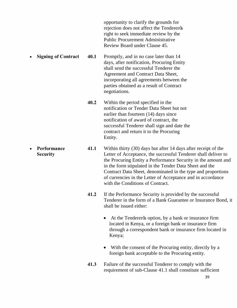
opportunity to clarify the grounds for rejection does not affect the Tenderer’s right to seek immediate review by the Public Procurement Administrative Review Board under Clause 45.
• Signing of Contract 40.1 Promptly, and in no case later than 14 days, after notification, Procuring Entity shall send the successful Tenderer the Agreement and Contract Data Sheet, incorporating all agreements between the parties obtained as a result of Contract negotiations.
40.2 Within the period specified in the notification or Tender Data Sheet but not earlier than fourteen (14) days since notification of award of contract, the successful Tenderer shall sign and date the contract and return it to the Procuring Entity.
• Performance Security
41.1 Within thirty (30) days but after 14 days after receipt of the Letter of Acceptance, the successful Tenderer shall deliver to the Procuring Entity a Performance Security in the amount and in the form stipulated in the Tender Data Sheet and the Contract Data Sheet, denominated in the type and proportions of currencies in the Letter of Acceptance and in accordance with the Conditions of Contract.
41.2 If the Performance Security is provided by the successful Tenderer in the form of a Bank Guarantee or Insurance Bond, it shall be issued either: • At the Tenderer’s option, by a bank or insurance firm
located in Kenya, or a foreign bank or insurance firm through a correspondent bank or insurance firm located in Kenya;
• With the consent of the Procuring entity, directly by a
foreign bank acceptable to the Procuring entity.
41.3 Failure of the successful Tenderer to comply with the requirement of sub-Clause 41.1 shall constitute sufficient

40
grounds for the annulment of the award and forfeiture of the Tender Security, in which event the Procuring Entity may make the award to the next lowest evaluated Tenderer or call for new Tenders.
• Advance Payment 42.1 The Procuring Entity will provide an Advance Payment as stipulated in the Conditions of Contract, subject to a maximum amount, as stated in the Tender Data Sheet.
42.2 The Advance Payment request shall be accompanied by an Advance Payment Security (Guarantee) in the form provided in Section X. For the purpose of receiving the Advance Payment, the Tenderer shall make an estimate of, and include in its Tender, the expenses that will be incurred in order to commence work. These expenses will relate to the purchase of equipment, machinery, materials, and on the engagement of labour during the first month beginning with the date of the Procuring Entity’s “Notice to Commence” as specified in the Contract Data Sheet.
• Adjudicator 43.1 The Procuring Entity proposes the person named in the Tender Data Sheet to be appointed as Adjudicator under the Contract, at an hourly fee specified in the Tender Data Sheet, plus reimbursable expenses. If the Tenderer disagrees with this proposal, the Tenderer should so state in the Tender. If, in the Letter of Acceptance, the Procuring Entity has not agreed on the appointment of the Adjudicator, the Adjudicator shall be appointed by the Appointing Authority designated in the Contract Data Sheet at the request of either party.
• Review of Procurement Decisions
• Right to Review 44.1 A Tenderer who claims to have suffered or
risk suffering, loss or damage or injury as a result of breach of a duty imposed on a Procuring Entity or an Approving Authority by the Public Procurement and Assets Disposal Act, 2015 and the Public Procurement and Disposal Regulations 2006, the procurement proceedings or processes, may seek administrative review as prescribed by the Act. The following matters, however, shall not be subject to the administrative

41
review: • The choice of procurement method; • a decision by the Procuring Entity to reject
all Tenders, proposals or quotations; • Where a contract is signed in accordance
to Section 68 of the Public Procurement and Disposal Act,2005;
• Where an appeal is frivolous.
• Time Limit on Review
45.1 The Tenderer shall submit an application for review in the number of copies and pay fees as prescribed by the Public Procurement and Disposal Regulations 2006 within fourteen (14) days of the time the Tenderer became or should have become aware of the circumstances giving rise to the complaint or dispute.
• Submission of Applications for Review by the Public Procurement Administrative Review Board
46.1 Any application for administrative review shall be submitted in writing to the Secretary, Public Procurement Administrative Review Board on Form RB 1 at the address shown in the Tender Data Sheet. The secretary to the review board shall immediately after filing of the request, serve a copy thereof on the Procuring Entity or Director-General as the case may be.
46.2 The application for administrative review shall be in accordance with the requirements of Regulation 73 of the Public Procurement and Disposals Regulations,2006, including: • Reasons for the complaint ,including any
alleged breach of the Act or Regulations; • An explanation of how the provisions of
the Act and or Regulation has been breached or omitted, including the dates and name of the responsible public officer,

42
where known; • Statements or other evidence supporting
the complaint where available as the applicant considers necessary in support of its request;
• Remedies sought; • Any other information relevant to the
complaint.
• Decision by the Public Procurement Administrative Review Board
47.1 The Administrative Review Board shall within thirty days after receipt of an application for administrative review deliver a written decision which shall indicate: • Annulling anything the Procuring Entity
has done in the procurement proceedings, including annulling the procurement proceedings in their entirety;
• Giving directions to the Procuring Entity
with respect to anything to be done or redone in the procurement proceedings;
• Substituting the decision of the Review
Board for any decision of the Procuring Entity in the procurement proceedings;
• Order the payment of costs as between
parties to the review.
47.2 The decision made by the Review Board shall, be final and binding on the parties unless judicial review thereof commences within fourteen (14) days from the date of the Review Board’s decision.
• Appeal on the decision of the Review Board
48.1 Any party to the review aggrieved by the decision of the Review Board may appeal to the High Court and the decision of the High Court shall be final.

43
SECTION III: TENDER DATA SHEET

44
Tender Data Sheet (TDS) Instructions to Tenderers Clause Reference
TDS Reference Number
ITT Clause Number
Amendments of, and Supplements to, Clauses in the Instruction to Tenderers
A. Introduction 1. 1.1 The Procuring Entity is
Kenya Railways Corporation P.O. Box 30121-00100 NAIROBI
2. 1.1 Name of Project is Proposed Renovation of Second Floor Block A at Kenya Railways Headquarters
3. 1.2 The expected completion date of the works is 6 months after site handover.
4. 1.3 The O bjectives of the Project are to:- Renovation of Second Floor, Block A Kenya Railways Headquarters.
5. 2.1 Name of the Procuring is Kenya Railways Corporation Financial Year 2017/2018 Works under the contracts:- • Partitioning W orks • Finishing and Painting • Carpentry, Joinery and Iron Mongery • Plumbing W orks • Electrical W orks
7. 5.1
Alternative Tenders are Not allowed in this Tender.
8. 5.2
Alternative time for completion Not applicable
9. 3.1 O nly Tenderers registered as Building Works in Class NCA 7 and above in the Contractors Registration with the National Construction Authority. This Tender is: Reserved Special Groups - Youth

45
10. 7.3
Pre-Tender meeting will not take place
B. Tendering Documents 12. 8.2 The number of copies to be completed and returned with the
Tender is 1 Original and 2Copies (Two).
13. 9.1 Address for clarification of Tendering Document is Kenya Railways Headquarters, Workshops Road off Haile Selassie Avenue, P.O. Box 30121-00100 NAIROBI
14. 9.2 Period to Respond to request for clarification by the Procuring Entity is 3(three) working days Period Prior to deadline for submission of Tenders for Tenderers to request clarification is 7 (seven) days
C. Preparation of Tenders 15.
11.1 Language of Tender and all correspondence shall be English
16. 13.3 Other information or materials required to be completed and submitted by Tenderers :
• Copies of original documents defining the constitution or legal status, place of registration, and principal, place of business; written power of attorney authorizing the signatory of the Tender to commit the Tenderer.
• Certified copy of Certificate of Incorporation, VAT registration, PIN registration and Valid Tax compliance certificate.
• The minimum required annual volume of construction
work for the successful Tenderer in any of the last 2 years shall be: Kshs 20,000,000/=
• Experience as prime contractor in the construction of at
least one project of a nature and complexity equivalent to the Works the last 2 years or the period stated in a) above (to comply with this requirement, works cited should be at least 70 percent complete).
• The essential equipment to be made available for the Contract by the successful Tenderer (proposals for timely acquisition or own, lease, hire, etc) shall be:

46
• 4X2 tippers payload 7 – 12 tonnes-2 No.
• Vibrating compaction plate 600 mm wide-2 No.
• Terrazo grinding machine-1 No.
• Mobile concrete Mixer-1 No.
• Concrete vibrators-3 No.
• A Site Manager with a minimum of 5 years experience in works of an equivalent nature and volume.
• Evidence of adequate working capital for this contract: The applicant shall demonstrate that it has access to, or has available, liquid assets, unencumbered real assets, lines of credit and other financial means sufficient to meet the construction cash flow for a period of three (3) months, estimated at Kshs.10 million, net of the applicant’s commitments for other contracts. The audited Accounts for the last two (2) years shall be submitted and must demonstrate the soundness of the applicant’s financial position, showing long-term profitability. Where necessary the procuring entity will make inquiries with the applicant’s bankers.
• Information regarding litigation, current: Litigation history the applicant should provide accurate information on any litigation or arbitration resulting from contracts completed or under its execution over the last five years. A consistent history of awards against the applicant or any partner of a joint venture may result in failure of the application.
17. 13.4 In the case of Joint Venture each partner shall submit information required under Clause ITT Clause 13.4.
18. 16.4 The price shall be fixed
19. 17.1
The currency in which the prices shall be quoted shall be: Kenyan Shilling.
20. 17.2 30.2
The authority for establishing the rates of exchange shall be Central Bank of Kenya.

47
The applicable date for exchange rates for tendering and evaluation purposes is 28 days earlier than the final deadline for the submission of tenders.
21. 18.1 The Tender validity period shall be 120 days.
22. 19.1 The bidder must submit a duly filled and signed Tender security declaration form.
23. 20.1
In addition to the 1 original of the Tender, the Tenderer should submit 2 copies of the Tender.
24. 20.2 Written confirmation of authorization is the power of the attorney.
D. Submission of Tenders 25. 21.2 a) Tenders shall be submitted to
Kenya Railways Corporation Workshops Road, Off Haile Selassie Avenue Procurement Department, First Floor NAIROBI
26. 21.2 b) Project name: Proposed Renovation of Second Floor Block A Kenya Railways Headquarters Tender number: KRC/PLM/010/2017-2018 Time and date for submission: On or before Thursday 2nd November, 2017 at 10.00am
27. 22.1 The deadline for Tender submission is • D ay: Thursday • D ate: 2nd November,2017 • Time :10:00am
28. 22.3 The extension of the deadline for submission of Tenders shall
be made not later than seven days before the expiry of the original deadline.
29 24.4 Expiry of Tender validity is 120days from date of opening of the tenders
E. Opening and Evaluation of Tenders 29. 25.1 The Tender opening shall take place at:
Workshops Road, Off Haile Selassie Avenue Kenya Railways Headquarters First Floor, Sattima Conference Room

48
Nairobi Kenya D ate: Thursday 2nd November, 2017 Time:10:00am
30. 32.3 Additional Preference is not applicable
31. 34.1 Post- qualification will be undertaken
32. 38.1 Percentage for goods and services increase or decrease is 10% Percentage for works increase or decrease is 15% Percentage for cumulative value of all contract variations shall not exceed 25% of total contract price.
F. Award of Contract 33. 41.1 The amount of Performance Security shall be 1% of the
Contract Price
34. 42.1 The A dvance Payment shall be 10% of the Contract Price
35. 43.1 The proposed adjudicator for the project will be as appointed by the chairman of the Chartered Institute of Arbitrators (Kenya Branch).
G. Review of Procurement Decisions 37. 46.1 The address for submitting appeals to A dministrative R
eview Board : The Secretary, Public Procurement Administrative R eview B oard , The Public Procurement R egulatory Authority, 10th Floor ,N ational B ank H ouse, P.O. B ox 58583-00200, N A IR O B I, Kenya. Tel: +254 (0) 20 3244000 Email: [email protected] Website: www.ppoa.go.ke

49
SECTION IV: GENERAL CONDITIONS OF CONTRACT

50
Table of Clauses A. General………………………………………………………………......… 51
1. Definitions………………………………………………………………… 51 2. Interpretation……………………………………………………………… 53 3. Language, Law, Fraud and Corruption…………………………………… 53 4. Confidentiality……………………………………………………………. 55 5. Project Manager’s Decisions……………………………………………… 56 6. Delegation………………………………………………………………… 56 7. Communications………………………………………………………….. 56 8. Subcontracting……………………………………………………………. .. 56 9. Other Contractors………………………………………………………… ... 56 10. Personnel…………………………………………………………………. ... 56 11. Procuring Entity’s and Contractor’s Risks………………………….......... 56 12. Procuring Entity’s Risks………………………………………………… 57 13. Contractor’s Risks………………………………………………………… 57 14. Insurance………………………………………………………………..... . 57 15. Site Investigation Reports………………………………………………… 58 16. Queries about the Contract Data Sheet…………………………………… 58 17. Contractor to Construct the Works……………………………………….. 58 18. Commencement and Completion……………………………………….. ... 58 19. Approval by the Project Manager………………………………………… 58 20. Protection of the Environment……………………………………………. 59 21. Labour Laws……………………………………………………………… 59 22. Health and Safety………………………………………………………… . 59 23. Discoveries……………………………………………………………….. . 60 24. Possession of the Site…………………………………………………….. . 60 25. Access to the Site………………………………………………………… . 60 26. Instructions, Inspections and Audits…………………………………….. .. 60 27. Disputes………………………………………………………………….... 60 28. Procedure for Disputes…………………………………………………… . 60 29. Replacement of Adjudicator……………………………………………... . 61
B. Time Control………………………………………………………......…….. 61
30. Programme……………………………………………………………….. . 61 31. Extension of the Intended Completion Date……………………………... . 62 32. Acceleration……………………………………………………………… . 62 33. Delays Ordered by the Project Manager…………………………………. . 62 34. Management Meetings…………………………………………………… . 62 35. Early Warning……………………………………………………………. . 62
C. Quality Control…………………………………………………......………. 63
36. Identifying Defects……………………………………………………… .... 63 37. Tests……………………………………………………………………… . 63 38. Correction of Defects……………………………………………………. .. 63 39. Uncorrected Defects……………………………………………………..... 63

51
D. Cost Control……………………………………………………………. 64 40. Bill of Quantities………………………………………………………… .. 64 41. Changes in the Quantities……………………………………………….. .. 64 42. Variations……………………………………………………………….. ... 64 43. Payments for Variations………………………………………………… ... 64 44. Cash Flow Forecasts…………………………………………………….. .. 65 45. Payment Certificates……………………………………………………. ... 65 46. Payments………………………………………………………………… .. 65 47. Compensation Events…………………………………………………… .... 66 48. Taxes……………………………………………………………………. ... 67 49. Currencies……………………………………………………………….. .. 68 50. Price Adjustment………………………………………………………… .... 68 51. Retention………………………………………………………………… .. 70 52. Liquidated Damages…………………………………………………….. .. 70 53. Bonus……………………………………………………………………. .. 71 54. Advance Payment……………………………………………………….. .. 71 55. Performance Securities………………………………………………….. .. 72 56. Day works……………………………………………………………….. .. 72 57. Cost of Repairs………………………………………………………….. ... 72
E. Finishing the Contract………………………………………………… 72
58. Completion Certificate………………………………………………….. ..... 72 59. Taking Over……………………………………………………………… . 72 60. Final Account…………………………………………………………… ... 72 61. Operating and Maintenance Manuals…………………………………… .. 73 62. Termination……………………………………………………………… .. 73 63. Payment upon Termination……………………………………………… .. 74 64. Property…………………………………………………………………. ... 75 65. Release from Performance……………………………………………… ... 75 66. Suspension of Financing………………………………………………… .... 75

52
• General • Definitions 1.1 Boldface type is used to identify defined terms.
The Adjudicator is the person appointed jointly by the Procuring Entity and the Contractor to resolve disputes in the first instance, as provided for in Clauses 27 and 28 hereunder.
Bill of Quantities means the priced and completed Bill of Quantities forming part of the Tender.
Compensation Events are those defined in Clause 47 hereunder.
The Completion Date is the date of completion of the Works as certified by the Project Manager, in accordance with Sub-Clause 58.1.
The Contract is the Contract between the Procuring Entity and the Contractor to execute, complete, and maintain the Works. It consists of the documents listed in Clause 2.3 below.
The Contractor is a person or corporate body whose Tender to carry out the Works has been accepted by the Procuring Entity.
The Contractor’s Tender is the completed Tendering document submitted by the Contractor to the Procuring Entity.
The Contract Price is the price stated in the Letter of Acceptance and thereafter as adjusted in accordance with the provisions of the Contract.
Days are calendar days; months are calendar months. Day works are varied work inputs subject to payment on
a time basis for the Contractor’s employees and Equipment, in addition to payments for associated Materials and Plant.
A Defect is any part of the Works not completed in accordance with the Contract.
The Defects Liability Certificate is the certificate issued by the Project Manager upon correction of defects by the Contractor.
The Defects Liability Period is the period named in the Contract Data Sheet and calculated from the Completion Date.

53
Drawings include calculations and other information provided or approved by the Project Manager for the execution of the Contract.
The Procuring Entity is the party who employs the Contractor to carry out the Works.
Equipment is the Contractor’s machinery and vehicles brought temporarily to the Site to construct the Works.
The Initial Contract Price is the Contract Price listed in the Procuring Entity’s Letter of Acceptance.
The Intended Completion Date is the date on which it is intended that the Contractor shall complete the Works. The Intended Completion Date is specified in the Contract Data Sheet. The Intended Completion Date may be revised only by the Project Manager by issuing an extension of time or an acceleration order.
Materials are all supplies, including consumables, used by the Contractor for incorporation in the Works.
Plant is any integral part of the Works that shall have a mechanical, electrical, chemical, or biological function.
The Project Manager is the person named in the Contract Data Sheet (or any other competent person appointed by the Procuring Entity and notified to the Contractor, to act in replacement of the Project Manager) who is responsible for supervising the execution of the Works and administering the Contract and shall be an “Architect” or a “Quantity Surveyor” registered under the Architects and Quantity Surveyors Act Cap 525 or an “Engineer” registered under Engineers Act 2011.
The Site is the area defined as such in the Contract Data Sheet.
Site Investigation Reports are those that were included in the Tendering documents and are factual and interpretative reports about the surface and subsurface conditions at the Site.
Specification means the Specification of the Works included in the Contract and any modification or addition made or approved by the Project Manager.
The Start Date is given in the Contract Data Sheet. It is the latest date when the Contractor shall commence

54
execution of the Works. It does not necessarily coincide with any of the Site Possession Dates.
A Subcontractor is a person or corporate body who has a Contract with the Contractor to carry out a part of the work in the Contract, which includes work on the Site.
Temporary Works are works designed, constructed, installed, and removed by the Contractor that are needed for construction or installation of the Works.
A Variation is an instruction given by the Project Manager that varies the Works.
The Works are what the Contract requires the Contractor to construct, install, and turn over to the Procuring Entity, as defined in the Contract Data Sheet.
“Force Majeure” means an event which is beyond the reasonable control of a Party and which makes a Party’s performance of its obligations under the Contract impossible or so impractical as to be considered impossible under the circumstances.
• Interpretation 2.1 In interpreting these Conditions of Contract, singular also means plural, male also means female or neuter, and the other way round. Headings have no significance. Words have their normal meaning under the language of the Contract unless specifically defined. The Project Manager will provide instructions clarifying queries about these Conditions of Contract.
2.2 If sectional completion is specified in the Contract Data Sheet, references in the Conditions of Contract to the Works, the Completion Date, and the Intended Completion Date apply to any Section of the Works (other than references to the Completion Date and Intended Completion Date for the whole of the Works).
2.3 The documents forming the Contract shall be interpreted in the order of priority given in the Contract Data Sheet:
(1) Agreement; (2) Letter of Acceptance;
(3) Contract Data Sheet; (4) Conditions of Contract;
(5) Technical Specifications; (6) Contractor’s Tender;

55
(7) Drawings; (8) Bill of Quantities; and
(9) Any other document listed in the Contract Data Sheet as forming part of the Contract.
• Language, Law, Fraud and Corruption
3.1 The language of the Contract and the law governing the Contract are stated in the Contract Data Sheet.
3.2 The Government requires that Procuring Entities (including beneficiaries of Government funded projects) as well as Tenderers/Suppliers/Contractors under Government financed contracts, observe the highest standard of ethics during the procurement and execution of such contracts. It is the responsibility of the Procuring Entity to ensure that Tenderers, suppliers, and contractors and their subcontractors observe the highest standard of ethics during the procurement and execution of such contracts. In pursuance of this policy:
For the purpose of this provision, the following
definitions are provided:
• “Corruption” has the meaning assigned to it in the Anti Corruption and Economic Crime Act 2003 and includes the offering, giving, receiving or soliciting of anything of value to influence the action of a public official in the procurement or disposal process or in contract execution;
• “Fraudulent Practice” includes a misrepresentation of fact in order to influence a procurement or disposal process or the execution of a contract to the detriment of the Procuring Entity and includes collusive practices amongst Tenderers prior to or after Tender submission designed to establish Tender prices at artificial non competitive levels and deprive the Procuring Entity of the benefits of free and open competition;
• “Collusive Practice” means an arrangement between two or more suppliers, contractors and subcontractors designed to achieve an improper purpose, including to influence improperly the actions of the Procuring Entity prior to or after Tender submission , designed

56
to establish Tender prices at artificial non competitive levels and to deprive the Procuring Entity of the benefit of free and open competition;
• “Coercive Practice” means impairing or harming, or threatening to impair or harm, directly or indirectly a supplier, contractor or subcontractor or the property of any of them to influence improperly the actions of a Procuring Entity;
• “Obstructive Practice” means deliberately destroying, falsifying, altering or concealing of evidence material to the investigation or making false statements to investigators in order to materially impede an investigation into allegations of a corrupt, fraudulent, coercive or collusive practice; and /or threatening, harassing or intimidating any party to prevent it from disclosing its knowledge of matters relevant to the investigation or from pursuing the investigation.
A Procuring Entity has the right to require that Tenderers, suppliers, and contractors and their subcontractors permit persons duly appointed by KACC/PPOA/KNAO to inspect their accounts and records and other documents relating to the Tender submission and contract performance;
The Procuring Entity will reject a proposal for award if it determines that the Tenderer recommended for award has engaged in corrupt, fraudulent practices or others stated under Clause 44.1.a in competing for the contract;
In pursuit of the policy defined in sub-Clause 44.1 the Procuring Entity will cancel the portion of the funds allocated to a contract for goods, works, or services if it at any time determines that corrupt or fraudulent practices were engaged in by representatives of the Procuring Entity or Approving Authority or of a beneficiary of the funds during the procurement or the execution of that contract;
In the event that the Procuring Entity or Approving Authority does not take timely and appropriate action satisfactory to the Government of Kenya to remedy

57
the situation, then the Director-General may order an investigation of procurement proceedings for the purpose of determining whether there has been a breach of the Public Procurement and Assets Disposal Act, 2015.
3.3 The Director-General may, on the advice of the Advisory Board, debar a person from participating in procurement proceedings on the ground that the person has committed an offence under the Public Procurement and Assets Disposal Act, 2015. A debarment shall be for a period of time of not less than five years. Before a person is so debarred, he/she will be given an opportunity to make representations to the Director-General and may request the Review Board to review the debarment.
3.4 Any communication between the Tenderers and the
Procuring Entity related to matters of alleged fraud or corruption must be made in writing.
• Confidentiality 4.1 The Service Providers, their Subcontractors, and the
Personnel of either of them shall not disclose any proprietary or confidential information relating to the Project, the Services, this Contract, or the Procuring Entity’s business or operations without the prior written consent of the Procuring Entity.
• Project Manager’s Decisions
5.1 Except where otherwise specifically stated, the Project Manager will decide contractual matters between the Procuring Entity and the Contractor in the role representing the Procuring Entity.
• Delegation 6.1 The Project Manager may delegate any of his duties and responsibilities to other people except to the Adjudicator, after notifying the Contractor, and may cancel any delegation after notifying the Contractor.
• Communications 7.1 Communications between parties that are referred to in the Conditions shall be effective only when in writing. A notice shall be effective only when it is delivered.
• Subcontracting 8.1 The Contractor may subcontract with the approval of the Project Manager, but may not assign the Contract without the approval of the Procuring Entity in writing. Subcontracting shall not alter the Contractor’s obligations.

58
• Other Contractors
9.1 The Contractor shall cooperate and share the Site with other contractors, public authorities, utilities, and the Procuring Entity between the dates given in the Schedule of Other Contractors, as referred to in the Contract Data Sheet. The Contractor shall also provide facilities and services for them as described in the Schedule. The Procuring Entity may modify the Schedule of Other Contractors, and shall notify the Contractor of any such modification
• Personnel 10.1 The Contractor shall employ the key personnel named in the Schedule of Key Personnel, as referred to in the Contract Data Sheet, who shall be appropriately qualified and registered with the appropriate bodies to carry out the functions stated in the Schedule or other personnel approved by the Project Manager. The Project Manager will approve any proposed replacement of key personnel only if their relevant qualifications and abilities are substantially equal to or better than those of the personnel listed in the Schedule.
• If the Project Manager asks the Contractor to remove a person who is a member of the Contractor’s staff or work force, stating the reasons, the Contractor shall ensure that the person leaves the Site within seven days and has no further connection with the work in the Contract.
• Procuring Entity’s and Contractor’s Risks
11.1 The Procuring Entity carries the risks which this Contract states are Procuring Entity’s risks, and the Contractor carries the risks which this Contract states are Contractor’s risks.
• Procuring Entity’s Risks
12.1 From the Start Date until the Defects Correction Certificate has been issued, the following are Procuring Entity’s risks:
• The risk of personal injury, death, or loss of or damage to property (excluding the Works, Plant, Materials, and Equipment), which are due to:
(i) Use or occupation of the Site by the Works or for the purpose of the Works, which is the unavoidable result of the Works; or
(ii) Negligence, breach of statutory duty, or interference with any legal right by the Procuring Entity or by any person employed by or contracted to him except the

59
Contractor.
• The risk of damage to the Works, Plant, Materials, and Equipment to the extent that it is due to a fault of the Procuring Entity or in the Procuring Entity’s design, or due to war or radioactive contamination directly affecting the country where the Works are to be executed.
12.2 From the Completion Date until the Defects Correction Certificate has been issued, the risk of loss of or damage to the Works, Plant, and Materials is an Procuring Entity’s risk except loss or damage due to:
(a) A Defect which existed on the Completion Date;
(b) An event occurring before the Completion Date, which was not itself an Procuring Entity’s risk; or
(c) The activities of the Contractor on the Site after the Completion Date.
• Contractor’s Risks
13.1 From the Starting Date until the Defects Correction Certificate has been issued, the risks of personal injury, death, and loss of or damage to property (including, without limitation, the Works, Plant, Materials, and Equipment) which are not Procuring Entity’s risks are Contractor’s risks.
• Insurance 14.1 The Contractor shall provide, in the joint names of the Procuring Entity and the Contractor, insurance cover from the Start Date to the end of the Defects Liability Period, in the amounts and deductibles stated in the Contract Data Sheet for the following events which are due to the Contractor’s risks:
(a) Loss of or damage to the Works, Plant, and Materials;
(b) Loss of or damage to Equipment;
(c) Loss of or damage to property (except the Works, Plant, Materials, and Equipment) in connection with the Contract; and
(d) Personal injury or death.
14.2 Policies and certificates for insurance shall be delivered by the Contractor to the Project Manager for the Project Manager’s approval before the Start Date. All such insurance shall provide for compensation to be payable
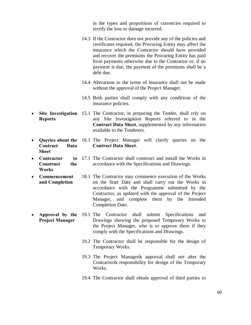
60
in the types and proportions of currencies required to rectify the loss or damage incurred.
14.3 If the Contractor does not provide any of the policies and certificates required, the Procuring Entity may affect the insurance which the Contractor should have provided and recover the premiums the Procuring Entity has paid from payments otherwise due to the Contractor or, if no payment is due, the payment of the premiums shall be a debt due.
14.4 Alterations to the terms of insurance shall not be made without the approval of the Project Manager.
14.5 Both parties shall comply with any conditions of the insurance policies.
• Site Investigation Reports
15.1 The Contractor, in preparing the Tender, shall rely on any Site Investigation Reports referred to in the Contract Data Sheet, supplemented by any information available to the Tenderers.
• Queries about the Contract Data Sheet
16.1 The Project Manager will clarify queries on the Contract Data Sheet.
• Contractor to Construct the Works
17.1 The Contractor shall construct and install the Works in accordance with the Specifications and Drawings.
• Commencement and Completion
18.1 The Contractor may commence execution of the Works on the Start Date and shall carry out the Works in accordance with the Programme submitted by the Contractor, as updated with the approval of the Project Manager, and complete them by the Intended Completion Date.
• Approval by the Project Manager
19.1 The Contractor shall submit Specifications and Drawings showing the proposed Temporary Works to the Project Manager, who is to approve them if they comply with the Specifications and Drawings.
19.2 The Contractor shall be responsible for the design of Temporary Works.
19.3 The Project Manager’s approval shall not alter the Contractor’s responsibility for design of the Temporary Works.
19.4 The Contractor shall obtain approval of third parties to

61
the design of the Temporary Works, where required.
19.5 All Drawings prepared by the Contractor for the execution of the temporary or permanent Works, are subject to prior approval by the Project Manager before their use.
• Protection of the Environment
20.1 The Contractors shall take all reasonable steps to protect the environment and to limit damage and nuisance to people and property resulting from pollution, noise and other results of his operations.
20.2 The Contractors shall ensure that emissions, surface discharges and effluent from his activities shall not exceed prescribed values in the environmental laws.
• Labour Laws • The Contractor shall comply with all the relevant labour laws applicable in the Country, including laws relating to workers employment, working hours, health, safety, welfare, and immigration, and shall allow them all their legal rights.
• The Contractor shall require his employees to obey all applicable laws, including those concerning safety at work.
• Health and Safety 22.1 The Contractor shall at all times take all reasonable precautions to maintain the health and safety of his personnel.
22.2 The Contractor shall ensure that first aid facilities are available at all times at the site and that suitable arrangements are made for all necessary welfare and hygiene requirements and for the prevention of epidemics.
22.3 The Contractor shall notify the Procuring Entity details of any accident as soon as practicable after its occurrence. The Contractor shall maintain records and make reports concerning health, safety, and welfare of persons, and damage to the property, as the Procuring Entity may reasonably require.
22.4 The Contractor shall conduct an HIV-Aids awareness programme, and shall take other such measures as specified in the Contract Data Sheet to reduce the risk of transfer of HIV virus between and among Contractor personnel, the Procuring Entity’s Staff and the surrounding community.

62
• Discoveries 23.1 Anything of historical or other interest or of significant value unexpectedly discovered on the Site shall be the property of the Procuring Entity. The Contractor shall notify the Project Manager of such discoveries and carry out the Project Manager's instructions for dealing with them.
• Possession of the Site
24.1 The Procuring Entity shall give possession of all parts of the Site to the Contractor. If possession of a part is not given by the date stated in the Contract Data Sheet, the Procuring Entity will be deemed to have delayed the start of the relevant activities, and this will be a Compensation Event.
• Access to the Site 25.1 The Contractor shall allow the Project Manager and any person authorized by the Project Manager access to the Site and to any place where work in connection with the Contract is being carried out or is intended to be carried out.
• Instructions, Inspections and Audits
26.1 The Contractor shall carry out all instructions of the Project Manager which comply with the applicable laws where the Site is located.
26.2 The Contractor shall permit the Kenya Government to inspect the Contractor’s accounts and records relating to the performance of the Contractor and to have them audited by auditors appointed by the Kenya Government, if so required by the Kenya Government
• Disputes 27. 1 If the Contractor believes that a decision taken by the Project Manager was either outside the authority given to the Project Manager by the Contract or that the decision was wrongly taken, the decision shall be referred to the Adjudicator within 14 days of the notification of the Project Manager’s decision.
• Procedure for Disputes
28.1 The Adjudicator shall give a decision in writing within 28 days of receipt of a notification of a dispute.
28.2 The Adjudicator shall be paid by the hour at the rate specified in the Tender Data Sheet and Contract Data Sheet, together with reimbursable expenses of the types specified in the Contract Data Sheet, and the cost shall be divided equally between the Procuring Entity and the Contractor, whatever decision is reached by the Adjudicator. Either party may refer a decision of the

63
Adjudicator to an Arbitrator within 28 days of the Adjudicator’s written decision. If neither party refers the dispute to arbitration within the above 28 days, the Adjudicator’s decision will be final and binding.
28.3 The arbitration shall be conducted in accordance with the arbitration procedure published by the institution named and in the place shown in the Contract Data Sheet.
• Replacement of Adjudicator
29.1 Should the Adjudicator resign or die, or should the Procuring Entity and the Contractor agree that the Adjudicator is not functioning in accordance with the provisions of the Contract, a new Adjudicator will be jointly appointed by the Procuring Entity and the Contractor. In case of disagreement between the Procuring Entity and the Contractor, within 30 days, the Adjudicator shall be designated by the Appointing Authority designated in the Contract Data Sheet at the request of either party, within 14 days of receipt of such request.
• Time Control • Programme 30.1 Within the time stated in the Contract Data Sheet, the
Contractor shall submit to the Project Manager for approval a Programme showing the general methods, arrangements, order, and timing for all the activities in the Works.
• An update of the Programme shall be a programme showing the actual progress achieved on each activity and the effect of the progress achieved on the timing of the remaining work, including any changes to the sequence of the activities.
30.3 The Contractor shall submit to the Project Manager for approval an updated Programme at intervals no longer than the period stated in the Contract Data Sheet. If the Contractor does not submit an updated Programme within this period, the Project Manager may withhold the amount stated in the Contract Data Sheet from the next payment certificate and continue to withhold this amount until the next payment after the date on which the overdue Programme has been submitted.
30.4 The Project Manager’s approval of the Programme shall not

64
alter the Contractor’s obligations. The Contractor may revise the Programme and submit it to the Project Manager again at any time. A revised Programme shall show the effect of Variations and Compensation Events
• Extension of the Intended Completion Date
31.1 The Project Manager shall extend the Intended Completion Date if a Compensation Event occurs or a Variation is issued which makes it impossible for Completion to be achieved by the Intended Completion Date without the Contractor taking steps to accelerate the remaining work, which would cause the Contractor to incur additional cost.
31.2 The Project Manager shall decide whether and by how much to extend the Intended Completion Date within 21 days of the Contractor asking the Project Manager for a decision upon the effect of a Compensation Event or Variation and submitting full supporting information. If the Contractor has failed to give early warning of a delay or has failed to cooperate in dealing with a delay, the delay by this failure shall not be considered in assessing the new Intended Completion Date.
• Acceleration 32.1 When the Procuring Entity wants the Contractor to finish before the Intended Completion Date, the Project Manager will obtain priced proposals for achieving the necessary acceleration from the Contractor. If the Procuring Entity accepts these proposals, the Intended Completion Date will be adjusted accordingly and confirmed by both the Procuring Entity and the Contractor.
32.2 If the Contractor’s priced proposals for acceleration are accepted by the Procuring Entity, they shall be incorporated in the Contract Price and treated as a Variation.
• Delays
Ordered by the Project Manager
33.1 The Project Manager may instruct the Contractor to delay the start or progress of any activity within the Works.
• Management Meetings
34.1 Either the Project Manager or the Contractor may require the other to attend a management meeting. The business of a management meeting shall be to review the plans for remaining work and to deal with matters raised in accordance with the early warning procedure.

65
34.2 The Project Manager shall record the business of management meetings and provide copies of the record to those attending the meeting and to the Procuring Entity. The responsibility of the parties for actions to be taken shall be decided by the Project Manager either at the management meeting or after the management meeting and stated in writing to all who attended the meeting.
• Early Warning
35.1 The Contractor shall warn the Project Manager at the earliest opportunity of specific likely future events or circumstances that may adversely affect the quality of the work, increase the Contract Price or delay the execution of the Works. The Project Manager may require the Contractor to provide an estimate of the expected effect of the future event or circumstance on the Contract Price and Completion Date. The estimate shall be provided by the Contractor as soon as reasonably possible.
35.2 The Contractor shall cooperate with the Project Manager in making and considering proposals for how the effect of such an event or circumstance can be avoided or reduced by anyone involved in the work and in carrying out any resulting instruction of the Project Manager.
• Quality Control • Identifying
Defects 36.1 The Project Manager shall check the Contractor’s work and
notify the Contractor of any Defects that are found. Such checking shall not affect the Contractor’s responsibilities. The Project Manager may instruct the Contractor to search for a Defect and to uncover and test any work that the Project Manager considers may have a Defect.
• Tests 37.1 If the Project Manager instructs the Contractor to carry out a test not specified in the Specification to check whether any work has a Defect and the test shows that it does, the Contractor shall pay for the test and any samples. If there is no Defect, the test shall be a Compensation Event.
• Correction of Defects
• The Project Manager shall give notice to the Contractor of any Defects before the end of the Defects Liability Period, which begins at Completion, and is defined in the Contract Data Sheet. The Defects Liability Period shall be extended for as long as Defects remain to be corrected.
• Every time notice of a Defect is given, the Contractor shall correct the notified Defect within the length of time

66
specified by the Project Manager’s notice.
• If the Contractor has not corrected a defect within the time specified in the Procuring Entity’s notice, a penalty for lack of performance will be paid by the Contractor. The amount to be paid will be calculated as a percentage of the cost of having the defect correct, assessed as described in Clause 39.
• Uncorrected Defects
39.1 If the Contractor has not corrected a Defect within the time specified in the Project Manager’s notice, the Project Manager will assess the cost of having the Defect corrected, and the Contractor will pay this amount.
• Cost Control • Bill of
Quantities 40.1 The Bill of Quantities shall contain items for the
construction, installation, testing, and commissioning work to be done by the Contractor.
40.2 The Bill of Quantities is used to calculate the Contract Price. The Contractor shall be paid for the quantity of the work done at the rate in the Bill of Quantities for each item.
• Changes in the Quantities
41.1 If the final quantity of the work done differs from the quantity in the Bill of Quantities for the particular item by more than 25 percent, provided the change exceeds 1 percent of the Initial Contract Price, the Project Manager shall adjust the rate to allow for the change.
41.2 The Project Manager shall not adjust rates from changes in quantities if thereby the Initial Contract Price is exceeded by more than 15 percent, except with the prior approval of the Procuring Entity.
41.3 If requested by the Project Manager, the Contractor shall provide the Project Manager with a detailed cost breakdown of any rate in the Bill of Quantities.
• Variations 42.1 All Variations shall be included in the updated Programmes produced by the Contractor.
• Payments for Variations
43.1 The Contractor shall provide the Project Manager with a quotation for carrying out the Variation when requested to do so by the Project Manager. The Project Manager shall assess the quotation, which shall be given within seven days of the request or within any longer period stated by

67
the Project Manager and before the Variation is ordered.
43.2 If the work in the Variation corresponds with an item description in the Bill of Quantities and if, in the opinion of the Project Manager, the quantity of work is above the limit stated in Sub-Clause 41.1 or the timing of its execution do not cause the cost per unit of quantity to change, the rate in the Bill of Quantities shall be used to calculate the value of the Variation. If the cost per unit of quantity changes, or if the nature or timing of the work in the Variation does not correspond with items in the Bill of Quantities, the quotation by the Contractor shall be in the form of new rates for the relevant items of work.
43.3 If the Contractor’s quotation is unreasonable, the Project Manager may order the Variation and make a change to the Contract Price, which shall be based on the Project Manager’s own forecast of the effects of the Variation on the Contractor’s costs.
43.4 If the Project Manager decides that the urgency of varying the work would prevent a quotation being given and considered without delaying the work, no quotation shall be given and the Variation shall be treated as a Compensation Event.
43.5 The Contractor shall not be entitled to additional payment for costs that could have been avoided by giving early warning.
• Cash Flow Forecasts
44.1 When the Programme is updated, the Contractor shall provide the Project Manager with an updated cash flow forecast. The cash flow forecast shall include different currencies, as defined in the Contract, converted as necessary using the Contract exchange rates.
• Payment Certificates
45.1 The Contractor shall submit to the Project Manager monthly statements of the estimated value of the work executed less the cumulative amount certified previously.
45.2 The Project Manager shall check the Contractor’s monthly statement and certify the amount to be paid to the Contractor within twenty eight 28 days of receipt of the certificate from the contractor.
45.3 The value of work executed shall be determined by the Project Manager.
45.4 The value of work executed shall comprise the value of the

68
quantities of the items in the Bill of Quantities completed.
45.5 The value of work executed shall include the valuation of Variations and Compensation Events.
45.6 The Project Manager may exclude any item certified in a previous certificate or reduce the proportion of any item previously certified in any certificate in the light of later information.
45.7 The Project Manager shall not be bound to certify any payment, if the net amount, after all retentions and deductions would be less than minimum amount of Interim Payment Certificate stated in the Contract Data Sheet.
• Payments 46.1 Payments shall be adjusted for deductions for advance payments and retention. The Procuring Entity shall pay the Contractor the amounts certified by the Project Manager within 28 days of the date of each certificate. If the Procuring Entity makes a late payment, the Contractor shall be paid interest on the late payment in the next payment Interest shall be calculated from the date by which the payment should have been made up to the date when the late payment is made at the prevailing rate of interest for commercial borrowing for each of the currencies in which payments are made as indicated in the Contract Data Sheet..
• If an amount certified is increased in a later certificate or as a result of an award by the Adjudicator or an Arbitrator, the Contractor shall be paid interest upon the delayed payment as set out in this clause. Interest shall be calculated from the date upon which the increased amount would have been certified in the absence of dispute.
46.3 Unless otherwise stated, all payments and deductions will be paid or charged in the proportions of currencies comprising the Contract Price.
46.4 Items of the Works for which no rate or price has been entered in will not be paid for by the Procuring Entity and shall be deemed covered by other rates and prices in the Contract.
• Compensation Events
47.1 The following shall be Compensation Events:
(a) The Procuring Entity does not give access to a part of the Site by the Site Possession Date stated in the Contract Data Sheet.

69
(b) The Procuring Entity modifies the Schedule of Other Contractors in a way that affects the work of the Contractor under the Contract.
(c) The Project Manager orders a delay or does not issue Drawings, Specifications, or instructions required for execution of the Works on time.
(d) The Project Manager instructs the Contractor to uncover or to carry out additional tests upon work, which is then found to have no Defects.
(e) The Project Manager unreasonably does not approve a subcontract to be let.
(f) Ground conditions are substantially more adverse than could reasonably have been assumed before issuance of the Letter of Acceptance from the information issued to Tenderers (including the Site Investigation Reports), from information available publicly and from a visual inspection of the Site.
(g) The Project Manager gives an instruction for dealing with an unforeseen condition, caused by the Procuring Entity, or additional work required for safety or other reasons.
(h) Other contractors, public authorities, utilities, or the Procuring Entity does not work within the dates and other constraints stated in the Contract, and they cause delay or extra cost to the Contractor.
(i) The advance payment is delayed.
(j) The effects on the Contractor of any of the Procuring Entity’s Risks.
(k) The Project Manager unreasonably delays issuing a Certificate of Completion.
(l) Other Compensation Events described in the Contract or determined by the Project Manager shall apply.
47.2 If a Compensation Event would cause additional cost or would prevent the work being completed before the Intended Completion Date, the Contract Price shall be increased and/or the Intended Completion Date shall be extended. The Project Manager shall decide whether and

70
by how much the Contract Price shall be increased and whether and by how much the Intended Completion Date shall be extended.
47.3 As soon as information demonstrating the effect of each Compensation Event upon the Contractor’s forecast cost has been provided by the Contractor, it shall be assessed by the Project Manager, and the Contract Price shall be adjusted accordingly. If the Contractor’s forecast is deemed unreasonable, the Project Manager shall adjust the Contract Price based on the Project Manager’s own forecast. The Project Manager will assume that the Contractor will react competently and promptly to the event.
47.4 The Contractor shall not be entitled to compensation to the extent that the Procuring Entity’s interests are adversely affected by the Contractor’s not having given early warning or not having cooperated with the Project Manager.
• Taxes 48.1 The Project Manager shall adjust the Contract Price if taxes, duties, and other levies are changed between the date 28 days before the submission of Tenders for the Contract and the date of the last Completion certificate. The adjustment shall be the change in the amount of tax payable by the Contractor, provided such changes are not already reflected in the Contract Price or are a result of Clause 50.
• Currencies 49.1 Where payments are made in currencies other than the Kenya Shillings, the exchange rates used for calculating the amounts to be paid shall be the exchange rates stated in the Contractor’s Tender.
• Price Adjustment
50.1 The amounts payable to the Contractor, in various currencies pursuant to Sub-Clause 45.1, shall be adjusted in respect of the rise or fall in the cost of labour, Contractor’s Equipment, Plant, materials, and other inputs to the Works, by applying to such amounts the formulae prescribed in this clause based on the prevailing consumer price index obtained from the Central Bureau of Statistics or the monthly inflation rate issued by the Central Bank of Kenya.
50.2 To the extent that full compensation for any rise or fall in costs to the Contractor is not covered by the provisions of this or other clauses in the Contract, the unit rates and prices included in the Contract shall be deemed to include

71
amounts to cover the contingency of such other rise or fall of costs.
50.3 The adjustment to be applied to amount payable to the Contractor as certified in Payment Certificates shall be determined formulae for each of the currencies in which the Contract Price is payable. No adjustment is to be applied to work valued on the basis of Cost or current prices. The formulae shall be as follows;
where; Pn is a price adjustment factor to be applied to the amount in each specific currency for the payment of the work carried out in the subject month, where such variations and day work are not otherwise subject to adjustment;
a is a constant, specified in the Appendix to Tender, representing the nonadjustable portion in contractual payments; b, c, d, etc., are weightings or coefficients representing the estimated proportion of each cost element (labour, materials, equipment usage, etc.) in the Works or sections thereof, net of Provisional Sums, as specified in the Appendix to Tender; the sum of a, b, c, d, etc., shall be one; Ln, Mn, En, etc., are the current cost indices or reference prices of the cost elements in the specific currency of origin for month “n,” determined pursuant to Sub-Clause 50.5, applicable to each cost element; and Lo, Mo, Eo, etc., are the base cost indices or reference prices corresponding to the above cost elements at the date specified in Sub-Clause 50.5
The value of net work done, certified by the Project Manager, in any monthly Interim or Final Certificate as payable by the Procuring Entity to the Contractor before deduction of any retention money shall be increased or decreased by an amount of ‘F’.
where;

72
The effective value Pc of work done which is to be subjected to increase or decrease shall be the difference between:
• the amount which, in the opinion of the Project Manager, is due to the Contractor under Clause 45 (before deduction of retention money and before deducting sums previously paid on account) less:
• any amount for payment or repayment of any advance payment;
• any amount for materials on site (if any); • any amounts for nominated sub-contractors (if any) • any amounts for any other items based on actual cost
or current prices; or • any sums for increase or decreases in the Contract
Price paid under this Sub-Clause and
• The amount calculated in accordance with (i) above of this Sub-clause and included in the last preceding statement.
50.4 The sources of indices shall be those listed in the
Appendix to Tender, as approved by the Engineer. Indices shall be appropriate for their purpose and shall relate to the Contractor’s proposed source of supply of inputs on the basis of which his Contract Price and expected foreign currency requirements shall have been computed. As the proposed basis for price adjustment, the Contractor shall have submitted with his Tender the tabulation of Weightings and Source of Indices in the Appendix to Tender, which shall be subject to approval by the Engineer.
50.5 The base cost indices or prices shall be those prevailing on
the day 28 days prior to the latest date for submission of Tenders. Current indices or prices shall be those prevailing on the day 28 days prior to the last day of the period to which a particular Interim Payment Certificate is related. If at any time the current indices are not available, provisional indices as determined by the Engineer will be used, subject to subsequent correction of the amounts paid to the Contractor when the current indices become available.
50.6 If the Contractor fails to complete the Works within the
time for completion prescribed under Clause 58 adjustment of prices thereafter until the date of completion of the Works shall be made using either the indices or prices relating to the prescribed time for

73
completion, or the current indices or prices, whichever is more favorable to the Procuring Entity, provided that if an extension of time is granted pursuant to Clause 28, the above provision shall apply only to adjustments made after the expiry of such extension of time.
50.7 The weightings for each of the factors of cost given in the
Appendix to Tender shall be adjusted if, in the opinion of the Engineer, they have been rendered unreasonable, unbalanced, or inapplicable as a result of varied or additional work already executed or instructed under Clause 43 or for any other reason.
• Retention 51.1 The Procuring Entity shall retain from each payment due
to the Contractor the proportion stated in the Contract Data Sheet until Completion of the whole of the Works.
51.2 On completion of the whole of the Works, half the total amount retained shall be repaid to the Contractor and the other half when the Defects Liability Period has passed and the Project Manager has certified that all Defects notified by the Project Manager to the Contractor before the end of this period have been corrected.
51.3 On completion of the whole Works, the Contractor may substitute retention money with an “on demand” Bank guarantee.
• Liquidated Damages
52.1 The Contractor shall pay liquidated damages to the Procuring Entity at the rate per day stated in the Contract Data Sheet for each day that the Completion Date is later than the Intended Completion Date. The total amount of liquidated damages shall not exceed the amount defined in the Contract Data Sheet. The Procuring Entity may deduct liquidated damages from payments due to the Contractor. Payment of liquidated damages shall not affect the Contractor’s liabilities.
• If the Intended Completion Date is extended after liquidated damages have been paid, the Project Manager shall correct any overpayment of liquidated damages by the Contractor by adjusting the next payment certificate. The Contractor shall be paid interest on the overpayment, calculated from the date of payment to the date of repayment, at the rates specified in Sub-Clause 46.1.
• If the Contractor has not corrected a defects within the time specified in the Procuring Entity’s notice, the

74
Procuring Entity will assess the cost of having the defect corrected, the Contractor will pay this amount, and a penalty for lack of performance calculated as described in Clause 38.
• Bonus 53.1 The Contractor shall be paid a Bonus calculated at the rate per calendar day stated in the Contract Data Sheet for each day (less any days for which the Contractor is paid for acceleration) that the Completion is earlier than the Intended Completion Date. The Project Manager shall certify that the Works are complete, although they may not be due to be complete.
• Advance Payment
54.1 The Procuring Entity shall make advance payment to the Contractor of the amounts stated in the Contract Data Sheet by the date stated in the Contract Data Sheet, against provision by the Contractor of an Unconditional Bank Guarantee in a form and by a bank acceptable to the Procuring Entity in amounts and currencies equal to the advance payment. The Guarantee shall remain effective until the advance payment has been repaid, but the amount of the Guarantee shall be progressively reduced by the amounts repaid by the Contractor. Interest will not be charged on the advance payment.
54.2 The Contractor is to use the advance payment only to pay for Equipment, Plant, Materials, and mobilization expenses required specifically for execution of the Contract. The Contractor shall demonstrate that advance payment has been used in this way by supplying copies of invoices or other documents to the Project Manager.
54.3 The advance payment shall be repaid by deducting proportionate amounts from payments otherwise due to the Contractor, following the schedule of completed percentages of the Works on a payment basis. No account shall be taken of the advance payment or its repayment in assessing valuations of work done, Variations, price adjustments, Compensation Events, Bonuses, or Liquidated Damages.
• Performance Securities
55.1 The Performance Security shall be provided to the Procuring Entity no later than the date specified in the Letter of Acceptance and shall be issued in an amount and form and by a bank or surety acceptable to the Procuring Entity, and denominated in the types and proportions of the currencies in which the Contract Price is payable. The Performance Security shall be valid until a date 28 days

75
from the date of issue of the Certificate of Completion in the case of a Bank Guarantee, and until one year from the date of issue of the Completion Certificate in the case of a Performance Bond.
• Day works 56.1 If applicable, the Day works rates in the Contractor’s Tender shall be used for small additional amounts of work only when the Project Manager has given written instructions in advance for additional work to be paid for in that way.
56.2 All work to be paid for as Day works shall be recorded by the Contractor on forms approved by the Project Manager. Each completed form shall be verified and signed by the Project Manager within two days of the work being done.
56.3 The Contractor shall be paid for Day works subject to obtaining signed Day works forms.
• Cost of Repairs 57.1 Loss or damage to the Works or Materials to be incorporated in the Works between the Start Date and the end of the Defects Correction periods shall be remedied by the Contractor at the Contractor’s cost if the loss or damage arises from the Contractor’s acts or omissions.
• Finishing the Contract • Completion
Certificate 58.1 The Contractor shall request the Project Manager to issue a
certificate of Completion of the Works, and the Project Manager will do so upon deciding that the work is completed.
• Taking Over 59.1 The Procuring Entity shall take over the Site and the Works within seven days of the Project Manager’s issuing a certificate of Completion.
• Final Account 60.1 The Contractor shall supply the Project Manager with a detailed account of the total amount that the Contractor considers payable under the Contract before the end of the Defects Liability Period. The Project Manager shall issue a Defects Liability Certificate and certify any final payment that is due to the Contractor within 56 days of receiving the Contractor’s account if it is correct and complete. If it is not, the Project Manager shall issue within 56 days a schedule that states the scope of the corrections or additions that are necessary. If the Final Account is still unsatisfactory after it has been resubmitted, the Project Manager shall decide on the amount payable to the

76
Contractor and issue a payment certificate.
• Operating and Maintenance Manuals
61.1 If “as built” Drawings and/or operating and maintenance manuals are required, the Contractor shall supply them by the dates stated in the Contract Data Sheet.
61.2 If the Contractor does not supply the Drawings and/or manuals by the dates stated in the Contract Data Sheet, or they do not receive the Project Manager’s approval, the Project Manager shall withhold the amount stated in the Contract Data Sheet from payments due to the Contractor.
• Termination 62.1 The Procuring Entity or the Contractor may terminate the Contract if the other party causes a fundamental breach of the Contract.
62.2 Fundamental breaches of Contract shall include, but shall not be limited to, the following:
(a) The Contractor stops work for 28 days when no stoppage of work is shown on the current Programme and the stoppage has not been authorized by the Project Manager;
(b) The Project Manager instructs the Contractor to delay the progress of the Works, and the instruction is not withdrawn within 28 days;
(c) The Procuring Entity or the Contractor is made bankrupt or goes into liquidation other than for a reconstruction or amalgamation;
(d) A payment certified by the Project Manager is not paid by the Procuring Entity to the Contractor within 84 days of the date of the Project Manager’s certificate;
(e) The Project Manager gives Notice that failure to correct a particular Defect is a fundamental breach of Contract and the Contractor fails to correct it within a reasonable period of time determined by the Project Manager;
(f) The Contractor does not maintain a Security, which is required; and
(g) The Contractor has delayed the completion of the Works by the number of days for which the maximum amount of liquidated damages can be paid, as defined in the Contract Data Sheet.

77
(h) If the Contractor, in the judgment of the Procuring Entity has engaged in corrupt or fraudulent practices in competing for or in executing the Contract.
For the purpose of this paragraph:
“corrupt practice” means the offering, giving, receiving or soliciting of anything of value to influence the action of a public official in the procurement process or in contract execution and includes inter alia, bribery and extortion or coercion which involves threats of injury to person ,property or reputation, and.
“fraudulent practice” means a misrepresentation of facts in order to influence a procurement process or the execution of a contract to the detriment of the Procuring Entity, and includes collusive practice among Tenderers (prior to or after Tender submission) designed to establish Tender prices at artificial non-competitive levels and to deprive the Procuring Entity of the benefits of free and open competition.
62.3 When either party to the Contract gives notice of a breach of Contract to the Project Manager for a cause other than those listed under Sub-Clause 62.2 above, the Project Manager shall decide whether the breach is fundamental or not.
62.4 Notwithstanding the above, the Procuring Entity may terminate the Contract for convenience.
62.5 If the Contract is terminated, the Contractor shall stop work immediately, make the Site safe and secure, and leave the Site as soon as reasonably possible.
• Payment upon Termination
63.1 If the Contract is terminated because of a fundamental breach of Contract by the Contractor, the Project Manager shall issue a certificate for the value of the work done and Materials ordered less advance payments received up to the date of the issue of the certificate and less the percentage to apply to the value of the work not completed, as indicated in the Contract Data Sheet. Additional Liquidated Damages shall not apply. If the total amount due to the Procuring Entity exceeds any payment due to the Contractor, the difference shall be a debt payable to the Procuring Entity.
63.2 If the Contract is terminated for the Procuring Entity’s

78
convenience or because of a fundamental breach of Contract by the Procuring Entity, the Project Manager shall issue a certificate for the value of the work done, Materials ordered, the reasonable cost of removal of Equipment, repatriation of the Contractor’s personnel employed solely on the Works, and the Contractor’s costs of protecting and securing the Works, and less advance payments received up to the date of the certificate.
• Property 64.1 All Materials on the Site, Plant, Equipment, Temporary Works, and Works shall be deemed to be the property of the Procuring Entity if the Contract is terminated because of the Contractor’s default.
• Release from Performance
65.1 If the Contract is frustrated by the outbreak of war or by any other event entirely outside the control of either the Procuring Entity or the Contractor, the Project Manager shall certify that the Contract has been frustrated. The Contractor shall make the Site safe and stop work as quickly as possible after receiving this certificate and shall be paid for all work carried out before receiving it and for any work carried out afterwards to which a commitment was made.
• Suspension of Financing
66.1 In the event that the source of financing is suspended to the Procuring Entity, from which part of the payments to the Contractor are being made:
(a) The Procuring Entity is obligated to notify the Contractor of such suspension within 7 days of having received the financing agency’s suspension notice.
(b) If the Contractor has not received sums due it within the 28 days for payment provided for in Sub-Clause 46.1, the Contractor may immediately issue a 14-day termination notice.

79
SECTION V: CONTRACT DATA SHEET (CDS)

80
Contract Data Sheet Instructions for completing the Contract Data Sheet CDS Clause
GCC Clause
Description
1
1.1
• General The Procuring Entity is Kenya Railways Corporation P.O. Box 30121-00100 NAIROBI The Adjudicator shall be appointed by the Chartered Institute of Arbitrators (Kenya Branch). The Defects Notification Period is six (6) months from practical completion of works The Contractor Manager is Project Manager, Kenya Railways The name and identification number of the Contract is Proposed Renovations of the Second Floor, Block A Kenya Railways Headquarters. Tender No. KRC/PLM/010/2017-2018 The Start Date shall be as agreed with the Project Engineer. The Intended Completion D ate for the whole of the W orks shall be 9 Months from date of Site hand over. The following documents also form part of the Contract:
(1) Agreement; (2) Letter of Acceptance; (3) Contract Data Sheet; (4) Conditions of Contract; (5) Technical Specifications; (6) Contractor’s Tender; (7) Drawings; (8) Bill of Quantities
The Site is located at Kenya Railways Headquarters - Nairobi

81
2. 2.2 Sectional completion is not applicable
3. 2.3(9) List other documents that form part of the contract if any: Standard Specifications for Building works
4. 3.1 The language of the Contract documents is English The law that applies to the Contract is the Kenyan Law.
5. 9.1 Schedule of Other Contractors, if any: Electrical contractor
6. 10.1 Schedule of Key Personnel. The applicant must have suitably qualified personnel to fill the following managerial and supervisory positions
Position Minimum Qualification
Total experience (years)
In similar works (years)
As manager/supervisor of similar works (years)
Site Agent
Degree in Engineering/ Project Management
5 3 3
Foreman- building Works
Diploma in Civil/ Building Eng.
3 2 2
7. 14.1 The minimum Insurance covers shall be:
(a) Loss of or damage to the Works, Plant, and Materials: Full
replacement cost but not less than the contract price
(b) Loss of or damage to Equipment: Full Replacement Cost
(c) Loss of or damage to property (except the Works, Plant, Materials, and Equipment) in connection with the Contract: Full Replacement Cost.
(d) Personal injury or death
• For contractor’s employees- Ksh 3 million
• For other people- Ksh 3million
8. 15.1 Site Investigation Reports available to the Tenderers are: N/A
9. 22.4 The other measures include: • Minimizing the number of migrant workers employed on the project

82
and household in the site camp • Providing access to Voluntary Counselling and Testing (VCT)
• Providing psychological support and health care including
prevention and treatment of opportunistic infections for workers infected and affected, as well as their families
• Providing condoms (male and female) to workers
10. 24.1 &
47.1 The Site Possession Date shall be: Seven (7) days after Engineers order to commence.
11. 28.2 Hourly Rate of Fees payable to the Adjudicator shall be as recommended by the Chartered Institute of Arbitrators (Kenya Branch) Types of reimbursable expenses to be paid to the Adjudicator shall be as provided for in the rules of the Chartered Institute of Arbitrators (Kenya Branch).
12. 28.3 Arbitration will take place in accordance with the Laws of Kenya and the Arbitration Rules of the Chartered Institute of Arbitrators (Kenya Branch) by one or more arbitrators appointed by the Chartered Institute of Arbitrators (Kenya Branch).
13. 29.1 Appointing Authority for the Adjudicator: Chairman, Institute of Arbitration of Kenya
• Time Control
14. 30.1 The Contractor shall Submit a Programme for the Works within 7 days of
delivery of the Letter of Acceptance.
15. 30.3 The period between Programme updates is 14 days.
16. 30.3 The amount to be withheld by the Project Manager in the case the contractor does not submit an updated programme is: Ksh 100,000/= until program is submitted
• Quality Control 17. 38.1 The Defects Notification Period is 6 months from practical completion.
• Cost Control
18. 45.7 Minimum Amount of Interim Payment Certificate will be 5 million shillings 19. 46.1 The interest rate shall be 2% above the average lending rate from Central
Bank of Kenya

83
20. 47.1(a) The Site Possession Date shall be: Seven (7) days after Engineers order to commence.
21. 50 The contract is not subject to price adjustment in accordance with Clause 50 of the General Conditions of Contract.
22. 51.1 The amount of retention is 10% of value of works of Interim Payment Certificate’.
Limit of retention will be 10% of contract price.
23. 52.1 The rate of liquidated damages is 0.15% of contract price per day.
52.1 62.2 (g)
The maximum amount of liquidated damages is 10% of contract price
24. 53.1 The bonus for early completion is Not applicable
25. 54.1 The amount of advance payment shall be 10 per cent of the contract sum against an unconditional bank guarantee approved by the Employer
Monthly Recovery of Advance Payment: Recovery of the advance will start on the next certificate following the one attaining 20% of the contract sum The advance repayment amount shall be determined by means of the formula
Ri= A(xi – xii) 80-20 where Ri = The amount to be recovered A= The amount of advance which was been granted Xi= The amount of the proposed cumulative payments as a
percentage of the original amount of the contract. This figure will exceed 20 % but not exceed 80 %.
Xii = the amount of the previous cumulative payments as a
percentage of the original amount of the contract. This will be below 80 % but not less than 20 %.
26. 55.1 The Performance Security shall be 1% of the contract price
• Finishing the Contract
27. 61.1 Operating manual shall be supplied by the contractor by : Not applicable

84
28. 61.2 The amount to be withheld by the Project Manager in the case the contractor
does not submit operating manual is: Not applicable
29. 63.1 The percentage to apply to the value of the work not completed, representing the Procuring Entity's additional cost for completing the Works, is 15%

85
SECTION 6: QUALIFICATION CRITERIA
This Section contains all the factors, methods and criteria that the Employer shall use to evaluate applications. The information to be provided in relation to each factor and the definitions of the corresponding terms are included in the respective Application Forms.

86
A. PRELIMINARY/MANDATORY REQUIREMENTS
A. MANDATORY REQUIREMENT REQUIREMENT COMPLIED
1 Copy of Valid Certificate of Incorporation / Registration Mandatory
2 Copy of a Valid KRA Tax compliance Certificate Mandatory
3 Copies of Certified Audited Accounts for any of the 2 (Two) consecutive years ( 2014, 2015,2016)
Mandatory
4 Must provide a Contact address: Physical, Postal, Telephone and Email address of the Firm (Confidential Business Questionnaire) Clearly indicating the list of Directors or Partners as applicable.
Mandatory
5 Bidder Must provide copy of registration with NCA 7 and above as a Building Works Contractor, Certificate must be accompanied by a current practicing certificate.
Mandatory
6 Copy of a Valid Registration certificate with National Treasury – Special Group – Youth Only
Mandatory
7 Bidder Must filled, signed and stamped Tender Security declaration form.
Mandatory
8 Litigation History ( Provided in Form 7 Litigation History form in the tender Document filled, signed and stamped)
Must Declare
9 Bidder must fill the Integrity Declaration Forms (Form 8) provided in the Tender Document.
Must Declare
10 Attach Pre-Tender Site Visit Certificate (Bidder Must make arrangement and attend Site visit and have certificate signed by KR Representative)
Mandatory
11 Bidders should have their documents paginated (serialized) to ensure compliance with Section 74 (i) Public Procurement and Assets Disposal Act, 2015 (in format 1,2,3,4……..to the last page)
Mandatory
Bidders must meet all the Mandatory Requirement to proceed to Technical Evaluation Stage

87
B. TECHNICAL REQUIREMENTS
B. TECHNICAL EVALUATION
YES/NO
1 Specific experience of the firm
Experience as prime contractor in the construction. Bidder Must provide evidence of two projects of a nature and complexity equivalent to the Works in the last 2 years (Scope and cost).
Bidders Must attach Certified copies of Contracts/LPOs for each assignment
Mandatory
2. The Bidder must Provide evidence to show his Annual volume of construction of a minimum of Kshs 20,000,000 carried out in any of the last 2 years
Mandatory
3. The Bidder must indicate the main plant and equipment considered by the company to be necessary for undertaking the project together with proof of ownership
The essential equipment to be made available for the Contract by the Bidder (proposals for timely acquisition or own, lease, hire, etc) shall be:
1. 4X2 tippers payload 7 – 12 tonnes 2No.
2. Terrazo grinding machine 1 No
3. Concrete Mixer 1. No
4. Concrete vibrators..............................................1No
Bidder Must provide evidence of ownership or lease agreement for the equipment.
Mandatory
4 Personnel
Bidder should provide evidence of technical Training and Experience of Bidders staff;
Site Agent Qualification
Degree in Civil Eng/Project Management or equivalent
Mandatory

88
construction qualification
General Experience = 5yrs
Specific Experience = 3yrs
Foreman Building Works
Qualification = Diploma Civil Eng
General Experience = 3yrs
Specific Experience = 2yrs
Must provide CV and Academic and Professional Certificates for the Key Staff above
Bidder Must Comply with all the Technical Requirement to proceed for Financial Evaluation.
C. FINANCIAL EVALUATION CRITERIA Kenya Railways will make award to the lowest evaluated tender. That is the lowest priced tender meeting all the Mandatory and Technical Requirements.

89
SECTION VI: TECHNICAL SPECIFICATIONS The works shall be executed in accordance with the following specifications and Manuals:

90
GENERAL SPECIFICATIONS PART I
BUILDERS WORKS

91
BUILDERS WORKS SPECIFICATION OF WORKMANSHIP AND MATERIALS
• GENERAL
• SCOPE OF WORKS The earthworks to be executed under the Contract comprise: - Clearing of the site. - Grubbing and grading of the pavement and construction zone. - Fill up to formation level for subbase, and for topsoil and backfilling around the foundations as specified on the drawings or directed by the Engineer. - Haulage and disposal of excess excavated material. - Supply and transport of imported filling.
• SETTING OUT - LEVELLING - ORIGINAL POINTS AND LEVELS Before the works commence, the Contractor shall proceed to set out the various
subgrades and base lines, at his own cost and subject to the approval of the Consultants.
If, for whatever reason, the nominal levels of the reference marks are modified, the Contractor shall make the necessary changes and have them approved by the Engineer.
• EXCAVATION AND EARTHWORKS
• STRUCTURES ENCOUNTERED DURING EXCAVATION WORK
No brickwork, pipes, etc. encountered during the excavation may be demolished until an
enquiry has demonstrated that these structures or installations do not form part of a privately or publicly owned or functioning installation.
The Contractor shall submit for approval documents and drawings indicating all the items encountered during excavation, such as old brickwork, pipes etc.
Demolition of structures encountered during the excavation will be paid for on presentation of documents to be approved.
• MAINTENANCE OF SUBBASES, BASES AND SITE ROADS For the whole duration of the work and until the taking over, the Contractor shall take
special care of the subbases, bases and their shoulders. He shall take all necessary steps to avoid that they are damaged either as a consequence of the work or by heavy rain or similar.
During backfilling procedures the Contractor is obliged to carry out the work in an

92
appropriate manner and take the necessary measures to protect the backfilling material.
The Contractor alone is responsible for whatever damage may befall the subbases and bases and he is obliged to see their repair and maintenance at his own cost.
• DEMOLITION OF EXISTING CONSTRUCTIONS
These have been taken provisionally under the measured work.
• STRIPPING OF TOP SOIL
Stripping shall mean digging away the top soil and putting this soil aside for later use or haulage of this material from the site.
In principle the stripping work shall be carried out by means of a bulldozer and the top soil
shall be deposited in recommended places approved by the Architect/Engineer and easily accessible for loading vehicles.
Where the stripped topsoil consists of dark grey clay with occasional phonolite fragments,
the clay soil, named cotton soil, is highly expansive and it is absolutely vital that this clay soil be removed underneath all structures and paved areas and taken to tip.
A stockpile of top soil if approved for future use shall be kept for later covering of non paved
areas in a thickness of 200 mm.
• CLASSIFICATION OF EXCAVATED MATERIAL Excavated materials shall be classified as follows and earthwork in each of the classes
measured separately.
• ORDINARY SOIL By ordinary soil is understood: such material as does not necessitate the use of a ripper,
nor the use of explosives. Generally any material which yields to the ordinary application of shovel or pick axe such as stiff clay, murram, sand, gravel including boulders with a volume not larger than 0.5 cubic meter.
Boulders larger than 0.5 cubic metre shall be classified as soft or hard rock as defined
below.
• SOFT ROCK, HARD SOIL
By this is meant: such material as is not covered by the category above, but which can normally be dug out by means of a ripper with one tooth mounted on a tractor with three hundred and fifty (350) H.P. or more. This material shall include coral rock, highly consolidated and strongly cemented murram and gravel mixed with boulders of hard rock not larger than 0.5 cubic metre. • HARD ROCK
By this material is meant such material as cannot be removed by ordinary earthwork
machinery or by the ripper. It shall comprise boulders 0.5 cubic meter in volume or greater

93
and all rock in ledges, bedded deposits, and conglomerate deposits so firmly cemented as to present all the characterizes of solid rock. This soil type involves loosening and breaking by blasting and digging out and removal of the thus loosened ground.
Rock, boulders or gravel required by the contractor for future use in the works shall be
neatly stacked where required or as otherwise approved or directed.
• PROTECTION OF PIPES, CABLES, ETC.
Before commencing works which include excavations or ground levelling by manual or mechanical excavation the Contractor shall at his own expense ascertain in writing from the Post Office, Kenya Power & Lighting Co. Ltd., Engineer's Department (Water and Sewers Section) and all other Public Bodies, Companies and Persons who may be affected, the position and depth of their respective ducts, cables, mains or pipes and appurtenances. He shall thereupon search for and locate such services.
The Contractor shall at his own expense effectually prop, protect, underpin, alter, divert, restore and make good as may be necessary all pipes, cables or ducts, poles or wires and their appurtenances disturbed or damaged during the progress of the works, or consequence thereof.
Except that such services as required to be removed or altered by virtue of the layout of the permanent work and not the manner in which the work is carried out, shall be so removed or altered at the expense of the Employer.
The Contractor shall be liable for the cost of repairs to any services damaged as a result of carrying out the Works and shall further be liable for any damage which may be shown during the period of maintenance, to have arisen through the execution of these works.
• EXCAVATION BELOW REQUIRED DEPTH
Should any excavations be made below the levels shown or required to obtain a
solid bottom, the Contractor shall, at his own expense, satisfactorily fill in such extra depth and width with concrete similar to that described for foundations or as directed by the Architect/Engineer.
• BACKFILLING AROUND CONSTRUCTIONS
Backfilling underneath future foundations shall be performed with lean concrete Class 15. For other backfilling materials as stated in clause above shall be used and compaction shall be in as described below.
Where the CBR value of the fill material obtained from general excavation is less than 8%
at BS Compaction after 48 hours soaking, then the Engineer shall instruct the Contractor to provide selected fill in the upper layer or layers of the embankment. The thickness of the selected fill material shall be determined by the Engineer.
• PLACING AND COMPACTION OF BACKFILL
The backfill shall be filled in and compacted methodically; it shall be spread in layers of max

94
200 mm thickness. If the Contractor has powerful compaction (vibration roller) equipment at his disposal, this layer may be increased to 400 mm on the written approval of the Engineer.
If the moisture content is inferior to the optimum value, the Contractor shall sprinkle the
backfill with water. Also, he shall pay special attention to the compaction procedures for the areas along the edges. For this purpose he must give the edges a little excess fill so as to produce a slight inclination towards the middle of the backfilled area. Compaction of the shoulders may be carried out with a vibration roller whose centre of gravity can be shifted towards the middle of the backfilled area.
During the placing and compaction of the backfill the Contractor shall make sure that the
works in reinforced concrete are well protected so that no harm befalls them. In forming embankments, the Contractor shall make due allowance in height and width for
consolidation and shrinkage. On the completion of the Contract, the levels, width and dimensions of the finished surfaces of embankments shall correspond to the levels and dimensions shown on the Drawings.
• HARDCORE FILLING
Hardcore filling under floors etc. shall be good hard stone ballast or quarry waste to the approval of the Architect and or Engineer broken to pass not greater than a 150 mm ring or to be 75% of the finished thickness of the layers being compacted whichever is the lesser. Hardcore shall be free from all weeds, roots, vegetable soil, clay, black cotton soil or other unsuitable materials.
It shall be well graded with smaller stones and fine materials to give a dense compact mass
after consolidation. Sufficient fine material shall be added to each layer to give gradation of material as necessary to obtain a solid compact mass after rolling. Hardcore filling is to be laid in layers each of a consolidated thickness not exceeding 200 mm. Each layer shall be compacted by at least 8 passes of a 10 ton smooth wheeled roller or a 2 ton vibrating roller until all movements ceases. Sufficient water is to be added to obtain maximum compaction to the Architect's approval.
To each layer a 25 mm thick layer of sand complying with the specification for fine
aggregate for concrete shall be spread over the surface and forced into the hardcore by the use of a vibrating roller weighing not less than 2 tons, this operation should be carried out when the materials are dry and repeated whilst the sand is well watered; should all the sand be absorbed the Architect and or Engineer may require a further layer to be applied and the process repeated.
The top surface of the hardcore shall be levelled or graded to falls as required, and shall
then be blinded with a layer of similar material broken to 25 mm. gauge and surfaced with 25 mm. layer of stone dust, watered and consolidated by an 8 to 10 ton smooth wheel roller. The surface so obtained shall be to the Architect's and or Engineer's approval.

95
• SPECIFICATIONS FOR CONCRETE WORK
• Codes of Practice
All workmanship, materials, tests and performances in connection with the reinforced concrete shall be in conformity with the latest edition of the British Standard for concrete works (BS 8110 parts 1 & 2, BS 8004, BS 8007) and any other approved Local and International Standards. Where inconsistency exists between these preambles and these Standards, the Contractor shall notify the Engineer in good time for his clarification as to which of the two shall prevail. Such Clarification shall not have cost implications on the Contract.
• Supervision
A competent person approved by the Engineer shall be employed by the Contractor
whose duty will be to supervise all stages in the preparation and placing of the concrete. All cubes shall be made and site tests carried out under his direct supervision, in consultation with the Engineer.
As and when required by the Engineer the Contractor shall prepare and submit, before
commencing the work, a time chart (additional to the general programme) detailing the various operations for concrete works.
• Contractor's Plant, Equipment and Construction Procedures
Not less than 30 days prior to the installation of the Contractor's plant and equipment for
processing, handling, transportation, storing and proportioning ingredients, and for mixing, transporting and placing concrete, the Contractor shall submit drawings for approval by the Engineer, showing proposed general plant arrangement, together with a general description of the equipment he proposes to use.
After completion of installation, the operation of the plant and equipment shall be subject
to the approval of the Engineer. Where these Preambles, the Bills of Quantities or the Drawings require specific
procedures to be followed, such requirements are not to be construed as prohibiting use by the Contractor of alternative procedures providing these have been approved by the Engineer in advance. Approval of plant and equipment or their operation, or of any construction procedure, shall not operate to waive or modify any provision or requirements contained in the Preambles governing the quality of the materials of the finished work.
• Levels and Foundations
The foundations of the Works shall be carried down to depths as may be directed by the
Engineer and they must be cut as nearly to the size of the concrete as possible and the vacant spaces between the concrete and the solid ground excepting where otherwise shown must be carefully filled in as directed by the Engineer.
All temporary timber shall be removed but should any timber be left in or should any other

96
work be done beyond that specified, it will be at the Contractor's own cost. • Tolerances
On all setting out, dimensions of six meters and over, a maximum noncumulative
tolerance of plus or minus 6mm will be allowed. On all setting out, dimensions under six meters, a maximum noncumulative tolerance of plus or minus 3 mm will be allowed. On the cross sectional dimensions of structural members, unless otherwise required by the Drawings, a maximum tolerance of plus or minus 3 mm will be permitted.
The top surface of concrete floor slabs and beams shall be within 6 mm of the normal level
and line shown on the Drawings. Columns shall be truly plumb and noncumulative tolerance of 3 mm in each storey and not more than h/3000 out of plumb in their full height will be permitted. The Contractor shall be responsible for the cost of all corrective measures required by the Engineer to rectify work which is not constructed within the tolerances set out above.
• Materials Generally
All materials which have been damaged, contaminated or have deteriorated or do not
comply in any way with the requirements of these Preambles shall be rejected and shall be removed immediately from the Site at the Contractor's own expense. No materials shall be stored or stacked on suspended floors without the Engineer's prior approval.
• Samples and Testing
The Contractor shall provide on the site, equipment, staff and labour for carrying out the
sampling and testing and shall carry out any or all of these tests at such times and with such frequency as may be requested by the Engineer.
All equipment shall be calibrated and checked from time to time by the relevant Government authority or/and as the Engineer may direct.
The contractor shall provide all samples required by the Engineer as soon as possible after the contract is let. No deliveries in bulk shall be made until the samples are approved by the Engineer. All condemned material shall be removed from the site within 24 hours.
Frequency of tests and number of samples required shall be governed by the results of
previous tests, the quality of materials revealed during the tests and the uniformity of that quality. Should it become evident that the quality of concrete is deteriorating; the Engineer may require additional samples to be taken and test cubes to be made and tested to determine the cause?
If these tests show that any of the materials or construction do not comply with the
requirements of this specification, the Contractor will be responsible for the costs of further tests and the replacement of defective materials and/or construction.

97
• Cement Cement unless otherwise specified shall be Ordinary Portland Cement of a brand and
source approved by the Engineer and shall comply with the requirements of BS 12. A manufacturer's certificate of test in accordance with BS 12 shall be supplied for each consignment delivered to the Site.
Should the Contractor require tousle cement of Rapid Hardening variety, he shall submit
his proposals to the Engineer along with any cost implications on the project for his approval. Any additional cost that may be caused by the use of Rapid Hardening cement shall be borne by the Contractor.
Cement may be delivered to the Site either in bags or in bulk. If delivered in bags each bag shall be properly sealed and marked with the manufacturer's
name and on the Site is to be stored in weatherproof shed of adequate dimensions with a raised floor. Each consignment shall be kept separate and marked so that it may be used in the sequence in which it is received. Any bag found to contain cement which has set or partly set, shall be completely discarded and not used in the works. Bags shall not be stored in stacks more than 2.0 meters in height.
No cement which has been kept on site in bags for more than 3 months shall be used in
the works. If delivered in bulk the cement shall be stored in a weatherproof silo either provided by the
cement supplier or by the Contractor but in either case the silo shall be to the approval of the Engineer.
• Aggregates Aggregates shall conform to the requirement of BS 882 and all the proposed sources, types and grading test results of all aggregates are to be approved in all respects by the Engineer before work commences.
The grading of aggregates shall be one within the limits set out in BS 882 and as later
specified and the grading, once approved, shall be adhered to throughout the Works and not varied without the approval of the Engineer. Fine aggregates shall be clean, coarse, siliceous sand of good, sharp, hard quality and shall be free from lumps of stone, earth, loan, dust, salt, organic matter and any other deleterious substances. It shall be graded within the limits of Zone 1 or 2 of Table 2 of BS 882.
Coarse aggregate shall be good, hard, clean, approved blackstrap or similar stone, free
from dust, decomposed stone, clay, earth matter, foreign substances or friable thin elongated or laminated pieces. It shall be graded within the limits of Table 1 of BS 882 for its respective nominal size.
If in the opinion of the Engineer the aggregate meets with the above requirements but is
dirty or adulterated in any manner it shall be screened and/or washed with clean water at the Contractor's expense.
Aggregates shall be delivered to the Site in their prescribed sizes or gradings and shall be

98
stockpiled on paved areas to boarded platforms in separate units to avoid intermixing. On no account shall premixed coarse aggregates be brought to the batching plant. On no account shall aggregates be stockpiled on the ground.
The Engineer shall be entitled to require a Certificate from an approved testing laboratory
in connection with each source of fine and coarse aggregates (including sand) showing that materials comply with the specification. Samples shall be subjected to such tests and at frequencies as determined by the Engineer. All such testing shall be carried out at the Contractor's expense.
• Water
The water used for mixing concrete shall be from an approved source, clean, fresh, and
free from harmful matter and comply with the requirements of BS 3148.
• Admixtures Before approval for the use of a proprietary admixture is given, the Contractor shall satisfy
the Engineer as to its suitability for the work and its compatibility with the cement it is intended to complement.
• Expansion Joint Fillers
Expansion joint filler shall be "Flexcell" as manufactured by Expandite Ltd. or "Rexilex" as
manufactured by Evomastic Ltd., or equivalent and approved filler.
• Joint Sealant Sealants shall be polysulphide based "Plastic" or "Seelastic" as described, both
manufactured by Expandite Ltd. or equivalent, applied in accordance with the manufacturer's printed instructions and prices shall include for temporary battens or fillets and afterwards withdrawing to form groves as necessary.
"Seelastic" shall be applied by gun and where more than 12 mm deep shall include filling
with loose packing yarn to within 12 mm from outer face. "Plastic" shall be applied hot. With the Engineer's approval Pole mastic fillers of the
appropriate grade as manufactured by Evomastics Ltd., may be substituted for "Seelastic". On no account shall soft board materials be used as joint fillers.
• Concrete Mixes All structural concrete shall consist of laboratory designed mixes. The weights of cement,
fine, coarse aggregates and water (and plasticiser where required) to be used in the designed concrete mixes shall be those giving one cubic metre of mixed concrete.
Each design mix (for each class of structural concrete) shall be submitted to the Engineer along with at least 8 laboratory test results (4 No. 7 days and 4 No. 28 days) for his approval The design mixes and the accompanying test results shall be sent in their original form directly to the Engineer with a copy to the Contractor. No photocopies shall be accepted. Once approved these design mixes shall be used in the preliminary stage of

99
works. Only the 28 day test results shall form the basis of assessment for the preliminary and
works cube results but the Engineer may use the 7 day test results to determine the quality of concreting at his discretion.
• Structural Concrete Strengths At Preliminary Works Stage
For the purpose of this Contract, structural concrete shall mean concrete for which the
specified characteristic cube strength is equal to or higher than 20N/mm². The concrete mix shall be designed to attain a mean strength greater than the
characteristic strength by at least the current margin. The current margin shall be taken as the smaller of the value resulting from (1) or (2) below.
(1) For at least 40 separate batches of concrete of identical proportions of similar
materials produced over a period of between 5 days and 60 days using the same plant under similar supervision and procedures.
Current Margin = 1.64 times the standard deviation but not less than 7.5N/mm² (2) For cube tests on at least 100 batches as described in (1) produced over a period not
exceeding 12 months. Current Margin = 1.64 times the standard deviation but not less than 3.75N/mm² for
concrete grade 20 and above. Where there is insufficient data to satisfy (1) and (2), the current margin for the initial mix
design shall be taken as 10N/mm² until sufficient data is available. Testing of concrete at preliminary stage shall continue until the Engineer is fully satisfied
that the concrete mix has met all the requirements outlined in this section. Structural concrete shall satisfy the above requirements for the characteristic strength at
28 days shown in the table below.
Concrete Strengths in (N/mm²)
Age Grade 45
Grade 40
Grade 35
Grade 30
Grade 25
Grade 20
7 Days 30.0 27.0 23.5 20.0 16.5 13.5
Characteristic strength at 28 days
45.0 40.0 35.0 30.0 25.0 20.0
The strength at 7 days shall only be indicative and unless the Engineer otherwise agrees,
it shall not form the basis of approval for design mixes.
• Quality Control at Works Stage

100
Once the concrete mix is accepted from preliminary to works stage, the principal basis of
control shall be by analysis of the cube test results at 28 days. Cube test results shall be examined individually in 10 consecutive sets of four. The
standard deviation and mean strength of each set shall be calculated. The concrete mix proportions shall only be acceptable if all of the following requirements are complied with:
(i) Not more than two results in 40 are less than the characteristic crushing strength. (ii) No value of the average for any set of four results shall be less than the
characteristic strength plus one-half of the current margin. (iii) When 40 No. have been obtained and the mean strength and standard deviation are
calculated, the mean strength minus 1.64 times the standard deviation shall be greater than the characteristic strength.
Where the results do not conform to the above requirements the following action shall be
taken: Adjustments to the mix to obtain strength required. In the case where any result is less than 85% of the characteristic strength the
structural implications shall be determined and any necessary remedial action carried out shall be at Contractor's cost.
• Proportions of Concrete Works (i) All structural concrete shall be proportioned in weight using weigh batching
machines of an approved type (to BS 1305) and shall be properly maintained and checked for accuracy to the requirements of Factories Inspectorate and at such intervals as required by the law and/or as the Engineer shall direct.
The quantity of cement shall be measured by weight. Where delivered in bags, each
batch of concrete is to apply one or more bags of cement. (ii) For Non structural concrete volume batching may be used as indicated below. Class of Concrete 15 10 Nominal mix by volume 1:3:6 1:4:8 Cubic meters of fine aggregate per 50 kg. bag of cement 0.12 0.16 Cubic meters of coarse aggregate per 50 kg. bag of cement 0.24 0.32 Max. size of coarse aggregate 20 mm 20 mm Where batching is by volume, approved gauge boxes of such a size as will give the

101
correct proportions shall be used, and full account shall be taken of bulking due to high moisture content.
• Ready Mixed Concrete
Where the Contractor desires to use ready mixed concrete prepared outside the site,
he shall submit a written request to the Engineer for his approval. In his request, the Contractor shall attach a detailed proposal showing the logistics of carrying out such an exercise.
The Engineer shall give his written consent only after satisfying himself with the
adequacy of the Contractor's proposals as far as specifications and logistics are concerned. The Engineer may demand particular conditions be fulfilled before granting the permission (A sample of "Delivery Ticket" for ready-mix concrete is attached at the back of this specification).
• WATERPROOFING CONCRETE
• Chemical Treatment for Waterproofing
Waterproof Concrete Where waterproof concrete is specified, Sealocrete "Sealopruf Integral Waterproofing
Compound" and "Sealoplaz Concrete Plasticiser" or similar approved are to be added to the mixing water strictly in accordance with the manufacturer's instructions and at the rate of 500 cc and 125 cc respectively to each 50kg bag of cement to which the aggregates have already been added and mixed. Not more that 22.5 to 24.75 liters of water per 50 kg bag of cement are to be used unless otherwise approved by the Engineer.
Surface treatment for waterproofing
Where specified surface treatment with "Sealocrete Super coat Water proofer" etc.
shall be applied to concrete or blockwork surfaces strictly in accordance with the manufacturer's instructions. The surfaces must be well wire brushed to remove dirt, efflorescence, adhering mortar and all foreign matter. It shall then be cleaned with fresh water. When absolutely dry a generous coat of Sealocrete Super coat shall be applied by brush or spray gun. Surface so treated shall be protected from damage or staining as described elsewhere.
• Physical barriers for waterproofing
Where specified, physical barriers shall consist of the following:
Mastic Asphalt This shall be laid in layers of maximum thickness 10mm each. The Materials and
workmanship shall comply to CP. 102:1973.
Rubber Membrane

102
This shall consist of preformed laminated membrane comprising an elastomeric self-adhesive rubber/bitumen compound and robust polythene sheet such as Bituthene 1000, as produced by SERVICISED LIMITED or other similar approved material. The membrane shall be stored handled and laid onto the elements to be protected strictly in accordance with the manufacturer’s specifications and under the supervision of one of their approved representatives all to CP. 102:1973. Special precautions shall be taken at the interface of this material and mastic asphalt.
Polythene Sheeting
This shall be either gauge 500 or 1000 laid, lapped and jointed (including taping) to
manufacturer’s specifications or as instructed by the Engineer.
• Water bars Only approved water bars shall be incorporated in the structural concrete works and
these shall be provided in the positions indicated on the drawings or at other alternative positions approved by the Engineer.
Joints shall be heat welded in accordance with the manufacturer's instructions and
where the water bar is to be fixed vertically, metal clips as manufactured by the supplier of the water bar or of other approved design shall be provided to suspend the water bar from the reinforcement.
Where waterproof concrete is used the Contractor shall adhere strictly to the position
and type of construction joints as detailed on the drawings. Any deviation from this procedure or the provision of additional construction joints will require the prior approval of the Engineer and any additional water bar so required will be at the Contractor's expense.
Formwork shall be designed with sufficient timber forms and blocking pieces to support
the water bar and to ensure that it is not displaced during concreting. In the case of horizontal joints in vertical walling and similar members the formwork shall be so constructed as to permit the starter or upstand of concrete surrounding the lower half of the water bar to be poured in the same operation as the slab or other concrete from which it springs. Formwork to walls or similar members where water bar is positioned at the base of the lift shall have sufficient inspection openings not less than 300 mm square at approximately 150 mm to 300 mm above the level of the water bar to permit checking that the water bar is correctly positioned and not displaced during concreting.
Through bolts or ties will not be permitted in liquid retaining structure or in retaining
walls. The Contractor shall use only such bolts or ties as are capable of being removed in part so that the portion remaining embedded in the concrete shall be between the specified thicknesses of cover to the reinforcement.
No concreting will be permitted to portions where upstand starters form an integral part
until the formwork to the starter has been fixed and approved. No through holes shall be permitted in basement retaining walls.
The Contractor shall provide the following furniture and equipment for setting up his
laboratory to be used in carrying out control tests on the site.

103
• Work Cube Tests
Work cubes are to be made at intervals as required by the Engineer and the Contractor
shall provide a continuous record of the concrete work. The cubes shall be made in approved 100 or 150 mm moulds as required by the Engineer in strict accordance with the Code of Practice.
At least four cubes shall be made on each occasion, from different batches, the
concrete being taken from the point of deposit. Frequency of the tests and the number of samples required will be governed by the
results of the previous tests, the quality of the materials revealed during the tests, and the uniformity of the quality. Should it become evident that the quality of the concrete is deteriorating the Engineer may require additional samples to be taken and test cubes to be made and tested to determine the cause.
Each cube shall be marked with a distinguishing number (numbers to run
consecutively) and the date, and a record shall be kept on Site giving the following particulars:
(a) Cube No.
(b) Date and time made
(c) Temperature and weather conditions
(d) Location in work.
(e) 7day Test
Date: .......................................
Strength ..................................
(f) 28day Test
Date: .......................................
Strength ..................................
Cubes shall be forwarded, carriage paid, to an approved Testing laboratory in time to be tested two at 7 days and two at 28 days. No cube shall be dispatched within 3 days of casting.
Authentic copies of all Work Test results shall be forwarded to the Engineer directly from the testing laboratory and one shall be retained on the site. The test certificates shall indicate all properties as required by BS 1881.
If the strengths required above are not attained, and maintained throughout the
carrying out of the Contract, the Contractor will be required to increase the proportion of cement and/or substitute better aggregates so as to give concrete which does comply with the requirements of the Contract. The Contractor may be required to remove and replace at his own cost any concrete which fails to attain the required strength as ascertained by Work Cube Test.

104
The Contractor must allow in his rates for concrete test cubes for all expenses in connection with the preparation and conveyance to the Testing Laboratory and testing of test cubes and no claim in respect of his failure to do so will be entertained.
• Mixing of Concrete
The concrete shall be mixed only in approved power driven weigh batch mixers of a
type and capacity suitable for the work. The batching plant shall have a reserve capacity of at least 30% over and above the expected maximum demand.
The weigh batch mixer shall be equipped with an accurate water measuring device. All
materials shall be thoroughly mixed dry before the water is added and the mixing of each batch shall continue for a period of not less than two minutes after the water has been added and until there is a uniform distribution of the materials and the mass is uniform in colour.
The entire contents of the mixed drum shall be discharged before recharging. The
volume of mixed materials shall not exceed the rated capacity of the mixer. Whenever the mixer is started, 10% extra cement shall be added to the first batch and no extra payment will be made on this account.
As a check on concrete consistency slump tests may be carried out and shall be in
accordance with BS 1881. The Contractor shall provide the necessary apparatus and allow for the cost of such test. The slump of the concrete made with the specified water content, using dry materials, shall be determined and the water to be added under wet conditions shall be so reduced as to give approximately the same slump.
• Transporting Concrete
The concrete shall be mixed as near to the place where it is required as is practicable,
and only as much as is required for a specified section of the work shall be mixed at one time, such section to be commenced and finished in one operation without delay.
All concrete must be efficiently handled and used in the Works within twenty (20)
minutes of mixing. It shall be discharged from the mixer direct either into receptacles or barrows and shall be distributed by means which do not cause separation or otherwise impair the quality of the concrete. Approved mechanical means of handling will be encouraged, but the use of chutes for placing concrete is subject to the prior approval of the Engineer.
Where approval is obtained for concrete to be conveyed by chutes, these shall have a
slope (not exceeding 1 vertical to 2 horizontal) such as to ensure a continuous flow of concrete. Additional water shall not be introduced to assist the flow.
Where approval is obtained for pumping the concrete, the pump manufacturer’s
recommendations shall be followed. The pumps used shall be of adequate capacity and power to ensure delivery of a continuous supply. The Contractor shall provide adequate alternative arrangements for transporting concrete including standby pumps in case of a breakdown of the pumping equipment.
No relaxation of this specification on pumped concrete will be permitted. In particular,

105
attention shall be paid to the proper grading of aggregates to prevent bleeding and/or segregation during pumping operations. The inclusion of admixtures to improve the flow characteristics of the concrete will only be permitted where it can be shown that they do not adversely affect the concrete.
Proper bridging arrangements for traffic over reinforcement shall be provided so that
the reinforcement is not distorted, damaged or displaced.
• Placing Concrete No concrete shall be placed before approval by the Engineer’s representative. Any accumulation of set concrete on the reinforcement shall be removed by wire
brushing before further concrete is placed. Care shall be taken that the concrete is not disturbed or subjected to vibrations and
shocks during the setting period. Mixing machines, platforms and barrows shall be clean before commencing mixing and
be cleaned on every cessation of work. Where concrete is laid on hard-core or other absorbent materials, the base shall be
suitable and sufficiently wetted before the concrete is deposited. Concrete shall be placed from a height not exceeding 1.5 m directly into its permanent
position and shall not be worked along the shutters to that position. Unless otherwise approved, concrete shall be placed in a single operation to the full thickness of slabs, beams and similar members, and shall be placed in horizontal layers not exceeding 1.5 m deep in walls and similar members.
Concrete in columns may be placed to a height of 4.0 m with careful placing and
vibration and satisfactory results. Where the height of the column exceeds 4.0 m suitable openings must be left in the shutters so that this maximum lift is not exceeded. The bottom 500mm must first be thoroughly compacted before more concrete is added as the vibrator is gradually withdrawn.
Tops of lifts in walls and columns shall be finished level and well compacted so that
minimal preparation of the next lift is required. Concrete shall be placed continuously until completion of the part of the work between
construction joints as specified hereinafter. If stopping of concreting be unavoidable elsewhere, a construction joint shall be made where the work is stopped. A record of all such joints must be made by the Contractor and a copy supplied to the Engineer.
• Wet Weather Concreting Concreting during periods of constant rain shall not be permitted unless aggregate
stockpiles, mixers and transporting equipment and the areas to be concreted are

106
adequately covered.
• Hot Weather Concreting
Concreting shall not be permitted if its temperature at placing is in excess of 38ºC. In order to maintain the temperature of the concrete below this value the following precautions shall be taken wholly or in part as instructed by the Engineer;
(i) All aggregate stockpiles, water lines and tanks as well as the mixer shall be
protected from the direct rays of the sun; (ii) Coarse aggregate shall be cooled by constant watering where possible; (iii) Mixing water shall be cooled by the addition of ice to the storage tanks where
necessary; (iv) Rapid hardening cement shall not be used; (v) Where the above precautions are inadequate, concreting shall be carried out
during the cooler parts of the day or night as may be directed by the Engineer. When the air temperature is above 20ºC loss of mixing water by evaporation shall be
considered in arriving at the amount of water to be added to the mix. In order to maintain the water/cement ratio within permissible limits an approved water reducing agent shall be included in the mix.
The maximum water/cement ratios may be increased with the Engineer's permission
during mixing, but on no account shall water be added to concrete directly or indirectly once it has left the mixer.
In order to reduce premature drying of the concrete during transporting and placing, all
chutes, formwork and reinforcement shall be cooled by watering when possible, or shall otherwise be protected from the direct rays of the sun. Any water so used shall be removed by jetting with compressed air before placing the concrete in close contact.
As soon as possible after concreting, the formwork shall be stripped and the surface of
the concrete shall be treated in accordance with the requirements stated elsewhere. Where drying winds are encountered, wind shields shall be positioned as directed by
the Engineer to protect exposed surfaces of the curing concrete.
• Continuous Pour in Concrete Where the Contractor desires to use continuous concreting method in large sections
(rafts and walls), he shall submit a written request to the Engineer for approval. In the request he shall attach details which shall include but not be limited to the following:
Total amount of concrete to be placed in the `shift'. Stock of approved concrete materials on site. Capacity of the batching plant. Number and type of truck mixers to be deployed
for the exercise and movement logistics. Number of skilled and other manpower to be deployed for the exercise in shifts. Number and capacity of plant to be used in placing concrete (pumps, vibrators,
buckets, etc.).
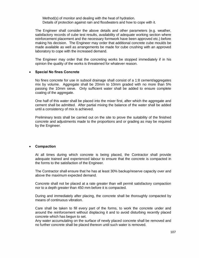
107
Method(s) of monitor and dealing with the heat of hydration. Details of protection against rain and floodwaters and how to cope with it. The Engineer shall consider the above details and other parameters (e.g. weather,
satisfactory records of cube test results, availability of adequate working section where reinforcement placement and the necessary formwork have been approved etc.) before making his decision. The Engineer may order that additional concrete cube moulds be made available as well as arrangements be made for cube crushing with an approved laboratory to cope with the increased demand.
The Engineer may order that the concreting works be stopped immediately if in his
opinion the quality of the works is threatened for whatever reason.
• Special No fines Concrete No fines concrete for use in subsoil drainage shall consist of a 1:8 cement/aggregates
mix by volume. Aggregate shall be 20mm to 10mm graded with no more than 5% passing the 10mm sieve. Only sufficient water shall be added to ensure complete coating of the aggregate.
One half of this water shall be placed into the mixer first, after which the aggregate and
cement shall be admitted. After partial mixing the balance of the water shall be added until a consistency of mix is achieved.
Preliminary tests shall be carried out on the site to prove the suitability of the finished
concrete and adjustments made to the proportions and or grading as may be required by the Engineer.
• Compaction At all times during which concrete is being placed, the Contractor shall provide
adequate trained and experienced labour to ensure that the concrete is compacted in the forms to the satisfaction of the Engineer.
The Contractor shall ensure that he has at least 30% backup/reserve capacity over and
above the maximum expected demand.
Concrete shall not be placed at a rate greater than will permit satisfactory compaction nor to a depth greater than 450 mm before it is compacted.
During and immediately after placing, the concrete shall be thoroughly compacted by
means of continuous vibration. Care shall be taken to fill every part of the forms, to work the concrete under and
around the reinforcement without displacing it and to avoid disturbing recently placed concrete which has begun to set.
Any water accumulating on the surface of newly placed concrete shall be removed and no further concrete shall be placed thereon until such water is removed.

108
Internal vibrators shall have a frequency of not less than 7,000 cycles per minute and
shall have a rotation eccentric weight of at least 0.75 kg with an eccentricity of not more than 15 mm. Such vibrators shall visibly affect the concrete within a radius of 250 mm from the vibrator.
Internal vibrators shall not be inserted between layers of reinforcement less than one and one half times the diameter of the vibrators apart. Contact between vibrators and reinforcement and vibrators and formwork shall be avoided.
Internal vibrators shall be inserted vertically into the concrete wherever possible at not
more than 500 mm centres and shall constantly be moved from place to place. No internal vibrator shall be permitted to remain in any one position for more than ten seconds and it shall be withdrawn very slowly from the concrete.
In consolidating each layer of concrete the vibrating head shall be allowed to penetrate
and revibrate the concrete in the upper portion of the underlying layer. In the area where newly placed concrete in each layer joins previously placed concrete, more than usual vibration shall be performed, the vibrator penetrating deeply at close intervals along these contacts. Layers of concrete shall not be placed until layers previously placed have been vibrated thoroughly as specified.
Vibrators shall not be used to move concrete from place to place in the formwork. At least one interval vibrator shall be operated for every four cubic meters of concrete
placed per hour and at least one spare vibrator for every three shall be maintained on Site in case of break down during concreting operations.
External formwork vibrators shall be of the high frequency low amplitude type applied
with the principal direction of vibration in the horizontal plane. They shall be attached directly to the forms at not more that 1.200 M centres.
In addition to internal and external vibration the upper surface of suspended floor slabs
shall be levelled with a tamping or vibrating screed prior to finishing. Vibrating elements shall be of the low frequency high amplitude type operating at a speed of not less than 3,000 r.p.m.
• Construction Joints
Construction joints shall be permitted only at the positions predetermined on the
drawings or as instructed on the Site by the Engineer. In general they shall be perpendicular to the lines of principal stresses and shall be located at points of minimum shear, viz. vertically at, or near, midspans of slabs, ribs and beams.
The position of construction joints, when not shown on the Drawings or otherwise
required by this specification, shall be decided on site having regard to the plant and labour made available by the Contractor for the manufacture, placing and compaction of the concrete as well as its curing, the climatic conditions prevailing at the time of concreting, the nature and size of the formwork and the conditions of operations of the work. The contractor shall submit his proposals to the Engineer for his approval before commencing the work.

109
Suspended concrete slabs are generally to be cast using alternate bay construction in bays not exceeding 15 m in length. No two adjacent bays are to be cast within a minimum period of 48 hours of each other. The joints between adjacent bays are to be in positions agreed with the Engineer.
Under no circumstances shall concrete be allowed to tailoff, but it shall be deposited
against stopping off boards. Before placing new concrete against concrete already hardened, the face of the old
concrete shall be thoroughly hacked, roughened and cleaned, and laitance and loose material removed therefrom, and immediately before placing the new concrete the surface shall be saturated with water and covered with a coat of mortar at least 25 mm in thickness composed of cement and fine aggregate in the proportions used in the concrete.
• Curing and Protection Care must be taken that no concrete is allowed to become prematurely dry and the
fresh concrete must be carefully protected within two hours of placing from rain, sun and wind by means of at least three layers of Hessian sacking, white polythene sheeting, or other approved means. This protective layer and the concrete itself must be kept continuously wet for at least seven days after the concrete has been placed. The Contractor must allow for the complete coverage of all fresh concrete for a period of 7 days. Hessian or white polythene sheeting shall be in the maximum widths obtainable and shall be secured against wind. The Contractor will not be permitted to use old cement bags, clear or any other colour polythene sheets, Hessian or other material in small pieces.
Concrete in foundations and other underground work shall be protected from admixture
with the falling earth after placing. Traffic or loading must not be allowed on the concrete until the concrete is sufficiently
matured, and in no case shall traffic or loading be of such magnitude as to cause deflection or other movement in the formwork or damage to the concrete members. Where directed by the Engineer props may be required to be left in position under slabs and other members for greater periods than those specified hereafter.
• Faulty Concrete
Any concrete which fails to comply with these Preambles, or which shows signs of
setting before it is placed shall be taken out and removed from the Site. Where concrete is found to be defective after it has set, the concrete shall be cut out and replaced in accordance with the Engineer's instructions. On no account shall any faulty, honeycombed, or otherwise defective concrete be repaired or patched until the Engineer has made an inspection and issued instructions for the repair.
On the Engineer's instruction, the contractor shall cut out and replace any concrete in any part of the structure if in the Engineer's opinion;

110
(a) The concrete does not conform to the specification, or (b) Deleterious materials or materials which are likely to produce harmful effects have
been included in the concrete, or (c) The honeycombed or damaged surfaces are too extensive, or (d) The finished concrete sizes are not in accordance with the drawings within
permissible tolerances, or (e) The settingout is incorrect, or (f) The steel cover has not been maintained, or (g) The protection, including curing of the concrete during the construction was
inadequate resulting in damage, or (h) Undue deformation of or damage to the works has taken place due to inadequate
shuttering or to premature traffic or to excessive loading, or (i) Any combination of the above points has taken place resulting in unsatisfactory
work. The whole of the cost, whatsoever (including time lost) which may be occasioned by
the need to remove faulty concrete shall be borne by the Contractor.
• Loading Tests The Engineer may direct that a loading test be made on the works or any part thereof if
he deems such a test to be necessary for one or more of the following reasons: (a) Failure of "Site cubes" to attain the strength requirements. (b) Premature removal of formwork; (c) Overloading of structure during construction; (d) Improper compaction of concrete;
(e) Any other circumstances attributable to alleged negligence on the part of the
Contractor which in the opinion of the Engineer may result in a structure being of less than the required strength.
If the loading test be ordered to be made solely or in part for reasons (a) to (d) the test
shall be made at the Contractor's own cost.

111
If the loading test be ordered to be made for reason (e), the Contractor shall be reimbursed for the cost of the test if the result is satisfactory.
Loading tests shall be carried out in accordance with the requirements of BS 8110. If the results of the test are not satisfactory, the Engineer will direct that the part of the
work concerned be taken down or removed and reconstructed to comply with the Specification or that such other remedial measures as he may think fit be taken to make the work acceptable and the Contractor shall carry out such work at his own cost.
The Engineer may also instruct the Contractor before a loading test takes place to take
out cylindrical core specimens from the structures concerned and have them tested. The cutting equipment and the method of doing the work shall be to the Engineer's approval. The specimens shall be dealt with in accordance with BS 1881. Prior to testing, the specimens shall be available for examination by the Engineer.
If the cores are ordered to be taken solely or in part for reasons (a) and (d) above, the
work involved and the testing shall be made at the Contractor's own cost. If the cores are to be taken for reasons (b), (c) and (e) above, the Contractor will be reimbursed the cost of the work involved and the testing if the loading test described in the previous paragraphs proves to be satisfactory.
No extensions of time shall be granted for any delays or disruption of work caused by
these tests.
• Steel Reinforcement The steel reinforcement shall comply with the latest requirements of the following
British Standards:
• Hot rolled MS for the • reinforcement of concrete BS 4449 • Hot rolled H.Y. steel for the • reinforcement of concrete BS 4449 • Cold worked H.Y. steel for the • reinforcement of concrete BS 4461 • Hard drawn steel wire BS 4482
Generally high yield, hirib rebars (425 & 460 N/mm²) shall be used for main reinforcement and mild steel round bars (250 N/mm²) for links and ductility for special elements where specified. In addition where so detailed, mild steel deformed bars shall also be used.
The Contractor shall submit a test certificate of the rollings. Reinforcements shall be
stored on racks above ground level in covered waterproof sheds to keep away rain water. The sheds shall be well drained to prevent deterioration or contamination from any cause. All reinforcement shall be free from loose mill scale or rust, grease, paint or other substances likely to reduce the bond between the steel and concrete.
• Fabric Reinforcement

112
Fabric reinforcement shall be electrically crosswelded steel wire mesh reinforcement to
BS 4483, and of the size and weight specified and made of wire to BS 4482.
• Fixing Steel Reinforcement Reinforcement shall be accurately bent to the shapes and dimensions shown on the
Drawings and Schedules and in accordance with BS 4466 and BS 8110. Reinforcement must be cut and bent cold and no welded joints will be permitted unless so detailed or directed by the Engineer.
Reinforcement shall be accurately placed in position as shown on the drawings, and
before and during concreting, shall be secured against displacement by using No. 18 S.W.G. annealed binding wire or suitable clips at intersections, and shall be supported by concrete or metal supports, spacers or metal hangers to ensure the correct position and cover. No part of binding wire shall protrude into the specified nominal cover.
No concreting shall be commenced until the Engineer has inspected the reinforcement
in position and until his approval has been obtained. The Contractor shall give two clear days' notice of his intention to concrete to the Engineer. Approval forms shall be submitted in duplicates. (A sample of the format of the Approval form is attached at the back of this specifications).
The Contractor is responsible for maintaining the reinforcement in its correct position,
according to the drawings, before and during concreting. During concreting a competent steel fixer must be in attendance on the concretors to adjust and correct the positions of any reinforcement which may be displaced. The vibrators are not to come into contact with the reinforcement.
Where required to support and retain the reinforcement in its correct position, the
Contractor shall provide templates, stools or other supports at his own cost. Unless permitted by the Engineer, welding of bar reinforcement at intersections or for
the joining of bars is prohibited. Where permission is granted, welding shall be carried out in accordance with the recommendations of the Institute of Welding for the welding of reinforcement bars.
The Contractor shall provide on-site facilities for cutting and bending reinforcement
whether he is ordering his reinforcement bent or not and shall ensure that a token amount of straight bar of each diameter is available on site for bending as and when directed by the Engineer in order that minor modifications may be implemented on site without prior notice.
Bar bending schedules shall be issued to the Contractor at least a month in advance of
the actual physical requirement on site. The Contractor is responsible for verifying that he has in his possession the required schedules to meet his programme and shall give the Engineer at least 3 weeks’ notice for any schedules that he requires.
• Splices and Screwed Couplers
Where specified in the works, splices and screwed couplers shall be CCL systems type or similar approved and shall be for reinforcement bar sizes 16, 20, 25 and 32.

113
The relevant certificates of performance shall be submitted to the Engineer for
approval. The Engineer may order additional relevant tests be carried out through the Contractor from time to time as a measure of continuous monitoring of quality and performance.
• Position and Correctness of Reinforcement
The Contractor shall draw the Engineer's attention in good time if any discrepancies
between details on drawings and bar bending schedules occur. Irrespective of whether any inspection and/or approval of the fixing of the reinforcement
has been carried out as above, it shall be the Contractor's sole responsibility to ensure that the reinforcement complies with the details on the drawings or bending schedules and is fixed exactly in position shown therein and in position to give prescribed cover.
The Contractor will be held entirely responsible for any failing or defect in any portion of
the reinforced concrete structure and including any consequent delay, claims, third party claims, etc., where it is shown that the reinforcement has been incorrectly positioned or is incorrect in size or quantity with respect to the detailed drawings or bending schedules.
• Spacer Blocks Spacing blocks of approved size and shape made of concrete similar to that used in the
surrounding construction and fixed to the reinforcement or formwork by No. 18 S.W.G. wires set into the spacer blocks or other approved means shall be provided where necessary to ensure that the requisite cover is obtained. The Contractor is to include for providing sufficient such spacer blocks in his prices for steel reinforcement where such supplier has been nominated. Where composite blocks or other forms of nib construction are used, spacer blocks are to be provided as shown on the drawings. These will generally consist of concrete blocks as described above made to fit the width of the rib less 3 mm to tolerance and with single or double grooves (depending on the number of the reinforcement bars used per rib) in the top surface with wire ties at each grove. The Engineer may direct that special types of spacers (e.g. preformed plastic types) be used in the whole or part of the works, if in his opinion the concrete spacers are not to the required standard.
• Nominal Concrete Cover to Reinforcement
Unless otherwise directed the nominal concrete cover to steel reinforcing bars
(including links and distribution) in any face shall be: Foundations against earth face 75 mm Foundation against blinding 50 mm Columns (main bars) 40 mm Beams (main bars) 30 mm or diameter of main bar.

114
Slabs and Stairs 20 mm Walls (main bars) 40 mm The tolerance on placing of bars to achieve nominal cover is +5mm
• Fixing Fabric Reinforcement The fabric shall be free from scale, rust, grease or other substances likely to reduce the
bond between the steel and the concrete and shall be laid with minimum 300 mm laps and bound with No. 18 S.W.G. annealed iron wire.
• Projecting Reinforcement Where reinforcement projects from a concreted section of the structure and this
reinforcement is expected to remain exposed for some time, it is to be coated with a cement grout to prevent rust staining on the finished concrete. This grout is to be brushed off the reinforcement prior to the continuation of concreting.
• Security Reinforcement
Spiral Spiral reinforcement where specified in the works shall be Chubb spiral, Agamas or
similar approved. It shall consist of steel bars of at least 15mm diameter forming a mattress with pitches not exceeding 125mm, and shall be delivered to the site in preformed 2 row mattress cages of exact and specified dimensions and incorporating appropriate spacer bars to maintain mattress rigidity. When assembled, the cages shall define the outline of the elements to be protected including allowance for openings. The assembling in the works shall be carried out under the supervision of the supplier's approved representative.
Twisted Plates These shall be chubb tangbars, John Tann bars, Tord bars or similar approved. They
shall be made from 3mm thick mild steel plates cut into strips running off a central cord. They shall be transported to the site in flat condition where they shall be twisted into spirals.
The twisting and laying of the units shall be carried out under the supervision of the
supplier's approved representative.
• Fixtures and Indentations in Concrete No openings, chases, holes or other voids shall be formed in the concrete without the
prior approval of the Engineer. Details of any fixtures to be permanently built into the concrete including the proposed positions of all conduits 25 mm and over in diameter

115
shall be submitted to the Engineer for his approval before being placed.
• Chases, Holes, etc. in Concrete The Contractor shall be responsible for the coordination with the Electrical and other
Subcontractors for incorporating electrical conduits, pipes, fixing blocks, chases, holes and the like in concrete members as required and must ensure that
adequate notice is given to such Subcontractors informing them when concreting members incorporating the above are to be poured. The Contractor shall submit full details of these items to the Engineer for approval before the work is put in hand. All fixing blocks, chases, holes, etc., to be left in the concrete shall be accurately set out and cast with the concrete.
• Position of Electrical Conduits
Unless otherwise instructed by the Engineer all electrical conduits to be positioned
within the reinforced concrete shall be fixed inside the steel cages of beams and between the top and bottom steel layers in slabs and similar members.
The proposed position of all conduits 25 mm and over in diameter which are to be
enclosed in the concrete shall be shown accurately on a plan to be submitted to the Engineer, whose approval shall be obtained before any such conduit is placed.
• Formwork
The method and system of formwork which the Contractor proposes to use shall be
approved by the Engineer before construction commences. Formwork shall be substantially and rigidly constructed of timber, steel, plastic, precast concrete or other approved material.
All timber for formwork shall be good, sound, clean, sawn, well seasoned timber free
from warps and loose knots and of scantlings sufficiently strong for their purpose.
• Construction of Formwork All formwork shall be of sufficient thickness and with joints close enough to prevent
undue leakage of liquid from the concrete and fixed to proper alignment, level and plumb and supported on sufficiently strong bearers, shores, braces, plates, etc. properly held together by bolts or other fastenings to prevent displacement, vibration or movement by the weight of materials, men and plant on same and so wedged and clamped as to permit easing and removal of the formwork without jarring the concrete. Where formwork is supported on previously constructed portions of the reinforced concrete structural frame, the Contractor shall by consultation with the Engineer ensure that the supporting concrete structure is capable of carrying the load and/or sufficiently propped from lower floors or portions of the frame to permit the load to be temporarily carried during construction.
Soffits for beams and slabs of spans greater than 10m shall be erected with an upward
camber of 5 mm for each 3.0 m of horizontal span or as directed by the Engineer, without reducing the depth of the element.

116
Great care shall be taken to make and maintain all joints in the formwork as tight as
possible, to prevent the leakage of grout during vibration. All faulty joints shall be cuddled to the Engineer's approval before concreting. The formwork shall be sufficiently rigid to ensure that no distortion or bulging occurs
under the effects of vibration. If at any time the formwork is insufficiently rigid or in any way defective the Contractor shall strengthen or improve such formwork as the Engineer may direct.
The Contractor's attention is drawn to the various surface textures and applied finishes
required and the faces of formwork next to the concrete must be of such material and construction and be sufficiently true to provide a concrete surface which will in each particular case permit the specified surface treatment or applied finish.
All surfaces which will be in contact with concrete shall be oiled or greased to prevent
adhesion of mortar. Oil or grease shall be of a nonstinging mineral type applied as a thin film before the reinforcement is placed. Surplus moisture shall be removed from the forms prior to placing of the concrete. Great care shall be taken to avoid oiling or greasing the reinforcement.
Temporary openings shall be provided at the base of columns, wall and beam forms
and at any other points where necessary to facilitate cleaning and inspection immediately before the pouring of concrete. Before the concrete is placed the shuttering shall be trued up and any water accumulated therein shall be removed. All sawdust, chips, nails and other debris shall be washed out or otherwise removed from within the formwork. The reinforcement shall then be inspected for accuracy of fixing. Immediately before placing the concrete the formwork shall be well wetted and inspection openings shall be closed. Cement slurry shall be applied to previously casted concrete as necessary to allow for adequate bonding. The erection, easing, striking and removing of all formwork must be done under the personal supervision of a competent foreman, and any damage occurring through faulty formwork or its incorrect removal shall be made good by the Contractor at his own expense.
After removal of formwork, all projections, fins, etc., on the concrete surface shall be
chipped off, and made good to the requirements of the Engineer. Any voids or honeycombing shall be treated as described under "Faulty concrete".
• Stripping Formwork All formwork shall be removed without undue vibration or shock and without damage to
the concrete. No formwork shall be removed without the prior consent of the Engineer. The Contractor shall notify the Engineer of his intended removal of any formwork at least two days in advance. The minimum periods that shall elapse between the placing of the concrete and the striking of the formwork will be as follows:
Beam sides, wall and columns (unloaded) 24 hours Slab soffits (props left under) 3 days

117
Beam soffits (props left under) 7 days
Removal of props to: (partly subject to 7 days concrete cube strength being Satisfactory) Slabs 10 days Beams 14 days Cantilever beams and slabs 28 days In continuous spanning slabs or beams, no span shall be depropped until the adjoining
spans have been cast and cured for the specified periods. Stripping and repropping will not be permitted. The striking times indicated herein are
for normal conditions and shall be adjusted if: (a) The span of the structural member under consideration exceeds 6.0m for beam.
An additional period of one day for each 500mm of additional span shall then be allowed.
(b) The dead load of the structural member under consideration forms a large
proportion of the total design load. (c) The setting of the concrete has been retarded for any reason. (d) Any combination of the above points and other considerations which would call for
such a precaution to be taken. In any case, props shall be left in place in the lower two consecutive floors over which
construction loads are expected to be supported.
• SURFACE FINISHES
• Fair Face Finish Where fair face finish is specified the concrete shall be brought to a perfectly true
smooth and even surface by rubbing with carborundum stone dipped in cement grout. Such work must be commenced within one hour of removing the formwork and be actively and rapidly pursued until completed, the object being to complete the finish as soon as possible after the removal of the shuttering. On no account may such work be postponed to a later stage in the Contract. Fair face surfaces shall be clean, smooth, even true to form and free from all board marks, joint marks, honeycombing, pitting etc. The Contractor is permitted at his own expense to provide smooth lining to the forms which will achieve the required finish without rubbing down. All rubbed down work must be lightly washed with plain cold water at the completion of the Contract, and not before the cement grout used in the finish is at least four weeks old after initial mixing.
• Wrought Lined Formwork

118
The shuttering shall be constructed of wrought tongued and grooved boarding, plywood or blackboard lined with approved laminated plastic sheeting to produce a concrete surface with truly flat surface completely free from all air bubbles, joint marks, honeycomb and other pittances and blemishes to the approval of the Engineer.
Should the Contractor desire to use alternative materials he should submit his
proposals to the Engineer for approval. Should the Contractor fail to obtain approval and the Engineer subsequently rejects
the work, the Contractor will at his own expense carry out all work necessary to attain the approval of the same.
• Tamped Finish
Areas so specified shall be finished at the time of casting with a tamped finish to the
Engineer's approval produced by an edge board. Board marks are to be made to a true pattern and will generally be at right angles to the traffic flow. Haphazard or diagonal tamping will not be accepted.
• Board Marked Finish
Where so directed or measured the finish shall be that of a board marked pattern
panels, the boards shall be arranged vertically and of widths and sizes all as detailed on the drawings. All exposed concrete will be left unpainted and therefore every care and attention shall be paid to obtain a satisfactory visual appearance and that maintenance of the same throughout the building operation. The finished surfaces shall be free from blow holes, hungry patches and other blemishes, and a sample panel is to be provided and approved by the Engineer before work commences.
Unless otherwise specified, the formwork shall be rip sawn softwood to the
Engineer's approval and shall have a sufficiently strong grain to impart a corresponding pattern on the concrete surface. Unless otherwise approved it shall have four uses only and shall be carefully cleaned from adhering grout after each use. It shall be lightly oiled with an approved nonstinging mould oil.
• Vertical Ribbed Finish
Unless otherwise specified, vertical ribbed finish to walls shall comprise 50 x 50 mm
concrete projections at 450 mm centres cast vertically on the face of wall. All surfaces are to be as described under "Wrought Formwork".
• Diagonal Ribbed Finish
Unless otherwise specified, diagonal ribbed finish to walls shall comprise 50 x 25 mm
deep concrete projections at 100 mm centres cast at 45 degree angle to the vertical on face of wall. All surfaces are to be as described under "Wrought Formwork".
• Chisel Dressed Finish
Where specified a chisel dressed finish is to be carried out on any grade of concrete

119
but not until it is at least 30 days old. The surfaces are to be fully chisel dressed to remove a maximum of 12 mm (average 9 mm) of the surface to expose the aggregate without excessive cracking or breaking thereof.
Where the drawings show details of arises of columns, beams, etc. these are to be
preformed with timber fillets set in the formwork, and care must be taken in working up to those to preserve a clean line. For vertical surfaces of walls and columns, particular care must be taken to remove all sharp projections. For beam soffits this requirement is not necessary.
All chisel dressed surfaces are to have the margins chisel dressed by hand for a
minimum width of 75 mm commencing from the fillet edge. Thereafter mechanical chisel dressing may be used but the Contractor must ensure that a uniform texture and even plan surface is achieved. The use of pointed steel tools for both hand and mechanical chisel dressing is essential. Upon completion the surfaces are to be thoroughly wire brushed and washed down and protected during the course of construction from damage, dirt, cement grout, etc.
• Precast Concrete
• General
Unless otherwise approved by the Engineer, all precast concrete construction shall be
carried out on the Site and shall conform to requirements given elsewhere in these preambles.
The maximum size of coarse aggregate in precast concrete shall not exceed 20 mm
except for thicknesses less than 75 mm where it shall not exceed 10 mm. The compacting of precast concrete shall conform with requirements given elsewhere
in these preambles except for thin slabs where use of immersion type vibrators is not practicable. The concrete in these slabs may be consolidated on a vibrating table or by any other methods approved by the Engineer.
Steam curing of precast concrete will be permitted. The procedure for steam curing
shall be subject to the approval of the Engineer. The precast work shall be made under cover and shall remain under the same for
seven days. During this period and for a further seven days the concrete shall be shielded by sacking or other approved materials kept constantly wet. It shall then be stacked in the open for at least a further seven days to season before being set in position. Where steam curing is used these times may be reduced subject to the approval of the Engineer.
Precast concrete units shall be constructed in individual forms. The method of handling
the precast concrete units after casting, during curing and during transport and erection shall be subject to the approval of the Engineer, providing that such approval shall not relieve the Contractor of responsibility for damage to precast concrete units resulting from careless handling.
Repair of damage to the precast concrete units, except for minor abrasions of the

120
edges which will not impair the installation and/or appearance of the units will not be permitted and the damaged units shall be replaced by the Contractor at his own expense.
Except where precast work is described as "fair face" or as having "exposed
aggregate" or terrazzo finish the moulds shall be made of suitable strong sawn timber true in form to the shapes required. Unless otherwise described faces are to be left rough from the sawn moulds.
Where precast work is described as "fair face" the moulds are to be made of metal or
are to have metal or plywood linings or are to be other approved moulds which will produce a smooth dense fair face to the finished concrete suitable to receive a painted finish direct and free from all shutter marks, holes, pittances, etc. In his prices for such precast work the Contractor shall include for all rubbing down to produce the finish required, to the satisfaction and approval of Engineer. Where precast work is to have an "exposed aggregate" or terrazzo finish the moulds shall be constructed to the requirements given for moulds for "finished fair" work. The method of achieving the exposed aggregate finish shall be "aggregate transfer" or other approved method.
• Precast Concrete Cladding Units
These shall be cast to the general details shown on the drawings. The contractor shall submit working/shop drawings for each type of the cladding panels to the Engineer for approval before he commences casting operations. The panels shall be cast in special yards and shall be cured adequately before being hoisted into position in the structure, taking care that no parts are broken in the process. The units shall then be joined together with Insitu concrete and flexibly connected to the top and bottom beams to allow for limited movement of the combined unit. The precast units shall be installed to the lines, grades and dimensions shown on the Drawings or as directed by the Engineer.
• Hollow Block Suspended Construction (Composite Floor Slab)
Concrete hollow blocks for use in the composite floor slabs shall be of the standard sizes required or as shown on the drawings and are to be of adequate strength to support the concrete during placing and consolidation by vibration. Blocks are to be manufactured in accordance with the procedure specified in BS 6073 and to be of a mix not weaker than 1:4:8 cement: sand: stone using maximum 10 mm size aggregate.
Concrete blocks are to be cured for at least 28 days before use on the Site. During the first
seven days of curing, blocks are to be kept permanently damp and protected from exposure to sun and wind.
Concrete blocks are to be well wetted before the pouring of cement. Hollow clay filler blocks for use in the composite floor slabs are to be of the sizes shown
on the drawing and to be of adequate strength to support the concrete during placing and consolidation by vibration. They shall be obtained from an approved manufacturer. Before any orders are placed, at least 6 sample clay blocks shall be provided for the

121
approval of the Engineer. Any clay blocks subsequently delivered to Site which in the opinion of the engineer are not of equal standard to the approved samples shall be rejected.
Rejected blocks shall immediately be removed from the Site and shall not be used in
the works. Clay blocks are to be full cured before delivery or use on site. Clay blocks are to be well wetted before pouring of concrete.
• Composite Floor Construction
The hollow block floor construction is generally to be as shown on the Engineer’s Drawings. Care shall be taken in placing blocks to ensure that they are set out in accordance with the details shown on the Drawings and that they run truly in line without encroaching on the width of the in-situ ribs.
The open ends of hollow blocks, if adjacent to concrete to be place Insitu, are to be plugged or stopped to prevent the concrete from flowing into the void and the Contractor is to include for this in prices. The Contractor should note that slip tiles are not to be used to the soffits or ribs and he is to take this into consideration in pricing the items of formwork to the soffit of hollow block floor construction. Before concreting is carried out the blocks are to be thoroughly wetted. Caret should be taken during concreting that the width of ribs between the rows of blocks and the solid Insitu concrete shown on the Drawings adjacent to supporting beams is not encroached upon by the blocks. It is essential that the concrete topping be poured at the same time as the ribs between hollow blocks. Reinforcement shall be positioned accurately with required cover in accordance with the Drawings and using the particular spacing blocks with wire ties as previously described. Spacer blocks shall be provided in ribs at not more than 1.2 m centres. Care must be taken during concreting that the reinforcement is not displaced. Where holes or services, occur, the necessary holes or pockets shall be accommodated by the replacing of a hollow block by in-situ concrete or the widening of a rib all in accordance with the Engineer’s instructions. Prices for such holes through hollow block construction are to include the re-arrangement or substitution of the hollow block with solid concrete in addition to the actual formation of the hole. • Concrete Surface Beds
Before placing concrete and where specified or shown on the Drawings a layer of the

122
appropriate gauge polythene or diothene sheeting shall be laid on the blinding above the hard core filling. Minimum 300 mm laps shall be provided at all joints.
The concrete shall be placed as soon as possible after being mixed. In transporting the
concrete, adequate precautions shall be taken to avoid damage to the prepared base. The concreting shall be spread to such a thickness that when compacted it shall have the finished thickness as specified or shown on the Drawings. A layer of concrete 25 mm less than the finished thickness shall first be spread and struck off at the correct level to receive the top fabric reinforcement.
The top layer shall then be added. Not more than 30 minutes shall elapse between
spreading the bottom layer and the start of compaction of the top layer. The Contractor shall be responsible for maintaining the reinforcement in its correct position during the placing and compaction of the concrete.
The compaction and finishing of the concrete shall be effected by immersion vibrators
and a hand or mechanical tamper weighing not less than 10 Kg per meter run and having a tamping edge shod with a steel strip 75 mm wide fixed to a tamper by countersunk screws. Immersion vibrator with "spade" attachments will be permitted. Compaction shall be continued until a dense, scaled surface finish is achieved. Over compaction causing an excessive amount of fines to be brought to the surface shall be avoided.
The surface of the concrete shall be finished to the surface texture specified to the
levels, falls and cross falls, as directed or shown on the Drawings and shall be subject to the following tolerances:
The level shall be within + or 6 mm of the levels specified.
The falls shall be within 10% of the falls specified.
The smoothness shall be such that departures from a 3m straight edge laid in any direction shall not exceed 3mm.
Minor irregularities shall be made good by the use of a steel float but in no circumstances
shall mortar be used to make good the surface.
As soon as the surface has been finished, it shall be protected against too rapid drying by
means of damp Hessian, white polythene sheeting or other approved means placed carefully on the surface and kept damp and in position for 7 days and the concrete shall be kept wet for a further 21 days. The most critical period is the first 48 hours after placing and curing during that time shall be very thorough.
The Contractor is to obtain the Engineer's approval to the material and method he
proposes to use for curing and no concreting will be permitted until sufficient such material is on Site.

123
Forms shall not be removed from freshly placed concrete until it is at least 24 hours old.
Care shall be taken that in their removal no damage is done to the concrete, but should any damage occur the Contractor shall be responsible for making it good.
• Expansion Joints in Concrete Surface Beds
Expansion joints shall be positioned and constructed as shown on the drawings. The
joints in the surface beds shall be absolutely square and true to line and position.
All joints in surface beds shall be formed to the patterns and shapes to coincide exactly with the joints in the surface finish or as otherwise indicated on the drawings. Formwork shall be manufactured from steel of heavy angle section and be to the Engineer's approval. The Contractor shall submit drawings of the forms he intends to use and obtain the Engineer's approval before fabrication. Panels shall be poured in alternate bays as agreed with the Engineer. No construction joints other than those indicated on the Drawings shall be submitted.
• Notes Concerning Measurement and Pricing
The Contractor must allow for all costs incurred during the progress of the Contract for
complying with the provisions concerning the preparation and use of "Designed mixes" and "weigh batchers" for all structural concrete work.
Absolutely no deviation from the use of "Design mixes and weigh batching machines
shall be entertained on the basis of site topography expanse or any other reason whatsoever as the Contractor will have been deemed to have allowed for these in his pricing.
Prices for concrete shall include for mixing and depositing as described or indicated
and for hoisting and depositing at the various levels required throughout the building, and shall also include for forming or hacking a satisfactory key for all faces receiving asphalt and plaster work. Prices for slab shall also include for levelling off the surface as described under "Compaction", and all temporary formwork to form construction joints at bay edges.
• S T R U C T U R A L S T E E L W O R K
• GENERAL

124
Steel portal frames, trusses and purlins will be carried out by an Approved Specialist Sub-Contractor.
• QUALITY OF MATERIALS AND WORKMANSHIP
The quality of all materials and workmanship used in the execution of the Works shall in any case comply with the requirements of current relevant British Standards and Codes of Practice, including all the latest requirements.
• MATERIALS
All materials shall be of the best quality, free from defects. The materials in all stages of transportation, handling and stacking shall be kept clean and injury from breaking, bending and distortion prevented.
• WORKMANSHIP
All work shall be carried out in the most workmanlike manner and strictly as directed by the Engineer.
Welding shall be neatly cleaned off and units shall be pre-fabricated in the workshop wherever possible, the minimum of site welding being employed.
All screwed work shall have full internal and external threads and holes shall have been cleaned off. Countersinking’s must be concentric.
• TESTS
The Engineer may at any time require any materials to be tested in accordance with the requirements of the Standards listed above. The cost of all successful tests shall be borne by the Client. The Contractor shall, if required by the Engineer, promptly supply at his own expense test pieces. The cost of tests on materials failing to comply with this standard shall be borne by the Sub-Contractor. If in the opinion of the Engineer, faulty material and/or workmanship has been used in the Works, the Sub-Contractor may be directed to dismantle and cut out the parts concerned and remove them for examination and testing. The cost of dismantling, cutting out and making good to the approval of the Engineer shall be borne by the Sub-Contractor.
• FABRICATION
The Standard of works and the general procedure to be followed during fabrication shall be in accordance with B.S. 449. The Sub-Contractor must submit all his shop drawings to the Engineer for checking and approval and must also ascertain all dimensions on the Site prior to commencement of fabrication.
• RELEVANT BRITISH STANDARDS B.S. 4360 Weldable Structural Steels B.S. 449 The use of Structural Steel in Building

125
B.S. 4848 Hot Rolled Structural Steel Sections B.S. 2994 Cold Rolled Steel Sections B.S. 1775 Steel Tubes for Mechanical, Structural and General Engineering purposes B.S. 5135 Metal arc welding of Carbon and Carbon Manganese Steels B.S. 639 Covered Electrodes for the manual metal arc Welding of
Carbon and Carbon Manganese Steels B.S. 4872 Approval testing of welders when welding procedure is not required.
B.S. 916 Black bolts, screws and nuts, or alternatively; B.S. 3692 ISO metric precision hexagon bolts, screws and nuts B.S. 4190 ISO metric black hexagon bolts, screws and nuts B.S. 3410 Metal black hexagon bolts screws and nuts B.S. 4320 Metal washers for general engineering purposes B.S. 4395 High-strength friction grip bolts and associated nuts and washers for Structural Engineering B.S. 5493 Protective Coating of Iron and Steel Structures against corrosion B.S. 15 Mild steel for general structural purposes B.S. 4 p.2 Hot rolled Hollow Sections B.S. 994 Cold Rolled Steel Sections B.S. 938 General requirements for the Metal Arc Welding of structural steel tubes to B.S. 1775 B.S. 1856 Covered Electrodes for the Metal Arc Welding of Mild Steel.

126
• CUTTING AND BENDING
All members, plates, brackets, etc., shall be neatly and accurately sheared, sawn, or profiled to the required shape as shown on the Drawings. Where steel is oxy-cut to shape, care shall be taken to preserve the full finished sizes required.
If members or plates are bent or set, the bends or sets shall be correctly made to the radii or angles specified without leaving hammer marks. The material may be heated to permit this. Material that has been heated shall be annealed to approval.
• PUNCHING AND DRILLING
Holes for black bolts shall be drilled or punched 2 mm larger in diameter than the bolt size. Holes for high tensile friction grip bolts shall be drilled or sub-punched and reamed to 2 mm larger in diameter than the specified bolt size. All drilled holes shall be parallel-sided and shall be drilled with the axis of the holes perpendicular to the surface. Badly drilled holes shall be reamed out to approval and larger bolts fixed. All rough arises shall be ground off. Holes formed or enlarged by oxy-cutting will not be accepted and must be filled to approval by electric welding and re-drilling.
• BOLTING
All bolts used shall be of such length that at least one full thread is exposed beyond the nut after the nut has been tightened. Where a nut or bolthead would bear on an inclined surface, a bevelled washer of the correct shape shall be interposed between the two surfaces. Bevelled washers shall not be allowed to get out of position during fabrication and erection and for this purpose may be spot-welded to the steel surface. Bevelled washers for use with high tensile bolts shall not be welded.
• BLACK BOLTS, NUTS AND WASHERS
Black bolts shall comply with the requirements of B.S. 916 (B.S.W. threads) or B.S. 4190 (ISO metric threads).
• CLOSE TOLERANCE BOLTS
Close tolerance bolts shall conform to B.S. 3692
• HIGH TENSILE BOLTS High tensile bolts shall conform to B.S. 1768 (UNCE and UNF threads)
• HIGH TENSILE BOLTS High strength friction grip bolts shall be : (a) In accordance with B.S. 4295 (b) Samples of load indicating bolts must be submitted to the Engineer for approval.
• RAWLBOLTS

127
Samples of rawlbolts shall be similarly submitted to the Engineer to approval.
• WASHERS (a) Plain and tapered washers to B.S. 3410 or B.S. 4320 (b) Washers for high strength friction grip bolts shall be appropriate to the type and quality of the bolt specified.
• RIVETS
The steel used for rivets shall be in accordance with B.S. 4360 and in the case of high tensile steel rivets shall be so manufactured that they can be driven and the heads formed and the physical properties not impaired.
• NAILS AND SCREWS
Nails and screws shall be of best quality mild steel of lengths and weight approved by the Engineer. Nails shall be to B.S. 1202.
• ELECTRIC WELDING
All welding shall be carried out in strict accordance with the requirements of B.S. 5135 and electrodes shall comply with B.S. 639.
Fusion faces shall be free from irregularities such as tears, fins, etc., which would interfere with the deposition of weld metal.
Fusion faces shall be smooth and uniform and shall be free from loose scale, slag, rust, grease, paint and other deleterious material.
All welds shall be of approved type and finished size as specified. Welding shall be carried out in such sequence that minimum distortion of the parts welded results.
Preparation of edges for welding shall be carried out by planning or machine flame cutting. Manual flame cutting will not be permitted.
Parts to be welded shall be maintained in their correct relative positions during welding, preferably by jigs.
Multiple-run welds shall be carried out with each run closely following the previous run but allowing sufficient time for the proper removal of slag. The Sub-Contractor shall ensure that each run is inspected and any satisfactory weld cut out and remade to approval.
Welds in material 25 mm or greater in thickness shall be made by the Argon arc or similar approval process, and special precautions shall be taken to prevent weld cracking.
Unless otherwise specified, the minimum size of fillet shall be 6 mm.

128
On completion, welds shall present a smooth and regular finish. Weld metal shall be solid throughout with complete fusion between weld metal and parent metal and between successive runs throughout the joint.
Defects shall be cut out and made good to approval in sound weld metal. The external faces of butt welds are to be ground smooth on completion.
• ROLLED SECTIONS All shop connections shall be electric welded or bolted with high tensile bolts.
No bolts used shall be less than 12 mm diameter and no weld less than 40 mm in length. At least two bolts shall be used in connections transmitting loads, unless otherwise indicated by the Engineer.
No weld of less than four times the nominal fillet size shall be deemed capable of carrying load.
Beam to column connection not detailed shall be of "standard" top and bottom cleat connections with the load carried on the bottom cleat. "Standard" web connections shall be used for connecting beams to beams.
Field connections shall be as detailed, i.e. bolted with high tensile or black bolts in drilled holes. Black bolts in punched holes will only be permitted for connections carrying a designed load or connections to timber members.
• STRUCTURAL HOLLOW SECTIONS
Hollow sections shall be connected by electric welding unless 54 and Appendix C of B.S. 449.
Butt welds in tension members will not be permitted unless the prior approval of the Engineer in writing has been obtained.
Butt welds where permitted, shall be made with the fusion surface of the ends of each member properly prepared and the member properly aligned.
• ASSEMBLY
• TRUSSES AND PORTAL FRAMES
Trusses and portal frames shall be carefully set out to the dimensions shown on the drawing and cross checked with actual site setting out.
Where it is required that trusses be cambered, such camber shall be provided by bending the bottom chord to an arch or a circle.
Notwithstanding any dimensioned spacing of purlin cleats, the Sub-Contractor shall ensure

129
that purlin cleat spacing is satisfactory for the available stock lengths of roof sheeting. However, the Engineer's approval must first be obtained before any alteration is made in purlin spacing or sheeting sizes.
Splices in portal and other frames shall be made where shown on the details or where directed by the Engineer.
• BOXED MEMBERS
Abutting edges of boxed members shall be connected and sealed with a continuous weld to exclude the entrance of moisture. Where specified such welds shall be ground flush to approval.
• SHOP ASSEMBLY
Assembly of units in the shop prior to transportation to the site must be inspected by the Engineer before painting. The assembled work shall be laid out in the shop or yard such that all parts are accessible for inspection and testing.
The Sub-Contractor shall furnish all facilities for inspection and testing of the works and he must notify the Engineer on every occasion materials are ready for inspection.
• MARKING
All members of the structure to be site-assembled shall be marked in accordance with the shop details marking plans submitted to the Engineer for approval.
• ERECTION
• SITE DIMENSIONS
Erection shall not commence unless and until accurate site dimensions have been taken by the Sub-Contractor. No claims will be considered should site dimensions differ from those on the Drawings. Any modifications to the structural steel required in order to comply with site dimensions shall be made on the ground to the Engineer's approval before erection commenced.
• SAFETY
All erection shall be carried out by competent and experienced personnel and the Sub-Contractor shall take every care to safeguard members of the public, workmen, and adjoining property against injury and/or damage. The Sub-Contractor shall be held responsible for all damage caused to the structure, workmen, or other property during erection.
All gear used shall be of adequate strength and shall comply with all current Regulations.
During erection the work shall at all times be adequately bolted, guyed and/or braced to make the structure secure.

130
• STORAGE AND HANDLING
Steel members shall be stored, handled and erected in such a manner that no member shall be subjected to excessive stresses which could have an adverse effect on the properties of the steel. If, in the opinion of the Engineer, the steelwork has been subjected to such treatment, the Sub-Contractor shall remove the member from the site and replace it at his own expense.
• ERECTION NOTES
No member or part of a member which has been bent or distorted shall be erected in that condition. All straightening shall be done on the ground.
Stanchions shall be wedged to line and level on steel or cast from wedges and checked by the Engineer. After acceptance, stanchion bases shall be grouted to approval before wedges are removed. Unless otherwise shown on the Drawings, all stanchions shall be left truly vertical and correct to line and level. Beams, girders, etc., shall be erected level unless otherwise shown, and correctly positioned.
Trusses and open web joints shall be carefully handled at all times and during erection shall be lifted at such points and in such a manner as will preclude any possibility of damage from excessive stresses.
Packing plates, shims, washers or similar adjusting pieces found necessary to accommodate tolerance in structural site dimensions shall be provided and fixed to the approval of the Engineer.
Immediately after erection, each truss shall be made secure by purlins, bracing or guys to approval of the Engineer.
Bracing shall be fixed in position as soon as dependent portion of the work is completed.
• TIGHTENING AND TESTING HIGH TENSILE FRICTION GRIP BOLTS
Before assembly, the contact surface, including those adjacent to the washers, shall be descaled, and be free from dirt, oil, loose scale, burrs, paint (except priming paint), pits and other defects that would prevent proper seating of the parts.
Bolts shall be fixed with approved hardened flat or tapered washers as required between the bolthead and nut and the softer mild steel.
When bearing faces of the bolted parts have a slope of more than 1 in 20 with respect to a plane normal to the bolt axis, square smooth bevelled washers shall be used to compensate for lack of parallelism.
All bolts shall be tightened by the "Turn of Nut" method. This method shall generally be as specified in B.S. 3249 and as approved by the Engineer to achieve in all bolts a minimum tension equal to the proof load.

131
• GROUTING
Unless otherwise detailed on the Drawings, a space of not less than 40 mm shall be provided undersides of column baseplates and footings, and between all beams and roof truss bearings and concrete pads.
After each column, beam or roof truss has been wedged up to a line and level and fixed in position to approval, the space between footing and pad and the underside of the one base-plate or steel member shall be grouted by the Main Contractor with 1:1 Cement: Sand mortar.
The Portland cement and sand shall be thoroughly mixed together with sufficient water to produce a mixture or "damp earth" consistency and shall be used within twenty minutes of mixing. The caulking mixtures shall be packed tight into the space between baseplate and foundation and protected from damage until it sets.
• PAINTING
• PAINTS All paints are to be obtained from a Supplier approved in writing by the Engineer.
Paints are to be delivered to the Site or to the Contractor's fabrication site in the original containers as supplied by the manufacturer, with seals unbroken, and are to be used in strict accordance with the manufacturer's instructions.
Manufacturer's representatives are to be free to visit the Site and inspect materials for laboratory analysis. Paints are not to be thinned unless instructed by the Engineer. No external painting is to be carried out during rain or when rain is likely to occur before the paint has had time to dry. All surfaces are to be dry and free from moisture during painting.
• PREPARATION FOR PAINTING
All structural steel shall be thoroughly scraped and wire-brushed to remove mill scale and rust. Dirt, grease and oil shall be washed off with white spirit and the steel allowed to dry.
• APPLICATION
A first coat of an approved primer shall be applied after fabrication of the works has been completed. A minimum of 24 hours shall elapse before the steel is moved from its position after painting.
After delivery to Site, the steel shall be carefully examined and all areas where the priming coat has been damaged and/or where rust has developed shall be washed white spirit and wire brushed as necessary and a further priming coat as for the first coat applied to completely cover the damaged areas.
During erection, surface of steel which are to be in contact shall be painted with one further coat of primer as previously described and the surfaced brought together whilst the paint is

132
still wet.
After erection, a second coat of an approved primer and a third coat of micaceous iron oxide shall be applied. Welds shall not be painted over until they have been deslagged, inspected and approved.
Steel purlins and side rails shall generally be painted as for steelwork except for purling and rails supporting aluminium sheeting, when the following specification shall be used:
Prime Coat - Red oxide sonc chromate primer, or red lead graphite, or other approved primer. Finishing Coat - As specified by the Architect/Engineer
The interior of mild steel gutters shall be prepared as previously described and painted with 2 coats of Robbialac Epilac Coal Tar Epoxy Paint, or other approved paint.
• PRICES MEASUREMENT AND PAYMENT
Prices quoted by the Sub-Contractor shall be based on the calculated weights of steel, and shall include for shop drawings, manufacture, painting, and supply, all as specified and as shown on the Drawings, including the cost of delivery to the Site or other agreed place or places and the supply of bolts, rivets, plugs, gussets, cleats, to complete the erection of the works. Prices shall include for erection, (all labour, scaffolding and other erection equipment necessary) and cover the cost of additional prime coat painting as previously specified. The prices shall also include for lining up, levelling and plumbing, and grouting up of the bases. The basis for payment for steelwork shall be calculated steel weights of the structure. Any variation in design which result in either a net increase or decrease in steel weight from the quoted amount in excess of 25% shall result in the appropriate additions or deductions to the agreed quotation. Any written instructions from the Engineer which may result in additional work over and above that for which the Contractor quoted will be considered as extras and shall be paid for in the basis of calculated additional steel weights.

133
RAINWATER GOODS
• GENERAL
Rainwater goods shall be in accordance with particular Specification and as shown on the Drawings and as per the direction of the Engineer. Rainwater gutter and pipes shall be made out of steel sheets of the required thickness.
• PVC RAINWATER PIPES
The Contractor shall supply and fix heavy-duty grey PVC pipe and fittings as indicated on the drawings and schedules. Pipes and fittings shall be in accordance with relevant B.S. including B.S. 4514 and fixed to the manufacturer’s instructions and B.S. 5572. The rain water pipes system shall incorporate synthetic rubber gaskets as provided by the manufacturers whose fixing instructions shall be strictly adhered to. Suitable supporting brackets and pipe clips shall be provided at maximum of one metre centres. The Contractor shall be responsible for the joint into the Gully Trap/Rain water grits on Drain as indicated on the drawings.
• PIPE SUPPORTS
This Sub-Clause deals with pipe supports securing pipes to the structure of buildings for above ground application. The variety and type of supports shall be kept to a minimum and their design shall as such as to facilitate quick and secure fixing to metal, concrete, masonry or wood. Consideration shall be given when designing supports, to the maintenance of desired pipe falls and the restraining or pipe movement to a longitudinal axial direction only. The Contractor shall supply and install all steelwork forming part of the pipe support assemblies and shall be responsible for making good any damage to builders work associated with the pipe support installation. The Contractor shall submit all his proposals for pipe supports to the Engineer for approval before any erection work commences. The Contractor shall allow for priming and painting of the exposed rain water down pipes to approval.
• FIXING
Sheeting and rainwater goods shall have fixings generally in accordance with B.S. 1494. Rainwater gutter, pipes, etc., shall be fixed properly with necessary accessories to avoid

134
any leakage of rainwater.
Asbestos-cement sheeting shall be fixed in accordance with the manufacturer’s instructions, to leave a perfectly water-tight roof.
• INTRODUCTION
Profiled steel sheeting shall be used in these buildings if approved non-corrosive ad guaranteed coating has been applied on internal surfaces of the sheeting.
• RIDGE OF THE ROOF
The ridge capping is constituted of purpose-made fibre-cement sheets. These sheets are placed with the same transversal overlapping as the roof sheets and with the corresponding vertical spacing as well.
• PIPE PENETRATIONS
The penetrations of the roof by pipes are carried out by means of :
• Flashings sheets • Box housing
Covered by a cowl corresponding to the diameter and the number of pipes.
The flashing sheets and the box housing are to be placed on bearer battens, and shall have the same transversal and lateral overlapping as the folded sheets and shall be fixed in the same way.
Water tightness between the cowl and the pipes is to be achieved by packing with tarred yarn and filling up with sealant mastic.
• PURLINS SUPPORTING THE ASBESTOS SHEETS
The purlins shall be made of steel profiles.
It is compulsory that the purlins be stabilized by anti-sag bars for spans over 3m.
Both the purlins and the attachment of these and their supports shall be calculated in the compliance with the British Standards and the loads defined earlier.
• SHEETING WITH PROFILED STEEL SHEETS
Sheeting consisting of profiled steel sheets pre-painted on the outer side shall be resistant to the climate and shall be coated with corrosion resistant material. The sheets shall be galvanized or factory-preprinted on both sides with a zinc covering of 400 g/s.m. or corrosive resistant material respectively on each side, in accordance with the British Standard or DIN concerning galvanized steel plates/sheets.
135
The design of the profiled steel sheets and the fastening of the profiled steel sheets for cladding and roof shall be to British Standards and the loads as described before. Screws shall be supplied with coloured head and shall be according to the supplier’s specifications. Wherever possible standard solutions shall be carried out. Where two different elements of the construction are joined, notably the details between roofs and the machine tower, there shall be windproof and water-tight overlapping.
• INTERLOCKING CONCRETE TILES
Interlocking concrete roof tiles and ridges shall have integral colouring and shall be obtained from an approved source and otherwise to approved samples and colours, and shall be laid strictly in accordance with the manufacturer’s printed instructions.

136
• WALLING • STANDARDS
A. The requirements of the following British Standards and Codes of Practice shall be observed:-
BRITISH STANDARD B. Bricks and blocks of fired brickwork clay or shale B.S. 3921 Part 2 C. Concrete bricks and fixing bricks B.S. 1180 D. Shapes and dimensions of special bricks B.S. 4729 E. Precast concrete blocks (for general use and load bearing B.S. 2028 walls above damp proof course) B.S. 1364 Type B F. Precast concrete blocks (for internal B.S. 2028 non-load bearing walls) B.S. 1364 Type C G. Sand for mortar for plain and B.S. 1200 Table 1 reinforced brickwork, block walling and masonry and Table 2 H. Building lines (Hydrated line) B.S. 890 Part 2 J. Ready mixed lime: sand for mortar B.S. 4771 K. Mortar plastioizers B.S. 4887 L. Methods of testing mortars and Specification for mortar testing sand B.S. 4551 M. Materials for damp proof courses B.S. 743 N. Milled sheet lead and strip for building purposes B.S. 1178 O. Metal ties for cavity wall construction (vertical twist type) B.S. 1243 Fig. 1 CODES OF PRACTICE P. Structural recommendations for load bearing walls C.P. 111 Q. Walling C.P. 121 Part 1 R. Masonry - rubble walls C.P.121, 202 Part 1 S. Walls and partitions of blocks and slabs C.P. 122 T. NOTE : The Contractor's attention is drawn to Section `G' of the Standard Method of measurement. U. WATER shall be as specified in "Concretework".

137
V. CEMENT shall be as specified in "Concretework".
SAND shall be as specified in “Concretework”.
Lime shall be hydrates limes for cement/lime mortars and comply with B.S. 890, semi-hydraulic class “B” calcium limes.
Concrete Blocks shall be solid or hollow blocks to comply with the relevant standard as previously mentioned and shall be solid hard, true to size and shape and sharp arrises and in accordance with Ministry of Works, Standard Specification for Metric sized concrete blocks for walling dated September, 1972.
All concrete block walling indicated as load bearing shall have a minimum average crushing strength of 3.5 or 7.0 newtons per square millimetre or as otherwise specified in Particular Specification.
They shall be obtained from an approved manufacturer or manufactured on site in approved block making machines. The mix used shall not be less than (1:9) by volume and maximum size of aggregate shall be 12 mm size. The blocks on removal from the machine shall be laid on edge or racks under sheds erected by the Contractor and left for 3 days during which period they shall be kept constantly wet.
After this initial period they shall be placed on edge in the open racks and protected by sacking or other approved covering and kept wet for a further 5 days.
Thereafter the blocks shall be left in the same position without wetting for a further 20 days. No blocks shall be used in the Works until 28 days old and until samples have been tested and approved by the Engineer.
The Contractor shall ensure that the blocks are stocked separately in their respective categories in the structure in the position shown on the Drawings.
Stone for Walling shall be good hard local stone equal in Standard and quality to “Nairobi Blue Stone”. Stone shall be squared, butchered or smooth dressed and joints chisel dressed on the face. Masonry work to receive render shall be so dressed as to reduce dubbing-out to a minimum.
The coursed stone shall not be less than 150 mm deep and 305 mm long. All stone shall be laid on its natural or quarry bed lines.

138
Gauged mortar shall be used for walling and shall be composed of the part Portland Cement to two parts hydrated lime and nine parts sand (1:2:9) measured in gauge boxes thoroughly mixed dry preferably with an approved mixing platform with water added afterwards until all parts are completely incorporated and brought to a proper consistency and used within the hour.
No partially or wholly set mortar will be allowed to be re-used or re-mixed.
All stone shall be wetted before laying and the top of walling where left off, shall be wetted before re-commencing building, walls to be kept wet 3 days after building.
All blocks and walling to be kept true, plumb and level with all perpends vertical and in lime and work shall not rise more than three courses above the adjoining work and all such rising are to be properly racked back.
The Contractor must provide proper setting out or storey rods so that all work is coursed to cills, lintels and underside of beams thus reducing horizontal cutting to a minimum.
All walling must be carefully bounded together so that no vertical joint in any one course is nearer than 100 mm from the joint in the course above or below.
All walling must be bedded in solid mortar with cross joints will flushed up at each course as the work proceeds.
J. To walls less than 190 mm thick the reinforcement shall consist of gauge 24 “Expament” wall reinforcement horizontally in bed joints every alternate course and lapped over “expament” from column where abutting same.
K. Rates for walling are to include for reinforcement strips.
• LABOURS ON STONE WALLING
Labours stated in the Standard Method of Measurement as to be included shall be deemed to include for redressing the beds of stones on site to the minimum extent necessary to obtain uniformity of coursing and for any redressing of faces necessary to bring the thickness within the tolerance specified. Where described as fair face, the stones shall be of approved colours and chisel or machine dressed to provide the required finish to the Architect’s approval. They shall be built to equal or varying courses with neat, flush or recessed joints to an approved sample.

139
Rates for walling of any description are to include for all expenses in connection with the provision and conveyance of samples of walling materials to the Ministry of Works or other approved Materials Testing Laboratory.
• EXPANSION JOINTS
Filler materials shall be Flexcell as manufactured by Expandite Ltd., or equal and approved. Sealers shall be plastic or sealastic or equal and approved applied in accordance with the Manufacturer’s instructions.
• BRICK FACEWORK
Brick facework shall be to the thickness shown on the Drawings or otherwise specified. The bricks shall be obtained from Kenya Clay Ltd. or such other source(s) approved by the Architect and they shall be hard and true to shape, including overburns (if so required) to give a variation in colour. They shall be laid on a mortar bed with straight horizontal joints and true perpends and shall be firmly anchored to the walls using wall ties. The ties must be galvanised metal of suitable strength and girth, twisted to a figure ‘8’ and built into walling and facing; the walling and facing being set to leave a reasonable gap (say 5 mm) to minimise afflourescence. Colour washing will not be permitted unless approved by the Architect.
• ASPHALT WORK
A. The requirements of the following British Standards shall be observed:- BRITISH STANDARD B. Mastic asphalt for tanking and damp proof B.S. 1162, 1410 courses (Natural rock asphalt aggregate) and 1418 C. Mastic asphalt for tanking and damp proof B.S. 988, 1097 courses (Limestone aggregate) CODES OF PRACTICE D. Protection of buildings against water from ground C.P. 101 E. NOTE: The Contractor’s attention is drawn to Section “J” of the Standard Method of Measurement. F. All asphalt shall comply with the requirements of subsections B.S. 1418 and 1097 and P.C. 102 specifically dealing with tanking operations.
G. For tanking to basement lay over the whole area of the basement concrete floor
horizontal damp proof course in three thickness laid with 150 mm laps to a total thickness of 30 mm and carried through walls and to outer edge of top course of foundations outer face of wall to cement with vertical damp proof course with a double angle fillet.
140
H. Vertical face of basement walls shall then be covered with damp proof course applied in three thickness with 75 mm laps total thickness of not less than 20 mm.
J. Vertical damp proof course shall be carried up to covered height of 150 mm above ground level and connected at bottom to horizontal damp proof course in walls with double fillet formed on top of foundations to form a complete tank to basement.
K. All junctions between horizontal and vertical asphalt shall be warmed, cleaned and properly made good with two-coat angle fillets at all integral angles.
L. Properly made good joints between lining pits and horizontal damp proof course to floor shall be effected and double angle fillets to all internal angles maintained.
A. It is essential that continuity of tanking be maintained. Care must be exercised to see
that such continuity is not destroyed by stanchions, pits, sumps etc. A. Protect asphalt by the application of loading coats immediately each section of Work is
completed. Pumping of any water gaining access shall be continued until not only the asphalt work is complete, but also until loading coasts are thoroughly set.
A. If the water level is near such water level shall be maintained at not less than 0.3m below
the level of the base concrete during the progress of tanking work to avoid the application of asphalt on wet surfaces and this pumping operation shall be maintained until the temporary sump has filled and sealed.
A. Roofing Asphalt
Roofing asphalt shall be mastic asphalt to B.S. 988/1988, Table 3 column 111 and shall be laid by a specialist sub-contractor to be approved by the Architect and to the requirements of C.P. 144.
The asphalt shall be laid in two coats to a thickness not less than 20 mm on a black sheathing felt to B.S. 747 : Part 2 Type 4A (I) weighing not less than 17 Kg. Per 25 m roll and shall be finished with aluminium bituminous paint to the Architect’s approval. The contractor’s rates shall include for complying with all these requirements.
A. Roofing Tiles
Roofing tiles shall be a shown on the drawings and/or measured in the Bills of Quantities and shall be form a source approved by the Architect. The tiles shall be laid strictly in accordance with the manufacturer’s instructions so as to keep the roof truly watertight.

141
• ROOFING: BITUMINOUS FELT ROOFING
• GENERAL
All work shall be executed by a firm approved by the Architect in writing. The Sub-Contractor shall obtain from the Contractor a statement in writing to the effect that the screed is dry, clean and satisfactory before the coverings of fest are laid. A copy of the statement is to be forwarded to the Architect. The Contractor shall obtain form the approved Sub-Contractor for felt roofing work a written guarantee and undertaking that a period of a twelve calendar month from and after the certified date of completion of the whole of the works such Sub-Contractor shall at his own expenses make good to the satisfaction of the Architect all and any defects in the felt roofing work which shall be attributable to improper materials or faulty workmanship and shall bear the cost of any consequential damage to the structure.
• WORKMANSHIP
All surfaces to receive felt are to be cleaned before and as the work proceeds. All work shall be laid to falls without hollows or loose patches.
• BITUMEN FELT ROOFING
Built up roofing felt shall be “Cabro” coloured fibre-based mineral surfaced felt complying with B.S. 747, part 2, supplied by Messrs Cassman Brown & Company Ltd., P.O. Box 18072, Nairobi. The bottom layer shall be type 2C self-finished as asbestos weighing not less than 13 Kg. Per 10 S.M., the intermediate layer type 1C self finished bitumen felt of similar weight and the top layer type 1E mineral surfaced felt weighing not less than 36 Kg. Per S.M. The primer shall be “Cut back” bitumen solution of suitable viscosity and the bonding compound shall be oxidised or “blown” bitumen melted and applied hot. Nails shall be galvanised, extra large head, felt nails complying with B.S. 1202 Type IV G.
All roof work shall be laid with a number of layers of felt as described, to a maximum thickness of 3/8” (10 mm) lapped across falls with minimum laps of 2” (50 mm) at edges and 3” (75 mm) at end of sheets, full hot bonded either by pouring and rolling or mopping with bitumen bonding compound laid an even thickness using 13 Kg. Bitumen per square metre of roofing substructure and between layers, with successive layers of felt laid breaking joint.
Cement surface shall be primed before receiving bonding compound. All adjoining work shall be protected from damage due to laying and all stains shall be removed and made good.

142
• QUARRY TILING
Quarry tiles shall be size 200 x 200 x 22 mm thick and shall be obtained from an approved manufacturer. They shall be laid square on one layer or roofing felt or as specified and be jointed in cement mortar (1:4), the joints being kept as fine as possible.
• CHIPPINGS
Mineral aggregate chippings shall be approved hard, angular light coloured stone chippings to pass a 10 mm sieve and be retained on a 6 mm sieve. These shall be laid as soon the roof is clear of other trades. They shall be closely bedded at a rate of 16 Kg/S.M. on a hot bitumen dressing compound, and all loose chippings removed.
• PROTECTION
The roof shall be protected against damage by following trades and in no circumstances shall the roofing be used as a building platform, for storage of materials, for mixing concrete and/or heating materials. All roofing and adjacent work shall be left clean.

143
• FLAT ROOF WATER PROOFING WITH EPDM RUBBER
• SPECIFICATION OF WATERPROOFING MATERIAL The water proofing materials shall consist of a single ply HERTALAN EPDM RUBBER, shall not be less than 1.2mm thick and shall have the properties specified below (unless otherwise agreed at the time of award of the contract). The membrane material shall be supplied by the manufacturers in sheets (or rolls) large enough to minimize jointing which shall be capable of forming single bends in situ. At the points where the membrane goes over parapet, proper care shall be taken to seal the edges per manufacturer’s specifications, including chiselling grooves to tuck in the rubber. Before fixing the waterproofing membrane, the substrate must be smooth, clean, dry, and free of oil/fat, sharp edges and foreign materials. All bituminous waterproofing materials previously used must be removed in total and carted away. The membrane shall be adhered to the substrate at least 50% using an adhesive specified by the manufacturer. The rubber surfaces shall be painted with two coats of rubberized pain as manufactured by Crown Paints, to give a grey finish or any other colour that may be specified. Areas as specified in the drawings, prone to mechanical damage shall be protected by installing paving tiles. The application of waterproofing membrane shall be carried out by a specialist sub-contractor who is to be specifically approved by the architect and will be required to give a TEN YEARS GUARANTEE against workmanship backed by a similar guarantee for materials from the MANUFACTURERS. Such a SUB-CONTRACTOR will have had a demonstrable experience in installing such materials in East Africa.
Property Test or Requirement Demonstration
a) Thickness/uniformity BS903 Part A38 In the range of +3% to 5% stated thickness. b) Tensile strength and BS 2782 Method Minimum Tensile Strength at Elongation 210A break 4kN/m
Minimum elongation at break 350% c) Tear Strength BS 903 Part A3 Minimum tear strength 8N/mm d) Thermal expansion Change of dimension at 100 degrees centigrade Maximum +1%

144
e) Resistance to aging and DIN 7864 Heat aging Tensile strength maximum Weathering at 80 degrees change on (b) above after 28 days
20% Elongation at break, maximum change on (b) above after 28 days 20%.
f) Deterioration by lime DIN 7864 Tensile strength, maximum Change on (b) above after 28 days 20% Elongation at Break. g) Ozone resistance BS 903 Part A4 No visible cracking under 7 x Magnification after being exposed under strain to the standard ozone rich atmosphere h) Robustness Contractor to The material must be sufficiently provide evidence for robust to be suitable for similar work installation on the basis foreseen in the contract. i) Bio-degration Contractor to provide The material shall be immune evidence for similar work to bacterial attack for installed conditions at the site. j) Chemical Resistance Contractor to provide Good resistance to corroding features of supply material substances with which the material may come in contact in installed conditions at the site.

145
• VANDEX PRODUCTS
• SPECIFICATION FOR WATERPROOFING CONCRETE STRUCTURES
• Remedial Work: All areas shall be examined for structural defects. Shrinkage cracks exceeding 0.3mm (0.01”) in width shall be cut or chiselled out at least 10mm wide and 15mm deep and washed out. Then a slurry coat of Vandex Super shall be applied. Following this the groove is filled with a mixture of 3 to 1 sand and cement in stiff mortar consistency.
Over-poured forms, around columns and/or inverted beams, form groves shall be cleaned out, rinsed with water and slurry coated with Vandex Super. These grooves shall then be filled flush with a mixture of 3 to 1 sand and cement. Any honeycombed concrete found in walls and/or inverted beams/columns shall be raked out to solid concrete, washed out with water, coated with a slurry coat of Vandex Super and filled out flush with a 3 to1 mixture of sand and cement.
• Cleaning Concrete surfaces must be free from all form scale, laitance, algae growth, mould, oil, curing agents and any other foreign materials. The finish of the surfaces shall be a brush finish. All laitance (cement scum) shall be removed as soon after pouring as possible.
• Pre watering Concrete shall be thoroughly wetted down in order to achieve the penetration of the activated chemicals and thereby starting the crystalline growth throughout the capillary tracts. All free lying water must be removed from surface, leaving the concrete in a damp condition just prior to Vandex application.
• Mixing Vandex Super is mixed to slurry consistency. Add approximately 0.8 parts water to 2.00 parts powder or 9 liters to 25 Kg when mixing full bags, and mix thoroughly until the mixture is free from lumps.
• Application The pre-watered concrete surface shall receive two coats of Vandex Super coat approximately 0.75 Kg/sq.m. Use a Vandex brush and work the material well into the surfaces.

146
The application should be as even as possible trying to avoid thick and thin spots. Areas applied too thick will not cure right and when drying cracks and subsequently peeling may form. The second coat may be applied when the first coat has set and is not drawn off by the second coat.
• Curing and protection Vandex applications must be protected against sun and rain. After the application is dry to the touch, cover with polyethylene sheet (hessian cloth) or wet sand for five days. If this is not possible, sprinkle with water several times a day for five days. Do not apply Vandex materials at temperature below 5 degrees C or on supercoiled structures.
• Additional Information When concrete is poured in sections, it is recommended that each section is keyed. After keyed form is removed and just prior to pouring the next section the construction joint shall receive a slurry coat of Vandex Super (1.5 Kg/sq.m). This does not apply to control or expansion joints.

147
• CARPENTRY, JOINERY AND IRONMONGERY
• GENERALLY
All timber for permanent work in the buildings shall, before use, be approved by the Architect for quality in accordance with the foregoing specification for its respective grade.
All Carpenter's work shall be left with sawn surface unless particularly specified to be wrot. Scantlings and boarding shall be accurately sawn and shall be uniform in width and thickness throughout. All Carpenter's work shall be accurately set out and in strict accordance with the Drawings and shall be framed together and securely fixed in the best possible manner with properly made joints. Provide all brads, nails, screws, bolts, etc., as necessary. Nails shall comply with BS 1202 and bolts with BS 916.
Variations from specified dimensions of scantlings shall not exceed the tolerance stated in the aforementioned Grading Rules. Board 1" thick or less shall hold up to the specified sizes. All timber shall be as long as possible and practicable to eliminate joints.
Sizes and thickness of wrot carpentry and joinery are nominal that is to say 3 mm reduction off specified sizes will be allowed for each wrot face, except where described as finished sized in which case no reduction from the stated thickness or size will be permitted.
Ends of timbers required to be built into walls shall have 12 mm air space between same and walling.
All joiner's work shall be wrot unless otherwise described.
All mouldings shall be accurately run and finished and all arrises shall be slightly rounded. Framed work shall be cut out, properly tenoned, shouldering, etc., and framed together as soon after the commencement of the Works as is practicable but should not be wedged up until required for fixing in position and any portions that warp, get in winding, develop shakes or other defects shall be replaced with new.
As soon as required for fixing in position the framing shall be glued together with best quality glue and properly wedged or pinned etc., as described.
Unless otherwise described oval or round brads will be used for fixing all face work, all heads shall be properly punched in. Where described as pelleted work screws shall be countersunk and the screw heads covered with timber pellets to match the adjacent timber.
All plugs employed as fixings for joinery, etc., unless otherwise stated shall be "philplug" or other equal and approved, filled into holes of a suitable size. The holes shall be drilled with special masonry drills and not cut with a cold chisel and hammer. Under no circumstances will wooden plugs be permitted. The expression "plugged" shall be taken to mean fixed with and including plugs as last described to stone or concrete. Timber to be left for polishing shall be specially selected and approved and have adjacent places matched and uniform or symmetrical in colour and grain. All fixed joinery which is liable to become bruised or damaged in any way shall be properly cased and protected by the Contractor until the completion of the Works.

148
Should any of the Carpenter's or Joiner's work shrink, warp, wind or develop any other defects within six months after the completion of the Works, the same shall be removed and new fixed in its place together with all other work which may be affected thereby, all at the Contractor's cost and expense.
• QUALITY OF TIMBER
The qualities of timber stated herein are those named and described in "The Export of Timber Rules, 1964".
All timber described as "Sawn Cypress" shall be Grade II (select grade) sawn cypress.
All timber described as "wrot cypress" is to be approved Grade I (Prime Grade) wrot cypress.
All timber described as "wrot cedar" is to be Grade I (Prime Grade) wrot cedar. All timber described as "wrot hardwood" shall be First Grade Hardwood.
No joinery work is to be put in hand until the Architect has seen and approved the colour and grain of the timber to be employed.
All the above timbers when used for Carpenter's work are to be well seasoned to a moisture content not exceeding 20% of their dry weight. When used for Joiner's work they are to be kiln seasoned or air dried and when delivered to site shall have a moisture content not exceeding 15% of their dry weight.
All timber for permanent work in the building shall before use, be approved by the Architect for quality in accordance with the foregoing specification for its respective grade. Any timber not so approved is to be removed from the Site immediately. Where practicable, timbers shall be in one length to eliminate joints.
All timber is to be clearly marked to denote grade.
• PRESERVATIVE TREATMENT
All Structural timber employed in Carpentry Work or where otherwise specified is to be celcurized to a retention of 0.4 lbs. of dry salt per cubic foot of timber. Any cut ends are to be painted with the appropriate solution to leave no untreated surfaces.
Timber so treated must have been reduced to the required moisture content before being incorporated in the works.
149
• PRIMING WOODWORK
All woodwork which is to be painted or hidden from view and the bottoms and tops of all doors and the backs of all frames are to be primed before fixing. Priming shall be touched up from time to time during the progress of the work.
• SITE DIMENSIONS
Before putting in hand any joinery work, whether to be built in with the carcass or fixed later the Joiner is to ascertain and check all dimensions on the Site which affect or govern Joinery Work.
• SCRIBING
All mouldings, frames and any other Joinery work shall be accurately scribed to fit the contour of any irregular surface against which they abut either at ends or longitudinally.
• PLYWOOD
The plywood shall generally conform to the requirements of BS 1455 and shall be Grade 2 Bonding INT. Where described as external quality it shall be Grade 2 Bonding M.R.
• BLOCKBOARD
Where blockboard is specified, it is to be in accordance with BS 3444, of the thickness specified and absolutely solid and glued throughout.
• VENEERS
All veneers to be specially selected for grain and colouring and no veneered work shall be put in hand until the Architect has approved grain and colour.
• HARDWOOD
Hardwood shall be as specified on the Drawings or otherwise measured or other equal and approved suitable for painting in accordance with BS 1142 and shall be prepared and fixed strictly in accordance with the manufacturer's instructions.
• LAMINATED PLASTIC SHEETS
Laminated plastic sheets are to be as specified on the Drawing or otherwise measured in the Bills, or other equal and approved, of a colour to be selected by the Architect.
• FLUSH DOORS
Flush doors in general are to be of the thickness stated complying with BS 459 Part 2A; hollow, semi-solid or solid cored, interior or exterior quality as required and veneered as described. All flush doors shall be faced with 4 mm plywood or 3 mm MDF, as specified, both sides on ex 25 mm horizontal internal construction at 50 mm centres with 2 No. 10 mm round vent holes throughout top to bottom and in addition are to have 10mm hardwood

150
lipping all round morticed and glued into framing. Styles, top and bottom rails to be ex 50 x 75mm with an additional ex 50 x 75 mm intermediate rail 150 mm below top of the door and 225mm above the bottom of the door. Lock blocks are to be on both sides of door and to be 150 x 300 mm. Samples of flush doors are to be submitted to the Architect for his approval before bulk orders are placed.
• OTHER DOORS
All doors (except flush doors) are to have tenoned ends covered by a cover strip of matching timber with grain running with and matching that of the door and is to be glued sunk screwed and pelleted in position.
• IRONMONGERY
The Contractor is to order and to check consignments of Ironmongery upon receipt and store them in safe keeping until required for fixing.
All ironmongery shall be fitted and fixed in the best possible manner. Rates for fixing are to include for all cutting, sinking, boring, mortising and fitting in hardwood or softwood and for supplying all necessary and matching screws. Rates for door furniture shall also include for fixing before painting, removal during painting operations and afterwards refixing and for labelling all keys with door references and handing to the Architect upon completion. Two keys will be provided for each lock and the Contractor is to allow in his rates for a master key system to all Departments except the Staff Houses, including supplying master keys.
All locks, springs, and other items of ironmongery with movable parts shall be properly tested, cleaned, properly lubricated with graphite and adjusted where necessary and left in perfect working order upon completion of the works by the Contractor who shall include for this in his prices for fixing.

151
• METAL WORK
• GENERAL
All materials shall be the best of their respective kinds and all work carried out as directed by the Architect.
Mild steel shall be of approved manufacture complying with the requirements of BS 15. Screws, bolts, washers, etc. to comply with BS 1916 and 1494.
Welds to be neatly executed, filled smooth and left clean. Aluminium sections shall comply with the requirements of BS 1161, with surface finishes to the Architect's approval.
Metal windows and doors shall be supplied by a sub-contractor, approved by the Engineer after documentations have been submitted.
Considerable care shall be taken in the transportation, handling and storing of the metal windows and doors and in their protection from damage after they are fixed in position.
The windows and doors shall be pointed all round with Evomastic Dutyl 37 or other equal and approved caulking mastic applied with an approved caulking gun. A temporary hardboard slip shall be fixed all round both sides of the windows prior to plastering or rendering in order to provide a gap for this pointing.
• PARTITIONS, GENERALLY
Lightweight or demountable partitions shall be as shown on the Drawings and/or measured in these Bills of Quantities.
Aluminium Partitions
Aluminium framework, where specified, shall be anodised or powder coated to approved samples and shall comply with the relevant BS Standards.
Drywall Partitions Where specified, partitions shall be Drywall Pelican Systems comprising drywall studs and gypsum boards. The studs shall be cut to lengths and spaced as specified by the manufacturer or in accordance with the Architects’ Drawings. They shall be jointed together with stud connectors to produce a rigid system and shall be covered with gypsum boards and/or glazed as shown on the Drawings or otherwise directed. Joints in the gypsum boards shall be covered with paper tape and flushed over with jointing compound, ready for decoration as specified elsewhere in these Preambles.
Rates for drywall studs shall include for cutting to required lengths, stud connectors, rigid angles, edges and the like, drilling, screws and waste. Rates for boards shall similarly include cutting to size, drilling, fixing and waste.

152
• FLOOR, WALL AND CEILING FINISHING
• GENERAL
The whole of the plasterwork and other wall, floor and ceiling finishings shall be executed to the entire satisfaction of the Architect and any work rejected shall be taken down and re-executed by the Contractor at his own expense. All scaffolding, temporary rules and screeds, tools or special appliances required shall be furnished by the Contractor.
• CEMENT
Shall comply with the requirements of BS 12.
• LIME
The lime shall comply with BS 890. Class A, non-hydraulic, and shall be run to a putty in a pit dug on site or in an approved container. Water is first to be run in and the lime added until it is completely submerged. It shall be kept submerged and stirred vigorously until all lumps are disintegrated. The resulting lime putty shall then be run through a fine sieve and placed in another container and kept clean and moist for not less than eight weeks before use.
• SAND
Sand shall comply with the requirements of BS 1199 graded in conformity with Table 1 hereof.
• “BELZONA” CLEAR CLADDING
“Belzona” Clear Cladding (Local agents: Molecular Maintenance Ltd., P.O. Box 18208, Nairobi) shall be used strictly in accordance with the Manufacturer’s printed instructions and in the areas specified by the Architect.
• “BOMANITE” PAVING
“Bomanite” Paving is a proprietary finish available from and done by “Bomanite“ (Kenya) Ltd., P.O. Box 41103, Nairobi and from whom further information may be obtained. Where specified or otherwise directed, this material shall be used strictly in accordance with the manufacturer’s printed instructions.
• “ECLIPSE” FLOOR FINISH
Where specified, “Eclipse” floor finish shall be used strictly in accordance with the manufacturer’s printed instructions. This product is obtainable from Thika Works Ltd., of P.O. Box 30185, Nairobi

153
• PAVINGS GENERALLY
Surfaces to be paved shall be wire-brushed, well wetted and pointed with a cement and sand (1:1) grout before any paving is applied.
All pavings shall be laid with joints coinciding with the construction joints in concrete beds on which they are laid and the pattern set out accordingly and they shall be kept continually damp for seven days before application during which period no traffic will be permitted over them.
• POLISHED COLOURED CEMENT AND SAND PAVING
Cement and sand shall be composed of one part cement to one part sand to three parts of 1/4" to 1/8" gauge black trap grit, applied in one operation to the thickness shown on the drawings. The contractor shall allow for lightly polishing the finished surface perfectly smooth and hard with a steel trowel and dead level or to true falls if so described. It is most important that the polishing is not overdone, that neither water nor dry cement is added during this operation and that no trowel marks nor rough areas are left.
Cement and sand pavings shall be coloured by the admixture of "Cementone" or other equal and approved colouring pigment for the full thickness of the paving and skirtings. A sample of the required tint shall be approved by the Architect before work commences and all pavings shall thereafter comply in every respect with the approved sample. Finishes shall be machine polished to a fine even surface free from voids or pits. Surfaces shall first be washed clean and rough polished and all holes, etc., filled in with an approved filler and left for a 24-hour period. Finally the work shall be washed down and given a final polish to the texture approved by the Architect.
• POLISHED GRANOLITHIC OR TERRAZZO PAVING
Granolithic paving shall be composed of one part of cement to two parts of approved colour stone chippings (Nairobi black trap or other approved) graded from 6 mm downwards and with a maximum of 10% of stone dust laid to the thickness required in bays separated by approved black plastic strips. No bay shall exceed 7 square meters and the pattern is to be approved by the Architect before work commences. The paving is to well rolled and left to cure thoroughly before polishing commences.
Polishing is to be executed by machine and the surface of the paving is to be polished to a fine even surface free from voids or pits.
Polished Granolithic or Terrazzo paving is to be executed by an approved Sub-Contractor.

154
• WASHED GRANOLITHIC PAVING
Washed granolithic paving shall be mixed and laid as described for polished granolithic or terrazzo paving but the surface is to be lightly brushed with a stiff broom after the initial set has taken place and well washed with clean water to expose the aggregate.
• IRONITE PAVING
Ironite paving shall be size graded iron particles as produces by the Ironite Co. Ltd., local agents: Pearson Ltd., Nairobi. The paving shall be laid strictly in accordance with the manufacturer’s instructions using the “three layer construction” method having the top or third layer consisting of 0.5” Ironite laid whilst the screed base is still wet. The topping for heavy duty floor shall consist of the following measured by volume:
1 part Ironite. 4 parts washed concrete sand passing 3/16” screen and passing 100 mesh screen. 4 parts granite chips, graded through 1/4” sieve and retained on 1/8” sieve. 4 parts cement. 4 lbs. ironite per square yard 1/2” thickness.
• FLEXIBLE P.V.C. FLOOR TILING
Flexible P.V.C. floor tiling shall be carried out by an approved specialist and shall consist of tiles in accordance with BS 3261, of approved manufacture and colour and to the sizes and thickness indicated in the Drawings or otherwise specified.
The tiles shall be laid to the patterns as indicated (If any) on the drawings with close butt joints and bedded in approved mastic on a clean, dry cement and sand (1:3) screed as before described with a steel trowel finish.
On completion, any surplus mastic which may have squeezed out of the joints shall be removed, the tiles cleaned with an approved cleaner, and two coats of approved P.V.C. tile sealer applied.
• PARQUETRY FLOORING
Parquetry flooring and adhesive shall both be to the Architect’s approval and a sample panel shall be required before commencing this work.
• WOOD BLOCK FLOORING
Woodblock flooring shall be to the thickness shown on the drawings or otherwise specified and shall be laid with an approved adhesive. They shall be laid herringbone or basket weave pattern and properly tamped, sanded and polished to approval.
• WOODWOOL SLABS
Are to be unreinforced 50 mm thick of standard metric sizes and obtained from National Timber and Hardware Syndicate, P.O. Box 41438, Nairobi or other approved supplier.
155
• PLASTERING AND RENDERING GENERALLY
All surfaces to be plastered or rendered shall be brushed clean and be well wetted before plaster is applied. All plaster and rendering shall be kept continuously damp for seven days after application. All arrises shall be finished true and slightly rounded except where otherwise stated, and shall be run at the same time as the adjoining plaster. No partially or wholly set plaster or rendering will be allowed to be used or re-mixed.
The Contractor shall prepare samples of the plastering and rendering as directed until the quality, texture and finish required is obtained and approved by the Architect after which all plastering executed in the work shall conform to the respective approved samples.
The Contractor shall cut out and make good all cracks, blisters, and other defects and leave the whole of the work perfect on completion. When making good defects, the plaster or rendering shall be cut out to a rectangular key, and all finished flush with face of surrounding plaster or rendering.
Rates for plastering and rendering are to include for raking out joints of walling or hacking concrete to form a key. Instead of hacking the Contractor will be permitted to treat concrete surfaces, at his own expense, with bonding fluid such as "Plastaweld" manufactured by I. Manager & Son Ltd., or other equal and approved, applied in strict accordance with the manufacturer's printed instructions.
• INTERNAL PLASTER
Internal plaster is to be two coat plaster not less than 12 mm thick where the base or scratch coat shall be of one part cement to six parts sand and the finishing coat of lime putty to which has been added 10% by volume of cement prior to application. The surface is to be finished true and level with a wood float.
• BAGGED FINISH
Bagged finish surfaces are to be treated with a complete covering of 1:4 liquid cement/sand wash thoroughly rubbed in to cavities with a sack.
• TYROLEAN RENDERING
Tyrolean rendering shall be in two coats. The coat shall be 10mm. thick and consist of a mixture of 93.5 lb. of cement with 10% lime added by volume and four cubic feet of sharp sand applied direct by means of trowel and brought to a level finish with a straight board or rule. No dubbing or scratching is necessary and it is inadvisable to use a float since the surface of this coat should be kept as open as possible. When a rule is used care must be taken to see that it is used in all directions and not in one only, otherwise ridges may be left which show through the Tyrolean finish. The finishing coat shall be applied by means of a Tyrolean spraying machine and shall consist of white "Concrete" and sand and shall be ascertained by trial. Only sufficient shall be mixed as can be used in one hour.
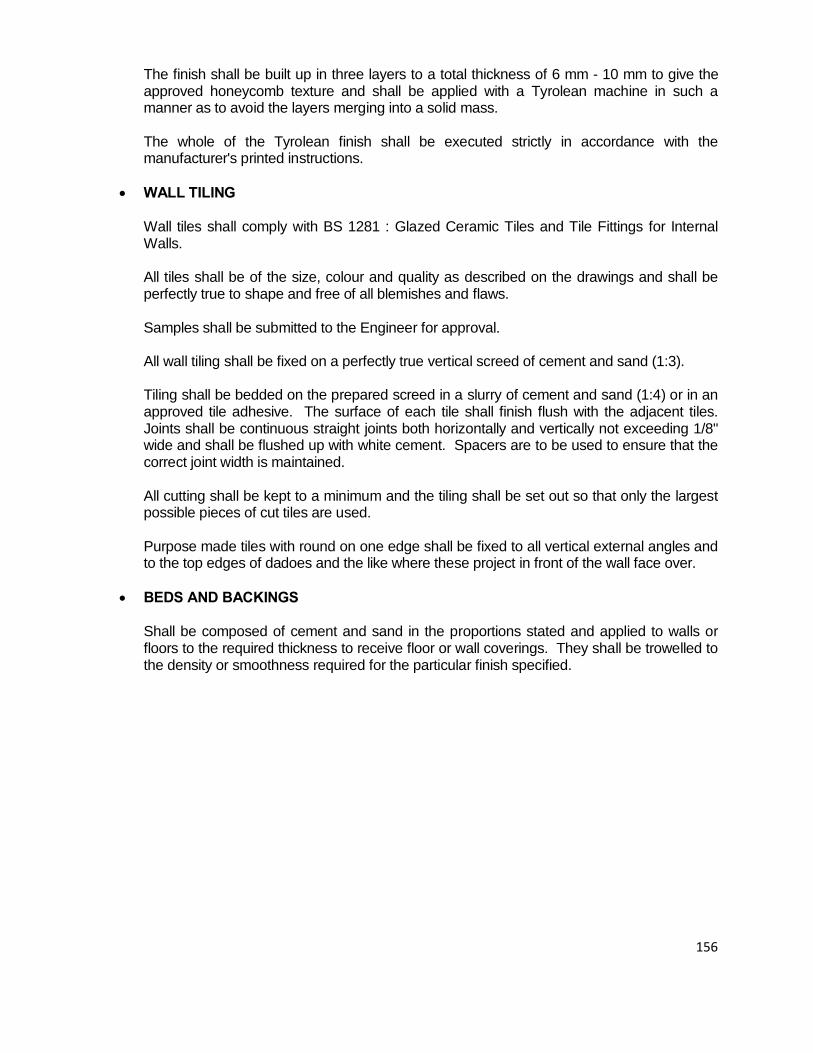
156
The finish shall be built up in three layers to a total thickness of 6 mm - 10 mm to give the approved honeycomb texture and shall be applied with a Tyrolean machine in such a manner as to avoid the layers merging into a solid mass.
The whole of the Tyrolean finish shall be executed strictly in accordance with the manufacturer's printed instructions.
• WALL TILING
Wall tiles shall comply with BS 1281 : Glazed Ceramic Tiles and Tile Fittings for Internal Walls. All tiles shall be of the size, colour and quality as described on the drawings and shall be perfectly true to shape and free of all blemishes and flaws.
Samples shall be submitted to the Engineer for approval.
All wall tiling shall be fixed on a perfectly true vertical screed of cement and sand (1:3). Tiling shall be bedded on the prepared screed in a slurry of cement and sand (1:4) or in an approved tile adhesive. The surface of each tile shall finish flush with the adjacent tiles. Joints shall be continuous straight joints both horizontally and vertically not exceeding 1/8" wide and shall be flushed up with white cement. Spacers are to be used to ensure that the correct joint width is maintained.
All cutting shall be kept to a minimum and the tiling shall be set out so that only the largest possible pieces of cut tiles are used.
Purpose made tiles with round on one edge shall be fixed to all vertical external angles and to the top edges of dadoes and the like where these project in front of the wall face over.
• BEDS AND BACKINGS
Shall be composed of cement and sand in the proportions stated and applied to walls or floors to the required thickness to receive floor or wall coverings. They shall be trowelled to the density or smoothness required for the particular finish specified.

157
• GLAZING
• GLASS QUALITY
All glass shall be of British manufacture in accordance with BS 952 free from flaws, bubbles, specks and other imperfections cut to size to fit the opening for which it is required with not more than 1/19" play all round.
• GLASS GENERALLY
The glass for glazing generally shall be clear sheet and flat drawn sheet and shall be Ordinary Quality (O.Q.) sheet glass. Plate glass where required shall be Glazing Quality (G.Q.) standard plate glass.
• GLASS LOUVRES
Glass for louvres shall be of the thickness stated cut to correct sizes with edges rounded and polished.
• PUTTY
The putty for glazing shall be tropical putty of approved manufacture suitable for glazing to metal or wood frames as specified.
All putty shall be delivered on site in the original manufacturer's sealed cans or drums and used direct therefrom with the addition only of pure linseed oil if necessary. No mineral or other oils may be used.
The rebates of metal windows shall be painted on coat before puttying. Before glazing, the rebates of all windows shall be adequately back puttied.
The putty shall within 14 days dry and harden without wrinkling of the surface or caking and shall adhere satisfactorily to the surface of the glass and the frame.
• GLAZING
All glazing to wood frames shall be sprigged and to metal frames fixed with clips. All glass shall be properly backputtied, and the front putty finished neatly and cleanly.
The washleather and felt strips shall be approved by the Architect and shall be cut to fit the exact line of bead.
• CLEAN ALL GLASS AT COMPLETION
Clean all glass inside and out, remove all paint and putty marks and replace any broken, scratched or cracked panes and leave all glazing sound and perfect at completion.

158
• PAINTING AND DECORATING
• GENERALLY Painting and decorating shall be executed by an approved Sub-Contractor.
All paints, undercoats, primers and preparatory materials shall be obtained from a source or sources approved by the Architect and must not be varied without express authority given in writing and shall be applied strictly in accordance with the manufacturer's printed instructions or as otherwise directed. All materials shall be delivered on Site intact in the original containers and shall be mixed and applied strictly in accordance with the manufacturer's printed instructions. No addition will be allowed to be made locally without the express permission of the Architect.
The priming, undercoats, and finishing coats shall each be of differing tints, the priming and undercoats shall be the correct brands and tints to suit the respective finishing coats, in accordance with the manufacturer's instructions. All finishing coats shall be of the colours and type specified by the Architect. Before the painting or decorating is started, the Contractor shall arrange that all other trades have been completed and other tradesmen removed from the vicinity of the area to be painted. All plaster, mortar, concrete, oil or stains of any kind shall be removed by the Contractor from work to be decorated before painting commences.
• PREPARATION
Plastered and rendered surfaces to be decorated shall be allowed to dry for a minimum of four weeks before decoration commences.
Plaster finished with a steel trowel and fair face concrete surfaces shall be well rubbed down, filled and made good as necessary and thoroughly cleaned down immediately before decoration is applied.
Plaster finished with a wood float or other rough textured surfaces of a similar nature shall be made good as necessary and thoroughly brushed clean immediately before decoration is applied. Insulation board or similar surfaces shall be filled, and made good as necessary and lightly brushed down to remove all dirt, dust and loose particles.
Metal work to be painted shall be scaled clean and thoroughly wire brushed.
Woodwork to be painted shall be well rubbed down. All knots shall be covered with good shellac knotting before priming and all defects shall be filled with hard stopping after priming. Plywood shall be brushed filled over the entire surface.
Woodwork to receive finishes other than paint shall have all stains removed, be well rubbed down and have all defects levelled up with hard stopping of a colour to match the adjoining surface.
Woodwork to receive clear finish or polish shall be well rubbed down and the varnish is to be applied with a chamois leather pad, rubbed back with fine graded steelwool between coats and afterwards buffed up to produce an approved finish.

159
• PREPARATION OF PELICAN DRYWALLS FOR DECORATION
Prior to decorating the partitions either with paint or wallpaper, it is necessary that the joints, internal and external corners and screws are flush skimmed. Any repairs and joints wider that 5 mm should be prefilled with the recommended plaster (see below). The board surface must also be inspected. Any loose paper must be pulled off and skimmed over with plaster.
1. Butt-Joints
Four different skim-jointing gypsum plasters are recommended, depending on the magnitude of the contract and the desired decoration.
1.1 Rhinobed (20 kgs Bags)
Rhinobed is used for production joining of Drywall. Rhinobed is applied to the recessed joint and then the jointing tape is bedded into the Rhinobed using a 125 mm taping knife. Ensure that all bubbles are removed. Drying time + 10 minutes. Apply a second layer of Rhinobed with a 250 mm trowel. Allow to set and dry.
1.2 Readymix (20 litre Drums)
Readymix is used in conjunction with Rhinobed. Readymix is applied over the Rhinobed and tape, using a 300 mm trowel to fill the joint completely flush with the rest of the board surfaces. Drying time + 24 hours, before painting or wallpapering.
1.3 Rhinoglide (20 kgs Bags)
Rhinoglide is used for jointing of small drywalls jobs. Rhinoglide is applied in the same sequence as for Rhinobed and Readymix, namely: bed the joint tape into the joint using a 125 mm taping knife. Allow 45 minutes to set and dry. Apply a second layer using 250 mm trowel. Allow 40 minutes to set and dry. Apply third layer suing 300 mm trowel. Again allow 40 minutes to set and dry.
1.4 Rhinolite (40 kg Bags) Rhinolite is used for flush plastering gypsum ceilings and plastering of all internal walls including Drywalls. Rhinolite is specially manufactured as a combined basecoat and finishing plaster and is recommended where a highly polished smooth surface or a textured finish is desired.
2. Internal Corners
Apply tape with Rhinobed to internal corner ensuring that the tape is evenly spaced either side. When set or dry apply a second and third coat or Readymix to each side using a 125 mm taping knife. Allow one side to dry before beginning the other side. Alternatively Phinoglide or Rhinolite could be used, using the above method.
3. External Corners
Butter the corner bead with Rhinobed. Press firmly into position and secure with drywall screws. Apply a layer of Rhinobed to each side of the corner bead using the 125 mm taping knife. When set and dry apply a second and third layer of Readymix to each side using a 250 mm trowel. Again Rhinoglide or Rhinolite could be used, in the same manner.

160
4. Screws Screws can be flushed using a 125 mm taping knife. Apply a small amount of compound over the screw head in one direction and wipe in a right angle direction. Allow to dry. Apply second and third coat in the same way.
5. General
In all points, 1 – 4, it must be remembered to clean off all excess compound and feather out.
When all coats are dry, sand lightly using a fine grit sandpaper 100 grit). Do not over sand. Decoration:
Undercoat: A good quality water based emulsion paint must be applied directly to the surface of the Rhinoboard. DO NOT use oil or solvent based undercoats.
Finihsing coat: Use any good quality paint.
• PLASTIC EMULSION PAINTS
Plastic emulsion paint for internal or external application shall be as recommended by the Paint Manufacturer.
The first coat in each case shall be thinned with 25% water and all subsequent coats applied undiluted.
• BITUMINOUS SOLUTION
Bituminous solution for use on coated pipes shall be of approved manufacture.
• PRIMERS Unprimed steelwork shall be primed with Red Lead Primer. Galvanised steelwork shall be primed with Zinc Chromate Primer. Woodwork shall be primed with an approved Wood Primer.
• UNDERCOATING
The Undercoat for use under enamel finishing coats shall be of approved quality as recommended by the Manufacturer.
• ENAMEL
Enamel finishing coats shall be of approved manufacture and in accordance with the colour chart.
• METHOD OF APPLICATION
After each coat the work shall be allowed to dry and shall then be well rubbed down with fine glass paper on blocks or other means as required for the particular work before the next coat is applied. The paint work shall be finished smooth and free from brush marks.

161
GENERAL SPECIFICATIONS PART III
ELECTRICAL AND MECHANICAL WORKS

162
• GENERAL SPECIFICATION FOR PLUMBING INSTALLATION • GENERAL REQUIREMENTS 1.01 Introduction
This specification details the requirements for the materials supply, installation, testing and commissioning of the Plumbing and fire fighting installation as shown on the Contract Drawings.
The Sub-Contractor shall include for all appurtenances and appliances not necessarily called for in this specification or shown on the Contract Drawings but which are necessary for the completion and satisfactory functioning of the contract works.
If there is a difference between the requirements of this Specification and the Contract Drawings or lack of clarity in either specification or the Contract Drawings, the Contractor must clarify such differences with the Engineer before tendering. No claim for extra payments shall be entertained from the Contractor due to failure to comply with this requirement.
1.02 Scope of Works
The Sub-Contract works shall comprise the supply and installation of all the sanitary appliances, the internal drainage system up to the nearest man-hole outside the building, the internal cold and hot water supply and storage system, the external water reticulation system, together with the installation of the fire fighting equipment all as shown on the Contract Drawings and as here-in specified.
• Regulations and Standards
All the Plumbing works shall be carried out by a licensed and experienced plumber under the Government Regulations. The work shall be executed in accordance with the best principles of modern plumbing practice. The Contractor shall be responsible for ensuring compliance with all the governing regulations and in particular, his attention is drawn to the following specific codes and regulations:-
a) The Local Authority by-laws and regulations b) The current Republic of Kenya Building Code c) The M.O.W latest issue of “General Specification for Building Works” d) B.S. 5572 - Code of practice for sanitary pipework e) B.S. 8301 - Code of practice on building drainage f) B.S. 6465 - Sanitary Appliances g) B.S 5955 - Code of Practice for uPVC pipework

163
h) C.P. 310 - Water Supply i) B.S. 6700: 1987 - Water supplies within buildings j) The I.E.E Regulation k) The Kenya Bureau of Standard (K.B.S) Specification
All plumbing shall be executed in accordance with Regulations of the Local Authorities and the Water Supply Companies. The Contractor shall give all Notices and pay all fees required thereunder. The amount of such fees shall be deemed to be included in the Contract Sum unless otherwise expressly stated.
• Occupation Certificate The plumbings Contractor shall upon completion obtain an “Occupation Certificate” from the Local Authority and forward it to the Engineer. The cost of obtaining the certificate shall be deemed to be included in the Contract Sum.
1.05 Materials and Standards All equipment and materials shall be new, strong and of durable construction. All the items must meet the relevant quality standards and of reputable manufacture. Safety devices such as pressure relieve valves, thermal expansion joints, thermal and over-load protectors etc must be installed wherever deemed necessary.
1.06 Builders Work Holes, trenches and wall chase in building fabric to accommodate pipes, cable trays etc., together with concrete plinths for pumps, tanks etc. shall be carried out by the Main Contractor at no cost to the Sub-Contractor. However, the Sub-Contractor must inform the Main Contractor of his requirements well in advance to allow such requirements to be incorporated before casting of the building fabric. Drill holes in concrete for anchor channels, clamps, supports etc. shall be carried out by this Sub-Contractor but he must liaise with the Main Contractor before carrying out such works. The Sub-Contractor shall not make any holes nor cut the building fabric without the express consent of the Structural Engineer and consultation with the Main-Contractor.
• Water meters These shall be to BS 5728 part I and I.S. 4064/1. The meters shall be suitable for water temperature upto 30 O C and 10 bar Nominal pressure. These shall have counter registration in cubic meters (or liters), and be able to register down to 1 litre of water volume. These shall be installed to the requirements of BS 5728 part 2 and to the approval of the local council. The subcontractor shall on behalf of the client apply for and secure the meter connection from the Local Authority. He shall therefore allow for all the costs for permits, materials and attendance in connection thereof.

164
• WATER SUPPLY INSTALLATION: • Galvanised Mild steel pipes
Tubing shall be galvanised mild steel to B.S. 1387, with tapered pipe thread to B.S 21:1985. These shall be medium gauges for general use and heavy gauge for underground use, with screwed and socketed joints and of approved manufacture. Tubes must be cleanly finished with smooth surfaces, free from defects and scales.
All pipes below ground are to be protected by coating with bitumen reinforced with glass fibre tissue, hessian cloth or other approved material. Fittings shall be galvanised wrought steel to B.S 1740, with B.S. thread, or galvanised malleable cast iron to B.S. 143 and 1256, of approved manufacture, for use with galvanised steel pipes to B.S. 1387. Castings must be smooth and free from blow holes, pittings and other defects. Where flanged connections are used, these shall comply with B.S. 4504, welded or screwed .All flanges shall withstand a Nominal pressure of 1.6 Mpa (PN 16) and shall be of either grey cast iron or steel. Flanged joints shall have gaskets complying with B.S. 4865 part 1 of 1972, for pressures upto 6.4 Mpa (64 bars). Galvanising of pipes and fittings shall be to B.S. 729:1971
2.02 Copper Pipework Copper pipes shall be used to B.S. 2871:1971 part 1, of approved manufacture. These must be solid drawn, round, clean, smooth and free from all defects and deleterious films in the bore. Fittings shall be capillary or compression type to B.S. 864:1983 Part 2, of approved manufacture, free from internal fins and designed for minimum resistance of fluid flow. Compression fittings to be type A (Non-manipulative), unless otherwise specified.
Copper tubing is to be used as shown on the drawings and as connection tube between steel pipe work and sanitary/laboratory fittings. In order to avoid direct contact a brass straight connector shall be positioned between the steel tube and the copper tube.
• u.P.V.C. Cold Water Service Pipe System
Pipes shall comply in all respects with British Standard 3305:1968 and shall bear the British Standard Kite Mark together with the appropriate class colour coding at one metre intervals. Fittings shall comply in all respects with British Standard 4346 Part 1:1969 and shall bear the British Standard Kite Mark. Pipes shall be supplied in plain-ended lengths.
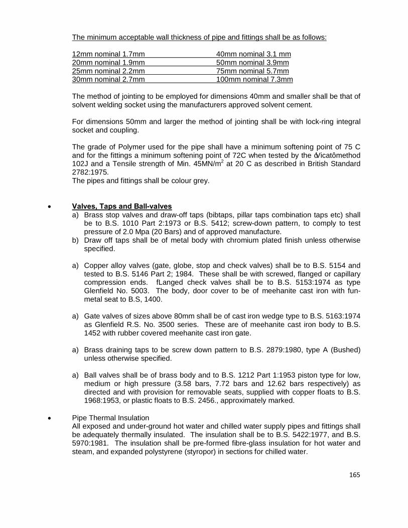
165
The minimum acceptable wall thickness of pipe and fittings shall be as follows: 12mm nominal 1.7mm 40mm nominal 3.1 mm 20mm nominal 1.9mm 50mm nominal 3.9mm 25mm nominal 2.2mm 75mm nominal 5.7mm 30mm nominal 2.7mm 100mm nominal 7.3mm The method of jointing to be employed for dimensions 40mm and smaller shall be that of solvent welding socket using the manufacturers approved solvent cement. For dimensions 50mm and larger the method of jointing shall be with lock-ring integral socket and coupling. The grade of Polymer used for the pipe shall have a minimum softening point of 75 C and for the fittings a minimum softening point of 72C when tested by the ‘Vicat’ method 102J and a Tensile strength of Min. 45MN/m2 at 20 C as described in British Standard 2782:1975. The pipes and fittings shall be colour grey.
• Valves, Taps and Ball-valves
a) Brass stop valves and draw-off taps (bibtaps, pillar taps combination taps etc) shall be to B.S. 1010 Part 2:1973 or B.S. 5412; screw-down pattern, to comply to test pressure of 2.0 Mpa (20 Bars) and of approved manufacture.
b) Draw off taps shall be of metal body with chromium plated finish unless otherwise specified.
a) Copper alloy valves (gate, globe, stop and check valves) shall be to B.S. 5154 and tested to B.S. 5146 Part 2; 1984. These shall be with screwed, flanged or capillary compression ends. fLanged check valves shall be to B.S. 5153:1974 as type Glenfield No. 5003. The body, door cover to be of meehanite cast iron with fun-metal seat to B.S, 1400.
a) Gate valves of sizes above 80mm shall be of cast iron wedge type to B.S. 5163:1974 as Glenfield R.S. No. 3500 series. These are of meehanite cast iron body to B.S. 1452 with rubber covered meehanite cast iron gate.
a) Brass draining taps to be screw down pattern to B.S. 2879:1980, type A (Bushed) unless otherwise specified.
a) Ball valves shall be of brass body and to B.S. 1212 Part 1:1953 piston type for low, medium or high pressure (3.58 bars, 7.72 bars and 12.62 bars respectively) as directed and with provision for removable seats, supplied with copper floats to B.S. 1968:1953, or plastic floats to B.S. 2456., approximately marked.
• Pipe Thermal Insulation
All exposed and under-ground hot water and chilled water supply pipes and fittings shall be adequately thermally insulated. The insulation shall be to B.S. 5422:1977, and B.S. 5970:1981. The insulation shall be pre-formed fibre-glass insulation for hot water and steam, and expanded polystyrene (styropor) in sections for chilled water.

166
The insulation shall be covered with proprietary cladding material or, where no proprietory material exists, with cotton canvas for indoor pipework and o.25mm thick aluminium sheet or foil for external and under-ground piping. The sheet jointing shall be water proofed to the Engineers approval. Underground Cladding shall be finished with two coats of bituminous painting. Pipe insulation thickness for hot water supply shall be as given in the table below; and the density of the fibre glass shall be 100 kg/c.m., and 0.045 w/m2 oC declared max. thermal conductivity.
• Pipe diameter 15-20mm 25-80mm 100-200mm Insulation thickness 20mm 25mm 30mm
All lagged pipes which run in a visible position after erection shall be given a canvas cover prepared for painting as follows:
a) Apply a coating of suitable filler until the canvas weave disappears and allows to dry. b) Apply two undercoats of an approved paint and finish in suitable gloss enamel to
colours approved by the Engineer. All lagging for cold and hot water pipes erected in crawlways, ducts, and above false ceilings which, shall be covered with a reinforced aluminium foil finish and banded in colours to be approved by the Engineers. In all respects, unless otherwise stated, the hot and cold water installation shall be carried out in accordance with the best standards of modern practice as described in C.P. 342 and C.P. 310 respectively, to the approval of the Engineer. Hot water pipes chased in walls shall be wrapped with hair felt or tobacco paper and secure with copper wire.
• Jointing of Water Supply Pipework a) All joints must be air tight and water tight. b) Compounds containing red-lead shall not be used in jointing water supply pipes. c) Steel pipes shall be screwed together using an approved compound/proprietary
thread tape. Exposed threads above ground shall be rust-proof painted using non-toxic bituminous paint while those to be buried shall be thickly coated with bitumen.
a) Joints of copper to steel pipes of less than 38mm diameter shall be by copper unions or union ferrules. Those of 38mm diameter and above shall be by screw, braze, or weld copper flange to copper pipe jointing to steel flange with copper allow bolts and nuts.
Before any joint is made, the pipes shall be hung in their supports and adjusted to ensure that the jointing faces are parallel and any falls which shall be required are achieved without springing the pipe.
Where falls are not shown on the drawings or stated elsewhere in the specification, pipework shall be installed parallel to the lines of the building and as close to the walls, ceilings, columns, etc., as is practicable.

167
a) All water systems shall be provided with sufficient drain points and automatic air
vents to enable them to function correctly
Before any joint is made, the pipes shall be hung in their supports and adjusted to ensure that the jointing faces are parallel and any falls which shall be required are achieved without springing the pipe. Where falls are not shown on the drawings or stated elsewhere in the specification, pipework shall be installed parallel to the lines of the building and as close to the walls, ceilings, columns, etc., as is practicable. All water systems shall be provided with sufficient drain points and automatic air vents to enable them to function correctly. Valves and other user equipment shall be installed with adequate access for operation and maintenance. Where valves and other operational equipment are unavoidably installed beyond normal reach or in such a position as to be difficult to reach from a short step ladder, extension spindles with floor or wall pedestals shall be provided. Screwed piping shall be installed with sufficient number of unions to facilitate easy removal of valves and fittings, and to enable alterations of pipework to be carried out without the need to cut the pipe. Full allowance shall be made for the expansion and contraction of the pipework, precautions being taken to ensure that any forces produced by the pipe movements are not transmitted to valves, equipment or plant. All screwed joints to piping and fittings shall be made with P.T.F.E tape or Boss white proprietory compound.
• Expansion Joints and Anchors
Where practicable, hot water pipework systems shall be arranged with sufficient bends and changes of direction to absorb pipe expansion providing that the pipe stresses are contained within the working limits prescribed in the relevant B.S. Specifications. Where piping anchors are supplied, they shall be fixed to the main structure only. Details of all anchor design proposals shall be submitted to the Engineer for approval before erection commences. When arranging piping it shall be ensured that no expansion movements are transmitted directly to connections and flanges on pumps or other items of plant. Flexible joints shall be supplied to prevent vibrations and other movements being transmitted from pumps to the piping systems or vice versa. All bends, valves and hydrant tee etc. in the line of the water mains shall be adequately anchored to resist thrust due to internal water pressure. A concrete block shall be cast under and the around the pipe and between it and the sides of the trench. Well rammed materials shall be used to support the pipe on either side of the concrete.
• Pipe Supports and Fixings
(a) General This sub-clause deals with pipe hangers, slider and roller type supports, clamps, cages,

168
cantilevers etc supports securing pipes to the structure of buildings for above ground application. These shall be manufactured to B.S. 3974. The variety and type of supports shall be kept to a minimum and their design shall be such as to facilitate quick and secure fixings to metal, concrete, masonry or wood. Consideration shall be given, when designing supports, to the maintenance of desired pipe falls and the restraining of pipe movements to a longitudinal direction only. Pipes shall be fixed in a position which leaves the lower surfaces at the same horizontal level, unless otherwise instructed. Pipes shall be fixed to true lines parallel to adjacent lines of the building unless otherwise specified. Where insulated, pipes shall be fixed with the insulation at least 25mm clear of adjacent surfaces. The Plumbing Contractor shall apply and install all steelwork forming part of the pipe support assemblies and make good any damage to builder’s work associated with the pipe support installation. All proposals for pipe supports shall be submitted to the Engineer for approval before any erection work commences. b) Spacing for Pipe Supports Pipe runs shall be secured by pipe clips connected to pipe hangers, wall brackets or trapeze type supports. ‘U’ bolts shall not be used as a substitute for pipe clips without the prior approval of the Engineer. An approximate guide to the maximum permissible supports spacings in meters for steel and copper pipe and tube is given in the following table for horizontal runs.
Size Nominal Bores
Copper Tube To B.S. 2871
Steel Tube To B.S. 1387
15mm 1.25mm 2.0m 20mm 2.0m 2.5m 25mm 2.0m 2.5m 32mm 2.5m 2.7m 40mm 2.5m 3.0m 50mm 2.5m 3.0m 65mm 3.0m 3.5m 80mm 3.0m 3.5m 100mm 3.0m 4.0m 125mm 3.5m 4.5m 150mm 4.5m 5.5m The Support spacings for vertical runs shall not exceed one and half times the distances given for horizontal runs, or as given by the manufacturers.

169
b) Pipe Sleeves Where pipes pass through concrete or block wall, pipe sleeves of galvanised steel tube shall be used; these shall be of sufficient sizes to give at least 3mm clearance around the pipe. The annular space shall be filled with bitumastic material and caulked at the ends.
• Trench Excavation – Water Main
As described in B.S 8301 Clause 18 and the following:- (a) The Contractor shall excavate the pipe trenches in the line to the depths indicated by
the Engineer. Except where otherwise indicated on the drawings or directed by the Engineer, all pipes must have a minimum cover of 500mm over top of the barrel of the pipe when laid, plus or minus a tolerance of 75mm either way. All trenches shall be excavated in open cuttings.
(a) Where the trench passes through grassland, arable land or garden, whether enclosed or otherwise, the turf, if any, shall be pared off and stacked, and the productive soil shall be carefully removed from a width of 600mm greater than the normal trench width, or equal to the overall width of track of the excavating machine whichever is greater, and laid aside to be subsequently used in reinstating the surface of the ground after the trench has been refilled.
(a) The bottom of the trench shall be properly trimmed off, and all low places or irregularities shall be levelled up with fine material. Where rock or large stones are encountered, they shall be cut down to a depth of at least 75mm below the level at which the bottoms of the barrels of the pipes are to be laid, and covered to a like depth with fine material (sand or red soil) so as to form a fine and even bed for the pipes.
(a) Joint holes shall be excavated to such minimum dimensions as will allow the joints to be well and properly jointed.
(a) The pipe trench shall be kept clear of water at all times.
(a) The Contractor shall, wherever necessary, by means of timbering or otherwise, support the sides of the trench so as to make them thoroughly secure, and afford adequate support to adjoining roads, lands, building and property, during the whole time the trench remains open and shall remove such timbering when the trench has been backfilled. The cost of such timbering or other work shall be deemed to be included in the rates for excavation and backfilling. In case the Contractor is instructed by the Engineer to leave any portion of such timber in position, he will be paid for it accordingly.
(a) The clear width inside the timbering, in the case of single pipes shall be at least 320mm in excess of the external diameter of the pipe being laid, in order to allow it to be freely lowered into position in the trench without damage to the external protection.
(a) Where more than one pipe is to be laid parallel, then the clear width inside the timbering shall be at least 520mm in excess of the combined external diameters of the pipes.

170
(a) Any excavation below the specified depth, in error or otherwise, shall be refilled to
the correct levels, at not extra cost, with mix 1:3:6 concrete or other approved material.
(a) If a mechanical excavator is used by the Contractor, he shall indemnify the Employer against all claims for damage which, in the opinion of the Engineer, may have been caused by the use of this plant. When a mechanical excavator issued the bottom 200mm of excavation shall be excavated by hand to ensure an even bed for the pipes.
• Concrete Bedding, Haunching and Surround
Concrete bedding, haunching and surround shall be provided as necessary of where called for by the Engineer in accordance with the requirements laid down in B.S. 8301:1985 Clause 11.
• Backfilling
Backfilling of trenches, shall be carried out in accordance with the methods described in B.S. 8301:1985 Clause 5.7.6.
• Reinstatement of Surfaces
Following the final backfilling of all trenches and manhole surrounds, the surface of the excavated areas shall be fully reinstated to the approval of the Engineer. Where the excavations have been carried out in public highways or other areas not forming part of the site, prices will be deemed to allow for all charges associated with the temporary and final reinstatement requirements of the Local Highway Authority. No claims for extras in this respect will be accepted.
• Identification of Pipelines
All pipes conveying fluids shall be identified by applying the basic identification colours or the colour code indication as specified in B.S. 1710. The following table is given as a guide.
Pipe Contents Basic identification colour 1. Water Green 2. Drainage Black 3. Steam Silver Grey 4. Fire extinguishing Red 5. Compressed air and vacuum Light Blue 6. Oils Brown 7. L.P.Gas Yellow
The method of application shall be as here-in specified and/or shown on the drawings. • Lettering
The lettering for sluice valves, fire hydrants, air valves and washouts abbreviated SV, FH, AV and WO respectively shall be in accordance with the normal practice and as details shown on the drawings and colour coded as above with letters in white or black on the appropriate background colour.

171
• Surface Boxes
Sluice valves, air valves and fire hydrants shall be covered with surface boxes in accordance with details as shown on the drawings. In roads and footpaths the boxes shall be laid flush with the surface.
• Water Supply Pipework Testing
The whole of the water supply system shall be tested to the approval of the Engineer as follows:- Plug-off valves of main service line and/or terminals in the section to be tested. Fill pipes with drinking water and apply test pressure which shall be the maximum working pressure plus 50%, or as directed by the Engineer. There must be no measurable loss of pressure at the end of one hour and system must be water tight. Open all taps and check for satisfactory rate of outflow. Test all cisterns as directed, at pressure not less than the working pressure. Locate and make good all defects and re-test to the satisfaction of the Engineer.
• Testing – Mains Installation
(a) The test pressure shall be one and a half the maximum working pressure except where a pipe is manufactured from a material for which the relevant B.S. Specification designates a maximum test pressure as in the case of the cast or spun iron pipes, where the test pressures should not exceed 120, 180 and 240 metre/head for Clause B, C, or D pipes, respectively.
The test pressure shall be maintained by the pump for about one hour and if there is any leakage, it shall be measured by the quantity of water pumped into the main in that time.
(a) When a section of the main has been jointed, the ends shall be closed with caps,
plugs, or flanges which must be strongly strutted against a solid surface to the satisfaction of the Engineer. The trench shall be properly backfilled and rammed as herein specified, and as shown on the drawings, for its whole length so as to cover the main to a depth of not less than 500mm, except at the joint places which shall be kept clear of all backfilling, if necessary by the use of timbering, so that each joint is left fully exposed for inspection. No backfilling of joints will be permitted before testing of each section.
As long as a section of main as possible shall be tested at one time subject to the maximum length of open trench approved by the Engineer or permitted by the Highway Authority, and the test shall be carried out within 12 working days of the completion of such sections of mains.
Where a main is laid across a road or in such as position as to interfere seriously with the normal use of the road, the Contractor may, with the consent of the Engineer and at his own risk, fill in such joint holes as may be necessary. He shall, at his own expense, re-excavate any or all joint holes necessary to locate a leak and carry out repair work should the results of his hydraulic test prove unsatisfactory.
The section shall then be filled with mains water, great care being taken to drive out all

172
air through air valves ferrules or otherwise to the approval of the Engineer.
(a) After the section to be tested has been charged and all air liberated it shall remain standing under moderate pressure for several days for final airing.
The leakage from the mains and connections from each section tested shall not exceed 4 liters of water per 25mm diameter of main, per 2 km length each 24 hours, every 30 meters head of pressure, and any visible individual leak shall be repaired.
To determine the rate of leakage, the Contractor shall furnish a suitable hydraulic test pump, pressure gauge, connections and water meter or other appliance, for measuring the amount of water pumped.
If the leakage to be at a greater rate than that specified the Contractor shall re-excavate the trench where necessary and shall remake the joints and replace defective work until the leakage shall be reduced to the allowable amount.
(a) The Employer shall charge the Contractor the cost of any couplings required to join
up tested lengths of main if, in the Engineer’s opinion, greater lengths could reasonably have been tested or if failure under test requires the pipe to be cut, or other methods of laying should have been adopted.
Water used by the Contractor in testing the main shall be supplied by the Main Contractor. The Contractor shall carry out all work which may be necessary for making temporary connections to the existing mains to obtain water for testing at his own expense.
(a) In carrying out the test for watertightness the Engineer only shall authorise the
operation of all valves, but the Contractor shall provide all the necessary labour to assist in the opening and closing of the valves to the Engineer’s instruction, and he shall allow in his prices for all his expenses in connection with testing on completion.
The Engineer shall be the sole judge of watertightness.
• Sterilization of Installation After testing, all the water supply system shall be sterilized before taking into use, and after being opened up for any repairs. Sterilizing shall be done in accordance with C.P. 310:1965 Clause 409, or as detailed below, to the satisfaction of the Engineer.
a) Fill the whole system with drinking water and flash out.
a) Re-fill the system, adding sterilizing chemical gradually as the storage cistern fills.
Use proprietary chemicals, or bleaching powder at the rate of 0.15 kg per 1000 liters.
a) When the cistern is full, open the taps successively working away from the cistern, and closing each tap as the discharge begins to small chlorine.
a) Top up the cistern with water and the sterilizing chemical and leave still for 24 hours.

173
a) Empty system and flush-out thoroughly with clean water. • Cleansing and Sterilizing the Mains
When a pipeline is complete and where applicable, has successfully passed the test, it shall be thoroughly washed out using, if possible an open end. Thereafter it shall be sterilized by being filled with a suitable solution containing not less than 20 p.p.m of free available Chlorine or such other sterilizing agent, as the Engineer shall prove. After standing for 24 hours the main shall again be washed out and refilled with main water prior to the taking of bacteriological samples. The Contractor shall provide all necessary stop ends, fitting and chemicals for this work. Empty and washing out of the pipes shall be done in such a manner as not to damage the trench or cause flooding, and the Contractor shall supply and use such piping, specials and/or hose as may be necessary to facilitate the flow of water to the nearest drain or watercourse. Water used for washing out and sterilizing will be supplied by the Main Contractor. Before any section of the main is put into use a bacteriological sample or samples will be taken in the presence of the Engineer and only on receipt of satisfactory certificate from the Medical Research Laboratory will the main or section of main be permitted to be put into supply and be considered as having been substantially completed. Any expenditure involved in providing facilities or materials for the taking of samples shall be included in the Contractor’s tendered rates and the Engineer will specify and shall be the sole judge as to the number of samples required and the points at which they are to be taken. The cost of the bacteriological examination will be borne by the Employer but if the sample or samples are not satisfactory the cost of any subsequent analysis will be borne by the Contractor.
• Existing Installation
Where pipes for cold water are to be connected up to existing installations, the condition of the existing installation it to be reported to the Engineer in order to establish if part of the existing installations is to be replaced or serviced. The Sub-Contractor shall allow for keeping the services in use with minimum interruptions. All service interruptions must be reported and agreed to with the client at least 24 hours in advance.
• Clearance of the Site
The Contractor shall remove all surplus pipes, specials and other fittings from the site, upon completion of the works and prior to handing over. The site of works shall be levelled and all surplus excavation, debris, cut trees or bushes shall be carted to approved tip sites.
• Booster Pumps These will comprise of 2 No. Electrically driven pumps, one for duty and one for standby. The pump vital parts (seal drivers, head cover, intermediate chamber, impeller, shaft, washer outer sleeve etc.) shall be in stainless steel, with tungsten carbide seal ring and cast iron pump head and a maintenance free mechanical shaft seal. This shall be coupled to a totally enclosed squirrel cage 2 pole fan cooler motor.

174
Flange connections on each pump are to be BS 4504NP.16. Each pump is to be supplied with isolating valves, non-return valves and test cocks on the pump body, all as shown on the drawings or elsewhere in this specification. The pump and motors are to be assembled on a mild steel fabricated support base plate which is to be bolted down to a concrete plinth in an approved manner. Flexible coupling with flange connections are to be supplied and fitted to both suctions and delivery pipes to reduce pump vibrations being transmitted via the connection pipework.
• PUMP CONTROL PANEL
The control panel shall house the pump motor starters, selector switches, alarm devices and overload protection gear together with a micro-door switch to isolate all power upon opening the panel door. The panel shall be fabricated from heavy duty sheet steel with stove enamelled finish and clear Perspex front cover, forming a dust and damp proof enclosure. All control buttons and indicator lights shall be mounted on the panel door and suitably labelled and shall include the following:- a) Main isolator switch b) Pump No. 1 switch on push button c) Pump No. 2 switch on push button d) Automatic and manual change-over switches e) Pump running (green light) indicator light for each pump f) Pump failure
• DRAINAGE SYSTEM
MATERIALS AND WORKMANSHIP • Cast Iron Spigot and Socket Pipes
These shall conform to B.S. 416:1973 for above ground pipework and of approved manufacture. Castings must be sound and free from defects, and must ring clearly when struck with a light metal hammer. All pipes and fittings to be coated with tar or bitumen based solution suitable for tropical conditions by the manufacturer. Jointing shall be by packing the joint space with a gasket of firmly caulked tarred yarn, then caulked with molten lead or fibrous lead yarn. Cast iron socketed pipes shall generally be supported at every socket joint by means of either holderbats secured rigidly to the structure, or purpose made straps for attachment to rigid steel support brackets. When holderbats are used, they shall conform to the requirements of B.S. 416. Suitable anchors shall be provided at all changes of pipe direction, junctions and tees, to counteract the effect of end thrust loads.

175
All cast iron pipework, branches, tees, bends and other fittings shall be supplied complete with inspection covers for cleaning purposes. These inspection covers shall be included as part of the fittings and shall comply with the requirements of B.S. 146.
• u.P.V.C. Soil and Water System
The pipes and fittings shall comply in all respects to B.S.S. 4514 and B.S 5255 and shall where appropriate bear the British Standard Kite Mark. Pipe will be supplied in plain ended lengths. The minimum acceptable wall thickness of pipe and fittings will be as follows:- 32mm pipe 1.8mm 40mm pipe 1.9mm 50mm pipe 2.0mm 80mm pipe 3.20mm 100mm pipe 3.20mm 150mm pipe 3.30mm The method of jointing to be employed shall be that of solvent welding using the manufacturers approved cement. Seal ring fittings shall be used where necessary to accommodate thermal movement, or the sockets of standard fittings shall be converted to seal ring joints by the addition of a seal ring adaptor. The grade of Polymer used for the pipe shall have a minimum softening point of 82 deg. C and for the fittings a minimum softening point of 79 deg. C when tested by the ‘Vicat’ method 102D as described in British Standard 2782:1975. The pipe and fittings shall be colour grey, to British Standard 5252:1976, 10.A.07 with the exception of water closet connections, which may be colour white. The rubber seals for seal ring joint shall be of ‘W’ section and shall be to the material requirements of British Standard 2494:1976. Water closet connections shall be to the same British Standard. Water boss connections when fitted to pipes shall consist of two parts with inner and outer flanges, solvent welded as a complete unit with inbuilt gradients for the waste pipes of 1.25 degrees. Where it is not possible to gain access to the bore of the soil pipe, self locking bosses with integral clamping action may be used provided that the mating surfaces are suitable for and used with solvent weld cement. Water boss connections to branch fittings as necessary shall be solvent welded to set positions of its branch fittings. Alternative waste boss connections may be made using unequal junctions conforming to British Standard 4514:1969 with solvent weld joints conforming to the same. Holderbats shall be made of mild steel protected from corrosion by galvanising. They shall have a two position fixing suitable for either acting as pipe support but allowing thermal movement or as a clamp fit on a fitting creating a fixed point. For optimum fit to pipe supports P.C.V packing pieces may be used. Access shall be provided when necessary either by means of an integrally moulded door

176
in an access fitting with an externally fitted rubber seal and secured with two galvanised bolts and nuts or alternatively two-piece clamp type door fitted into the pipe run. The system shall be as described in a ‘Product Handbook’ complying with the recommendations of B.S. 4940:1973.
• u.P.V.C. Rainwater Fittings
All fittings shall be injection moulded and shall be compatible with pipes and gutters/ All gutters, pipes and fittings shall be colour grey to British Standard 5252:1976 10.A.07, or black or white. Gutter connecting fittings shall have integrally moulded seal retaining cavities housing a polychloroprene seal of hollow section. The fittings shall incorporate a gutter retaining clip:- Gutter connecting fittings shall incorporate provision for fixing the fascia boards, rafters or blockwork such that the fixing screws shall not be in contact with the inner surface of the gutter and shall have provision for expansion of the gutter clearly marked in the fitting. The grade of Polymer used for pipes and fittings shall have a minimum softening point of 75 deg.C when tested by the ‘Vicat’ method 102J as described in the British Standard 2782:1975.
Gutters shall be supported on support brackets at one metre centres.
Gutters shall be installed to accommodate thermal movement. Expansion joints shall be provided at maximum 4 metre centres. All rainwater system shall be installed in accordance with the manufacturer’s site work instructions.
• u.P.V.C Underground Drainage System The pipes and fittings shall comply in all respects to British Standard 4660:1973 and shall bear the British Standard Kite Mark. Pipes shall be supplied win plain ended lengths. The minimum acceptable wall thickness of pipe and fittings will be as follows:- 80mm pipe 2.25mm 110mm pipe 3.2mm 160mm pipe 4.10mm 80mm junction 3.2mm 110mm junction only 3.50mm socket 3.80mm body All other fittings 3.20mm socket 3.40mm body 160mm all fittings 4.30mm socket 4.70mm body

177
The method of jointing to be employed shall be solvent weld or lip-seal socketed fittings. Jointing to other materials shall be made in the manner specified by the manufacturer. The grade of polymer used for the pipe shall have a minimum softening point of 82 deg. C when tested by the ‘Vicat’ method 102D as described in British Standard 2782:1975, and for fittings 79 deg.C. The pipes and fittings shall be of colour golden brown approximating to British Standard 381C:1971 No. 414. The seal retaining caps and seal rings shall be black . The rubber for lip seal joints shall be to British Standard 2494:1976. The base of soil and vent stack connection to the below ground drain shall be made with a bend of minimum centre line radius 250 mm. Minor changes of direction where permitted shall be made with a variable bend. Where pipes are laid under floor slab, these shall be laid on 150mm thick concrete class “15” (1:3:6 mix) bed on full width of trench or min. 400mm wide, and the pipe shall be completely surrounded with similar concrete thickness. In all other cases, the pipes shall be laid on prepared ground in trench and backfilling to manufacturer’s recommendations. Pipes shall not be left exposed to the sub during construction period.
• Waste Fitment Traps
a) Standard Traps These shall be generally of the same diameter and material as the waste outlets to which they are connected to or as specified on the drawings. All wastes shall comply to B.S. 3380.
Wastes connected to main drains through an intermediate gully trap may have a trap with a minimum water seal depth of 40mm. All other traps shall have a water seal of minimum depth – 75mm. Bottle traps shall not be used for waste connections to sinks. Copper and copper alloy traps shall be case, solid drawn or hot formed to B.S. 1184. Plastic traps shall be B.S. 3943, of approved manufacture. These and the uPVC pipe work must be supplied by the same manufacturer.
a) Anti-Syphon traps Where specified, anti-syphon traps shall be as manufactured by “Caradon Terrain Ltd”, self-resealing type or by “Marley Extrusions Ltd”, Anti-syphon type, or equal and approved.
• Sealing off Existing Drains and Manholes
Existing foul, surface water and sub-soil drains exposed during progress of work are to be reported to the Engineer. Where not required to be reused seal off with concrete or grout solid as directed. Seal off connection to manholes, demolish walls to 500mm below surrounding ground level and fill remainder of manhole with consolidated approved rubble and cover to level of surrounding ground as directed.

178
• Drain Trenches Excavation of trenches shall be made to such depths as shall be required to obtain proper falls and firm foundation. No permanent construction shall be commenced on any trench until the excavation has been approved by the Engineer. Where trenches have been excavated below the required depths they shall be re-filled to the correct level with Class “10” mass concrete (1:4:8 mix) for indoors and compacted granular or other approved fill for outdoors. Backfilling of the pipe trenches shall be by soft material free from stones and shall be watered and carefully tamped over and around the pipe concrete surround in 300mm layers until they are covered to a depth of 600mm. Subsequent filling is to be in 150mm layers, watered and rammed.
• Cast Iron Man-hole Covers and Frames
Covers and frames shall be to B.S. 497, of approved manufacturer. Covers are to be cleanly cast, free from air-holes, sand holes and voids, and to fit well in the frame. Covers and frames shall be coated using hot applied coal-tar based material complying with B.S. 4164:1980. Unless otherwise specified, covers are to 600 x 450 mm, single or double seal, flat type or recessed top for light or medium duty as specified on the Contract drawings. Heavy duty as “ East Africa foundry works” Medium duty (Grade B): Minimum weight 143 Kg. Light duty (Grade C): Minimum weight 37 Kg. Step irons for deep man-holes, where specified shall be of cast iron to B.S. 1247.
• Sundries
Galvanised steel wire baloons shall be B.S. 416, table 22, of approved manufacture. Vent cowls, weathering slates and aprons for uPVC piping shall be supplied from the manufacture of the plastic pipeworks system. Fixing of all pipework shall be by holder-bats, pipe-rings and fixing clips, screwed, nailed or bolted to the structure to manufacturers recommendations and to the Engineer’s approval.
• Inspection and Testing
All inspection and testing shall be carried out as laid down in B.S. 5572:1978 and to the Engineer’s approval. All apparatus and water for testing shall be provided by the Contractor. Drainage pipework shall be tested as soon as practical after erection. Concealed pipework shall be tested to approval before enclosing. Testing shall be carried out as follows:- a) Carry out air-test as described in B.S. 5572, Clause 12.3.1. b) Carry out water test as described in B.S. 5572, Clause 12.3.2.3. c) Carry out performance tests as described in B.S. 5572 Clause 12.3.3. Keep record of all tests carried out for inspection by the Engineer.

179
• SANITARY APPLIANCES • General
All sanitary appliances shall be installed in accordance with the best standard of modern practice as described in B.S. 6465, and to the approval of the Engineer. The appliances shall be as here-in specified and as described on the Contract drawings. The item specification is given as a guidance only, including manufacturers reference numbers, but the Contractor shall ascertain and procure all the necessary accessories specified or not, but which are required for complete installation and proper functioning of the appliance. The Contractor shall also ensure that all items ordered comply with the general regulations, standard and by-laws as specified in this document. Where specific items are unobtainable, the Engineer shall be entitled to reject any of the alternatives on grounds of appearance or for any other reason, notwithstanding compliance with the terms of this specification.
• Protection
Protection covers for the appliances etc shall be retained during and after fixing as far as possible. None of the equipment for the Contract works shall be used for preparing or soaking materials for washing tools, disposing waste or for any other purpose for which they are not designed. All appliances must be stored under cover and kept dry prior to installation. Where existing sanitary fittings are to be removed or replaced, the fitting is to be removed with utmost care and all fittings and taps to be handed over to the Employer.
• Fixing
All fixtures shall be fixed in accordance with the manufacturer with the manufacturer’s recommendations and to the Engineer’s approval. Fastenings and fixings supplied by the equipment manufacturers shall be used wherever possible.

180
TECHNICAL SCHEDULE The Tenderer must complete the following schedule comprehensively, indicating the names of Manufacturers and/or suppliers and unit types and must submit Technical brochures for the equipment he proposes to supply for the work.
ITEM MANUFACTURE & MODEL Nos. 1. Sanitary Appliances ……………………………………………………………… 1. Stainless steel sinks ……………………………………………………………….
1. Wash Hand Basins ………………………………………………………………..
1. Taps ……………………………………………………………………………….
1. Galvanised Mild Steel pipes
and fittings ………………………………………………………………………...
1. u.P.V.C pipes and fittings (drainage) …………………………………………………………………………. 1. u.P.V.C pressure pipes and
fittings …………………………………………………………………………….
1. Valves ……………………………………………………………………………. 1. Water Tanks ……………………………………………………………………..
1. Laboratory Sinks …………………………………………………….................
1. Hot Water Cylinders ……………………………………………………………...
1. Portable fire fighting units ………………………………………………………..
1. Hose Reels ………………………………………………………………………..
Signature: …………………………..…….. Date: ……………………… 20 ………….
Tenderer

181
PLUMBING INSTALLATION
WATER PIPES TESTING REPORT Project………………………………… Date …………….. 20…….. Foreman/Plumber ……………………………………………………. DATA RECORDED ON SITE Location and Ref. Drawing:
Length/Diameter of Pipe:
Class/Type of pipe
Test Pressure Required
Water filled at –
Test Pressure Reached at –
Loss of Water/Pressure – Reading
1st Hr. 2nd Hr. 3rd Hr. 4th Hr. 6th Hr.
Quantity of water pumped to Retain test pressure:
Allowable Quantity of Leakage
Remarks
Signature: …………………………………. Date: ……………………… 20 ………………... (C.O.W/R.E) Signature: …………………………………. Date: ……………………… 20 ………………... Foreman/Plumber • FIRE FIGHTING/PROTECTION INSTALLATION

182
• PORTABLE FIRE EXTINGUISHERS The Contractor shall supply and install portable fire extinguishers as shown on the Contract Drawings and as directed on site by the Engineer. These shall be containing an extinguishing medium of water, foam powder, carbon dioxide or halon, contained in a metal body, rechargeable or non-rechargeable. The units shall comply in all respects to B.S. 5423:1980 and B.S. 5306 Part 3, 1985. Where fixed on the wall, an appropriate fixing method shall be used, with rawl plugs in the wall to ensure permanent fix. Timber pegs shall not be acceptable for wall fixing. The units shall be supplied sealed to manufacturer’s recommendation and the seal shall be easily breakable to facilitate quick use during fire fighting operation. • HOSE-REEL INSTALLATION The Contractor shall supply and install the hose-reel fire fighting installation all as shown on the Contract Drawings and as directed by the Engineer. The hose reels shall comply in all respects to B.S. 5274:1985; automatic type, with the reel-hose complying to B.S. 3169:1981. Each hose-reel shall be fitted with a screw down globe valve to B.S. 1010, on the inlet to the reel. The hose-reel booster pump shall be of centrifugal type, with a minimum capacity as shown on the drawings. The pump shall be complete with an electric motor, a pressure cylinder, a base plate together with a gate valve and a strainer on the suction side plus a non-return valve on the discharge side all as shown on the Contract Drawings. Control for the pump shall be by a pressure switch. Piping for the hose-reel water supply shall be galvanised steel tubing to B.S 1387:1967, Class B with pipe threads to B.S. 21:1985. Pipe fittings shall be seamless wrought steel to B.S. 1974 Part 1, 1971. Gate valves shall be of bronze body and solid wedge with a non-rising stem and wheel, conforming to B.S. 5154:1983, and generally as Crane type DM 160. Check valves shall be Lift type with bronze body and composition disc conforming to B.S. 5154:1983 and generally as crane type DM 118. All hose-reel supply pipework and fittings shall be painted etching primer and two coats of red enamel paint to comply to B.S. 1710:1984. All painting shall be applied to manufacturer’s instructions. • DRY-RISER INSTALLATION Pipes shall be galvanised steel tubing to B.S. 1387:1967 Class B with pipe threads to B.S. 21. Pipe fittings shall be wrought steel seamless pipe fitting to B.S. 1740 Part 1: 1971. Flanges: steel flanges to B.S. 4504:1969 PN 16. Fire Brigade Breeching inlet shall consist of twin inlets; each inlet consisting of 65mm diameter

183
male instantaneous coupling to B.S. 336 with a non-return valve and a blank cap secured with a short chain. The breeching inlet shall be enclosed in a sheet metal inlet box, finished in ‘fire red’ backed enamel paint, with wired glass door to B.S. 3980. The door shall be secured with spring lock such that it can only be opened from the inside by breaking the glass and releasing the catch on the lock. The door glass front shall be clearly marked with 50mm high red lettering ‘DRY RISER BREECHING CONNECTOR’. Landing valves shall be 65mm diameter gunmetal gate pattern dry riser outlets with flanged inlets and female instantaneous outlets fitted with plugs secured by short chain and conforming to B.S 5041: Part 2:1976. Air Release Valve shall be fixed to the dry riser terminating at least one metre above the topmost landing valve. The above valve shall be automatic air release valve conforming to B.S. 1452. The valve and the dry riser projecting over the roof shall be effectively earthed to prevent damage from lighting. • FIRE HYDRANTS The fire-hydrant system shall comply to the requirements of B.S. 5306 Part 1. The fire hydrants shall be of the screwdown type to B.S. 750 type 2. These shall be of meehanite cast iron body with bronze spindle rings and nut and nickel-plated mild steel bearing plate. Units shall have discharge capacity of not less than 34 1/s (450 gal/min) at a constant running pressure of 1.7 bars. Units shall be installed underground in a concrete block chamber with surface box manufactured from meehanite cast iron (medium or heavy traffic design as specified) all to B.S. 750. The cover shall be inscribed F.H and chained to the box, all as manufacturer by Glenfield Ltd., or equal, approved. An indication plate to B.S. 3251 and of approved manufacture shall be installed at a nearby and conspicuous position. • E. SPRINKLER SYSTEM The specification shall comply with the Fire offices (FOC) rules for ordinary Hazard Group I. This is a wet pipe system that is permanently charged with water under pressure both above and below the installation alarm (wet pipe) valve. • PIPEWORK 1. All pipework above ground shall be heavy grade (class C) galvanized steel conforming to BS 1387 suitable for screwing to BS 21 pipe threads . 2. Pipes laid underground must conform to BS 3505 Unplasticised PVC pipe for cold water

184
supply. 3. Joints must be made with fittings of the manipulative compression type to BS 864 part 2 only. Pipe bending is not allowed. 4. All welding of sprinkler pipework must be carried out in accordance with the provisions of BS 2640, BS 2971 or heating and ventilating contractors’ association manual-welding of mild steel pipework , except that the use of “set in type branches or sockets” and “cut and shut” or “segmented” bends is not permitted. 5. All pipework shall be given 2 coats of red paint.. 6. Slope of pipes for drainage: Sprinkler pipes of installations , whether on the wet , dry or alternate system must be installed such that the system can be thoroughly drained. Sprinkler pipes must be laid to the following minimum slopes:
• Wet pipe systems -2mm in 1 m
• Dry pipe and alternate wet and dry pipe systems with pipe diameter 50mm and above -
4mm in 1 m
• Dry pipe and alternate wet and dry pipe systems with pipe diameter less than 50mm –
12mm in 1 m.
7. Support of pipework: The contractor shall make use of the following items to support the pipework as necessary:
• Hangers • Fasteners • Primary support brackets • Pipe clips • Sling rods • U – bolts and • toggles
8. Spacing and location of hangers: There must be at least one hanger for each pipe section : the distance between hangers for horizontal and vertical sprinkler pipework shall not exceed the following: Nominal diameter of pipe(mm) maximum spacing(m) Less or equal to 65 4.0 More than 65 and upto 100 6.1 More than 100 and upto 250 6.5 • PRESSURE GAUGES 1. On all installations, there must be a pressure gauge (c ) fitted immediately above the alarm
valve and another (b ) immediately below the alarm and main stop valves. 2. Pressure gauges shall conform to BS 1780. The maximum scale value of such gauges
should be of the order of 150 per cent of the known maximum pressure. Pressure gauges must have divisions not exceeding 0.2 bar for a maximum scale value of 10bar, not exceeding 0.5 bar for a maximum scale of 16 bar and not exceeding 1 bar for a maximum scale exceeding 16 bar.
3. Means must be provided to enable each pressure gauge to be readily removed without interruption of installation water supplies.

185
• FITTINGS VALVES Installation control valves: The installation must be provided with a set of installation control valves comprising:
• a main stop valve • an alarm valve suitable for a wet system and • a water motor alarm and gong.
STOP VALVES: 1. All stop valves must be right handed i.e they must be so constructed that in order to shut the valve , the spindle must turn clockwise. The control wheels must be clearly marked showing in which direction the wheel is to be turned to close the valve. There must be an indicator also to show whether the valve is open or closed. 2.The following types of installation valves are allowed:
• Gate / sluice valves designed and constructed to one or other of the following specifications or equal and approved :
• BS 5150- cast iron wedge and double disc gate valves for general purposes • BS 5163- Double flanged cast iron wedge gate valves for water works purposes. • BS 1952-copper alloy gate valves for general purposes • BS 5157-steel gate valve for general purposes.
• Gear operated butterfly valves designed and constructed in accordance with the
following specifications or its equivalent subject to approval----BS 5155 cast iron and carbon steel butterfly valves for general purposes
BALL VALVES Ball valves for use in connection with the incoming water main to be brass gun metal or other corrosion resistant material preferably equilibrium type to BS 1212 (1953) as GLENFIELD AND KENNEDY LTD. All ball valves to be classified as high pressure Ball valves rated at 14.10 kg/sq. cm maximum. CHECK VALVES to be of cast body incorporating flanges , for service of over 54 mm nominal bore to BS 5153 (1974). Services of 54 mm nominal bore and under to be copper alloy to BS 5154 (1974). SPRINKLERS: The sprinklers in this installation shall be 15mm conventional pattern suitable for pendent position and a temperature rating of 68 deg. C. PART B • GENERAL SPECIFICATION FOR ELECTRICAL WORKS A. GENERAL CLAUSES • Regulations This specification covers the requirements of lighting and power installation in Kenya. All

186
apparatus and material supplied and all work carried out shall comply with the Kenya Government Electrical Specifications, GES.1 and GES.2 and local Statutory Regulations. Installations should also be generally in accordance with the requirements of the 16th Edition of the "Regulations of the Electrical Equipment for Buildings" issued by the institution of Electrical Engineers, Which should be used as a “Code of practice" except where they conflict with Kenya Government Legislation regarding electrical installations.
• Standards Except where otherwise indicated in this Specification the Contract Works and all
manufactured items shall comply with the relevant Specification of the British Standards Installation. Such Specification are here in after referred to as "BS". In each case, the latest edition of such Specification shall apply.
Should it be desired to offer equipment covered by other National or International Standards, the approval of the Engineer must be obtained, in Writing, before completion of the tender.
• Records Drawings The contractor shall mark accurately on one set of drawings the conduit laid during the
progress of the work. This information must be made available on site for inspection by the Engineer.
At the completion of the Contract, the Contractor shall supply the engineer with one set of transparent originals, and two complete sets of prints showing the complete installation.
The drawing shall include the location of all apparatus conduits and cable routes and a schematic diagram of the main distribution indicating the phasing of the system.
• Contract Drawings These drawing form part of this specification and are to be read in conjunction with this
specification to enable the contractor to prepare a tender. Where there are any omissions in the bills of quantities, contract drawings supersede the bills of quantities.
These drawings are not intended to be used as working drawings unless they are released for that purpose.
• Working Drawings The contractor shall prepare the working drawings as may be necessary. These shall be
submitted to be Engineer for approval before the execution of the works. Working drawings, to be prepared by the contractor, shall be detailed as below but not
restricted only to these:- 1. General arrangement of drawings showing plants, M.V. Switchgear, distribution boards,
consumer units, fittings, switches, switched sockets outlets etc. 2. Layout drawings of concealed and surface conduits, ducts, trucking etc. 3. Any other drawings that are not called for in the Specification. Two copies of all working drawings shall be submitted to the Engineer for approval. Thereafter, the contractor shall submit copies of approved working drawings for distribution
to the parties concerned. The contractor shall not be relieved of any of this obligations under the contract or from correction any errors on site or elsewhere found subsequently in the approved working drawings by the Engineer.

187
• Labels All switchgear, switch fuses, distribution boards, etc., shall be clearly labeled with black on
white background engraved labels to indicate the name, purpose and position of the gear. All circuits in distribution boards shall be clearly identified in respect of the number and location of the M.C.B. The charts shall be securely fixed inside the covers of the distribution boards.
• Galvanizing Galvanizing shall be applied by the hot process and shall consist of a smooth clean zinc
coating free from defects and be uniform in thickness. The thickness shall be not less than 610gms of zinc per square meter of surface and tested
in accordance with the requirements of B.S 729 where applicable. Sheradiling or other alternative processes shall not be used without approval in writing of the Engineer.
The preparation for galvanizing itself shall not adversely affect the mechanical properties of
the coated material. Surfaces which are normally in contact with oil shall not be galvanized or cadmium plated.
All out-door structures, access ladders, platforms, equipment cubicles shall be galvanized. • Cleaning and painting
Having due regard to the destination and climate conditions under which the plant is to operate, extreme care shall be exercised in the manufacture of the equipment to prevent the formation of any corrosion. All equipment shall be cleaned of all dust, oil, grease, dirt, scale and rust by power tool operated metal brush or preferably by shot or grit blasting and then ground smooth where necessary. Unless otherwise approved, they shall then immediately have applied to them two coats of approved primer paint. After inspection any rough surface shall be filled in and smoothed over and further painting in the factory shall be as follows:-
(a) All interior of cubicles, kiosks, boxes etc., containing wiring or other apparatus and
internal components of the plant which are dispatched to site in an assembled conditions, shall be finish painted with at least two coats of white enamel. The final oat shall be of white anti-condensation finish, where so specified.
(b) The external surface of the panels shall be finished in gray stove enamel to B.S. shade
631 or other shade as may be approved by the Engineer. (c) All interior surface of tanks and other oil filled chambers and external surface of piping
therein shall be painted finally with an oil resisting coating to the approved by the Engineer.
(d) All wall and floor mounted junction boxes, loose starters, etc., throughout the works shall be finished in grey stove enamel or painted finally with to B.S. 381C shade 631 or other shade as may be approved by the Engineer.
After all erection has been made completed at site, the contractor shall make good all
defects in painting and galvanizing which have arisen during transport, storage and erection on site and shall apply undercoat and one finished coat of gloss paint to B.S. 311C shade as may be approved by the Engineer to the external surface of all equipment.
Where galvanized metal work has been damaged it shall either be repaired by cold

188
galvanizing at site or alternatively at the discretion of the Engineer, be returned to the manufacturer for re-galvanizing by the hot process.
• Lighting and Distribution Boards
General lighting and power distribution boards shall comply with the B.S. 3817, 5861 and B.S. 214 and shall be of the metal clad pattern, flush mounted, except where otherwise specified on the drawings.
• Construction Enclosures shall be substantially constructed from 16S.W.G. minimum thickness sheet
steel having hinged front cover, and shall be vermin and insect proof. Each unit shall house M.C.B.’s and shall be supplied complete with bus-bars, earthing terminal, neutral bar, circuit chart, and blanking plate for any spare ways. The incoming isolator switch shall be integral with the distribution board in consumer Units only.
• Miniature Circuit Breakers All distribution boards shall be supplied with M.C.B.'s manufactured to B.S. 3871 and of a
rating as specified on the drawings. The circuit breakers shall incorporate both thermal overload and magnet short circuit tripping, with a trip-free mechanism.
Three phase circuits shall be controlled by integrally manufactured three pole circuit
breakers, with one common operating lever. An intertripping mechanism shall ensure isolation of all three poles in the event of an overload or short circuit on any one phase.
• Earth leakage Circuit Breakers If specified or indicated on the Contract drawings the use of E.L.C.B. for isolation of
incoming supply in the distribution board shall be of an approved type for flush mounting. The general requirements of the E.L.C.B. are as follows:-
(a) It shall have high sensitivity i.e. it shall operate in 30 milliseconds for a leakage current
of 30 milliampere. (b) Its operation shall not rely on the mains supply for tripping under fault conditions. For
example, in the event of a leakage from the live to earth conductor occurring at the same time as break in the neutral supply wire, the breaker shall trip.
• Labeling A circuit chart in each board shall show the name, location and current loading of each
circuit connected. Each board shall be fitted with an engraved identification label in black on white, such as "Distribution Board D.I.", etc, and all three phase distribution boards shall be labeled in white on red, "DANGER 415 VOLTS".
B. NON-METALLIC CONDUIT • Standards and Installation All non-metallic conduits shall be class `A' heavy gauge, high impact, PVC complying with
BS 4606 part 2 type All. The minimum size to be used on the Contract is 20mm external diameter. The required sizes are shown on the Contract drawings. All conduit installation shall be concealed in the walls and floors or in structural slabs.

189
• Joints Conduit will be joined and terminated utilizing the appropriate rigid PVC compounds as
detailed below, or standard conduit entry electrical equipment. Jointing will conform to one of the following techniques:-
No. 1 - Permanent Adhesives - The solvent cement supplied by the conduit manufacturers
will be used to produce a rigid sealed connection. No. 2 - Flexible Adhesive - A non-hardening adhesive supplied by the conduit
manufacturers will be used to produce a flexible sealed joint where allowance is necessary for longitudinal movement (e.g. expansion couplers).
• Bends Bends and sets in the conduit will be made in accordance with the manufacturer’s
instructions. The radius of the bend shall not be less than 2.5 times the outside diameter of the conduit or such greater radius which will facilitate easy drawing in of cables.
• Expansion Adequate allowance shall be made for longitudinal expansion and contraction of the
conduit under normal working temperature variations as follows:- (a) Expansion couplers should be used in straight runs exceeding 6 meters with a loose or
flexible type joint N0.2 above) at the long spout end of the coupler. (b) Saddles as supplied by the manufacturers shall include a sliding support tolerance for
longitudinal expansion.
Special consideration may need to be given to the fixing of accessories where this may prevent natural conduit movements. Over size or slotted fixing holes may be necessary or the introduction of expansion couplers.
• Support Conduits should be supported by saddles, at not more than 900mm intervals. Where
working temperatures tend to be high this should be reduced to 600mm. • Conduit Boxes and Fittings (a) All conduit boxes shall be circular or square pattern of Rigid PVC suitable
for plain connections conforming to sheet 62 B.S. 4607 part 2. Boxes for supporting a fitting or accessory shall be fitted with a PVC lid held in position by means of two 2BA round headed screws Boxes shall have metallic screwed inserts.
(b) Circular or square boxes shall be provided at all outlet points, unless
otherwise specified and lighting fitting, ceiling switches and other accessories will be screwed to the internal lugs of the boxes. Care must be taken when considering the use of totally enclosed fitting with PVC circular boxes where the temperature within the box is likely to rise above 60 C [140 F]. Special steel insert clips should be used in conjunction with circular boxes where heavy pendants are used.
(c) Looping in boxes of circular P.V.C. pattern to sheet 63B.S. 4607 part 2 may
be used in such work as dictated by the structure of the buildings. Conduit entry

190
shall be made by means of P.V.C. bushes.
(d) Adaptable boxes shall be of molded or fabricated PVC of square or oblong shape complete with P.V.C. Lids secured by 2 BA or steel plates round-headed screws. All adaptable boxes and lids of the same size shall be interchangeable. No adaptable box smaller than 75mm x 50mm or larger than 300mm x 300mm shall be employed. Boxes shall be of adequate depth in relation to the size of conduit entering them.
(e) Conduits shall be terminated at adaptable boxes, fuse-board switches, sockets
outlets or other equipment not possessing push-in or threaded spouts, by means of appropriate size female adapter and PVC hexagonal headed Bare Bush. All cemented joints to be made to a depth of not less than the diameter of the conduit being used.
• Earth Continuity Earth continuity shall be provided by a separate insulated conductor drawn into the plastic
conduit and rated in accordance with circuit loadings and appropriate regulations, or as mentioned, on the drawings.
Where required under the Regulations, an earth continuity conductor shall be provided for
lighting fittings in which case the control switches shall be equipped with an appropriate earth terminal.
• Arrangement of Conduit Layout The conduit system shall be carefully planned and erected to avoid unnecessary bends or
changes in direction. Conduits shall be laid in straight horizontal or vertical lines with easy sets. Where several conduits follow similar routes, they shall be laid out from a common center. Where draw-in boxes for right angled change of direction are required in multiple runs, adaptable boxes shall be used for such size as to allow conduits to enter the box without sets. Where conduits are concealed or laid on constructional floors, they shall be secured by fixing as approved by the Engineer. Where it is essential that conduits cross one another in floors, the chases shall be deepened and the conduits set to create the minimum desirable diversion.
Care shall be taken to ensure that there are no obstructions to cables within the conduits
caused by the ingress of plaster, concrete, or other matter. Conduit ends must be square and cleaned of burrs.
• Conduit Draw-in Points Conduits for each circuit shall be completely erected before any cable is drawn in.
Adequate draw-in points shall be provided. Straight runs shall have draw-in facilities at distance not exceeding 12 meters. Runs incorporating sets of bends shall have draw-in facilities at a distance not exceeding 9 meters. These distances may need to the reduced in difficult situations or with particular cable complexes.
Not more than four easy sets, or two right angle bends or sets may be installed between
draw-in points. Solid elbows or tees shall not be accepted. C. FINAL CIRCUIT WIRING • Type

191
All power and lighting wiring cables shall be 600/1000 volt grade, single core, P.V.C. insulated, with stranded copper conductors, manufactured in accordance with B.S. 6006. The minimum size of lighting circuits shall be 1.5 sq.mm sizes, 4.0sq.mm on power spur circuits and 2.5sq.mm on ring main circuits.
• Installation Cables forming circuits connected to different distribution boards shall not be drawn into the
same conduit or draw-in box. The cables shall be coloured in accordance with Table B4 of the IEE Regulations. Cables used on extra low voltage circuits shall be of distinctive colours other than these colours.
No reduction of the strands forming the conductors shall be allowed at switch or other terminals, but all strands shall be effectively secured by screws, nuts and washers or other approved means.
Cables shall be joined together at the terminals of ceiling boxes and other accessories. Under no circumstances will joints be permitted in the run of the cable.
D. P.V.C. INSULATED ARMOURED CABLES • Type These shall be 600/1000 voltage grade to BS.6346 or B.S 6004 having copper wire
insulated, P.V.C. sheathed, single wire armoured and P.V.C. sheathed overall. The cores of four core cables shall be distinctively coloured red, yellow, blue and black. The Contractor shall provide suitable glands and accessories for all armoured cable termination, and where cables are suspended shall provide the necessary rack, cleat or hanger supports and fixing.
Cable supports and racks shall be made by a recognised manufacturer and shall be to the
approval of the Consulting Engineer. All supports and racks shall be arranged as far as is practicable for the easy removal of any
single cable in a multi-cable run, without threading cables through supports and racks. The number of types of supports and racks shall be kept to a minimum commensurate with meeting the requirements of the Contract Works.
• Laying of Cables The work of excavating and back-filling of all trenches for cables, is included in this contract
and the responsibility for positioning, width and depth of trenches, and for laying and bedding of all cables and protective covers is included with the Electrical Works covered by this Specification. Cables shall be laid in trenches at the following minimum depths.
For M.V. cables in open ground 0.55m For M.V. cables under roads and pavements 0.85 Where more than one cable is laid in a trench, cables shall be spaced as follows: Between M.V. cables 0.1m Between M.V. and telephone cables 0.4m Between M.V. and L.V. cables 0.4m Between L.V. and telephone cables 0.4m

192
Between L.V. cables 0.1m
In straight run trenches cable crossings shall not be permitted except where cables branch from the main run. At every draw-in point or junction box the cable should be snaked.
Before cables are laid the bottom of the trench shall be evenly graded and cleared of all loose stones, and shall then be covered with an 80mm layer of sand or sifted soil and lightly compacted, and a further 80mm layer shall be placed on top of the cables. The approved cable protection, see Clause 2.27, shall then be laid and the excavated materials in 0.2m layers, each layer being well compacted by hand or mechanical punners before the next layer is filled.
The width of the trench shall be such that a clearance of 80mm shall be provided between
outermost cable and the side of the trench. Where cables are disposed in more than one layer, the vertical spacing shall be 0.4. between centres of cables or cable groups, the depth of the trench being made suitable accordingly.
• Protective Covers The protective covers, of approved local manufacture to BS.2484 shall be provided over
cables laid in the ground each complete with an interlocking device to prevent lateral displacement. These protective covers shall extend at least 50mm laterally beyond the outside of the outer cable in each group of cables so protected.
• Cable Position Markers These should be placed adjacent to all points where cables change direction, and at all
intervals of not more than 30m and at other positions designated by the Architect or the Consulting Engineer.
• Sealing of Cable Entries Where cables enter a building in pipes, or ducts, the mouths of the pipes or ducts shall be
effectively sealed by means of close fitting solid impregnated wooden plugs and mixture of compound and transformer oil, or other approved manner.
All cables passing through interior walls or floors shall be effectively sealed to the approval
of the Engineer By means of asbestos cement after the cables have been pulled through, in order to prevent the accumulation of moisture and the ingress of debris, sand or vermin. The cost of sealing the cables shall be included in the rates for erection and laying.
• Protection Against Mechanical Damage All cables located in such positions where they are vulnerable to damage by mechanical or
other means shall be protected by suitable lengths of steel pipe bushed to prevent damage to the cable.
• 2.31. Rating Plates Each cable when completely erected shall have permanently attached to it at each end,
and in such intermediate positions as may be considered necessary by the Engineer, metal plates upon which is engraved, or stamped, the identification number of cable together with it supplies. This information shall be recorded by the contractor so that it may appear on drawings of the completed installation.
• Cable Jointing

193
The Contractor shall be wholly responsible for sealing and jointing of all cables supplies and erected under the contract. The cable boxes, loop-boxes and glands for power and L.V. cables on all items of equipment shall be provided under the contract.
Sealing and jointing shall be in accordance with the best current practices and of first class
workmanship. Where cable armouring is used as earth continuity conductors the glands shall have the necessary contact surfaces or straps to provide a low resistance path under fault conditions.
The Tender shall include for all cable jointing where appropriate and also all labour, jointing material and compound, together with the use of all jointer`s tools and making of the tails to the apparatus terminals.
Generally, cable terminations on switchgear, transformers, joint boxes, outgoing, and incoming circuits on the switch-boars shall be glanded in an approved manner.
E. SOCKET OUTLETS • General In all areas, general power outlets shall be of the 13 Amp.3 pin fused plug type complying
with BS. 1363. They shall be flush pattern with white or ivory plates unless otherwise specified on the drawings. Where the circuits are supplied from a common feed, two outlets shall form a twin unit in a common box. The earthing terminal of every socket outlet shall be connected to the earth continuity conductor of the final circuit by an appropriately sized insulated copper conductor. Unless otherwise stated they shall be mounted at 300mm above finished floor level.
• Plugs One fused plug top shall be supplied for each socket outlet installed. Fuses shall be 13
Amp unless otherwise specified. A. FUSED CONNECTION UNITS • General All fused connection units shall be 13 Amp. with fuse and neon indicator lamp. Boxes shall
be flush type with white or ivory copper plates and shall be switched type unless otherwise specified on the drawings.
• Fuses All fused connection units shall be fitted with 13 Amp. fuses, unless otherwise specified. • Labeling The front plate of each fused connection unit shall, unless otherwise specified, be engraved
with the name of the appliance connected to it. G. LIGHTING SWITCHES • Type Lighting switches shall be of the all insulated rocker operating plate switch type to BS. 3676
of ample rating. Switch inserts shall be white set in white or ivory cover plates. Switches controlling points in bathrooms shall be placed outside the bathroom or consist of
a ceiling switch operated by a non-conducting cord, as specified. Switches mounted outdoors shall be of a weather tight pattern.

194
Switches shall be one way, two ways or intermediate as specified and where a number of
switches are mounted together they shall be tilted in a common box. Ceiling switches shall be white or ivory semi recessed pattern, and shall only be used
where specified. Pull cords shall be fitted with shock absorbing springs. H. LIGHTING FITTINGS • General The Contractor shall supply and fit all lighting fittings of the type indicated on the drawings
and in the schedules. All fittings shall be suitable for operation on a 240V, 50Hz supply. Lighting fittings rated other than 240 volts will not be accepted. All lighting fittings shall be supplied with lamps.
• Fluorescent Fittings. Fluorescent fittings shall generally be of the batten type, with control gear contained within
the supporting channel. All fittings shall be supported from conduit boxes, and shall be suspended by two 20mm diameter conduits to give a clearance of 25mm between the top of the fitting and the ceiling. Where fittings are suspended by chains from the ceiling the contractor shall use white flexible cord between the box and the fittings.
The installation of the suspension chain and cord shall be approved on site by the
Engineer. In the ceiling, conduit boxes, to BS. 31, shall be fitted with dome covers, to which the suspension conduits shall be joined, so that the lighting fitting hangs vertically below the conduit boxes.
Fitting shall comply with BS. 3820 or class1, indoor normal atmospheres. All fluorescent fittings shall be fitted with radio interference suppression capacitors and
power factor correction capacitors and shall be earthen. • Reflectors and Diffusers All reflectors for fluorescent fittings shall be made of sheet metal suitably shaped and
stiffened, and shall be of white enamel finish. The diffusers shall be of white enamel finish. The diffusers shall be of white opal type in extruded plastic with external reeding.
• Lamps All lighting fittings shall be supplied complete with lamps of the type and rating specified.
Fluorescent tubes shall be of the "white" type, except where otherwise stated. Pearly type tungsten lamps will be fitted in open fittings.
FLEXIBLE CORDS • General These shall be of 250 volt grade PVC insulated and shall comply with BS.7. Flexible cords
shall not be less than 24/.20(23/.0076).

195
Flexible cords for pendant fittings shall be circular type, heat resistant and white in coluor. J. EARTHING • Earthing Electrodes Earth electrodes shall be minimum 1.4 meters long by 12mm diameter hard drawn copper
rod, and shall be located not less than 3 meters apart at a convenient position 6 meters away from the building. The terminal head of each electrode shall be in a concrete inspection pit, with cover. If the resistance to earth is not satisfactory with one electrode, then additional electrodes or an earth mat shall be provided as directed by the Engineer.
• Distribution System Earthing All distribution boards shall be earthed in accordance with the I.E.E. Regulations. All metal
work associated with the regulations currently in force. • Testing of Earthing System The resistance of the earth continuity system when measured between earthing point and
other point in the installation, including all conduit and metal work which may provide a path or earth, shall not exceed 0.5 ohm where steel conduit forms part or the whole part of the system, or 1.0 ohm, if the earth continuity system is composed entirely of copper, copper alloy or aluminium. When the installation is complete the Contractor shall carry out tests for earth loop impedance, polarity insulation resistance, ring circuit continuity and earth electrode resistance, in the presence of, and to the satisfaction of the Engineer and the K.P.& L.C. The Contractor shall rectify all work not giving test results within the limits prescribed.
• P.M.E. system Provision shall be made for P.M.E. System at supply intake (where applicable) and on the
isolators of the adjacent building. "P.M.E." means that system whereby the neutral conductor of the supply network is earthed at a prescribed number of points along its route, together with the installation earth continuity conductor, at each consumer's installation, so providing a metallic path for the flow of earth fault currents. The connections between the neutral conductor of the installation shall be made by the supply. Authority at the point of intake only. The connection at the isolators will be made by the Contractor in the presence of the Engineer after completion of all tests.
• COMMISSIONING All installations shall be tested to the statutory requirements of the Electricity Authority, and
commissioned in the presence of and to the satisfaction of the Engineer. Four copies of tests reports shall be provided within seven days of carrying out the tests;
and reports shall include full details of how each test was carried out, and a copy of all readings taken.

196
SECTION VIII: BILL OF QUANTITIES Provide here sufficient information, BOQ, on the quantities of Works to be performed.

197
SECTION IX: TENDER FORMS

198
Form of Tender [date] To: [name and address of Procuring Entity] We offer to execute the [name and identification number of contract] in accordance with the Conditions of Contract accompanying this Tender for the Contract Price of Kshs.[amount in numbers], [amount in words] The advance payment required is Kshs. We accept the appointment of [name proposed in Tender Data Sheet] as the adjudicator. or We do not accept the appointment of [name proposed in Tender Data Sheet] as the Adjudicator, and propose instead that [name] be appointed as Adjudicator, whose daily fees and biographical data are attached. We are not participating, as Tenderers, in more than one Tender in this Tendering process other than alternative Tenders in accordance with the Tendering documents. Our firm, its affiliates or subsidiaries, including any subcontractors or suppliers for any part of the contract has not been declared ineligible by the Kenya Government under Kenya’s laws or any other official regulations. This Tender and your written acceptance of it shall constitute a binding Contract between us. We understand that you are not bound to accept the lowest or any Tender you receive. We hereby confirm that this Tender complies with the Tender validity and Tender Security required by the Tendering documents and specified in the Tender Data Sheet. Authorized Signature: Name and Title of Signatory: Name of Tenderer: Address:

199
• Tender-Securing Declaration (Mandatory)
Date: [insert date (as day, month and year)]
Tender No.: [insert number of Tendering process]
Alternative No.: [insert identification No if this is a Tender for an alternative]
To: [insert complete name of Procuring Entity]
We, the undersigned, declare that:
We understand that, according to your conditions, Tenders must be supported by a Tender-Securing Declaration.
We accept that we will automatically be suspended from being eligible for Tendering in any contract with the Procuring Entity for the period of time of [insert number of months or years] starting on [insert date], if we are in breach of our obligation(s) under the Tender conditions, because we;
• Have withdrawn our Tender during the period of Tender validity specified in the Form of Tender; or
• Having been notified of the acceptance of our Tender by the Procuring Entity during the period of Tender validity,
• Fail or refuse to execute the Contract, if required, or
• Fail or refuse to furnish the Performance Security, in accordance with the ITT.
We understand this Tender Securing Declaration shall expire if we are not the successful Tenderer, upon the earlier of;
• Our receipt of your notification to us of the name of the successful Tenderer; or
• Thirty days after the expiration of our Tender.
Signed: [insert signature of person whose name and capacity are shown] In the capacity of [insert legal capacity of person signing the Tender Securing Declaration]
Name: [insert complete name of person signing the Tender Securing Declaration]
Duly authorized to sign the Tender for and on behalf of: [insert complete name of Tenderer]
• Dated on ____________ day of __________________, _______ [insert date of signing] Corporate Seal (where appropriate)
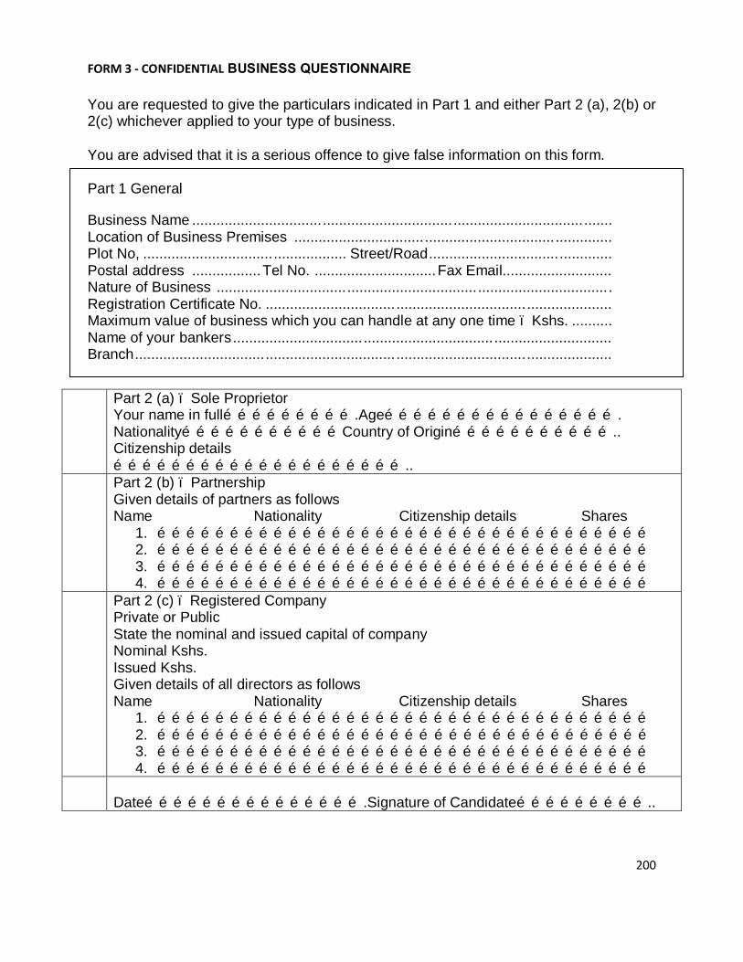
200
FORM 3 - CONFIDENTIAL BUSINESS QUESTIONNAIRE
You are requested to give the particulars indicated in Part 1 and either Part 2 (a), 2(b) or 2(c) whichever applied to your type of business.
You are advised that it is a serious offence to give false information on this form.
Part 1 General
Business Name ....................................................................................................... Location of Business Premises .............................................................................. Plot No, .................................................. Street/Road ............................................. Postal address ................. Tel No. .............................. Fax Email........................... Nature of Business ................................................................................................. Registration Certificate No. ..................................................................................... Maximum value of business which you can handle at any one time – Kshs. .......... Name of your bankers ............................................................................................. Branch .....................................................................................................................
Part 2 (a) – Sole Proprietor Your name in full……………………….Age…………………………………………. Nationality……………………………Country of Origin…………………………….. Citizenship details ……………………………………………………..
Part 2 (b) – Partnership Given details of partners as follows Name Nationality Citizenship details Shares
1. ………………………………………………………………………………………… 2. ………………………………………………………………………………………… 3. ………………………………………………………………………………………… 4. …………………………………………………………………………………………
Part 2 (c) – Registered Company Private or Public State the nominal and issued capital of company Nominal Kshs. Issued Kshs. Given details of all directors as follows Name Nationality Citizenship details Shares
1. ………………………………………………………………………………………… 2. ………………………………………………………………………………………… 3. ………………………………………………………………………………………… 4. …………………………………………………………………………………………
Date……………………………………….Signature of Candidate………………………..

201
PAST EXPERIENCE Bidder to provide details of similar projects (For the listed project bidder must provide Contract documents and completion certificates for completed works or interim certificates for ongoing works) Project name and country
Name of client and contact person
Contractors Participation
Type of work performed and year of completion
Value of contract
(a)
(b)

202
LIST OF MAJOR EQUIPMENTS TO BE PROVIDED BY THE BIDDER Major items of Contractor’s Equipment proposed for carrying out the works. List all information requested below. Item of equipment Description, make,
and age (years) Condition (new, good, Poor) and number available
Owned, leased (from whom?) or to be purchased (from whom?)
(a)
(b)
(c)
(d)

203
FORM 5 - PERFORMANCE SECURITY FORM
To: ……………………………………………………………………………………………..
[name of the Procuring entity]
WHEREAS……………………………….[name of tenderer]
(hereinafter called “the tenderer”) has undertaken, in pursuance of Contract No.___________[reference number of the contract] dated _______________20______to
supply……………………………………………………………………………………..
[Description services](Hereinafter called “the contract”)
AND WHEREAS it bas been stipulated by you in the said Contract that the tenderer shall furnish you with a bank guarantee by a reputable bank for the sum specified therein as security for compliance with the Tenderer’s performance obligations in accordance with the Contract.
AND WHEREAS we have agreed to give the tenderer a guarantee:
THEREFORE WE hereby affirm that we are Guarantors and responsible to you, on behalf of the tenderer, up to a total of ……………………………………………………. [amount of the guarantee in words and figures],
and we undertake to pay you, upon your first written demand declaring the tenderer to be in default under the Contract and without cavil or argument, any sum or sums within the limits of ……………………….. [amount of guarantee] as aforesaid, without your needing to prove or to show grounds or reasons for your demand or the sum specified therein.
This guarantee is valid until the _____ day of 20
__________________________________________________________________ Signature and seal of the Guarantors
____________________________________________________________________ [name of bank or financial institution]
____________________________________________________________________ [address]
______________________________________________________________________ [date]
(Amend accordingly if provided by Insurance Company)

204
Position Name Years of
Experience (general)
Years of experience in proposed position
(a)
(b)

205
BANK GUARANTEE FOR ADVANCE PAYMENT
To…………………………
[name of tender]………………………………………
Gentlemen and/or Ladies:
In accordance with the payment provision included in the special conditions of contract, which amends the general conditions of contract to provide for advance payment,
……………………………………………
[name and address of tenderer][hereinafter called “the tenderer”] shall deposit with the Procuring entity a bank guarantee to guarantee its proper and faithful performance under the said clause of the contract in an amount of ………………………………………………………………………………………… [amount of guarantee in figures and words]. We,the ………………………………………………………………………………
[bank or financial institution], as instructed by the tenderer, agree unconditionally and irrevocably to guarantee as primary obligator and not as surety merely, the payment to the Procuring entity on its first demand without whatsoever right of objection on our part and without its first claim to the tenderer, in the amount not exceeding [amount of guarantee in figures and words].
We further agree that no change or addition to or other modification of the terms of the Contract to be performed thereunder or of any of the Contract documents which may be made between the Procuring entity and the tenderer, shall in any way release us from any liability under this guarantee, and we hereby waive notice of any such change, addition, or modification.
This guarantee shall remain valid and in full effect from the date of the advance payment received by the tenderer under the Contract until [date].
Yours truly,
Signature and seal of the Guarantors ____________________________________________________________ [name of bank or financial institution] _____________________________________________________________ [address] ________________________________________________________________ [date]

206
(Bidders Must declare whether they have litigation or Not)
FORM 7-LITIGATION HISTORY
Name of Contract Supplier
Contractors/Suppliers should provide information on any history of litigation or arbitration resulting from contracts executed in the last five years or currently under execution.
YEAR AWARD FOR OR AGAINST NAME OF CLIENT, CAUSE OF LITIGATION AND MATTER IN DISPUTE
DISPUTED AMOUNT (CURRENT VALUE, KSHS. EQUIVALENT
SIGN………………………………………………..DATE………………………………………..

207
INTEGRITY DECLARATION UNDERTAKING BY TENDERER ON ANTI – BRIBERY POLICY / CODE OF CONDUCT AND COMPLIANCE PROGRAMME • Each Tenderer must submit a statement, as part of the Tender documents, in either of the two
given formats which must be signed personally by the Chief Executive Officer or other appropriate senior corporate officer of the Tendering company and, where relevant, of its subsidiary in the Kenya. If a Tender is submitted by a subsidiary, a statement to this effect will also be required of the parent company, signed by its Chief Executive Officer or other appropriate senior corporate officer.
• Tenderers will also be required to submit similar No-bribery commitments from their
subcontractors and consortium partners; the Tenderer may cover the subcontractors and consortium partners in its own statement, provided the Tenderer assumes full responsibility.
•
• Payment to agents and other third parties shall be limited to appropriate compensation for legitimate services.
• Each Tenderer will make full disclosure in the Tender documentation of the
beneficiaries and amounts of all payments made, or intended to be made, to agents or other third parties (including political parties or electoral candidates) relating to the Tender and, if successful, the implementation of the contract.
• The successful Tenderer will also make full disclosure [quarterly or semi- annually] of
all payments to agents and other third parties during the execution of the contract.
• Within six months of the completion of the performance of the contract, the successful Tenderer will formally certify that no bribes or other illicit commissions have been paid. The final accounting shall include brief details of the goods and services provided that they are sufficient to establish the legitimacy of the payments made.
• Statements required according to subparagraphs (b) and (d) of this paragraph will have
to be certified by the company's Chief Executive Officer, or other appropriate senior corporate officer.
• Tenders which do not conform to these requirements shall not be considered.
• If the successful Tenderer fails to comply with its No-bribery commitment, significant
sanctions will apply. The sanctions may include all or any of the following:
• Cancellation of the contract; • Liability for damages to the public authority and/or the unsuccessful competitors in

208
the Tendering possibly in the form of a lump sum representing a pre-set percentage of the contract value (liquidated).
• Tenderers shall make available, as part of their Tender, copies of their anti-Bribery
Policy/Code of Conduct, if any, and of their-general or project - specific - Compliance Program.
• The Government of Kenya has made special arrangements for adequate oversight of the
procurement process and the execution of the contract, and has invited civil society and other competent Government Departments to participate in the oversight. Those charged with the oversight responsibility will have full access to all documentation submitted by Tenderers for this contract, and to which in turn all Tenderers and other parties involved or affected by the project shall have full access (provided, however, that no proprietary information concerning a Tenderer may be disclosed to another Tenderer or to the public).

209
FROM 8 ANTI-CORRUPTION DECLARATION COMITMENT/ PLEDGE
(Sections 62 of the Public Procurement and Assets Disposal Act, 2015) I/We/Messrs……………………………………………………………………………. of Street, Building, P O Box…………………………………………………………… ………………………………………………………………………………………….. Contact/Phone/E mail………………………………………………………………….. declare that Public Procurement is based on a free and fair competitive Tendering process which should not be open to abuse. I/We ..………………………………………………………………………………….. declare that I/We will not offer or facilitate, directly or indirectly, any inducement or reward to any public officer, their relations or business associates, in connection with Tender/Tender No ………………………..………………………………………………. for or in the subsequent performance of the contract if I/We am/are successful. Authorized Signature................................................................................................ Name and Title of Signatory……………………………………………………………

210
NOTIFICATION OF INTENTION TO ENTER INTO CONTRACT
Address of Procuring Entity
_____________________ _____________________ To: RE: Tender No. Tender Name This is to notify that the contract/s stated below under the above mentioned tender have been awarded to you.
1. Please acknowledge receipt of this letter of notification signifying your acceptance.
2. The contract/contracts shall be signed by the parties within 30 days of the date of
this letter but not earlier than 14 days from the date of the letter.
3. You may contact the officer(s) whose particulars appear below on the subject
matter of this notification.
4. Please note that this Notification does not constitute a contract.
5. You will be required to give a 1% performance bond in form of a Bank Guarantee from bonk registered in Kenya, prior to Contract signing. (FULL PARTICULARS)
SIGNED FOR ACCOUNTING OFFICER

211
FORM OF CONTRACT AGREEMENT This Agreement, made the [day] day of [month], [year] between [name and address of Procuring Entity] (hereinafter called “the Procuring Entity”) and [name and address of Contractor] (hereinafter called “the Contractor”) of the other part. Whereas the Procuring Entity is desirous that the Contractor execute [name and identification number of contract] (hereinafter called “the Works”) with the objectives of [insert functional objectives of the works] and the Procuring Entity has accepted the Tender by the Contractor for the execution and completion of such works and the remedying of any defects therein in the sum of [contract price in words and figures] (hereinafter called “Contract Price”). NOW THIS AGREEMENT WITNESSES AS FOLLOWS: • In this Agreement, words and expressions shall have the same meanings as are
respectively assigned to them in the Conditions of Contract hereinafter referred to, and they shall be deemed to form and be read and construed as pert of this Agreement;
• In consideration of the payments to be made by the Procuring Entity to the Contractor as
hereinafter mentioned, the Contractor hereby covenants with the Procuring Entity to execute and complete the Works and remedy any defects therein in conformity in all respects with the provisions of the Contract;
• The Procuring Entity hereby covenants to pay the Contractor in consideration of the
execution and completion of the Works and the remedying of defects wherein the Contract Price or such other sum as may become payable under the provisions of the Contract at the times and in the manner prescribed by the Contract.
In Witness whereof the parties thereto have caused this Agreement to be executed the day and year first before written. The Common Seal of Was hereunto affixed in the presence of: Signed, Sealed, and Delivered by the said In the presence of: Tendering Signature of Procuring Entity Binding Signature of Contractor

212
SECTION X: FORMS OF SECURITY

213
TENDER SECURITY (BANK OR INSURANCE GUARANTEE) (OPTIONAL) [If required, the Bank or Insurance Company/Tenderer shall fill in this Guarantee form in accordance with the instructions indicated in brackets.] [insert bank’s or insurance company’s name, and address of issuing branch or office] Beneficiary: [insert name and address of Procuring Entity]Date: [insert date]
TENDER GUARANTEE No.: [insert number]
We have been informed that [insert name of the Tenderer; if a joint venture, list complete legal names of partners] (hereinafter called "the Tenderer") has submitted to you its Tender dated [insert date] (hereinafter called "the Tender") for the execution of [insert name of Contract] under Invitation for Tenders No. [insert IFT number] (“the IFT”).
Furthermore, we understand that, according to your conditions, Tenders must be supported by a Tender Guarantee.
At the request of the Tenderer, we [insert name of bank or insurance company] hereby irrevocably undertake to pay you any sum or sums not exceeding in total an amount of [insert amount in figures expressed in the currency of the Purchaser’s Country or the equivalent amount in an international freely convertible currency] ([insert amount in words]) upon receipt by us of your first demand in writing accompanied by a written statement stating that the Tenderer is in breach of its obligation(s) under the Tender conditions, because the Tenderer;
• Has withdrawn its Tender during the period of Tender validity specified by the Tenderer in the Form of Tender; or
• Does not accept the correction of errors in accordance with the Instructions to Tenderers (hereinafter “the ITT”) of the IFT; or
• Having been notified of the acceptance of its Tender by the Procuring Entity during the period of Tender validity;
• Fails or refuses to execute the Contract Form, if required, or
• Fails or refuses to furnish the Performance Security, in accordance with the ITT.
This Guarantee shall expire;
• If the Tenderer is the successful Tenderer, upon our receipt of copies of the Contract signed by the Tenderer and of the Performance Security issued to you by the Tenderer; or
• If the Tenderer is not the successful Tenderer, upon the earlier of;
• Our receipt of a copy of your notification to the Tenderer that the Tenderer was unsuccessful, or
• Thirty days after the expiration of the Tenderer’s Tender. Consequently, any demand for payment under this Guarantee must be received by us at the office on or before that date. _____________________________ [signature(s) of authorized representative(s) ]

214
PERFORMANCE BANK OR INSURANCE GUARANTEE [UNCONDITIONAL] [The Bank or Insurance Company/successful Tenderer providing the Guarantee shall fill in this form in accordance with the instructions indicated in brackets, if the Procuring Entity requires this type of security.]
[insert bank’s or insurance company’s name, and address of issuing branch or office] Beneficiary: [insert name and address of Procuring Entity] Date: [insert date] PERFORMANCE GUARANTEE No.: [insert Performance Guarantee number] We have been informed that [insert name of Contractor] (hereinafter called "the Contractor") has entered into Contract No. [insert reference number of the Contract] dated with you, for the execution of [insert name of Contract and brief description of Works] (hereinafter called "the Contract"). Furthermore, we understand that, according to the conditions of the Contract, a Performance Guarantee is required. At the request of the Contractor, we [insert name of Bank or Insurance Company] hereby irrevocably undertake to pay you any sum or sums not exceeding in total an amount of [insert amount in figures] ([insert amount in words]), such sum being payable in the types and proportions of currencies in which the Contract Price is payable, upon receipt by us of your first demand in writing accompanied by a written statement stating that the Contractor is in breach of its obligation(s) under the Contract, without your needing to prove or to show grounds for your demand or the sum specified therein. We hereby waive the necessity of your demanding the said debt from the Contractor before presenting us with the demand. We further agree that no change, addition or other modification of the terms of the Contract or of the Works to be performed there under or of any of the Contract documents which may be made between you and the Contractor shall in any way release us from any liability under this Guarantee, and we hereby waive notice of any change, addition, or modification. This guarantee shall expire not later than thirty days from the date of issuance of the Taking-Over Certificate. [signature(s) of an authorized representative(s) of the Bank or Insurance Company]

215
BANK OR INSURANCE GUARANTEE FOR ADVANCE PAYMENT [Bank’s or Insurance Company’s Name and Address of Issuing Branch or Office] Beneficiary: ___________________ [Name and Address of Procuring Entity] Date: ________________ ADVANCE PAYMENT GUARANTEE No.: _________________ We have been informed that [name of Contractor] (hereinafter called "the Contractor") has entered into Contract No. [reference number of the contract] dated ______ with you, for the execution of [name of contract and brief description of Works] (hereinafter called "the Contract"). Furthermore, we understand that, according to the conditions of the Contract, an advance payment in the sum [amount in figures] ( ) [amount in words] is to be made against an advance payment guarantee. At the request of the Contractor, we [name of Bank or Insurance Company] hereby irrevocably undertake to pay you any sum or sums not exceeding in total an amount of [amount in figures] ( ) [amount in words] upon receipt by us of your first demand in writing accompanied by a written statement stating that the Contractor is in breach of its obligation under the Contract because the Contractor used the advance payment for purposes other than the costs of mobilization in respect of the Works. We further agree that no change or addition to or other modification of the terms of the Contract or of the Works to be performed thereunder or of any of the Contract documents which may be made between ________________________[name of Procuring Entity] and the Contractor, shall in any way release us from any liability under this guarantee, and we hereby waive notice of any such change, addition or modification. No drawing may be made by you under this guarantee until we have received notice in writing from you that an advance payment of the amount listed above has been paid to the Contractor pursuant to the Contract. The maximum amount of this guarantee shall be progressively reduced by the amount of the advance payment repaid by the Contractor as indicated in copies of interim statements or payment certificates which shall be presented to us. This guarantee shall expire, at the latest, upon our receipt of a copy of the interim payment certificate indicating that eighty (80) percent of the Contract Price has been certified for payment, or on the ___ day of _____, 2___, whichever is earlier. Consequently, any demand for payment under this guarantee must be

216
received by us at this office on or before that date. Yours truly, Signature and seal: Name of Bank or Insurance Company: Address: Date:

217
KENYA RAILWAYS CORPORATION
Viewing Certificate
TENDER FOR PROPOSED RNOVATION OF SECOND FLOOR BLOCK A, KENYA RAILWAYS HEADQUATERS
TENDER NO: KRC/PLM/010/2017-2018
1. The interested tenderer must visit the facility to familiarize with state of the Facilities ______________________________________________________
I hereby certify that I have viewed the building and all related facilities required in the Tender No: KRC/PLM010/2017-2018 and have a good understanding of the requirements under this tender.
1) TENDERERS NAME…………………………………………..………….
SIGN…………………………..………………… DATE……………………………………………..
2) KRC REPRESENTATIVE NAME……………………………………….
SIGN……………………………………….………
DATE……………………………………………..

218
SECTION XI: APPLICATION TO PUBLIC PROCUREMENT ADMINISTRATIVE REVIEW BOARD

219
FORM RB 1 REPUBLIC OF KENYA
PUBLIC PROCUREMENT ADMINISTRATIVE REVIEW BOARD
APPLICATION NO…………….OF……….….20……...
BETWEEN
…………………………………………….APPLICANT
AND
…………………………………RESPONDENT (Procuring Entity)
Request for review of the decision of the…………… (Name of the Procuring Entity) of
……………dated the…day of ………….20……….in the matter of Tender No………..…of
…………..20…
REQUEST FOR REVIEW I/We……………………………,the above named Applicant(s), of address: Physical
address…………….Fax No……Tel. No……..Email ……………, hereby request the Public
Procurement Administrative Review Board to review the whole/part of the above
mentioned decision on the following grounds , namely:-
1.
2.
etc.
By this memorandum, the Applicant requests the Board for an order/orders that: -
1.
2.
etc
SIGNED ……………….(Applicant)
Dated on…………….day of ……………/…20…
FOR OFFICIAL USE ONLY Lodged with the Secretary Public Procurement Administrative Review Board on
………… day of ………....20….………
SIGNED Board Secretary

220
BILL OF QUANTITIES FOR THE WORKS
PRELIMINARIES
A Workmen compensation insurance Item 1 B insurance of works 1
C Allow for protection of other sections of the building and regular cleaning Item 1
D Allow for removal of rubbish/debris/clean up of site after completion
Item 1
E Allow for payment of water bills for use in the works Item 1
F
Allow for making good any affected section of the works including repainting any affected sections in the course of execution of work
Item 1
G Provide for site notice board and
maintaining the same during construction
Item 1
TOTAL CARRIED TO SUMMARY

221
SECOND FLOOR ITEM DESCRIPTION UNIT QTY RATE AMOUNT
GENERAL REPAIR (SECOND
FLOOR)
A
Take out existing painted blockboard partitions complete with timber framing complete with all doors and fitings 3500 mm overall height SM 930
B Hack out wodblock floor finish and prepare surfaces to receive tiles SM 1000
C Remove existing corridor ceiling and prepare surfaces to receive new SM 291
D Allow for polishing of existing terrazzo floor finish along the corridors SM 291
Acoustic tiles E Supply and fix 600 x 600 x 16 mm
"Armstrong Fissured Minaboard" acoustic tiles fixed with metal suspended hangers as specified by manufacturers SM 1000
PAINTING & DECORATING
Construct 200mm thick machine cut stone walling bedded and jointed in cement and sand 1:4 mortar in burnt up section SM 15
F
Prepare and apply three coats silk vinyl emulsion paint to office walls internally. SM 1302
G
Prepare and apply three coats silk vinyl emulsion paint to corridor walls including external walls SM 1703

222
H
Supply and fix 12mm thick imported celotex soft board or as approved equivalent to ceiling along the corridors SM 441
I
Prepare surfaces and apply clear varnish to frames and door surfaces LM 266
J
Prepare surface and apply gloss paint to casement window and doors. SM 250
FLOOR FINISHES
K
Supply and fix ceramic floor tiles as Saj No. 4505 or equal approved fixed to screeded floors with an approved adhesive size 300 x 300mm SM 400
L To skirting. LM 400 Carried to collection DOORS
M
Supply and fix 50mm semi solid core mahogany single leaf door size 900 x 2000mm veneered on both sides with lipping including frames and fanlight NO 26
N
Supply and fix 50mm Solid core single leaf flush door size 900 x 2000mm veneered on both sides with lipping including frames and fanlight NO 5
O
Supply and fix 3 lever mortice lock or approved equivalent complete with furniture. NO 26

223
P Ditto rubber door stops NO 26
Q
Allow for any required repairs to the door leafs to make good previous door locks locations. Item
WINDOWS
MILD STEEL CASEMENT WINDOWS
Purpose made steel casement windows manufactured from heavy duty frames in small panels size 200x250mm high incorporating permanent ventilating units complete with brass windows stays and fasteners; fixed to masonry jambs and concrete heads and cill with mastic pointing all round
R
Windows size 1500 x 1200mm high consisting of two hang lights, one top hung opening lights, one bottom fixed light NO 29
Windows size 1800 x 1200mm high consisting of one top hung opening lights, one bottom fixed light NO 6
S Allow for removal of existing pelmet boxes and store as directed NO 48
T Allow for polishing of terazzo window boards LM 73
U Supply and fix window blinds SM 114 Carried to collection GLAZING
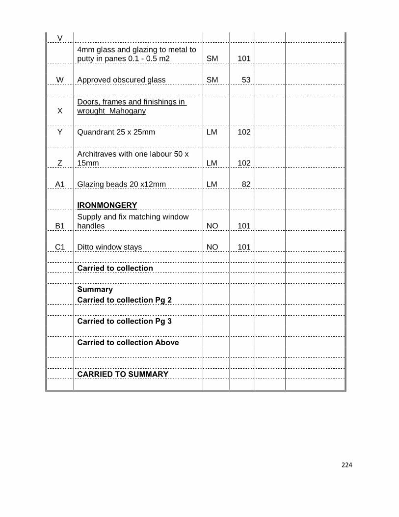
224
V
4mm glass and glazing to metal to putty in panes 0.1 - 0.5 m2 SM 101
W Approved obscured glass SM 53
X Doors, frames and finishings in wrought Mahogany
Y Quandrant 25 x 25mm LM 102
Z Architraves with one labour 50 x 15mm LM 102
A1 Glazing beads 20 x12mm LM 82 IRONMONGERY
B1 Supply and fix matching window handles NO 101
C1 Ditto window stays NO 101 Carried to collection Summary Carried to collection Pg 2 Carried to collection Pg 3 Carried to collection Above CARRIED TO SUMMARY

225
WET AREAS AND FIRE PROTECTION ITEM DESCRIPTION
UNITS
QTY
RATE
AMOUNT
WET AREAS
A Allow for removal of existing wall tiles and preparation of surface to receive new tiles. SM 300
B Allow for hacking of existing terrazo floor finish SM 120
C 25mm cement/sand floor screed to receive ceramic floor tiles. SM 120
D
Supply and fix 200 x 100 x 6mm ceramic wall tiles fixed to walls with an approved adhesive including finishing the joints with matching cement. SM 300
E
Ditto 300 x 300mm Non slip ceramic floor tiles to screeded floor with an approved adhesive including finishing joints with matching cement. SM 120
F Prepare surface and apply three coats of silk vinyl paint to walls internally. SM 450
G Ditto but emulsion paint to ceiling surfaces. SM 120 SANITARY WARE
Supply, install, test and commission the following sanitary fittings and accessories;
H
TWYFORD GALERIE or equal and approved white vitreous water closet (WC) suite comprising- Glazed back inlet WC pan with horizontal outlet and heavy duty unbreakable plastic seat and cover- 7.5litre exposed low level cistern complete with flushing fittings, plastic syphon unit, inlet ball valve, overflow and concelled support bracket. NO 24

226
I
Cerramic white bowl urinal as TWYFORD CAMDEN or equivalent with exposed pipework, comprising of single ceramic 4.5litres automatic cistern supported on hanger,with a range of 3 urinal bowls, Twyford urinal dividers, stainless steel flush pipe screwed to wall with hangers, outlet waste and grating and plastic bottle trap. NO 6
Carried to collection
J
TWYFORD GALERIE or equivalent white vitreous wall mounted wash hand basin size 450 x 340mm complete with wall brackets 1 No. chromed press action delay pillar tap, a 32mm diameter chrome plated pop-up waste and a 32mm diameter plastic bottle trap fixed to manufacturers printed instructions. NO 10
K
STARMIX or equivalent wall mounted push button soap dispenser complete with intill charger and mounting NO 6
L
6mm thick polished bevelled plate glass mirror size 610 x 610mm on foam and 6mm plywood timber backing in hardwood framing on wall with dome headed brass screws NO 10
M
TWYFORD or equal and approved anti-theft toilet roll holder complete with screws for wall fixing in satin alluminium NO 24
N Wall mounted touch free electronic warm air hand drier as STARMIX or equal and approved NO 10
O TWYFORD or equal and approved coat hook in satin alluminium to be fitted in every toilet NO 24
P
Allow for the tesing and commissioning of all sanitary fittings and accessories to the entire satisfaction of the Engineer Item 1
Supply and install uPVC Cylindrical Vertical NO 4 Q 1000lts tank

227
R 10000lts tank NO 1
S Supply and install Cpm 170 1.5 Hp x38 M x 120lts/Min domestic "pedrollo" booster pump NO 1
T Eco- press 1.1KW electronic float control system NO 1 U Float switch NO 1 Carried to collection INTERNAL PLUMBING
Supply,deliver and install galvanised mild steel tubing to BS 1387 Class B with socketed joints to BS 21 and galvanised malleable iron fittings including fixing and jointing. Tendereres must allow in their pipework prices for all the copings,reducers,connectors,joints,e.t.c required in the running lengths of pipework and also where necessary,for pipe fixing clips,holderbats plugged and screwed,brackets and pipe sleeves through structural members
V 13mm diameter GMS tubing Class B LM 120 W 20mm ditto LM 120 X 25mm ditto LM 60 Y 32mm ditto LM 60 Z 40mm ditto LM 10 A1 50mm ditto LM 10 Extra over GMS tubing for the following:- Gate Valves A2 13mm diameter NO 24 A3 20mm ditto NO 10 A4 32mm ditto NO 2
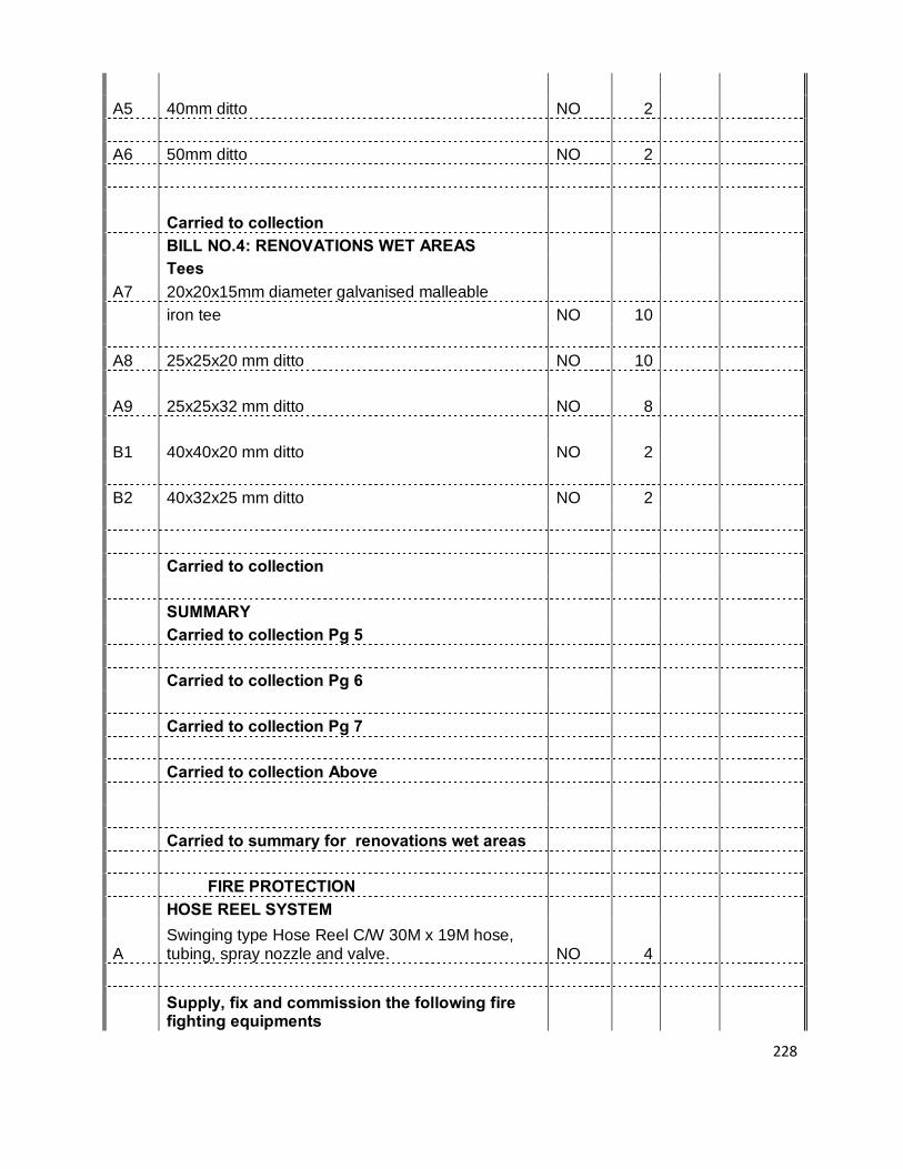
228
A5 40mm ditto NO 2 A6 50mm ditto NO 2 Carried to collection BILL NO.4: RENOVATIONS WET AREAS Tees A7 20x20x15mm diameter galvanised malleable iron tee NO 10 A8 25x25x20 mm ditto NO 10 A9 25x25x32 mm ditto NO 8 B1 40x40x20 mm ditto NO 2 B2 40x32x25 mm ditto NO 2 Carried to collection SUMMARY Carried to collection Pg 5 Carried to collection Pg 6 Carried to collection Pg 7 Carried to collection Above Carried to summary for renovations wet areas FIRE PROTECTION HOSE REEL SYSTEM
A Swinging type Hose Reel C/W 30M x 19M hose, tubing, spray nozzle and valve. NO 4
Supply, fix and commission the following fire fighting equipments

229
B 9 lts water Co2 fire extinguisher portable NO 6 C 9 Kgs Dry powder Extinguisher portable NO 6 D 9lts CO2 extinguisher portable NO 6 Carried to summary for fire protection

230
ELECTRICAL WORKS
ITEM DESCRIPTION
UNITS
QTY
RATE
AMOUNT
A
Supply install and connect 32 Amp TP/N isolator for fire/water booster/sump pumps supply as specified NO 1
B Supply,install and connect 10.0 sq.mm x3 core PVC SWA PVC cable LM 150
C
Supply,install and connect-up complete 12 way 100 Amp TP/N distribution board complete with all MCBs NO 2
D
300mm x 50mm x3-compartment powder coated sheet steel skirting trunking including all brackets,bends,screws,covers,etc as per the technical submitted for approval prior to procurement specification.Sample to be CLIP-ON LM 350
E
300mm x 25mm galvanised sheet steel covered cable tray including all brackets,bends,screws covers,etc as per the technical specification LM 60
F
Supply,install and connect complete 5x 2.5 sq. mm colour coded SC cables to lighting and socket points drawn in trunking and PVC conduits. LM 500
G
Supply and install 600 x 600mm light fittings complete with 4 No. 2fts bulbs and all necessary accessories. NO 100
Carried to collection Supply,install and connect-lighting switches with associated concealed conduits H (a) 1 gang 1 way NO 10 I (b) 1 gang 2 way NO 5 J (c ) 2 gang 2 way NO 15

231
K (d) 3 gang 2 way NO 5 L (e) 1 gang intermediate switch NO 5 M (f) 3 gang intermediate switch NO 5
N
Supply,install and connect-13 Amp twin socket outlet point complete with all accessories necessary for flush mounting NO 50
O Supply,install and connect telephone outlet box as per specifications NO 50
P Ditto item E/10 but computer data outlet box NO 50
Q Supply and install fused connection unit,flush with neon indicator for hand dryer. NO 10
R Supply and install 20A DP switch,flush with neon indicator for air conditioning unit NO 8
S Allow for the testing and commissioning of the raw power installations ITEM 1
Carried to summary for electrical Works

232
GRAND SUMMARY ITEM NO DESCRIPTION AMOUNT
A PRELIMINARIES - B SECOND FLOOR - C WET AREAS - D ELECTRICAL WORKS & ICT WORKS - E SUBTOTAL 1 - F ADD 7.5% CONTIGENCIES - G SUBTOTAL 2 - H ADD 16% VAT - I TOTAL -
TOTAL AMOUNT VAT INCLUSIVE Carried to Form of Tender -