
Telephone-related ASCII Schematics V1 · 2010-07-29 · The bottom comparator section has its...
27
Some of the schematics for PHONE-IN-USE indicators have been confirmed to be defective or plain useless. I will upload a corrected version in the near future. Until then, use CAUTION! This one has been confirmed to work and work well. Telephone-related ASCII Schematics V1.01 Contents: 1. Telephone in use light ● 2. Detecting a telephone RING ● 3. (manual) Phone In-Use Light ● 4. Phone to audio interface (SSI202 input) ● 5. Phone Off-Hook Indicator ● 6. 'phone rang' indicator light ● 7. Phone Line to Audio ● 8. Phone in-use ● 9. Telephone Line Monitor (Plans) ● 10. Use old phones as an intercom ● 11. Phone-In-Use indicator ● 12. Telephone Power? ● 13. Hold function for Telephone ● 14. Digital/Standard Phone Line Tester ● [Document Version: 1.00] [Last Updated: 12/12/96] 1. Telephone in use light From: [email protected] (Dave Thomas) +----+-------------+-------+-------- +9VDC | | | | | | |\ R5 R6 | +-------|-\ | | | | | >--+ LED1 | | +--|+/ | v ^ | | |/ | | CR2 R4 | | C+ | | | |\ | | / <+>--R1--+--R3--+----+--> | <--+--|-\ | |/ | | | | | >--+-B-| phone | | | +-------|+/ |\ Sci.electronics FAQ: Telephone ASCII Schematics http://www.repairfaq.org/ELE/F_ASCII_Schem_Tel.html (1 of 15) [8/31/2004 9:16:37 PM]
Transcript of Telephone-related ASCII Schematics V1 · 2010-07-29 · The bottom comparator section has its...

Some of the schematics for PHONE-IN-USE indicators have been confirmed to be defective or plain useless.I will upload a corrected version in the near future. Until then, use CAUTION!
This one has been confirmed to work and work well.
Telephone-related ASCII Schematics V1.01Contents:
1. Telephone in use light●
2. Detecting a telephone RING●
3. (manual) Phone In-Use Light●
4. Phone to audio interface (SSI202 input)●
5. Phone Off-Hook Indicator●
6. 'phone rang' indicator light●
7. Phone Line to Audio●
8. Phone in-use●
9. Telephone Line Monitor (Plans)●
10. Use old phones as an intercom●
11. Phone-In-Use indicator●
12. Telephone Power?●
13. Hold function for Telephone●
14. Digital/Standard Phone Line Tester●
[Document Version: 1.00] [Last Updated: 12/12/96]
1. Telephone in use lightFrom: [email protected] (Dave Thomas)
+----+-------------+-------+-------- +9VDC | | | | | | |\ R5 R6 | +-------|-\ | | | | | >--+ LED1 | | +--|+/ | v ^ | | |/ | | CR2 R4 | | C+ | | | |\ | | /<+>--R1--+--R3--+----+--> | <--+--|-\ | |/ | | | | | >--+-B-|phone | | | +-------|+/ |\
Sci.electronics FAQ: Telephone ASCII Schematics
http://www.repairfaq.org/ELE/F_ASCII_Schem_Tel.html (1 of 15) [8/31/2004 9:16:37 PM]
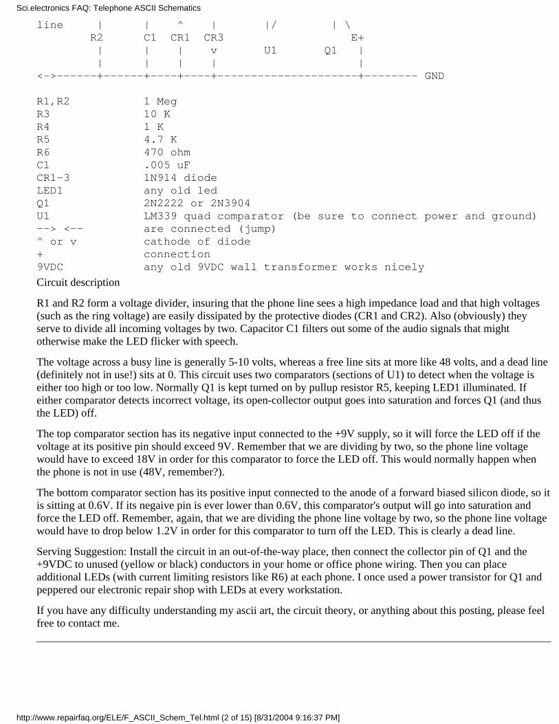
line | | ^ | |/ | \ R2 C1 CR1 CR3 E+ | | | v U1 Q1 | | | | | |<->------+------+----+----+---------------------+-------- GND R1,R2 1 MegR3 10 KR4 1 KR5 4.7 KR6 470 ohmC1 .005 uFCR1-3 1N914 diodeLED1 any old ledQ1 2N2222 or 2N3904U1 LM339 quad comparator (be sure to connect power and ground)--> <-- are connected (jump)^ or v cathode of diode+ connection9VDC any old 9VDC wall transformer works nicely
Circuit description
R1 and R2 form a voltage divider, insuring that the phone line sees a high impedance load and that high voltages(such as the ring voltage) are easily dissipated by the protective diodes (CR1 and CR2). Also (obviously) theyserve to divide all incoming voltages by two. Capacitor C1 filters out some of the audio signals that mightotherwise make the LED flicker with speech.
The voltage across a busy line is generally 5-10 volts, whereas a free line sits at more like 48 volts, and a dead line(definitely not in use!) sits at 0. This circuit uses two comparators (sections of U1) to detect when the voltage iseither too high or too low. Normally Q1 is kept turned on by pullup resistor R5, keeping LED1 illuminated. Ifeither comparator detects incorrect voltage, its open-collector output goes into saturation and forces Q1 (and thusthe LED) off.
The top comparator section has its negative input connected to the +9V supply, so it will force the LED off if thevoltage at its positive pin should exceed 9V. Remember that we are dividing by two, so the phone line voltagewould have to exceed 18V in order for this comparator to force the LED off. This would normally happen whenthe phone is not in use (48V, remember?).
The bottom comparator section has its positive input connected to the anode of a forward biased silicon diode, so itis sitting at 0.6V. If its negaive pin is ever lower than 0.6V, this comparator's output will go into saturation andforce the LED off. Remember, again, that we are dividing the phone line voltage by two, so the phone line voltagewould have to drop below 1.2V in order for this comparator to turn off the LED. This is clearly a dead line.
Serving Suggestion: Install the circuit in an out-of-the-way place, then connect the collector pin of Q1 and the+9VDC to unused (yellow or black) conductors in your home or office phone wiring. Then you can placeadditional LEDs (with current limiting resistors like R6) at each phone. I once used a power transistor for Q1 andpeppered our electronic repair shop with LEDs at every workstation.
If you have any difficulty understanding my ascii art, the circuit theory, or anything about this posting, please feelfree to contact me.
Sci.electronics FAQ: Telephone ASCII Schematics
http://www.repairfaq.org/ELE/F_ASCII_Schem_Tel.html (2 of 15) [8/31/2004 9:16:37 PM]
2. Detecting a telephone RINGFrom: [email protected] (Dave Thomas)
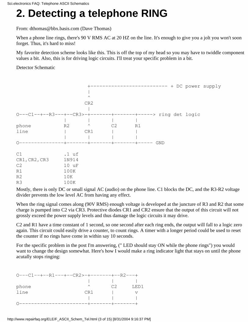
When a phone line rings, there's 90 V RMS AC at 20 HZ on the line. It's enough to give you a jolt you won't soonforget. Thus, it's hard to miss!
My favorite detection scheme looks like this. This is off the top of my head so you may have to twiddle componentvalues a bit. Also, this is for driving logic circuits. I'll treat your specific problem in a bit.
Detector Schematic
+-------------------------- + DC power supply | ^ CR2 |O---C1--+--R3---+--CR3>-+-------+-------+-----> ring det logic | | | |phone R2 ^ C2 R1line | CR1 | | | | | |O---------------+-------+-------+-------+----- GND C1 .1 ufCR1,CR2,CR3 1N914C2 10 uFR1 100KR2 10KR3 100K
Mostly, there is only DC or small signal AC (audio) on the phone line. C1 blocks the DC, and the R3-R2 voltagedivider prevents the low level AC from having any effect.
When the ring signal comes along (90V RMS) enough voltage is developed at the juncture of R3 and R2 that somecharge is pumped into C2 via CR3. Protective diodes CR1 and CR2 ensure that the output of this circuit will notgrossly exceed the power supply levels and thus damage the logic circuits it may drive.
C2 and R1 have a time constant of 1 second, so one second after each ring ends, the output will fall to a logic zeroagain. This circuit could easily drive a counter, to count rings. A timer with a longer period could be used to resetthe counter if no rings have come in within say 10 seconds.
For the specific problem in the post I'm answering, (" LED should stay ON while the phone rings") you wouldwant to change the design somewhat. Here's how I would make a ring indicator light that stays on until the phoneacutally stops ringing:
O---C1--+--R1---+--CR2>-+-------+--R2---+ | | |phone ^ C2 LED1line CR1 | v | | |O-----------------------+-------+-------+
Sci.electronics FAQ: Telephone ASCII Schematics
http://www.repairfaq.org/ELE/F_ASCII_Schem_Tel.html (3 of 15) [8/31/2004 9:16:37 PM]

C1 1 uF, decent voltageC2 see textR1 10 KCR2 1N914CR1 zener -- 9v or higherR2 1 KLED1 any old LED
I haven't built this, but here's my theory: C1 blocks DC, R1 limits the current that the ring voltage could cause. Thering voltage is rectified by CR2, filtered by C2, and limited in amplitude by zener CR1. Then the charge stored inC2 is slowly used to light LED1. As long as C2 is large enough (I'd start with 10 uF and experiment from there) tokeep the LED on between rings, and small enough that the LED goes off within a reasonable amount of time afterthe last ring, you're set.
(From no-idea)
I took ideas from schematics posted here a few days ago and constructed a telephone "line in use" indicator. Here'sthe circuit...
----> (to +5) 1M 1k / E >----- -----\/\/\----+---\/\/\-----| | \ C \ | / 220k \from \ / 1kphone bridge | \line | | | LED | | >------ --------------+---------------+ | GND
The transistor is a PNP Motorola 3638 with hFE of around 100 (probably doesn't matter). Also, you could use thiswith different supply voltages if you change the 220k resistor.
Also, in case anybody's interested, I found the on-hook open-circuit voltage of my phone line to be 48.7V, and theshort circuit current to be 72.8mA. This leads to the conclusion that the line has a resistance of about 670 ohms.There have been a few calls recently in sci.electronics for phone in use circuits (ie a circuit that lights a LED whenan extension phone is off hook).
Following are two circuits I archived some time ago from sci.electronics. The first appears pretty complete andrequires an external 5V power supply. The second seems to be a loop current trap that enables you to move fromone extension phone to another without leaving the first phone off hook. I don't know how well either of thesecircuits work as I haven't actually built them.
(From no-idea)
I thought I would try to post the schematic. This circuit requires a separate 5 volt supply. The branch of the circuitthat contains C1, C2 & R5, R6 is only used as a passive tap. (So you can record the line when the rest of the circuitsays 'off hook'. It can be removed if not needed. If used, it can directly drive a microphone input to a portablerecoreder.
Sci.electronics FAQ: Telephone ASCII Schematics
http://www.repairfaq.org/ELE/F_ASCII_Schem_Tel.html (4 of 15) [8/31/2004 9:16:37 PM]
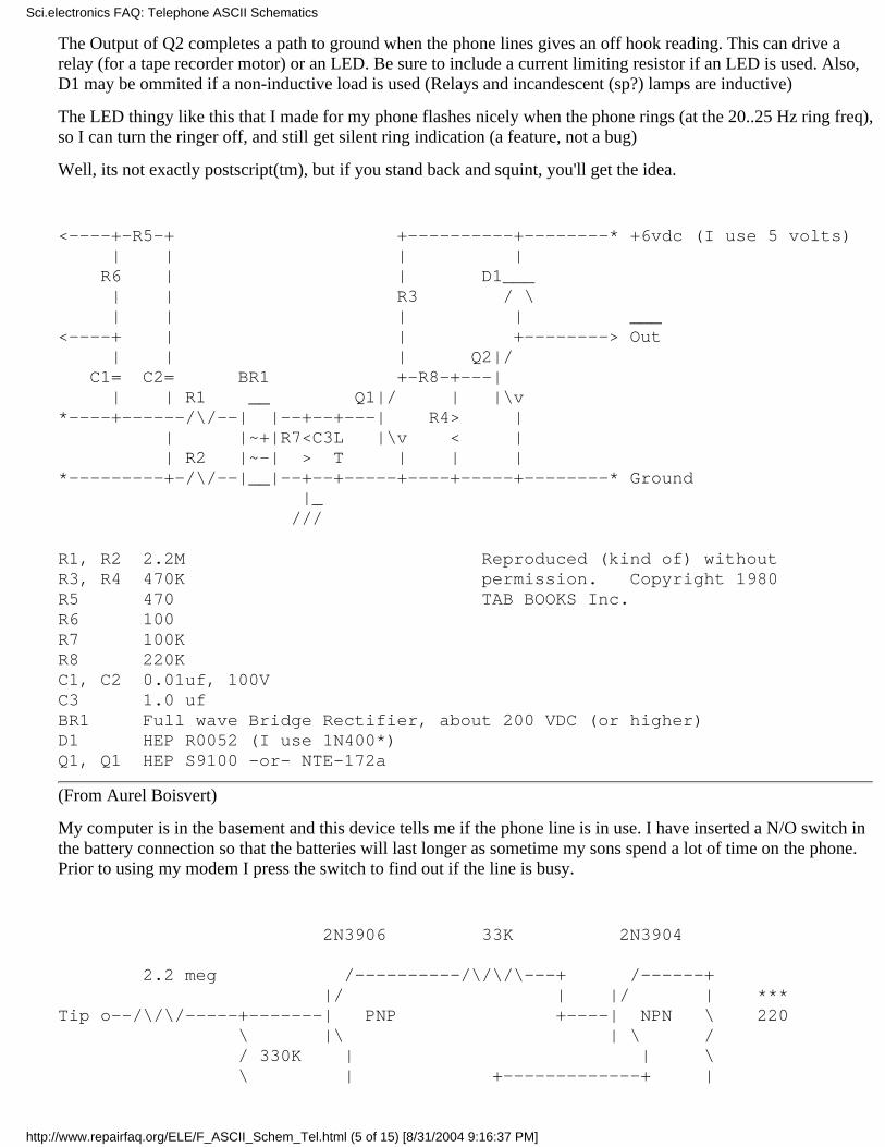
The Output of Q2 completes a path to ground when the phone lines gives an off hook reading. This can drive arelay (for a tape recorder motor) or an LED. Be sure to include a current limiting resistor if an LED is used. Also,D1 may be ommited if a non-inductive load is used (Relays and incandescent (sp?) lamps are inductive)
The LED thingy like this that I made for my phone flashes nicely when the phone rings (at the 20..25 Hz ring freq),so I can turn the ringer off, and still get silent ring indication (a feature, not a bug)
Well, its not exactly postscript(tm), but if you stand back and squint, you'll get the idea.
<----+-R5-+ +----------+--------* +6vdc (I use 5 volts) | | | | R6 | | D1___ | | R3 / \ | | | | ___<----+ | | +--------> Out | | | Q2|/ C1= C2= BR1 +-R8-+---| | | R1 __ Q1|/ | |\v*----+------/\/--| |--+--+---| R4> | | |~+|R7<C3L |\v < | | R2 |~-| > T | | |*---------+-/\/--|__|--+--+-----+----+-----+--------* Ground |_ /// R1, R2 2.2M Reproduced (kind of) withoutR3, R4 470K permission. Copyright 1980R5 470 TAB BOOKS Inc.R6 100R7 100KR8 220KC1, C2 0.01uf, 100VC3 1.0 ufBR1 Full wave Bridge Rectifier, about 200 VDC (or higher)D1 HEP R0052 (I use 1N400*)Q1, Q1 HEP S9100 -or- NTE-172a
(From Aurel Boisvert)
My computer is in the basement and this device tells me if the phone line is in use. I have inserted a N/O switch inthe battery connection so that the batteries will last longer as sometime my sons spend a lot of time on the phone.Prior to using my modem I press the switch to find out if the line is busy.
2N3906 33K 2N3904
2.2 meg /----------/\/\/\---+ /------+ |/ | |/ | ***Tip o--/\/\/-----+-------| PNP +----| NPN \ 220 \ |\ | \ / / 330K | | \ \ | +-------------+ |
Sci.electronics FAQ: Telephone ASCII Schematics
http://www.repairfaq.org/ELE/F_ASCII_Schem_Tel.html (5 of 15) [8/31/2004 9:16:37 PM]
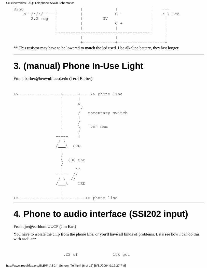
Ring | | | | --- o--/\/\/-----+ | O - | / \ Led 2.2 meg | | 3V | | | | O + | | | | | | | +-------------------------------------+ | | | | +-------------+-------------------+
** This resistor may have to be lowered to match the led used. Use alkaline battery, they last longer.
3. (manual) Phone In-Use LightFrom: [email protected] (Terri Barber)
>>-----------------+------+---->> phone line | | | o | / | / momentary switch | | | / | \ 1200 Ohm | / -----____| / \ /___\ SCR | / \ 600 Ohm / | ^^ ----- // / \ // /___\ LED | |>>-----------------+--------->> phone line
4. Phone to audio interface (SSI202 input)From: [email protected] (Jim Earl)
You have to isolate the chip from the phone line, or you'll have all kinds of problems. Let's see how I can do thiswith ascii art:
.22 uf 10k pot
Sci.electronics FAQ: Telephone ASCII Schematics
http://www.repairfaq.org/ELE/F_ASCII_Schem_Tel.html (6 of 15) [8/31/2004 9:16:37 PM]

400v ||(----------->Phone line tip o-----)(----)||( <---o to SSI202 input )||( >Phone line ring o-----------)||(-----------o---o ground
The transformer is a 600-ohm to 600-ohm line transformer. I use the circuit as-is, and works fine. Doesn't take thephone off hook, you'll need to add some circuitry for that. To set the pot, turn it down all the way, (for minimumaudio into the decoder) then hold down a tone on the phone while you slowly advance the pot up until the VALIDDIGIT line changes on the chip. Then advance the pot a little past that point. That should do it.
Also, it might not be a bad idea to put a couple of diodes back-to-back across the secondary of the transformer. I'mnot sure if enough voltage will be generated to harm the SSI chip when the phone rings or not. Mine has never hada problem, but it might be worth the cost of the two diodes for good luck.
5. Phone Off-Hook IndicatorAuthor: Roger Petersen Created: June 1985 or so Overview - What is it?
Runs off 9V battery, Plugs into phone jack, Lights an LED when any phone on the line is off-hook.
Phone Information
Measuring the voltage across the telephone line shows (typical numbers):
On Hook: 40 to 50 VDC Off Hook: 4 to 6 VDC Ringing: 100 VAC
The "standard" impedence of a telephone, when off-hook, is 680 ohms. Hanging a 680 ohm resistor across thetelephone line will drop the voltage from 48V to about 5V, causing the line to go "active". This is how HOLDswitches work. This probably means that it is bad to load down the phone line when the phone is off hook. Iwouldn't want to hang less than a 100Kohm load across it. Should probably measure this, and see how it affects theon-hook voltage.
I haven't seen any official documentation on these numbers. They're empirically derived.
The next question is: What are these voltages referenced to? If anything? It's possible that the most positive phonewire is tied to the GND in your house, or else maybe the neutral wire in your 120VAC outlet. So measuring thephone line voltages with respect to your household GND should show 0V and -48V when the phone is on-hook.But I don't know. It's probably best to not rely on this behavior.
Circuit Design - Off-hook Indicator
Could probably use some sort of transistor design, but I'm a digital weenie.
I used a CMOS 4049 Hex Interter. This part (supposedly) has high drive output. And since it's CMOS, it canoperate with Vcc from +3 to +15V. And it has a high input impedence.
+9V |Phone+ -----+ |+ | LED
Sci.electronics FAQ: Telephone ASCII Schematics
http://www.repairfaq.org/ELE/F_ASCII_Schem_Tel.html (7 of 15) [8/31/2004 9:16:37 PM]
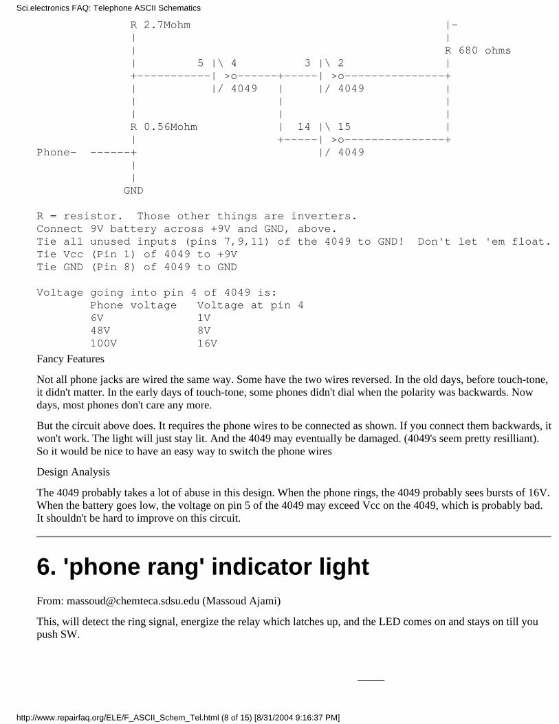
R 2.7Mohm |- | | | R 680 ohms | 5 |\ 4 3 |\ 2 | +-----------| >o------+-----| >o---------------+ | |/ 4049 | |/ 4049 | | | | | | | R 0.56Mohm | 14 |\ 15 | | +-----| >o---------------+Phone- ------+ |/ 4049 | | GND
R = resistor. Those other things are inverters.Connect 9V battery across +9V and GND, above.Tie all unused inputs (pins 7,9,11) of the 4049 to GND! Don't let 'em float.Tie Vcc (Pin 1) of 4049 to +9VTie GND (Pin 8) of 4049 to GND Voltage going into pin 4 of 4049 is: Phone voltage Voltage at pin 4 6V 1V 48V 8V 100V 16V
Fancy Features
Not all phone jacks are wired the same way. Some have the two wires reversed. In the old days, before touch-tone,it didn't matter. In the early days of touch-tone, some phones didn't dial when the polarity was backwards. Nowdays, most phones don't care any more.
But the circuit above does. It requires the phone wires to be connected as shown. If you connect them backwards, itwon't work. The light will just stay lit. And the 4049 may eventually be damaged. (4049's seem pretty resilliant).So it would be nice to have an easy way to switch the phone wires
Design Analysis
The 4049 probably takes a lot of abuse in this design. When the phone rings, the 4049 probably sees bursts of 16V.When the battery goes low, the voltage on pin 5 of the 4049 may exceed Vcc on the 4049, which is probably bad.It shouldn't be hard to improve on this circuit.
6. 'phone rang' indicator lightFrom: [email protected] (Massoud Ajami)
This, will detect the ring signal, energize the relay which latches up, and the LED comes on and stays on till youpush SW.
____
Sci.electronics FAQ: Telephone ASCII Schematics
http://www.repairfaq.org/ELE/F_ASCII_Schem_Tel.html (8 of 15) [8/31/2004 9:16:37 PM]
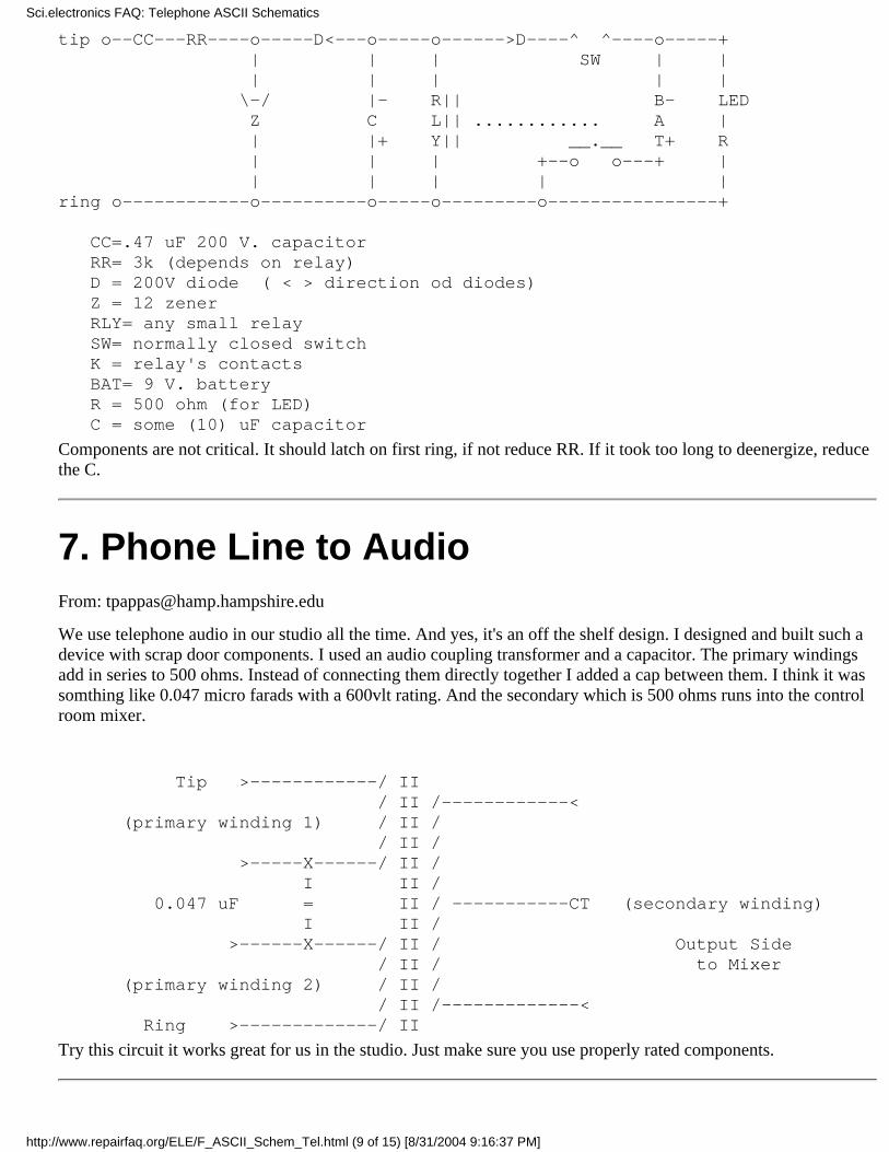
tip o--CC---RR----o-----D<---o-----o------>D----^ ^----o-----+ | | | SW | | | | | | | \-/ |- R|| B- LED Z C L|| ............ A | | |+ Y|| __.__ T+ R | | | +--o o---+ | | | | | |ring o------------o----------o-----o---------o----------------+
CC=.47 uF 200 V. capacitor RR= 3k (depends on relay) D = 200V diode ( < > direction od diodes) Z = 12 zener RLY= any small relay SW= normally closed switch K = relay's contacts BAT= 9 V. battery R = 500 ohm (for LED) C = some (10) uF capacitor
Components are not critical. It should latch on first ring, if not reduce RR. If it took too long to deenergize, reducethe C.
7. Phone Line to AudioFrom: [email protected]
We use telephone audio in our studio all the time. And yes, it's an off the shelf design. I designed and built such adevice with scrap door components. I used an audio coupling transformer and a capacitor. The primary windingsadd in series to 500 ohms. Instead of connecting them directly together I added a cap between them. I think it wassomthing like 0.047 micro farads with a 600vlt rating. And the secondary which is 500 ohms runs into the controlroom mixer.
Tip >------------/ II / II /------------< (primary winding 1) / II / / II / >-----X------/ II / I II / 0.047 uF = II / -----------CT (secondary winding) I II / >------X------/ II / Output Side / II / to Mixer (primary winding 2) / II / / II /-------------< Ring >-------------/ II
Try this circuit it works great for us in the studio. Just make sure you use properly rated components.
Sci.electronics FAQ: Telephone ASCII Schematics
http://www.repairfaq.org/ELE/F_ASCII_Schem_Tel.html (9 of 15) [8/31/2004 9:16:37 PM]

8. Phone in-useFrom: [email protected] (Kenneth Carver)
The circuit I built gives a visual indication at each extension when any extension is off-hook. It is line-powered,and the maximum number that can be used on our system is three. Since they all draw power at the same time tolight the LEDs, any more indicators would cause an off-hook condition. Some changes could be made to reducethe current draw, to allow using more indicators, but the brightness of each led would suffer. The LEDs I used aretiny, but amazingly bright on just a couple milliamps. I picked them up from a surplus catalog, I can't rememberwhich one. If you were to use battery power for the circuit, you could use almost any number of indicators. I haduse only for three, and I did not want to worry about replacing batteries. If I remember correctly, our pbx requireda load of about 20 milliamps before the line failed to hang up. This circuit draws about 5 milliamps when off-hook, much less when on-hook. It senses the drop in line voltage from about 46 volts to 6 volts when an extensionis picked up. The zener voltage should be well above the off-hook voltage of your system, and well below theon-hook voltage. The transistors are small high-voltage npn types I had on hand. The LED also flashes with thering voltage. Putting a suitable MOV across the line is a good precaution to prevent lightning damage.
(+)------------+---------------+--------------------------+ green | | | / / / \ 2200 \ 100K 100K \ / / /1N4148 \ \ \ +---------+ | | ___|___ ___|___ | ___|___/ / \ \ / LED | 10V / / \ /_____\ __\ /__ | ZENER /_____\ | | | | +---------+ | | | c | | \ | | | MPSA42 \|-----------+------------- c | /| ___|___ \ | | / | / \ MPSA42 \|--------+ | e /_____\ /| ___|___ | 1N4148 | / | / \ | | | e /_____\ | | | |(-)------------+---------------+-------------+------------+red 1N4148
Sci.electronics FAQ: Telephone ASCII Schematics
http://www.repairfaq.org/ELE/F_ASCII_Schem_Tel.html (10 of 15) [8/31/2004 9:16:37 PM]

9. Telephone Line Monitor (Plans)From: [email protected] (while you were out)
Get yourself a low-voltage DC relay, like a 3v relay... Set it up as follows:
Audio Isolation Transformer To <--)||(---------------------+ )||( | <==== Relay Contacts Speaker <--)||(---+ +--------o/ o 600ohm | | mmmmm DC 3v Relay Coil | | | | RED -----------|----+-------+ +----------> To Dispatcher's Phone | GREEN -----------+-----------------------------> To Dispatcher's Phone | | -+- indicates a connection, --- is not connected. | |
You may have to use a Diode or two to make this telephone-line FCC clean... I'm not saying this is a clean circuitat all. It's cheap and dirty! You may have to use a Op-Amp (Use an LM386, they're good for speakers) on thespeaker. Depends. Experiment!
Circuit Theory:
When the Dispatcher picks up the phone (in a standard circuit, I have NO clue what your PBX does.. this will workon standard home phones, and I used to use it for a tape-recording controller) Hey, there's an Idea - spend $25 on atelephone recording device, and hitch it to a nice loud amp and speaker combo, instead of a tape deck. It'll saveyou loads of time...
Anyhow.. the voltage will turn into DC, approx 6-10VDC when the phone is picked up, (which is why you've gottaput it before the dispatcher's phone) and click the relay. The relay will connect the transformer, and feed thespeaker. it might be towards your advantage to use a SPDT relay, and connect BOTH ends of the transformer, andnot just switch one end in and out. That might prevent some line noise...
10. Use old phones as an intercomFrom: [email protected] (Markus Wandel)
I have recently thought about this and come up with a kludgy but workable scheme.
Talking over the phones is easy. You put DC current through the phone and it transmits and receives audio. So twophones and a current source (about 25mA) all in series will give you a talking circuit. A suitable current source canbe as simple as a 9V battery and a series resistor whose value is adjusted (with both phones offhook) till about25mA flows. You can then bypass the battery and the resistor with a capacitor to couple the audio straight acrossand get a loud and clear connection.
What is much harder is signaling the other end. To ring the bell you need to put 90V (RMS) 20Hz AC into thephone (nominally). Lower voltages will work (down to about 40V) but different frequencies won't. You can't ring
Sci.electronics FAQ: Telephone ASCII Schematics
http://www.repairfaq.org/ELE/F_ASCII_Schem_Tel.html (11 of 15) [8/31/2004 9:16:37 PM]

the phone at 60Hz. I have a ringing circuit in a PBX I built but it consists of a 20Hz sinewave generator, apush-pull power booster and a big transformer. Much too elaborate for a simple 2-phone intercom circuit, andanyway the ringing voltage could painfully zap a kid.
So forget the bell and look into other forms of signaling. This is what I have come up with:
+ | | - +-------+------ - - --+---||||---/\/\/--+---- - -----+-------+ | | | | | R | | | | | | 24V | | | | --- | | --- | | | | +---||------------+ | | | | --- Sonalert C Sonalert --- | | C | | C | +---||--+ +--||---+ | _|_, _|_ | | / \ 15V 15V \ / | PHONE -+- Zener Zener `-+- PHONE | | | | | | | | +-------+------------------ - - - -------------------+-------+
As before, set R to give you a talking current (both phones offhook) of about 25mA. Start with 1K ohm. Leave it inif the phones work well enough; the current is not very critical. The capacitors C are audio bypass capacitors andshould be about 0.47uF.
When the phones are onhook they present an open circuit, and the 24V battery voltage is not enough to overcomethe 30V series drop of the Zeners and no current flows. When both phones are offhook they present a very lowresistance and the talking current (determined by R) flows.
When only one phone is offhook it places its low DC resistance across the Zener diode on its side so that the full24V supply is applied to the other side. This overcomes the voltage drop of the other Zener diode so the otherSonalert beeps. The wonderful thing about Sonalerts is that they make a loud noise with only a few milliamps ofcurrent so the series resistor R doesn't matter. Especially nice is a pulsing Sonalert which goes "Beep beep beep"automatically. While the far-end Sonalert is beeping, you hear the beeping in the near-end receiver (at low volumethanks to the bypass capacitor across the far-end Sonalert) to confirm that the line is working and the other end isbeing signaled.
The power supply can be three 9V batteries in series but since 80% of the power is lost in series resistor R ratherthan in powering the phones it seems a little wasteful. A 24V wall wart with clean filtering would be better.
The signaling components can be mounted inside the phones. Only two wires are needed to go to each phone, andthe power supply can be mounted centrally, out of harm's way. If R is adequately big (1/2 watt) and has enoughventilation then both lines can be indefinitely shorted out without any fire hazard and there is not enough voltageanywhere to hurt anyone.
I have tested this with 500-type phones and two different types of piezo buzzers (pulsing sonalerts and non-pulsingbrand X ones) and it works great. You should be able to get all the needed parts including piezo buzzers at RadioShack. I love telephones. Too bad I don't have any kids who want an intercom line.
Sci.electronics FAQ: Telephone ASCII Schematics
http://www.repairfaq.org/ELE/F_ASCII_Schem_Tel.html (12 of 15) [8/31/2004 9:16:37 PM]

11. Phone-In-Use indicatorFrom: [email protected] (richard steven walz)
------+-------------+-------------+----------- pos (tip) | | | | | --- | | R3 | | | | | | | | --- zener | | | /------/ --- ----- / \ R2 | | \ / LED ------ | | ----- | --- | | | | | --------+----+ ---+ | |/ | |/ +---| npn1 +---| npn2 | |\ |\ --- -+ -+ R1 | | | | | | | | --- | | | | | ------+------+------------------+-------------- neg (ring)
Now here's some logic that should work fine with the right zener and the right resistors and a couple of cheap npn's2n2222A's or 2n3904's (06's?). If you get close to 25 volts with the new smart test boxes, a 20 volt Z may workfine. Choose R1 to limit current through Z and have enough left to turn on npn1 just enough to deprive npn2,choose R2 for that, and you will need to add a resistor R3 to protect the LED from overcurrent as needed,depending on the phone system you have!
You MIGHT need a resistor between the bottom of R2 and the base of npn2 to get it right, but I don't think sobecause of the B-E 0.7 volt diode junction voltage needed in npn2 to get it out of cutoff.
12. Telephone Power?From: [email protected] (Henry Spencer)
" If one were to try [using power from phone line], would phone company had a way of finding out?"
Most assuredly. They aren't in the business of supplying power, and they ARE in the business of finding faults intheir lines. Any substantial power drain from their lines WILL be detected. If it's large, the phone switch willconclude that you've dropped the phone in the bathtub or something like that, and will disconnect your line (andwill check periodically to see if the drain has gone away and you can be reconnected). If it's small, the switch willreport it to the service people as a possible line problem, to be investigated before it causes a complete failure...and if they investigate and find that you're to blame, they will probably send you a bill for time and trouble. Thecurrent you can draw without eventually having it noticed is very small.
Sci.electronics FAQ: Telephone ASCII Schematics
http://www.repairfaq.org/ELE/F_ASCII_Schem_Tel.html (13 of 15) [8/31/2004 9:16:37 PM]

13. Hold function for TelephoneFrom: [email protected] (.)
Here's the schematic that was in the November 1992 issue of Electronics Now. (Nobody sue me)
+-------+------+ R1 = 2.2K | | | R2 = 1 K-| SW R | R3 = 47 ohms | 1 | SCR = 2N5064, TIC47, or MCR104 | | | R LED | Well, that's it, just remember that 2 | | the cathode of both the SCR and the | | +----- RING (Red) LED are towards the bottom. +------SCR | | +----- TIP (Green) R | | 3 | | | | | +-------+------+
14. Digital/Standard Phone Line Tester(From Dan Ts'o)
Radio Shack sells a similar device without the high current function. It detects one or two lines on an RJ-11 andtells you its polarity. It costs $6. The schematic is:
o-------+----------+ | | \ | Line 1 /680 \ / red/green LED \ .5W --- | | o-------+----------+
The circuit for Line 2 is identical. Note that each red/green LED comes standard as reverse wired (red LED"forward", green LED "reversed).
Based on the above, I think an appropriate modification to include a high current indicator would be: (I've tested it)
20 o--+-\/\/\/--+-----------+----------+ | | | | | | \ --- +--->|----+ / / \ red/green LED
Sci.electronics FAQ: Telephone ASCII Schematics
http://www.repairfaq.org/ELE/F_ASCII_Schem_Tel.html (14 of 15) [8/31/2004 9:16:37 PM]

red/green \ 680 | LED | .5W | o------------------------+----------+
You can adjust the 20ohm resistor value to set what is considered "high current". 20ohms lights the LED at around90ma. Total parts costs under $4, or if you use Radio Shack's $6 line tester and add the above resistor and LED,then under $7. (I'm not faulting IBM for charging $30).
This whole issue really bothers me because it means that I can't bring a PCMCIA modem with me on trips andcount on it working at any given hotel. That means I should carry around my pocket modem just in case. So thenwhat's the point of having the PCMCIA modem!
Please see document for document author. | [mailto]. The most recent version is available on theWWW server http://www.repairfaq.org/ [Copyright] [Disclaimer]
Sci.electronics FAQ: Telephone ASCII Schematics
http://www.repairfaq.org/ELE/F_ASCII_Schem_Tel.html (15 of 15) [8/31/2004 9:16:37 PM]
*************
NOTICE: OUR ISP IS MIGRATING TONEW SERVERS - YOU MAY
ENCOUNTER SOME PROBLEMS.pLEASE REPORT ANYTHING AMISS
TO US USING AND WE WILLTRY TO RESOLVED IT ASAP. SORRY
ABOUT THE TROUBLES!
*************
Sci.Electronics.Repair FAQ Email links
(including Sam's Laser FAQ)
Version: 2.12 (Last Updated: 10/29/02)
Samuel M. Goldwasser
Author of 99% of the consumer electronics and appliance repair guides, related testing andinformation documents, assorted schematics, and Sam's Laser FAQ.
Home URL: http://www.repairfaq.org/sam/
Important Notes:Please make an attempt to use the resources at this site to solve your problems. If it isobvious that you have not even looked in the FAQs, you will be (reasonably) politelydirected to do so. I won't ignore pleas for help but doing some research first will resultin a much better chance of useful assistance.
❍
●
Sci.Electronics.Repair FAQ Email Links
http://www.repairfaq.org/F_email.html (1 of 3) [8/31/2004 9:17:02 PM]
In particular, if you have a consumer electronics repair question for a specific modelof something, ask it on the USENET newsgroup sci.electronics.repair (see below ifyou don't know what this means) - I DO NOT have access to service manuals orschematics. You are wasting your time and mine asking me about R342 for aHypertron model XQR143 because I don't have a clue about it. :)
❍
While I welcome laser related questions (and contributions of all types) there is anexcellent chance that most of your basic questions (and a whole lot more) are alreadyaddressed in the FAQ.
❍
I NEVER send email attachments. If you receive a message supposedly from one ofmy addresses with any sort of attachment, it is bogus and possibly a virus. Someone'saddress book has my address and their computer is now infected. Send me thecomplete headers and I'll attempt to check it out, or just delete it.
❍
I don't use ICQ, Instant Messenger, On-Line Chat, or anything similar or I'd never getanything productive accomplished. Sorry, email via the feedback form will have todo. My apologies for not including an actual email address but the volume of SPAMhas finally become unbearable.
❍
Having said all that, I do generally try to answer every email I receive which doesn'tappear to be SPAM. If you have asked a serious question and receive no reply fromme within a day or two, the most likely reason is that your return address is incorrector your SPAM filters are being overenthusiastic about deleting what they think is junkemail.
❍
Filip Gieszczykiewicz
WebAdmin, author/compiler of original Sci.Electronics FAQ, packaging/wrapping of Sam'sbooks.
Home URL: http://www.repairfaq.org/filipg/
Email: [email protected]
●
USENET newsgroup sci.electronics.repair
This public discussion forum is where model specific questions and general questions notaddressed by any of the FAQs should be asked. If the link below doesn't work, you willneed to ask your ISP or system administrator how to set up USENET newsgroup access. Or,you can read, search, and post using Google Groups. For more information on USENETnewsgroups, see the document: "Troubleshooting of Consumer Electronic Equipment" orthe chapter of Sam's Laser FAQ: "Laser Information Resources".
●
Sci.Electronics.Repair FAQ Email Links
http://www.repairfaq.org/F_email.html (2 of 3) [8/31/2004 9:17:02 PM]

URL: news:sci.electronics.repair
Sci.Electronics.Repair FAQ Email Links
http://www.repairfaq.org/F_email.html (3 of 3) [8/31/2004 9:17:02 PM]

Welcome to theSci.Electronics.Repair FAQ
Galactic Homepage
Welcome to the Sci.Electronics.Repair Frequently Asked Question(s) (or S.E.R FAQ for short) HomePage. This site features Samuel M. Goldwasser's latest and greatest "Notes on the Troubleshooting andRepair of..." series of comprehensive repair guides for consumer electronics equipment and otherhousehold devices. There is also a great deal of other information of interest to the electronics hobbyist,experimenter, technician, engineer, and possibly even the dentist and poet. Included are the now quitecomprehensive and massive "Sam's Laser FAQ", many new schematics, and links to over 1,000technology related sites. In addition, there are a variety of documents from other sources on electronicstroubleshooting, repair, and other related topics.
If you know of something that is incorrect or missing from this site or simply have comments, friendlycomplaints, requests, or additions, please make use of the absolutely and positively fabulous
or see the Email Page to identify the most appropriate recipient. Thanks!
Sci.Electronics.Repair FAQ Search on Drexel Mirror Site
The following provides a fast search facility but is currently only present on the S.E.R FAQ mirror site atDrexel University which is maintained up to date almost daily.
Search the entire Sci.Electronics.Repair FAQ for MoreSearch Options
Sci.Electronics.Repair FAQ: Home Page
http://www.repairfaq.org/ (1 of 4) [8/31/2004 9:17:03 PM]
Sci.Electronics.Repair FAQ SitesPlease check the Home and Mirror Site Locations page to identify the best site for your needs. This isimportant for several reasons:
Not all of these Web sites have the same collection of documents or the same versions of thesedocuments.
●
Accessing a site near your physical position on this planet (or elsewhere) should help to minimizeNet traffic and hopefully reduce your World Wide Wait. :-)
●
This will also help to distribute the load among the sites (excessive load was what caused ourformer RepairFAQ.org ISP to implode).
●
The link below takes you directly to the collection of formatted documents at this site. This is probablywhat you want:
Sci.Electronics.Repair FAQ Main Table of Contents (ToC) - Home (RepairFAQ.org)●
Sam's Laser FAQA major portion of the Sci.Electronics.Repair FAQ is the document: "LASERS: Safety, Info, Links, Parts,Types, Drive, Construction" which has a great deal of information on a variety of laser related topicsincluding a comprehensive treatment of diode, helium-neon, argon/krypton ion, and CO2 lasers as well asamateur laser construction including numerous examples of truly home-built lasers. Much of this is notavailable anywhere else either on-line or in print! Yes, I know what you are thinking: "I hadn't noticed thatany of my multitude of lasers were broken...", but so be it. :-)
Sam's Laser FAQ - A Practical Guide to Lasers for Experimenters and Hobbyists.●
This document is also available at many sites worldwide. As above, check the Home and Mirror SiteLocations page to identify the best site for your needs.
Silicon Sam's Technology Resource (SSTR)The SSTR documents are where my contributions to the S.E.R FAQ start out but the large repair guides ofthe "Notes on the Troubleshooting and Repair of...." series may not be as nicely formatted (i.e., once Filipgets through indexing and cross-referencing them). In general, additions to SSTR are minor. Therefore, thesolutions to your problems are likely to be accessible via the S.E.R FAQ pages - and in a much moreuser-friendly form! However, if you long for the thrill of dealing with raw ASCII (not even brain-deadHTML) or are desperate for bits that are hot off my computer's hard drive, check out:
Sci.Electronics.Repair FAQ: Home Page
http://www.repairfaq.org/ (2 of 4) [8/31/2004 9:17:03 PM]

Silicon Sam's Technology Resource - Comprehensive Repair Guides, Sam's Laser FAQ,
Schematics, etc.
●
This collection is also available at many sites worldwide. As above, check the Home and Mirror SiteLocations page to identify the best site for your needs.
Fil's World Wide Web - The Original!And, don't miss the original Sci.Electronics FAQ collection (needs some updating but don't we all - stilllots to see) and other valuable, informative, and interesting documents and links from Filip himself:
Fil's World Wide Web - Fil's Auto Corner, RC and other Fil stuff, what remains of the
Sci.Electronics FAQ, etc.
●
Please Read at Least OnceA word about the philosophy of this site: These pages are declared to be a fluff-free zone! There will be nounnecessary, superfluous, or useless graphics of any kind - including but not limited to: dancing, gyrating,or other animated icons, colored textured backgrounds that are impossible to read through, or forceddownloading of bit intense pictures that may be of no interest to you. Nor, will I ever expect you to use aparticular brand of Web browser to be able to effectively access these pages. There are and never will beany advertisements, cookies, or other impositions on your time and space. In the time that it may takewading through a single monstrosity of the professional Web page designers at other sites, you will be ableto find out what you want to know, when you want to know it! What a concept. :-) (Note, however, thatyour browser needs to be configured properly to make sense of the many ASCII diagrams, schematics, andtables. See the document: Suggested Browser Settings for font and other related information.)
In return for this gold mine of information, please make a serious effort to find the answers to yourquestions before contacting me. It may take just a wee bit of effort and could stress a few neurons in theprocess, but there is an excellent chance that what you seek is covered at these sites. Should you be reallystuck, I will respond to email in a timely manner. However, if your question indicates that you haven'teven gotten past the Main Menu, AND I am in a good mood, you will get a somewhat polite reply to readthe #$%& FAQs. On the other hand, if it is a bad day, and you are really really lucky, you will probably beignored. In any case, I expect to be able to hit the reply key for my mail program and not get bouncedemail. I will not attempt to unjumble any anti-SPAM email addresses! I have posted over 20,000 articles tothe USENET newsgroups using my true email address. (And, you won't pick up SPAM via private emailanyhow.) Yes, SPAM is a pain but I tolerate the small amount I get so others will not be inconvenienced.
Note: I NEVER send email attachments. If you receive a message supposedly from one of my addresseswith any sort of attachment, it is bogus and possibly a virus. Someone's address book includes my addressand their computer is infected. Send me the complete headers and I'll attempt to check it out, or just delete
Sci.Electronics.Repair FAQ: Home Page
http://www.repairfaq.org/ (3 of 4) [8/31/2004 9:17:03 PM]

it.
Where you have a model specific repair question, it will probably be more expedient to post a completebut concise description of your problem including manufacturer, model, symptoms, and what you havealready tried, directly to the USENET newsgroup: sci.electronics.repair. I really don't have access to thatmuch model specific service information - and that is probably what I will tell you to do anyway! See thedocument: Troubleshooting and Repair of Consumer Electronic Equipment for more information. Or,consult a Tech-Tips database to see if your specific problem has already been solved a million times. Seethe document: On-Line Tech-Tips Databases.
If you know of something that is incorrect or missing from this site or simply have comments, friendlycomplaints, requests, or additions, please make use of the absolutely and positively fabulous
Sci.Electronics.Repair FAQ: Home Page
http://www.repairfaq.org/ (4 of 4) [8/31/2004 9:17:03 PM]
COPYRIGHT1. Site Mission●
2. ON-LINE●
3. Printout/Hardcopy●
[Document Version: 3.00] [Last Updated: 05/18/97]
1. Site MissionThe Sci.Electronics.Repair has been written and designed to encourage FREE dissemination ofrepair information - we are Not for Profit. As a result, the FAQ is protected by USA Copyright toensure that it remains free.
Please note that translations of this FAQ are copyright by the original author and the translationauthor(s) but the FAQ retains the original mission.
2. ON-LINEHTML Markup 'Look and Feel' Copyright (c) 1993-1997 by Filip Gieszczykiewicz.
The whole section "About the Author and Copyright" MUST be included when any section areexcerpted. The section MUST be near the top of the excerpt and be visible in hardcopy or printout.
There is a header, as an HTML comment, at the top of each page.
An active link to the original document and/or Table of Contents MUST be provided. A link to"http://www.repairfaq.org/" is sufficient to satisfy the above requirement. The link must be clearlylabeled as the source of the excerpt.
3. Printout/HardcopyThe whole section "About the Author and Copyright" MUST be included when any section areexcerpted. It MUST be visible in a hardcopy! This header will NOT appear in a hardcopy. Anactive link to the original document and/or Table of Contents MUST be provided.
Reproduction of this document in whole or in part is permitted if the following conditions aresatisfied:
SCI.ELECTRONICS FAQ:Copyright
http://www.repairfaq.org/F_CopyRight.html (1 of 2) [8/31/2004 9:17:03 PM]

1. This [HTML Comment] notice is included in its entirety 2. The [Hardcopy] Copyright section isincluded in its entirety 3. There is no charge except to cover the costs of copying
Unless otherwise specified and not marked with (From xxxxxx), all the text in this FAQ andcontained on this site is Copyright (C) 1992, 1993, 1994, 1995, and 1996 by Filip M.Gieszczykiewicz.http://www.repairfaq.org/filipg/.
All rights reserved.
Distribution through any means OTHER than regular Internet channels and WWW servers mustbe by prior permission.
In addition, only FREE distribution permitted.
The removal of this notice is forbidden and a link to this message MUST by preserved!
This article was processed/generated by Web-Admin
[mailto]. The most recent version is available on the WWW server http://www.repairfaq.org/[Copyright] [Disclaimer]
SCI.ELECTRONICS FAQ:Copyright
http://www.repairfaq.org/F_CopyRight.html (2 of 2) [8/31/2004 9:17:03 PM]
Fil's Disclaimer[Document Version: 1.02] [Last Updated: 4/26/96]
Greetings.
Read this fine print before reading anything else. All pages that have a footer with a feedback formalso reference this file. There can not be any excuses!
And now the fine print:
It is forbidden to charge for this information, except to cover the costs of copying(unless otherwise noted in specific article).
●
If this information is to be published on a CD-ROM, the author must be contacted and hispermission obtained in writing. Access to the DISCLAIMER and COPYRIGHT messagesfrom EACH individual article must be provided for approval.
●
This system may contain links to information supplied by sources local to this WWW serveror to sources elsewhere on the Internet. The information made available in this manner doesnot necessarily represent the official views of the the author, nor my ISP's. The presence orabsence of information or links to information should not be construed as an officialendorsement.
●
Almost all pages have a footnote through which feedback may be sent.●
This system is maintained on an experimental and voluntary basis only.●
Neither the server maintainers nor any contributors can be held liable in any way for anyinformation and/or data made available, or omitted, from information distributed throughthis server. All of the material may - or may not - have been checked for accuracy orcompleteness. All material is supplied "AS IS" without warranty of quality or accuracy ofany kind.
●
The entire risk as to the quality and/or accuracy of the information on this server is withyou. Should any such material, information, etc prove to be inaccurate or in any waydefective, you (and not the server maintainers, or any contrubutors) assume the risk ofrelying on such material, including any consequential damages.
●
Under no circumstances will the server maintainers, or any contributors be liable for anydamages from your reliance upon anything derived from this server even if the servermaintainers have been advised that such defect or unsuitability exists. The servermaintainers and contributors disclaim all liability to you for damages, costs and expenses,including legal fees, and YOU HAVE NO REMEDIES FOR NEGLIGENCE ORUNDER STRICT LIABILITY, OR FOR BREACH OF WARRANTY ORCONTRACT, INCLUDING BUT NOT LIMITED TO INDIRECT,CONSEQUENTIAL, PUNITIVE OR INCIDENTAL DAMAGES, EVEN IF YOUGIVE NOTICE OF THE POSSIBILITY OF SUCH DAMAGES.
●
You will indemnify and hold the server maintainers and contributors harmless from allliability, cost and expense, including legal fees, that arise directly or indirectly from any ofthe following that you do or cause:
●
Fil's Home Page: Disclaimer
http://www.repairfaq.org/F_Disclaimer.html (1 of 3) [8/31/2004 9:17:04 PM]
Distribution of this information from this server1.
Alteration, modification, or addition to the information from this server.2.
By your use of this server, you agree to hold harmless the the server maintainers and itscontributors against ANY AND ALL CLAIMS arising out of said use, regardless of thecause, effects, or fault.
●
Some of the articles contained herein describe illegal activities or devices, which may not beclearly identified as being illegal. It is the responsibility of the individual reader to verify thelegality of any actions described in these files. It is not recommended that any of theactivities described herein actually be carried out. These files are provided FORINFORMATION ONLY.
●
Since I tend to speak my mind freely and do not subscribe to Liberal or PC ideas,CLEARLY-MARKED sections of this knowledge base may be inappropriate for thechildren of those who do.
"It's hard to continue brainwashing child after it has opened its eyes"
●
Every effort is made to ensure completeness and accuracy of the above information.However, since this archive is so vast, while one end of it is being updated, the other one isbecoming obsolete! Corrections are appreciated, and will be incorporated into a subsequentupdate. Please send corrections to [email protected]. For your convenience, a feedbackform and mailto: links are included in every footer on this my WEB account!
●
Since my ISP's connection is though ISDN, it is not nice of me to include spiffy graphics onmy pages. Please expect none. I might sneak in an icon or two, but that's about all you'll see.I put much more value in content that graphical presentation! (Too many Netscape peopleforget that almost 20% of Internet users browse via a TEXT-only terminal and more than30% of Netscape people surf with image-loading turned off)
●
Global "Save thy ass" Disclaimer"Simulated by professionals. See your dealer for details. Do not try at home. No userserviceable parts inside. Your mileage may vary. Best if eaten by date on package.Apply only to the affected area. Member FDIC. Complies with FCC part 15. Callbefore digging. Batteries not included. Do not expose to rain."
●
Notice: By choosing to send feedback to me, you acknowledge that all informationcontained in your message, including feedback data, such as questions, comments,suggestions, or the like, shall be deemed to be non-confidential and I shall have noobligation of any kind with respect to such information and shall be free to reproduce, use,disclose, and distribute the information to others without limitation. Further, I shall be freeto use any ideas, concepts, know-how or techniques contained in such information for anypurpose whatsoever, including, but not limited to, developing, manufacturing and marketingproducts incorporating such information.
●
For the whiners and immature twits who are thinking of flaming my system admininstrator,I chose his WWW server because he believes what I do. I don't necessarily like everythingon his home page, nor the types of people that maybe hang around here, but I realize that toprotect what I have to say, I must accept (but not necessarily AGREE WITH) what others
●
Fil's Home Page: Disclaimer
http://www.repairfaq.org/F_Disclaimer.html (2 of 3) [8/31/2004 9:17:04 PM]
say. So, don't waste your time and rather get a life.
This article was written by [email protected]
[mailto]. The most recent version is available on the WWW server http://www.repairfaq.org/filipg/[Copyright] [Disclaimer]
Fil's Home Page: Disclaimer
http://www.repairfaq.org/F_Disclaimer.html (3 of 3) [8/31/2004 9:17:04 PM]


![A High-Speed 64-Bit Binary Comparator€¦ · A high-speed 64-bit binary comparator 39 | Page III. EXISTING 64-BIT BINARY COMPARATOR DESIGN 64-bit comparator in reference [8], [9],](https://static.fdocuments.in/doc/165x107/5eac1a458d19873e777698b4/a-high-speed-64-bit-binary-comparator-a-high-speed-64-bit-binary-comparator-39-.jpg)