(Monografie Lotnicze No.56) North American P-51 Mustang/P-82 Twin Mustang, Cz.2

OM41-0205-02E
HEAD OFFICE(FACTORY)#58, SUNG SAN-DONG, CHANG WON, KYUNGNAM, KOREATEL: (82-55) 239-7000 / FAX: (82-2) 2269-7997
(VL125L)
OWNER’’S MANUAL

OPERATOR AND PASSENGERThis motorcycle is designed to carry the operator and one passenger.
ON-ROAD USEThis motorcycle is designed to be used only on the road.
READ THIS OWNER'S MANUAL CAREFULLYPay special attention to statements preceded by the following words:
WARNINGIndicates a strong possibility of severe personal injury or death if instructions are not followed.
CAUTIONIndicates a possibility of personal injury or equipment damage if instructions are not followed.
NOTEGives helpful information.
This manual should be considered a permanent part of the motorcycle and should remain with the motorcycle when resold or otherwisetransferred to a new owner or operator.
IMPORTANT NOTICE
*표2*표3 02.11.5 4:36 PM 페이지1

SPECIFICATION...................................................................... 3
OPERATION INSTRUCTION............................................ 4
SAFETY PRECAUTIONS .................................................. 4
PRIOR TO STARTING VEHICLE ........................................ 5
CORRECT ATTIRE ............................................................. 5
OPERATION........................................................................ 6
CARGO................................................................................ 6
MODIFICATION................................................................... 7
ATTACHMENT .................................................................... 7
MUFFLER ............................................................................ 7
PARTS LOCATION.............................................................. 8
METER READING AND USAGE................................... 10
METER .............................................................................. 10
TACHOMETER.................................................................. 10
INDICATOR LAMPS .......................................................... 11
FUEL GAUGE.................................................................... 11
SWITCH OPERATION ...................................................... 12
MAIN SWITCH....................................................................12
HEADLIGHT·POSITION LAMP....................................... 12
ENGINE STOP SWITCH ................................................... 13
STARTER BUTTON .......................................................... 14
WINKER SWITCH ............................................................. 14
HORN BUTTON................................................................. 15
EQUIPMENT USAGE........................................................ 15
STEERING WHEEL LOCK ................................................ 15
TOOL BOX......................................................................... 16
FUEL.................................................................................. 16
CORRECT DRIVING OPERATION .............................. 17
STARTING THE ENGINE.................................................. 18
IF ENGINE CANNOT BE STARTED ................................. 19
GEAR SHIFTING ............................................................... 19
OPERATION...................................................................... 20
HOW TO USE BRAKE....................................................... 20
PARKING........................................................................... 21
SELF INSPECTIONS BEFORE OPERATION .......... 22
INSPECTION OF CONCERNED AREA ............................ 22
FUEL CHECK .................................................................... 22
BRAKES ............................................................................ 23
TIRES ................................................................................ 26
BATTERY .......................................................................... 27
THROTTLE GRIP .............................................................. 29
CLUTCH ............................................................................ 30
1
CONTENTS
**vl125(~47P) 02.11.5 4:33 PM 페이지1

2
DRIVE CHAIN................................................................... 31
ENGINE OIL LEVEL CHECK............................................. 33
CHANGING ENGINE OIL .................................................. 33
LIGHTS AND WINKER ...................................................... 34
BACK MIRROR.................................................................. 34
LICENSE PLATE ............................................................... 34
MAINTENANCE .................................................................. 35
MAINTENANCE SCHEDULE ............................................ 36
MAINTENANCE PRECAUTIONS...................................... 38
FRAME AND ENGINE NUMBERS .................................... 38
AIR CLEANER ELEMENT ................................................. 39
IDLE SPEED ADJUSTMENT............................................. 39
WHEEL REMOVAL............................................................ 40
BULB REPLACEMENT...................................................... 42
SPARK PLUG .................................................................... 44
FUSE REPLACEMENT ..................................................... 45
SIDE STAND ..................................................................... 46
CABLE RUBBER PART..................................................... 46
NOTABLES FOR CAR WASHING .................................... 46
STORAGE GUIDE ............................................................. 47
SAFE DRIVING....................................................................... 48
PREPARATION BEFORE DRIVING ............................ 48
DRIVING METHOD ............................................................ 49
DRIVING POSITION...........................................................49
PRECAUTION WHEN DRIVING ....................................... 50
STARTING......................................................................... 51
TURNING METHOD .......................................................... 52
PRINCIPLE OF TURN ....................................................... 52
EFFECT OF SPEED.......................................................... 52
3 POSITIONS OF TURNING ............................................. 53
TURNING METHOD .......................................................... 54
PRECAUTION WHEN TURNING ...................................... 55
BRAKING METHOD .......................................................... 56
BASIC PRINCIPLE OF BRAKE(FRICTION FORCE) ........ 56
RESTRAINT OF BRAKE EFFECT (INERTIA) .................. 56
BRAKING METHOD .......................................................... 57
COMPARISION OF BRAKING DISTANCE ........................57
IMPACT WHEN COLLISION ..............................................57
WIRING DIAGRAM ............................................................... 58
**vl125(~47P) 02.11.5 4:33 PM 페이지2

3
SPECIFICATION
LENGTH×WIDTH×HEIGHT(mm)
WHEEL BASE(mm)
GROUND CLEARANCE(mm)
SEAT HEIGHT(mm)
WEIGHT(kgf)
PASSENGER
ENGINE TYPE
PISTON DISPLACEMENT(cc)
BORE AND STROKE(mm)
STARTING SYSTEM
TRANSMISSION TYPE
2,240×860×1,140
1,505
135
720
147.5
2
OIL COOLED/AIR COOLED
4 STROKE 4VALVE
124.1
56.5×49.5
START MOTOR / KICK
5 STEPS RETURN
IGNITION SYSTEM
BATTERY CAPACITY
FUEL CAPACITY(ℓ)
C.D.I
12V 9AH
17.3
90 / 90 - 18
130 / 90 - 15
TELESCOPIC
SINGLE ARM
HYDRAULIC DISK
DRUM BRAKE
CR8EH-9
15
ITEM DATA ITEM DATA
FR.
RR.
FR.
RR.
FR.
RR.
SPARK PLUG
FUSE(A)
TIRE SIZE
SUSPENSION
BRAKE
**vl125(~47P) 02.11.5 4:33 PM 페이지3

This manual describes matters pertaining to correct operation,safe operation and simple maintenance of the vehicle youpurchased.To ensure more comfortable and safer operation, make sure to read this manual carefully prior to operation.●The photographs and drawings shown in this manual may
differ from those of actual vehicles due to changes invehicle specifications and modifications made.
●This vehicle is designed for 2 riders including the operator.
CAUTION
●Do not use polluted gasoline.Using polluted gasoline will cause rust inside the fueltank, and will close the supply of fuel to the carburetor,leading to an improper engine starting or may causeserious damage to an engine.
●Do not use polluted or low-grade oil.Always use genuine oil to protect and extend vehicleperformance and its life span.
●If any failure occurs due to the use of polluted gasolineor oil, such failure will be excluded from being eligiblefor repairs under the warranty.
●Careful driving and the wearing of proper attire and safetyequipment are the most important factors in the safeoperation of the daystar. Please obey traffic regulations anddo not be hurried and careless.
●Many new vehicle owners operate their newly purchasedvehicles with great care and attention to safety factors.However, after becoming accustomed to the operations areoften discarded, which can lead to accidents. Please don't letthis happen to you and always approach the operation ofyour vehicle with the safety considerations needed.When operating the vehicle, always keep in mind and obeythe notes of precaution printed on the “Safety PrecautionLabel”attached to the vehicle.
4
OPERATION INSTRUCTIONSAFETY PRECAUTIONS
●Always wear helmet.●Wear the safety goggles●Drive safety●Pay attention to get burnt as the muffler can get very
hot.
**vl125(~47P) 02.11.5 4:33 PM 페이지4

●Read user's manual carefully.●Conduct maintenance checks prior to operation.●Always maintain vehicle in clean status and carry out
specified maintenance checks.●Make sure to stop engine and stay away from fire when
fueling.●Exhaust gas contains harmful substance such as carbon
monoxide, Start engine in well-ventilated places.
●Always make sure to wear helmet for safety. Wear glovesand safety goggles.
●Do not wear uniforms which might hinder operation. It isdangerous if the uniform is caught by brake lever, clutchlever or by the rotating part of drive chain.
●Do not wear slippers which might obstruct brake operation ortransmission gear operation.
●Many automobile / motorcycle accidents happen because theautomobile driver does not “see” the motorcyclist. Make yourself conspicuous to help avoid the accident thatwasn’t your fault :- Wear bright or reflective clothing.- Don’t ride in another motorist’s “blind spot”.
A helmet should always beworn and the helmet chinstrap should be securelyfastened.
Correct shirts or jackets withtight-fitting sleeves should beworn,
Shoes should fit properly, and shoes having little orno heel should be worn.
5
PRIOR TO STARTING VEHICLE
CORRECT ATTIRE
**vl125(~47P) 02.11.5 4:33 PM 페이지5

6
●When carrying cargo, you must keep in mind that operatingthe vehicle, especially when turning, will be different.
●Make sure not to overload the vehicle with goods as this canmake the vehicle unstable during operation.
●Operators should naturally fix bodies to keep smooth driving.●Please check whether or not you are unnaturally strained and
strung up.●Driving pose has a great influence on safe operation.
Please always maintain the center of your body in the middleof seat. Especially do not sit at the rear seat because it maylessen the weight of front wheel and cause trembling steeringwheel.
●A passenger should hold on to the motorcycle or the operatorwith both hands and keep both feet on the pillion step bar.
●When wanting to turn, slightly lean to body toward thedirection of the turn. It is unsafe if the body is not moved inunion with the motorcycle.
●Curvy roads and poor, unpaved roads constantly change insurface quality. Driving on these roads can be unsafe ifcertain safety precautions are not followed.
●In order to safely drive through these driving conditions,anticipate coming road conditions, slow down to at least halfthe normal speed, and relax your shoulders and wrists whilesecurely holding the handles.
●Driving with one or both hands not holding the handles orthe front wheel lifted can cause severe injury or death of thedriver resulted from the turnover of the vehicle.
OPERATION CARGO
CAUTION
●Only load cargo in or on designated areas as placing orfastening cargo to other areas can cause damage to themotorcycle.
●Do not place articles between the frame body cover andengine as this can burn the goods.
●Do not attach large or heavy items (such as a sleepingbag or tent) to the handle bars or fork. Unstablehandling or slow steering response may result.
**vl125(~47P) 02.11.5 4:33 PM 페이지6

7
●Pay particular attention to fellow passenger so that he/shecan prevent getting burnt by the hot muffler during travel.
●Modification of vehicle structure or function deterioratesmanipulatability or causes exhaust noise to become loudershortening the vehicle life. These modifications are not onlyprohibited by law but also are the acts harmful to otherpeople. Modifications are not covered by warranty.
MODIFICATION
ATTACHMENT
MUFFLER
CAUTION●Do not park in the place where many pedestrians are
passing through. Pedestrians or children can be burnedby contacting with the muffler.
●Fellow passenger care must pay enough attention not tobe burn by contacting with the muffler.
●If haystack or vinyl is stuck to the muffler, fire can beoccurred.
●Except designated attachment by DAELIM MOTOR CO.,LTD., don’t attach any extra lighting device, because it maycause an early discharging of battery.
●Carefully inspect the accessory to make sure it does notobscure any lights, reduce ground clearance and bankingangle, or limit suspension travel, steering travel or controloperation.
●Do not add electrical equipment that will exceed themotorcycle’s electrical system capacity. A blown fuse couldcause a dangerous loss of lights or engine power.
●This motorcycle was not designed to pull a sidecar or trailer.Handling may be seriously impaired if so equipped.
**vl125(~47P) 02.11.5 4:33 PM 페이지7

8
PARTS LOCATION
TOOL BOX
PILLION STEP BAR BATTERY/FUSE
KICK STARTER
FUEL TANK CAP
REAR BRAKE PEDAL
STEERING HANDLE LOCK
FRONT BRAKE LEVER
**vl125(~47P) 02.11.5 4:33 PM 페이지8

9
CLUTCH LEVER
RADIATOR
FUEL COCK
GEAR CHANGE PEDAL
AIR CLEANER ELEMENT
MAIN STAND
SIDE STAND PILLION STEP BAR
PARTS LOCATION
**vl125(~47P) 02.11.5 4:33 PM 페이지9

<SPEEDOMETER>Indicates speed in km/h during travel.Maintain legal speed limits to ensure safeoperation.
<ODOMETER>Indicates total operating distance in km.
<TRIP METER>Indicates travel distance from the pointthe meter is reset to “0”. To reset meter,turn the trip meter knob to the direction ofarrow.
Indicates engine rpm.
10
METER READING AND USAGE
METER TACHOMETER
SPEEDOMETER ODOMETER
TRIP METER
TRIP METER KNOB
CAUTION
●Make sure, during travel, the tach-ometer needle cannot be entereddanger zone(red zone) due toexcessive engine running.
**vl125(~47P) 02.11.5 4:33 PM 페이지10

<HEADLIGHT HIGH-BEAM INDICATOR>Turned on when the headlight is in high-beam position.
<NEUTRAL INDICATOR>Turned on when the main switch is in“ON” position and transmission gear inneutral position.
<WINKER INDICATOR>Blinks when turn signal is flashing.
Indicates amount of gasoline in fuel tank.If needle is within E mark(red zone),immediately fill gasoline.●Fuel Capacity:17.3ℓ●Reserve fuel capacity:2.9ℓ
11
INDICATOR LAMPS FUEL GAUGE
●Pay particular attention becauseidle engine running or abruptacceleration in the 1st or 2nd gearmay cause the tachometer needle tobe in the danger zone(red zone).Danger zone means the enginerevolution limit and, if engine isrun beyond this danger limit,engine will be damaged.
WINKERINDICATOR
FUEL GAUGE
HEAD LIGHT HIGH-BEAMINDICATOR
NEUTRAL INDICATOR
**vl125(~47P) 02.11.5 4:33 PM 페이지11
12
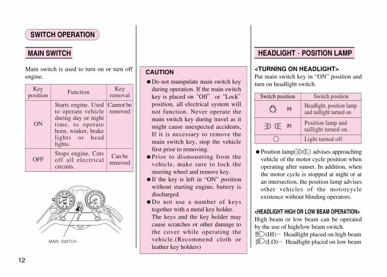
Main switch is used to turn on or turn offengine.
<TURNING ON HEADLIGHT>Put main switch key in “ON” position andturn on headlight switch.
●Position lamp advises approachingvehicle of the motor cycle position whenoperating after sunset. In addition, whenthe motor cycle is stopped at night or atan intersection, the position lamp advisesother vehicles of the motorcycleexistence without blinding operators.
<HEADLIGHT HIGH OR LOW BEAM OPERATION>High beam or low beam can be operatedby the use of high/low beam switch.
(HI)... Headlight placed on high beam(LO)... Headlight placed on low beam
SWITCH OPERATION
MAIN SWITCH HEADLIGHT·POSITION LAMP
CAUTION
●Do not manipulate main switch keyduring operation. If the main switchkey is placed on “Off” or “Lock”position, all electrical system willnot function. Never operate themain switch key during travel as itmight cause unexpected accidents,If it is necessary to remove themain switch key, stop the vehiclefirst prior to removing.
●Prior to dismounting from thevehicle, make sure to lock thesteering wheel and remove key.
●If the key is left in “ON” positionwithout starting engine, battery isdischarged.
●Do not use a number of keystogether with a metal key holder.The keys and the key holder maycause scratches or other damage tothe cover while operating thevehicle.(Recommend cloth orleather key holders)
Switch position
(H)
(P)
Switch position
Headlight, position lampand taillight turned on
Position lamp andtaillight turned on.
Light turned off
MAIN SWITCH
Starts engine. Usedto operate vehicleduring day or nighttime, to operatehorn, winker, brakelights or headlights.
Cannot beremoved
ON
OFF Can beremoved
Stops engine. Cutsoff all electricalcircuits.
Keyposition Function Key
removal
( )
**vl125(~47P) 02.11.5 4:33 PM 페이지12

This switch is the device for immediateengine stop by hand in any emergencies.In normal condition, make sure its position“ ”(RUN), and do not use on the positionof “ ”(OFF).
13
ENGINE STOP SWITCH
CAUTION
●Use this engine stop switch inemergencies.
●When this engine stop switchchanges as “ ”(RUN) “ ”(OFF) “ ”(RUN) during travel,engine cannot operate properly andalso it causes unsafety riding.Make sure the engine can bedamaged by this kind of misuse.
●When you make engine stop by thisswitch, the main switch must be in“ ”(OFF) position. If the key isleft in “ON” position withoutstarting engine, battery is dis-charged.
●If this switch is left in “ ”(OFF)position, engine cannot be started.
ENGINE STOP SWITCH
HEADLIGHT HIGH/LOW BEAM SWITCH
HEADLIGHT SWITCH
**vl125(~47P) 02.11.5 4:33 PM 페이지13

Starter motor runs while this button ispressed to start engine.
Use winker switch when you turn to left orright, or when you change course of travel.
<HOW TO USE>If this switch is turned on when the mainswitch is in “ON” status, turn signal isbrinking.To release, turn signal operation, press thewinker switch.
(R) .... Turn to right(L) .... Turn to left
14
STARTER BUTTON WINKER SWITCH
CAUTION● Using light-bulbs with wrong watts
may cause malfunction to thewinker switches. Always use light-bulbs with prescribed watts.
● The winker switch does not auto-
matically turn back to its original
position after completing the turn.
Please set the switch back to its
center position after turning.
Driving the vehicle with the light on
may hinder traffic. STARTERBUTTON
WINKER SWITCH
CAUTION
●Do not run starter motor continu-ously. Because the starter motorconsumes great amount of power,continuous running of starter motormight cause battery to exhausted.
**vl125(~47P) 02.11.5 4:33 PM 페이지14

If horn button is pressed when main switchis in “ON” position, horn is sounded
To prevent theft, lock steering wheel whenparking the vehicle.
<HOW TO LOCK>1. Turn the steering wheel to left
completely.2. Insert main switch key.3. Turn the key 180°to the right.
If the steering wheel cannot be locked,move the steering wheel slightly to rightand left while turning the key.
4. Remove the key.
<HOW TO RELEASE>1. Insert main switch key.2. Turn the key 180°to the left.3. Remove key.
15
Caution
●To make sure steering wheel islocked properly, lightly turnsteering wheel to left and right andright and verify lock.
●Park the vehicle in places free oftraffic.
●Prior to operation, turn the steeringwheel to left and right to verify ifturning angles of left and rights areequal.
HORN BUTTON
STEERING WHEELLOCK
EQUIPMENT USAGE
STEERING WHEEL LOCKHORN BUTTON
**vl125(~47P) 02.11.5 4:33 PM 페이지15

There is a tool box inside the right frontside cover. Safeguard tools inside the toolbox.
<HOW TO USE>Use main switch key to open or close thetool box cover.
<REFULELING>●Open key cover ; insert main switch key
; turn key to right and fuel tank cap isopened.
●Fill gasoline up the bottom of level platelocated at the lower side of tank mouth.
●Push the tank cap correctly with handsand remove the main switch key. (If thefuel tank cap is not locked, the mainswitch key will not be removed)
FUEL CAPACITY : 17.3ℓ
16
TOOL BOX FUEL
CAUTION
●Make sure to stop engine and stayaway from fire when fueling.
●If gasoline is filled aboved the levelplate bottom, gasoline mayoverflow.
TOOL BOX
KEY COVER
FUEL TANK CAP
MAIN SWITCH KEY
CAUTION
●Put tools inside the tool box,and lock it with O-ring as noisemight occur while the vehicle ismoving
**vl125(~47P) 02.11.5 4:33 PM 페이지16

<FUEL COOK>The fuel cock lever arrow indicates thestatus of fuel.●ON....Gasoline is injected to carburetor
when engine is started.●OFF....Lever is placed on this position
when vehicle is stored for a longperiod of time or when fuelsystem is inspected ormaintained.
●RES....Indicates reserve fuel. If fuelruns out while driving with thefuel cock lever placed in the“ON” position, put the lever in“RES” position to use reservegasoline.
●RES....Replenish gasoline as soon aspossible at this time. Afterrefueling, turn lever to “ON”position.
Reserve fuel capacity:Approximately 2.9 liter
●Make sure to check the oil, gasoline,etc., before starting the engine.
●Please ensure that the main stand andthe side stand is in a up-position whenstarting the engine.
●Make sure that the front wheel is lockedwhen starting the engine.
●Drive with care for both safety reasonsand longer vehicle life.
●For 1month(or 1,000km) after purc-hasing the vehicle, drive moderatelyavoiding fast starts and fast acceleration.
17
CAUTION
●If the lever is not turned to “ON”reserve fuel runs out during traveland vehicle cannot be operated.
CORRECT DRIVING OPERATION
ON OFF RES
**vl125(~47P) 02.11.5 4:33 PM 페이지17

<WHEN ENGINE IS COLD(WINTER)>1. Verify the steering weel lock is released.2. Make sure engine stop switch is in “ ”
(RUN) position3. Make sure fuel cock lever is in “ON”
position.4. Turn on main switch.5. Put gear in neutral.
(Verify this with neutral indicator lamp)6. Open choke lever all the way.7. open throttle grip approximately 1/8 and
press starter button.8. Once engine is started, pull and release
throttle grip repeatedly to run engineidle until engine is heated, and closechoke lever completely. If enginewarming up takes time, run engine idlewith the choke lever slightly closed.
9. Verify side stand is positively inoriginal position and start slowly.
<WHEN ENGINE IS HOT(SUMMER)>1. Verify the steering wheel lock is released.2. Make sure engine stop switch is in “ ”
(RUN) position.3. Make sure fuel cock lever is in “ON”
position.4. Turn on main switch.5. Put gear in neutral.(Verify this with
neutral indicator lamp)
6. Close throttle grip and press starterbutton. (If engine is not started with 1-2times of trial, verify fuel cock lever is in“ON” position)
7. If engine is not started with throttle gripclosed, open throttle grip approximately1/8 to 1/4 and press starter button.
8. Verify side stand is positively inoriginal position and start slowly.
18
STARTING THE ENGINE
CHOKE LEVER
1/41/8
**vl125(~47P) 02.11.5 4:33 PM 페이지18

If engine cannot be started or vehicle doesnot move, check the followings.●Is there fuel in fuel tank?●Are you operating in accordance with
the instructions given in user’s manual?●Is fuse not cut?●Is starter motor running?●If starter motor is not running due to
battery consumption, try starting motorby using kick start technique.
Gear is shifted in 5-shift return system asshown on the right side drawing.●Close throttle grip and hold clutch lever
perfectly, and shift gear.●Touch pedal lightly with foot and shift
gear perfectly until you hear “Click” atthe pedal. If you apply excessive forcewhen shifting gear, transmission may bedamaged.
<GEAR DOWN OPERATION>If you gear down when you need to drasti-cally accelerate speed such as when youare passing another vehicle, speed can beaccelerated. If you ride too fast, it ad-versely affects engine because engine rev-olution is excessive.
19
IF ENGINE CANNOT BE STARTED
GEAR SHIFTING
CAUTION
●Exhaust gas contains harmfulsubstance such as carbonmonoxide. Start engine in well-ventilated places.
●If engine is not started within 3seconds after starter button ispressed, wait for approximately 10seconds and retry. This is torecover battery voltage.
●Do not run engine idle unreaso-nably. This not only wastes fuel butalso adversely affects engine.
●If starter button is pressed withoutdisengaging clutch, motorcyclemay bring out to fall. Make suregear is in neutral position ordisengage clutch prior to startingengine.
GEAR CHANGE PEDAL
1
543
2
**vl125(~47P) 02.11.5 4:33 PM 페이지19

20
●Make sure side stand is in originalposition prior to starting vehicle.
●If side stand moves unsatisfactorily,check lubrication state on side standjoint.
●Shift gear adequately according tovehicle speed. The table on the rightside shows speed ranges.
●To save fuel and maintain optimumvehicle life, do not accelerate ordecelerate speed abruptly.
<BREAK-IN OPERATION>Maintain engine revolution at a level lessthan 6,000rpm for first 1,000km to breakin vehicle. If vehicle is broken in as above,the life span of equipment is prolonged.
●Apply brakes on front wheel and rearwheel simultaneously.
●Avoid unnecessary abrupt braking.
CAUTION
●Always start in the 1st gear, and startcarefully as slow as possible.
●If you hear abnormal noise duringtravel, contact authorized mainte-nance shop immediately forinspection and necessary action.
●Maintain legal speed limits.
CAUTION
●If you apply brakes only on frontwheel or rear wheel, vehicle mayslide off sideway and fall.
●If you apply brakes abruptly duringtravel in rain or on wet road, tiresslide off and may cause accidents.Reduce speed and apply brakecautiously.
●Avoid repeated brake operation asit may cause brake temperature torise, leading to braking effectdeterioration.
OPERATION HOW TO USE BRAKE
**vl125(~47P) 02.11.5 4:33 PM 페이지20

<ENGINE BRAKE>If you turn throttle grip in reverse, enginebrake functions and, if you need strongerbraking, shift gear down from 4th to 3rdand so forth. When you travel on a longdescent or on a sharp descent, useintermittent braking technique and enginebrake simultaneously.
●Put gear in neutral and put main switchto “OFF” position to stop engine.
●Put fuel cock to “OFF” position.●Put vehicle on main stand and park on
level ground in places free of traffic. Ifyou park vehicle on an uneven ground,vehicle may fall.
<PARKING WHEN SIDE STAND IS USED>Stop vehicle on level ground and park withthe steering wheel turned to left.If the vehicle is parked in the followingway, vehicle may fall to side.●If the vehicle is parked with the steering
wheel turned to right, or if parked on aslope, sandy places, uneven ground orsoft ground, vehicle may fall.
●If is necessary to park in an unstableground under unavoidable situation,take sufficient safety measures toprevent vehicle from falling or moving.
21
CAUTION
●Select a safe place free of trafficand park vehicle.
●Muffler is hot. Park vehicle inplaces where there is no danger ofpeople making contact withvehicle.
PARKING
CAUTION
●Do not shift to lower gear whiletraveling at an excessive speed as itmay suddenly increase the enginespeed, adversely affect the engineand transmission, and cause the rearpart of the vehicle to be shaken.
**vl125(~47P) 02.11.5 4:33 PM 페이지21

Self inspect the motorcycle and haveregular maintenance inspections forincreased safety and the prevention ofaccidents.Self inspections before operation should beperformed an a daily basis prior tooperating the vehicle. ●Inspections of areas of concern.●Fuel check●Brake inspection●Tire inspection●Battery acid level inspection●Throttle grip Inspection●Clutch inspection.●Drive chain inspection.●Engine oil inspection.●Lights and winker inspection.●Back mirror inspection.●License plate inspection.
Check areas which caused for concernwhen last operating the vehicle.
Check gasoline to see if there is asufficient amount of gasoline to reach yourdestination.Refer to page 16 for refueling.
22
CAUTION
Observe safety rules when conductinginspections.●Exhaust gas contains harmful
substance such as carbon monox-ide. Do not carry out inspections onvehicle in closed places, or inpoorly ventilated places, withengine running.
●Conduct inspections on flat, solidground with the stand erected.
●Be careful of burns when con-ducting inspections immediatelyafter engine is stopped because theengine and muffler are hot.
●Stop engine and remove the keyprior to the vehicle maintenanceservice.
●If you are unable to correct troubleeven after you make adjustment orcorrection, contact authorizedmaintenance shops, dealers ordesignated repair shops fornecessary inspection and repairs.
INSPECTION OF CONCERNED AREA
FUEL CHECK
SELF INSPECTIONS BEFORE OPERATION
**vl125(~47P) 02.11.5 4:33 PM 페이지22

The front brake is the hydraulic disk type,and the rear brake is the drum brake type. As the brake pad wear, the brake fluidlevel drops.There are no adjustments to perform, butfluid level and pad wear must be inspectedperiodically.The system must be inspected frequentlyto ensure there are no fluid leaks.
[FRONT WHEEL]
<BRAKE LEVER FREE PLAY>Lightly squeeze the brake levers untiltension is felt to check for an appropriateamount of free play. No free play in thebrake levers or overly loose brake leversare indication of a problem in the brakesystem.
BRAKE LEVER FREE PLAY :10~20mm
<BRAKE FLUID LEVEL>
Put main stand in upright position on a flatground and operate steel wheel, and checkfluid when the top of master cylinder capis level.Check fluid level to see if it is below lowerlevel.If fluid significantly low, it may indicatefluid leakage on brake system. If thishappens, check fluid leaks or brakesystem. If this happens, check fluid leaksor damage on system and inspect jointsand clamps for looseness.
In addition, check hose and pipe protectivepart to sec if they make contact with otherparts when you make left or right turn dueto vibration during travel.
23
CAUTION
●Brake is an important part whichprotects your life. Make sure toinspect brake prior to daily use.
WARNING
●Brake fluid may cause irritation.Avoid contact with skin or eyes. Incase of contact, flush thoroughlywith water and call a doctor if youreyes were exposed.
●KEEP OUT OF REACH OF CHILDREN.
BRAKES
ENGINECSTOP
LOWER LEVEL
**vl125(~47P) 02.11.5 4:33 PM 페이지23

24
<REPLENISHING BRAKE FLUID>●Move steering wheel and set the top of
reserve tank level.●Clean dust and other foreign matter
from around master cylinder and takecaution not to allow foreign matter tofall inside master cylinder
●Open cap screw and remove diaphragm.●Replenish recommended brake fluid to
upper level inside master cylinder.Tighten cap accurately, paying attentionto the direction of diaphragmassembling, and avoid ingress of foreignmatter.
RECOMMENDED BRAKE FLUID IS DOT 3
CAUTION
●Do not fill brake fluid above upperlevel as it may cause brake fluid toleak outside.
●Exercise full caution, whenreplenishing brake fluid, not toallow dust or water to mix insidemaster cylinder.
●If the amount of brake fluiddecreases considerably, it is anindication of brake system trouble.
●To prevent occurrence of chemicalchange, do not use brake fluid ofdifferent manufacturer.
●Do not let brake fluid contactvehicle parts because it causesdamage to painted parts.
SCREW
UPPER LEVEL
MASTER CYLINDERCAP
DIAPHRAGMPLATE
DIAPHRAGM
**vl125(~47P) 02.11.5 4:33 PM 페이지24

25
<BRAKE PAD INSPECTION>Operate brake and, if the brake pad wearlimit line reaches the brake disc side, itindicates the pad has reached wear limit.
[REAR WHEEL]
Push the brake pedal with hands forresistance and check if the pedalmovement appropriate.If brake pedal movement is inappropriate,adjust the pedal free play using the rearwheel brake adjuster nut.
●To adjust pedal free play, turn adjusternut. After adjustment, push the brakepedal with hands until you feelresistance and verify the pedal free playis within prescribed level.
BRAKE PEDAL FREE PLAY :20~30mm
WEAR LIMIT LINE
BRAKE PEDAL
ADJUSTER NUT
20~30mm
**vl125(~47P) 02.11.5 4:33 PM 페이지25

26
<BRAKE SHOE INSPECTION>Push brake pedal completely and, if thebrake arm arrow and the “△” on brakepanel match each other, it indicates brakeshoe has reached its life limit.
<TIRE PRESSURE CHECK>Check for an appropriate level of airpressure by examining how the tire sits onthe ground. If you notice any abnormalitiesin the shape of the tire with regard to thearea contacting the ground, use a tiregauge to check tire pressure and adjust thetire pressure to the appropriate level.
<TIRE PRESSURE>
<CRACKS/DAMAGE>Check tire tread and sides for cracks anddamage.
<ABNORMAL WEAR>Check tire tread for signs of abnormalwear.
TIRES
× ×
SIZE
TIREPRESSURE
(kg/㎠)
1 PERSONRIDING
FRONT 2.00
90/90-18
130/90-15
2.00
2.00
2.00
REAR
REAR
FRONT
FRONT
REAR
2 PERSONRIDING
“△”MARKARROW MARK
CRACKS
DAMAGE
ABNORMALWEAR
CAUTION●In case brake pad or shoe reaches the
wear limit line, replace it immed-iately.Worn brake pad can cause an accidentdue to lack of power
**vl125(~47P) 02.11.5 4:33 PM 페이지26

<FOREIGN MATTER>Check tire tread and sides for nails, rocks,etc. That might have become wedged inthe tire.
<TREAD DEPTH>●Check the wear indicator(wear limit
marking) to see if there is an insufficientamount of tread remaining.
●If the indicators are visible, replace tirewith a new one.
<BATTERY ACID LEVEL CHECK>●Remove the four flange bolts, and take
off the right lower cover.
●Place vehicle in upright position andcheck battery acid of each cell to see ifit is between upper and lower level. Ifthe battery acid is near lower level,replenish distilled water.
27
BATTERY
CAUTION●If air pressure is inadequate or if there
are cracks, damage or abnormal wearon tires, it may cause tremblingsteering wheel and flat tire.
●This vehicle is equipped with tubetires. If you have flat tires, pleasecontact authorised maintenanceshops for inspection.
NAILS
ROCKS
WEAR INDICATORLOCATION MARKING
WEAR INDICATOR(WEAR LIMIT MARKING)
RIGHT LOWER COVER
**vl125(~47P) 02.11.5 4:33 PM 페이지27

<BATTERY ACID REPLENISHING>If the battery acid is insufficient, replenishdistilled water in the following sequence.① Loosen the bolt and open the battery
band.② Remove the battery breather tube from
the battery.③ Remove the negative pole side cord
first and the positive pole side cordnext.
④ Remove the battery and open thebattery cap. Fill distilled water to nearupper level.
⑤ Tighten the battery cap accurately tothe vehicle and install battery. Makesure, at this time, that side cord isconnected first, followed by sidecord.
28
BOLT
CORD
BOLT
BATTERY CAP
BATTERY BREATHER TUBE
CAUTION●Except designated attachment by
DAELIM MOTOR CO., LTD., donot attach any extra lighting device,because it may cause an earlydischarging of battery.
●There 2 injection molded bolt-shapes on the right side lowercover. Take precautions not tocause damage when removing thecover.
WARNING●When handling the battery stay
away from flammable materials.●KEEP OUT OF REACH OF CHILDREN.
UPPERLEVEL
LOWERLEVEL
**vl125(~47P) 02.11.5 4:34 PM 페이지28

●Check for smooth rotation of the throttlegrip from the fully open to the fullyclosed position at both full steeringpositions.
●Measure the throttle grip free play at thethrottle grip flange.The standard free play should be approx: 2~6 mm
●To adjust the free play, turn the adjuster.
29
CAUTION●Turn the ignition switch OFF
before disconnecting the terminalfrom the battery.
●When battery holder is opened, donot allow the side cord tocontact metal part.
●After installing battery, verify thebreather tube has been accuratelyassembled to elbow. If the breathertube is removed, the battery acidcauses damage to adjacent parts. Ifthe tube is bent and clogged, thebattery internal pressure rises andbattery case may be damaged.Follow instructions on the labelattached to vehicle for correctchecking procedure.
●If excessive amount of distilledwater put in, it overflows andcauses corrosion of affected part.
●Battery acid contains thin sulfuricacid. Prevent its contact with eyesor skin as it causes damage ifcontacted. If battery acid gets onpart of your body, immediatelyflush the affected area with cleanfor longer than 5 minutes, andconsult medical doctor fornecessary treatment.
●Make sure cords are not twisted orinserted when assembling battery tobattery holder.
THROTTLE GRIP
ADJUSTER
**vl125(~47P) 02.11.5 4:34 PM 페이지29

<LEVER FREE PLAY INSPECTION>Pull clutch lever until you feel resistance,and using a graduated ruler, check the leverend free play to verify it is within prescribedlevel.
<CLUTCH OPERATION>●When engine is idling, pull clutch lever
all the way and see if there is abnormalnoise or if you feel unusual heaviness.
●Slowly release clutch lever and start.Check at this time to see if clutch isengaged smoothly without slipping.
<CLUTCH LEVER ADJUSTMENT>Adjust lever free play by using the clutchcable’s clutch lever side or clutch sideadjuster.●To make major adjustment, loosen the
clutch side lock nut and adjust byoperating the adjuster.
●For fine adjustment, loosen the clutchlever side lock nut and turn adjuster.
●After adjusting, tighten lock nut. Afteradjustment is completed, pull clutchlever with hands until you feelresistance and verify the lever free playis within prescribed level.
CLUTCH LEVER FREE PLAY:10~20mm
■MAJOR ADJUSTMENT
■FINE ADJUSTMENT
30
CLUTCH
CAUTION●Upon completion of adjustment,
start engine and verify gear changepedal is operating smoothly.
10~20mm
ADJUSTER
ADJUSTER
LOCK NUT
LOCK NUT
**vl125(~47P) 02.11.5 4:34 PM 페이지30

●The service life of drive chain isdependent upon proper lubrication andadjustment. Poor maintenance can causepremature wear or damage to the drivechain and sprocket.
●The drive chain should be checked andlubricated as part of the Pre-rideInspection.
●Under severe usage, or when themotorcycle is ridden in unusually dustyor muddy areas, more frequentmaintenance will be necessary.
<INSPECTION>1. Turn the engine off, put vehicle in
upright position on the main stand andshift the transmission into neutral.
2. Remove the chain tensioner.
3. Move the position of chain tensionerroller up and down with hands to checkif the chain free play is withinrecommended range.
OPTIMA FREE PLAY : 50~60 mm
4. Rotate the rear wheel slowly and inspectthe drive chain and sprockets for any ofthe follwing conditions :
■DRIVE CHAIN① Damged rollers② Loose Pins③ Dry or Rusted Link④ Kinked or Binding Link⑤ Excessive Wear⑥ Improper Adjustment⑦ Missing O-ring
■SPROCKETS⑧ Excessively Worn Teeth⑨ Broken or Damaged Teeth
●A drive chain with damaged rollers,loose pins or missing O-ring must bereplaced.
●A chain which appears dry or showssings of rust, requires supplementarylubrication.
31
DRIVE CHAIN
50~60mm
CHAIN TENSIONER ROLLER
**vl125(~47P) 02.11.5 4:34 PM 페이지31

<ADJUSTMENT>●Drive chain slack slould be checked and
adjusted, if necessary, every 1,000km.●When operated at sustained high speeds
or under conditions of frequent rapidacceleration, the chain may requir morefrequent adjustment.
1. Place the motorcycle on its side standwith the transmission in neutral and theignition switch off.
2. Remove the chain tensioner.3. Loose the axle nut.4. Loose the lock nuts on both sides of the
swingarm.5. Turn both adjusting nuts an equal
number of turns until the correct drivechain slack is obtained. Turn theadjusting nuts clockwise to tighten thechain or counter clockwise to providemore slack.Rotate the rear wheel and recheckslack at other section of the chain.
OPTIMA FREE PLAY : 50~60 mm
6. Tighten the axle nut to specified torque.
AXLE NUT TORQUE : 6.0~8.0 kgf··m
7. Tighten the adjusting nuts lightly, thentighten the lock nuts by holding theadjusting nuts with a spanner.
8. Install the chain tensioner.
32
WARNING●If a torque wrench is not used for
this installation, see your authorizeddealer as soon as possible to verifyproper assembly.
CAUTION●If a torque wrench is not used for
this installation, see your authorizeddealer as soon as possible to verifyproper assembly.
●Make sure the right and left chainadjuster graduations are set in thesame position.
●After adjusting chain, check therear brake pedal free play.
●New motorcycle adapts endless-type drive chain. (end-type foraffer-sales service purpose)After once disassembling chain,chain clip can be accidentallyremoved, so change new one afterdisassembling chain even once.
50~60mm
CHAIN TENSIONER
ADJUSTER NUT
**vl125(~47P) 02.11.5 4:34 PM 페이지32

33
●Put vehicle in upright position on flatground and check engine oil level anddegree of pollution.
●Run engine idle for approximately 2~3minutes on flat ground and stop engine.Approximately 2~3 minutes thereafter,put vehicle in upright position andcheck engine oil and verify the oil levelis between the upper and lower level ofoil level gauge.
●Insert oil level gauge, without locking,and check oil level after removing oilgauge.
●If the oil level is near lower level,replenish oil to upper level.
If engine oil is polluted, it seriously affectsthe engine life span. Maintain appropriatelevel of oil, use correct type of oil andobserve oil exchange period.●Stand vehicle on the main stand on level
ground and run engine idle (warm up)for approximately 2-3 minutes.
●Stop engine and place a container underthe engine.Remove oil level gauge and drain bolt.
●Clean oil filter screen.●Check the condition of oil filter screen
seal rubber and, O-ring.●Close oil filter screen, spring, and oil
drain bolt, and replenish oil up to theupper level of the oil level gauge.
OIL CAPACITY: 1.2ℓ
<RECOMMENDED OIL>If oil sold on markets or privately-manu-factured oil(low-grade) is used, engine lifeis adversely affected, and the privilege ofwarranty repairs cannot be guaranteed.
ENGINE OIL LEVEL CHECK CHANGING ENGINE OIL
GRADE(SF, SH) GRADE(SE, SH)
UPPERLEVEL
LOWERLEVEL
OIL LEVEL GAUGE OIL FILTER SCREEN OIL DRAIN BOLT
OIL FILTER SCREEN SPRING
WARNING●Be sure to keep oil away from
children and pets. Dispose of usedoil properly.
**vl125(~47P) 02.11.5 4:34 PM 페이지33

34
[HEAD LIGHT, TAIL LIGHT]Start the engine and make sure the lightsturn on. Also check to see if the lights aredamaged or if there is dirt on them.
[BRAKE LIGHT CHECK]Turn the main switch to ON.While separately operating the front andrear brakes, check to see if the brake lightturns on. Also check to see if there is anydamage to the lens or if there is dirt on thebrake light.
[WINKER CHECK]Turn the main switch to ON.Check to see if all the winker in the frontand rear of the vehicle(including left andright sides) are flashing properly, At thesame time, check to make sure that theautomatic sound signal of the winker isworking. Check also to see if any of thelens are damaged or dirty.
Sit squarely on the seat and check to see ifyou have a good view behind the vehicleby looking at the rear view mirrors. Alsocheck for dirt and damage on the rear viewmirrors.
Check to see if there is any dirt or damageto the license plate. Also check to see if the license plate isfirmly secured to the vehicle.
CAUTION
●If you change engine oil imme-diately after engine is stopped, becareful of burns because the engine,muffler and engine oil are still hot.
●Exercise caution not to allow dustor other foreign matter to flow inwhen refilling engine oil. If oiloverflows, wipe off oil clean.
●If oil level is lower or higher thanprescribed level, engine isadversely affected.
●Do not mix oil with those ofdifferent manufacturers or grade, ordo not use low-quality oil as it maycause deterioration of oil, leadingto accidents.
●Clean the oil filter screen with freshcleaning oil every 4,000km.
● Be careful not to lose the oil filterscreen spring when assembling theoil drain bolts.
LIGHTS AND WINKER BACK MIRROR
LICENSE PLATE
**vl125(~47P) 02.11.5 4:34 PM 페이지34

35
MAINTENANCE
●The Required Maintenance Schedule specifies how often you should have your motorcycle served, and what things need attention.●It is essential that your motorcycle be served as scheduled to retain its high level of safety, dependability, and emission control
performance.●These instructions are based on the assumption that the motorcycle will be used exclusively for its designed purpose. Sustained high
speed operation, or operation in unusually wet or dusty conditions, will require more frequent service than specified in theMAINTENANCE SCHEDULE. Consult your authorized Daelim dealer for recommendations applicable to your individual needs and use.
**vl125(~47P) 02.11.5 4:34 PM 페이지35

36
Perform the Self Inspections Before Operation at each scheduled maintenance period.I: INSPECT AND, CLEAN, ADJUST, LUBRICATE OR REPLACE IF NECESSARYR: REPLACE L: LUBRICATE C: CLEAN
FUEL LINE I I I I
FUEL FILTER R R R R
THROTTLE OPERATION I I I I
CARBURETOR CHOKE I I I
AIR CLEANER C C C NOTE (2)
SPARK PLUG I R I
VALVE CLEARANCE I I I I
CARBURETOR IDLE I I I I
ENGINE OIL R R R R
ENGINE OIL FILTER R R R R
DRIVE CHAIN Every 1,000 : I and L
BATTERY ACID I I I
ITEM
★
★
★
★
★
★
★
★★
FREQUENCY ODOMETER READING(NOTE 1)
REMARK
MAINTENANCE SCHEDULE
×1,000Km 1 4 8 12
MONTH 6 12 18
**vl125(~47P) 02.11.5 4:34 PM 페이지36

37
BRAKE FLUID I I I NOTE (3)
BRAKE SHOE / PAD WEAR I I I
BRAKE SYSTEM I I I I
BRAKE STOP SWITCH I I I
HEADLIGHT ADJUSTMENT I I I
SUSPENSION I I I
CLUTCH I I I I
SIDE STAND I I I
BOLTS, NUTS, FASTENERS I I
WHEELS / TIRES I I I
STEERING HANDLE BEARING I I
ITEM
★
★
★
★
★
★
★★
★★
FREQUENCY ODOMETER READING(NOTE 1)REMARK
NOTES : (1) At higher odometer readings, repeat at the frequency interval established here.(2) Service more frequently when riding in unusually wet or dusty areas.(3) Replace every 2 years, or at indicated odometer interval, whichever comes first. Replacement requires mechanical skill.
★ If you do not have the appropriate tools or information to conduct maintenance, or if you feel you are not capable to performmaintenance on this vehicle, contact authorized dealers or repair shops for maintenance and repairs.
★★To ensure safety, inspections and maintenance of these parts must be carried out by dealers, or repair centers.
×1,000Km 1 4 8 12
MONTH 6 12 18
**vl125(~47P) 02.11.5 4:34 PM 페이지37
38
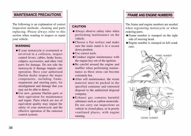
The following is an explanation of correctinspection methods, cleaning and partsreplacing. Please always refer to thissection when wanting to inspect or repairyour vehicle.
MAINTENANCE PRECAUTIONS
CAUTION
●Always observe safety rules whenperforming maintenance on thevehicle.
●Choose a flat surface and makesure the main stand is in a securedown position.
●Use correct tools.●Conduct engine maintenance with
the engine key out of the ignition.●Be careful around the engine and
muffler when performing mainte-nance as these areas can becomeextremely hot.
●After self maintenance, the wastematerial must be packed in thespecified container and entrusteddisposal to the authorized disposalcompany.
●Exhaust gas contains harmfulsubstance such as carbon monoxide.Do not carry out inspections onvehicle in closed place, or in poorlyventilated places, with enginerunning.
WARNING●If your motorcycle is overturned or
involved in a collision, inspectcontrol levers, cables, brake hoses,calipers, accessories, and other vitalparts for damage. Do not ride themotorcycle if damage impairs safeoperation. Have your authorizedDaelim dealer inspect the majorcomponents, including frame,suspension and steering parts, formisalignment and damage that youmay not be able to detect.
●Use new, genuine Daelim parts ortheir equivalent for maintenanceand repair. Parts which are not ofequivalent quality may impair thesafety of your motorcycle and theeffective operation of the emissioncontrol systems.
FRAME AND ENGINE NUMBERS
The frame and engine numbers are neededwhen registering motorcycle or whenordering parts.●Frame number is stamped on the right
side of steering head.●Engine number is stamped on left crank
case.
FRAME NUMBER
ENGINE NUMBER
**vl125(~47P) 02.11.5 4:34 PM 페이지38

<INSPECTION>●This vehicle is equipped with viscous
type air cleaner element containing oiland the element cannot be cleaned.
●Replace element after each operation of4,000km.
<DISASSEMBLING>●Loosen four screw and remove air
cleaner case cover.●Loosen four washer screw and air
cleaner element.
<ASSEMBLING>●Assemble in the opposite order of
disassembling.
① Put vehicle in upright position on a flatground.
② Start engine and let it run idle for a fewminutes.
③ Using the throttle stop screw, adjustidling to prescribed level.
IDLING REVOLUTION: 1,400±±100rpm
④ Tighten up pilot screw and loosebackward 1¾ to open.
⑤ Operate throttle lever lightly and verifythere is no change in the number of idlerunning. If there is a change, repeat theprocess described in paragraph ③ and ④
39
IDLE SPEED ADJUSTMENTAIR CLEANER ELEMENT
CAUTION
●If air cleaner element is inadequatelyassembled, dust and other foreignmatters are absorbed directly into theelement, inducing cylinder wear oroutput deterioration and adverselyaffecting engine durability. Asse-mble correctly.
●When cleaning vehicle, be carefulnot to allow water to get into aircleaner. If water gets inside aircleaner, it causes inefficient enginestarting.
SCREW
AIR CLEANER CASE COVER
THROTTLE STOP SCREW
AIR CLEANER ELEMENT
WASHER SCREW
**vl125(~47P) 02.11.5 4:34 PM 페이지39

[FRONT WHEEL REMOVAL]① Raise the front wheel off the ground by
placing a support block under theengine.
② Loose the oval screw and remove thespeedometer cable.
③ Remove the front caliper assemblyfrom the fork by removing the fixingbolts.
④ Loosen the axle nut.⑤ Withdraw the front wheel axle and
remove the front wheel.
⑥ Install in the reverse order of removal.
●Fit the caliper over the disc, taking carenot to damage the brake pads. Install thecaliper fixing bolts, and tighten to atorque of : 2.7kgf··m
●Tighten the front axle nut to the specifiedtorque.
FRONT AXLE NUT TORQUE :5.0~7.0kgf··m
⑦ After assembling, operate brake for anumber of times and see if wheel isturning smoothly without gettinginterruption.
40
WHEEL REMOVAL
CAUTION
●Do not operate brake lever after thefront wheel is removed. It willmake wheel assembling difficult.
CAUTION
●When installing the wheel, care-fully fit the left brake disk betweenthe brake pads to avoid damagingthe pads.
FRONT CALIPER
AXLE NUT
OVAL SCREW SPEEDOMETERCABLE
FRONT WHEEL AXLE
WARNING
●If a troque wrench was not used forinstallation, see your authorizeddealer as soon as possible to verifyproper assembly.
Improper aseembly may lead toloss of braking capacity.
**vl125(~47P) 02.11.5 4:34 PM 페이지40

[REAR WHEEL REMOVAL]① Set vehicle on main stand in upright
position on level ground.② Loosen the rear brake adjuster nut and
remove the brake rod.
③ Remove the chain tensioner.④ Loosen the chain adjuster nut.⑤ Loosen the rear weel axle nut and
remove the rear wheel axle and the rearwheel.
⑥ Install in the reverse order of removal.
REAR AXLE NUT TORQUE :6.0~8.0 kgf··m
●After installing the wheel, apply thebrake several times and then check if thewheel rotates freely. Recheck the wheelif the brake drags or if the wheel doesnot rotate freely.
41
WARNING
●If a troque wrench was not used forinstallation, see your authorizeddealer as soon as possible to verifyproper assembly.
Improper aseembly may lead toloss of braking capacity.
BRAKE ARM BRAKE ROD
CHAIN TENSIONERREAR WHEEL AXLE
CHAIN ADJUSTERNUT
**vl125(~47P) 02.11.5 4:34 PM 페이지41
·Be sure to turn the ignition switch OFFwhen replacing the bulb.
·Do not use bulbs other than thatspecified.
·After installing a new bulb, check thatthe light operates properly.
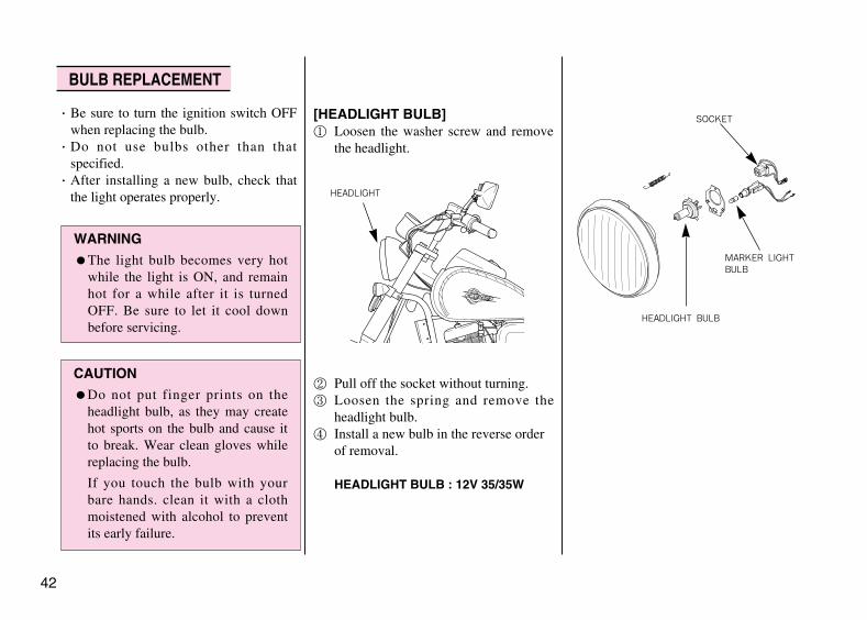
[HEADLIGHT BULB]① Loosen the washer screw and remove
the headlight.
② Pull off the socket without turning.③ Loosen the spring and remove the
headlight bulb.④ Install a new bulb in the reverse order
of removal.
HEADLIGHT BULB : 12V 35/35W
42
BULB REPLACEMENT
WARNING
●The light bulb becomes very hotwhile the light is ON, and remainhot for a while after it is turnedOFF. Be sure to let it cool downbefore servicing.
CAUTION
●Do not put finger prints on theheadlight bulb, as they may createhot sports on the bulb and cause itto break. Wear clean gloves whilereplacing the bulb.
If you touch the bulb with yourbare hands. clean it with a clothmoistened with alcohol to preventits early failure.
HEADLIGHT
HEADLIGHT BULB
MARKER LIGHTBULB
SOCKET
**vl125(~47P) 02.11.5 4:34 PM 페이지42
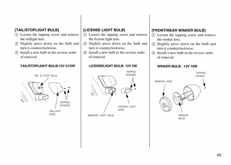
[TAIL/STOPLIGHT BULB]① Loosen the tapping screw and remove
the taillight lens.② Slightly press down on the bulb and
turn it counterclockwise.③ Install a new bulb in the reverse order
of removal.
TAIL/STOPLIGHT BULB:12V 21/5W
[LICENSE LIGHT BULB]① Loosen the tapping screw and remove
the license light lens.② Slightly press down on the bulb and
turn it counterclockwise.③ Install a new bulb in the reverse order
of removal.
LICENSELIGHT BULB: 12V 5W
[FRONT/REAR WINKER BULB]① Loosen the tapping screw and remove
the winker lens.② Slightly press down on the bulb and
turn it counterclockwise.③ Install a new bulb in the reverse order
of removal.
WINKER BULB : 12V 10W
43
TAIL & STOP BULB
TAILLIGHTLENS
TAPPINGSCREWS
MARKER LIGHT BULB
LICENSE LIGHTLENS
TAPPINGSCREWS
WINKER LENS
WINKERBULB
TAPPINGSCREW
**vl125(~47P) 02.11.5 4:34 PM 페이지43

44
If electrode is stained or plug gap is notright, satisfactory spark is not produced.Clean and make adjustment.●Remove spark plug cap.●Clean around the plug.●Using a plug wrench, remove plug.●Clean plug with plug cleaner.●Check electrode for wear and corrosion.
if the center of electrode became round,replace the electrode.
●Measure the spark plug gap using afeeler gauge.
PLUG GAP: 0.8-0.9mm
●Tighten with hands until the plugwasher touches cylinder head.
STANDARD PLUG: CR8EH-9
●If new plug is installed, turn 1/2 andtighten using a plug wrench.If plug is reused, turn 1/3~1/4 and tighten.
<DEALING WITH POOR STARTING>When the starter doesn’t work duringdriving in winter times or in a repeated shortdistance, use the suitable spark plug for thisdriving condition.Poor starting may happen when nonstopdriving in low speed, even though weproduce standard plug.In case starter isn’t working well in drivingrepeatedly in a short distance or in an areawith many traffic signals, use the CR7EH-9plug instead of standard plug CR8EH-9
SPARK PLUG
CAUTION
●If plug of different maker ordifferent heat value is used, itcauses unsatisfactory enginestarting, inadequate engine revol-ution and output deterioration.
●The spark plug must be securelytightened. An improperly tightenedplug can become very hot andpossibly damage the engine.
●To install a spark plug, turn it in asfar as possible with your fingers,then tighten it with a wrench.Do not overtighten or cross threadthe spark plug or the aluminumthreads of the cylinder head will bedamaged.Do not allow contaminantsto enter the engine through the sparkplug hole when the plug is removed.
PLUG GAP
**vl125(~47P) 02.11.5 4:34 PM 페이지44

Turn off main switch and check fuse forsign of cut.● Remove the four flange bolts, and take
off the right lower cover.●Fuse is installed inside fuse holder
located near battery.●To separate fuse, open fuse holder, hold
both ends of fuse cord and pull up, andpull out the fuse connector crosswise.
●If the newly replaced fuse is burnedagain soon, it is an indication of trouble.
45
FUSE REPLACEMENT
CAUTION●Turn the ignition switch OFF
before checking or replacing fuse toprevent accidental short-circuiting.
●When disassemble fuse, make surethat fuse holder isn’t separated.
●After assembling fuse in the part ofconnector, check if fuse moveseasily to a line. If fuse moveseasily, it may cause an accident atheating.
●When replacing any of the electricalparts (lights and gauges), be sure toreplace them with the recommendedparts. Using different parts can leadto the fuses burning out or damageto the battery.
●When washing the motorcycle takespecial card not to allow to besplashed in the area of the fuse.
WARNING●Never use a fuse with a different
rating from that specified. Seriousdamage to the electrical system or afire may result, causing a dangerousloss of lights or engine power.
FUSE HOLDER
<DISASSEMBLY> <ASSEMBLY>
FUSE CONNECTOR
CORD
**vl125(~47P) 02.11.5 4:34 PM 페이지45

●Erect main stand and place vehicle inupright position on level ground.
●Check side stand spring for signs ofdamage and lubrication state on joints.
A rubber part is assembled on the cable toprotect the inner cable.Make sure that this part is placed firmlyaround the correct part of the cable. Whenwashing the car, do not directly spraywater on to the rubber part is dirty, use adry cloth to clean this area.
●Make sure to stop the engine prior to carwashing.
●Be careful not to allow water to enterthe muffler during the washing.Water inside the muffler may cause animproper engine starting or rust occurr-ence.
●Do not let water get inside the brakingsystem during the washing, as waterinside the brake system may weaken thebraking power. Upon completion ofwashing, select a safe place where thereis no traffic obstruction, and start thevehicle. Lightly apply the brake whiledriving at a slow speed and check thebraking power. If the braking power hasbeen weakened, apply brake lightlywhile driving at a slow speed to dry upthe brake system.
●Take precautions when waxing thevehicle.Excessive polish of the painted sectionand/or the resin part with compoundwax might damage the painted sectioncausing discoloration of the affectedarea.
46
SIDE STAND CABLE RUBBER PART NOTABLES FOR CAR WASHING
INSPECTION PART INSPECTION PARTRUBBER
CONNECTOR
SIDE STANDSPRING
CAUTION●Infiltration of the foreign materials
or water caused by damage oflever(disengagement, tearing, etc.)may cause freezing in winterseason resulting in faulty operation,sudden accelation and brakingforce decrease. If any damage isfound, replace with the new onimmediately.
**vl125(~47P) 02.11.5 4:34 PM 페이지46

Extended storage, such as for winter,requires that you take certain steps toreduce the effects of deterioration fromnon-use of the motorcycle.In addition, necessary repairs should bemade BEFORE storing the motorcycle;otherwise, these repairs may be forgottenby the time the motorcycle is removedfrom storage.
<STORAGE>
●Empty the fuel tank into an approvedgasoline container using a commerciallyavailable hand siphon or an equivalentmethod.
●If storage will last more than one month,carburetor draining is very important, toassure proper performance after storage.
●Remove the battery. Store in an areaprotected from freezing temperaturesand direct sunlight. Slow charge the battery once a month.
●Wash and dry the motorcycle. Wax allpainted surfaces.
●Inflate the tires to their recommendedpressures. Place the motorcycle onblocks to raise both tires off the ground.
●Cover the motorcycle (don’t use plasticor other coated materials) and store inan unheated area, free of dampness witha minimum of daily temperaturevariation. Do not store the motorcycle indirect sunlight.
<REMOVAL FROM STORAGE>
●Uncover and clean the motorcycle.●Charge the battery as required. Install
the battery.●Perform all Self Inspections Before
Operation checks (page 22).Test ride the motorcycle at low speeds in a safe riding area away from traffic.
47
STORAGE GUIDE
CAUTION●Gasoline is extremely flammable
and is explosive under certain conditions. Perform this operation in a well-ventilated area with the engine stopped. Do not smoke or allow flames or sparks in the area where gasoline is drained or stored and where the fuel tank is refueled.
**vl125(~47P) 02.11.5 4:34 PM 페이지47

48
● Performing daily inspection
● Putting on the protective gears (Helmet, glove, goggles, etc.)
● Bringing the driver's licence
● Determinating the path to the desired destination
SAFE DRIVING
PREPARATION BEFORE DRIVING
도큐멘트1 02.11.5 4:51 PM 페이지1

The appropriate driving position is most important thing to driving safely.① Eyes : Look at the front direction widely.② Shoulders : Relieve the tension. ③ Arms : Relieve the tension and bend arms to inside and let
them act as the spring.④ Hands : Grip the handle the position away from the inside
end of the handle with distance of one finger tofacilitate the operation of the switch and lever.
⑤Wrist : Keep the state to act freely without applying excessive force to the shoulder and arms.
⑥ Knees : Press the fuel tank slightly.⑦ Feet : Place the feet to face the front parallel and make the
step bar be placed in the center of feet.
49
DRIVING POSITION
DRIVING METHOD
**VL125(48P~) 02.11.5 4:44 PM 페이지49

● Secure the safe distance.● Drive protectively.● Do not obstruct the traffic.● Do not drive on the pedestrian way or walkway. ● Drive on the left driveway when passing away.● Make sure that you can apply the brake anytime.● Always apply the brake when stopping temporarily.● Do not drive excessively long distance and take enough
break.
PRECAUTION WHEN DRIVING
50
● If any abnormality is found, stop driving and contact service center to inspect the vehicle.
● Restart the vehicle after 2~3 min when it is turned over.● Always turn on the headlight at night.
**VL125(48P~) 02.11.5 4:44 PM 페이지50

51
Prior to starting always look around to avoid accident.① Get on the vehicle after pulling back the stand. ② Start driving slowly after turning on the winker and
releasing the brake while ensuring the safety around the vehicle.
STARTING
CAUTION●Return the side stand to its original position, keep driving
without doing this may cause turnover accident.●Drive the vehicle only on the driveway. Driving on the walkway
can cause accident. Also, if the wheel is transformed whenadvancing directly to the walkway, the vehicle can be overturnedresulting in injury of the driver due to the driving unstability.
●Overspeed driving on the unpaved road can cause the vehicle tobe overturned resulting in injury of the driver due to the drivingunstability.
●Do not drive in the gravel road. If any gravel enters the wheel orengine case, the vehicle can be overturned resulting in injury ofthe driver.
●If possible, do not drive close to the sea or on the road wherecalcium chloride is treated. The muffler, external parts andwelded parts can be corroded rapidly, and also in case of damageof the frame, the vehicle can be overturned resulting in injury ofthe driver.
**VL125(48P~) 02.11.5 4:44 PM 페이지51

52
The basic principle of turn is balancing using the centrifugal force which makes vehicle go outside and the gravity which makes vehicle fall inside.
The centrifugal force increases in inverse portion to the radius of a curve and in portion to the square speed. Decelerate prior to entering the curved way to reduce the centrifugal force.
EFFECT OF SPEEDPRINCIPLE OF TURN
TURNING METHOD
**VL125(48P~) 02.11.5 4:44 PM 페이지52

53
The basic principle of turn is balancing using combined force of the centrifugal force and the gravity. All 3 positions require straightening the head and keeping the eyes horizontally.
< LEAN-WITH >This is a turning position with motorcycle and driver in a line.This position is the most natural and exact, so driver must learn it thoroughly.
< LEAN-IN >This is a turning position with driver leaned inside more than motorcycle. This position is adequate to drive on the rained or slippy road because it has best road holding.However, special attention is required because front visual field is poor when driver leans inside more than motorcycle.
3 POSITIONS OF TURNING
**VL125(48P~) 02.11.5 4:44 PM 페이지53

54
< LEAN-OUT >This is a turning position with motorcycle leaned inside more than driver, which is opposite to the lean-in position. With this position, quick turn is well performed and driver can obtain wide front visual field adequate to drive on the rained or slippy road because it has best road holding. However, special attention is required because there is danger of slipping on the bad holding road.
① Turn the throttle grip to its original position and decelerate using both front and rear brakes.
② Lean the vehicle toward inside of turn circle while driving slowly at constant speed.
③ Accelerate gradually.
TURNING METHOD
**VL125(48P~) 02.11.5 4:44 PM 페이지54

55
Do not drive inside of large truck's turn circle.
< DEAD ANGLE ZONE >Dead angle zone is the sight range which cannot be identified by driver and increases in proportion to the width of the motorcycle.
< DISTANCE BETWEEN THE FRONT AND REAR WHEEL TURN >It is distance between path of the front and rear wheel and increases in proportion to the length of the motorcycle.
PRECAUTION WHEN TURNING
**VL125(48P~) 02.11.5 4:44 PM 페이지55

56
● Vehicle is braked using friction between road surface and tires.
● Braking distance increases 1.5 times on wet road and 3 times on icy road because friction force of road surface is decreased.
Due to the inertia, motorcycle does not stop immediately after applying the brake.
BASIC PRINCIPLE OF BRAKE (FRICTION FORCE) RESTRAINT OF BRAKE EFFECT (INERTIA)
BRAKING METHOD
**VL125(48P~) 02.11.5 4:44 PM 페이지56

57
● Turn the throttle grip to its original position and decelerate using the engine brake.
● Erect the motorcycle straight.● Brake using both front and rear brakes.
·Vehicle speed : 50 km/h
Learn the proper braking method to prevent accident.
Impact increases in proportion to the speed and weight. The impact when collision to concrete wall at 50 km/h is same as one when falling from the height of 10m.
IMPACT WHEN COLLISION
COMPARISION OF BRAKING DISTANCE
BRAKING METHOD
**VL125(48P~) 02.11.5 4:44 PM 페이지57

58
GB/W
L/LGR
W /
RLG/
4
2
3
N1
5
GEAR POSITION S/W
12V 1.7Wx2EA
12V 1.7WILLUM, LAMP
BRG
BRG/YG
BRG
G
BRG/Y
BR
G
SB
G
G/YG
STOP & TAIL LIGHT
R. RR WINKER
L. RR WINKER
12V 21/5W
12V 10W
12V 5WLICENSE LIGHT
12V 10W
O
B B/L
LG G
R
B/LB
G
HORN
12V 9AH
BATTERY
R
Y/R
G/R
G
FUSE 15A
BB
G/YB
R
RR STOP SW.
SB
G
G/Y
O
BR
B/LB
FUEL GAGE WINKER RELAY
L2P
GR B
G
2P
GY/W
Y/W
Y/R
(ENGINE)
G
BR GYY
BR GY Y
REG-RECT
BODY EARTH
YY
L/Y
G/WYYB/R
B/R
G/W L/Y
L/YG W/L
B/W B/R
B/Y
CDI UNIT(AC)
IGN. COIL
ACG
O
LG
SB
GR
P
Y
G
L
W
R
B BR
EBA
T1IG
N
COMB SW.
BA
T2
RG/Y GB/W B
LIGHTKILL
ST.LI.KILL.SW.START
BR
L/W
B
B/G
B/G
Y/RBG
FR.STOP SW.SB
BR
Y/WB
4P M
INI
G
B
GY/W
BR
B/W
250 : BLACK
GR
3P
GRB
/W BB
B/W
G/Y
GBBR
9P
GY/R BBR
B/W
L/W
MINI
L/W
B/W Y/R
G/Y
SB OGR
LG BL G
BB/YSB
MIN
IB
SBB/Y
LG/RG
BR
6P
G
BRLG/R
L
L
GBR
O
4P M
INI
L
BRGO
L/W
GBR
B
G
Y/W
12V 10WR. FR WINKER
FU
EL
ME
TE
R
B
B/Y
G
SB
B
/R
GBR
LG
G
WINKER PILOT(R)
ILLUM, LAMP12V 3.4W or
NEUTRAL PILOT
12V 1.7W
12V 1.7W TA
CH
OM
ET
ER
G
GO
L
GBR
HIGH BEAM PILOT
WINKER PILOT(L)12V 1.7W
12V 1.7W
HEAD LIGHT
ILLUM, LAMP12V 3.4W S
PE
ED
OM
ET
ER
L
GSB
SB OGR
LG BL G9P MINI
B/YG
R L
BL
W2
Ho
BA
T
LoHi
W LG GR
SB O
G/W
G/W
BR
G
G
O
WIN. DIM. HORN SW.
HL
L/W
L/W
Hi Lo
L W
HL2
Hi
HORN
Ho
FREE
BAT
B Lo
(N)
COLOR L/W
GRCOLOR
PUSH
DIMMERWINKER
LRWTLTL
R
GR SB O
L
L/WBR COLOR
N
2BAT
OFF
START
ST1
FREE
ST2
P
H
COLOR B
B/G
PUSH
COLOR Y/R
LIGHTING
POSITION LIGHT
12V 35/35W
12V 4W
12V 10WL. FR WINKER
KILL
ST12E BAT
OFF
EXT
B/GBGCOLOR
RUN
B/W
IGNBAT1 2
ON
COMB. SW.
BAT
B/WR B
OFF
COLOR G
E
OG
G/WBR
G/WW W
2P
2P MINI
2P M
INI
4P M
INI
2P MINI
3P MINI
2P(ENGINE)
2P MINI
6P MINI
2P 4P
W/P W/P
WHITE
RED
YELLOW
GREEN
BLUE
BLACK
COLOR COMB : GROUND/MARKING
PINK
GRAY
ORANGE
SKY BLUE
LIGHT GREEN
BROWN
TLST
1 BAT2
BA
T2
EX
T
HLE ST
2
ST
1
WIRING DIAGRAM
**VL125(48P~) 02.11.5 4:44 PM 페이지58

MEMO :
**VL125(48P~) 02.11.5 4:44 PM 페이지59

OOWWNNEERR’’SS MMAANNUUAALL
2002. 05 PRINTED1999. 11 PUBLICATION NO COPY
*표2*표3 02.11.5 4:36 PM 페이지2