Technology for Controlling Emissions from Chromium Platinginfohouse.p2ric.org/ref/28/27146.pdf ·...
19
TECHNOLOGY FOR CONTROLLING EMISSIONS FROM CHROMIUM PLATING I. Composite Mesh Pad Technology A. Media Structure - Monofilament with specific configuration-pyramid or one shape B. Flat or round Filaments in random configuration. C. Monofilament may come in filament diameters or sizes as large as 40 mill and as small as 2 mill D. Each style has its own performance characteristics 1. Coarse styles A. High liquid handling capacity B. Pluggage resistance C. Efficient on 10 micron particles ti greater A. Reasonable liquid handling capacity B. Less pluggage resistance C. Efficient to 3-5 microns 2. Medium styles 3. Finer styles A. Low liquid handling capacity B. High pluggage potential C. Efficient to 1-3 microns E. Some simple pads comprised of multiple layers of one style of fiber diameter 1. These were in use at initial stages OE EPA Technology study A. Control largest visible droplets B. Keep chrome from spotting stack, roof, cars F. More complex pads comprised of several styles of fiber diameters composite mesh pads hence: G. Composite styles are extremely important for use on chrome 1. Requires liquid handling capacity in first and last stages 2. Requires high removal efficiency to meet emission limits
Transcript of Technology for Controlling Emissions from Chromium Platinginfohouse.p2ric.org/ref/28/27146.pdf ·...

27/46 Page 1
TECHNOLOGY FOR CONTROLLING EMISSIONS FROM CHROMIUM PLATING
I. Composite Mesh Pad Technology
A. Media Structure - Monofilament with specific configuration-pyramid or one shape
B. Flat or round Filaments in random configuration.
C. Monofilament may come in filament diameters or sizes as large as 40 mill and as small as 2 mill
D. Each style has its own performance characteristics
1. Coarse styles A. High liquid handling capacity B. Pluggage resistance C. Efficient on 10 micron particles t i greater
A. Reasonable liquid handling capacity B. Less pluggage resistance C. Efficient to 3-5 microns
2. Medium styles
3. Finer styles A. Low liquid handling capacity B. High pluggage potential C. Efficient to 1-3 microns
E. Some simple pads comprised of multiple layers of one style of fiber diameter
1. These were in use at initial stages OE EPA Technology study A. Control largest visible droplets B. Keep chrome from spotting stack, roof,
cars
F. More complex pads comprised of several styles of fiber diameters composite mesh pads hence:
G. Composite styles are extremely important for use on chrome 1. Requires liquid handling capacity in first
and last stages
2. Requires high removal efficiency to meet emission limits

Page 2
H. Best approach is to design for "Removal of Chromium droplets in stages by particle size"
1.
2.
3.
Design utilizes the largest monofilament at the scrubber inlet and gradually incorporate smaller monofilaments toward the outlet
Largest monofilaments remove majority of particles while protecting the smaller monofilaments from pluggage
Most designs in corporate 3-4 pads in series designed for following removal- Stage #1 - 10 microns & greater Stage #2 - 3-5 microns Stage #3 - 1 /micron Stage #4 - Reintrainment chamber
I. Principles of Operation
1.
2 .
3 .
Inertial impaction - larger droplets A.
B.
Particles travel with sufficient velocity to impact and adhere to the surface of a media Velocity must be fast enough to prevent droplet from following gas stream around fiber
Interception - smaller droplets A. Droplets carried around initial fibers but into
the path of downstream fibers
Agglomeration A. When smaller proplets travel along monofilaments
surface llAgglomerate" into larger particles 40-50 microns
1. Growing of chromium droplets 2.
B. Also known as coalescing
Takes place in pads containing finer monofilament styles with low liquid handling capacity Particles can not drain as quickly as they are reintrained
3.
C. "Re-entrained" particles are then collected on a down stream media (Re-entrainment Chamber) containing larger monofilament with high liquid handling capacity 1. drained of liquid
Large monofilaments allow for quick

J. How typical 3 or 4 stage CMP-Chrome Eliminator works
1.
2.
3.
4 .
5 .
6.
7.
Chromium evacuated from tanks by local exhaust system
Mist travels through duct system at velocities of 3000-3200 feet per minute (FPM)
Mist stream enters first stage of eliminator at 500 FPM A. Velocity reduction accomplished
by providing vessel with larger crossectional area
Largest chromium droplets inertially impact with stage one (which contains largest monofilament) and most all particle sizes above 8-10 microns are collected
Remaining mist steam enters stage #2 (which contains large to medium and medium to finer monofilament) and most particle sizes 3-5 microns are co 11 ec ted
Remaining mist enters stage #3 A. This stage is protected by stages
l b r 2 B. Where coalescing or agglomeration
takes place. Contains finest monofilament
C. Crossection is reduced and velocity is increased 20-30% in stage #3
D. Particles are grown (previously described) most are them re-entrained as larger particles
Re-entrained particles then enter stage #4 where these particles are collected and adequately drained
page4
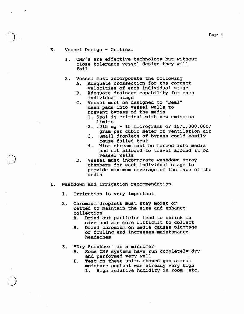
K. Vessel Design - Critical
-3
1. CMP's are effective technology but without close tolerance vessel design- they will fail
2. Vessel must incorporate the following A. Adequate crossection for the correct
velocities of each individual stage B. Adequate drainage capability for each
individual stage C. Vessel must be designed to "Seal"
mesh pads into vessel walls to prevent bypass of the media 1. Seal is critical with new emission
limits 2. .015 mg - 15 micrograms or 15/1,000,000/
gram per cubic meter of ventilation air 3 . Small droplets of bypass could easily
cause failed test 4 . Mist stream must be forced into media
and not allowed to travel around it on vessel walls
Vessel must incorporate washdown spray chambers for each individual stage to provide maximum coverage of the face of the media
D.
L. Washdown and irrigation recommendation
1. Irrigation is very important
2. Chromium droplets must stay moist or wetted to maintain the size and enhance collection A. Dried out particles tend to shrink in
B. size and are more difficult to collect Dried chromium on media causes pluggage or fowling and increases maintenance headaches
3 . "Dry Scrubber" is a misnomer A.
B. Test on these units showed gas stream
Some CMP systems have run completely dry and performed very well
moisture content was already very high 1. High relative humidity in room, etc.

Page 5
4 . Most conditions require continuous irrigation on one or more of the stages to provide for moisture and sustain particle size of droplet
5. Remaining stages typically flushed periodically with wash water being returned to tank to make up evaporative losses
6. Wash down requirement can vary due to conditions of inlet loading, hours of operation, atmospheric conditions, etc.
7 . Typical manufacturers recommended washdown requirement: A. Stage #1 continuous irrigation but at low volume
approximately 1/4-1/2 GPM per square foot of pad crossection 1. If continuous washdown is not feasible due to
low evaporative loss in tank then calculation should be done to maximize periodic washdown duration and frequency
Stage #2 2-4 times a shift for approximately 20-25 seconds Stage #3 4-8 times a shift for approximately 20-25 seconds Stage #4 reintrainment chamber does not typically require washdown
B.
C.
D.
8. Automatic washdown panels should be used due to the high frequency washdown requirements of todays chrome eliminator A. Panels contain cycle timers for frequency and
B. Activates a solenoid valve at spray chamber to timer relays or PLC’s for duration
initiate washdown
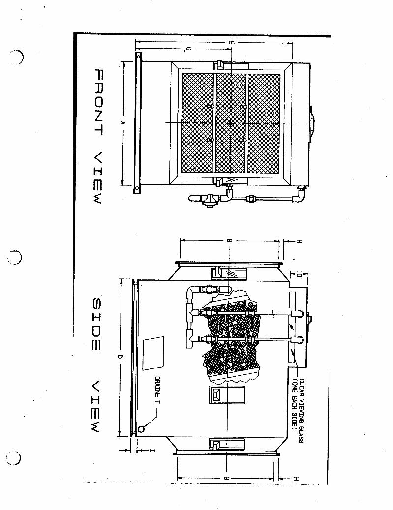
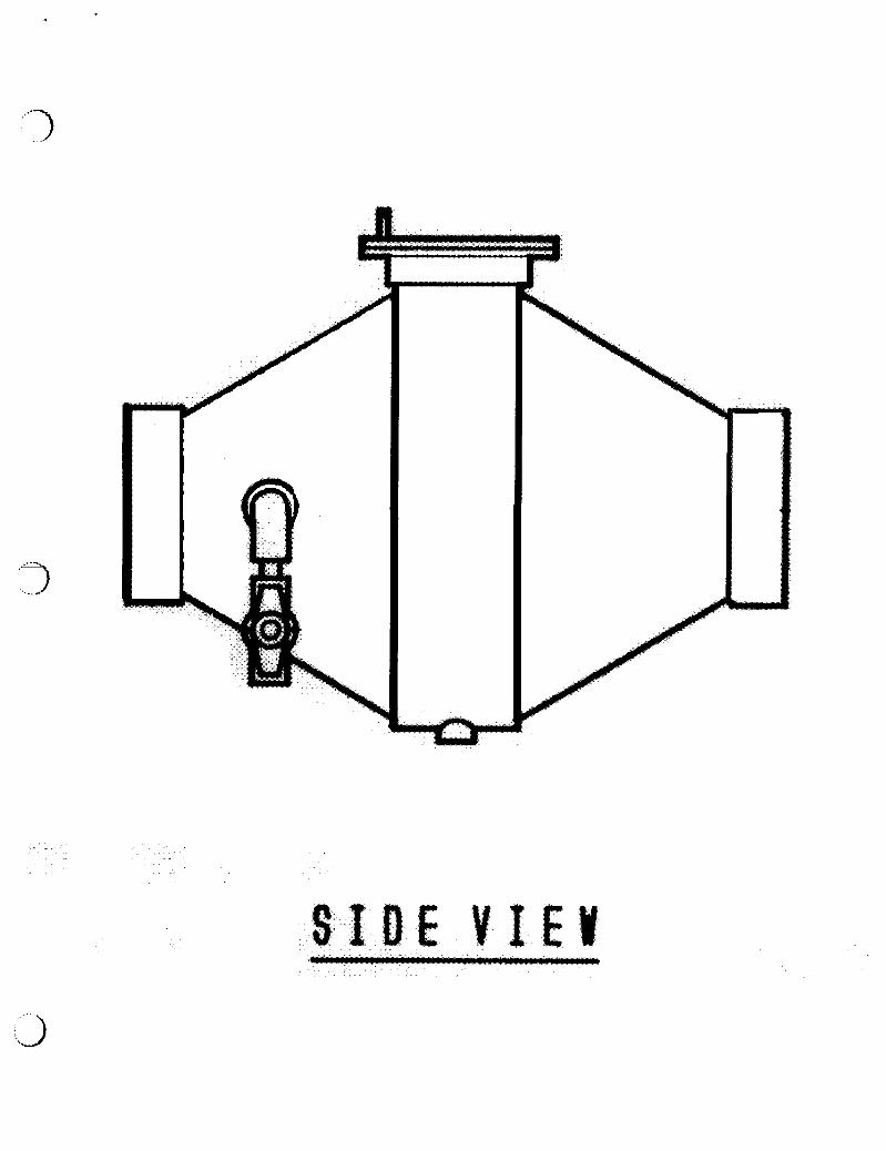
M. Precontrol devices
1. Precontrol device can be valuable to use for two reasons A. Reducing the inlet loading into the main control
B. Collecting majority of largest chromium droplets at the source keeps ductwork cleaner, minimizing wear and possibility of leaks.
device--Keeping it cleaner and reducing maintenance requirements
2. Typically consist of a single mesh pad in smaller vessel designed to maintain velocity of 600 FPM

Page 6
Typically mounted just above or close to exhaust hood "Inline" with ductwork
3.
4 . In line Mist Eliminator should incorporate largest monofilament with high liquid handling capacity, must be resistant to pluggage
Pre control mesh pads can also be designed into the body of the exhaust hood
5.
6 . When precontrol is utilized inline a three stage chrone eliminator in leiu of four stages can be recommended
11. Wet Packed Bed Scrubber
A. USEPA based the emission limit required of existing small hand chrome platers of .03mg/DSCM on the wet pack scrubber
1. Have strong data to show that a well designed, well maintained pack bed scrubber can achieve the .03
2. EPA considered the financial burden on small plater by allowing this technology to be used
B. Wet Scrubbers are designed typically for absorption of compounds that evolve in a gas (HCL-NH3, N02, H2S, etc.)
Designed for packing media to distribute a scrubbing solution to contact the gas and promote "mass transfer" of gas into liquid stream
C.
D.
E.
Chromium evolves in mist form not as a gas
Therefore chrome wet scrubbers work mechanically as wet collectors not gas absorbers
F. Wet Scrubbers consist of: 1. Vessel capable of a velocity of 500 FPM or below 2. Depth or bed of random (dump) packing (typically
1-3 feet) 3. Spray chambers and recirculation system to
continuously saturate pack 4 . Mist eliminator to remove re-entrained scrubbing
solution

Page 7
G. How a wet scrubber operates
1. First the gas stream is slowed to at or below 500 FPM
2. The mist stream first comes in contact with an initial spray chamber-saturating the particles causing some to fall out of the air stream by gravity
3 . The mist stream then contacts the packed media impacting on the media and the fluid layer being distributed by packing
4 . Droplets eventually washed to the bottom of the scrubber
5. Last stage is mist eliminator to remove re-entrained scrub solution A. Chevron Blades - 4 directional air changes B. Mesh pad
H. Best wet scrubber design for chrome
1. Choose quality packing A. Maximize surface area and drip points
2, Three foot packed bed
3 . Irrigate at 4 GPM/sq.ft. of scrubber crossection
4 . Specify over head spray chamber for good liquid distribution and addition of fresh water
5. Keep chromium concentration of recirculated solution below 4-6 oz/gal
6. Data shows this design has been tested to remove greater than 99% of all particle size 2 microns and above
-3

Page 8
I. Types of scrubber packing commonly used
1. Palil rings
2. Cascade mini rings
3. Saddles
4 . Spheres
5. Tri-pack
6 . Tellerettes
7 . Polyhedron-Lanpac * 8 . Multiple drip points (pincushion) Nupac
** Data shows good removal efficiency on chrome ** J. Adding composite mesh pads to your existing wet scrubber
1. Wet scrubber in good shape can be used as first stage in a higher efficiency control device
If it is required for .015 to be achieved, mesh pad section in proper vessel can be mated to outlet side of wet scrubber A. Minimum of two pads should be utilized as add on
1. Composite pad consisting of larger filaments in up stream to protect subsequent layers and fine monofilament in the down stream for coalescing
capacity as final stage
2.
2. Re-entrainment pad with all larger monofilament with good liquid handling
K. Monitoring Equipment
1. Mact requires for CMP systems to have device pressure drop to be monitored and recorded once a day ( ( + - ) 1 inch W.C)
2. Manufacturers recommendation is for each stage to have capability for pressure drop monitoring

age 9
3. Easiest done with magnahelic gauge A. Reads pressure drop in inches of water B. Can be equipped with 4-20 milliamp
transmitter and set points C. To send signal to PLC for recording or
alarm
4. Can also be done with a photohelic gauge A. Same as magnahelic but equipped with set
points and a llOv output to energize alarm or system shutdown.
5. MACT requires pack bed scrubbers to have device pressure drop and inlet gas velocity monitored once a day A. Gas velocity easily monitored using air
velocity magnahelic gauge reading in inches of water and feet per minute, connected to a pitot tube traversing the inlet duct diameter 1. Specific instructions for properly mounting
and calibrating pitot and gauge are specified in MACT
L. Two technical papers have been presented along with this outline, in your manual
1. Scrubber technologies and their maintenance
2. Applicability of the promulgated MACT standard for chromium emissions to current available "Add on" control technology
n 73 0 Z i
< m c H
(0
o m
< m x
H
H
I
u B P -I
I

n a 0 Z -I
<
z H m
co U H
m
<
x H m
1 F -- - - H
0 I 1 . L

B 6
..-3
T O P V I E W
I D
I
A H
F

E CAP TYPE ACCESS DOORS I 1 5' '
HEADER PIPE
PRESSURE GAUGES (OPT.)
REMOVABLE HEADERS
FLANGED INLET - CLEAR ACCESS PORTS - PLUMBING UNION
-
-B I P.P. SPRAY NOZZLES
MESH PAD SECTIONS
BALL VALVE (TYP.)
PLUMBING UNION
N = DRAIN DIAMETER f I I
I F - L = COATED STEEL BASE SIZE
F R O N T V I E W S I D E V I E W

'7 .
'.3
1 I I L L
x I I 1

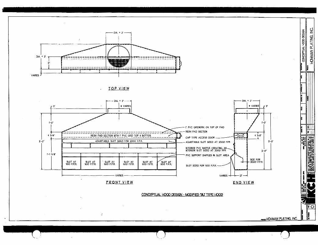
r D'Ai+ ' 1
n R I n VARIES
T O P V I E W
I VARIES VARIES IT 4 F R O N T V I E W E N D V
COKE"AL CKX)D DESIGN - MODIFIED W TYPE HOOD