Technological Processes
223
Technological Processes
Transcript of Technological Processes

Technological Processes

S.C. Roşia Montană Gold Corporation S.A. – EIA Report Chapter 2 Technological Processes
ii
Contents 1 Introduction 9 2 General Project Description ............................................................................10
2.1 Extraction Technology .............................................................................10 2.1.1 Open Pit Design 10
2.2 Processing Technology............................................................................10 2.3 Aqueous System Treatment ....................................................................11
2.3.1 Treatment of water containing cyanide 11 2.3.2 Acid Rock Drainage Treatment 13
2.4 Tailings Management Facility– TMF ........................................................15 2.4.1 TMF Functions. Class and Category of Importance. Technological Parameters 15
2.4.1.1 TMF Functions. 15 2.4.1.2 Class and Category of Importance 15 2.4.1.3 Technological Parameters 15
2.4.2 TMF Components and Staged Construction Characteristics 16 2.4.2.1 Tailings Management Facility 16
3 Construction Phase.........................................................................................21 3.1 Processes, Operations, Activities ............................................................21
3.1.1 Site Preparation 21 3.1.2 Preparatory Works 22 3.1.3 Development of quarries for construction materials (La Piriul Porcului Sandstone Quarry; Sulei Andesite Quarry) 25 3.1.4 Waste Rock and Low-grade Ore Stockpiles 25 3.1.5 Tailings Impoundment 26
3.1.5.1 TMF Site Characteristics 26 3.1.5.2 TMF Design 32 3.1.5.3 Dam Stability 38
3.1.6 Power Lines and Electrical Substations 42 3.1.7 Road Construction 42 3.1.8 Construction of the process plant and ancillary facilities 43 3.1.9 Fresh Water Supply System 45 3.1.10 Temporary Hazardous Waste Storage Facility 45
3.2 Equipment, Material, Utilities, Access Roads, Workforce Requirement...45 3.2.1 Materials and Equipment 45 3.2.2 Facilities – Temporary Constructions: 48 3.2.3 Utility services - temporary facilities 48
3.2.3.1 Temporary Water Supply and Distribution: 48 3.2.3.2 Temporary Power: 48
3.2.4 Access Roads 49 3.2.5 Workforce 49
3.3 Pollution Sources .....................................................................................49 3.3.1 Emissions 49
3.3.1.1 Atmospheric emissions 49 3.3.1.2 Sources of Emissions to Water 50 3.3.1.3 Pollutant Emissions on SOIL/SUBSOIL 51
3.3.2 Noise and Vibration 51 3.4 Waste.......................................................................................................52
4 Operation Phase .............................................................................................54 4.1 Operations ...............................................................................................54
4.1.1 Ore Extraction Operations 54 4.1.1.1 Preparatory Works 54 4.1.1.2 Mining Works 55 4.1.1.3 Waste Rock Stockpiling 58 4.1.1.4 Mine Dewatering 59
4.1.2 Ore Processing 59 4.1.2.1 Ore Processing Technology 59 4.1.2.2 Main Technological Processes 62

S.C. Roşia Montană Gold Corporation S.A. – EIA Report Chapter 2 Technological Processes
iii
4.1.2.3 End Products and By-products 75 4.1.2.4 Process Tailings 75
4.1.3 Industrial Wastewater Treatment 76 4.1.3.1 Cyanide Aqueous System Treatment 76 4.1.3.2 Treatment of Aqueous System with Cyanide Content - Roşia Montană Project 83 4.1.3.3 ARD Treatment 99
Cyanide Balance ....................................................................................................115 4.1.4 Tailings Management Facility - TMF 119
4.1.4.1 TMF Operation 119 4.1.4.2 TMF Preparation for Operation 119 4.1.4.3 TMF Start-up Procedures 119 4.1.4.4 Normal Operating Procedures 120 4.1.4.5 Slurry Pumping and Piping System Tailings Deposition and Dam Raise 121 4.1.4.6 Process Water, Precipitation and Upstream Flood Management 121 4.1.4.7 Management of TMF Seepage 124 4.1.4.8 Geochemistry of Tailings deposited in the TMF 124
4.1.5 Auxiliary processes 134 4.1.5.1 Lime management (storage, preparation, use) 134 4.1.5.2 Reagent Management (storage, preparation, use) 135 4.1.5.3 Thermal plant 137 4.1.5.4 Emergency electrical power generator 137 4.1.5.5 Fuel Storage Facility 137 4.1.5.6 Compressed Air 137 4.1.5.7 Oxygen plant 138 4.1.5.8 Control Systems 138
4.2 Equipment and material needs, facilities, services, access roads, workforce 139 4.2.1 Equipment needs 139
4.2.1.1 Equipment needs – mining operations 139 4.2.2 Material requirements 144
4.2.2.1 Ore Mining 144 4.2.3 Facilities (buildings, laboratories, storage areas) 145
4.2.3.1 Gate house 145 4.2.3.2 Administration building 145 4.2.3.3 Crib room and laboratory 145 4.2.3.4 Plant storage facility and workshop 145 4.2.3.5 Crib room and mine workshop 145 4.2.3.6 Vehicle washing station 145 4.2.3.7 Explosives magazine and ANFO silos 145 4.2.3.8 Communication and Information Technology 145 4.2.3.9 Site Security 146 4.2.3.10 Fire Protection 146
4.2.4 Services 147 4.2.4.1 Water supply 147 4.2.4.2 Fresh Water Supply 147 4.2.4.3 Drinking Water 147 4.2.4.4 Industrial water 148 4.2.4.5 Domestic wastewater 149 4.2.4.6 Wastewater management 149
4.2.5 Electricity 156 4.2.6 Access Roads 156 4.2.7 Workforce 157
4.3 Pollution Sources ...................................................................................157 4.3.1 Emissions 157
4.3.1.1 Atmospheric emissions 157 4.3.1.2 Water Pollutant Emissions 164 4.3.1.3 Pollutant Emissions on SOIL/SUBSOIL 165 4.3.1.4 Noise and Vibration 166
4.3.2 Waste 167 4.3.3 Rehabilitation measures in the event of temporary suspension of operations 167
4.3.3.1 Tailings Management Facility (TMF) 168 4.3.3.2 Waste Rock Stockpiles 168 4.3.3.3 Open Pits 169 4.3.3.4 Cetate Water Catchment Dam and Pond 169 4.3.3.5 Wastewater Treatment 169

S.C. Roşia Montană Gold Corporation S.A. – EIA Report Chapter 2 Technological Processes
iv
4.3.3.6 Sludge Management 169 4.3.3.7 Miscellaneous Facilities 169 4.3.3.8 Site Water Management 169
5 Closure Phase...............................................................................................170 5.1 Activities.................................................................................................170
5.1.1 General approach 170 5.1.2 Closure of mining operations 171 5.1.3 Closure of processing activity 173
5.1.3.1 General Considerations 173 5.1.3.2 Decommissioning of crushed ore stockpiling area 175 5.1.3.3 Decommissioning of milling, classification and gravitational concentration plant 176 5.1.3.4 Decommissioning of Carbon-in Leach, carbon stripping, electrowinning and smelting plants 177 5.1.3.5 Decommissioning of reagent management area, excluding cyanide detoxification plant 178 5.1.3.6 Decommissioning of ancillary installations, buildings and industrial structures 179 5.1.3.7 Decommissioning of cyanide detoxification (DETOX) plant 179 5.1.3.8 Temporary hazardous waste storage facility decommissioning 180
5.1.4 TMF Closure 180 5.1.4.1 Assessment of water management associated with the TMF during closure and post-closure 181 5.1.4.2 TMF seepage management and semi-passive treatment during closure and post-closure [22] 182 5.1.4.3 Covering of the tailings deposited in TMF and revegetation 184 5.1.4.4 Water Management during Closure 187
5.1.5 Electricity 194 5.1.6 Access Roads 194
5.2 Equipment and material needs, facilities, services, access roads, workforce 194 5.3 Pollution Sources ...................................................................................195
5.3.1 Emissions 195 5.3.1.1 Atmospheric emissions 195 5.3.1.2 Water Pollutant Emissions 195 5.3.1.3 Pollutant Emissions on SOIL/SUBSOIL 196 5.3.1.4 Noise and Vibration 197
5.3.2 Waste 197 5.4 Revegetation..........................................................................................198
6 Use of the best available techniques (BAT) ..................................................200 6.1 Limit values for the relevant parameters achieved by application of the proposed techniques and the best available techniques......................................................200 6.2 Comparison between the best available techniques and management strategies for the major impact categories ............................................................................207 6.3 Use of the Best Available Techniques (BAT) and Best Environmental Practices (BEP) for TMF Management ................................................................................215
6.3.1 General principles of BAT regarding processing tailings are: 215 6.3.2 Management Throughout the Project Life 215
6.3.2.1 During the Design Phase 215 6.3.2.2 Environmental Baseline Studies 215 6.3.2.3 Studies for tailings characterisation 216 6.3.2.4 Studies and plans for the Tailings Management Facility (TMF) 216 6.3.2.5 TMF and associated structure design 217 6.3.2.6 TMF management and monitoring 217
6.3.3 Acid Rock Drainage Water Management - ARD 218 6.3.4 Cyanide Management 218
S.C. Roşia Montană Gold Corporation S.A. – EIA Report Chapter 2 Technological Processes
v
List of Tables Table 2-1 Mine Schedule by Pit Areas Table 2-2 Mineable Reserves Table 2-3 Hydrogeologic Properties Table 2-4 Seismic Hazard Analysis Table 2-5 Summary of the engineering properties of the foundation and fill materials Table 2-6 Stability Analyses Table 2-7 Stability Analyses Table 2-8 Stability Analyses Table 2-9 Earthworks Table 2-10 Estimated material quantities Table 2-11 Material for construction of the TMF dam Table 2-12 Sequencing of waste excavations Table 2-13 Configuration and charging parameters Table 2-14 Volumes of excavated ore Table 2-15 Waste Rock Stockpiling Table 2-16 Waste rock distribution by open pit and stockpiling location Table 2-17 Volumes of ore that will be enter the process plant Table 2-18 Balance for the crushing and crushed ore stockpile Table 2-19 Balance for ore grinding and classification operations Table 2-20 Material balance for the leaching process Table 2-21 Material balance for the elution - stripping process Table 2-22 Material balance for the carbon reactivation process Table 2-23 Physical-chemical composition of tailings slurry (50% MTS) Table 2-24 INCO (SO2/aer) Process – Summary of the results of the testing conducted by Cyplus/Inco for final determination of the operational parameters Table 2-25 Treatment of tailings slurry from the Roşia Montană ore processing activities applying the INCO (SO2/aer) process Table 2-26 Alternative processes tested for treatment of tailings slurry from the Roşia Montană ore processing activities Table 2-27 Physical-chemical characteristics of treated slurry (representative samples – laboratory / pilot scale Table 2-28 Influence of dilution and natural attenuation processes on the cyanide concentration (CN-
t si CN-u.e.) in the TMF during operations (pH = 8-8.5)
Table 2-29 Slurry / decant water treatment possibilities during operations - temporary closure - closure - post-closure Table 2-29 Concentrations of sulphates achieved through certain ARD treatment plants Table 2-30. Calcium and sulphate concentrations in water discharged from various neutralisation plants – lime precipitation Table 2-31 ARD Physical-Chemical Characterisation (2003) Table 2-32 Physical-chemical characterisation per treatment stages (influent – ARD 714 adit) Table 2-33 Variation of Mn concentration vs. pH (NTPA 001 – Mn = 1 mg/l) Table 2-34 Variation of Al concentration vs. pH (NTPA 001 – Al = 5 mg/l) Table 2-35 Physical-chemical characterisation of effluents per treatment phases (influent – synthetic ARD) Table 2-36 Characterisation of process chemical sludge Table 2-37 TMF Parameters Table 2-38 TMF Foundation and Fill Materials Seepage Properties Table 2-39 Mobile mining equipment requirement Table 2-40 Raw and ancillary materials, type of energy used Table 2-41 Fresh water supply to the process plant

S.C. Roşia Montană Gold Corporation S.A. – EIA Report Chapter 2 Technological Processes
vi
Table 2-42 Site Pipelines Table 2-43 Supernatant Water Composition Table 2-44 Limit values for the relevant parameters achieved by application of the proposed techniques and the best available techniques Table 2-45 Comparison between the best available techniques and management strategies for the major impact categories

S.C. Roşia Montană Gold Corporation S.A. – EIA Report Chapter 2 Technological Processes
vii
List of Figures Figure 2.1. Mining works Figure 2.3. Tailings Slurry Detoxification Flow Sheet Figure 2.4. Treatment plant influent/effluent ARD water diagram Figure 2-5. ARD treatment Figure 2.6. Cyanide balance Figure 2.7. TMF Storage capacity during operations Figure 2.8. Phasing of vehicle procurement Figure 2.9. Roşia Valley water management during operations Figure 2.10. Corna Valley water management during operations Figure 2.10. Roşia Valley water management during closure Figure 2.11. Corna Valley water management during operations Figure 2.12. Water management at closure Figure 2.13. Water management at post-closure

S.C. Roşia Montană Gold Corporation S.A. – EIA Report Chapter 2 Technological Processes
viii
Exhibits Exhibit 2.1 Project Location in Romania Exhibit 2.2 Current Conditions Exhibit 2.3 Site Layout Plant - end of year 0 Exhibit 2.4 Site Layout Plant - end of year 07 Exhibit 2.5 Site Layout Plant - end of year 14 Exhibit 2.6 Site Layout Plant - end of year 16 Exhibit 2.7 Site Layout Plant at mine closure - end of year 19 Exhibit 2.8 Facilities Related to the Construction Phase Exhibit 2.9 Mine Roads and Access Roads Exhibit 2.10 Processing Plant Site Exhibit 2.11 Simplified Overall Process Flow Diagram Exhibit 2.12 Ore Receiving, Crushing and Stockpile Process Flow Diagram Exhibit 2.13 Grinding Circuit Exhibit 2.14 A and 2.14 B Leaching/Adsorption Process Flow Diagram Exhibit 2.15 Elution/Regeneration Process Flow Diagram Exhibit 2.16 Electro-winning and Smelting Process Flow Diagram Exhibit 2.17 Thickening & Cyanide Detoxification Process Flow Diagram Exhibit 2.18 Tailings Management Facility Final Dam Exhibit 2.19 Tailings Management Facility Schematic Exhibit 2.20 Cross-Sections throught Main Dam and Secondary Containment Dam Exhibit 2.21 Major Transport Routes Exhibit 2.22 Simplified Water Balance - Schematic Flow Balance Exhibit 2.23 Detailed Water Balance - Schematic Flow Balance Exhibit 2.24 Ausenco Carbon Regeneration Process Flow Diagram Exhibit 2.25 Ausenco Lime Storage and Preparation Flow Diagram Exhibit 2.26 Ausenco Cyanide and Sodium Hydroxide Mixing Flowsheet Exhibit 2.27 Ausenco Copper Sulphate and Sodium Metabisulphite Mixing Flowsheet Exhibit 2.28 Ausenco Flocculant Mixing and Hydrochloric Acid and Carbon Dioxide Storage Flowsheet Exhibit 2.29 Ausenco Air Compressor Schematic Exhibit 2.30 Ausenco Fresh Water Distribution Schematic Exhibit 2.31 Ausenco Gold Smelting and Mercury Retort Flowsheet Exhibit 2.32 Ausenco ARD Treatment Flowsheet Exhibit 2.33 Ausenco Truck Wash and Fuel Storage Facility Schematic Exhibit 2.34 Ausenco Processing Plant Design Criteria Exhibit 2.35 Ausenco Processing Plant Design Criteria Exhibit 2.36 Ausenco Reagent Design Criteria Exhibit 2.37 Ausenco Services Design Criteria Exhibit 2.38 Geotechnical Exploration Map Exhibit 2.39 TMF Geotechnical Cross-Sections Exhibit 2.40 TMF Geotechnical Cross-Sections Exhibit 2.41 TMF Geotechnical Cross-Sections Exhibit 2.42 Surface Water Diversion Channels Corna Valley Exhibit 2.43 Starter TMF and SCD Excavation Plan Exhibit 2.44 Starter TMF and SCD Dam Plan Exhibit 2.45 Starter TMF and SCD Starter Dam Cross Sections and Details Exhibit 2.46 Final Tailings Management Facility & Secondary Containment Dam Plan (at closure) Exhibit 2.47 Final Tailings Management Facility & Secondary Containment Dam Plan Cross Section Exhibit 2.48 TMF Filling Plan Sequence Exhibit 2.49 Starter TMF Basin Preparation Plan Exhibit 2.50 Schematic Geological Cross Section
S.C. Roşia Montană Gold Corporation S.A. – EIA Report Chapter 2 Technological Processes
Section 1: Introduction
Page 9 of 223
1 Introduction This chapter addresses the technological processes associated with all phases of the
mine life (construction, operation, and decommissioning/closure) in accordance with Ministerial Order (M.O.) No. 863 of 26.09.2002 on Approval of the methodological guidelines applicable to the stages of the environmental assessment procedure, Annex 2, Part II, Content of the Report to the Environmental Impact Assessment. It should be noted that M.O. 863, Annex 2, Part II, requires estimation of the limit values for the total water and power consumption, total pollutants in air and water, and limit values related to waste generation, as well as their comparison with limit values to be achieved by applying the Best Available Techniques recognised by (EU) or other recognised best environmental practices. This information is provided at the end of Section 2, in Table 2.1 (Annex 1), in the specific format required pursuant to M.O. No. 863/2002.
S.C. Roşia Montană Gold Corporation S.A. – EIA Report Chapter 2 Technological Processes
Section 2: General Project Description
Page 10 of 223
2 General Project Description RMGC is proposing to develop and extend the current gold and silver mine in the
vicinity of the comuna of Rosia Montanã in Alba County, Romania. As shown in Exhibit 2.1, Rosia Montanã is located approximately 80 km northwest of
the regional capital of Alba Iulia, and 85 km north-northeast of the city of Deva in west-central Romania. The Project area lies in a region known as the Golden Quadrilateral in the Apuseni and Metaliferi Mountains of Transylvania. This Golden Quadrilateral has been the most important gold-producing region of Europe for over 2000 years.
The area covered by the the Rosia Montana mining concession (hereinafter referred to as the “Rosia Montana Project or the "Project”) and the region as a whole are severely impacted in terms of environmental conditions by the previous mining operations. As opposed to this situation, construction, operation, management and environmental rehabilitation activities will be conducted according to international environmental and social performance standards never applied to any other project developed in the region. It is estimated that the Roşia Montană Project will establish a benchmark for mining projects in Romania or locations in the Danube basin.
The existing mine (hereinafter referred to as the "Rosiamin" operation) is a small-scale and degraded open pit mine owned and operated by the state-owned company C.N.C.A.F. “MinVest” S.A. (“MinVest”).
The Roşia Montană Project is owned and managed by RMGC, a joint venture comprising Regia Autonoma a Cuprului Deva, (later Minvest) (19.31%), Gabriel Resources Limited (Canada) (80%), and three minority shareholders: Cartel Bau, Foricon S.A. and Comat S.A., each with 0.23%.
An Exploitation Concession License was granted to Minvest (the titleholder) and RMGC (as an affiliated company) in December 1998 and the license came into force in June 1999. In October 2000, the license was transferred from Minvest to RMGC, with Minvest as an affiliated titleholder. As such, Minvest is entitled to continue its current small-scale RoşiaMin mining operations at Roşia Montană, while RMGC conducts exploration and early project development activities, until such time as RMGC makes a production decision in relation to the Roşia Montană Project, Minvest remains responsible for all current mining operations at Roşiamin, including all current environmental issues, as well as issues related to the anticipated closure of the Rosiamin operation.
Based on the completion of economic/mining option modelling (see Section 5), the Roşia Montană Project is designed to extend over a period of 14 years, followed by an additional 3 years for the processing of the low-grade ore. This period will be followed by completion of decommissioning, environmental restoration and rehabilitation activities and long-term environmental monitoring. Current models propose an average throughput of 13 Mtp to be processed annually over a period of almost 16 years.
2.1 Extraction Technology
2.1.1 Open Pit Design The Roşia Montană gold and silver deposit existing will be mined by conventional
open pit mining (descending flat benches and waste rock haulage to offsite dumps). The mine development program in the Roşia Montană area involves opening of four
open pits located on both sides of the Roşia Valley at depths ranging between 220 m/170 m and 260 m/420 m. The open pit development will follow the mineralization.
2.2 Processing Technology
The ore being mined during the RMGC mining operation will be transported to a processing plant equipped with a SAG mill and grinding circuit consisting of two ball mills. Following grinding, the ore will undergo conventional cyanide leaching processes for
S.C. Roşia Montană Gold Corporation S.A. – EIA Report Chapter 2 Technological Processes
Section 2: General Project Description
Page 11 of 223
recovery of metal content from the ore. The low concentrations of cyanide compounds resulting in this process will be subject to cyanide detoxification (weak acid dissociable/WAD cyanide concentrations will be reduced to levels that comply with applicable EU standards) within the process plant prior to the tailings discharge into the Tailings Management Facility (TMF).
The tailings slurry resulting from ore processing contains cyanide and heavy metal and will be subject to thickening in order to decant and recycle some of the water containing cyanide; the thickened tailings will be further treated through a SO2/air cyanide detoxification circuit using lime for destruction of cyanide and precipitation of heavy metals. The cyanide detoxification process will reduce the WAD cyanide concentrations in the treated tailings slurry to levels below 10mg/l, in accordance with the provisions of the new EU-Directive for the Management of Waste from the Extractive Industries.
2.3 Aqueous System Treatment
The mining industry, in case of mines using cyanide for metal recovery, several types of aqueous systems may occur requiring treatment prior to discharge to the environment.
• tailings slurry containing cyanide which is normally routed to the tailings pond either treated or untreated.
• decant water containing cyanide which is recycled from the tailings management facility back to the process throughout the operations; under specific conditions or in certain phases of the mining operation water may be discharged to the environment and may require treatment.
• acidic and metal bearing mining impacted water resulting at the contact between stormwater and ARD generating rocks exposed to atmospheric oxygen;
• seepage water from various storage, decant etc. facilities having the same characteristics as the water from the respective facilities;
• domestic wastewater. This is complemented by clean stormwater collected from the site to prevent the
contact with contaminated waters and reuse the clean water in order to achieve an efficient water management system.
This Section and following subsections describing the various processes throughout all phases of the Project, as well as Section 4 containing subsections on wastewater management issues (source, treatment, discharge) and Section 5 addressing alternatives further detail aspects regarding treatment processes for various water systems associated with the Project.
Therefore, this Section will only provide a summary, an introduction to the wastewater treatment specific to the gold mining process conducted at Roşia Montană.
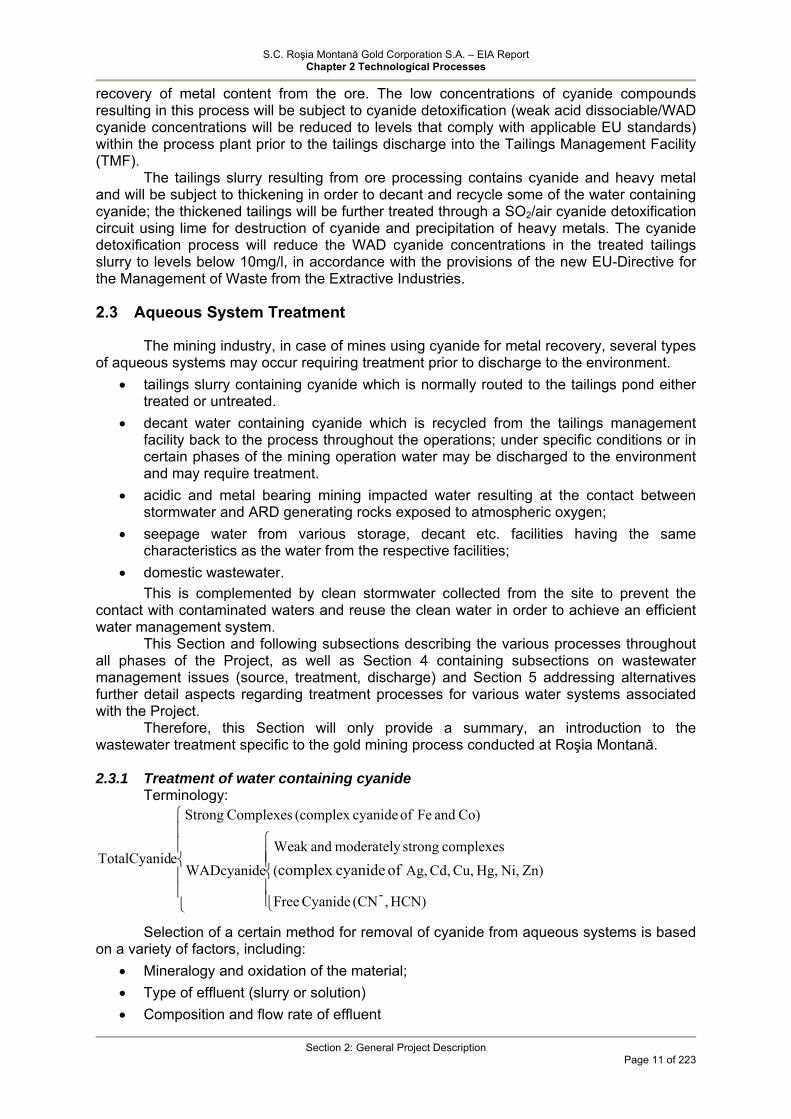
2.3.1 Treatment of water containing cyanide
Terminology:
⎪⎪
⎩
⎪⎪
⎨
⎧
⎪⎪⎩
⎪⎪⎨
⎧
HCN),-(CN Cyanide Free
Zn)Ni, Hg, Cu, Cd, Ag, ( complexes strong moderately andWeak
W
Co) and Fe of cyanide(complex Complexes Strong
Tof cyanidecomplex ADcyanide
eotalCyanid
Selection of a certain method for removal of cyanide from aqueous systems is based on a variety of factors, including:
• Mineralogy and oxidation of the material; • Type of effluent (slurry or solution) • Composition and flow rate of effluent

S.C. Roşia Montană Gold Corporation S.A. – EIA Report Chapter 2 Technological Processes
Section 2: General Project Description
Page 12 of 223
• Discharge quality requirements (discharge limits) • Availability of reagents • Capital and operating costs • Legislation that may restrict use of certain reagents • Tolerance to deviations under operating condition
Cyanide removal processes from industrial effluents may be grouped into the following categories:
Destructive procedures based on oxidation (including photo oxidation) / bio oxidation: • alkaline chlorination; • SO2/air process (INCO, Noranda); • Hydrogen peroxide process (Dupont-Kastone); • Caro’s acid oxidation; • Combin Ox technology; • Ozone oxidation; • Electrochemical oxidation; • Biological methods;
Recovery processes: • HCN stripping at low pH (AVR process); • Recycling of cyanide effluents; • ion exchange processes (Vitrokele, Augment); • adsorption on activated carbon.
Other methods: • Precipitation processes (Prussian Blue); • Natural degradation (likely processes: volatilization, photochemical degradation,
oxidation/biological oxidation, hydrolysis, precipitation, adsorption); • DTOX process.
The current detoxification alternatives for cyanide containing effluent/slurry and wastewater generated by the mining industry identified by BREF BAT Reference Document on Best Available Techniques for Management of Tailings and Waste-Rock in Mining Activities (reference [3], Section 5.4.4), are as follows:
• alkaline chlorination; • SO2/air process (INCO, Noranda); • Hydrogen peroxide oxidation process (Dupont-Kastone); • HCN stripping at low pH (AVR process); • adsorption on activated carbon. • biological treatment; • natural degradation.
Out of the above mentioned detoxification processes, the followings are applied at industrial scale in the mining industry: • for concentrated aqueous systems such as tailings sllury: alkaline chlorination, SO2/air
process (most widespread, increasingly replacing chlorination), hydrogen peroxide process;
• for low concentration wastewater (such as supernatant water in the pond, seepage): hydrogen peroxide process, biological treatment, natural degradation, adsorption on carbon (developing method).
o Given the following considerations:

S.C. Roşia Montană Gold Corporation S.A. – EIA Report Chapter 2 Technological Processes
Section 2: General Project Description
Page 13 of 223
• Particularity of the Roşia Montană ore and tailings slurry resulting from ore processing (ratio between WAD cyanide and total cyanide favorable to the first category, and ratio between free cyanide and WAD cyanide, favorable to free cyanide);
• European and international experience at industrial scale; • BAT recommendations regarding likely applicable methods; • large production capacity at Roşia Montană determining the flow rate and volume of
wastewater requiring treatment, The following treatment systems for aqueous solutions containing cyanide have been
developed within the Project: • for tailings slurry: thickening for recycle of cyanide-containing water in the mineral
extraction process, treatment of thickened tailings will be further treated through a SO2/air (INCO) cyanide detoxification circuit and discharge of treated tailings to the TMF with WAD cyanide concentrations below 10mg/l, in accordance with the Directive of the European Parliament and of the Council on the management of waste from the extractive industries. in the TMF – continuous cyanide concentration reduction by multiple natural degradation/mitigation with efficiencies of some 50% depending on the season, in accordance with the process modelling results and references to other mines. Under normal conditions, the decant water is recycled from the tailings management facility back to the process throughout the operations and will be used to supply much of the water required for the mineral processing. Throughout the operations the TMF seepage which may contain cyanide or cyanide degradation compounds will be collected in the Secondary Containment System and pumped back to the TMF basin.
• 3 processes have been proposed in the amended Project for low cyanide concentration water (peroxide oxidation, adsorption on activated carbon or a sorbent resulting from dry bone distillation and reverse osmosis) which will be tested at laboratory scale during the construction period. The optimal secondary cyanide treatment process identified following testing will be
developed at large operational scale and used during operations and closure for the treatment of:
• TMF decant water during abnormal operational conditions (extreme meteorological events) or temporary closure associated with extreme meteorological events in case discharge is required (the designed capacity for 2 PMP events is exceeded) and the requirements of the NTPA 001/2005 are not met by natural dilution (CNt
- ≤ 0,1 mg/l); • at the end of operations when the TMF decant water and collected seepage are used
for environmental rehabilitation by flooding of the Cetate pit if the NTPA 001 standard is not met. A series of passive/semi-passive treatment lagoons downstream of the SCS sump
will be tested during operations (last three years) for the treatment in the closure and post-closure phase of seepage and ARD water generated in the area; if the treated water meets the quality requirements it will be discharged into the Corna valley, otherwise the water will be further treated, subject to the type of contamination and Project phase, through the secondary cyanide treatment plant or ARD treatment plant.
2.3.2 Acid Rock Drainage Treatment
ARD water is typically characterized by high sulphate concentrations, high levels of dissolved metals (Al, Fe, Mn and other heavy metals) and acid pH.
This type of water generated within active/closed/abandoned mining tenements represents a long-term “stress” factor, particularly for the environmental components soil and water (surface water and groundwater). Therefore, appropriate measures for ARD treatment must be applied, with the mention that the remediation strategies should consider the changes in mine water flows and quality occurring over time.

S.C. Roşia Montană Gold Corporation S.A. – EIA Report Chapter 2 Technological Processes
Section 2: General Project Description
Page 14 of 223
The treatment methods for acidity reduction and heavy metal and sulphate removal can be grouped into the following categories:
• Active: addition of alkaline chemical reagents/waste in conjunction with ventilation, as appropriate (oxidation of iron, manganese ions occurring in reduced form)
• Passive: rehabilitated swamps (lagoons), drains, active barriers etc.; • Combine: active + passive treatment
The Project ARD generation sources are generally associated with historical mining operations and also with works developed within the new Project.
Potential ARD runoff will be collected in two catchment ponds, the Cetate waste and mine drainage pond and the Cîrnic waste rock and mine drainage pond (located in the Rosia and Corna valley, respectively) and pumped to the ARD treatment plant.
The plant designed to treat a flow rate of 400-600 m3/h (maximum level reached in year 9 of operation as a result of the development of mine workings) applies a method recommended by BAT, one of the most widely used internationally in the mining industry which consists of the following:
• air oxidation – pH adjustment/ metal precipitation using milk of lime – settling (pH =9.7-11);
• pH optimisation using CO2 (pH = 8.5) - precipitation of aluminium and separation of suspended solids. The process allows pH adjustment and metal precipitation to levels that meet the
requirements of the NTPA 001/2005. The followings are excepted from the respective requirements: calcium, sulphates and in relation thereof, fixed residue which have concentrations determined by the solubility of the calcium sulphate (approximately 2 g/l).
The Project amendments include: • optimisation of precipitation for improved removal of calcium; • sulphate precipitation in the form of ettringite in the presence of calcium aluminate.
Once calcium and sulphates are removed from the system, the content of dissolved salts in water will also decrease.
Thus, the optimised process provided in the Project ensures compliance with NTPA 001 quality requirements for all indicators. It should be noted that the eco-toxicologic studies conducted on fish, Daphnii, algae show that the calcium sulphate is toxic for the environment at concentrations over 2800-3000mg/l.
The water treated in the first stage enters the process water circuit for recycling, while water resulting in the final treatment stage will be used to maintain the biological baseflows in the Corna and Rosia streams; part of the resulting sludge is recycled to the treatment plant to improve precipitation, and the remaining sludge is transported for deposition in the Tailings Management Facility.
The ARD treatment plant will remain operational in the post-closure period; it will be later decided based on the treatment requirements at the time whether the plant will remain at its existing location or it will be relocated.
During closure, the ARD flow rate will decrease significantly as some of the water sources cease to exist while for other sources measures for ARD prevention have been provided.
During closure treatment of the water accumulated in the Cetate pit lake will be carried out in situ using lime from the ARD treatment plant.
During closure and post-closure a passive/semi-passive treatment lagoon system will be developed in Rosia Valley (similar to the Corna Valley) for ARD treatment; during closure the system will work in parallel with the active process and will be the only treatment option in the post-closure phase.
Domestic wastewater is treated using typical systems appropriate for the various phases of the Project as shown in the sections below.

S.C. Roşia Montană Gold Corporation S.A. – EIA Report Chapter 2 Technological Processes
Section 2: General Project Description
Page 15 of 223
The treatment methods for the aqueous systems associated with the Roşia Montană Project are detailed below for certain phases of the Project as per the scope of the following sections and requirements of the Framework Contents of the Impact Assessment Study.
In all cases the employed methods ensure discharge to the environment in compliance with the quality standards provided by the Romanian legislation.
2.4 Tailings Management Facility– TMF
2.4.1 TMF Functions. Class and Category of Importance. Technological Parameters 2.4.1.1 TMF Functions.
The purpose of the Roşia Montană ore processing operations is the recovery of useful minerals, i.e. gold and silver.
The gold and silver grade of the ore is less than 10 g/t, which means that basically the entire volume of extracted and processed ore can be considered as a form of waste material which needs to be managed in a manner that does not pose any risk to the environment or human health.
In accordance with worldwide practices employed for similar conditions and capacities a waste management method consisting in the deposition of process tailings to a Tailings Management Facility was adopted; this method is also recommended by BAT (Best Available Techniques for Management of Tailings and Waste-Rock in Mining Activities – Draft March 2004) [2] and the Best Environmental Practices also mentioned in the European Directive on the Management of Waste from the Extractive Industries [3].
The TMF main functions are as follows: • storage of tailings generated by ore processing operations in a manner that
minimises potential hazards to human health and the environment; • to ensure 100% recycling of the process water to the plant and "zero discharge" to
environmental media under normal operating and climatic conditions; • continuation of the treatment process (biodegradation by exposure to ultraviolet
radiations) of the cyanide and WAD cyanide compounds down to the permissible limits for waste water discharge into the receiving body of water;
• deposition of the sludge from the ARD treatment plant during operations; • containment of ARD run-off from the Corna Valley Watershed.
2.4.1.2 Class and Category of Importance In accordance with the provisions of STAS 4273-83 "Hydrotechnical Constructions – Classification within Importance Classes", the Tailings Dam is classified by the designer as Class I of Importance. The Category of Importance established by the designer as per NTLH-021 "Technical Norms for Hydrotechnical Works" is Category B. 2.4.1.3 Technological Parameters The main technological parameters for the Valea Corna TMF are as follows:
• the flow rate of slurry discharging into the TMF is approximately 2,140 m3/h at a liquid to solids ratio of 1.06 : 1 (some 1,575 m3/h water and some 1,484 t/h solids) considered for 8,760 operating hours per year;
• the recycled water flow rate ranges between 901 and 1,293 m3/h, depending on the amount of clear water stored in the TMF basin;
• the particle size of the tailings deposited into the TMF is 50-60 % less than 74 microns and 100% less than 150 microns;
• the starter dam construction provides a total capacity of 11,289,850 m3 for tailings storage;
S.C. Roşia Montană Gold Corporation S.A. – EIA Report Chapter 2 Technological Processes
Section 2: General Project Description
Page 16 of 223
• the final volume of deposited tailings (volume of solids) will be approximately
159.188.889 m3; • the final storage capacity including tailings volume and operating water volume (as
well as two PMFs) will be approximately 171,519,000 m3; • annual amount of tailings deposited in the TMF, a nominal rate of 13 million tonnes; • total amount of tailings deposited in the TMF is approximately 214,905,000 tons.
2.4.2 TMF Components and Staged Construction Characteristics The Valea Corna TMF consists of the following main components:
• the TMF dam located across the Corna Valley consists of a low permeability starter dam above which the tailings dam will be raised to the final elevation by the centerline method of construction and using waste rock resulting from mining operations;
• secondary containment dam, located downstream of the main dam; • tailings retention/decant pond behind the dam structure; • secondary containment pond, behind the secondary dam structure; • tailings delivery and distribution system; • TMF reclaim water system from the TMF to the process plant; • pump system of the TMF seepage collected in the Secondary Containment System
back to the TMF basin; • semi-passive seepage treatment system following the TMF closure; • diversion channels to divert the runoff from the valley slopes in the undisturbed area; • monitoring system; • service roads; • electrical power supply; • emergency response system;
The operation of the Roşia Montană mine will generate tailings at a nominal rate of 13 million tonnes/year for a period of 16 years.
The TMF is designed to store and consolidate the process tailings and separate the process water by settling and recycling of the supernatant water for use in the operations.
The TMF will capture and contain all contaminated run-off waters from areas in the Corna Valley basin that are impacted by mine operations.
The tailings slurry from the process plant will be treated in a detoxification plant to reduce the Weak Acid Dissociable (WAD) cyanide concentration. WAD cyanide concentrations will be reduced using the SO2/air process to the maximum permissible level of 10p.p.m [mg/l] that complies with applicable EU standards, before the treated tailings leave the confines of the process plant [4].
Tailings will be delivered at a percent solids of approximately 49 percent. The TMF components are described below.
2.4.2.1 Tailings Management Facility The TMF will consist of:
• Corna dam (main dam) having zones of different permeability will be raised in stages throughout the Roşia Montană Project life to accommodate the storage of tailings, process water, runoff from the PMP event and floods and provide freeboard for wave and ice protection. The TMF main dam will consist of:
• starter dam • final dam. • tailings pipeline and distribution system

S.C. Roşia Montană Gold Corporation S.A. – EIA Report Chapter 2 Technological Processes
Section 2: General Project Description
Page 17 of 223
• tailings impoundment (TMF basin); • reclaim water system; • secondary containment dam and secondary containment sump.
Starter Dam The starter dam will be constructed with waste rock and will have a low permeability
core to be developed in the construction stage, before mining operations begins. As per the design criteria, the starter dam final elevation will be +739 m starting from El. +640 m and will provide tailings and process water storage for the first 15 months of operation.
The design of the starter dam follows conventional design for water retention dams, because it will act primarily as a water dam during this first 15 months of operations, with the major purpose of supplying process water to the Roşia Montană Project. The starter dam design involves a central low permeability core with filter/transition zones, bentonite slurry wall and and upstream and downstream rockfill zones (dam shell). The dam foundation will be prepared down to the bedrock surface with appropriate foundation treatment, including injection grouting (details in Section Tailings Management Facility and Drawings 2.50; 2.51).
The Starter Dam will be initiated with the construction of a cofferdam for retention of the Corna Valley surface water, located upstream of the starter dam with potential to discharge water downstream of the starter dam.
The starter dam will initially store a fresh industrial water volume of approximately 1,500,000 m3 prior to the start of ore processing operations. When tailings discharge starts, the tailings will initially be completely submerged. The starter dam will perform as a water dam until a substantial tailings beach is developed against the dam, which only occurs toward the end of five quarters of operations (1.25 years), storage period for which the starter dam is designed.
Inert non-acid generating materials are used for the starter dam construction. Section Tailings Management Facility and Drawings 2.43; 2.44; 2.45 provide details of the starter dam structure.
TMF Final Dam
The TMF main dam - Coorna Dam - will be raised in stages using mine waste materials in accordance with the design criteria. The total height of the Corna main dam will be 185 m and the crest length will be 1350 m. The use of mine waste materials dictates a certain design approach for raising the tailings dam during operations. The optimum use of mine waste materials, in conjunction with stability and groundwater protection considerations, resulted in selection of the centerline method of construction and a pervious dam design above the Starter Dam crest level. However, at a minimum, two downstream raises will be constructed initially to allow time for adequate beach development prior to starting the centreline raises.
The use of waste rock to construct the dam raises beyond the starter dam serves two purposes. First, it allows storage of waste rock without creating new waste rock stockpiles. Second, it provides a structural material for constructing the TMF dam without expanding existing borrow areas (aggregate quarry) or creating a need for a new borrow area. The mine waste materials to be used for raising the tailings dam are potentially Acid Rock Drainage generating. Therefore, it was assumed that the runoff from the downstream half of the Tailings Dam will be acidic. It has also been assumed that seepage through and under the tailings dam will be acidic and contain metal ions. Therefore, a Secondary Containment System is provided downstream of the main dam to collect runoff from the waste rock forming in the downstream half of the dam and also to collect seepage that occurs through and under the main dam.
The plan arrangement of the final dam with final crest at El. 840 m is shown on Drawing 2.46.
The principal section through the final tailings dam is shown on Drawing 2.47. Prior to starter dam construction, all vegetation and topsoil will be removed within the
footprint of the starter dam. Vegetation will be disposed of outside the limits of the TMF
S.C. Roşia Montană Gold Corporation S.A. – EIA Report Chapter 2 Technological Processes
Section 2: General Project Description
Page 18 of 223
basin. Topsoil and subsoil stripped down to the low permeability layer will be stockpiled for reuse in the closure phase of the mining operation and environmental remediation. Within the TMF basin the surface of the colluvial layer, which will be exposed after stripping the topsoil, will be used to seal the TMF basin. The compacted colluvial layer will achieve a permeability of approximately 10-8 m/sec. The extent of the basin preparation will be extended with the construction of each raise. The TMF basin preparation method is in agreement with BAT and complies with the Best Environmental Practices. [2] [2]
The compacted layer is intended to provide a barrier layer to reduce seepage from the TMF basin. In areas where the colluvial layer has been eroded or is not present, excess colluvial material within the basin and road construction areas will be used to cover these areas. The placed colluvial material will be compacted to achieve that same permeability as the native materials. This will result in a continuous barrier layer through the basin. To provide containment of the tailings and process water, a series of under-drains will be installed near the downstream toe of the dam and throughout the TMF basin. A sump is provided to collect the TMF basin drainage constructed with the cofferdam.
Side-slope riser pipes will be installed to allow pumps to be installed in the base of the under-drains and allow consolidation water to be removed as quickly as possible. Drawing 2.49 related to the TMF basin preparation shows the general arrangement of under-drains and pipes.
Pervious Dam Concept
One of the significant features of the tailings dam above the starter dam is that a pervious dam design concept has been selected. The option of choosing this concept is available since the secondary containment sump is provided during operations and after mine closure to collect the seepage that occurs through the pervious components of the dam. The pervious dam concept was selected for a number of reasons, including those listed below:
• Allows drawdown of the line of saturation in the higher part of the valley, thus further reducing the potential for seepage from the tailings basin to the adjacent valleys;
• Provides a higher margin of safety over the long term after mine closure, compared to a low permeability dam, since a lower line of saturation will be involved;
• Allows construction procedures during dam raising that are simpler than they would be for a low permeability dam;
• Is more cost effective (in terms of construction costs) because a cut-off trench is not required above the level of the starter dam.
Downstream Face
The downstream face of the ultimate tailings dam was selected at a stable angle of 3H:1V since mine rock is used for dam raising. This also provides a more suitable slope for reclamation and for permanent access roads along the downstream slope [2, 3].
Filter and Drainage Zones
The horizontal filter and drainage zones are also developed during the centerline raises of the main dam body and are continued from those provided for the starter dam as shown on the Drawing 2.47. Furthermore, the dam will raised simultaneously with the raise of the filter/transition zones downstream of the starter dam and the continuation of the downstream drainage layer. The vertical Zone 2 filter material is required in the raised dam to ensure that no migration of tailings occurs into the downstream rockfill zone, particularly when tailings discharge from the dam is taking place resulting in a locally high line of saturation.
Foundation Preparation and Under-Drains
Foundation preparation for the stage raising of the tailings dam will involve removal of alluvial soils to bedrock within the flood plain area and stripping of topsoil and organics
S.C. Roşia Montană Gold Corporation S.A. – EIA Report Chapter 2 Technological Processes
Section 2: General Project Description
Page 19 of 223
along the valley slopes to expose suitable colluvial/residual soil. The colluvial layer will be compacted to form a continuos barrier layer within the TMF basin.
The tailings deposition pond is provided with under-drains designed to ensure the maintenance of a lower line of saturation in the deposited tailings upstream of the dam centreline so that the potential for seepage to adjacent valleys is reduced. Drains that will facilitate consolidation of the tailings and removal of water from the basin are also provided.
Crest Width
The crest width of 10.94 yd selected for the starter dam is provided to allow the following:
• Tailings pipeline and appropriate berm along the upstream slope; • Downstream safety berm; • One traffic lane for service vehicles.
Tailings pipeline and distribution system The tailings will be pumped from the processing plant to the TMF through a
dedicated 800-mm high-density polyethylene (HDPE) pipe laid along the project road on the north perimeter of the tailings pond. The system will comprise a pump station at the process plant that conveys the tailings 4.35 km through an 800 mm outside diameter (O.D.) HDPE pipeline to the TMF and the tailings distribution system. The discharge will be through either one of two single point discharge lines, or through spigotting on the dam (approximately 50 m spigot spacing). The spigotting system will be used during normal operation of the pipeline, but the single or two point discharges are available for intermittent use. Each spigot will be controlled by a knife gate.
The tailings delivery line will be either placed on the surface (with soil berms covering the pipe at selected intervals to prevent excessive movement due to expansion and contraction) or it will be buried. If the pipe is placed at the surface, it will be placed in a lined ditch to provide containment for leaks and/or spills. The ditch will be graded to drain into either the TMF basin or into the plant site emergency spill containment pond. The system is designed for nominal and maximum flows of about 2,350 and 2,730 m3/hr respectively, slurry solids content of up to 48.5% and a minimum discharge velocity of 1.5 m/s. The slurry pH is expected to be between 9 and 11. An earth dike will be constructed along the delivery pipeline to retain any spills.
Tailings Impoundment
The TMF watershed, including the Cârnic waste rock stockpile, will be approximately 689 hectares and it is composed of four main components: tailings pond, tailings beach, Cârnic waste rock stockpile and undisturbed land. Surface runoff from undisturbed areas will be diverted via diversion channels and, therefore, will not report to the tailings pond under normal operating conditions.
The diversion channels will divert unimpacted waters that have not contacted the mineralised rock to become acidic downstream of the secondary containment dam. The plan arrangement of the diversion channels is shown on Drawing 2.42.
Guard ditches are provided on the slopes near the tailings impoundment which are moved periodically as the main dam is raised.
Surface water quality and flow measurement stations, as well as groundwater monitoring wells will be installed downstream of the TMF to ensure compliance with environmental and operational permits.
Both monitoring systems are designed to ensure that the discharged water complies with the requirements of the water management permit and environmental permit.
In case the above requirements are not met, the water will be diverted to the SCS Sump and pumped back to the TMF basin.
Selected design parameters of the TMF in the Corna Valley provide a full containment of all flood events, including two consecutive Probable Maximum Floods
S.C. Roşia Montană Gold Corporation S.A. – EIA Report Chapter 2 Technological Processes
Section 2: General Project Description
Page 20 of 223
(PMFs). Spill over the TMF emergency spillway could only be expected to occur during the last few months prior to the first raise of the tailings dam. This spill would be on the order of 60 m3/hr and it would last for a few hours [5].
After the 15 months period, during the remainder of the mine life, the TMF pond storage would be sufficient to accommodate two consecutive PMFs.
Reclaim water system
The reclaim water system will convey water from the TMF decant pond to the process water storage tank at the processing plant. The system design accommodates the rising pond level throughout the life of the project. Floating low-hydraulic lift pumps located on the TMF pond will transport the water a short distance to the on-shore booster pump station supply sump through a 150 metres flexible hose and 680 metres of HDPE pipeline. The second stage pumps will be connected directly to this supply sump. In order to accommodate the rising pond level, both a low elevation and high elevation booster pump station will be built to handle the pumping requirements throughout the project life. The mainline pipeline will consist of a 429-metre section of PN 16 HDPE pipe and 1,600 metres of PN 8 HDPE pipe.
The system is designed for an average and peak discharge of 1,520 and 1,820 m3/hr respectively and it will provide most of the processing water requirement.
Secondary Containment Dam
The SCS will be located immediately downstream of the main dam and will be designed to collect and contain seepage from the tailings impoundment. The system will consist of a 11-metre deep sump excavated into weathered rock. The zoned rock fill dam will be about 11 m high above the riverbed with a 11 m deep positive cut-off to minimise downstream seepage (total 22 meter dam height). The dam will include a broad crested emergency spillway for emergency discharges.
Hydrological study indicates that the pond will contain all floods up to the 100-yr event. Spills during 500-yr, 1,000-yr floods and the PMF would be on the order of 2160 m3/hr, 9000 m3/hr and 90000 m3/hr respectively.
The cut-off under the SCD and the dam construction materials were designed to minimise the chance of leaching materials to contaminate natural waters.
The SCS watershed is approximately 54 hectares, including the tailings dam downstream face.
Floating low-hydraulic lift pumps located on the SCS sump will transport water a short distance to the on-shore booster pump station supply sump through a flexible pipeline. The second stage pumps will be connected directly to this supply sump. The mainline will consist of approximately 1.0 km of 219 mm O.D. steel pipe discharging into the TMF basin. The secondary containment pumping system is designed for intermittent operation, which will depend on the water level in the pond.
Slope Runoff Diversion Channels
The diversion channels to be constructed on the north hillside and south hillside of the TMF basin will be used to collect and route the clean, unaffected runoff from these hillsides to downstream of the Secondary Containment Dam.
The plan arrangement of the diversion channels is shown on Drawing 2.42. Diversion channels are open and sized for a 10-yr, 6-hr peak flow resulting in flows of
7.2 m3/s and 5.6 m3/s for the northwest and southwest diversion channels, respectively. In the case of flows exceeding their values, such as the PMF event, the channels are
assumed to have failed and runoff would report either to the tailings pond or the SCS.

S.C. Roşia Montană Gold Corporation S.A. – EIA Report Chapter 2 Technological Processes
Secţiunea 3: Faza de construcţie
Pagina 21 din 223
3 Construction Phase The succession of Project development phases is illustrated in a series of site layouts
plans described as follows: Exhibit 2.2, Current conditions: This site layout plan shows the characteristics of
the Project site in the preconstruction phase. The plan outlines the current extension of the Cetate and Cîrnic pits, associated waste rock dumps and Valea Salistei tailings deposition dam currently operated by MinVest.
Exhibit 2.3, Site development – end of year 00: This plan illustrates the Project site at the end of construction and prior to the commencement of mining operations, immediately after completion of construction of the process plant and ancillary facilities, as well as the starter dam and secondary containment dam within the tailings management facility. The plan also shows the Cetate water retention dam, topsoil stockpiles, aggregate quarries, sites prepared for ore, topsoil and waste rock stockpiling and various other facilities.
Exhibit 2.4, Site development – end of year 07: This plan shows the site status after approximately 7 years of mining operations. The plan illustrates the approximate extension of the Cetate and Cîrnic pits subject to mining and associated waste rock dumps.
Exhibit 2.5, Site development – end of year 14: The Year 14 site layout shows the final development of the Orlea, Jig, Cetate and Cîrnic pits and associated waste rock dumps after the closure of the mining operations. The plan also shows the maximum extension of the low grade ore stockpile to be processed between year 14 and 16 and the areas where environmental rehabilitation works have already commenced in the respective period.
Exhibit 2.6, Site development –end of year 16: The plan shows the site condition upon completion of the low grade ore stockpile processing prior to decommissioning and demolition of the process plant and ancillary facilities. The plan also illustrates the estimated surface areas of the environmental rehabilitation sites and maximum extension of the area covered by the tailings deposition pond.
Exhibit 2.7, Site development – end of year 19: This plan shows the site status upon completion of the first half of decommissioning, closure, rehabilitation and environmental remediation.
Sections 3, 4, 5 and 6 summarise the technological processes conducted in the construction, operation and decommissioning/closure phases of the Project.
3.1 Processes, Operations, Activities
The proposed construction period for development of the Project will be 24 to 36 months.
Important Project activities conducted during this time will include:
3.1.1 Site Preparation Preparation of the site for mining will begin with logging of merchantable timber and
firewood from the site including the footprint of the open pits, stockpiles, plant site area and roads. Timber and firewood will be sold or otherwise utilised in accordance with Government forestry regulations. Remaining vegetation (tree stumps) will be grubbed out and the topsoil/organics will be removed and stockpiled for use in the progressive rehabilitation and during site decommissioning activities.
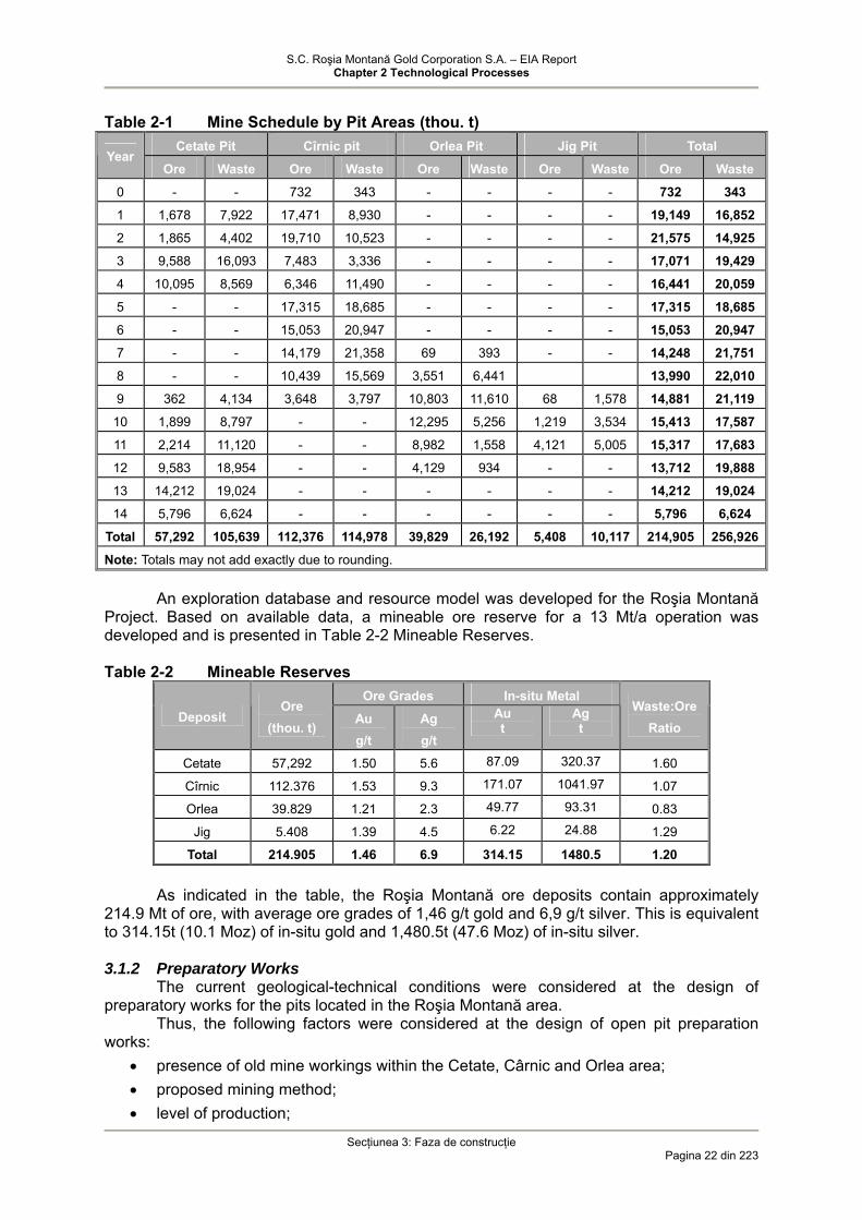
Table 2-1 describes a preliminary schedule of the preparatory – mining activities. In addition, the site location plans for Project years 0, 7, 14 and 17, are given in Exhibits 2.3, 2.4, 2.5 and 2.6, respectively.
Four open pits (Cetate, Cîrnic, Orlea, and Jig pits) will be mined. The four pit areas are areas within a single mine operation, which will feed ore to the process plant. Mining will commence in the Cîrnic open pit in year 0 and will be carried out until year 9. The Cetate pit will be mined between year 1 and year 4, followed by a ceasing of operations which will recommence in year 9 until the end of mining in year 14. Mining at Orlea pit will be initiated in year 7 of the operation until year 12, while Jig pit will be mined between year 9 and 11.
S.C. Roşia Montană Gold Corporation S.A. – EIA Report Chapter 2 Technological Processes
Secţiunea 3: Faza de construcţie
Pagina 22 din 223
Table 2-1 Mine Schedule by Pit Areas (thou. t)
Cetate Pit Cîrnic pit Orlea Pit Jig Pit Total Year
Ore Waste Ore Waste Ore Waste Ore Waste Ore Waste
0 - - 732 343 - - - - 732 343
1 1,678 7,922 17,471 8,930 - - - - 19,149 16,852
2 1,865 4,402 19,710 10,523 - - - - 21,575 14,925
3 9,588 16,093 7,483 3,336 - - - - 17,071 19,429
4 10,095 8,569 6,346 11,490 - - - - 16,441 20,059
5 - - 17,315 18,685 - - - - 17,315 18,685
6 - - 15,053 20,947 - - - - 15,053 20,947
7 - - 14,179 21,358 69 393 - - 14,248 21,751
8 - - 10,439 15,569 3,551 6,441 13,990 22,010
9 362 4,134 3,648 3,797 10,803 11,610 68 1,578 14,881 21,119
10 1,899 8,797 - - 12,295 5,256 1,219 3,534 15,413 17,587
11 2,214 11,120 - - 8,982 1,558 4,121 5,005 15,317 17,683
12 9,583 18,954 - - 4,129 934 - - 13,712 19,888
13 14,212 19,024 - - - - - - 14,212 19,024
14 5,796 6,624 - - - - - - 5,796 6,624
Total 57,292 105,639 112,376 114,978 39,829 26,192 5,408 10,117 214,905 256,926
Note: Totals may not add exactly due to rounding.
An exploration database and resource model was developed for the Roşia Montană Project. Based on available data, a mineable ore reserve for a 13 Mt/a operation was developed and is presented in Table 2-2 Mineable Reserves. Table 2-2 Mineable Reserves
Ore Grades In-situ Metal Deposit
Ore (thou. t) Au
g/t Ag g/t
Au t
Ag t
Waste:Ore Ratio
Cetate 57,292 1.50 5.6 87.09 320.37 1.60
Cîrnic 112.376 1.53 9.3 171.07 1041.97 1.07
Orlea 39.829 1.21 2.3 49.77 93.31 0.83
Jig 5.408 1.39 4.5 6.22 24.88 1.29
Total 214.905 1.46 6.9 314.15 1480.5 1.20
As indicated in the table, the Roşia Montană ore deposits contain approximately
214.9 Mt of ore, with average ore grades of 1,46 g/t gold and 6,9 g/t silver. This is equivalent to 314.15t (10.1 Moz) of in-situ gold and 1,480.5t (47.6 Moz) of in-situ silver.
3.1.2 Preparatory Works
The current geological-technical conditions were considered at the design of preparatory works for the pits located in the Roşia Montană area.
Thus, the following factors were considered at the design of open pit preparation works:
• presence of old mine workings within the Cetate, Cârnic and Orlea area; • proposed mining method; • level of production;

S.C. Roşia Montană Gold Corporation S.A. – EIA Report Chapter 2 Technological Processes
Secţiunea 3: Faza de construcţie
Pagina 23 din 223
• vertical development of the geological resource which may be mined between +1080 metres and +480 metres elevation (lowest level down to which the resources/reserves have been estimated);
• site morphology and physical-mechanical characteristics of the rocks included in the geological composition of the deposit;
• amount of works required for open pit development and associated costs, as well as environmental reconstruction costs.
• maximum mining depth. The Roşia Montană deposit will be opened by open pit mining, the required
preparation works will include provision of access to the pit benches, i.e. access roads to the benches located above the local erosion level and trenches for the in depth benches.
A total of 4 main areas were identified based on the spatial distribution of the gold and silver resources where opportunity exists for the development of large scale open pits i.e. Cetate (Cetate and Carpeni), Cîrnic (Cîrnic and Cîrnicel), Orlea and Jig.
Preparatory works and mining will commence in the Cîrnic open pit. The Cîrnic pit shown on Drawing 1 is almost circular in shape extending E-W over
900m and N-S over 1100m. The pit will be opened with inner semi-trenches where two traffic lane haulage roads will be constructed to ensure access of heavy machinery and ore transportation.
Te semi-trench will be excavated from the main access road constructed on the southern slope of the Cîrnic Massif up to + 1080 m maximum elevation.
In the first stage mine benches located between El. +1080 m and +1020 m will be developed. For the benches at El. + 1020 m and + 930 m the deposit will be opened with semi-trenches excavated from the access road constructed in the southern part of the massif.
Mining works for bench construction will comprise excavation of a spiral semi-trench starting at the southern part of the pit and continuing up to El. + 660 m (east flank) and El. + 810 m in the western part of the pit, repsectively.
The Cetate pit is oval in shape with length of 1200m along the N-S centerline and width of 700 m along the E-W centerline. The Cetate pit will be initially developed in the southern part, between El. + 920 m and El. + 880 m via a semi-trench where the main 2 way haulage roads are constructed.
Opening of benches located between El. + 830 m and El. + 820 m will be achieved by semitrenches excavated from the access road bordering the western part of the pit.
The lower benches will be opened by the continuation of the main semitrench which extends down to El. 790 m and via a spiral haul road extending down to the base of the pit at the final floor elevation of + 650 m.
In the northern part of the Cetate pit, the development works will include excavation of a semitrench from the access road at bench El. + 760 m and a spiral semitrench starting at El. +760 m and extending along the eastern slope following the pit perimeter down to El. 680m at the final pit floor elevation (Figure 2.1).

S.C. Roşia Montană Gold Corporation S.A. – EIA Report Chapter 2 Technological Processes
Secţiunea 3: Faza de construcţie
Pagina 24 din 223
Figure 2.1. Mining Works
Fig. nr. 1
Cetate Pit
Cîrnic Pit
Orlea Pit
Jig Pit

S.C. Roşia Montană Gold Corporation S.A. – EIA Report Chapter 2 Technological Processes
Section 3: Construction Phase
Page 25 of 223
Orlea pit will be accessed via a haul road constructed in the western part of the Cetate pit. The pit will be opened with inner semi-trenches.
Initially, the benches between El. +870 m and El. +750 m will be successively opened with main semitrenches constructed from the southern and south-eastern flanks of the pit.
Following mining of the upper part of the massif, the resources located in the +740 m and +690 m range depth will be opened with a semitrench excavated from the southern part of the pit, which extends down the western pit flank to El. +690 m. Two spiral semitrenches will be excavated from the main semitrench in order to open the benches below El. +690 m, which extend in the south-eastern part of the pit to the final pit floor elevation (+660m) and the north-western part to the Orlea pit final floor elevation (+660m) (Figure 2.1).
The Jig pit will be opened via the surface haul road splitting off the Orlea pit access road and following the Roşia valley up to the pit site. Mining of the Jig pit will consist mainly of excavations in the hill side, the pit floor is located SE at El. +850 m and NW at El. +820 m.
Initially, the resources located between El. + 1020 m and + 900 m will be accessed, the development mining works being located on the S and W pit flank.
The benches located between El. + 1020 m and + 900 m will be opened with a joint outer semitrench constructed from the main service road located on the southern and western flank.
As the mineralised zone below El. + 900 m consists of ore bodies striking SE – NW separated by waste zones, the opening at depth will be carried out separately for each zone via spiral semitrenches.
The final pit will be oval in shape and will extend 900m E-W and 350m N-S, with floor elevation of + 840 m in the western part, + 850 m in the central part and + 870 m in the eastern part (Figure 2.1).
Topsoil will be removed from each site by stripping using bulldozers, loading using front-end loaders and truck haulage to the topsoil stockpiles to be re-used as part of the reclamation and closure operations.
3.1.3 Development of quarries for construction materials (La Piriul Porcului
Sandstone Quarry; Sulei Andesite Quarry) A number of potential quarry sites have been investigated as sources of aggregate
for construction of the TMF dam and water management dams as well as for earthworks and concrete preparation. Two quarry sites (Exhibit 2.9) are planned for development unless alternatives can be secured at an equal or more favourable price. It is expected that some material suitable for construction will be obtained from the pre-strip excavation for the Cetate and Cîrnic open pits.
Initial estimates indicate that in order to supply the necessary quantities of aggregate an estimated area of 10 ha must be cleared and grubbed; in addition, over 1 km of access roads must be constructed from existing roads.
The preparation and opening of the two quarrie: La Pîrîul Porcului Sandstone Quarry and Sulei Andesite Quarry during construction will be detailed in the Exploitation Permits currently prepared by IPROMIN Bucharest.
3.1.4 Waste Rock and Low-grade Ore Stockpiles
Site preparation for development of the offsite Cetate and Cîrnic waste rock dumps involves the following operations:
• decaparea solului vegetal, încărcarea şi transportul la depozitul de sol vegetal, pentru utilizarea ulterioară la lucrările de reconstrucţie ecologică;topsoil stripping, loading and transport to the topsoil stockpile for further use in the environmental reconstruction works;
• scarificarea şi compactarea fundamentului, pentru formarea unui strat semi-permeabil, limitându-se astfel posibilităţile de poluare a acviferelor freatice;Scarification and compaction of the foundation to create a semi-impervious

S.C. Roşia Montană Gold Corporation S.A. – EIA Report Chapter 2 Technological Processes
Section 3: Construction Phase
Page 26 of 223
layer under the waste rock stockpiles and thus minimise the potential for water table contamination;
• depunerea, nivelarea şi compactarea unui strat de dacit puternic silicifiat cu grosimea de circa 1 m la baza haldelor de steril, acesta având rolul de a reţine particulele de material solid antrenate de curenţii de şiroire (strat drenant);deposition, leveling and compaction of a strongly silicifiated 1 m thick dacite layer at the base of the waste rock dumps designed to retain the solid particles carried off by run off water (drainage layer); As most of the waste material resulting in the first mining phase will be used for the
construction of the Corna dam limited volumes of waste will be stockpiled in the first three years of operation.
The stockpile construction method prior to site preparation is not described (either twinning benches or the natural slope angle will be used). The dump construction method will impact on the overall stability of stockpiles and will be described in detail in the detailed studies.
There is not enough information with respect to the geotechnical studies conducted over the Cetate and Cîrnic site locations. Additional boreholes are proposed for execution in the detailed design stage in order to obtain actual geotechnical characteristics of the site proposed for the construction of the two waste rock dumps (see Conclusions in Appendix M5).
The low-grade ore stockpile will be located north of the processing plant, between the Cetate Waste Rock Stockpile on the west and the Cetate Pit on the east. It will be sized to accommodate the entire volume of extracted low-grade ore (some 32 Mt). The perimeter of the stockpile will be provided with seepage collection channels – ditches. They will report to the ARD treatment plant.
3.1.5 Tailings Impoundment 3.1.5.1 TMF Site Characteristics
A series of investigations were carried out in view of developing a detailed understanding of the TMF site characteristics which provided information on the geology, hydrogeology and geotechnical conditions of the region and location of TMF dams (main and secondary dams).
Geology Regional Geology
The Roşia Montană Tenement is located within the Eastern Belt of the South Apuseni Mountains.
The reginal rock consists of the following: • fundamentul metamorfic străbătut de granitoide;metamorphic basement traversed by
granitoid rocks; • flişul (depozite sedimentare de şisturi argiloase, nisipuri şi conglomerate);flysch
sequence (sedimentary deposits of shale, sand and conglomerate); • ofiolite (roci vulcanice mafice) urmate de stratul de lavă.ophiolite sequence (maphic
volcanic rocks) overlain by the lava layer.
Surficial Geology Overburden soils in the Corna and Roşia Montană Valleys consist of three
predominant soil types [1]; • aluviuni;alluvial deposits; • coluviuni;colluvial soils; • aflorimente de alte roci.outcrops of other types of rock;
The unconsolidated materials consist of Quaternary alluvial deposits along the valley floors and colluvial soils along the valley slopes. The alluvial deposits are up to 12 m in
S.C. Roşia Montană Gold Corporation S.A. – EIA Report Chapter 2 Technological Processes
Section 3: Construction Phase
Page 27 of 223
thickness and contain a wide variety of soil types ranging from silty clay with intercalation of sand, to gravel and boulders being particularly restricted to the base of the valley.
The colluvial/residual soils on the valley slopes are typically 2 to 5 m thickness. At the upper part, over a height of 15 cm – topsoil followed by silty clay and sandy clay, sand and gravel can be found. The predominant rocks found in the valley watersheds are marl and sandstone. Harder ridges with East-West orientations dominated by marls interpreted as thicker sandstone units occur locally. Probably this flysch unit suffered intense deformations almost throughout the area, the results could be seen as outcrops.
A remarkable "slope fracture" occurred on one of the ridges that separates the Roşia and Corna Valleys. Marls outcrop at the base of the fracture, which are rocks typical of flysch unit.
A 10-50 m sequence of andesite pyroclastics, volcanic ash and andesites can be noticed above the fracture.
Geological Basement
The area consists largely of late Jurassic-Cretaceous sedimentary deposits (205 - 65 million years in age) predominately black shale with various degrees of sandstone interbedding. The formations consist of:
• Upper Aptian (ap2) - Lower Albian (al1), comprising argillaceous marly schists with fine argillaceous – marly gritty clay intercalations;
• Upper Cretaceous -Maastrichtian (ma) represented by a complex of interbedded micaceous sand in flysch facies. The bedrock across the Corna Valley is the flysch series of the Maastrichtian on the
left bank reposing over the flysch sequence of the Albian/Aptian on the right bank in a stratigraphic unconformity.
Drawing 2.50 illustrates a schematic geological cross section through the Corna Valley. There is a difference in age between the two sequences, the right bank material being 30 years older than the left bank material.
The flysch facies is a consequence of the competence and incompetence of the tectonic alteration, faulting and shear deformation of shale with sand and conglomerate intercalations.
Within the TMF site, the shale unit dips 30 to 55 degrees in a southerly direction, towards the left bank.
In general, the waste rock within the tenement consists of the following: • Black shales - this Cretaceous-aged sedimentary sequence, also described as flysch
or argillaceous marl schist, typically consists of interbedded shale and fine to medium grain sandstone. The rock is characterised by calcite veins within the sandstone, variable bedding orientation, and occasional weak and/or brecciated zones. This unit comprises the bedrock typical of much of the Corna valley and surrounding valleys, outside the mineralised zones.
• Vent breccia - in the form of microconglomerates and tuffaceous grits, described as medium grain volcaniclastics (i.e., sedimentary rock composed mainly of particles of volcanic origin) from the late Tertiary period (Neogene). The vent breccias are generally massive.
• Black breccia is a dark-brown to black rock occurring in the southern part and between Cârnic and Cetate bodies. The breccia has a matrix of black shale and clastic dacite, cretaceous sedimentary rocks and basement crystalline rocks.
• Andesite pyroclastics and lava flows. This rock was mapped in several locations at the Corna valley origin and along the ridgeline between Corna and Saliste valleys. Extensive outcrops of the andesite occur on the east and north ridges bordering the upper Rosia Valley. While not considered a primary rock type, there are local blocks of limestone outliers
(olistolites) that were observed just upstream of the TMF embankment centerline and near

S.C. Roşia Montană Gold Corporation S.A. – EIA Report Chapter 2 Technological Processes
Section 3: Construction Phase
Page 28 of 223
the right abutment. Based on drilling and site-specific mapping, the limestone blocks are not considered to be rooted and no karst formation is expected.
Structure
An airborne magnetic survey was conducted over the Roşia Montană – Bucium survey block (RSG, 2001). An interpretation of the survey results revealed numerous linear features that were interpreted to be faults. The survey results revealed two dominant conjugate sets of faults trending north-northwest and east-northeast. An older, north-south trending set of faults can also be traced and appeared to be associated with mineralisation. An inclined borehole was advanced across one of the north-northeast interpreted faults in the lower part of the valley to a depth of 90 meters (along the incline) with the objective of defining the presence and condition of this potential fault. A shear zone consisting of coarse-grain breccia (different from the rock above and below) was encountered and was identified as likely being a minor fault.
Hydrogeology
The Roşia Montană mining region is located near the headwaters of the Corna, Saliste and Roşia Valleys. The mine site is located within or near the Roşia, Corna and Săliştei Valley watersheds.
The Corna Valley watershed includes, within the Roşia Montană Project, the waste rock dump, Cârnic waste drainage holding pond, TMF also including the secondary containment dam. The Corna stream flows to the southwest into the Abrud River.
The watershed dividing the Corna Valley basin from the Roşia Valley basin will be located on the southern boundary of the Cetate and Cârnic pits. Based on the existing topography it appears that - partly - the watershed was running through the middle of the southern part of the Cetate and Cârnic pits.
Due to the development of the current pits, the watershed was moved towards the southern boundaries of the pits.
The Sălişte Valley watershed will include the south-western part of the ore processing plant site. Following the plant site construction the water will flow to the Roşia Valley basin.
The Sălişte Valley flows to the west including the tailings dam currently operated by the Roşia Montană mine.
The hydrogeology of the area was evaluated through an extensive drilling program that was conducted at the site by SNC Lavalin in 2003 [6] and was further developed by MWH in 2003 with new boreholes, flow measurement stations and piezometers [7].
Water levels were measured in the piezometers by RMGC on a biweekly basis since April 2002. These water level data were used to generate a potentiometric surface map of the unconfined water table (Appendix A4 a Engineering Review Report). The hydrographs for the period between April 2002 and May 2004 were developed using these data.
Appendix A4 "SURFACE WATER AND GROUNDWATER ASSESSMENT REPORT, MWH 2005 " [8] to the Engineering Review Report contains detalied information on the regional hydrology and hydrogeology.
Surface water and groundwater reflect the hydrogeologic characteristics of underground deposits. The area is characterised by the presence of springs and valley slope runoff. The spring and runoff origin is uncertain, however it appears they are the result of differences in permeability. There are two situations:
• higher permeability of the pyroclastic and andesite deposits constrained by a lower permeability of the colluvial soils;
• higher permeability of the colluvium deposits constrained by a lower permeability of the gritstone and marl layers. The primary stratigraphic units and their typical hydrogeologic properties are
summarised in Table 2-3.

S.C. Roşia Montană Gold Corporation S.A. – EIA Report Chapter 2 Technological Processes
Section 3: Construction Phase
Page 29 of 223
Table 2-3 Hydrogeologic Properties Stratigraphic Unit Assignment Hydrological Characteristics Alluvium (Minor and major streambed)
Deposits of silty clay and sandy clay with significant and variable distribution zones of gravel and cobbles. Includes layers of gravel and clean sand located in the minor streambed. They have a width of 10-80 m and thickness of up to 12m.
Clean sand and gravel layers act as local aquifers. The mean hydraulic conductivity is relatively high in the range of 2x10⁻⁶ to 3x10⁻⁴ m/s
Colluvium (with soil) (On the valley hillsides)
First silty sand and silty clay with small amounts of sand and gravel with thickness of 3 to 10.5m.
Low water storage capacity Hydraulic conductivity approximately 1x10⁻⁸ m/s
Upper bedrock (marl) Sandstone interbedding, shale, clay highly altered and fractured for the first 40m. Located beneath the alluvium and colluvium.
Generally water bearing only through fracture network and has only low regional capacity. It may be moderately water bearing through the bedding planes. The hydraulic conductivity values in the range of 1x10⁻⁷ la 1x10⁻⁶ m/s
Upper bedrock (marl) Interbedding of marl, gritstone with minor intervals of silty clay and breccia increasingly competent with depth
Low capacity. Hydraulic conductivity in the range of 6x10⁻⁹ and 1x10⁻⁷ m/s
Dacite and Andesite Generally competent bedrock. Low capacity. No piezometers were installed in this rock type. Hydraulic conductivity <1x10⁻⁷ m/s
Volcanic breccias and black breccia
Typical soft rocks Limited flow may occur through fractures or naturally formed zones of enhanced permeability Low hydraulic conductivity <1x10⁻⁷ m/s
A hydroghaph analysis indicates that water levels are generally seasonally stable. The period of record for water levels measured in the piezometers is relatively short
and may not represent longer-term changes that may occur during drought or wet years. Data indicates, however, that the water level in the piezometer has stabilised and is
representative of the Project footprint conditions. The flysch unit occurring within the TMF site in the Corna valley was differentiated in
two types: upper bedrock and lower bedrock. The bedrock types were characterised with respect to the differences in the hydraulic conductivity, rock quality designation (RQD) (%), the percentage used for the dam core and borehole parameters observed during their completion and water pressure measurement - Drawing 2.40 and 2.41.
A highly weathered and fragmented intercalation occurs within the upper bedrock in the northern hillside of the valley.
This intercalation is most likely associated with the presence of the „Lower Albian” and „Upper Aptian” formations in the northern hillside. The southern hillside appears less weathered and fragmented.
The mean hydraulic conductivities, upper bedrock is in the range of 1x10⁻⁶ to 8x10⁻⁷ m/sec.
In the area under investigation the groundwater follows the topography of the Corna Valley.
Water level data collected from April 2002 to January 2004 in the piezometers installed in the Corna Valley (Appendix 4 Engineering Review Report) [8] indicate that, in general, water levels are seasonally stable.
Water levels in some piezometers showed some seasonal variation. Hydraulic gradients within Corna Valley - within and near the TMF footprint -range from 0.08 to 0.40. The gradient is lower along the axis of the valley (e.g. near the proposed dam), while the gradient is higher on the dam abutments.
The water table map also indicates that the Corna Valley flow increases downstream (i.e., receives water from the zone of saturation/groundwater) throughout the year during normal and wet precipitation years.
A comparison of the water levels in piezometers indicates that in general there is a response (up to 1 meter) in some piezometers to short-term precipitation events (Appendix A4 Engineering Review Report). For example, a rise in water level of up to one meter was
S.C. Roşia Montană Gold Corporation S.A. – EIA Report Chapter 2 Technological Processes
Section 3: Construction Phase
Page 30 of 223
observed in piezometer 02DH-C2-06/5 during an increase in flow of up to 0.3 m3/s. Conversely, piezometers 02DH-C2-12/12 and 02DH-C2-12/29 apparently showed no response to the same precipitation events. However, the lack of response in some piezometers may be a function of the time lag between the precipitation event and when the water level was measured in the piezometer (i.e., the response in the well had occurred and dissipated by the time the water level was measured). It however may be a function of the short precipitation time which can not affect the groundwater level.
These data also indicate that the stream and alluvial groundwater are generally in direct connection with each other. In addition, as there are no significant sealing layers in the alluvium it can be assumed that the surface waters are also in direct connection with the groundwater within the colluvium and bedrock (i.e. this system forms a hydrostratigraphic unit).
A significant feature of the groundwater flow system is the presence of a downward vertical hydraulic gradient in the vicinity of the initial TMF Dam alignment. These gradients were measured by comparing water levels in 22 pairs of nested piezometers located in this area. The downward vertical hydraulic gradient is somewhat higher below the right abutment (0.6, downward), compared to the left abutment (0.4, downward), possibly due to the different bedrock formations at these locations. The vertical gradients along the Corna Valley axis were as follows:
• 0.17 (downward) upstream of the initial TMF Dam alignment; • -0,01 (upward) to 0,04 (downward) in the Tailings Dam centreline; • -0.01 (upward) to 0.3 (downward) near the Secondary Containment Dam centerline.
The location of the hydrologic and geotechnical investigation works is shown on Drawing 2.39-02 and borehole profiles are illustrated on Drawing 2.40-03.
Geotechnical Conditions
The following discussion on the geotechnical conditions beneath the dam location in the Corna Valley is based on previous work conducted by SNC-Lavalin Consultants and supplemental investigation work by MWH [6; 7; 9] focused on:
• defining and evaluating the hydraulic conductivity profiles; • drilling, sampling and testing the “clay matrix” or soft rock layer; and • delineating, sampling and evaluation of the local, non-acid generating construction
materials (rocks). Borehole and testing locations are shown on Drawing 2.39. The cross-sections through the TMF are shown on Drawings 2.40 and 2.4. It should be noted that during the optimisation study which followed the field
investigations the TMF main dam centerline was moved approximately 250 m upstream and the secondary containment dam centerline was moved approximately 400 m upstream.
TMF Main Dam
Boreholes 03DH-C2-01, 03DH-C2-02, 03DH-C2-02A, 03DH-C2-03, 03DH-C2-07 şi 03DH-C2-07A were drilled along the dam alignment. A cross-section through the TMF and the borehole locations are shown on Drawing 2.40. The followings are shown on the cross-section: rock core recovery (REC in %), rock quality designation (RQD) and hydraulic conductivity given in Lugeon units.
Observations from boreholes 03DH-C2-01, 03DH-C2-07 and 03DH-C2-07A located along the Corna Valley creek bed indicate that the alluvial deposits are up to 12 m in thickness. The "n" values of the Standard Penetrometric Test (SPT) vary between 4 and 40 depending on the particle size. Colluvial soils are not present along the valley floor. The SPT values increase with depth even if less dense intervals were observed.
In the test pits excavated within the TMF footprint, the alluvial deposits contain a wide variety of soil types ranging from silty clay as main component or as a matrix of coarse sand, fine to coarse gravel and cobbles. The predominant soil types are cohesive in nature
S.C. Roşia Montană Gold Corporation S.A. – EIA Report Chapter 2 Technological Processes
Section 3: Construction Phase
Page 31 of 223
increasingly competent with depth. The competence of the materials exposed during test pit excavation varied from compact to hard.
The boreholes located outside the valley floor intersected colluvial soils with thickness ranging from 3 to 10 m (on the north hillside and south hillside, respectively). The difference in thickness is the result of different geological units as shown above. The colluvial/residual deposits consist mainly of fines with occasional mix of coarse sand and cobble sizes. The coarse sand typically consists of sandstone which is more resistant in time to weathering than shale due to its composition of quartz and feldspar particles and cementation with silica and carbonate.
Following the laboratory tests the colluvial material was classified as silty clay of medium to low plasticity. The undrained shear strength of the material with natural moisture content, measured with a qualimeter, vary between 75 kPa and 225 kPa (SNC, 2002) [6].
The bedrock across the Corna Valley within the TMF site is a sequence of competent and incompetent foliated shale dipping south, towards the left bank, with intercalation of sandstone, breccia and weaker foliated shale. The frequency of sandstone intercalations increases below the 50m depth.
The core recoveries and sample rock quality designation have an average variability index between <10% and 100% and from 0 to 100%, for boreholes drilled with the valley axis (03DH-C2-01, 03DH-C2-07 şi 03DH-C2-07A). The boreholes located on the right slope (03DH-C2-02 and 03DH-C2-02A) returned very good to excellent recoveries (between 60% şi 100%) with a few recoveries under 40%. However, the rock quality following the measurements using the rock quality designation (RQD) is invariably 0 with some intervals where RQD ranges from 10% to 40%. The boreholes located on the left slope(03DH-C2-03 and 03DH-C2-03A) show a significant increase in the rock quality reflected by the higher core recovery and RQD. The rock quality on the left bank exceeds 50% at a depth of 11m and 70% at a depth of 25 m. The core recovery varies around 80% with 100% recoveries at depths between 25 m and 50 m.
Rock strength as per the results of field tests and previous triaxial testing presented by GRD Minproc Ltd and Knight Pieshold 2001 [10] shows a significant variation of the rock strength from soft to hard (5-100MPa) (Bieniawski 1989). The areas with soft and very soft rock and low core recovery and RQD are associated with tectonic degradations and fragmentation.
The water table is found at the surface in the water-course bed at a depth of 12 - 15.31 yd on the left valley slope and 14 - 19.69 yd on the right slope.
Secondary Containment Dam Site
Boreholes 03DH-C2-04, 03DH-C2-05 and 03DH-C2-06 were drilled along the Secondary Containment Dam centerline. Drawing 2.41 illustrates the central section through the Secondary Containment Dam and borehole locations. The following are shown on the cross-section: rock core recovery (REC in %), rock quality designation (RQD) and hydraulic conductivity given in Lugeon units.
Observations from the boreholes downstream of the TMF in the Corna Valley stream bed show that the thickness of alluvial deposits reaches the maximum thickness of 9m in the creek bed section and progressively decreases towards the slopes. The "n" values of the Standard Penetrometric Test (SPT) generally increase with depth, and vary from 3 at the surface to 20 depending on the particle size. SPT values increase with depth even if intercalations are rarely observed. Higher "n" values were also obtained in areas where coarse grained fragments occur.
The bedrock was intercepted at a depth of 9 m in the flood plain area, 3m on the right slope and 11 m along the left slope. The bedrock consists of foliated shale. Recoveries along the valley axis are generally 0% in the first 10 m below the surface increasing to 40% or 60% at a depth of 25 m or to considerably more than 80% at depth. Recoveries and RQD for the 03DH-C2-05 borehole located on the right slope indicate a wide scatter down to the total depth of 50 m. Although at the depth of 30m a general increase of the recovery and RQD was recorded, random intervals with low recovery and RQD are still found. As noted above, the different formations and age are responsible for the significant differences in rock

S.C. Roşia Montană Gold Corporation S.A. – EIA Report Chapter 2 Technological Processes
Section 3: Construction Phase
Page 32 of 223
quality. The water table was generally encountered within the valley floor between 12 and 14 meters below ground surface on the left valley slope and between 14 and 18 on the right slope.
Seismicity
A review of the regional seismicity of Romania and adjacent regions was presented in the Definitive Fezability Study [11].
The seismicity within the Western Carpathian Mountains is moderate with earthquakes occurring at shallow depth. The majority of these earthquakes are magnitude 6 to 6.5.
The most active area in terms of seismic activity is Vrancea with earthquakes occurring at depths of 50-170 km. The distance between Vrancea and Roşia Montană is some 275 km.
Another active seismic area is found in the Timis County where shallow depth earthquakes occur of low or moderate magnitude (M4 to M6). The biggest earthquake recorded in the Timis County occurred in 1887 and was of magnitude M7.
In 2002 an earthquake of 4.2 magnitude on the Richter scale was recorded with the hypocenter at approximately 100 km south of Roşia Montană.
Professor Stematiu from the Technical University of Bucharest reviewed the seismic hazard analysis prepared by DFS (KP-2001b). The summarised results are presented in Table 2-4. Table 2-4 Seismic Hazard Analysis
Return Period Probability of Exceedance (%)2
Maximum Acceleration (g)1&3
Intensity (MM) 1&4
1:50 29,1 0,035 V 1:100 15,7 0,050 VI 1:200 8,2 0,062 VI 1:475 3,5 0,082 VI-VII 1:1000 1,7 0,102 VII 1:2000 0,8 0,115 VII 1:5000 0,3 0,134 VII-VIII 1:10000 0,2 0,151 VIII
Notes: 1 - Data from (Knight Piésold 2001b, Table 2.8) 2 - Probability of Exceedance Calculated for a design life of 16 years
L
T1T1q ⎟
⎠⎞
⎜⎝⎛ −
−=
where: q - probability of exceedance; T - return period in years L - design life in years 3 - Maximum accelerations for bedrock 4 - Modified Mercalli Intensity
It was determined that a Maximum Credible Earthquake (MCE) of magnitude 8.0, causes a maximum bedrock acceleration of 0.14 g.
In the stability analysis of the Corna Dam the following values were used: OBE = 0.082g (Operation Basis Earthquake), Maximum Design Earthquake (MDE) and Maximum Credible Earthquake (MCE): MDE = MCE = 0.14g; the analysis is presented in Section 3.1.5.3.
3.1.5.2 TMF Design TMF design Criteria
The TMF design comprises two phases: • the first phase corresponds to the construction phase of the other components of the
Roşia Montană Project;

S.C. Roşia Montană Gold Corporation S.A. – EIA Report Chapter 2 Technological Processes
Section 3: Construction Phase
Page 33 of 223
• the second phase overlaps the operational phase, due to the following: the main dam is constructed continuously by successive raises; the TMF basin footprint and main dam footprint are continuously prepared based on the raise stages; the tailings distribution system is modified with each raise; the guard ditches on the slopes are reconstructed with each dam raise; lagoons for semi-passive treatment of seepage water will be constructed in the second operational phase based on research conducted during this period on the treatment technology to be applied for this type of water. The starter dam, secondary containment dam and the other facilities required to
commission the TMF concurrently with the process plant commissioning are constructed in the first phase.
The design criteria for the TMF basin, Secondary Containment Pond and Corna dam are as follows:
• The TMF pond provide a full containment of all flood events, including the Probable Maximum Flood (PMF) throughout the project life; The tailings watershed, including the Cârnic waste rock stockpile, will be
approximately 689 hectares and it is composed of four main land-use components: tailings pond, tailings beach, Cârnic waste rock stockpile and undisturbed land.
From the flood flow direction standpoint the operational parameters of the TMF basin and SCS sump are consistent throughout the project life. However, the size of the TMF, the tailings deposit volume and available flood storage volume will change during the project life until closure.
S.C. Roşia Montană Gold Corporation S.A. – EIA Report Chapter 2 Technological Processes
Section 3: Construction Phase
Page 34 of 223
The TMF parameters show that from the flood storage capacity standpoint the critical period will be immediately prior to the first raise of the tailings dam, assuming that the operating level in the TMF is 95% and a PMF event occurs. The probability of the PMF occurring during this very short time horizon before the first TMF raise is very small and it can be assigned a probability of approximately 1 to 10 million which statistically corresponds to an event with a return period of 12 million years. [5]
After the short critical period at the year 1.25 of the mine life the dam will be raised and the TMF pond storage would be sufficient to accommodate an increasing flood volume until year 14 when the flood storage capacity decreases slightly toward the end of operations.
• The cofferdam for the starter dam must be designed to manage a 24-hour rainfall event with a return period of 1:10 years;
• The starter dam crest elevation must be designed to provide tailings storage and water management (store 95th percentile of decant pond and PMF volume) for the first 15 years of operation;
• The ultimate crest elevation of the tailings dam must provide storage for 215 Mt of tailings, which incorporated a 34 Mt contingency and also provides adequate capacity for management of water from two consecutive PMPs;
• The water pond retained by the starter dam and tailings dam has sufficient capacity above the maximum normal operating level to store the runoff volume from two 24-hour PMF event;
• An emergency spillway is provided to safeguard the dam in the event of unexpected climatic conditions or operational difficulties. The TMF spillway design is based on the spill from a 10-year flood;
• Based on Romanian standards and risk rating categories, the SCD is classified as Class I of Importance and Category B, respectively.
• Supernatant water and runoff reporting to the tailings pond are recycled for use in the process plant;
• Use of waste rock for dam raises up to the maximum elevation; • The minimum factors of safety for static loading conditions during starter dam
construction and during subsequent dam raising construction are 1.3 and 1.5, respectively.
• Seismic loading is based on the 1:475 year design earthquake (a=0.082 g) for end of starter dam construction and the maximum credible earthquake event (a=0.14 g) for subsequent dam raising construction and for closure;
• A minimum factor of safety of 1.1 applies for seismic loading.
The Secondary Containment System Sump is designed according to the criteria listed below:
• The water pond retained by the SCD has sufficient capacity above the maximum normal operating level to store the runoff volume from a 24-hour, 100-year event;
• Seepage and runoff water collected in the SCS sump is pumped back to the tailings pond;
• An emergency spillway is provided to safeguard the dam in the event of unexpected climatic conditions or operational difficulties designed for the 1,000-year, 24-hour storm event.
• the SCS pond has sufficient capacity to store the runoff volume from a 24 hour rainfall event with a return period of 100 years;
S.C. Roşia Montană Gold Corporation S.A. – EIA Report Chapter 2 Technological Processes
Section 3: Construction Phase
Page 35 of 223
The Secondary Containment Dam is designed according to the criteria listed below: • Based on Romanian standards and risk rating categories, the SCD is classified as
Class I of Importance and Category B, respectively. • Inert and non-reactive materials are used for the dam construction; • The SCD is designed with a minimum factor of safety of 1.3 for end of construction,
1.5 during operation and closure. A minimum factor of safety of 1.1 applies for seismic loading in conjunction with pseudo-static loading.
• Seismic loading is based on the 1:475-year design earthquake (a = 0,082g) for end of construction and the maximum credible earthquake event (a = 0,14g) for operation and closure.
• The 27 m wide crested emergency spillway is designed to contain the flood from the events with the following return periods:
• 500 years, spill is on the order of 0.6 m3/s; • 1000 years, spill is on the order of 2.5 m3/s; • PMP, spill is on the order of 24.7 m3/s [5].
Construction Data. Construction Stages. The tailings impoundment will be formed by an embankment with different
permeability zones that will be built in phases n order to provide appropriate containment of the tailings and satisfy the design and operational criteria of the TMF. The TMF starter dam and Secondary Containment Dam will be constructed out of inert non-ARD materials.
Subsequent raises of the TMF dam will be constructed with waste rock with potential to generate ARD runoff which will be captured behind the Secondary Containment Dam and the water will be managed based on the water quality characteristics, as follows: if the Romanian discharge standard are met, the water will be released into the Corna Valley, if the discharge requirements are not met the water will be pumped back to the TMF decant pond.
The use of waste rock to construct the dam raises beyond the starter dam serves two purposes: first, it allows storage of waste rock without creating a new or expanded waste rock stockpile; second, it provides a structural material for constructing the TMF dam without expanding existing borrow areas or creating a need for a new borrow area.
The starter dam will form the first stage before operations begin and subsequent stages will be constructed during operations. The starter dam will be of sufficient height to provide tailings storage and appropriate additional water management capacity for the first 15 months of operation; the starter dam will act primarily as a water retention dam during this period. Therefore, the starter dam will incorporate a low permeability core, filter/transition zones, and rockfill shells.
Prior to starter dam construction, all vegetation and topsoil will be removed within the footprint of the starter dam and containment basin. Vegetation will be disposed of outside the limits of the TMF basin and topsoil will be stockpiled for use during closure and reclamation. The surface of the colluvial layer will be compacted to achieve a permeability of approximately 1x10⁻⁶ cm/sec. The compacted layer is intended to provide a barrier layer to reduce seepage from the TMF basin.
The extent of the basin preparation will be extended with the construction of each raise. In areas where the colluvial layer has been eroded or is not present, excess colluvial material within the basin will be used to cover these areas. The placed material will be compacted to achieve that same permeability as the native materials.
The low permeability core extends to the bedrock surface with appropriate foundation treatment, including contact grouting. The starter dam will initially store water to about El 697 m (1,500,000 m3 of water storage) at start of operations. The tailings will initially be completely submerged and water will be impounded against the dam above the level of the submerged and saturated tailings. The starter dam will have to perform as a water dam until
S.C. Roşia Montană Gold Corporation S.A. – EIA Report Chapter 2 Technological Processes
Section 3: Construction Phase
Page 36 of 223
a substantial tailings beach is developed against the dam, which only occurs toward the end of the 15-year storage period for which the starter dam is designed.
Stability considerations require removal of all alluvial soils to the bedrock surface and stripping of organics and topsoil on the valley slopes to expose suitable colluvial/residual soil. In addition, after this initial excavation, about 2 m of bedrock excavation below the alluvial soil in the flood plain and about 1 m of bedrock excavation along the valley slopes will be completed. Directly following the bedrock excavation, the bedrock surface will be cleaned with air jets and a slush grout layer will be placed. Once the bedrock is exposed, a detailed fracture map will be compiled of the surface by a qualified engineer. If required, the engineer may direct injection grouting to seal discontinuities. Clay core placement will immediately follow the slush grouting process to ensure a good seal between the clay core and the exposed bedrock.
The starter dam core forms Zone 1 and has a low permeability of about 10-8 m/sec. The construction material shall comprise suitable clay overburden obtained from the process plant and access road areas. The Zone 1 material shall be placed in horizontal layers compacted at 95% of Standard Proctor value.
Zone 2 is a filter zone and is provided on both sides of the starter dam core. Zone 2 also extends as a filter bed under the downstream half of the starter dam.
Zone 3 is a transition zone provided on the downstream side of the core, immediately downstream of the filter Zone 2 and extends above the filter zone under the downstream half of the starter dam.
Zone 4 forms the rockfill body of the dam and consists of durable dacite mine rock on the upstream and downstream side of the starter dam core, with a 1.6H:1V slope downstream and 1.75H:1V slope upstream.
Zone 4 will also include the cofferdam constructed initially in order to create conditions for construction of the starter dam. The cofferdam slopes are constructed at angles of 2H:1V downstream and 3H:1V upstream. The upstream slope is provided with an outer low permeability zone, zone 4B, constructed of the same material as the core and a transition zone between the cofferdam body and the low permeability side on the upstream face (see Drawing 2.45, Sheet 2).
Zone 5 is a granular drain placed under the filter zone under the downstream half of the starter dam in the base of the Corna Valley.
In order to provide access and also for erosion protection purposes a two shelf access road will be constructed along the downstream slope of the dam at a gradient of 10%.
Zone 4 (and 4B) is the dam shell and consists of rockfill. Zone 5 is the drain area under the dam body and within the tailings deposition pond. Drawings 2.45 (Sheets 1, 2 and 3) show details of the Starter TMF and SCD Starter
Dam Cross Sections with all the composing zones and materials to be used for each zone. The tailings dam (Corna dam) will be raised in stages using mine waste materials.
The optimum use of mine waste materials, in conjunction with stability and groundwater protection considerations, resulted in selection of the centreline method of construction and a pervious dam design above the starter dam crest level. At a minimum, two downstream raises will be constructed initially to allow time for adequate beach development prior to starting the centreline raises.
The final elevation of the tailings dam is +840 m and the total height is of approximately 200 m. As the mine waste materials to be used for raising the tailings dam are potentially acid generating a secondary containment system will be provided downstream of the tailings dam.
Since the Secondary Containment Dam is provided during operations and after mine closure to collect the seepage that occurs through the pervious components of the dam made available the option of choosing the pervious dam design concept above the starter dam. The pervious dam concept was selected for the following reasons:
• Allows drawdown of the line of saturation in the higher part of the valley, thus further reducing the potential for seepage from the tailings basin to the adjacent valleys;

S.C. Roşia Montană Gold Corporation S.A. – EIA Report Chapter 2 Technological Processes
Section 3: Construction Phase
Page 37 of 223
• Provides a higher margin of safety over the long term; • Allows construction procedures during dam raising that are simpler than they would
be for a low permeability dam; • Is more cost effective (in terms of construction costs) because a cut-off trench is not
required above the level of the starter dam. The downstream slope of the ultimate tailings dam was selected at a conservative
angle of 3H:1V since mine rock is readily available for dam raising during operations. This slope is recommended by BAT [2] for the following reasons: the tailings dam reaches 200 m at its final height; the rock that will be used to construct the dam may be subject to degradation and strength reduction with time; after mine operation the slope will be rehabilitated and vegetated; and it will reduce visual impact. Drawing 2.47 shows details of the Final Dam Cross Sections with the materials to be used for the annual raises.
The Secondary Containment System will be located immediately downstream of the main dam and will consist of a 11-metre deep sump excavated into weathered rock. The rock fill dam will be about 11 m high above the riverbed with a 11 m deep positive cut-off, thus the total dam height will be 22 meter; the dam will be able to retain all seepage through the tailings impoundment and all floods up to the 500-yr event.
Spills during 500-yr, 1,000-yr floods and the PMF would be on the order of 0.6 m3/s, 2.5 m3/s and 25 m3/s, respectively. The cut-off under the SCD and the dam construction materials were designed to minimise the chance of leaching materials to contaminate natural waters. The SCS watershed is approximately 54 hectares, including the tailings dam downstream face.
In the SCS sump a floating low-hydraulic lift pump station will be located which will transport water a short distance to the on-shore booster pump station supply sump. The water will be discharged in the TMF basin through an approximately 1.0 km of 219 mm O.D. steel pipe.
The schedule for raising the crest of the dam has to take into consideration two important factors:
• allowance for alternating tailings deposition from the crest of the dam and raising the crest of dam, and
• maintaining adequate freeboard with respect to the PMF event. The scheduled dam crest elevation allows for an annual cycle of spigotting from the
crest of the dam in the first part of the year and crest raising toward the end of the year. Optimization of this cycle involves that a crest raise of 20 m is required by the end of the second year of operation and an additional 10-metre lift is required by the end of the third year of operation.
Seal and Drainage Works
Stability considerations require removal of all alluvial soils to the bedrock surface and stripping of organics and topsoil on the valley slopes to expose suitable colluvial/residual soil. After this initial excavation, additional excavation for the core trench is required. This involves excavation through the colluvial/residual soil on the valley slopes and excavation of an upper zone of bedrock along the base of the core trench. It is estimated that about 2 m of bedrock excavation will be required below the alluvial soil in the flood plain and that about 1 m of bedrock excavation will be required along the valley slopes. Directly following the bedrock excavation, the bedrock surface will be cleaned with air jets and a slush grout layer will be placed. In case fractures on the bedrock are found injection grouting will be carried out to seal discontinuities. Clay core placement will follow the slush grouting process. Drawings 2.45a;2.45b si 2.46 show the ground preparation procedure.
The granular drain is a 2-metre thick layer of clean stone (with filter material on each side), which is placed as a drainage layer below the downstream slope of the dam within the limits of the flood plain.
The horizontal filter and drainage zones below the downstream stage raised shell of the tailings dam are continued from those provided for the starter dam. Also, the raised dam

S.C. Roşia Montană Gold Corporation S.A. – EIA Report Chapter 2 Technological Processes
Section 3: Construction Phase
Page 38 of 223
requires a vertical filter and transition zones that are continued from the corresponding zones in the starter dam. The vertical zone filter material is required in the raised dam to ensure that no migration of tailings occurs into the downstream rockfill zone, particularly when tailings discharge from the dam is taking place resulting in a locally high line of saturation.
For stage raising the surface of the colluvial layer, which will be exposed after stripping the topsoil within the TMF basin and under the tailings dam will be compacted to form a continuous barrier layer.
Due to the dam permeability no cut-off trench is required along the centreline of the tailings dam above the crest of the starter dam. In order to maintain a lower line of saturation in the deposited tailings under-drains are provided in the TNF basin consisting of two 300 mm HDPE pipes where 150 mm HDPE side drains discharge. The under-drains are located in trenches excavated at 0.75 m under the compacted layer and covered with filter and geotextile material. Side drains are installed in 0.5 m deep trenches covered with filter and geotextile material. The drains are not required for stability purposes. However, they will facilitate consolidation of the tailings and removal of water from the basin.
Drawing 2.49-11, shows the general arrangement of under-drains in the TMF basin and sump water discharge pipes.
3.1.5.3 Dam Stability
MWH prepared the following studies for dam stability testing: • Starter Dam Slope Stability Analysis, March 2004 [18]; • TMF Final Dam Slope Stability, April 2004 [19]; • Secondary Containment Dam – Slope Stability Calculations, April 2005, [20].
All three studies: • considered an idealised dam section to include the lowest points at the upstream,
core and downstream portion of the dam; • engineering parameters for the Zones 1 through 5, overburden and foundation
materials were taken from the Roşia Montană Project – Dam Geotechnical Design Parameters, 2004 [21]. The items listed below were used as input parameters for the stability analysis.
Starter Dam • A soft rock layer (0.5 m) was assumed in the dam foundation and andesite rockfill
was used as Zone 4 fill material for all stability cases; • The Spencer slope stability method was used in the calculations which satisfies both
moment and force equilibrium; • SLOPE/W Ver. 5.1 slope stability software was used to run the computations for all
load cases; • Pseudostatic coefficients for Operation Basis Earthquake (OBE), Maximum Design
Earthquake (MDE) Maximum Credible Earthquake (MCE) were provided by SNC Lavalin (OBE = 0.082g, MDE = MCE = 0.14g) and were used for pseudostatic stability analysis;
• Loading cases, and assumptions are described below; • Total strength parameters were used for colluvial liner, clay core, and soft bedrock for
end of construction cases (Case 1 and Case 2); Effective strength parameters are used in all other cases;
• Total and effective strength parameters used for the analyses are presented in Table 2-5.
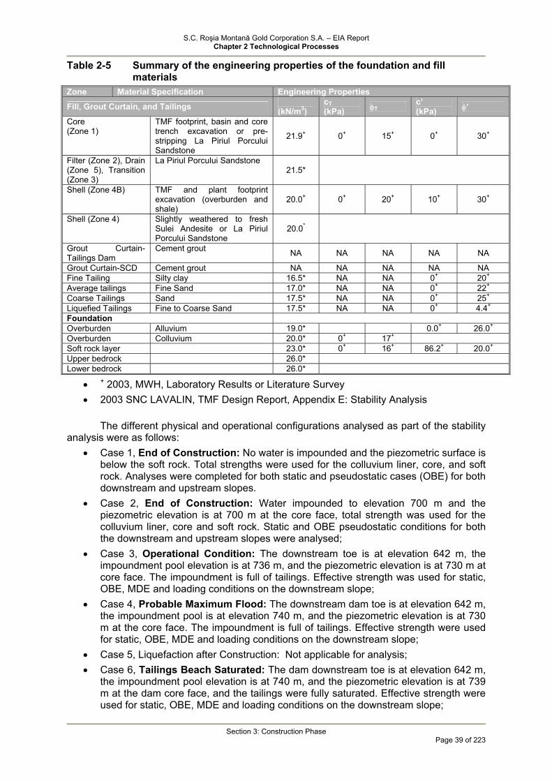
S.C. Roşia Montană Gold Corporation S.A. – EIA Report Chapter 2 Technological Processes
Section 3: Construction Phase
Page 39 of 223
Table 2-5 Summary of the engineering properties of the foundation and fill materials
Zone Material Specification Engineering Properties Fill, Grout Curtain, and Tailings �
(kN/m3) cT (kPa) φT c’
(kPa) φ’
Core (Zone 1)
TMF footprint, basin and core trench excavation or pre-stripping La Piriul Porcului Sandstone
21.9+ 0+ 15+ 0+ 30+
Filter (Zone 2), Drain (Zone 5), Transition (Zone 3)
La Piriul Porcului Sandstone 21.5*
Shell (Zone 4B) TMF and plant footprint excavation (overburden and shale)
20.0+ 0+ 20+ 10+ 30+
Shell (Zone 4) Slightly weathered to fresh Sulei Andesite or La Piriul Porcului Sandstone
20.0*
Grout Curtain-Tailings Dam
Cement grout NA NA NA NA NA
Grout Curtain-SCD Cement grout NA NA NA NA NA Fine Tailing Silty clay 16.5* NA NA 0+ 20+
Average tailings Fine Sand 17.0* NA NA 0+ 22+ Coarse Tailings Sand 17.5* NA NA 0+ 25+ Liquefied Tailings Fine to Coarse Sand 17.5* NA NA 0+ 4.4+ Foundation Overburden Alluvium 19.0* 0.0+ 26.0+
Overburden Colluvium 20.0* 0+ 17+
Soft rock layer 23.0* 0+ 16+ 86.2+ 20.0+
Upper bedrock 26.0*
Lower bedrock 26.0*
• + 2003, MWH, Laboratory Results or Literature Survey • 2003 SNC LAVALIN, TMF Design Report, Appendix E: Stability Analysis
The different physical and operational configurations analysed as part of the stability
analysis were as follows: • Case 1, End of Construction: No water is impounded and the piezometric surface is
below the soft rock. Total strengths were used for the colluvium liner, core, and soft rock. Analyses were completed for both static and pseudostatic cases (OBE) for both downstream and upstream slopes.
• Case 2, End of Construction: Water impounded to elevation 700 m and the piezometric elevation is at 700 m at the core face, total strength was used for the colluvium liner, core and soft rock. Static and OBE pseudostatic conditions for both the downstream and upstream slopes were analysed;
• Case 3, Operational Condition: The downstream toe is at elevation 642 m, the impoundment pool elevation is at 736 m, and the piezometric elevation is at 730 m at core face. The impoundment is full of tailings. Effective strength was used for static, OBE, MDE and loading conditions on the downstream slope;
• Case 4, Probable Maximum Flood: The downstream dam toe is at elevation 642 m, the impoundment pool is at elevation 740 m, and the piezometric elevation is at 730 m at the core face. The impoundment is full of tailings. Effective strength were used for static, OBE, MDE and loading conditions on the downstream slope;
• Case 5, Liquefaction after Construction: Not applicable for analysis; • Case 6, Tailings Beach Saturated: The dam downstream toe is at elevation 642 m,
the impoundment pool elevation is at 740 m, and the piezometric elevation is at 739 m at the dam core face, and the tailings were fully saturated. Effective strength were used for static, OBE, MDE and loading conditions on the downstream slope;
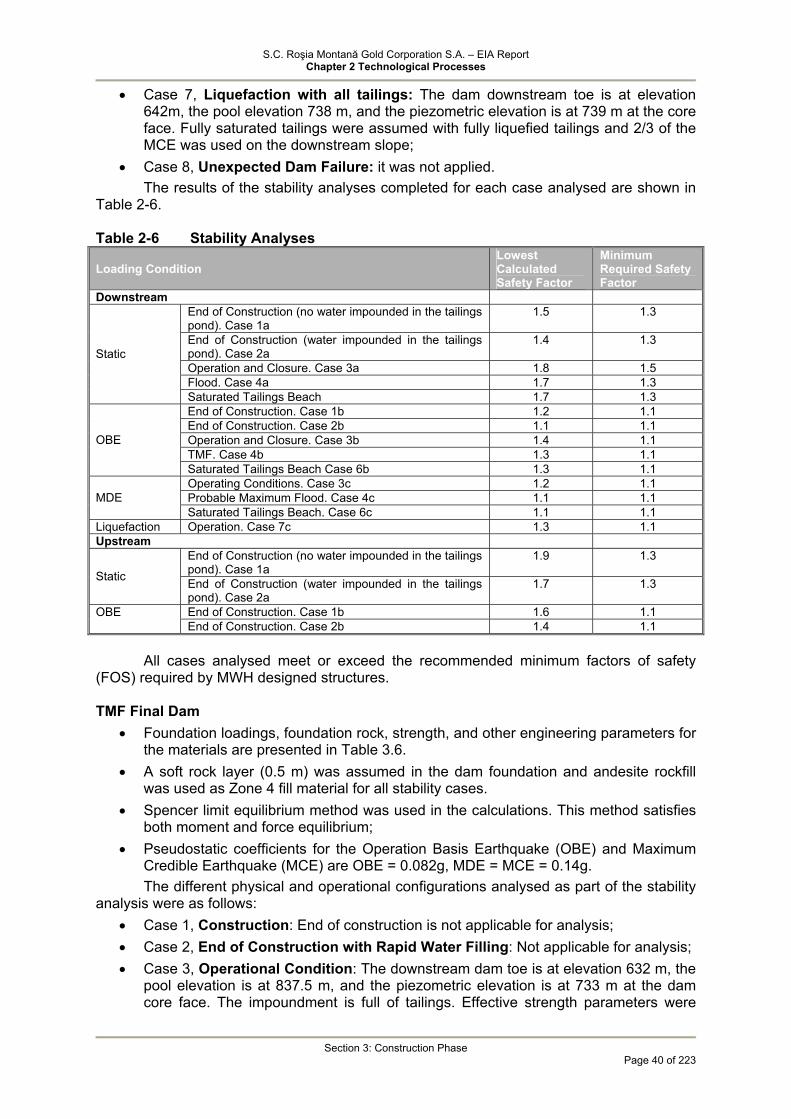
S.C. Roşia Montană Gold Corporation S.A. – EIA Report Chapter 2 Technological Processes
Section 3: Construction Phase
Page 40 of 223
• Case 7, Liquefaction with all tailings: The dam downstream toe is at elevation 642m, the pool elevation 738 m, and the piezometric elevation is at 739 m at the core face. Fully saturated tailings were assumed with fully liquefied tailings and 2/3 of the MCE was used on the downstream slope;
• Case 8, Unexpected Dam Failure: it was not applied. The results of the stability analyses completed for each case analysed are shown in
Table 2-6. Table 2-6 Stability Analyses
Loading Condition Lowest Calculated Safety Factor
Minimum Required Safety Factor
Downstream End of Construction (no water impounded in the tailings pond). Case 1a
1.5 1.3
End of Construction (water impounded in the tailings pond). Case 2a
1.4 1.3
Operation and Closure. Case 3a 1.8 1.5 Flood. Case 4a 1.7 1.3
Static
Saturated Tailings Beach 1.7 1.3 End of Construction. Case 1b 1.2 1.1 End of Construction. Case 2b 1.1 1.1 Operation and Closure. Case 3b 1.4 1.1 TMF. Case 4b 1.3 1.1
OBE
Saturated Tailings Beach Case 6b 1.3 1.1 Operating Conditions. Case 3c 1.2 1.1 Probable Maximum Flood. Case 4c 1.1 1.1 MDE Saturated Tailings Beach. Case 6c 1.1 1.1
Liquefaction Operation. Case 7c 1.3 1.1 Upstream
End of Construction (no water impounded in the tailings pond). Case 1a
1.9 1.3
Static End of Construction (water impounded in the tailings pond). Case 2a
1.7 1.3
End of Construction. Case 1b 1.6 1.1 OBE End of Construction. Case 2b 1.4 1.1
All cases analysed meet or exceed the recommended minimum factors of safety
(FOS) required by MWH designed structures.
TMF Final Dam • Foundation loadings, foundation rock, strength, and other engineering parameters for
the materials are presented in Table 3.6. • A soft rock layer (0.5 m) was assumed in the dam foundation and andesite rockfill
was used as Zone 4 fill material for all stability cases. • Spencer limit equilibrium method was used in the calculations. This method satisfies
both moment and force equilibrium; • Pseudostatic coefficients for the Operation Basis Earthquake (OBE) and Maximum
Credible Earthquake (MCE) are OBE = 0.082g, MDE = MCE = 0.14g. The different physical and operational configurations analysed as part of the stability
analysis were as follows: • Case 1, Construction: End of construction is not applicable for analysis; • Case 2, End of Construction with Rapid Water Filling: Not applicable for analysis; • Case 3, Operational Condition: The downstream dam toe is at elevation 632 m, the
pool elevation is at 837.5 m, and the piezometric elevation is at 733 m at the dam core face. The impoundment is full of tailings. Effective strength parameters were
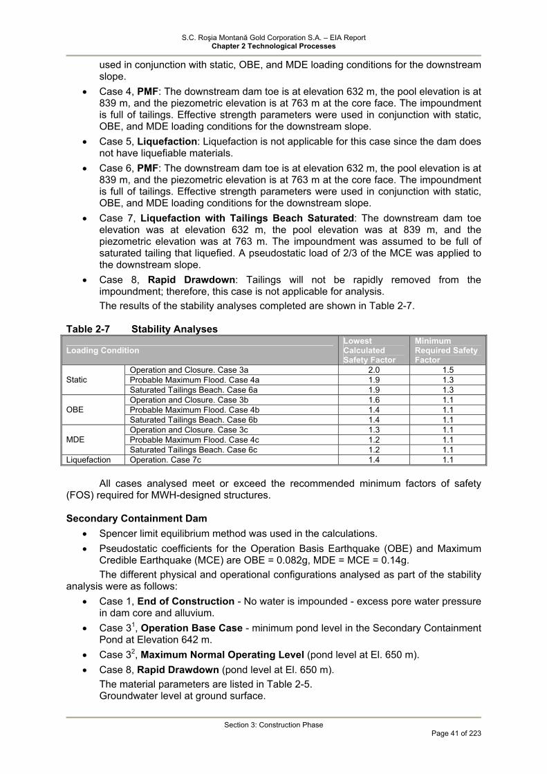
S.C. Roşia Montană Gold Corporation S.A. – EIA Report Chapter 2 Technological Processes
Section 3: Construction Phase
Page 41 of 223
used in conjunction with static, OBE, and MDE loading conditions for the downstream slope.
• Case 4, PMF: The downstream dam toe is at elevation 632 m, the pool elevation is at 839 m, and the piezometric elevation is at 763 m at the core face. The impoundment is full of tailings. Effective strength parameters were used in conjunction with static, OBE, and MDE loading conditions for the downstream slope.
• Case 5, Liquefaction: Liquefaction is not applicable for this case since the dam does not have liquefiable materials.
• Case 6, PMF: The downstream dam toe is at elevation 632 m, the pool elevation is at 839 m, and the piezometric elevation is at 763 m at the core face. The impoundment is full of tailings. Effective strength parameters were used in conjunction with static, OBE, and MDE loading conditions for the downstream slope.
• Case 7, Liquefaction with Tailings Beach Saturated: The downstream dam toe elevation was at elevation 632 m, the pool elevation was at 839 m, and the piezometric elevation was at 763 m. The impoundment was assumed to be full of saturated tailing that liquefied. A pseudostatic load of 2/3 of the MCE was applied to the downstream slope.
• Case 8, Rapid Drawdown: Tailings will not be rapidly removed from the impoundment; therefore, this case is not applicable for analysis. The results of the stability analyses completed are shown in Table 2-7.
Table 2-7 Stability Analyses
Loading Condition Lowest Calculated Safety Factor
Minimum Required Safety Factor
Operation and Closure. Case 3a 2.0 1.5 Probable Maximum Flood. Case 4a 1.9 1.3 Static Saturated Tailings Beach. Case 6a 1.9 1.3 Operation and Closure. Case 3b 1.6 1.1 Probable Maximum Flood. Case 4b 1.4 1.1 OBE Saturated Tailings Beach. Case 6b 1.4 1.1 Operation and Closure. Case 3c 1.3 1.1 Probable Maximum Flood. Case 4c 1.2 1.1 MDE Saturated Tailings Beach. Case 6c 1.2 1.1
Liquefaction Operation. Case 7c 1.4 1.1 All cases analysed meet or exceed the recommended minimum factors of safety
(FOS) required for MWH-designed structures.
Secondary Containment Dam • Spencer limit equilibrium method was used in the calculations. • Pseudostatic coefficients for the Operation Basis Earthquake (OBE) and Maximum
Credible Earthquake (MCE) are OBE = 0.082g, MDE = MCE = 0.14g. The different physical and operational configurations analysed as part of the stability
analysis were as follows: • Case 1, End of Construction - No water is impounded - excess pore water pressure
in dam core and alluvium. • Case 31, Operation Base Case - minimum pond level in the Secondary Containment
Pond at Elevation 642 m. • Case 32, Maximum Normal Operating Level (pond level at El. 650 m). • Case 8, Rapid Drawdown (pond level at El. 650 m).
The material parameters are listed in Table 2-5. Groundwater level at ground surface.
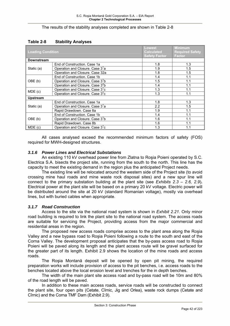
S.C. Roşia Montană Gold Corporation S.A. – EIA Report Chapter 2 Technological Processes
Section 3: Construction Phase
Page 42 of 223
The results of the stability analyses completed are shown in Table 2-8
Table 2-8 Stability Analyses
Loading Condition Lowest Calculated Safety Factor
Minimum Required Safety Factor
Downstream End of Construction. Case 1a 1.8 1.3 Operation and Closure. Case 31a 1.9 1.5 Static (a) Operation and Closure. Case 32a 1.8 1.5 End of Construction. Case 1b 1.4 1.1 Operation and Closure. Case 31b 1.5 1.1 OBE (b) Operation and Closure. Case 32b 1.4 1.1 Operation and Closure. Case 31c 1.3 1.1 MDE (c) Operation and Closure. Case 32c 1.3 1.1
Upstream End of Construction. Case 1a 1.8 1.3 Operation and Closure. Case 31a 2.2 1.5 Static (a) Rapid Drawdown. Case 8a 1.9 1.1 End of Construction. Case 1b 1.4 1.1 Operation and Closure. Case 31b 1.6 1.1 OBE (b) Rapid Drawdown. Case 8b 1.6 1.1
MDE (c) Operation and Closure. Case 31c 1.3 1.1
All cases analysed exceed the recommended minimum factors of safety (FOS) required for MWH-designed structures.
3.1.6 Power Lines and Electrical Substations
An existing 110 kV overhead power line from Zlatna to Roşia Poieni operated by S.C. Electrica S.A. bisects the project site, running from the south to the north. This line has the capacity to meet the existing demand in the region plus the anticipated Project needs.
The existing line will be relocated around the western side of the Project site (to avoid crossing mine haul roads and mine waste rock disposal sites) and a new spur line will connect to the primary substation building at the plant site (see Exhibits 2.3 – 2.6, 2.9). Electrical power at the plant site will be based on a primary 20 kV voltage. Electric power will be distributed around the site at 20 kV (standard Romanian voltage), mostly via overhead lines, but with buried cables when appropriate.
3.1.7 Road Construction
Access to the site via the national road system is shown in Exhibit 2.21. Only minor road building is required to link the plant site to the national road system. The access roads are suitable for servicing the Project, providing access from the major commercial and residential areas in the region.
The proposed new access roads comprise access to the plant area along the Roşia Valley and a new bypass road to Roşia Poieni following a route to the south and east of the Corna Valley. The development proposal anticipates that the by-pass access road to Roşia Poieni will be paved along its length and the plant access route will be gravel surfaced for the greater part of its length. Exhibit 2.9 shows the location of the mine roads and access roads.
The Roşia Montană deposit will be opened by open pit mining, the required preparation works will include provision of access to the pit benches, i.e. access roads to the benches located above the local erosion level and trenches for the in depth benches.
The width of the main plant site access road and by-pass road will be 10m and 80% of the road length will be paved.
In addition to these main access roads, service roads will be constructed to connect the plant site, four open pits (Cetate, Cîrnic, Jig and Orlea), waste rock dumps (Cetate and Cîrnic) and the Corna TMF Dam (Exhibit 2.9).

S.C. Roşia Montană Gold Corporation S.A. – EIA Report Chapter 2 Technological Processes
Section 3: Construction Phase
Page 43 of 223
All main mine material haulage roads will have a minimum width of 30m to ensure safe driving on two traffic lanes of haul trucks. The roads will be covered with gravel and maintained by sprinkling and compacting, in order to increase the productivity of the haul trucks, as well as to reduce the level of airborne particulate.
Vehicle traffic on haul roads will be restricted to light vehicles requiring access to the mine areas in order to carry out activities directly related to the mining operation.
Wherever possible, separate roads for light vehicles will be constructed in order to keep their traffic outside the mine haul roads.
Annual transport capacities required during the Roşia Montană Project life will have to cover the requirement for mine material haulage as follows:
• transport of high grade ore from the open pits to the primary crusher; • first stage transport of low grade ore from the open pits to the low-grade ore stockpile
to be further routed to the primary crusher; • transport of waste rock from the open pits to the waste rock dumps or TMF dam.
The Project road infrastructure will be used by a large variety of vehicles, including: 150 tonne haul trucks (ore and waste rock), trucks (utility purposes); water trucks, motor graders, tracked dozers, hydraulic shovels, loaders, excavators, compactors, front-end loaders, haul trucks/explosive preparation, cranes, buses, pickups, utility vehicles, forklifts, fire trucks.
3.1.8 Construction of the process plant and ancillary facilities
The first construction works conducted onsite, as per the design, will be the planned earthworks. These works may not commence prior to the water supply and construction of access road for equipment and personnel. It is estimated that using 6 scrapers, 6 days/week, 10 hours/day a volume of 2.450.000 m3 can be removed and approximately 480.000 m3 can be filled in 25 weeks.
Table 2-9 lists the major priority sites and the required amount of earthwork. Table 2-9 Earthworks
Name Removed
soil (m3)
Fill (m3)
Priority (m3)
Access road 1
Grinding 694.500 80.200 2
Leaching, reagents etc.
659.300 30.800 3
Low-grade ore stockpile
252.800 39.200 4
Primary crushing - run-of-mine (ROM) ore stockpile
228.600 105.600 5
Gravel granulation 197.400 0 6
Distribution warehouses
200 185.300 7
Stormwater pond 76.100 11.200 8
Vehicle washing station
208.100 900 9
Scale and gate 16.500 19.000 10
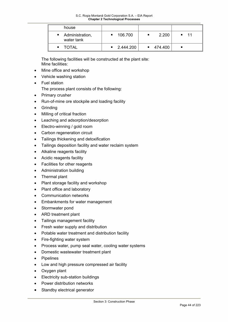
S.C. Roşia Montană Gold Corporation S.A. – EIA Report Chapter 2 Technological Processes
Section 3: Construction Phase
Page 44 of 223
house
Administration, water tank
106.700 2.200 11
TOTAL 2.444.200 474.400
The following facilities will be constructed at the plant site: Mine facilities:
• Mine office and workshop • Vehicle washing station • Fuel station
The process plant consists of the following: • Primary crusher • Run-of-mine ore stockpile and loading facility • Grinding • Milling of critical fraction • Leaching and adsorption/desorption • Electro-winning / gold room • Carbon regeneration circuit • Tailings thickening and detoxification • Tailings deposition facility and water reclaim system • Alkaline reagents facility • Acidic reagents facility • Facilities for other reagents • Administration building • Thermal plant • Plant storage facility and workshop • Plant office and laboratory • Communication networks • Embankments for water management • Stormwater pond • ARD treatment plant • Tailings management facility • Fresh water supply and distribution • Potable water treatment and distribution facility • Fire-fighting water system • Process water, pump seal water, cooling water systems • Domestic wastewater treatment plant • Pipelines • Low and high pressure compressed air facility • Oxygen plant • Electricity sub-station buildings • Power distribution networks • Standby electrical generator
S.C. Roşia Montană Gold Corporation S.A. – EIA Report Chapter 2 Technological Processes
Section 3: Construction Phase
Page 45 of 223
3.1.9 Fresh Water Supply System
The primary supply of fresh water will be a piped supply from the Aries River. The supply infrastructure for the fresh water supply system is proposed as:
• Water intake at the Aries River, upstream of its confluence with the Abrud River; • A pumping station located at the right bank of the Aries River, equipped with pumps
capable of lifting the required flow rate over 420 m elevation difference to a Fresh Water Supply Tank in the vicinity of the processing plant; and,
• A pipeline laid along the Abrud River to Gura Rosiei, and then along the existing mine railway and the new access road to the processing plant, a distance of 13,2 km.
3.1.10 Temporary Hazardous Waste Storage Facility
The Temporary Hazardous Waste Storage will be located outside the process plant site, in the immediate eastern vicinity of the toposoil stockpile excavated from the plant site. It will be a 35x20 m one story construction with height between 5 and 8m, covered with corrugated sheet metal. The facility will be constructed of concrete with concrete floor and drainage gradient, drains and sumps. The facility platform will be waterproofed as follows:
• at the lower side – 150 mm thick layer of clay or recompacted soil; • HDPE liner; • sand drainage layer, 800mm thick; • concrete floor, 150 mm thick;
The storage facility will consist of 3 separate bays constructed using mobile concrete plates, one for storage of waste lead batteries and transformers, and two for storage of sealed hazardous waste drums and containers.
Access to the storage bays will be provided by means of loaders and/or trucks. The Temporary Hazardous Waste Storage site will be fenced and secured.
3.2 Equipment, Material, Utilities, Access Roads, Workforce Requirement
3.2.1 Materials and Equipment It is planned that appropriate regional suppliers and fabricators of structural steel,
suppliers of concrete and reinforcing steel, and suppliers of construction consumables (such as fuel and lube oils) will be employed during the construction phase of the project. Specialised equipment for plant construction will be sourced internationally due to the specialised technology that is required in its design and manufacture. Local resources will be used for in-country transportation and delivery.
A number of support services should be provided during preconstruction and construction including: temporary water supply and distribution, temporary electrical power supply, site preparation, domestic wastewater collection and treatment, construction of temporary buildings, waste management and ancillary services for the constructors.
The large mining equipment requirement estimated for the construction period is the following:
• IR 270 MP Drill rig– 2 items • 19 m3 hydraulic shove – 2 items • CAT 992 Loader – 1 item • CAT 785 C haul truck – 3 items • CAT D9R dozer – 3 items • CAT 834G dozer loader – 2 items • CAT 16H motor grader – 2 items

S.C. Roşia Montană Gold Corporation S.A. – EIA Report Chapter 2 Technological Processes
Section 3: Construction Phase
Page 46 of 223
• CAT 777D water truck – 2 items • CAT 988 Loader – 1 item • CAT 773D haul truck – 1 item • IR ECM 590 rock drill – 1 item • 325 BL Excavator – 1 item
A 250 t mobile crane, other cranes and equipment are provided by each indvidual contractor.
Table 2-10 lists the material quantities estimated for the most important constructions within the process plant site.

S.C. Roşia Montană Gold Corporation S.A. – EIA Report Chapter 2 Technological Processes
Section 3: Construction Phase
Page 47 of 223
Table 2-10 Estimated material quantities
No. Material Category MU Primary Crushing Facility
Crushed Ore Stockpile
Critical Fraction Crushing Facility
Grinding Section
Cyanidation, Stripping, Electrowinning and Smelting Facility
Reagent Facility
Utilities, Tailings Distribution System, Other Industrial Structures
1 Reinforced concrete m3 2478 4764 344 10426 8851 1847 2744 2 Simple concrete m3 34 38 10 170 293 52 870 3 Metal structures t 428 206 443 4790,5 824 1275 84 4 Masonry m3/m2 36/213 - 21,5/107 1541/2392 - 97/613 45 5 Doors/windows items 11/2 - 6/0 66 9 15 29 6 Plaster m2 390 - 160 5431 641 1113 1332 7 Air conditioning and ventilation
systems items - - - 10 - 10 -
8 Metallic pipes from ø 700 to ø 20mm m - - - 3388 - 3138 35429 9 Plastic pipes from ø 800 la ø 50 m - - - 2677 - - -

S.C. Roşia Montană Gold Corporation S.A. – EIA Report Chapter 2 Technological Processes
Section 3: Construction Phase
Page 48 of 223
3.2.2 Facilities – Temporary Constructions: A number of temporary buildings will be constructed to support construction:
• construction management offices, warehouse, maintenance shop, material laboratory, medical-aid clinic, field washrooms, TMF field office, quarry field office, temporary guardhouse,
• Garduri de securitate, împrejmuiri temporare ale generatoarelor, linii telefonice.Security fencing, temporary enclosure for generators, telephones.
• Staţie de carburanţi, generatorul temporar şi camera de comandăFuel station, backup power generator and control room
• Fenced areas for storage of construction materials: this area is designed for manufacturing and storage of steel structures and will be temporarily located in the northern part of the process plant site. Additional temporary laydown areas will be located inside the process plant, as necessary, to support particular phases of construction. Laydown areas will include modular buildings or weatherproof containers for the storage of tools, welding consumables, compressed gases, paint, and other materials. Covered storage will be provided for insulation, electric motors and machinery, wood, and other materials or equipment requiring a measure of protection from precipitation prior to installation. Open storage areas will be used for steel beams, piping, sheathing and roofing materials, and other materials not requiring protection from precipitation; Receiving and warehousing requirements will be significant due to the volume of materials that will be required for completion of construction. Warehouse management will require a dedicated workforce of personnel, drawn in part, from the local populace for proper organization in support of the construction activities.
• Batch Concrete Production Plant: This will be installed in the vicinity of the process plant construction area. Aggregate for the batch process will be provided from onsite quarries. A small stockpile will be maintained at the batch plant site. The concrete batch plant will be operated with a concrete production capacity of approximately 40 m3/h and will consist of: aggregate dragline, aggregate and cement storage, weightbatcher, cement conveyer, concrete mixing machine and bunker. Power will be provided by a portable diesel generator until completion of the relocation of the main transmission line and plant substation, at which time a temporary distribution line and transformer will be provided to service the batch plant. The batch plant will be decommissioned and removed from the site at the completion of the construction phase of the project.
3.2.3 Utility services - temporary facilities 3.2.3.1 Temporary Water Supply and Distribution:
Water will be provided for potable and industrial use at the plant site and construction camp. Water for fire protection will also be provided;
During this interim period, the potable water needs onsite and for construction is estimated at maximum 600.000 l/day. In order to cover this demand, the existing water supply to Gura Rosiei will be used to the extent possible and will be completed with water supplied by tank car from Cîmpeni. The water will be stored in a steel frost-safe buffer tank. From the tank the water will be treated through the treatment plant.
Water consumption for domestic use and laundering is estimated at 300,000 l/day. Industrial and fire water will be stored in insulated tanks. This estimate does not include the water for the concrete and aggregate plant. The water distribution systems will be buried and isolated against frost and will be
equipped with hydrants and distribution networks in the buildings. 3.2.3.2 Temporary Power:
Electrical power will be supplied by mobile generators located at the plant site. The generators will be used until a permanent electrical power supply is available. During

S.C. Roşia Montană Gold Corporation S.A. – EIA Report Chapter 2 Technological Processes
Section 3: Construction Phase
Page 49 of 223
development of on-site quarries, RMGC will provide temporary power to the quarry office/trailer.
Standard generators between 250 – 500 kVA each provided with distribution network and earth circuit. They are located according to necessities. The generators will be installed at the primary crusher, grinding, CIL tanks, reagent preparation/water tanks, gold room/desorption etc.
3.2.4 Access Roads
Several roads must be provided to facilitate Roşia construction activities. During the initial construction phase the road access to the plant site will be constructed on the south side of the Roşia Valley, starting from the existing road in the Roşia Montană Valley as shown on Exhibit 2.9. This road will subsequently become a secondary plant access road for authorized mine personnel use only.
A number of other existing roads require upgrading for use during the construction period. Over 1 km of access roads must be constructed from existing roads to provide access to the sandstone and andesite quarries. The roads should also be operational during winter months.
3.2.5 Workforce
The RMGC Human Resources Department will implement hiring policies with preference being given to local persons in cases where their attributes are equal. During the construction and operational life of the Project, when special skills are unavailable locally and training is not practicable due to time constraints, suitably qualified personnel will be hired from outside the local area. Moreover, the local labour force will be a prime source of labour for Romanian and international contractors contracted by RMGC to supply the craft disciplines for the construction of the Project.
The onsite workforce during construction varies from 800 to 1200 people, of which 80% male and 20% female.
3.3 Pollution Sources
3.3.1 Emissions 3.3.1.1 Atmospheric emissions Generated by mining activities:
Pollution Sources: • suspended particulate matter generated by preparatory works, drilling/blasting,
loading, transport, unloading, grading, uncontrolled mobile sources; • combustion gases : from the internal combustion engines of drilling, loading, haulage,
grading machines - uncontrolled mobile sources; All activities carried out during construction for preparation of the proposed site (open
pits and stockpiles) are fugitive dust emission sources as well as specific sources of exhaust gas, noise and vibration:
• Fugitive dust emissions generated by excavation, loading into haul trucks, stockpiling and truck haulage on service roads; Pollutants from exhaust gas including NO, NO2, N2O, CO, CO2, SO2, CH4; VOCnm,
volatile organic compounds and heavy metal particles: Cd, Cu, Cr, Ni, Se, Zi. Tables 4.2.7; 4.2.8 and 4.2.9 include an emission inventory for the construction
phase and Tables 4.2.10 şi 4.2.11 in Section 4.2 AIR list the provenance of emission sources. The calculated concentrations in the construction phase are described in Section AIR. Emissions generated by stationary sources within the plant site are associated to the following:

S.C. Roşia Montană Gold Corporation S.A. – EIA Report Chapter 2 Technological Processes
Section 3: Construction Phase
Page 50 of 223
• Cement and concrete batch plant constituting stationary and mobile emission sources of air pollutants. Activities generating emissions include: handling (supply, storage and transfer) of raw materials (aggregates, sand, cement and lime), raw material processing and concrete or cement transport to the placement site. Preparation of concrete includes storage of raw materials (cement, lime, aggregates, additives), transportation of materials to silos and mixing machines, cement/concrete processing, loading of products into agitating trucks for transportation to the construction site. The handling, storage and potential erosion of aggregate stockpiles will generate emissions.
• Transport and handling of construction materials and components by vehicles and other equipment with internal combustion engines. The following pollutants will be released as a result of fuel consumption: NOx, SOx, CO, CO2, COV, NO2, traces of metallic particulates (Cd, Cu, Ni, Se, Zn) and PAH. (polynomial aromatic hydrocarbons). Minor emission sources at the construction site will be generated by the cutting and
welding of steel structures, painting of buildings and other structures. Emissions related to construction activities from controlled stationary sources are
listed in Table 4.2.8 - Section 4.2. AIR, emissions from mobile sources are summarised in Table 4.2.9 and source parameters in Table 4.2.10.
The following will be provided for the mitigation of toxic emissions during the construction phase:
• Watering of open areas used for handling of dust-generating material; • Control of emission from the road surface in dry season by using movable sprinkling
systems or water trucks and inert chemical substances; • Use of mobile or stationary ventilation systems and respiratory protection devices; • Use of mobile systems for dust gathering from dust-generating locations; • Standard operating procedures regarding cessation of dust-generating activities
under strong wind conditions; • Standard operating procedures regarding minimisation of gas emissions from fuel
operations; • Reduction of loading/unloading height of dust-generating materials.
Machinery and equipment should strictly comply with the EU and/or Romanian standard emission levels for mobile and stationary equipment. A maintenance and repairs program will be implemented for mobile and stationary equipment in order to ensure compliance with the regulatory requirements.
3.3.1.2 Sources of Emissions to Water
There are no additional water pollution sources during the construction phase. Current water pollution sources originate from existing ore and tailings deposits resulting from previous mining operations.
The following pollution sources may occur within the plant site during construction: Sediment transport from the site due to large storm events and subsequent
deposition in water bodies. Sediment loads in water bodies will be the result of by the of the mine working
characteristics and likely degradation of the initial conditions and access routes. Small collection ponds and retention structures will be constructed to control and
mitigate sediment runoff. These operations are described in detail in the Water Management and Erosion Control Plan (ESMS Plans, Plan C).
Temporary discharge of sewage in the Roşia River: Sewage collection and treatment will be provided during the early construction
phases of the Project to meet regulatory discharge requirements. In addition, portable toilet facilities will be located in outlying field areas. Sewage water will be treated to meet Romanian water quality standards. In addition, part of domestic sewage discharges from

S.C. Roşia Montană Gold Corporation S.A. – EIA Report Chapter 2 Technological Processes
Section 3: Construction Phase
Page 51 of 223
showers and washing machines will be collected and transported offsite and discharged to the existing municipal treatment plants.
3.3.1.3 Pollutant Emissions on SOIL/SUBSOIL
Soil and subsoil pollution sources are specific to preparatory mine works conducted in the construction phase in correlation with the employed mining method, as follows:
• occupation of land areas for preparation of the new sites (open pits); • occupation of land areas used for the waste rock dumps; • occupation of land areas used for access and connecting roads; • accidental spillage of petroleum products which may occur due to leakage of the fuel
tanks or repairs of equipment in unsuitable locations. Current soil pollution sources during construction within the project boundary
originate from the existing rock stockpiles and processing of ore from previous mining operations.
An area of some 1061,61 ha of land will be affected by the development of the Project with impact on soil and subsoil resources.
During construction topsoil and subsoil resources within selected areas will be stripped and stockpiled for use in the rehabilitation of the area during progressive and final closure.
The following soil pollution sources may occur within the plant site during construction:
• Dust generated by handling (loading, transportation and storage/stockpiling) of soil excavations on the site.
• Dust and exhaust gases generated by the operation and movement of vehicles on the roads. As dust is generated, particles will be deposited in unprotected areas.
• Dust generated by concrete batch plants located within the plant site • Areas of repairing activities and oil change for vehicles and equipment • Storage sites of oils, fuel and other petroleum products • Waste and hazardous and non-hazardous material accumulation and storage areas
until they are removed from the site. No chemicals will be used during construction. The following measures will applied to mitigate pollutant emissions affecting the
environmental media SOIL. • Storage areas for fuels, lubricants and fuel station area will be constructed near
maintenance shops. • Leaks and/or spills within the fuel station area will be retained in mobile recipients
provided with safety guards or self-closing valves. • Use of mobile systems for dust gathering from dust-generating locations; • Watering of roadways and pulverous material storage sites. • Asbestos-bearing materials will not be permitted for the construction of the process
plant or ancillary facilities.
3.3.2 Noise and Vibration Noise and vibration sources during construction are as follows:
• Local and access roads (background noise); • Operation of haul trucks of materials resulting from preparation activities; • Operation of trucks and heavy equipment for preparation of new sites (open pits and
waste rock dumps); • Operation of mobile electrical generators;
S.C. Roşia Montană Gold Corporation S.A. – EIA Report Chapter 2 Technological Processes
Section 3: Construction Phase
Page 52 of 223
• Use of heavy vehicle alarm systems; • sirens, horns etc.
o Noise sources during construction are as follows: • Operation of heavy equipment and other noise-generating machines used for demolition
of existing structures within the Project’s industrial protection zone boundary; • Operation of trucks and other heavy equipment for the transport and placement of
temporary dwellings, offices and other structures within the construction zone boundary and their subsequent demolition/decommissioning;
• Construction of processing facilities, storage buildings and warehouses and other ancillary constructions (e.g. explosives storage facility, temporary hazardous waste storage facility);
• Operation of trucks and heavy equipment for: • temporary construction/demolition of the concrete batch plant; • road construction and maintenance; • surface water diversion works and earthworks; • Operation of mobile electrical generators;
The noise and vibration mitigation measures will be BAT as specified in Table 4.3.5, Section 4.3 Noise and Vibrations.
The measures proposed to reduce the noise and vibration impacts associated with the Project consist of a combination of the following measures:
Engineering Measures: Engineering measures: sound insulation for the buildings at the process plant site etc.;
Institutional control implementation by establishment of protection zones, installation and imposing of speed limits for vehicles, suitable safety equipment for employees as per the health and safety program defined by the RMGC Occupational Health and Safety Plan.
Implementation of adequate control techniques and procedures such as maintenance and repairing schedule for the major equipment and machinery to ensure that sound emissions comply with the normal operational limits;
Management Controls, active engagement of the public and other external factors in the identification and resolution of noise and vibration issues through the communication mechanisms defined in the Public Consultation and Disclosure Plan (ESMS Plans, Plan K) and the procedures for corrective and preventive actions described in the Roşia Montană Project Environmental and Social Management Plan (ESMS Plans, Plan A).
Noise management, mitigation policies and specific measures to be applied during construction are described in Sections 4.3.7.1, 4.3.7.2 and 4.3.7.3.
3.4 Waste
The following categories of waste will be generated during the closure of mining and ore processing activities and connected activities within the Roşia Montană Project:
• municipal and similar waste; • non-hazardous (biodegradable, packaging waste); • slurry from the wastewater treatment plant; • non-inert demolition waste; • production waste; • hazardous production waste (paint residue, spent solvents, oils, lubricants etc.) • non-hazardous production waste; • waste generated by medical activities.

S.C. Roşia Montană Gold Corporation S.A. – EIA Report Chapter 2 Technological Processes
Section 3: Construction Phase
Page 53 of 223
NOTE: Asbestos or asbestos-bearing materials will not be used during construction. The amount of wastes generated during each Project Phase as well as measures
applied to minimise the generation of additional amount of wastes are described in detail in Section 3 “Waste”.
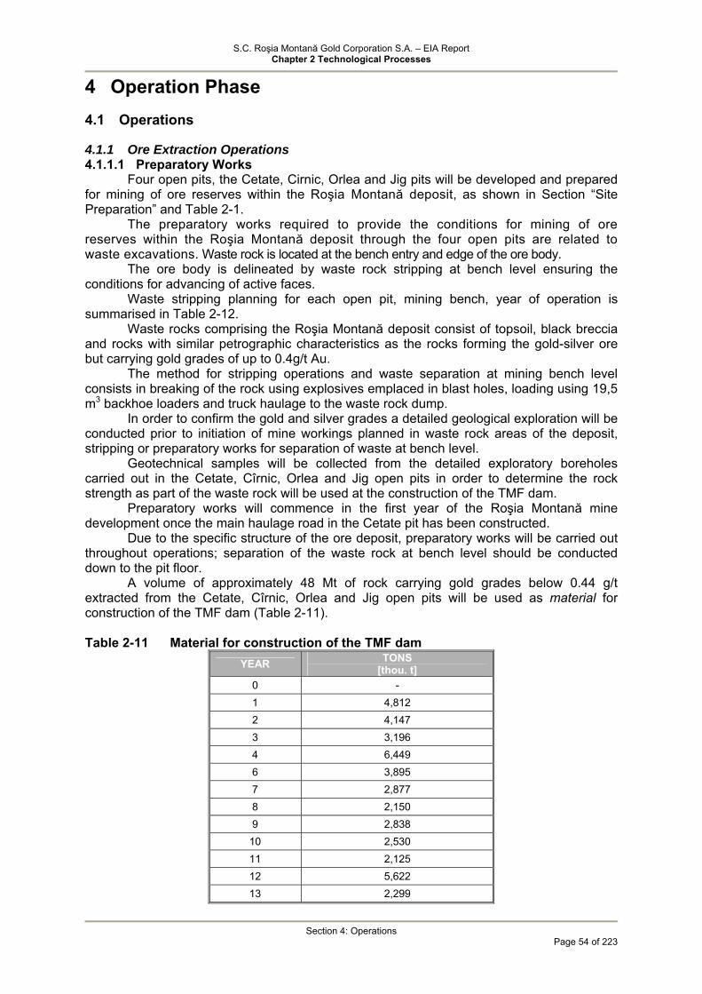
S.C. Roşia Montană Gold Corporation S.A. – EIA Report Chapter 2 Technological Processes
Section 4: Operations
Page 54 of 223
4 Operation Phase 4.1 Operations
4.1.1 Ore Extraction Operations 4.1.1.1 Preparatory Works
Four open pits, the Cetate, Cirnic, Orlea and Jig pits will be developed and prepared for mining of ore reserves within the Roşia Montană deposit, as shown in Section “Site Preparation” and Table 2-1.
The preparatory works required to provide the conditions for mining of ore reserves within the Roşia Montană deposit through the four open pits are related to waste excavations. Waste rock is located at the bench entry and edge of the ore body.
The ore body is delineated by waste rock stripping at bench level ensuring the conditions for advancing of active faces.
Waste stripping planning for each open pit, mining bench, year of operation is summarised in Table 2-12.
Waste rocks comprising the Roşia Montană deposit consist of topsoil, black breccia and rocks with similar petrographic characteristics as the rocks forming the gold-silver ore but carrying gold grades of up to 0.4g/t Au.
The method for stripping operations and waste separation at mining bench level consists in breaking of the rock using explosives emplaced in blast holes, loading using 19,5 m3 backhoe loaders and truck haulage to the waste rock dump.
In order to confirm the gold and silver grades a detailed geological exploration will be conducted prior to initiation of mine workings planned in waste rock areas of the deposit, stripping or preparatory works for separation of waste at bench level.
Geotechnical samples will be collected from the detailed exploratory boreholes carried out in the Cetate, Cîrnic, Orlea and Jig open pits in order to determine the rock strength as part of the waste rock will be used at the construction of the TMF dam.
Preparatory works will commence in the first year of the Roşia Montană mine development once the main haulage road in the Cetate pit has been constructed.
Due to the specific structure of the ore deposit, preparatory works will be carried out throughout operations; separation of the waste rock at bench level should be conducted down to the pit floor.
A volume of approximately 48 Mt of rock carrying gold grades below 0.44 g/t extracted from the Cetate, Cîrnic, Orlea and Jig open pits will be used as material for construction of the TMF dam (Table 2-11). Table 2-11 Material for construction of the TMF dam
YEAR TONS [thou. t]
0 - 1 4,812 2 4,147 3 3,196 4 6,449 6 3,895 7 2,877 8 2,150 9 2,838
10 2,530 11 2,125 12 5,622 13 2,299

S.C. Roşia Montană Gold Corporation S.A. – EIA Report Chapter 2 Technological Processes
Section 4: Operations
Page 55 of 223
14 4,885 Total 47,825
In order to achieve the material requirement for the construction of the TMF dam,
RMGC will develop an aggregate quarry located in the Roşia Montană mining-development area, namely the Sulei quarry.
According to the final mining model of the Roşia Montană open pits, the total volume of excavated waste is 106,167 mil. m3 (256,926 mil. t), as follows: Table 2-12 Sequencing of waste excavations
Open Pit Year Cetate
[Mt] Cârnic
[Mt] Orlea [Mt]
Jig [Mt]
Total [Mt]
0 - 343 - - 343
1 7,922 8,930 - - 16,852
2 4,402 10,523 - - 14,825
3 16,093 3,336 - - 19,429
4 8,569 11,490 - - 20,059
5 - 18,685 - - 18,685
6 - 20,947 - - 20,947
7 - 21,358 393 - 21,751
8 - 15,569 6,441 - 22,010
9 4,134 3,797 11,610 1,578 21,119
10 8,797 - 5,256 3,534 17,587
11 11,120 - 1,558 5,005 17,683
12 18,954 - 934 - 19,888
13 19,024 - - - 19,024
14 6,624 - - 6,624
TOTAL 105,639 (43,652 mil. m3)
114,978 (47,512 mil. m3)
26,192 (10,823 mil
m3)
10,117 (4,180 mil.
m3)
256,926 (106,167 mil
m3) 4.1.1.2 Mining Works
Both geological and morphological conditions and equipment to be acquired through the investment project have been considered in the choice of the method used for open pit mining;
The following have been considered: geological – technical characteristics of the deposit; predominant vertical distribution of the mineable mineral resources over a relatively
extended area; in order to ensure economic efficiency given the relatively low average grades of the
gold-silver mineralisation, a large production capacity must be achieved by employing cost-effective and highly effective mining methods;
provision of mining equipment according to the investment plan consisting of highly effective machines, specific to open pit mining (excavators, bulldozers, haul trucks, loaders, drill rigs etc.);
availability in the Roşia Montană area of technical personnel specialised in mining (mine engineers, mine supervisors, mine igniter, miners etc.). The Roşia Montană deposit is interpreted to be a maar-diatreme complex formed by
the intrusion of sub-volcanic bodies in a sequence of cretaceous sedimentary rocks.
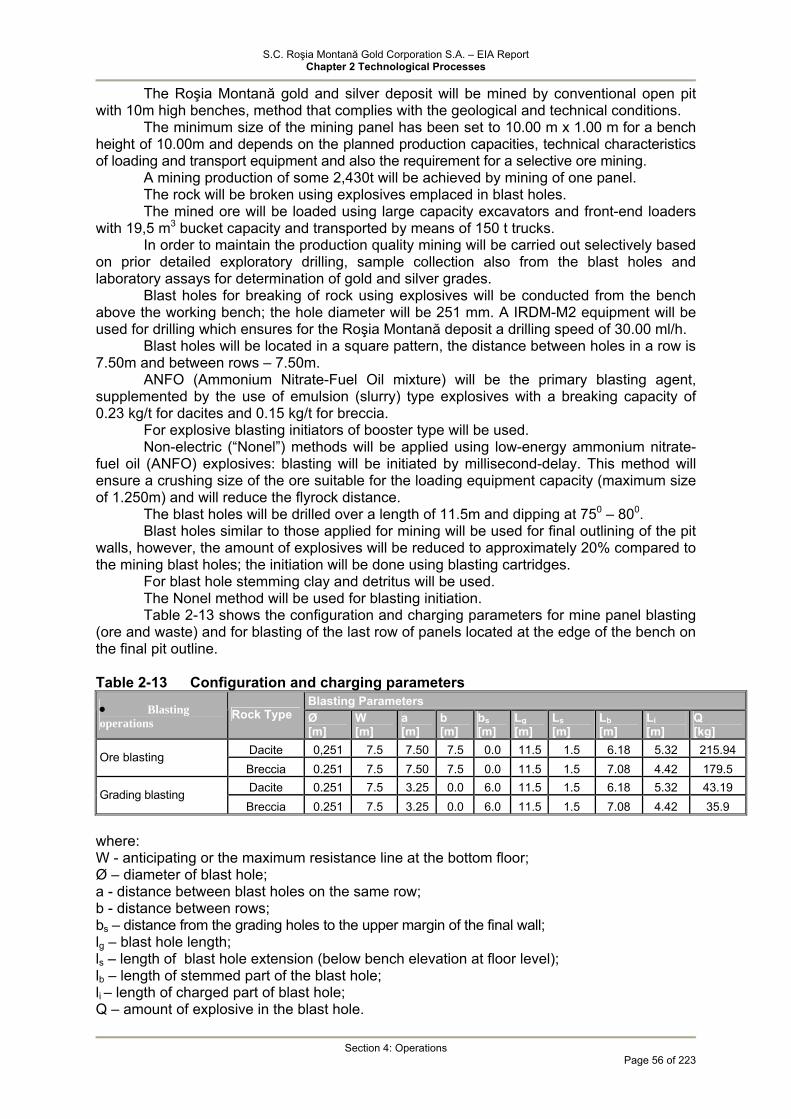
S.C. Roşia Montană Gold Corporation S.A. – EIA Report Chapter 2 Technological Processes
Section 4: Operations
Page 56 of 223
The Roşia Montană gold and silver deposit will be mined by conventional open pit with 10m high benches, method that complies with the geological and technical conditions.
The minimum size of the mining panel has been set to 10.00 m x 1.00 m for a bench height of 10.00m and depends on the planned production capacities, technical characteristics of loading and transport equipment and also the requirement for a selective ore mining.
A mining production of some 2,430t will be achieved by mining of one panel. The rock will be broken using explosives emplaced in blast holes. The mined ore will be loaded using large capacity excavators and front-end loaders
with 19,5 m3 bucket capacity and transported by means of 150 t trucks. In order to maintain the production quality mining will be carried out selectively based
on prior detailed exploratory drilling, sample collection also from the blast holes and laboratory assays for determination of gold and silver grades.
Blast holes for breaking of rock using explosives will be conducted from the bench above the working bench; the hole diameter will be 251 mm. A IRDM-M2 equipment will be used for drilling which ensures for the Roşia Montană deposit a drilling speed of 30.00 ml/h.
Blast holes will be located in a square pattern, the distance between holes in a row is 7.50m and between rows – 7.50m.
ANFO (Ammonium Nitrate-Fuel Oil mixture) will be the primary blasting agent, supplemented by the use of emulsion (slurry) type explosives with a breaking capacity of 0.23 kg/t for dacites and 0.15 kg/t for breccia.
For explosive blasting initiators of booster type will be used. Non-electric (“Nonel”) methods will be applied using low-energy ammonium nitrate-
fuel oil (ANFO) explosives: blasting will be initiated by millisecond-delay. This method will ensure a crushing size of the ore suitable for the loading equipment capacity (maximum size of 1.250m) and will reduce the flyrock distance.
The blast holes will be drilled over a length of 11.5m and dipping at 750 – 800. Blast holes similar to those applied for mining will be used for final outlining of the pit
walls, however, the amount of explosives will be reduced to approximately 20% compared to the mining blast holes; the initiation will be done using blasting cartridges.
For blast hole stemming clay and detritus will be used. The Nonel method will be used for blasting initiation. Table 2-13 shows the configuration and charging parameters for mine panel blasting
(ore and waste) and for blasting of the last row of panels located at the edge of the bench on the final pit outline. Table 2-13 Configuration and charging parameters
Blasting Parameters • Blasting operations Rock Type Ø
[m] W [m]
a [m]
b [m]
bs [m]
Lg [m]
Ls [m]
Lb [m]
Li [m]
Q [kg]
Dacite 0,251 7.5 7.50 7.5 0.0 11.5 1.5 6.18 5.32 215.94 Ore blasting Breccia 0.251 7.5 7.50 7.5 0.0 11.5 1.5 7.08 4.42 179.5 Dacite 0.251 7.5 3.25 0.0 6.0 11.5 1.5 6.18 5.32 43.19 Grading blasting Breccia 0.251 7.5 3.25 0.0 6.0 11.5 1.5 7.08 4.42 35.9
where: W - anticipating or the maximum resistance line at the bottom floor; Ø – diameter of blast hole; a - distance between blast holes on the same row; b - distance between rows; bs – distance from the grading holes to the upper margin of the final wall; lg – blast hole length; ls – length of blast hole extension (below bench elevation at floor level); lb – length of stemmed part of the blast hole; li – length of charged part of blast hole; Q – amount of explosive in the blast hole.
S.C. Roşia Montană Gold Corporation S.A. – EIA Report Chapter 2 Technological Processes
Section 4: Operations
Page 57 of 223
The blast sequence will take place with millisecond delay from the centre of the hole to the bottom and upward and from the central hole of the first row towards the side margins and subsequent rows, this technology ensures a significant reduction of the seismic wave and increased efficiency of blasting.
In a blasting session up to 1296 kg AM will be detonated, resulting a volume of ore of 8,000 – 10,000 t. Blasting of approximately 28-32 mining panels is required and detonation of approximately 10 t of AM explosives.
After blasting, the broken ore will be removed from the bench level, loaded into trucks using excavators and hauled to the process plant or waste rock dump.
A total of 4 main areas were identified based on the spatial distribution of the gold and silver resources where opportunity exists for the development of large scale open pits i.e. Cetate (Cetate and Carpeni), Cîrnic (Cîrnic and Cîrnicel), Orlea and Jig.
The open pits will develop on both sides of the Roşia Valley at depths ranging between 220 m/170 m and 260 m/420 m.
The Cetate pit is located in the south-western part of an area where gold and silver resources were delineated at a distance of 600 m of the process plant site. The estimated resources from the Cetate and Carpeni areas will be mined in the Cetate pit.
The Cetate pit is oval in shape, it has two floors, one in the northern part of the pit at El. +680m and the other in the southern part at El. +650m.
southern part, comprising the Cetate Massif, developed in 24 benches between El. + 920 m and El. + 680 m.
northern part, comprising the side of the massif up to the Roşia Valley boundary, developed over 18 benches between El. + 920 m and El. + 740 m. The final shape of the pit is elliptical with a length of 1200m along the north-south
centerline and width of 700m along the east-west centerline. Resources from Cîrnic, Cîrnicel and part of Cetate areas will be mined in the Cîrnic
pit. The pit is located in the Cîrnic Massif, east of the Cetate pit, the removal of a mountainside located in the eastern part of the pit with highest elevation at 1080m being required to mine this pit.
The pit is developed on the left slope of the Roşia valley, the ultimate pit floor will be located at El. + 600 in the north and + 810m in the south.
• northern part will have 42 benches between El. + 1080 m and El. + 660 m; • southern part will have 17 benches between El. + 980 m and El. + 810 m.
Upon completion of mining works, the final shape of the pit will be almost circular extending E-W over 900m and N-S over 1100m.
The Orlea and Jig pits are located in the northern part of the area, on the other slope of the Roşia valley, the ore mined from these pits will be transported by a main haulage road east of the Cetate pit in case of Orlea pit and by the road located north of the Cetate and Cîrnic in case of Jig pit.
The Orlea pit will be located in the north-western part of the Cetate and Cîrnic pits on the eastern slope of the Roşia valley.
The Orlea pit is opened on the left slope of Roşia valley south of the Orlea Massif; mining works will comprise the removal of the upper part of the mountainside over the 870 m – 750 m interval, the final pit will have two floors, one in the east and one in the west, both at the same elevation, i.e. 600m:
• western part, 21 benches between El. + 870 m and El. + 660 m; • eastern part, 20 benches between El. + 860 m and El. + 660 m;
The Orlea pit will be oval in shape and will extend 1020m E-W and 460m N-S. The Jig pit involves stripping of the hillside starting at El. 900 m. The Jig pit is developed on the right side of the Roşia valley, east of the Orlea pit and
in the southern slope of the Jig Massif and it is the smallest pit in terms of plane extension and depth. The final pit will have two floors located along a NV-SE alignment; final elevations will be 820 m and 850 m, respectively.

S.C. Roşia Montană Gold Corporation S.A. – EIA Report Chapter 2 Technological Processes
Section 4: Operations
Page 58 of 223
• western part, 17 benches between El. + 980 m and El. + 820 m; • central part, 15 benches between El. + 1020 m and El. + 850 m; • eastern part, 13 benches between El. + 1000 m and El. + 870 m.
Mining units within the pits are the pit benches designed with a height of 10m. The benches are located in combined ore and waste zones, subject to the spatial distribution of the resources. Benches in ore will develop within the designed footprints both above and under the terrain topography.
The following volumes of ore will be mined and processed during the 16 years period under review (Table 2-14): Table 2-14 Volumes of excavated ore
Metal Open Pit Ore
[thou. tone] Au [kg]
Ag [kg]
Waste [thou. t]
Cetate 57,292 64,228 187,924 105,639 Cîrnic 112,376 135,516 645,045 114,978 Orlea 39,829 41,429 51,787 26,192 Jig 5,408 5,878 14,214 10,117 Total 214,905 247,051 898,970 256,926
The overall sequence of operations is shown on Exhibits 2.3 - 2.6. They indicate the
site area at the end of years 0, 7, 14 and 16.
4.1.1.3 Waste Rock Stockpiling Waste Rock and Low-grade Ore Stockpiles
Waste rocks that will not be used for the TMF dam construction will be stockpiled on two sites outside the pit perimeters.
The Cetate waste rock dump will cover an estimated surface area of approximately 38,2 ha and will contain approximately 9 million m3 of waste rock material.
The proposed Cîrnic waste rock disposal site will have an approximate surface area of 139.16 ha and contain approximately 50 million m3 of waste rock material. The Cîrnic pit will be backfilled with some 17 million m3 of waste rock.
The Jig pit will be backfilled with some 5 million m3 of waste rock, the Orlea pit will be partially backfilled with some 9 million m3, and the Cetate pit will be flooded. The final design for backfilling of open pits and aggregate quarries is currently under development.
The low-grade ore stockpile will be located east of the Cetate waste rock dump and will contain approximately 13 million m3 of low-grade ore.
Table 2-15 summarises the waste rock distribution by open pit and stockpiling location. Table 2-15 Waste rock distribution by open pit and stockpiling location
Waste Rock Dumps
OPEN PIT WASTE (mil m3)
Cetate Dump (Mm3)
Umplutură cariera Cetate (Mm3)
Halda Cîrnic (Mm3)
Umplutură carieră Cîrnic (Mm3)
Umplutură carieră Orlea (Mm3)
Umplutură carieră Jig (Mm3)
Cîrnic 47,512 - - - - Cetate 43,652 8.797 8,437 4,934 Orlea 10,823 - - - Jig 4,180 - 0.0045 - - -
Total 106,167 8.797 0.0046 45,203 19,030 8,437 4,935
The balance of some 19.76 million m3 and some 47,825 mil. t, respectively of excavated waste material which will not be stored in the waste dumps will be used for the TMF dam construction and successive raises.
S.C. Roşia Montană Gold Corporation S.A. – EIA Report Chapter 2 Technological Processes
Section 4: Operations
Page 59 of 223
The waste rock dumps were designed with 20m high benches, 15m wide safety berms and 27° batter angles, giving an overall waste dump face angle of approximately 22°.
The Cetate dump is located west of the Cetate pit and north of the process plant, on an area where detailed geological exploration has not delineated any mineral resources. An ARD water catchment system will be located downstream of the waste rock dump to provide acidic runoff drainage and routing to the treatment plant.
The Cîrnic waste rock dump is located south-east of the Cîrnic pit, upstream of the tailings deposition pond, on the hillsides and in the Corna Valley. ARD water drained from the Cîrnic waste rock area will be collected and routed to the ARD treatment plant.
The lithological structure of the rocks within the Cetate dump site and Cîrnic dump includes topsoil up to 0.4 m deep, bedrock consisting of shale, dacite and breccia; the upper bedrock is strongly fissured and weathered over some 3.0 – 6.0 m.
In the Cetate and Cîrnic waste dump sites the detailed geological exploration has not delineated any mineral resources.
Stockpiling will be carried out on the pad at El. +850 m in the southern part of the pit, while maintaining the main access to the pit at El. +900 m.
Starting with Year 9 of operations, once the mining of the Cîrnic pit is completed, the waste rock generated by mining of the Orlea and Jig open pits will be stockpiled in the Cîrnic pit.
Stockpiling will start at the pit floor in the north-western part near the access road at +690 m bench level.
The inner Cîrnic waste dump will have an ultimate height of 160m at the end of Year 16 when the dump is closed and environmental reconstruction commences.
The waste rock dumps will be constructed progressively as the pit mining works develop.
4.1.1.4 Mine Dewatering
Open pit mining of the Roşia Montană gold-silver deposit will not require completion of complex dewatering systems as the groundwater hydrostatic level will not raise major problems on the sites.
In order to prevent drainage in the pit of the slope runoff guard ditches will be constructed along the pit outline - estimated length of approximately 7.5 km.
As a result of drainage provided by the old underground workings, mine dewatering requirements will be negligible down to an elevation of approximately 720 metres above sea level (mASL). Current investigation and interpretation indicates that there are no significant aquifers within the mining area. However, impounded bodies of water may be encountered in old underground workings.
Below 700 mASL, in pit drainage of small mine water flows from old underground workings - estimated flow rate of approximately 7 – 14 l/s may be achieved.
The dewatering system will consist of vertical dewatering wells and sub-horizontal gravity drains. Conventional practice will be employed using in-pit sumps to collect these gravity drains. Water pumped out of the open pits will be discharged to the Cetate Waste Rock and Mine Drainage Pond. Water collected in this pond will be directed to the tailings management facility. From there it would be pumped to the wastewater treatment plant or directly to the processing plant. Drainage channels will be constructed to control surface water and run-off and to direct clean surface water away from potential contaminating materials in the pits. Moreover, runoff collected from the waste rock dumps will be pumped to the ARD treatment plant.
4.1.2 Ore Processing 4.1.2.1 Ore Processing Technology
The process plant will be located on the side of a ridge between the Salistei Valley and the Roşia Montană Valley. This location was chosen for its proximity to the Cîrnic and Cetate pits, which provide the majority of the proven and probable reserves, as well as its proximity to the TMF to be situated in the Corna Valley. The process plant will be winterised to enable continuous operation throughout the year. The location of the processing plant is

S.C. Roşia Montană Gold Corporation S.A. – EIA Report Chapter 2 Technological Processes
Section 4: Operations
Page 60 of 223
provided on the illustrations of site layout and the construction and operations phases of the mine (Exhibits 2.3, 2.4, 2.5, 2.6 and 2.10).
Exhibit 2.11 illustrates the proposed ore preparation and processing facilities. After the ore is transported to the processing plant, it will be reduced to the
appropriate size for the chemical-based gold and silver recovery process. The proposed ore preparation and processing methods incorporate the following, principal elements:
• Single stage crushing of Run of Mine (ROM) ore by means of a gyratory crusher; • Stockpiling of crushed ore; • Reclaim of crushed ore and wet grinding using a semi-autogenous grinding (SAG)
mill followed by two ball mills in parallel; • Cyanide leaching, commencing in the grinding circuit, from which a classified fine
product passes to the CIL tanks to undergo agitation and continued cyanide leach; • Adsorption of extracted gold and silver onto activated carbon within the CIL tanks
followed by separation of the loaded carbon and elution of the gold and silver from the activated carbon in pressure vessels;
• Electro-winning to recover gold and silver stripped from the activated carbon, as a precious metals sludge, and smelting of this sludge to produce gold and silver (doré) ingots;
• By thickening of tailings and recycle of the decant water to the SAG mill. • detoxification of residual cyanide in the tailings, before the tailings leave the process
plant containment zone; • Placing of treated tailings into the TMF; • Water reclamation from the TMF for recycling and re-use; • Abstraction of fresh water from the Arieş River.
The crushed ore stockpile, carbon-in-leach (CIL) cyanidation tanks, cyanide detoxification tanks and thickeners will be located outdoors, while most other facilities will be located inside specially designed buildings.
A flow sheet of the above process is presented in Exhibit 2.12.
Evolution of ore volumes entering the process plant Table 2-16 shows the volumes of ore that will be enter the process plant, by year and
open pit and the processed volumes of ore. Table 2-16 Volumes of ore that will be enter the process plant
Cetate Pit (Mt)
Cîrnic Pit (Mt) Orlea Pit Jig Pit Total excavated ore
(Mt) Year
Crusher Low grade ore stockpile
Crusher Low grade ore stockpile
Crusher (Mt)
Crusher (Mt)
Low grade ore stockpile
Crusher
Total ore entering the plant (Mt)
0 - - 420 312 - 312 420 - 1 693 984 10649 6822 - 7806 11342 11762 2 832 1033 12182 7528 - 8561 13014 13014 3 6883 2705 6437 1046 - 3751 13320 13320 4 8590 1505 4600 1746 - 3251 13190 13190 5 - - 13300 4015 - 4015 13300 13300 6 - - 13515 1538 69 1538 13515 13515 7 - - 14179 - 3551 - 14248 14248 8 - - 10439 - 10803 68 -- 13990 13990 9 362 - 3648 - 12295 1219 14881 14881 10 1889 - - - 8982 4124 - 15413 15413 11 2214 - - 4129 - 15317 15317 12 9583 - - - - - 13712 13712

S.C. Roşia Montană Gold Corporation S.A. – EIA Report Chapter 2 Technological Processes
Section 4: Operations
Page 61 of 223
13 14212 - - - - - 14212 14212 14 5796 - - - - - 5796 14250 15 - - - - - - 13463 16 - - - - - - 7318 17 - - - - - -
Total 1
51064 6227 89369 23007 39829 5408
Total 57291 112376 39829 5408 29234 185670 214905
Mining will be complete by year 14. The process plant will operate in year 14 with 5,796 t open pit ore and 8,454 t from the low-grade ore stockpile, in year 15 with 13,463 t material from the low-grade ore stockpile and in year 16 with 7,318 t ore from the low-grade ore stockpile.

S.C. Roşia Montană Gold Corporation S.A. – EIA Report Chapter 2 Technological Processes
Section 4: Operations
Page 62 of 223
4.1.2.2 Main Technological Processes Crushing and Crushed Ore Stockpile
Exhibit 2.12 illustrates the process flow diagram for the Roşia Montană gold - silver
ore. Exhibit 2.13 illustrates the ROM crushing and stockpiling flow diagram. Run-of-mine (ROM) ore will be crushed in a single stage using a gyratory crusher
with a design capacity of 3,100 t/h. ROM ore will transported by 150t trucks from the pit to the processing plant. ROM
ore will be unloaded from haul trucks either directly in the crusher reclaim feeders or on the stockpile constructed near the crusher. The stockpile covers an area of 7,469 m2 and will have a storage capacity of 300,000 t.
The crusher is be fed by a front-end loader (FEL) with 19 m3 bucket capacity from the stockpile. A 1250 mm grate will be provided at the upper part of the crusher hopper. Crushing of oversize blocks will be conducted on the grate using a hydraulic rock breaker. In addition, in order to remove the metal reinforcement and wood from mine workings intersected by pit active faces a woodpicker (gripper) will be provided which can be attached to the hydraulic arm.
A crusher control station will be located adjacent to the crusher. From this location the crusher operator will control the dump rate to the crusher and the feed rate to the coarse ore stockpile.
The truck tipping area and crusher feed area will be provided with dust control systems (water spray systems will be used) with 96% effectiveness.
In normal conditions, the crushing plant will operate continuously at a design capacity of approximately 3,100 tonnes per hour ensuring crushing of ROM ore down to 80% passing 150 micrometers. The crushed ore discharges into a metal bunker with a capacity of 225 tonnes (equivalent of 1.5 truck transport capacity) provided with an apron feeder. Level detectors in the dump hopper control signals will indicate to the truck drivers when tipping of ore should take place.
ROM Ore A = 3,100 t/h Dmax.= 1,250 mm
CRUSHING AND
CRUSHED ORE STOCKPILE
Crushed Ore B = 3,100 t/h Dmax.= 300 mm
Spray Water
Suspended Particulate Matter
To grindind, sizing section

S.C. Roşia Montană Gold Corporation S.A. – EIA Report Chapter 2 Technological Processes
Section 4: Operations
Page 63 of 223
The ore is discharged from the feeder onto a short sacrificial belt (designed to protect the main belt). The sacrificial belt conveyor discharges onto the stockpile feed conveyor which the delivers the ore (via a system of conveyor belts) to the coarse ore stockpile. Transport capacity of the belt system will be 3,400 t/hour. A scale will be installed on the stockpile feed conveyor to measure the quantities of crushed ore.
The ore may contain pieces of metal from the mine pit and, sometimes, pieces of heavy metal liners from the crusher itself. The self-cleaning magnet will be located after the feed onto the sacrificial belt conveyor. The stationary magnet will be located over the head pulley of the conveyor.
The gyratory crusher is dust-generating, therefore it will be equipped with a local dust gathering system consisting of exhauster, channels for pneumatic dust transport and retention filter. Also, water spray systems will be used in the crusher delivery bunker and at the ore discharge onto the stockpile feed conveyor in order to mitigate airborne particulate matter. The stockpile feed conveyor will be encapsulated for protection purposes.
Discharge from the crusher will be transported by conveyor to the coarse ore stockpile which will maintain a live capacity of approximately one day of operation. The stockpile will be open and cover a concrete pad of 22,550 m2 and will have a storage capacity of 31,200 t.
Table 2-17 shows the balance for the crushing and crushed ore stockpile. Table 2-17 Balance for the crushing and crushed ore stockpile MU ROM Stockpile Feed Gyratory Crusher Feed Crushed Ore Stockpile
Feed Solids t/h 3450 2310 2310 Water t/h 300 200.9 200.9 Slurry m3/h 1621.8 1085.9 1085.8 % Solids %w/w 92 92 92
A number of 3 reclaim feeders will be located in a tunnel under an open conical crushed ore stockpile. They will reclaim the material and feed the Semi-Autogenous Grinding (SAG) mill feed conveyor. Each feeder flow rate will be adjustable by means of a variable speed drive that regulates the feed to the mill feed conveyor according to the SAG mill requirement in order to achieve a average grinding flow rate of 1.625 t/hour.
Dispersion systems with pressure water sprays (96% effectiveness) will be provided at feeder discharge point for control of coarse emissions. The tunnel will be provided with a dust gathering and suppression system with a flow rate of 13,000 Nm3/hour. Clean air will be evacuated through a stack with 0.8m inner diameter and 5m height.
In establishing the flow sheet for crushing - as the first phase of the entire gold-silver ore treatment process taking account of the Best Management Practices and Best Available Techniques (Section 3.1.6.2.1) consideration was given to the use of a SAG mill in the first grinding stage. The use of the SAG mill provides a series of benefits which must be considered, i.e. discarding of the interim and fine crushing stages, reduction of metal consumption (lining, grinding balls), power consumption, operational and maintenance staff, specific production surface area, achieving of an optimal disassociation between mineral constituents forming the ore mass.
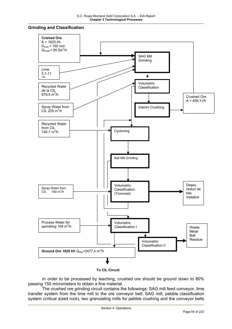
S.C. Roşia Montană Gold Corporation S.A. – EIA Report Chapter 2 Technological Processes
Section 4: Operations
Page 64 of 223
Grinding and Classification
In order to be processed by leaching, crushed ore should be ground down to 80%
passing 150 micrometers to obtain a fine material. The crushed ore grinding circuit contains the followings: SAG mill feed conveyor, lime
transfer system from the lime mill to the ore conveyor belt, SAG mill, pebble classification system (critical sized rock), two granulating mills for pebble crushing and the conveyor belts
To CIL Circuit
SAG Mill Grinding
Interim Crushing
Cycloning
Crished Ore A = 1625 t/h Dmax.= 150 mm Qwater= 85.5m3/h
Ball Mill Grinding
Lime 5,1-11 t/h
Recycled Water de la CIL 679,9 m3/h
Spray Water from CIL 225 m3/h
Volumetric Classification
Volumetric Classification (Trommel)
Volumetric Classification I
Crushed Ore A = 406.3 t/h
Recycled Water from CIL 746,7 m3/h
Spray Water from CIL 160 m3/h
Process Water for sprinkling 109 m3/h
Volumetric Classification II
Ground Ore 1625 t/h Qapa=2477,4 m3/h
Waste Metal Ball Residue
Deşeu resturi de bile metalice

S.C. Roşia Montană Gold Corporation S.A. – EIA Report Chapter 2 Technological Processes
Section 4: Operations
Page 65 of 223
for transportation of the critical sized rock, two ball mills operating in parallel to carry on grinding, two cluster of cyclones to control the ground ore particle size, as indicated on Exhibit 2.13. The grinding circuit is located in an enclosed building and grinding of the critical sized rock will be conducted in a separate building.
The SAG mill feed conveyor belt will be equipped with two weight scales, first located upstream of the conveyor discharge point of the crushed critical sized fraction from the SAG mill - it will ensure weighing of the ore extracted from the stockpile, while the second weight scale is located after the discharge point of the crushed critical size fraction allowing weighing of the combined SAG mill feed.
Prior to grinding, dry lime will be added to the crushed ore (average of 5 t/h, maximum of 11 t/h) ahead of grinding in order to ensure a protective alkalinity in the milling circuit and to create an appropriate pH in the CIL circuit. The grinding circuit feed rate with crushed ore will be 1,625 t/h.
Crushed ore from the stockpile will be fed at a constant rate to the SAG mill processing plant. The SAG mill will have a nominal rated capacity of 13 Mt/a of new feed and will be driven by a 15MW variable speed wrap around electric drive. The SAG mill is provided with a feeding carriage at the SAG feeder. The SAG mill discharge is screened via a trommel to remove coarse particles. The trommel undersize will be directed into a cyclone feed pump box which provides the grinding granulometric control and the oversize (particle size over 12 mm) will be directed to a pebble crusher. An aqueous cyanide solution reclaimed as clear overflow from the CIL tailings thickener. Grinding balls will be added as required to the SAG mill to maintain efficient grinding.
The plant will operate 365 days per year, with continuous service of 24 hours per day, seven days per week.
The critical sized rock (12-100 mm) from the SAG mill trommel undersize (on average 400 t/h, 650 t/h maximum) will be conveyed via a belt system to the two pebble crushers operating in parallel. They will ensure grinding of critical sized rock to 80% less than 12 mm. Crushing capacity of each crusher will be on average 200 t/h with 325 t/h maximum capacity. Special attention will be given to this circuit for the transport of critical sized rock in order to detect and remove any metal (lining, ball scrap etc.) which may enter the crusher to prevent their deterioration. Cleaning magnets shall be strategically placed to remove ferrous metals and a metal detector will provide protection from non ferrous metals. The pebble crusher reduces the pebbles and the crushed material is returned to the SAG mill feed conveyor. The plant will operate on an as required basis.
The trommel undersize will be directed into a cyclone feed pump box which provides the grinding granulometric control and the oversize (particle size over 12 mm) will be directed to a pebble crusher. The ball mill discharged slurry from the second grinding stage will also be directed to the cyclone feed pump box. Two products will be obtained following cycloning:
• The cyclone overflow will flow to a thickening circuit followed by cyanide leaching. • Cyclone underflow, which is the coarse material that reports as feed to the ball mills
for further grinding. The cyclones underflow will be returned to the two ball mills operating in parallel.
Each ball mill is driven by two fixed speed 10.0 MW wound rotor motors. The ball mills discharge over trommel screens designed to scalp out remnant balls and unground material. The scalped ball mill discharges into a concrete bunker where it can be removed by front-end-loader.
During operation the ball load in each of the mills will be measured through power draw readings and grinding balls will be added as required.
In order to improve the trommel screen classification, diluted cyanide solution from the tailings thickener overflow will be sprayed over the outer surface of the screens.
The two stage grinding circuit consisting in grinding in the SAG mill (first stage) with extraction, milling and recycling of the critical sized rock and regrinding using two ball mills operating in parallel (second stage) in closed circuit with two cluster of cyclones will provide an optimal particle size of 80% less than 150 microns.

S.C. Roşia Montană Gold Corporation S.A. – EIA Report Chapter 2 Technological Processes
Section 4: Operations
Page 66 of 223
The cyclone overflow will be discharged by gravity onto two control screens (one for each cluster). The screen underflow residue will be directed by gravity via a pipeline to the leaching circuit and the screen overflow will be routed to two dewatering screens prior to its discharge into two bunkers where it can be removed by front-end-loader, sorted for metal recovery and the remaining material will be transported to the waste stockpile. Water recovered from the dewatering screens will be recycled to the SAG mill feed.
Table 2-18 presents the balance for the main ore grinding and classification operations. Table 2-18 Balance for ore grinding and classification operations
MU ROM ore SAG Mill Feed
Critical Sized Rock
Ball Mill Feed
Cyclone Feed
Cyclone Overflow
Solids t/h 1625 2031.3 406.3 2437.5 3250 1625 Water t/h 85.5 870.5 45.1 104.6 2037.7 2477.4 Slurry m3/h 708.1 1648.8 200.8 1978.6 3282.9 3100
%Solids %w/w 95 70 90 70 61.5 39.6
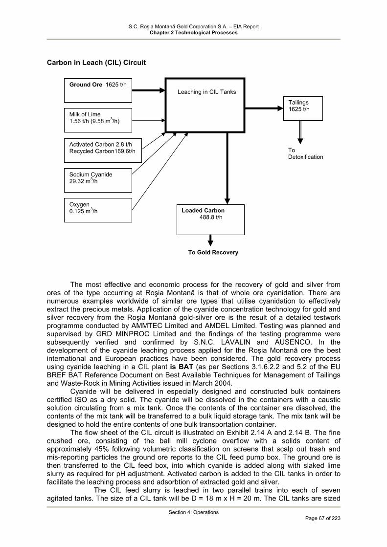
S.C. Roşia Montană Gold Corporation S.A. – EIA Report Chapter 2 Technological Processes
Section 4: Operations
Page 67 of 223
Carbon in Leach (CIL) Circuit
The most effective and economic process for the recovery of gold and silver from ores of the type occurring at Roşia Montană is that of whole ore cyanidation. There are numerous examples worldwide of similar ore types that utilise cyanidation to effectively extract the precious metals. Application of the cyanide concentration technology for gold and silver recovery from the Roşia Montană gold-silver ore is the result of a detailed testwork programme conducted by AMMTEC Limited and AMDEL Limited. Testing was planned and supervised by GRD MINPROC Limited and the findings of the testing programme were subsequently verified and confirmed by S.N.C. LAVALIN and AUSENCO. In the development of the cyanide leaching process applied for the Roşia Montană ore the best international and European practices have been considered. The gold recovery process using cyanide leaching in a CIL plant is BAT (as per Sections 3.1.6.2.2 and 5.2 of the EU BREF BAT Reference Document on Best Available Techniques for Management of Tailings and Waste-Rock in Mining Activities issued in March 2004.
Cyanide will be delivered in especially designed and constructed bulk containers certified ISO as a dry solid. The cyanide will be dissolved in the containers with a caustic solution circulating from a mix tank. Once the contents of the container are dissolved, the contents of the mix tank will be transferred to a bulk liquid storage tank. The mix tank will be designed to hold the entire contents of one bulk transportation container.
The flow sheet of the CIL circuit is illustrated on Exhibit 2.14 A and 2.14 B. The fine crushed ore, consisting of the ball mill cyclone overflow with a solids content of approximately 45% following volumetric classification on screens that scalp out trash and mis-reporting particles the ground ore reports to the CIL feed pump box. The ground ore is then transferred to the CIL feed box, into which cyanide is added along with slaked lime slurry as required for pH adjustment. Activated carbon is added to the CIL tanks in order to facilitate the leaching process and adsorbtion of extracted gold and silver.
The CIL feed slurry is leached in two parallel trains into each of seven agitated tanks. The size of a CIL tank will be D = 18 m x H = 20 m. The CIL tanks are sized
To Gold Recovery
Leaching in CIL Tanks
Ground Ore 1625 t/h
Milk of Lime 1.56 t/h (9.58 m3/h)
Activated Carbon 2.8 t/h Recycled Carbon169.6t/h
Sodium Cyanide 29.32 m3/h
Tailings 1625 t/h
Loaded Carbon 488.8 t/h
To Detoxification
Oxygen 0.125 m3/h
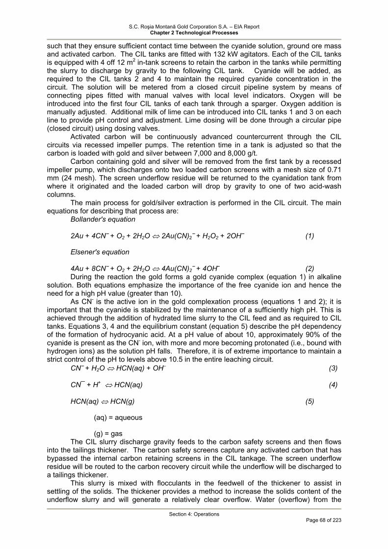
S.C. Roşia Montană Gold Corporation S.A. – EIA Report Chapter 2 Technological Processes
Section 4: Operations
Page 68 of 223
such that they ensure sufficient contact time between the cyanide solution, ground ore mass and activated carbon. The CIL tanks are fitted with 132 kW agitators. Each of the CIL tanks is equipped with 4 off 12 m2 in-tank screens to retain the carbon in the tanks while permitting the slurry to discharge by gravity to the following CIL tank. Cyanide will be added, as required to the CIL tanks 2 and 4 to maintain the required cyanide concentration in the circuit. The solution will be metered from a closed circuit pipeline system by means of connecting pipes fitted with manual valves with local level indicators. Oxygen will be introduced into the first four CIL tanks of each tank through a sparger. Oxygen addition is manually adjusted. Additional milk of lime can be introduced into CIL tanks 1 and 3 on each line to provide pH control and adjustment. Lime dosing will be done through a circular pipe (closed circuit) using dosing valves.
Activated carbon will be continuously advanced countercurrent through the CIL circuits via recessed impeller pumps. The retention time in a tank is adjusted so that the carbon is loaded with gold and silver between 7,000 and 8,000 g/t.
Carbon containing gold and silver will be removed from the first tank by a recessed impeller pump, which discharges onto two loaded carbon screens with a mesh size of 0.71 mm (24 mesh). The screen underflow residue will be returned to the cyanidation tank from where it originated and the loaded carbon will drop by gravity to one of two acid-wash columns.
The main process for gold/silver extraction is performed in the CIL circuit. The main equations for describing that process are:
Bollander's equation
2Au + 4CN⎯ + O2 + 2H2O ⇔ 2Au(CN)2⎯ + H2O2 + 2OH⎯ (1)
Elsener's equation
4Au + 8CN⎯ + O2 + 2H2O ⇔ 4Au(CN)2⎯ + 4OH⎯ (2) During the reaction the gold forms a gold cyanide complex (equation 1) in alkaline
solution. Both equations emphasize the importance of the free cyanide ion and hence the need for a high pH value (greater than 10).
As CN- is the active ion in the gold complexation process (equations 1 and 2); it is important that the cyanide is stabilized by the maintenance of a sufficiently high pH. This is achieved through the addition of hydrated lime slurry to the CIL feed and as required to CIL tanks. Equations 3, 4 and the equilibrium constant (equation 5) describe the pH dependency of the formation of hydrocyanic acid. At a pH value of about 10, approximately 90% of the cyanide is present as the CN- ion, with more and more becoming protonated (i.e., bound with hydrogen ions) as the solution pH falls. Therefore, it is of extreme importance to maintain a strict control of the pH to levels above 10.5 in the entire leaching circuit.
CN⎯ + H2O ⇔ HCN(aq) + OH– (3)
CN¯ + H+ ⇔ HCN(aq) (4)
HCN(aq) ⇔ HCN(g) (5)
(aq) = aqueous
(g) = gas The CIL slurry discharge gravity feeds to the carbon safety screens and then flows
into the tailings thickener. The carbon safety screens capture any activated carbon that has bypassed the internal carbon retaining screens in the CIL tankage. The screen underflow residue will be routed to the carbon recovery circuit while the underflow will be discharged to a tailings thickener.
This slurry is mixed with flocculants in the feedwell of the thickener to assist in settling of the solids. The thickener provides a method to increase the solids content of the underflow slurry and will generate a relatively clear overflow. Water (overflow) from the

S.C. Roşia Montană Gold Corporation S.A. – EIA Report Chapter 2 Technological Processes
Section 4: Operations
Page 69 of 223
thickener will report back to the milling circuit for re-use and recovery of contained cyanide values.
The thickened tailings will then be pumped to a SO2/air cyanide detoxification circuit where the Weak Acid Dissociable cyanide level (WAD Cyanide) in the thickener underflow will be reduced to levels below applicable EU standards. Process tailings management and detoxification method are BAT as per Sections 3.1.6.3, 3.1.6.3.2 şi 4.3.11.8 (The Best Available Techniques for Management of Tailings and Waste-Rock in Mining Activities – Draft March 2004). The detoxified tailings will be pumped as slurry to the tailings management facility. This process is described in detail in Section 2.4.1.2.2.6.
Table 2-10 presents the material balance for the leaching process. Table 2-19 Material balance for the leaching process
MU Slurry from Grinding
CIL Feed Activated Carbon Addition
Cyanide Addition
Loaded Carbon Discharge
Carbon Recycle to the CIL Circuit
Tailings Discharge
Solids t/h 1625 1870.6 16 - 488.8 480.4 1625 Water t/h 2477.4 3014.4 64 32.68 617.6 803.6 2115.6 Slurry m3/h 3100 3727 74 29.32 850 987.8 2737.3
%Solids %w/w 39.6 38.3 20 43.4 37.4 37.4

S.C. Roşia Montană Gold Corporation S.A. – EIA Report Chapter 2 Technological Processes
Section 4: Operations
Page 70 of 223
Acid Wash, Elution and Carbon Regeneration Circuit
Exhibit 2.14 B illustrates the carbon recovery process from the CIL circuit. The acid wash and elution process is illustrated on Exhibit 2.15 and described in detail below. Exhibit 2.24 illustrates the carbon reactivation process.
The CIL tanks are fed with activated carbon particles that adsorb the precious metals
leached by the cyanide. Each tank will have internal screens to prevent the activated carbon particles from discharging from the tank with the residue. The apertures in the internal screens are sized such that the slurry can pass through the screen to the next tank; however, the aperture is too fine to allow the passage of the activated carbon. In this way, the carbon can be contained and managed.
Barren carbon is placed in the last CIL tank where it starts to scavenge precious metal values from the leach residue slurry. As the carbon loads with these precious metals it
Volumetric Classification
Loaded Carbon from CIL tanks 488.8 t/h
Acid Wash
Elution - stripping
Volumetric Classification Dewatering 2.8 t/h
Carbon 480.4 t/h
To CIL Tanks
Thermal Regene-ration 2.12 t/h
Volumetric Classification
Fine Carbon Tank
Activated Carbon Silo 2.9 t/h
Recycled carbon from the screen to tailings circuit 0.78 t/h
Recycled
To TMF
To Gold Recovery 141.6 m3/h

S.C. Roşia Montană Gold Corporation S.A. – EIA Report Chapter 2 Technological Processes
Section 4: Operations
Page 71 of 223
will be periodically pumped counter-current to the leached residue flow to the next upstream tank. The most highly loaded carbon in the first cyanidation tank will be pumped with the residue to one of two loaded carbon recovery screens. The screen underflow residue will be returned to the cyanidation tank from where it originated and the loaded carbon will drop by gravity to one of two acid-wash columns, where it will be washed in a dilute acid solution to remove calcium deposits. This process is described by equation 7.
Ca(OH)2 + 2HCl = CaCl2 + 2H2O (7) Hydrochloric acid will be pumped to the two acid-wash columns from two tanks. The
entire acid wash system consisting of the acid-wash columns - solution tank - centrifugal pump will operate in closed circuit, so that the acid-wash resulting product will be recycled to the solution tank; the residual product will report to the tailings thickener within the CIL circuit. The acid-washed carbon will be neutralised by rinsing with dilute caustic solution, as equation 8.
HCl + NaOH = NaCl + H2O (8) and then transferred to one of two parallel elution columns where a hot cyanide-
caustic solution - at an initial temperature of 105 – 1100C for silver stripping and 125 – 1300C for gold stripping [Anglo American Research Laboratory (AARL) process] will be used to strip the precious metals from the carbon. The heat for the eluate will be provided by the use of liquefied petroleum gas (LPG).
Table 2-20 presents the material balance for the elution - stripping process.
Table 2-20 Material balance for the elution - stripping process
UM Elution Column Feed
HCl SodiumCyanide
Sodium Hydroxide
Fresh Water
Washed Carbon
Pregnant Eluate
Total Water
Solids t/h 2.84 - - - - 34 - - Water t/h 0.5 15.94 28.56 82.66 141.66 136 146.2 155.8 Slurry m3/h 2.28 13.62 25.5 68.87 141.66 157.2 141.6 155.8
% Solids % w/w
85 32 - - - 20 - -
The stripped carbon from each elution column will be pumped to two dewatering
screens operating in parallel. The transfer water will flow by gravity from the dewatering screen to a tank to be reused in the circuit. The carbon from each dewatering screen will drop by gravity into a surge tank feeding a carbon reactivation kiln. Temperature required for carbon reactivation varies between 7000C and 7500C. The fuel used is GPL or electrical power (see the kiln technical sheet of Ausenco 1418-DS-008). The kiln capacity is 1,300 kg/h. Reactivated carbon will be pumped to a sizing screen to remove fine carbon particles. Coarse-sized carbon will drop by gravity into a holding tank and be returned to the last tank of the cyanidation circuit for recovery of precious metals. Fine carbon will be collected in a carbon fines tank as a dilute residue and periodically processed through the carbon fines filter. On average, the amount of regenerated carbon will be of 135 t per week.
Although elution is done on a batch basis, reactivation will be on a continuous basis. Feed hoppers are used to provide surge between elution and reactivation for continuous operation.
Table 2-21 presents the material balance for the carbon reactivation process
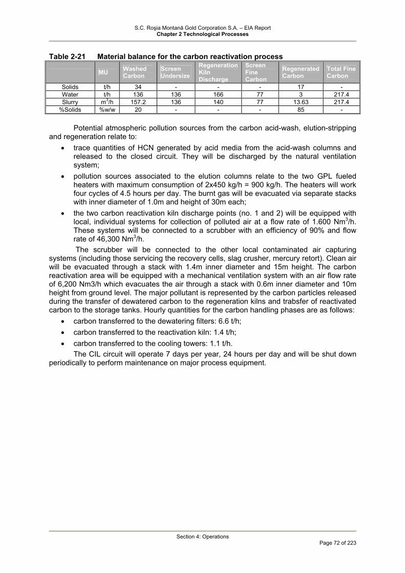
S.C. Roşia Montană Gold Corporation S.A. – EIA Report Chapter 2 Technological Processes
Section 4: Operations
Page 72 of 223
Table 2-21 Material balance for the carbon reactivation process
MU Washed Carbon
Screen Undersize
Regeneration Kiln Discharge
Screen Fine Carbon
Regenerated Carbon
Total Fine Carbon
Solids t/h 34 - - - 17 - Water t/h 136 136 166 77 3 217.4 Slurry m3/h 157.2 136 140 77 13.63 217.4
%Solids %w/w 20 - - - 85 -
Potential atmospheric pollution sources from the carbon acid-wash, elution-stripping and regeneration relate to:
• trace quantities of HCN generated by acid media from the acid-wash columns and released to the closed circuit. They will be discharged by the natural ventilation system;
• pollution sources associated to the elution columns relate to the two GPL fueled heaters with maximum consumption of 2x450 kg/h = 900 kg/h. The heaters will work four cycles of 4.5 hours per day. The burnt gas will be evacuated via separate stacks with inner diameter of 1.0m and height of 30m each;
• the two carbon reactivation kiln discharge points (no. 1 and 2) will be equipped with local, individual systems for collection of polluted air at a flow rate of 1.600 Nm3/h. These systems will be connected to a scrubber with an efficiency of 90% and flow rate of 46,300 Nm3/h. The scrubber will be connected to the other local contaminated air capturing
systems (including those servicing the recovery cells, slag crusher, mercury retort). Clean air will be evacuated through a stack with 1.4m inner diameter and 15m height. The carbon reactivation area will be equipped with a mechanical ventilation system with an air flow rate of 6,200 Nm3/h which evacuates the air through a stack with 0.6m inner diameter and 10m height from ground level. The major pollutant is represented by the carbon particles released during the transfer of dewatered carbon to the regeneration kilns and trabsfer of reactivated carbon to the storage tanks. Hourly quantities for the carbon handling phases are as follows:
• carbon transferred to the dewatering filters: 6.6 t/h; • carbon transferred to the reactivation kiln: 1.4 t/h; • carbon transferred to the cooling towers: 1.1 t/h.
The CIL circuit will operate 7 days per year, 24 hours per day and will be shut down periodically to perform maintenance on major process equipment.
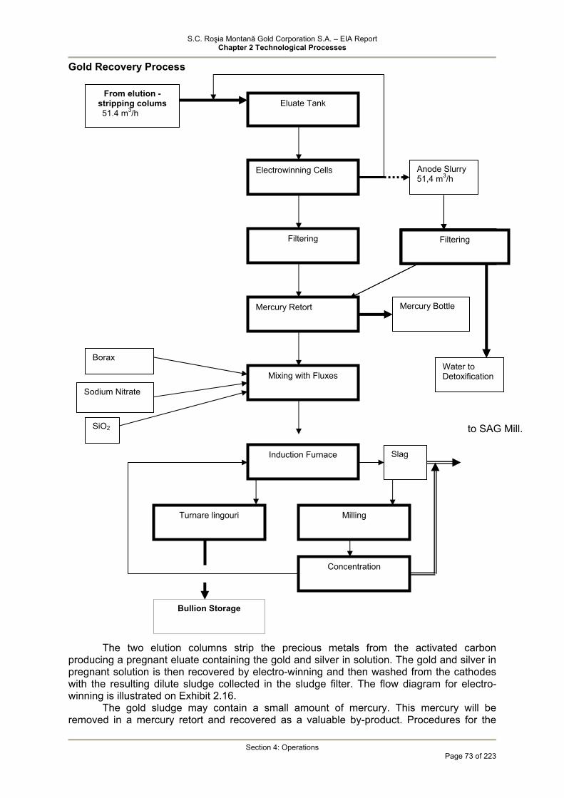
S.C. Roşia Montană Gold Corporation S.A. – EIA Report Chapter 2 Technological Processes
Section 4: Operations
Page 73 of 223
Gold Recovery Process
The two elution columns strip the precious metals from the activated carbon
producing a pregnant eluate containing the gold and silver in solution. The gold and silver in pregnant solution is then recovered by electro-winning and then washed from the cathodes with the resulting dilute sludge collected in the sludge filter. The flow diagram for electro-winning is illustrated on Exhibit 2.16.
The gold sludge may contain a small amount of mercury. This mercury will be removed in a mercury retort and recovered as a valuable by-product. Procedures for the
to SAG Mill.
Induction Furnace Slag
Turnare lingouri
Concentration
Milling
Bullion Storage
Eluate Tank From elution -
stripping colums 51.4 m3/h
Electrowinning Cells Anode Slurry 51,4 m3/h
Filtering
Mercury Retort
Mixing with Fluxes
Mercury Bottle
Borax
Sodium Nitrate
SiO2
Filtrare Filtrare
Water to Detoxification
Filtering
S.C. Roşia Montană Gold Corporation S.A. – EIA Report Chapter 2 Technological Processes
Section 4: Operations
Page 74 of 223
safe handling, storage and transport of the mercury will be included in the Emergency Preparedness and Spill Contingency Plan (see Plan I of the Roşia Montană Project Environmental and Social Management System). The retorted precious metal sludge is then fluxed (borax, sodium nitrate, SiO2) and melted in an induction furnace (operating temperature of 1.2500C). The gold and silver is then heated and poured into ingots. The gold and silver doré will be stored in a secure vault until shipment to precious metal refineries.
Electro-winning Cells
The pregnant eluate will be stored in an eluate tank and pumped to the electro-winning cells in which the gold and silver is plated onto stainless steel cathodes. Carbon elution and electro-winning will operate in batch mode and will be started and stopped one to two times per day depending on the quantities of the metal to be processed.
The gold is deposited at the cathode, as equation 9. Au(CN)2
– + e– → Au + 2CN– (9) Silver is similarly deposited. The electrowinning of gold is accompanied by the
cyanide detoxification at the anode, as equations 10 and 11. CN– + 2OH– → CNO– + H2O + 2e– (10) 2CNO– + 4OH– → CO2 + N2 + 2H2O + 6e– (11) The second reaction does not generally occur due to the cyanide hydrolysis as
equation 12. CNO– + 2H2O → NH4
+ + CO32– (12)
Cathode frames will be designed to slide within the tank, allowing systematic removal of loaded cathodes and insertion of fresh cathodes. The bottom of the cell tanks will slope to a drain allowing periodic flushing of gold sludge from the cell bottom.
Each electrowinning cell will be equipped with a local system for collection of contaminated air. The local collection systems will be connected to the central collection and evacuation facility having a flow rate of 15.400 Nm3/h. The two central facilities will be connected to the above mentioned scrubber.
Specific pollutants consist of metal bearing particles and particles containing ammonium traces. The presence of ammonium may be caused by desorption of ammonium ions in the cells as per the following chemical reactions: CN- + 2OH- → CNO- + H2O + 2 e- CNO- + 2 H2O → NH4
+ + CO32-
Gold Sludge Filter
The gold and silver deposited on the cathodes will be removed as a sludge using high-pressure water sprays. The sludge will be filtered and dewatered in a sludge filter press. The sludge filter will operate in batch mode and will be started and stopped one or more times per day.
The eluate recovered from the electrowinning cell anode area will be collected and filtered. The filter cake will enter the precious metal recovery circuit, while the filtering water will report to the tailings detoxification circuit.
Mercury Retort
Precious metals sludge from the filter press will then be loaded into charge containers (boats) on mobile carts. The boats will be inserted into the mercury retorts (volume of 0,3 m3) without manual precipitate handling. Mercury will be volatilized at a maximum temperature of 6500C and pulled from each retort with a vacuum pump. The gas/vapour directed to flow through a condenser and carbon column. The carbon tower is filled with sulphur-impregnated carbon to specifically capture any mercury vapours not condensed due to process upsets. The sulphur-impregnated carbon will be stored in the Temporary Hazardous Waste Storage Facility under strict security conditions.
Exhibit 2.31 illustrates the mercury recovery, precious metal smelting and processing of slag from the induction furnace flow sheet.
The mercury and sulphur react as equation 13.
S.C. Roşia Montană Gold Corporation S.A. – EIA Report Chapter 2 Technological Processes
Section 4: Operations
Page 75 of 223
Hg(v) + S (s) → HgS (s) (13) Condensed mercury will be captured in the charge tank and stored for recycling
purposes. A total of 0.5 of mercury is estimated to be recovered on a daily basis. The mercury will be collected in sealed containers and stored in the Temporary Hazardous Waste Storage Facility until it is transferred offsite to be recycled via an authorised company.
The mercury retort is equipped with a local installation for capture and evacuation of air loaded with water vapours at a flow rate of 2,600 Nm3/h. This installation will also be connected to the above mentioned scrubber. Given the efficiency of the mercury recovery and emission control system it is estimated that no mercury emission into the atmosphere will occur.
Induction Furnace
The retorted precious metal sludge is then fluxed (borax, sodium nitrate, SiO2) and melted in two induction furnaces, with a capacity of 750 kg each (operating temperature of 1.2500C).
The furnace will operate on a batch campaign basis in association with emptying and filtering of electro-winning cells and retorting. Doré will be cast into 25 kg ingots in a cascade mould. Anticipated operation is three batches per shift to the furnace, with five to 12 shifts per week.
The gold and silver doré will be stored in a secure vault until shipment to precious metal refineries.
The slag from the electrical furnaces will be crushed in a crusher and re-added to the recovery circuit. Initially, the slag will be re-melted. Final slag will be milled and processed on a concentration table. The resulting concentrate will be transferred to the smelting furnaces and the residue will feed the SAG mill.
Local installation for capture and evacuation of air contaminated with fine particulates (gold and silver oxides, oxides of other metals) generated by evaporation of metals and condensation in air will be provided. Each local installation will have a flow rate of 2,500 Nm3/h and will be connected to a scrubber (alkaline environment - NaOH solution - BAT). Air will be evacuated at a flow rate of 5,000 Nm3/h, through a stack with 0.6m inner diameter and 12m height from ground level. The scrubber efficiency is 90%. The slag mill and pulveriser will be fitted with local installation for capture and evacuation of air contaminated with metal particles (mainly) which will be connected to a central installation with a flow rate of 9,700 Nm3/h. The central installation will be connected to the same scrubber used for air decontamination from the carbon reactivation, electrowinning cells and mercury retort.
4.1.2.3 End Products and By-products
The processing of the Roşia Montană gold-siver ore will result in a main end product, i.e. gold and silver ingots. At a design throughput of ore for the processing plant of 13 million tonnes/year, 214.9 million tonnes throughout the life of the Project respectively, a total production of 314.15 tonnes (10,1 Moz) of gold and 1480.5 tonnes (47.6 Moz) of silver is estimated.
In addition to gold and silver, mercury will also be extracted from the ore as a by-product. Mercury will be recovered from the gold bearing slurry resulting from electrowinning. Mercury will be recovered into a mercury retort (volume of 0.3 m3) in an estimated quantity of 0.5kg/day at a rate of 6 days per week. Mercury will be collected in sealed containers and stored in the Temporary Hazardous Waste Storage Facility until it is transferred offsite to be recycled via an authorised company.
4.1.2.4 Process Tailings
The residue generated by the processing of the Roşia Montană gold-silver ore will be represented by the tailings from the processing plant.
Tailings discharged from the process plant consist of a mixture of solids (80% passing 150 microns particle size) and process water. Solids represent 55-60% of the mixture. The tailings unit weight will be of 2,6-2,7 t/m3 depending of the type of ore. It is anticipated that tailings will contain 50-60% particulate matter less than 75 microns.
S.C. Roşia Montană Gold Corporation S.A. – EIA Report Chapter 2 Technological Processes
Section 4: Operations
Page 76 of 223
Testing indicated that the vertical permeability of the settled tailings will vary between 1x10⁻⁴ and 1x10⁻⁶ cm/sec., depending on the type of processed ore and actual consolidation.
Prior to leaving the plant site, the tailings will be treated to reduce the cyanide concentration to a level below the World Bank Guidelines and Directive of the European Parliament and of the Council on the Management of Waste from Extractive Industries and amending Directive 2004/35/EC.
Construction of a tailings deposition pond located in the Corna valley situated immediately to the south of the plant site is required to store the tailings from the gold-silver ore processing plant.
The TMF is being rigorously designed to internationally and nationally accepted standards to provide a facility for the safe and environmentally acceptable storage of the treated tailings. The design has also taken into account the requirements for closure at the end of the mine life.
The tailings generated by ore processing operations, after detoxification to reduce the cyanide concentration to levels that comply with applicable EU and Romanian standards will be transported via pipeline to the TMF. The tailings delivery system is designed for nominal and maximum flows of about 2,350 and 2,730 m3/hr respectively, slurry solids content of up to 48.5% and a minimum discharge velocity of 1.5 m/s.
4.1.3 Industrial Wastewater Treatment
Industrial wastewaters that may occur at mines using cyanide for precious metal recovery are as follows:
• tailings slurry containing cyanide which is normally routed to the tailings pond either treated or untreated.
• decant water containing cyanide which is recycled from the tailings management facility back to the process throughout the operations; under specific conditions or in certain phases of the mining operation water may be discharged to the environment and may require treatment;
• acidic and metal bearing mining impacted water resulting at the contact between stormwater and ARD generating rocks exposed to atmospheric oxygen;
• seepage water from various storage, decant etc. facilities having the same characteristics as the water from the respective facilities; Out of the processes that may be employed for water containing cyanide (tailings
slurry), wastewater with low cyanide concentrations (pond decant water, seepage from the TMF) and ARD water, for the Roşia Montană Project techniques consistent with BAT have been selected.
In order to obtain an accurate understanding of the principles at the basis of selection of the methods employed within the Project, this section will describe other possible techniques including brief data on chemistry and consumptions. Chapter 5 "Alternative Analysis” provides a comparative technical analysis in terms of technological implications of the application of the respective techniques.
4.1.3.1 Cyanide Aqueous System Treatment
The Project aqueous systems containing cyanide are as follows: • tailings slurry resulting from the gold extraction process; • water in the Tailings Management Facility; • TMF seepage;
o During operations: • the tailings slurry will be treated in a detoxification plant and directed to the TMF; the
decant water is recycled back to the process plant representing the majority of the water used for ore processing operations;
• decant water is discharged from the TMF only during abnormal operational conditions, extreme meteorological events, if the designed capacity for 2 successive PMP events is

S.C. Roşia Montană Gold Corporation S.A. – EIA Report Chapter 2 Technological Processes
Section 4: Operations
Page 77 of 223
exceeded and must be treated if the requirements of the NTPA 001/2005 are not met by natural dilution;
• The seepage from the tailings pond will be collected via a sump located upstream of a secondary containment dam and will be pumped back into the TMF basin;
• The passive/semi-passive seepage treatment lagoons for discharge into the Corna Valley will be tested during the last three years of operations.
During normal and abnormal operations or for testing purposes treatment procedures will be applied to all categories of wastewater containing lower or higher concentrations of cyanide and are therefore described below.
These processes may be destructive, recovery or of other type. Useful information regarding the chemistry of processes, operational parameters,
achieved performance and applicability at large operational scale are summarised below.
Destructive processes Alkaline Chlorination
Basic principle - cyanide, WAD cyanide and sulphocyanide oxidation in two steps with chlorigenic compounds (Cl2, NaClO) in alkaline environment, with formation of cyanate as final reaction product.
The process is described by the following sequence of reactions: Oxidation of cyanide: CN- + ClO- + H2O → CNCl + HO- CN- + ClO- → CNO- + Cl- CNCl + 2HO- → CNO- + Cl- + H2O (hydrolysis of chlorinecyan, slightly toxic, alkaline pH) Oxidation of sulphocyanide SCN- + 4OCl- + 2HO-→ CNO- + SO4
2- + 4Cl- + H2O Oxidation of Zn and Cu complex cyanide 2Cu[(CN)3]2- + 7ClO- + 2HO- + H2O → 6CNO- + 7Cl- + 2Cu(OH)2 ↓ Zn[(CN)4]2- + 4ClO- + 2HO- + H2O → 4CNO- + 4Cl- + Zn(OH)2 ↓ Hydrolysis/cyanate oxidation: OCN- + 3 H2O → NH4
+ + HCO3- + HO-
2CNO- + 3ClO- + H2O → N2 + 2CO2 + 3Cl- + 2 HO- (chlorination to break-point, with excess chlorine) Normal Operations
• pH = 10-11.5 (in case of operation at pH < 10 cyanogen chloride occur in the system which is a very toxic comparable with HCN);
• theoretical consumptions: 2,8 g Cl2/g CN- free; 3,8 g Cl2/g CN-u.e.; (actual consumptions:
2-2.5 higher than theoretical consumption) • residence time: 0.5 – 14 h (6 to 8 hours being usual)
Process performance • among the first processes applied at large operational scale for treatment of cyanide
effluents in the mining industry (current limited application for tailings treatment, the process is replaced by SO2/air process);
• applies mainly to the treatment of wastewater containing cyanide; • treatment efficiency above 90% achievable with high reagents consumption (Cl2 = 13,5-
17 g/g CN-t);
• concentrated solutions: ⎯ initial composition: CN-
t = 1-2 g/l; CN-u.e. = 0.7-1.9 g/l, Zn = 110-740 mg/l, Cu = 97-290
mg/l, Fe = 2.4-150 mg/l; ⎯ final composition: CN-
t = 8,3-170 mg/l; CN-u.e. < 1 mg/l, Zn = 3.9-5 mg/l, Cu = 0.38-5 mg/l,
Fe ≤ 53 mg/l. • wastewater with moderate/low cyanide content:

S.C. Roşia Montană Gold Corporation S.A. – EIA Report Chapter 2 Technological Processes
Section 4: Operations
Page 78 of 223
⎯ initial composition: CN-t = 7.5-310 mg/l; CN-
u.e. = 7.1-226 mg/l, SCN- ≤ 330 mg/l, Zn ≤ 93 mg/l, Cu ≤ 10 mg/l, Fe ≤ 9.4 mg/l;
⎯ final composition: CN-t = 1.3-25 mg/l; CN-
u.e. = 0.49-1,2 mg/l, Zn ≤ 1.4 mg/l, Cu ≤ 0.3 mg/l, Fe ≤ 8 mg/l.
Oxidation in the system of SO2/air (INCO, Noranda)
Basic Principle: cyanide and WAD cyanide oxidation using sulphur dioxide or derived substances (sodium sulphite or metabisulphite) to cyanate in the presence of copper catalyst and under specific operating conditions.
The Noranda process uses liquid or gas SO2 while the INCO process uses gas SO2 or in other form in the presence of air.
Free and WAD cyanide oxidation can be described by the following reactions: CN- + SO2 + O2 + H2O → OCN- + H2SO4
M(CN)42- + 4SO2 + 4O2 + 4H2O → 4OCN- + 4H2SO4 + M2+
M2+ = Zn2+, Cu2+, Ni2+, Cd2+ The resulting sulphuric acid is neutralized with Ca(OH)2/NaOH and heavy metals
precipitate as insoluble hydroxides or compounds of Fe-cyan: H2SO4 + Ca(OH)2 → CaSO4 + 2H2O M2+ + Ca(OH)2 → M(OH)2 + Ca2+ 2M2+ + Fe(CN)6
4- → (M)2Fe(CN)6 where M = Zn, Cu, Ni, Cd etc.
Cyanate hydrolysis: OCN- + 3 H2O → NH4
+ + HCO3- + HO-
Operating conditions • presence of copper ions in soluble phase as catalyst • pH = 8-10 • stoichiometric mass ratio SO2:CN-
u.e. = 2.5 g/g CN- (excess of 1.5 - 2 times compared to stoechiometric – practical applications)
• lime mass ratio: SO2 = 2.2 g/g SO2 • reaction time = 20-120 minutes
o Process performance • applicable for cyanide removal from tailings slurry, wastewater; • high treatment efficiencies of more than 90% for tailings slurry treatment; • initial composition: CN-
t = 100-700 mg/l; CN-u.e. = 94-545 mg/l; Cu2+ = 17-275 mg/l;
• final composition: CN-t = 0,4-6 mg/l; CN-
u.e. = 0.1-1 mg/l • the license for the INCO process was granted for some 80 mining sites. Hydrogen Peroxide Oxidation Process
Basic principle - cyanide and WAD cyanide with hydrogen peroxide in the presence of copper catalyst with formation of cyanate under specific operating conditions.
(Degussa Process – H2O2/Cu; Du Pont-Kastone Process - H2O2/Cu + formaldehyde) Cyanide oxidation process (Degussa) with hydrogen peroxide is described by the
following reactions:
CN- + H2O2 CNO- + H2O M(CN)4
2- + 4H2O2 + 2HO- → M(OH)2 ↓ + 4CNO- + 4H2O M = Cd, Cu, Ni, Zn 2Cu2+ + Fe(CN)6
4- → Cu2Fe(CN)6 ↓ CNO- + 2H2O = CO3
2- + NH4+
Operating conditions • pH = 9-11 (optimal pH 9.5-10);
Cu
S.C. Roşia Montană Gold Corporation S.A. – EIA Report Chapter 2 Technological Processes
Section 4: Operations
Page 79 of 223
• theoretical consumptions: 0.7-1.3 g H2O2 /g CN- (actual consumption: 2-5 times higher than theoretical consumption
• reaction time: 0.3 – 4 h • catalyst: 10-20% of CN-
u.e. o Process performance
• Kastone process is used mainly for treatment of residual solutions from galvanic applications;
• Degussa process is applied for treatment of wastewater / slurry with cyanide content (over 20 industrial applications);
• treatment efficiencies higher than 90% for treatment of wastewater with varying cyanide content:
o initial composition: CN-t = 19-1350 mg/l, CN-
u.e. = 19-850 mg/l, Cu = 20-478 mg/l, Fe = 0.1-178 mg/l;
o final composition: CN-t = 0.36-5 mg/l, CN-
u.e. = 0.36-1 mg/l, Cu = 0.4-5 mg/l, Fe = 0.1-2 mg/l.
Caro’s Acid Oxidation Process (Efflox)
Basic Principle - oxidation of cyanide, WAD cyanide and sulfocyanides with Caro’s acid (peroxymonosulphuric acid - H2SO5) with formation of cyanate.
The process can be described by the following reactions: H2SO4 + H2O2 → H2SO5 + H2O H2SO5 + CN- → OCN- + SO4
2- + 2H+ 4 H2SO5 + SCN- → OCN- + 5 SO4
2- + 10 H+ 4 H2SO5 + M(CN)4
2- → 4 OCN- + 4 SO42- + 8 H+
Operating conditions • Caro’s acid preparation: on- site due to high instability; • reaction time: on the order of minutes; • theoretical consumption: 4.39 g H2SO5 / g cyanide (actual consumptions: 1.5-2 times
higher than theoretical consumption); • use of lime for H2SO4 neutralization (pH = 8,5-9); • a catalyst is not required;
o Process performance • relatively recently developed process, it is to be applied at industrial scale. CombinOx Technology
Basic Principle: combination of the oxidative processes based on SO2/Air and peroxides (hydrogen peroxide or Caro’s acid), reagents are a combination of peroxide, sulphur dioxide and air and Cu2+ catalyst.
The process can be described by the following reactions: CN- + H2SO5 → OCN- + H2SO4 CN- + SO2 + O2 + H2O → OCN- + H2SO4 Operating conditions are similar to the basic processes (INCO + Degussa/Caro). The process is recommended for slurry treatment being currently under development
(not applied on an industrial scale).
Ozone oxidation Basic principle - cyanide and complex cyanide oxidation using ozone with formation
of cyanate as interim product, the final reaction products are bicarbonate and nitrogen. Chemical reactions:

S.C. Roşia Montană Gold Corporation S.A. – EIA Report Chapter 2 Technological Processes
Section 4: Operations
Page 80 of 223
Operating conditions / Performance
• theoretical consumptions: 1.2 – 1.4 ozone moles/cyanide moles (excess of 1.5 - 2 times compared to stoechiometric – practical applications for wastewater)
• oxidation efficiency over 90%, not applied in the within the mining industry.
Electrochemical oxidation Basic Principle - this method destroys by electrolytic process the cyanide at the
anode while heavy metals are collected at the cathode; reaction products are CO2 and N2 are not toxic.
The chemistry of the electrochemical oxidation process for Ag cyanide is as follows: Anode
CN- + 2OH- → CNO- + H2O + 2e- [Ag(CN)3]2- + 6OH- → Ag2+ + 3CNO- + 3H2O + 5e- 2CNO- + 4OH- →2CO2(g) + N2(g) +2H2O + 6e-
Cathode: Ag2+ + 2e- → Ag(s) Process efficiency is a function of pH, current density and voltage cell and type of
electrodes. The process is currently under development.
Biological Processes Basic principle - biological processes use continuous flow systems, with attached
biomass (biofilters) or suspended biomass (active sludge), and they are able to remove cyanides, thiocyanates, cyanates, ammonia and metals (by a biosorption process) from these dilute solutions. Bacteria will transform both free cyanide and cyanide in heavy metal complexes in bicarbonate and ammonia while released metals are absorbed by a biofilm or are precipitated from aqueous phase.
Cyanide biodegradation in the presence of bacteria bacterii (Pseudomonas sp., Alcaligenes sp., Arthrobacter sp.), fungi (Fusarium solani) si alge (Chlorella vulgaris) takes place according to the following scheme:
Biological Treatment Alternatives:
• Sequential aerobic biological treatment (industrial application: pH > 9, t >10°C, TRH >45 h, presence of nutrients with P + oxygen):
• aerobic biological treatment with active sludge providing: cyanide removal from cyanate, thiocyanate complexes and ammonia nitrification, respectively (applied reagents: sodium carbonate, phosphoric acid, air);
• anaerobic biological denitrification (addition of methanol - carbon sources, phosphoric acid, sulphuric acid - pH adjustment) - only for high nitrate concentrations;
• removal of precipitated metals and arsenic (FeCl3, flocculants); • decant/settling in one or two stages; • anaerobic biological treatment in enclosed buildings (laboratory scale application with
free culture or submersed biofilters with active carbon support) under the following conditions:
• application of primary carbon source (methanol/ethanol, phenol);
Microorganisms Microorganisms Microorganisms
Nitrificatio
CN-
NH3
HCO3NO2
-
Nitrification
NO3-

S.C. Roşia Montană Gold Corporation S.A. – EIA Report Chapter 2 Technological Processes
Section 4: Operations
Page 81 of 223
• CN- initial ≤ 130 mg/l; • TRH ~ 41 h • t = 30-40°C • CN- residual ≥ 1 mg/l
Recovery processes: AVR Process: acidification-volatilization (air stripping)-reneutralisation
Basic Principle: the process is applicable to slurries and solutions and consists of decreasing the pH between 2-3 using sulphuric acid or sulphur dioxide, stripping of HCN, followed by HCN absorption into an alkaline solution of NaOH or Ca(OH)2. The recovered cyanide is recycled back to the gold extraction process.
The process can be described by the following reactions: CN-
(aq) + H+ → HCN(g)↑ HCN(g) + NaOH(aq) → NaCN(aq) The effluent of the desorption phase is neutralized with lime to a slightly alkaline pH
in view of separation of solids and subsequent finishing of supernatant quality, according to discharge requirements.
Operating conditions • pH = 2-3 (pH adjustment agent: H2SO4 or SO2) • stripping agent: air • alkaline solution for capturing of HCN (NaOH or Ca(OH)2 • CN-
u.e. > 150 mg/l Process performance The process can be applied at efficiencies over 80% for recovery of HCN from
slurry/decant water. Slurry: 35-45% solids; CN-
u.e. = 250-600 mg/l; η = 80-90% (CN-u.e. residual = 25-120
mg/l) Decant water: CN-
u.e. = 350-550 mg/l; η = 96% (CN-u.e. residual = 14-22 mg/l).
Limited industrial applications at flow rates ≤ 100 t slurry/h.
Recycling of cyanide effluents Basic Principle: slurry thickening at ~ 40% solids in the presence of polyelectrolytes
at ~ 60% solids and aqueous phase recycling to the main process (grinding circuit). The process is currently applied at gold ore processing facilities, Process performance - cyanide recovery, reduction of cyanide concentration in the
slurry reporting to the detoxification circuit, reduction of power and reagent consumption, minimisation of operating costs.
Ion exchange processes (Vitrokele, Augment)
Basic Principle: the technologies are based on strong basic ion exchange resins that are able to retain and recover WAD and free cyanide from solutions (settled water).
Main reactions: • Adsorption cycle: 2(Resin+ X-) + M(CN)42- = (Resin+)2M(CN)42- + 2X- • Recovery cycle: (Resin+ )2M(CN)4
2- + 2H2SO4 = (Resin+)2(SO)42- + MSO4 + 4HCN
• HCN recovery by stripping + adsorption in alkaline solution. Process performance - process applied at laboratory/pilot scale as final treatment
stage for water with low cyanide and heavy metal content. Influent Composition: CN-
t = 1.7 mg/l; CN-u.e. = 1.2 mg/l; Cu = 0.39 mg/l; Zn = 0.09
mg/l; Ag = 0.9 mg/l; Hg = 0.014 mg/l. Effluent Composition (48 operation hours): CN-
t = 0.19 mg/l; CN-u.e. = 0.19 mg/l; Cu =
0.01 mg/l; Zn = 0.02 mg/l; Ag = 0.01 mg/l; Hg = 0.014 mg/l.

S.C. Roşia Montană Gold Corporation S.A. – EIA Report Chapter 2 Technological Processes
Section 4: Operations
Page 82 of 223
Adsorption on Activated Carbon. Basic Principle: retaining of mainly complex cyanide on coarse or fine activated
carbon from water with low concentrations of cyanide/heavy metals and cyanide recovery by acid stripping - adsorption in alkaline solution.
Operating conditions • CN-
initial < 2 mg/l;
• addition of metal ions (Cu/Ni) for complexing/improvement of the adsorption process • contact time min. 10 minutes
Process performance: • process applied at laboratory/pilot scale for final treatment of effluents without
suspended particles with low residual cyanide and heavy metal content and with cyanide recovery.
• influent characteristics: CN-t = 1.7 mg/l; CN-
WAD = 1.2 mg/l; Cu = 0.39 mg/l; Ag = 0.9 mg/l
• effluent characteristics: CN-t = 0.15 mg/l; CN-
WAD = 0.02 mg/l; Cu = 0.02 mg/l; Ag = 0.05 mg/l
• adsorption capacity 14 mg CN-/g activated carbon (KCN synthetic solution) NOTE: in the presence of active oxygen and copper ions the process of cyanide
adsorption on carbon turns into a process of catalytic oxidation with generation of cyanate ions.
Other Processes: Precipitation Processes
Basic Principle: precipitation of free and WAD cyanide, in the presence of ferrous ion, in the form of insoluble complexes.
The process can be described by the following reactions: Fe+2 + 6CN- + ¼O2 + H+ → Fe(CN)6
-3 + ½H2O 4Fe+2 + 3Fe(CN)6
-3 + ¼O2 + H+ → Fe4[Fe(CN)6]3 + ½H2O Operating conditions
• pH = 5 - 6 • addition of Fe as hydrated sulphate (FeSO4 7H2O) • theoretical consumption 0.5 – 5.0 Fe mols/CN- mol according to the required
treatment level • reaction time: 15 – 30 minutes
Process performance: • reduction of CN-
u.e. from soluble phase under 5 mg/l.
Natural Degradation Basic Principle: involves high retention times in the settling ponds. The main physical-chemical and biological processes involved in the reduction of
cyanide concentrations in aqueous phase are as follows: • volatilsation • precipitation • photochemical degradation • chemical oxidation • biological oxidation • hydrolysis • adsorption on solids

S.C. Roşia Montană Gold Corporation S.A. – EIA Report Chapter 2 Technological Processes
Section 4: Operations
Page 83 of 223
Factors influencing the degradation process are the following: species and concentration of cyanide in the aqueous phase, pH, temperature, light intensity, oxygen concentration, nature of existing bacteria and pond characteristics (surface, depth, turbidity, turbulence, presence of ice) Typical cyanide concentration reduction reactions in settling ponds are as follows: Volatilization
Zn(CN)4
2- ⇔ Zn2+ + 4CN- CN- + H2O ⇔ HCN(aq) + OH- CN- + H+ ⇔ HCN(aq) HCN (aq) → HCN(g)
(g) = gaz
Precipitation with formation of complexes
2M2+ + Fe(CN)64- ⇔ M2Fe(CN)6 (s)
Photochemical degradation (UV radiations)
[Fe(CN)6]3- + H2O [Fe(CN)5H2O]2- + CN-
Sulphocyanide formation 2S2- + 2CN- + O2 + 2H2O ⇔ 2SCN- + 4OH-
S2O32- + CN- ⇔ SCN- + SO3
2-
Cyanate oxidation-hydrolysis CN- + ½ O2 ⇔ OCN-
OCN- + 3H2O ⇔ NH4+ + HCO3
- + OH-
Aerobic biodegradation 2CN- + O2 ⇔ 2OCN-
Adsorption (Me-OH – mineral surface) Me-OH + CN- ⇔ Me-CN + OH-
Hydrolysis/saponification HCN + 2H2O = NH4COOH (formiat de amoniu) HCN + 2H2O = NH3 + HCOOH (acid formic)
Among the listed natural degradation processes, volatilization is the most important. pH reduction in settling ponds (adsorption of CO2 from air, low pH rainwater)
generates partial decomposition of metallic-cyanic complexes with formation of free cyanide. At lower pH, most of the cyanide occurs as HCN (pH = 9, HCN = 69.6%; pH = 8, HCN = 95.8%; pH = 7, HCN = 99%), evaporated naturally as vapours.
DTOX Process
Basic Principle: conversion of cyanide to thiocyanate which is less toxic and precipitation of metals using polysulphides (NaSx, 39%).
Possible applications: detoxification of wastewater with cyanide content (testing at laboratory/pilot scale)
4.1.3.2 Treatment of Aqueous System with Cyanide Content - Roşia Montană Project
The advanced processes for the treatment of tailings slurry and wastewater resulting from ore processing activities conducted at Roşia Montană are described below.
Inco SO2/air detoxification process on the tailings slurry
Application of the INCO process (SO2/air oxidation) for treatment of the Roşia Montană tailings slurry is based on the following considerations:
• the INCO process has been identified by the BREF BAT Reference Document on Best Available Techniques for Management of Tailings and Waste-Rock in Mining Activities as the current alternative for the treatment of aqueous systems with cyanide content (over 80 industrial applications);
• conclusions of the lab/pilot tests on slurry from the cyanidation of the Roşia Montană ore conducted for the purpose of selecting the optimal cyanide oxidation alternative (tested processes: INCO-SO2/air, Efflox-Caro’s acid, Degussa-H2O2/Cu, Combinox – SO2/H2O2/Cu);

S.C. Roşia Montană Gold Corporation S.A. – EIA Report Chapter 2 Technological Processes
Section 4: Operations
Page 84 of 223
• treated slurry quality must comply with the tailings pond discharge limits provided by the Directive of the European Parliament and of the Council on the management of waste from the extractive industries with reference to the CN-
u.e. indicator; the Roşia Montană Projects will develop a new mine therefore the limit value of 10 mgCN-
u.e./L must be met.
• technological implications, capital and operational costs on industrial scale. The cyanidation of the Roşia Montană gold ore (Cîrnic and Cetate mines) as per the
basic technology generated a slurry considered representative for the first 7 years of operations and assessment of the slurry quality requiring treatment prior to discharge to the deposition pond. The variation ranges of the contamination indicators for slurry samples with 50% solids collected during testing conducted in 2001 (Oretest Laboratory, Perth Australia, INL Pty LTD) and 2004 (Cyplus GmbH in collaboration with INCO Technical Services Limited) are as follows:
• pH = 10.3-10.5 • CN-
total = 165 – 290 mg/l • CN-
u.e. = 159 - 260 mg/l • CN-
free = 169 – 210 mg/l • Cu = 9 – 40 mg/l • Fe = 1.03 – 3.4 mg/l • Mn ≤ 0.8 mg/l • As ≤ 0.3 mg/l • SCN- = 66 – 108 mg/l
Table 2-22 summarises the characteristics of the slurry samples. The data shows the specific aspects related to the composition of the aqueous phase
in the slurry, as follows: • relatively low concentrations of total cyanide (CN-
t < 300 mg/l) mainly as WAD cyanide (CN-
u.e = 88-95% din CN-t);
• low concentration of heavy metals on the order of mg - tens mg/l due to the high percentage of free cyanide (CN-
free = 80% of CN-u.e.) in the aqueous system.
• presence of copper as catalyst in oxidation processes in concentrations of tens mg/l (Cu ≤ 44 mg/l);
• relatively low content of sulphocyanide (SCN- ≤ 108 mg/l), oxidisable contaminant; • low concentration of arsenic (As < 0,3 mg/l).
The specific nature of the soluble phase related to composition, composition are beneficial for the efficient application of the oxidation processes, with the mention that the reagent doses are also influenced by the behaviour/stability of the oxidation agents in the presence of the solid phase in the tailings composition.
The testing conducted for the selection of the best slurry treatment process aimed primarily at establishing the working conditions necessary for the CN-
u.e. oxidation to residual concentrations of 50 mg/l, 1 mg/l (soluble phase), respectively.
The results of the tests performed for the INCO (SO2/air) process and alternate options are summarised in Tables 2-23, 2-24 and 2-25, with the specification of the initial composition following treatment and 48 hours after the completion of testing (post-reaction simulation in the settling pond at different temperatures) as well as the working conditions (pH, contact time, reagent doses). It should be mentioned that the untreated slurry samples were re-analyzed for each test, resulting insignificant differences in pollutant concentrations compared with the duplicate samples (Table 2-22).
The tests conducted by Cyplus/INCO in 2004 for slurry detoxification are the most relevant, a total of 20 tests being performed at lab / pilot scale for final determination of the operating parameters.
S.C. Roşia Montană Gold Corporation S.A. – EIA Report Chapter 2 Technological Processes
Section 4: Operations
Page 85 of 223
The analysis of the resulting data indicates the following: • INCO procedure can ensure obtaining of residual concentration CN-
u.e. < 5 mg/l (0,2-3,2 mg/l) by adequate control of the operating parameters (modification of SO2/CN-
u.e., pH ratio, contact time, catalyst addition, if applicable); • The alternatives (Caro’s acid, H2O2/Cu, CombinOx) under specific testing conditions
do not lead to the obtaining of residual values of CN-u.e on the order of mg/l, except
in the case of the H2O2/Cu process (high excess of oxidation agent). In conclusion, it was considered that the SO2/air process represents the optimal
alternative for tailings slurry treatment, an additional argument being the a large scale use of the INCO technology in the mining industry (over 80 applications at industrial scale).
The results obtained at the lab / pilot scale constituted the database for the
development of a consistent tailings slurry treatment flow sheet in view of subsequent discharge to the TMF. The main phases are as follows:
• Phase I – partial recovery treatment by recycling (slurry thickening to 60% solids content – recycle of decant water with cyanide content to the process plant – slurry dilution to 50% solids content – reporting to the DETOX Plant).
• Phase II – advanced destructive treatment of tailings slurry (50% solids content) applying the INCO (SO2/air) process in the DETOX plant. The INCO treatment technology, which uses sodium metabisulphite as soluble
sulphur dioxide source can ensure high efficiencies of over 97% reported for CN-u.e. indicator;
the reaction conditions are the following: • pH = 8.5-9 (milk of lime dosing) • SO2:CN-
u.e. = 3.1-4/1 (mass ratio) • reaction time ≤1.5 ore • Cu2+ ≤ 40 mg/l
The application of the process largely ensures the removal of all forms of cyanide (free, WAD, complex cyanide) by oxidation reactions – precipitation and also removal of heavy metals (precipitation as insoluble hydroxides/cyanic complexes of Fe).
Table 2-26 shows the complete physical – chemical characterization for the cases considered by Cyplus/INCO as representative (treated slurry sample RM1 –RM3 ).
According to the Cyplus/INCO specialists, based on the results obtained at pilot / lab scale conducted on actual samples, it is considered that the residual level of CN-
u.e. at industrial scale (adequate operating conditions) will be max 5 mg/l, in any case below the EU Directive limit level of 10 mg/L.
The INCO process is flexible, enabling the adjustment of the operational parameters to likely variations of composition (total cyanide levels higher than 300 mg/l, disadvantageous CN-
u.e. and CN-t ratios below 0.8, low copper concentrations etc.) by
changing the SO2/CN-u.e. ratio, additional catalyst dosage etc. However, the influence of the
temperature (t ≤ 10°C) on the treatment efficiency was not analyzed, due to some inconsistent information regarding this parameter.
Some scientists including the developers of the technology state that the effect of the temperature on the process performances is not significant within the 5-60°C range (Smith A., Mudder T – The Chemistry and Treatment of Cyanidation Wastes, Mining Journal Book 1991, page 304).
Other scientists consider that the temperature is a process limiting factor because the reaction speed can decrease 10 times if the temperature drops from 25°C to 5°C (Technical Report Treatment of Cyanide Heap Leaches and Tailings – Sep.1994, US-EPA 530-R-94-037, page 8).
In conclusion, the followings are required:

S.C. Roşia Montană Gold Corporation S.A. – EIA Report Chapter 2 Technological Processes
Section 4: Operations
Page 86 of 223
• To support the information regarding the insignificant influence of low temperatures taking into account the direct implications on the reaction volumes, particularly for high slurry flow rates (Q ~ 2300 m3/h);
• It is mentioned that the sizing of the slurry treatment reactors was performed for reaction times higher than those determined experimentally.
• A comparative presentation of the tailings slurry treatment efficiencies (initial and final composition) achieved at industrial scale in facilities located in areas with low winter temperatures.

S.C. Roşia Montană Gold Corporation S.A. – EIA Report Chapter 2 Technological Processes
Section 4: Operations
Page 87 of 223
Table 2-22 Physical-chemical composition of tailings slurry (50% MTS)
No. Indicator T1 / T6 (Lakfield Oretest 2001)
RM (sample A7505) (IML Pty LTD 2001)
RM1-3A
(Cyplus/Inco 2004)
1 pH 10.5 10.3 10.5
2 CN-totale, mg/l 230 290 165 – 187
3 CN-u.e., mg/l 210 260 159 – 184
4 CN-libere, mg/l 177 / 169 210 -
5 SCN-, mg/l 97 / 108 80 66 -90
6 CNO-, mg/l 830 / 170 110 310 - 110
7 Cu, mg/l 9 / 10 - 13.1 – 40.3
8 Ni, mg/l 0.1 / 5.3 - 0.32 – 0.8
9 Zn, mg/l 6.2 / 5.2 - 7.8 – 11.6
10 Fe, mg/l 3.4 / 1.9 - 1.03 – 2.3
11 Cd, mg/l - - < 0.05
12 Co, mg/l - - 0.3 – 0.4
13 Mo, mg/l - - 0.19 – 0.3
14 As, mg/l - - ≤ 0.3
15 Mn, mg/l - - ≤ 0.8
16 Sb, mg/l - - 0.02-0.24
17 NH3, mg/l - - -

S.C. Roşia Montană Gold Corporation S.A. – EIA Report Chapter 2 Technological Processes
Section 4: Operations
Page 88 of 223
Table 2-23 INCO (SO2/aer) Process – Summary of the results of the testing conducted by Cyplus/Inco for final determination of the operational parameters
Influent, mg/l Effluent, mg/l No. Type of Slurry CN-
t CN-u.e. Cu CN-
t CN-u.e. Cu
Comments
0.9-2.4 0.2-1.6 0.23-2.5 1 RM1 164-192 161-190 41.7-45.2
0.55-1.5* 0.1-0.9* 0.08-1.58*
2.4-3.9 0.4-1.4 0.14-0.8 2 RM2 158-185 154-182 12.8-16.4
2.1-2.2* 0.2-0.4* 0.07-0.38*
1.8-2.1 0.1-0.3 0.13-0.23 3 RM3 155-156 153-154 11.8
2-1.6* 0.2* 0.03-0.04*
Working Conditions
⎪⎪⎩
⎪⎪⎨
⎧
=
=
−=
=−=
+
−
60minrτ5) of sample (1 mg/l 5additionalCu
4,2/12,9(g/g)CN:SO
5) of samples (3 8,5pH 9;8pH
1RM2
u.e.2
⎪⎪
⎩
⎪⎪
⎨
⎧
==
−=
=−=
+
−
)90'at 6 of samples (2min 60/90rτ6) of ample (1 5mg/ladditionalCu
6.3/13.2(g/g)CN:SO6)din proba (1 8pH;5.88pH
2RM2
u.e.2
⎪⎩
⎪⎨
⎧
==
=−
min 60rτ5/1-4(g/g)CN:SO
5.8pH
3RM u.e.2
Provenance of cyanide leached ore: RM1 – 80% Carnic + 20% Cetate RM2 – 33% Carnic + 67% Cetate RM3 – 100%Carnic
* After 48 h treated surry residence at ambient temperature (post-reaction simulation in the pond) Note: Total tests – 13/19 (criteria- post-reaction conditions) Source of SO2 -Na2S2O5 (sodium metabisulphite)
Reference: Cyplus/INCO 2004 – Test Program to Evaluate Cyanide Destruction Option Using SO2/Air and Peroxygen-Based Technologies for the Treatment of Rosia Montana Leach Effluent

S.C. Roşia Montană Gold Corporation S.A. – EIA Report Chapter 2 Technological Processes
Section 4: Operations
Page 89 of 223
Table 2-24. Treatment of tailings slurry from the Roşia Montană ore processing activities applying the INCO (SO2/aer) process Influent, mg/l Effluent, mg/l No. Ore
Sample pH CNt- CN-
u.e. Cu Zn Fe pH CNt- CN-
u.e. Cu Zn Fe Reference
1 6 10.2 250 220 20 5.2 2.9 9.8-9.0 - 54/29* 11/11* - -
2 6 10.2 250 220 20+10 5.2 2.9 9.5-8.8 - 7/8.7* 21/21* - -
3 6 10.2 250 220 20+10 5.2 2.9 9.5-8.6 - 3.2/0.7* 20/8* - -
4 6 10.2 250 220 20+40 5.2 2.9 9.3-8.0 - 8.6/0.2* 42/10* - -
5 6 10.2 250 220 20+10 5.2 2.9 8.5-7.4 - 18/23* 21/17* - -
6 6 10.2 250 220 20+40 5.2 2.9 8.7-7.3 - 1.8/2.4* 1.4/1* - -
Lakfield
Oretest/2001
7 RM1 10.5 183 180 43.8 7.8 1.05 8.5/8.1* 1.24/1.24* 0.37/0.43* 0.3/0.24* 0.01 0.33
8 RM2 10.5 165 159 19.1 8.9 2.3 8.5/8.6* 5.09/4.1* 0.77/0.48* 0.2/0.18* 0.3 1.7
9 RM3 10.5 187 184 13.1 11.6 1.03 8.5/7.9* 3.29/4.09* 0.22/0.28* 0.2/0.1* <0.01 0.96
Cyplus/Inco 2004
Operating Conditions (1-9) Reaction Time Reagent Consumption
Provenance of cyanide leached ore 6, RM3 – 100%Carnic
RM1 – 80% Carnic + 20% Cetate RM2 – 33% Carnic + 67% Cetate
Note: RM1-RM3
⎩⎨⎧
≤−=−
%2%9.116.1/ 2
StSS
τ1; τ2; τ3; τ4 = 120 min τ5; τ6 = 180 min τ7 = 60 min; τ8; τ9 = 90 min poz. 2÷6 addition of extra Cu
% stoech
MBS 1-3, 5 – 143% MBS 4, 6 - 170%
SO2/ CN-WAD (w/w)
RM1 → 4 RM2→ 6.2
RM3 → 3.7
* After 48 h treated slurry residence at a temperature of 50C (post-reaction simulation in the pond in the most adverse conditions) Note: MBS (Na2S2O5 –sodium metabisulphite) – souce of SO2

S.C. Roşia Montană Gold Corporation S.A. – EIA Report Chapter 2 Technological Processes
Section 4: Operations
Page 90 of 223
Table 2-25 Alternative processes tested for treatment of tailings slurry from the Roşia Montană ore processing activities Influent, mg/l Effluent, mg/l
No. Applied Process Ore Sample pH CNt
- CN-u.e. Cu Zn Fe pH CNt
- CN-u.e. Cu Zn Fe
Reference
6 10,2 250 220 20+10 5,2 2,9 10 - 38/22* 21/22* - - 1-2 CARO’S ACID
6 10,2 250 220 20+20 5,2 2,9 8,5 - 31/5,8* 17/22 - -
6 10,2 250 220 20+10 5,2 1,9 10 - 82/51* 22/23* - - 3-4
HYDROGEN
PEROXIDE 6 10,2 250 220 20+40 5,2 1,9 8,5 - 1/0,7* 1/2* - -
Lakefield
Oretest/2001
RM1 10,5 173 170 42,4 7,1 1,12 8,8 47 45 32 0,72 0,73 5-6 COMBIN OX
RM2 10,5 165 160 17,2 7,3 1,7 8,9 50 47 14,6 0,08 1,19
Cyplus/Inco
2004
Provenance of cyanide leached ore 6 – 100% Carnic
RM1 – 80% Carnic + 20% Cetate
RM2 – 33% Carnic + 67% Cetate
Operating Conditions (1-6) Reaction Time Reagent Consumption (% stoech)
τ1; τ3 = 120 min Caro/1 – 120%
τ2; τ4 = 180 min Caro/2- 200%
τ5 = 60 min; τ6 = 90 min H2O2/3 – 300%
H2O2/4 – 800%
* After 48 h treated slurry residence at a temperature of 50C (post-reaction simulation in the pond in the most adverse conditions)

S.C. Roşia Montană Gold Corporation S.A. – EIA Report Chapter 2 Technological Processes
Section 4: Operations
Page 91 of 223
Table 2-26 Physical-chemical characteristics of treated slurry (representative samples – laboratory / pilot scale
Determined Levels No. Indicator
RM1 RM2 RM3A
1 pH 8.5 8.5 8.5
2 CN-TOTAL, mg/l 1.13 5.09 3.29
3 CN-WAD., mg/l 0.37 0.77 0.22
4 Zn, mg/l < 0.2 < 0.1 < 0.2
5 Cu, mg/l 0.1 0.1 0.1
6 Fe, mg/l 0.2 1.4 1
7 Ni, mg/l 0.2 0.4 0.2
8 As, mg/l 0.3 < 0.2 0.2
9 Mn, mg/l 0.3 0.8 < 0.1
10 Ca, mg/l 401 675 707
11 Co, mg/l 0.4 0.4 0.8
12 Sb, mg/l SLD 0.28 0.06
13 SCN-, mg/l 70 69 91
14 CNO-, mg/l 390 390 350
15 NH3 , mg/l 6.6 7.3 25
Reference: Cyplus/INCO 2004 – Test Program to Evaluate Cyanide Destruction
Option Using SO2/Air and Peroxygen-Based Technologies for the Treatment of Rosia Montana Leach Effluent.
Summary description of the tailings slurry treatment plant
The Project will use the Best Available Technique for cyanide detoxification through the employment of the Inco SO2/air detoxification process on the tailings discharge residue. This is a proven technology that has been adopted in more than 80 mines worldwide.
The WAD cyanide concentration will be reduced to levels below the 10 mg/L limit imposed by the EC Directive - Management of waste from the extractive industries for discharge of treated slurry to the TMF.
Drawing 2.3 illustrates the treatment flow sheet including slurry balance and composition elements by phases of process
DETOX Plant
The slurry from the final CIL tanks of each line (tank 7 and 14, respectively) will be subject to classification for recovery of activated carbon.
Tailings from the CIL section of the process plant will be routed to the tailings thickener, where process water containing cyanide will be recovered in the tailings thickener overflow and returned to the grinding circuit for re-use. The thickening-settling process occurs in the presence of flocculants (Magnafloc 155 – specific consumption of some 0.04kg/t).
Drawing 2.3 illustrates the tailings slurry detoxification process flow sheet (thickening - INCO oxidation).
The cyanide detoxification facilities will consist of two tanks operating in parallel and ensuring a reaction time of 90 minutes.
Treated water or freshwater will be added to the cyanide detoxification feed header to dilute the underflow of tailings thickener from normally 60% solids to 50% solids.
S.C. Roşia Montană Gold Corporation S.A. – EIA Report Chapter 2 Technological Processes
Section 4: Operations
Page 92 of 223
Water addition will be based on density and flow measurements of the thickener underflow. The resulting diluted thickener underflow will be directed to the two tanks of the cyanide detoxification facilities.
Compressed air, provided by four compressors discharging at a pressure of 250 kPa, will be added to each tank through a sparger. Airflow will be controlled at each tank through a rotameter.
The source of SO2 is sodium metabisulphite – (Na2S2O5) a solution that will be metered into each tank. The addition rate of SO2 will be based on the concentration of WAD cyanide in the tailings stream and the tailings solution flow. The cyanide concentration will be determined by the plant operator and input to the control system. The detoxification reactor feed flow is measured and the mass flow of cyanide is calculated by the control system. The control system then adjusts the flow of the SO2 to effect detoxification.
A copper sulphate (CuSO4) solution will be metered into each tank to maintain a required concentration of copper ion in solution to catalyse the detoxification reaction.
Because of the composition of the Roşia Montană ores and the resulting fluid chemistry, copper sulphate may not need to be routinely added to maintain the required copper concentration. Copper sulphate control is managed by the control system adjusting the dose rate based on the measures flow of solution into the detoxification reactors.
Lime slurry will be added to each tank via a ring main system to control the pH in the tanks at 8.5.
There are a number of elements incorporated in the design to ensure safe operation of the system. The pH control system employs duplicated pH probes with error checking to ensure accurate pH control. pH alarms will be able to initiate advisory shut-down procedures for the operations personnel should pH control be lost.
An ion selective oxidation-reduction probe will be used in each reactor to evaluate the oxidation potential of the detoxified slurry and ensure no free cyanide remains. This same probe can be used as a control element in the basic automated control system employed.
Reagent dosing will be controlled using ratio dosing based on the mass flow of both thickener underflow and the contained cyanide to ensure consistent discharge quality (≤10 mg CNue/l).
The operators will routinely monitor the quality of the reactor effluent to confirm the instrumentation outputs and ensure that permit requirements are met. Analytical procedures will provide the operators with quick and accurate cyanide measurements, which will allow for set-point adjustment as required to maintain process control.
The nature of the contaminants, frequency of determinations and employed methods are described in Chapter “Monitoring” for the control of slurry treatment processes during operations.
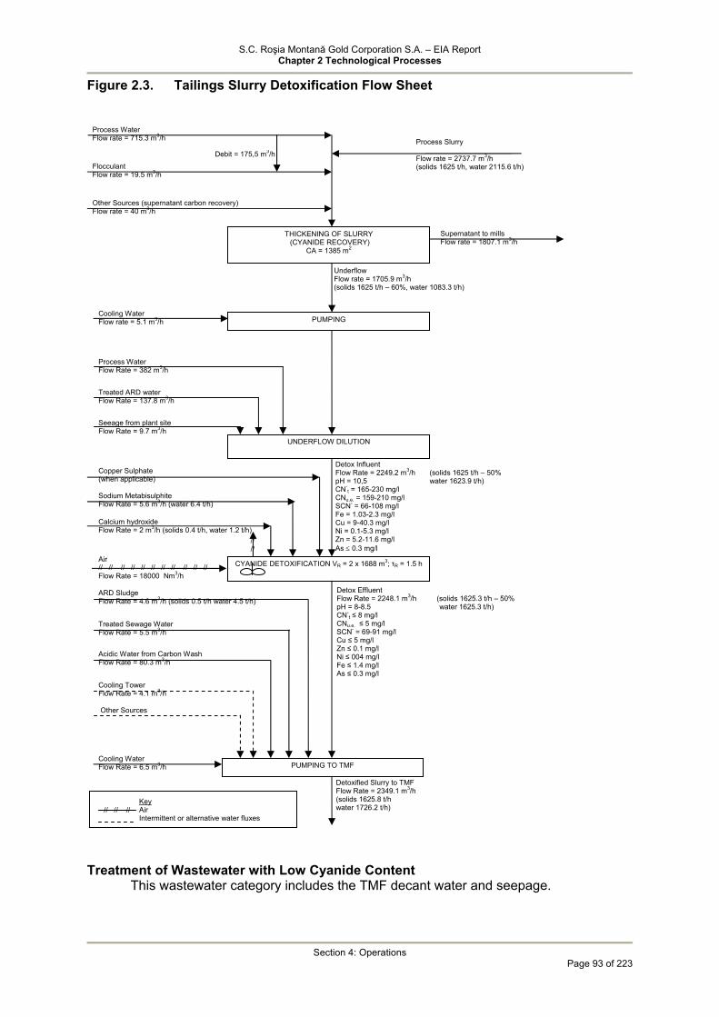
S.C. Roşia Montană Gold Corporation S.A. – EIA Report Chapter 2 Technological Processes
Section 4: Operations
Page 93 of 223
Figure 2.3. Tailings Slurry Detoxification Flow Sheet
Treatment of Wastewater with Low Cyanide Content This wastewater category includes the TMF decant water and seepage.
Calcium hydroxide Flow Rate = 2 m3/h (solids 0.4 t/h, water 1.2 t/h)
Process Water Flow rate = 715.3 m3/h
Flocculant Flow rate = 19.5 m3/h
Other Sources (supernatant carbon recovery) Flow rate = 40 m3/h
THICKENING OF SLURRY (CYANIDE RECOVERY)
CA = 1385 m2
Process Slurry Flow rate = 2737.7 m3/h (solids 1625 t/h, water 2115.6 t/h)
Debit = 175,5 m3/h
PUMPING
Underflow Flow rate = 1705.9 m3/h (solids 1625 t/h – 60%, water 1083.3 t/h)
Supernatant to mills Flow rate = 1807.1 m3/h
Cooling Water Flow rate = 5.1 m3/h
Process Water Flow Rate = 382 m3/h
Treated ARD water Flow Rate = 137.8 m3/h
Seeage from plant site Flow Rate = 9.7 m3/h
Copper Sulphate (when applicable)
Sodium Metabisulphite Flow Rate = 5.6 m3/h (water 6.4 t/h)
Air Flow Rate = 18000 Nm3/h
ARD Sludge Flow Rate = 4.6 m3/h (solids 0.5 t/h water 4.5 t/h)
Treated Sewage Water Flow Rate = 5.5 m3/h
Acidic Water from Carbon Wash Flow Rate = 80.3 m3/h
Cooling Tower Flow Rate = 4.1 m3/h
Other Sources
UNDERFLOW DILUTION
CYANIDE DETOXIFICATION VR = 2 x 1688 m3; τR = 1.5 h
Detox Influent Flow Rate = 2249.2 m3/h (solids 1625 t/h – 50% pH = 10,5 water 1623.9 t/h) CN-
t = 165-230 mg/l CNu.e. = 159-210 mg/l SCN- = 66-108 mg/l Fe = 1.03-2.3 mg/l Cu = 9-40.3 mg/l Ni = 0.1-5.3 mg/l Zn = 5.2-11.6 mg/l As ≤ 0.3 mg/l
// // // // // // // // // // //
PUMPING TO TMF
Detox Effluent Flow Rate = 2248.1 m3/h (solids 1625.3 t/h – 50% pH = 8-8.5 water 1625.3 t/h) CN-
t ≤ 8 mg/l CNu.e. ≤ 5 mg/l SCN- = 69-91 mg/l Cu ≤ 5 mg/l Zn ≤ 0.1 mg/l Ni ≤ 004 mg/l Fe ≤ 1.4 mg/l As ≤ 0.3 mg/l
Detoxified Slurry to TMF Flow Rate = 2349.1 m3/h (solids 1625.8 t/h water 1726.2 t/h) // // //
Key Air Intermittent or alternative water fluxes
// //
Cooling Water Flow Rate = 6.5 m3/h
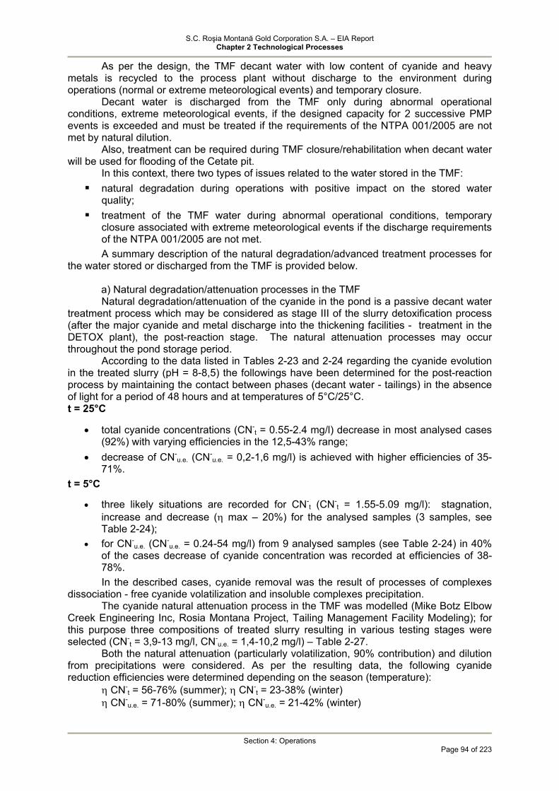
S.C. Roşia Montană Gold Corporation S.A. – EIA Report Chapter 2 Technological Processes
Section 4: Operations
Page 94 of 223
As per the design, the TMF decant water with low content of cyanide and heavy metals is recycled to the process plant without discharge to the environment during operations (normal or extreme meteorological events) and temporary closure.
Decant water is discharged from the TMF only during abnormal operational conditions, extreme meteorological events, if the designed capacity for 2 successive PMP events is exceeded and must be treated if the requirements of the NTPA 001/2005 are not met by natural dilution.
Also, treatment can be required during TMF closure/rehabilitation when decant water will be used for flooding of the Cetate pit.
In this context, there two types of issues related to the water stored in the TMF: natural degradation during operations with positive impact on the stored water
quality; treatment of the TMF water during abnormal operational conditions, temporary
closure associated with extreme meteorological events if the discharge requirements of the NTPA 001/2005 are not met. A summary description of the natural degradation/advanced treatment processes for
the water stored or discharged from the TMF is provided below. a) Natural degradation/attenuation processes in the TMF Natural degradation/attenuation of the cyanide in the pond is a passive decant water
treatment process which may be considered as stage III of the slurry detoxification process (after the major cyanide and metal discharge into the thickening facilities - treatment in the DETOX plant), the post-reaction stage. The natural attenuation processes may occur throughout the pond storage period.
According to the data listed in Tables 2-23 and 2-24 regarding the cyanide evolution in the treated slurry (pH = 8-8,5) the followings have been determined for the post-reaction process by maintaining the contact between phases (decant water - tailings) in the absence of light for a period of 48 hours and at temperatures of 5°C/25°C. t = 25°C
• total cyanide concentrations (CN-t = 0.55-2.4 mg/l) decrease in most analysed cases
(92%) with varying efficiencies in the 12,5-43% range; • decrease of CN-
u.e. (CN-u.e. = 0,2-1,6 mg/l) is achieved with higher efficiencies of 35-
71%. t = 5°C
• three likely situations are recorded for CN-t (CN-
t = 1.55-5.09 mg/l): stagnation, increase and decrease (η max – 20%) for the analysed samples (3 samples, see Table 2-24);
• for CN-u.e. (CN-
u.e. = 0.24-54 mg/l) from 9 analysed samples (see Table 2-24) in 40% of the cases decrease of cyanide concentration was recorded at efficiencies of 38-78%. In the described cases, cyanide removal was the result of processes of complexes
dissociation - free cyanide volatilization and insoluble complexes precipitation. The cyanide natural attenuation process in the TMF was modelled (Mike Botz Elbow
Creek Engineering Inc, Rosia Montana Project, Tailing Management Facility Modeling); for this purpose three compositions of treated slurry resulting in various testing stages were selected (CN-
t = 3,9-13 mg/l, CN-u.e. = 1,4-10,2 mg/l) – Table 2-27.
Both the natural attenuation (particularly volatilization, 90% contribution) and dilution from precipitations were considered. As per the resulting data, the following cyanide reduction efficiencies were determined depending on the season (temperature): η CN-
t = 56-76% (summer); η CN-t = 23-38% (winter)
η CN-u.e. = 71-80% (summer); η CN-
u.e. = 21-42% (winter)

S.C. Roşia Montană Gold Corporation S.A. – EIA Report Chapter 2 Technological Processes
Section 4: Operations
Page 95 of 223
It can be considered that by natural processes in the pond, the total cyanide and WAD cyanide concentrations are reduced under the influence of various factors including seasonal temperature variations. On average, a reduction of approximately 50% of the CN-
t in the pond during operations may be considered. According to the natural degradation/attenuation process model in the first three years after the mine closure a reduction to 0.1 mg CN-
t/L may be expected. b) Secondary Treatment Processes Practically, during normal operations there is no discharge of waste water with
cyanide content to the environment. The potential wastewater sources, decant water and TMF seepage (if any) have the following regime:
• Decant water: storage in the pond, recycling to the process plant; • Seepage: collected in the SCS sump and pumped back to the TMF pond.
Decant water is discharged from the TMF only during abnormal operational conditions, extreme meteorological events, if the designed capacity for 2 successive PMP events is exceeded and must be treated if the requirements of the NTPA 001/2005 are not met by natural dilution.
Residual cyanide in the decant water (and seepage) consists of stable cyanide complexes, mainly ferrocyanide and ferricyanide.
Three processes for the treatment of water containing low concentrations of cyanide on the order of mg/l total cyanide have been proposed through the amended design (MWH, Secondary Cyanide Treatment Methodology, March 2006) as follows:
• adsorption on activated carbon or a sorbent based on hydroxiapathit and elementary carbon resulting from dry bone distillation;
• reverse osmosis; • oxidation in the system of SO2/air and hydrogen peroxide.
All processes may be applied for water containing low concentrations of cyanide. The first two are cyanide removal processes by adsorption on a sorbent or
separation in a concentrate and the third is a cyanide destruction process and conversion into less toxic compounds.
In case of adsorption aspects related to sorbent regeneration or waste generation may be raised; from the Project’s point of view the used sorbent containing adsorbed cyanide is therefore a hazardous waste.
In case of reverse osmosis the concentrate containing cyanide together with other components separated from water constitutes hazardous waste entering the Project waste management circuit. In this case, by separation of other constituents a high quality treated water will result.
The first two processes are currently under development without industrial application. The cyanide oxidation processes from wastewater using various agents are applied at industrial scale and also in the mining sector.
The SO2/air or hydrogen peroxide processes are applied at industrial scale while other oxidation processes based on peroxides (Caro's acid, CombinOx etc.) are under development.
The BAT documents recommend for cyanide effluents from mining activities both the oxidation processes (INCO, hydrogen peroxide) and adsorption on carbon.
Given the imposed limit value of 0.1 mg CN-t/L, the MWH Study proposes the testing
at pilot scale during the Project construction of the three processes in order to determine the most efficient and cost effective method. Based on the pilot testing results, treatment facilities for wastewater containing low concentrations of cyanide will be constructed during operations.
According to the Project, such waste water will occur during operations (when the TMF decant water and seepage are recycled to the gold recovery process) only in abnormal conditions when at dilutions above two successive PMP events treatment is required to comply with the regulatory limits for water discharge to the environment.

S.C. Roşia Montană Gold Corporation S.A. – EIA Report Chapter 2 Technological Processes
Section 4: Operations
Page 96 of 223
Starting from year 13 of operations a passive/semi-passive treatment system (lagoons) will be commissioned for testing in view of subsequent improvement of the quality of the water discharged from the SCS sump during closure and post-closure.
If the testing results will not be as expected, the lagoons will become operational in the closure/post-closure phase. The water will be discharged from these lagoons into the Corna valley. If the NTPA 001/2005 requirements are not met, depending on the nature of the pollutants escaping the lagoon system, the water will be routed to the secondary treatment plant for water containing low concentrations of cyanide or to the ARD plant.
Table 2-28 summarises the slurry treatment/decant water advanced treatment alternatives during the different periods of mining activities carried out in the Roşia Montana area.

S.C. Roşia Montană Gold Corporation S.A. – EIA Report Chapter 2 Technological Processes
Section 4: Operations
Page 97 of 223
Table 2-27 Influence of dilution and natural attenuation processes on the cyanide concentration (CN-
t si CN-u.e.) in the TMF during operations (pH = 8-8.5)
Decant Water (TMF) No.
Treated Slurry (TMF discharge) Summer Winter
1 CN-t = 3.9 mg/l CN-
t = 1.5 mg/l CN-t = 3 mg/l
CN-u.e. = 1.4 mg/l CN-
u.e. = 0.8 mg/l CN-u.e. = 1.1 mg/l
2 CN-t = 8 mg/l CN-
t = 2 mg/l CN-t = 5 mg/l
CN-u.e. = 5.2 mg/l CN-
u.e. = 1.5 mg/l CN-u.e. = 3 mg/l
3 CN-t = 13 mg/l CN-
t = 3 mg/l CN-t = 8 mg/l
CN-u.e. = 10.2 mg/l CN-
u.e. = 2 mg/l CN-u.e. = 6 mg/l
Reference: Elbow Creek Engineering Inc/2004. Rosia Montana Tailing Management
Facility Modeling Memorandum. Prepared for MWH, July 2004
S.C. Roşia Montană Gold Corporation S.A. – EIA Report Chapter 2 Technological Processes
Section 4: Operations
Page 98 of 223
Table 2-28 Slurry / decant water treatment possibilities during operations - temporary closure - closure - post-closure No. Project Phase Slurry Circuit Decant Water Circuit
Process plant – DETOX plant – TMF Recycling to the process plant (no cyanide containing water is discharged into the emissary)
1
Operations (1-16 years) Normal operating conditions, dry weather /precipitations, including extreme meteorological events (2xPMP) or temporary closure
Slurry composition at TMF entrance pH = 8-8.5 CN-
u.e. < 10 mg/l
Decant water composition pH ≤ 8 CN-
u.e. ≤ 5 mg/l CN-
t = 2-7 mg/l
2
Mine + process plant closure Post-closure Flooding of Cetate Pit
-
a) TMF → Cetate pit (if CN-t < 0.1 mg/l)
b) TMF → emissary ( if CN-t < 0.1 mg/l)
c) TMF → secondary cyanide detoxification plant → Cetate pit/emissary (if CN-
t > 0,1 mg/l)
NOTE: The automation elements in th PIE (ORP and CN control) are not presented in the basic design - AUSENCO or in the automation diagram (Tailings
Thickening and Detoxification Sheet 2 of 2 Piping and Instrumentation Diagram No. 1418-31-P-2313).

S.C. Roşia Montană Gold Corporation S.A. – EIA Report Chapter 2 Technological Processes
Section 4: Operations
Page 99 of 223
4.1.3.3 ARD Treatment Section 2.3.3 comprised a summary description of the processes used for ARD water
treatment, including the process proposed for the Project for the treatment of the Roşia Montană ARD water.
The ARD related issues are as follows: treatment processes: principles, performance at industrial scale, restraints; application within the Roşia Montană Project: water sources, characteristics, process
parameters, performance, limits with respect to environmental requirements, technical solutions. As shown above, the ARD water treatment processes can be active (generally,
chemical neutralization processes, oxidation, precipitation and separation of solids), passive/semi-passive conducted in more or less arranged facilities having similar purpose to the active processes, and combined processes. Active ARD Treatment Technologies
Active ARD treatment technologies are based on a series of common operations that aim to improve ARD water quality and treat the solid phase resulted by precipitation (metal hydroxides, carbonates, carbohydrates, calcium sulphate).
Neutralisation/precipitation: ensures acidity reduction and rapid precipitation of metals as hydroxides in one or two stages, depending on the water composition.
Neutralisation reagents: • calcium hydroxide (the most used, it is also coagulation-flocculation reagent,
removes sulphate down to the solubility level – CaSO4) – recommended as BAT; • sodium hydroxide (caustic soda is recommended in case of low ARD flow rates,
in isolated locations and for water with high concentration of manganese; sulphates remain in soluble phase – recommended as BAT;
• sodium carbonate: is recommended in case of low flow rates, precipitates existing calcium, does not precipitate sulphates – recommended as BAT;
• slaked lime / CO2: removes sulphates to the calcium sulphate solubility limit however the reaction rate is relatively small and the process is difficult to control in case of variations in ARD composition;
• milk of lime / CO2: wide applicability range, robust technology used frequently for ARD water, removes sulphates to the calcium sulphate solubility limit, has the disadvantage of generating large amounts of sludge compared to the use of quicklime (CaO) alkalization;
• limestone, dolomite: removes sulphates to the calcium sulphate solubility limit however the reaction rate is relatively small and does not ensure advanced precipitation of heavy metals (Cd, Mn, etc) - recommended as BAT
• thermal plant slag/red sludge from alumina production (potentially reusable waste) may generate additional pollution, acts differentially on sulphates;
The following can also be used as neutralisation and/or precipitation reagents: magnesium hydrate, ammonia (especially for water containing iron and manganese generating impact to environment and having limited applicability in the mining industry), sulphide (especially for water containing zinc and lead).
Sludge (Precipitate) Separation: lamellar or plane settling tanks with or without addition of flocculant are used; the “high density sludge” technology ensures increase of solids from 5% up to 25-30% and is based on recycling a portion of the sludge at the settling tank entry. ARD Passive Treatment Technologies
In the context of ARD, the term "passive treatment system” refers to a a wastewater treatment system that uses naturally available energy sources such as: topographical
S.C. Roşia Montană Gold Corporation S.A. – EIA Report Chapter 2 Technological Processes
Section 4: Operations
Page 100 of 223
gradient, microbial metabolic energy, photosynthesis and chemical energy. It requires only infrequent (albeit regular) maintenance to operate succesfully over its design life.
The main ARD passive treatment processes are the following: • specially built/developed lagoons: use the bio potential of the soil and
seepage water associated with the bio potential of the plants which retain/treat acidic contaminants and heavy metals. The mechanisms involve aerobic/anaerobic, ion exchange, adsorption, hydroxides, sulphates precipitation processes. The solid lagoon layers retain precipitates and purify water. It uses not so much soil but more agricultural, animal waste, compost to construct the lagoons. Unlike the chemical systems, the passive systems require high capital costs (land development, tanks, equipment) but the operating costs are minimal. The industrial experience in this field is not long therefore the optimum sizing and configuration of the lagoons is still an empiric process. It is recommended that the existing (natural) lagoons within the mining areas are not destroyed because it would expose new rocks to oxidation processes. The applicability of the lagoon systems involves small water flow rates (in the order of tens of l/min). The long-term impact of these lagoons is not fully known and it may be possible that the treatment efficiency decreases in time depending also on the season – BAT reference.
• settling ponds, open channels or limestone drains: are easy to construct by filling or lining ponds/channels with limestone. Dissolution in time of limestone leads to increased alkalinity and pH. Limestone must be replaced periodically because it gets used up in time and the deposition of iron and aluminium precipitates reduces the neutralisation efficiency (an agitation system may be fitted to avoid limestone clogging) – BAT reference.
• modified shafts - recommended as BAT. The passive treatment technologies represent a long-term solution after closure of mining operations but they require a polishing step and preventative measures. Combined ARD Treatment Technologies
Multi-stage treatment (e.g. pilot-scale plant constructed in UK at the Wheal Jane – Cornwell mine, the largest such plant in Europe) where treatment occurs in three treatment systems, as follows:
• Aerobic reed beds (remove metal hydroxides and arsenic); • Anaerobic cell (mixture of manure, straw or wood sawdust for anaerobic
conditions) for bacterial sulphate reduction with simultaneous release of metals i.e. zinc, cadmium, copper, iron;
• Aerobic rock filters with algae stimulation/development (removal of manganese). Each of the three systems includes a specific pre-treatment stage to increase the pH
with lime or limestone. The above mentioned procedures assume the removal of calcium and sulphate,
which are typical polluting constituents in mining areas. Generally, the licenses regarding ARD treatment plants refer to pH increase and
heavy metal precipitation rather than removal of calcium and sulphate. The table below shows data from the mines in USA and Canada regarding the
efficiency achieved for sulphate removal and the thesholds for the quality of treated effluents. Table 2-29 Concentrations of sulphates achieved through certain ARD treatment
plants Plant Quality of treatment
plant effluent (mg/l) Effluent Thresholds mg/l)
Applicable Water Quality Standard (mg/l))

S.C. Roşia Montană Gold Corporation S.A. – EIA Report Chapter 2 Technological Processes
Section 4: Operations
Page 101 of 223
Eagle Mine, USA 2750 3600 250 Urad Mine, USA No data No threshold 250 ARD Canada 3300 4500 100 Yak Tunnel, USA 460 No threshold 250 (process water) Campbell Mine, Canada No data available No threshold 500 (drinking water) Argo Tunnel, USA No data available No threshold 250 Porgera Mine PNG No data available) No threshold Not available
Table 2-30 shows the results regarding the calcium and sulphate concentrations in effluents at various types of plants, including for ARD treatment. Table 2-30. Calcium and sulphate concentrations in water discharged from various
neutralisation plants – lime precipitation Plant Treatment Method Ca (mg/l) SO4
2- (mg/l) Waihi Gold (New Zeeland) Lime neutralization of
effluent 120 - 160* 200 - 700*
Britannia Mine, Canada Lime neutralisation of ARD
400 2200
Copper Refinery (Australia) Lime neutralisation 410 1350 Copper Smelter (Australia) Lime neutralization of
local effluent 490 (predicted) 5000
*the compliance limits were determined based on a dilution factor As outlined above, the efficiencies are typical when using lime as neutralisation-
precipitation agent and are dependant on the calcium sulphate solubility. The limits required for the quality of the resulting effluents are in compliance with this technical restriction.
There are many ARD treatment methods known, namely: inverse osmosis, electrodialysis, electrolysis, ion exchange, active carbon adsorption, evaporation/distillation/crystallisation. Except for carbon adsorption, all other methods yield very good efficiencies however they involve high costs and are applied in a limited degree, correlated with water composition and flow rates and quality required for treated water.
Advanced removal of dissolved salts is achieved through these methods with full removal being possible in some cases.
Such quality is not required for ARD water. The baseline contamination specific for mining areas indicates the presence of
calcium in concentrations of hundreds of mg/l (for example in the Rosia Montana area concentrations are up to 350-400 mg/l) while in the ARD water sulphate may reach thousands of mg/l depending on the nature of the rocks.
The concentrations for release to environment are laid down in NTPA 001/2005 at 300 mg/l for calcium (below the Rosia Montana baseline concentrations)
The methods most often applied in the mining industry are based on sulphate precipitation and remove these ions to the calcium sulphate solubility limit (about 2 g/l). Specialist studies regarding calcium sulphate toxicity for aquatic organisms (fish, Daphni, algae) indicate that this compound has low toxicity and is tolerated in relatively high concentrations, as shown below:
fish CL50 (96 hours) - 2,980 mg/l Final Report nr. RG3965 (C2R1), US Academy of Natural Sciencies, Public Health Service Grant, Philadelphia; Patrick R.J., Scheier A., Prog Fish-Cult, 30(3); 137-140, 1968
• Daphnia CL50 (24 hours) > 1,970 mg/l Final Report nr. RG3965 (C2R1), US Academy of Natural Sciencies, Public Health Service Grant, Philadelphia;
• Algae CL50 (96 hours) - 3,200 mg/l Final Report nr. RG3965 (C2R1), US Academy of Natural Sciencies, Public Health Service Grant, Philadelphia;
• algae NR 30 days – 1,872 mg/l, (Becker AJ.J, Proc.W.Va.Acad.Sci., 45(2) ; 127- 135, 1973.
Processes are developed and applied that ensure advanced removal of calcium and sulphate ions below the calcium sulphate solubility limit, namely:

S.C. Roşia Montană Gold Corporation S.A. – EIA Report Chapter 2 Technological Processes
Section 4: Operations
Page 102 of 223
Walhalla Process – precipitation of sulphate and calcium ions as Ettringite (3CaO⋅3CaSO4⋅Al2O3⋅31H2O) which is stable at pH = 12 (large volumes of precipitate);
Thio Paques Process – bio-desulphurisation in anaerobic reactors. This process is difficult to control at large temperature variations (does not remove calcium ions);
Gyp Cix Process – combined precipitation and ion exchange process; BaSO4 Precipitation – using BaCl2 (secondary chloride contamination ) or BaCO3.
This process is efficient but costly at large flow rates; Inverse osmosis – membrane process that ensures advanced removal of all water
soluble salts (quality comparable to that of drinking water) with reduced applicability for ARD water (problems: membrane clogging, sludge disposal).
The above processes are not used in the mining industry unless where restrictions on the quality of released effluents are imposed. ARD and Metal and Sulphate Bearing Water Treatment – Roşia Montana's case ARD Sources
The Project ARD generation sources are generally associated with historical mining operations; a new wastewater treatment plant will be constructed for the ARD and metal bearing water.
The primary categories of ARD water treated through the treatment plant are the following:
• ARD runoff water from the previous mining operations within the Project area (mine galleries, existing waste rock stockpiles, RosiaMin open pits);
• water from the future open pit sites; • Project site runoff water; • Water from the low-grade ore stockpile; • Water from the waste rock stockpiles – Cetate and Cirnic. Diversion works will be constructed to direct clean water downstream of the Project
area. Potential ARD runoff will be collected in two catchment ponds, the Cetate waste and
mine drainage pond and the Cîrnic waste rock and mine drainage pond and pumped to the ARD treatment plant.
Water collected in the Cîrnic Waste Rock Drainage Pond can be released to the TMF for reuse in the ore process if the water quality is suitable without treatment.
• the Project will include installation of a valved plug in the 714 adit, which allows for:
• controlled release of water in the underground mine workings; • prevent water impounded behind the Cetate Dam from backing up into the open-
pits when these are developed below the 714-adit level. Treated effluent will be used after the first treatment stage in the process for various
purposes and the final effluent will be used for environmental base flows in Rosia and Corna streams. The sludge will be disposed in the TMF. Exhibit 2.5. presents the diagram for the ARD water treatment plant inflows and outflows.
Currently, the surface runoff within the existing mine site from adits, waste rock stockpiles, open pits is characterised by low pH and heavy metal (Cu, Fe, Mn, Ni, Zn) concentrations that exceed permissible levels.
Based on laboratory Acid Base Accounting (ABA) and kinetic tests, quality of the composite runoff and seepage from the planned new waste rock disposal sites is expected to be neutral and low in dissolved metals, during the initial years of operation.

S.C. Roşia Montană Gold Corporation S.A. – EIA Report Chapter 2 Technological Processes
Section 4: Operations
Page 103 of 223
Figure 2.4 Diagram for the ARD water treatment plant inflows and outflows
However, given the heterogenous nature of the waste rocks, under external factors (oxygen, rainfall) the potential for ARD generation may occur. In this context, all above mentioned ARD water sources will be adequately collected, monitored and directed for treatment through the ARD treatment plant or reuse. The ARD water flow rate estimated for the operations is 400-600 m3/h. Description of Treatment Processes
The selection of the treatment process of ARD water with metal (Cu, Zn, Mn, Fe, Ca, Al) concentrations ranging from mg/l to hundreds of mg/l and sulphate concentrations in the order of g/l that is based on two pH adjustment stages, metal/sulphate precipitation to solubility limits (stage 1 – lime, stage 2 – CO2) and intermediate segregation of the precipitated phase, is supported by the following:
• its widespread application for ARD treatment at numerous mines worldwide and its acceptance as active BAT;
• laboratory/pilot test results obtained on real and synthetic wastewater covering the variability of present and future physical and chemical characteristics for the Rosia Montana Project site;
• the maximum discharge flow rate (Q ≥ 400 m3/h) which precludes the application of passive processes;
• the condition for the final effluent to meet the quality requirements layed down by NTPA-001/2005 at discharge into natural receivers;
Cetate Waste Rock Site
Open Pit Run off via 714 Adit
Old Mine Waste run- off
Run off from the
Project Area
Low Grade Ore Stockpile
Carnic Waste Rock
SitCarnic Waste
Drainage Pond
Wastewater Treatment Plant
Process Water Tank
Corna Valley Rosia Valley
P = precipitation E = evaporation
P E
TMF
P E
Cetate Water
Catchment
Sludge
S.C. Roşia Montană Gold Corporation S.A. – EIA Report Chapter 2 Technological Processes
Section 4: Operations
Page 104 of 223
• the technological implications, the capital and operational costs in industrial scale applications.
The technical specifications regarding the ARD physical and chemical characteristics
and the preferred treatment solution are presented in the "ARD Treatment Plant Report” (Ausenco 2004).
The following activities have been carried out in order to develop the ARD treatment technology:
• ARD sampling and description in Cetate (including the 714 Adit) and Cârnic (seepage from old waste rock stockpiles) areas;
• preparation/description of artificial ARD samples considered as representative for the majority of ARD mining sources;
• pilot laboratory testing for establishing the optimal treatment flow rate (treatment phase sequences, operational parameters, reagent consumptions).
Table 2-31 presents the following ARD water quality ranges:
• pH – strong acid character (pH <3); • variable concentrations of heavy metals, in excess of the permissible limits (Cd ≤
0,4 mg/l, Cu ≤ 2,4 mg/l, Zn ≤ 53 mg/l, Mn ≤ 350 mg/l, Fetot ≤ 49 mg/l); • elevated concentrations of sulphate in the order of g/l (SO4
2- ≤ 4.6 g/l), calcium and aluminium ions in the order of tens – hundreds of mg/l (Ca2+ ≤ 354 mg/l, Al ≤ 291 mg/l); calcium concentration may exceed the NTPA 001/2005 level of 300 mg/l .
As concerns the Fet mode of presentation, in view of the ARD generation mechanisms, it would be highly probable for iron to exist in its divalent form - Fe2+. However, the large time interval between sampling and analysis (November 2003 – December 2003) has precluded the identification of Fe2+. As a consequence, this aspect has been considered only after completing the experimental tests. It should be noted that the introduction of aeration after precipitation does not influence the overall efficiency of the process and the quality of the final effluent.
The experimental tests were carried out using two wastewater categories: • ARD from the 714 Adit – Cetate (considered as the worst case scenario); • synthetic ARD with relatively moderate concentrations of contaminants, considered
as representative for the ARD treatment plan influent. • The following aspects have been addressed by the experiments: • identifying the optimal pH for precipitation/co-precipitation of heavy metals (Cu, Zn,
Mn, Fe, Cd) and sulphates (down to the solubility limits), by using a suspension of hydrated lime (CaO = 60 %), as alkalinisation agent with pH = 9.7 – 10 (11);
• identifying the optimal conditions for solid/liquid separation and for advanced reduction of suspended solids in the supernatant (flocculant amount, clarification time, superficial loading) as well as the sludge volume;
• evaluating the carbon dioxide consumption for pH readjustment to the permitted range (pH = 8-8.5) and the removal of soluble Al, in strong alkaline pH;
• assessing the possibilities to reuse the precipitate separated at the settling phase in order to accelerate the precipitation of calcium sulphate and to improve the quality of the sludge.
The pilot tests results (Tables 2-32, 2-33, 2-34) were used as a database for
developing the ARD treatment flowsheet including the following main phases: Phase I air oxidation /lime precipitation - clarification (pH = 9.7-11)

S.C. Roşia Montană Gold Corporation S.A. – EIA Report Chapter 2 Technological Processes
Section 4: Operations
Page 105 of 223
Phase II pH readjustment with CO2 (pH = 8.5) and segregation of suspended solids.
The process ensures that the majority of the contaminants exceeding the permissible levels are removed, as follows:
Phase I • advanced precipitation (> 98 % efficient) of heavy metals (Cu, Mn, Fe, Zn, Cd),
with soluble residues below the NTPA 001/05 limits; • precipitation primarily of Al (η = 94%) and partially of sulphates (η = 55%) to the
solubility limit of the newly formed calcium sulphate. Phase II • optimal pH allowed for discharge; • precipitation of complexed aluminium until the concentration of soluble residues
falls below the discharge limit. Approximately 35 % of the decant water volume from phase I will be used as process
water in the processing plant and in the detoxification plant. The underflow sludge (phase I) is partially recycled to lime neutralisation, in order to
enhance the precipitation of heavy metals and calcium sulphate and to improve the quality of the sludge (~ 10 % solids) which is discharged to TMF.
The sludge compositions from the two phases (phase I – lime treatment, phase II – CO2 treatment) are different (Table 4.29). Thus, the sludge from the lime precipitation process contains metal hydroxides, calcium sulphate (gypsum) and lime tailings ((Al ≤ 5%, Ca ≤ 15%, Fe ≤ 12%, Mn ≤ 9,6%, Zn ≤ 1,4%, SO4
2- ≤ 28%), whereas the sludge from phase II is formed of sulphate, calcium carbonate and aluminium hydroxide, respectively ((Al ≤ 10%, Ca ≤ 17%, SO4
2- ≤ 36%, CO32- = 2%). In order to further remove the suspended solids
from the final effluent (approx. 171 mg/l), a final flocculation-clarification stage is required to meet the limits provisioned by the NTPA001 standard (<35 mg/l).
Under these conditions, the final effluent meets to a great extent the regulatory standards provided for effluents discharged to environment (pH, heavy metals and Al) except for sulphate, calcium, fixed residue and will be used to maintain base flows in the Rosia and Corna streams; sludge is disposed to the TMF.
The reactions occurring in the ARD treatment process are mainly acidity neutralisation/ hydroxides and sulphates precipitation.
In the case of ferrous ion (which precipitates as hydroxide only at pH = 11) simultaneous aeration and neutralisation are recommended in order to oxidise Fe2+ to Fe3+ and to precipitate the ferric hydroxide.
When the pH shifts towards alkaline conditions (pH min. = 9.7; pH max = 11), conditions are met to precipitate manganese in the form of hydroxide.
The basic reactions are the following: 4FeSO4 + O2 + 4Ca(OH)2 → 4Fe2(SO4)3 + 4CaSO4 (oxidation) (1) CuSO4 + Ca(OH)2 → Cu(OH)2 + CaSO4* (2) Fe2 (SO4 )3 + 3Ca(OH)2 + 1½ O2 → 2Fe(OH)3 + 3CaSO4* (3) MnSO4 + Ca(OH)2 → Mn(OH)2 + CaSO4* (4) NiSO4 + Ca(OH)2 → Ni(OH)2 + CaSO4* (5) ZnSO4 + Ca(OH)2 → Zn(OH)2 +CaSO4* (6) ** ignoring hydration effects
Calcium ions added with the lime slurry combine with sulphate ions to form aqueous calcium sulphate, and the quantity that exceeds the solubility level precipitates as solid calcium sulphate (equation 7). CaSO4 (aq) + 2H2O → CaSO4 ·2H2O(s) above solubility limit of CaSO4 (7)
(aq = aqueous, s = solid) The unreacted lime is partially dissolved based on its solubility (equation 8)
Ca(OH)2 (s) → Ca(OH)2 (aq) (to solubility limit) (8)

S.C. Roşia Montană Gold Corporation S.A. – EIA Report Chapter 2 Technological Processes
Section 4: Operations
Page 106 of 223
The treated effluent with a pH of about 11 can be directly reclaimed as process water. The effluent to be discharged to surface water is treated with gaseous carbon dioxide, which, depending on the pH value, reacts first with the excess of slaked lime (pH > 8.3) and secondly with the resulting calcium carbonate (pH< 8.3) (equations 9 and 10). Ca(OH)2 + CO2 → CaCO3 + H2O (9) CaCO3 + CO2 + H2O → Ca2+ + 2HCO3
- (10) The residual concentrations of calcium sulphate and implicitly of dissolved salts (fixed residue) meet the solubility limit of the compound.
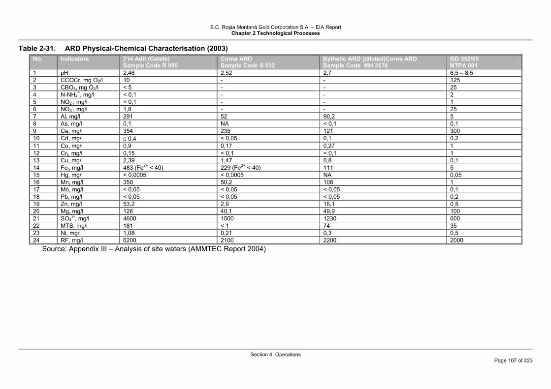
S.C. Roşia Montană Gold Corporation S.A. – EIA Report Chapter 2 Technological Processes
Section 4: Operations
Page 107 of 223
Table 2-31. ARD Physical-Chemical Characterisation (2003) No. Indicators 714 Adit (Cetate)
Sample Code R 085 Corna ARD Sample Code S 032
Sythetic ARD (diluted)Corna ARD Sample Code MH 3576
GD 352/05 NTPA 001
1 pH 2,46 2,52 2,7 6,5 – 8,5 2 CCOCr, mg O2/l 10 - - 125 3 CBO5, mg O2/l < 5 - - 25 4 N-NH4
+, mg/l < 0,1 - - 2 5 NO2
-, mg/l < 0,1 - - 1 6 NO3
-, mg/l 1,8 - - 25 7 Al, mg/l 291 52 90,2 5 8 As, mg/l 0,1 NA < 0,1 0,1 9 Ca, mg/l 354 235 121 300 10 Cd, mg/l ≤ 0,4 < 0,05 0,1 0,2 11 Co, mg/l 0,9 0,17 0,27 1 12 Crt, mg/l 0,15 < 0,1 < 0,1 1 13 Cu, mg/l 2,39 1,47 0,8 0,1 14 Fet, mg/l 483 (Fe2+ < 40) 229 (Fe2+ < 40) 111 5 15 Hg, mg/l < 0,0005 < 0,0005 NA 0,05 16 Mn, mg/l 350 50,2 108 1 17 Mo, mg/l < 0,05 < 0,05 < 0,05 0,1 18 Pb, mg/l < 0,05 < 0,05 < 0,05 0,2 19 Zn, mg/l 53,2 2,9 16,1 0,5 20 Mg, mg/l 126 40,1 49,9 100 21 SO4
2-, mg/l 4600 1500 1230 600 22 MTS, mg/l 181 < 1 74 35 23 Ni, mg/l 1,08 0,21 0,3 0,5 24 RF, mg/l 6200 2100 2200 2000
Source: Appendix III – Analysis of site waters (AMMTEC Report 2004)

S.C. Roşia Montană Gold Corporation S.A. – EIA Report Chapter 2 Technological Processes
Section 4: Operations
Page 108 of 223
Table 2-32 Physical-chemical characterisation per treatment stages (influent – ARD 714 adit) Limit Value No. Indicator I ED � % EF η %
Notes: 1 pH 2.38 9.7 - 8.49 - 2 Ca (mg/l) 2.45 < 0.05 98 - - 3 Fe, mg/l 415 < 0.05 > 99.9 - - 4 Mn, mg/l 360 < 0.05 > 99.9 0.07 - 5 Zn, mg/l 49.9 < 0.02 > 99.9 - - 6 Cd, mg/l 0.4 < 0.05 87.15 - 7 Ca, mg/l 350 1085 - 1000 ηf = 8
8 Al, mg/l 291 15.8 94.6 1.8 ηf = 88.6 9 Mg, mg/l 123 3.05 97.5 2.25 ηf = 26 10 MTS, mg/l 181 171 - 11 SO4
2-, mg/l 4600 2050 55.4 2530 -
Abbreviations/Notes: I = influent ARD 714 adit ED = effluent per precipitation/flocculation-clarification (pH = 9.7 EF = final effluent after neutralisation of CO2 (pH = 8.5). Note 1 – remaining metals and sulphate were analysed as soluble phase Note 2 – reagent consumptions: Lime (60% CaO) = 3.82 g/l PEA (anionic polyelectrolyte) = 2 mg/l CO2 = 42.8 g/l

S.C. Roşia Montană Gold Corporation S.A. – EIA Report Chapter 2 Technological Processes
Section 4: Operations
Page 109 of 223
Table 2-33. Variation of Mn concentration vs. pH (NTPA 001 – Mn = 1 mg/l) pH = 2.5 Mn = 360 mg/l
pH = 8.37 Mn = 42 mg/l (η = 88%) pH = 9.2 Mn = 2 mg/l (η = 99.4%) pH = 9.7 Mn < 0.5 mg/l (η ≥ 99.9%)
Note: Zn, Fe, Cu residues in the soluble phase are below regulatory limits (Cr < 0.05 mg/l), starting from pH = 8.37 to at least pH = 9.7 Table 2-34. Variation of Al concentration vs. pH (NTPA 001 – Al = 5 mg/l) pH = 2.5 Al = 291 mg/l pH = 9.7 (lime) Al = 15.8 mg/l (η = 94.6%) pH = 8.5 (CO2) Al = 1.8 mg/l (η = 99.4%) Note: the optimal pH for Al precipitation as hydrated oxide is 6.5 – 7.5; in alkaline conditions, the partial solubilisation of aluminium as [Al(OH)4]- occurs; the aluminate precipitates in the final phase of pH readjustment with CO2.

S.C. Roşia Montană Gold Corporation S.A. – EIA Report Chapter 2 Technological Processes
Section 4: Operations
Page 110 of 223
Table 2-35. Physical-chemical characterisation of effluents per treatment phases (influent – synthetic ARD) Limit Value Indicators IS ED η% EF η%
Notes:
pH 2.5 9.54 / 10,.6 8.45 − Cu, mg/l 0.8 < 0.02 > 75 - − Fe, mg/l 111 < 0.1 > 99 - − Mn, mg/l 108 0.42 / 0.33 99.9 0.35 − Zn, mg/l 16.1 < 0.02 > 99.9 - − Cd, mg/l 0.1 < 0.05 50 − Ca, mg/l 121 655 / 556 − 455 30 / 18 Al, mg/l 90.2 4.25 / 9.5 95/89 < 0.2 > 95 / 98 Mg, mg/l 49.9 1.8 96 - − MTS, mg/l 74 NA − NA − SO4
2-, mg/l 1230 1282 − 1455 − RF, mg/l 2200 NA − 2100 −
Abbreviations/Notes: IS – synthetic/diluted ARD ED – effluent per precipitation/flocculation-clarification (pH = 9,54/10,6) Note 1 – Heavy metals were analyzed in the soluble phase. Note 2 Reagent consumptions: Lime (60%CaO) = 1,02-1,2 mg/l
APE (anionic polyelectrolyte) = 2 mg/l CO2 = 42.8 g/l
Table 2-36. Characterisation of process chemical sludge
N1 (Adit 714) N2 synthetic water Indicator % (dry substance)
PFD NCO2 PFD Al % 3.99 9.8 5.2 Ca % 15 16.65 2.67 Fe % 6.2 - 12.4 Mg % 2.9 - 4.52 Mn % 4.81 - 9.55 Zn % 0.65 - 1.35 Sulphate % 27.9 36.2 4.24 Carbonate % - 2.1 - Calcination Losses % 16.6 - 22
Note: PFD – stage I sludge—(precipitation/flocculation-clarification) NCO2 – stage II sludge – (pH adjustment using CO2/clarification)

S.C. Roşia Montană Gold Corporation S.A. - Raport la studiul de evaluare a impactului asupra mediului Capitol 2 Procese tehnologice
Secţiunea 4: Faza de operare
Pagina 111 din 223
Description of the ARD Treatment Plant RD (acidic and with metals content) are treated especially for pH adjustment and
heavy metals precipitation. Treated water will be reclaimed for use in the process plant and discharged in Rosia and Corna streams to maintain enironmental baseflows.
ARD treatment process includes the following phases: • two stage pH adjustment and metals precipitation (with lime and carbon dioxide,
respectively) in conjunction with the oxidation of metals in reduced oxidation form (Fe2+, Mn2+);
• segregation of resulting precipitates by flocculation/clarification. Exhibit 2.5 presents the main stages/operations of the treatment processes as well
as the compositions for the main aqueous sytems and sludged disposed in the TMF. The plant capacity of 400 m3/hr has been designed for the first seven years of site
operation with the option for upgrading for additional capacity, if needed in the future The pH adjustment, oxidation and precipitation processes occurs in a series of 3
reactors identical in terms of useful volume, fitted with continuous mixing system. Slaked lime will be added to the feed solution of a continuously stirred tank reactor to
raise the pH to about 7.2. In addition, air will be added to the reactor tank to oxidize ferrous iron to ferric iron, which will then precipitate as ferric hydroxide . Flow from the neutralisation reactor will cascade to the second reactor where slacked lime is added to raise the pH to about 11. At elevated pH levels and oxidizing conditions, iron and other heavy metals such as copper, manganese, nickel, and zinc, will precipitate as hydroxides.
Calcium sulphate will precipitate as gypsum in the quantity that exceeds the solubility in water. Suspended solids in the oxidation/ precipitation reactor will consist of metal hydroxides, calcium sulphate minerals (e.g. gypsum) and some unreacted lime.
Following the neutralisation and oxidation /precipitation steps, the solution will be discharged by gravity to the clarifier for solids-liquid separation. A flocculant will be added to the clarifier feed tank to improve the settling characteristics of the solids. Clarifier underflow solids will be partially recirculated to the neutralization header to improve the precipitation of calcium sulphate, minimise scaling and improve the quality of the precipitate, which will be pumped as slurry to the tailings pump box where it will be pumped to TMF.
Some of the supernatant is pumped to the cyanide detoxification plant for thickener underflow dilution and other process needs (it is not recommended to use decant water in the preparation of flocculant solution, which requires fresh water. The remaining supernatant volume will flow by gravity to the carbon dioxide sparging process that will raise pH to 8.5
After mixing with flocculant, effluent from this phase will flow by gravity to the second clarification stage to reduce solids below the discharge limit (35 mg/l).
ARD sludge is pumped to the tailings pump box at the detoxification plant and to TMF. The supernatant flows by gravity to Rosia Valley with the excess volume being pumped to Corna Valley to maintain environmental baseflow. Any likely shortage during dry season will be compensated with fresh water from the Aries river. Process Automation
The ARD treatment plant will be equipped with the following automated controls: • automatic addition of slaked lime and pH control in the neutralisation/precipitation
and oxidation reactors; • automatic flow control of recycled sludge and sludge pumped to the tailings pump
box and TMF, depending on its density; • automatic addition of carbon dioxide and pH control in the neutralization
reactors; • automatic flow control of treated water pumped to Corna valley to maintain base
flow. • automatic flow control of fresh water used to maintain base flow.

S.C. Roşia Montană Gold Corporation S.A. - Raport la studiul de evaluare a impactului asupra mediului Capitol 2 Procese tehnologice
Secţiunea 4: Faza de operare
Pagina 112 din 223
As shown before: • the designed process ensures that the regulatory standards regarding the treated
ARD water quality is met expect for sulphate, calcium and fixed residue; • up to the calcium sulphate solubility limit, the eco-toxicological studies indicate
low toxicity to aquatic organisms (fish, Daphnia, algae); • The regulatory limits of the NTPA 001/2005 for calcium and sulphate are below
the concentrations achieved as a result of the designed precipitation process. Consequently, the Project also looked at other processes applicable at commercial
scale for advanced treatment of ARD water that will ensure the quality parameters laid down by NTPA 001/2005 are met.
Thus, the following processes were considered: • inverse osmosis or similar membrane technology as primary water treatment,
which would essentially replace the proposed neutralisation/precipitation process. • maintain the proposed process and complement it with specific phases (inverse
osmosis or precipitation as Ettringite) to remove calcium, sulphate and fixed residue.
• Chapter 5 – Alternatives presents a comparative analysis of the technological implications and costs for these alternatives.
Although pilot test are recommended for the selection of the optimal alternative, the conclusion is reached that from an environmental and technical implications standpoint this is the most suitable process for the Rosia Montana Project ARD quality and flow rates, namely:
• maintain the first pH adjustment and lime precipitation of metals step from the conventional ARD treatment process (final pH 11.5);
• precipitation of calcium and sulphate from the calcium sulphate solubile in presence of calcium aluminate cement (SX-44) in form of Ettringite Ca6Al2 (SO4)3(OH)12 26H2O;
• Process takes place in a mixing tank at pH = 11.5, retention time 30 – 60 min. • clarification of solids through the plant designed for the initially proposed process; • pH adjustment to 8.5 with carbon dioxide and precipitation of calcium carbonate,
aluminium hydroxide and small amounts of Ettringite; • removal of precipitates resulting from a final clarification step through a lamellar
settling tank. Treated water resulting from the two clarification steps maintains the destinations
included in the initial design. The process is easy to design and operate. Optimal retention time and reagent
additions may be selected in order to meet the regulatory requirements for calcium and sulphate concentrations at minimum capital and reagent costs.
Resulting precipitates are easy to dehydrate and will be directed, as described above, to the TMF.
At European level, this application of the Ettringite precipitation process is used at industrial scale, which warrants for the performance and operation of the process.
Thus complemented, it may be considered that the process proposed by the Rosia Montana Project meets all requirements regarding the quality of the ARD water treated and discharged by the process.

S.C. Roşia Montană Gold Corporation S.A. - Raport la studiul de evaluare a impactului asupra mediului Capitol 2 Procese tehnologice
Secţiunea 4: Faza de operare
Pagina 113 din 223
Figure 2-5: Acid Rock Drainage Treatment
F.rate= 156,3 m3/h
Cooling water Flow rate = 6,2 m3/h
Supernatant Fl. rate=440.9 m3/h (Water=440.9 tons/hr, Solids=0.02 tons/hr)
Cooling water F.rate = 2.2 m3/h
Flocculant F.rate = ?
Fresh water (if necessary) For base flow maintenance
Treated ARD Fl. rate = ? pH = 8.5 MTS ≤ 35 mg/l
Fl.rate = 0.6 m3/h Fl. rate = 5.6 m3/h
F.rate = 284,6 m3/h pH ≤ 8.5 Ca=1000-1150 mg/l Al ≤ 1.8 mg/l Mn≤0.3 mg/l SO4=2070-2530 mg/l MTS ≤ 172 mg/l
To dust retention F rate = 20 3
Supernatant to DETOX (dilution)
3
Sludge to TMF* Fl.rate = 4.6 m3/h (Water=4,5 tons/hr Solids=0,46 tons/hr Al≤5 %, Ca≤15%, Fe≤12%;Mn≤9.6% Zn≤1.4%,SO4
2-≤28%
Carbon dioxide Flow rate = ?
Recycled sludge
Lime grout Flow rate = 2.8 m3/h
Flow rate=530,3 m3/h (Water=526.7 tons/hr) Solids=10.02 t /h )
Air Flow rate = ?
ARD Flow rate = 437.9 m3/h pH = 2.5-2.7 Ca=121-354 mg/l Al =52-291 mg/l Fet=111-489 mg/l Mn=50-350 mg/l Zn=3-53 mg/l Cu=0.8-2.4 mg/l SO4=1230-4600 mg/l
RECYCLED SLUDGE – LIME MIXING
NEUTRALIZATION/ OXYDATION PRECIPITATION
VR = 3x82.3 m3, τ ~ 0,5 h
FLOCCULATION
CLARIFICATION A = 615 m2
pH ADJUSTMENT VR = 2x61,6 m3, τ ~ 0,5 h
PUMPING
FLOCCULATION
CLARIFICATION
SLUDGE PUMPING
SUPERNATANT PUMPING
To Rosia Valley Debit = 261.6 m3/h
F.rate = ?
To Corna Valley F rate = 25 2 m3/h
LEGEND -----> Intermitent or alternative flux
Gas flux * through DETOX pumping station
Sludge to TMF (*) Flow rate = ?
Supernatant to mills
Flocculant Fl.rate =0.4
3
S.C. Roşia Montană Gold Corporation S.A. - Raport la studiul de evaluare a impactului asupra mediului Capitol 2 Procese tehnologice
Secţiunea 4: Faza de operare
Pagina 114 din 223
Tailings discharges from the cyanide detoxification facility
Treated (detoxified) tailings will be delivered and deposited in a controlled manner in the Corna Valley TMF via a pipeline system serviced by two variable speed centrifugal electric pumps. Accidental spills from the tailings pump area will be directed and collected into a sump and then pumped into the CIL feeding tank.
In addition to the DETOX treatment process, water settles in the TMF pond where a complex and natural cyanide degradation/mitigation process occurs by volatilisation, photolysis, oxidation/biological oxidation, hydrolysis, precipitation, adsorption, which during operations leads to 50% reduction of cyanide concentration and also reduction of heavy metal concentrations.
The decant water will be recycled from the TMF to the mill via a floating barge. The minor seepage through the main dam will be collected directly in the secondary containment system (SCS) located down gradient of the toe of the embankment. The SCS will consist of a deep sump excavated into rock and a pumping system to pump water over the TMF embankment and back into the tailings impoundment. It is anticipated that cyanide will never reach the SCS because of the implementation of the SO2/air process and natural degradation reactions that occur in the environment. In particular, oxidation, precipitation, reactions with sulphur, and adsorption may have a significant effect on cyanide in the seepage pathway. However, because many of these reactions are difficult to predict, the management of TMF seepage is based on containment of TMF water and recycling it back to the TMF or treatment. As a secondary measure, a passive/semi-passive treatment system will be developed that can be utilised at closure to help manage the seepage that may occur after closure of TMF and processing plant.
The lagoon system as passive/semi-passive seepage treatment process will be commissioned in the last 3 years of operation. Treatment of seepage by biological, photo oxidation, lagoon precipitation for advanced removal of cyanide, heavy metals, sulphates, etc will be tested. Nutrients (nitrate, ammonium) resulting from biodegradation will be used in the biological process. The lagoon system will become operational under optimal conditions during the TMF closure when water treated through the lagoons meets the standards for discharge to the Corna stream. If the lagoons do not meet the quality standards for discharge to environment there is the option available to direct water to the DETOX plant for advanced treatment. The cyanide detoxification plant will remain operational during closure while the INCO process or one of the peroxide oxidation processes will be employed depending on the development at that time of these processes for advanced treatment of diluted water. The ARD treatment plant to be constructed will accommodate the minor changes that may be required.

S.C. Roşia Montană Gold Corporation S.A. – EIA Report Chapter 2 Technological Processes
Secţiunea 4: Faza de operare
Pagina 115 din 223
Cyanide Balance
Gold and silver ores will be processed at Roşia Montană by use of cyanide, as described in the previous sections.
Figure 2.6 Cyanide Balance
S.C. Roşia Montană Gold Corporation S.A. – EIA Report Chapter 2 Technological Processes
Secţiunea 4: Faza de operare
Pagina 116 din 223
Out of the 11,000 - 13,000 tons of cyanide used annually in the process (t/annum) only a negligible fraction will be retained in the TMF or lost as atmospheric emissions. Cyanide is a very reactive chemical compound which has to dissolve gold which is basically an inert chemical element.
Due to this reactivity cyanide degradation and its consumption is considered integral part of the overall mass balance for the mining process.
The semi-quantitative mass balance is presented in the Project preliminary phase. Sufficient design date was compiled to approximately identify the process components and sources. The initial basis for establishing the reagent dosing rate included the laboratory tests conducted on a limited number of samples. The mass balance was developed based on the preliminary design criteria for the processing plant and above mentioned laboratory tests.
The variability in the gold ore features will influence cyanide consumption and the completed laboratory tests, which are considered representative, do not fully cater for the average conditions during the Project life.
Anyhow, despite these limitations, the development of an annual mass balance based on the current available data represents a useful tool in terms of anticipating and understanding the cyanide destruction processes occurring in the processing plant flowsheet and Project site. The cyanide mass balance is illustrated in Figure 4.2. The schematic presents an approximation of the total cyanide quantity transferred between various process phases and services circuits and also the concentrations per major phases.
Cyanide destruction is presented per individual process components. Most of process related data derives from the preliminary technological process engineering
designs. Each phase numbered in Figure 4.2 is described hereinafter: (1) As indicated above, sodium cyanide will be delivered in solid briquette form by trucks
equipped with certified containers. Cyanide will be dissolved in containers, in alkaline solution fed from a mixing – feeding tank.
After cyanide is dissolved, the solution in the mixing tank will be transferred to the liquid cyanide storage tank. The solution stored and circulated in the storage tank and cyanide distribution system will have a cyanide concentration of 20% (w/v). The cyanide storage tank is ventilated at atmospheric pressure. Given that cyanide is dissolved in alkaline solution, the pH will be above 11 hence the cyanide in solution will be in CN- ion form and not volatile HCN.
Consequently, the amount of cyanide lost by volatilisation in the dissolution process may be considered negligible in the mass balance.
From the storage tank cyanide solution is distributed to the CIL and wash circuits. (2) The obtained solution with concentration of 20% NaCN (W/V) is added to the CIL process
at a flow rate of about 7.3 m3/h; the 20% NaCN solution contains about 10.6% CN- ions, which is equivalent to about 7000 tons of CN-/year. This figure is factored into the mass balance calculation.
The elution circuit inflow for the gold and silver ore, in the sodium cyanide storage tank, will be about 0.54 m3/h. Hence, there will be approximately 519 t/year of cyan ions added.
These inflows sum up the total cyanide fed in the process. (3) Most of the cyanide is added in the CIL process from the feed tank. Cyanide reclaimed
from the thickener and TMF is added in the SAG mill and column feed as process water. The CIL feed slurry is leached in two parallel trains into each of seven agitated tanks (14
tanks in total). Additional cyanide is added in the first CIL tanks to maintain cyanide concentration at levels required by the process.
The initial design required consecutive addition of 300 mg/l of cyanide in each CIL tank. The total amount of cyanide added to the CIL process (fresh + recycled cyanide) will be
10,700 t/year; this is equivalent to a dosing rate of 0.70 kg/t of ore, which is consistent with the dosing rate range identified by the laboratory tests.
(4) Large quantities of cyanide are used in the CIL process. The total quantity of cyanide lost in the system may be calculated based on the quantity of cyanide added, less the quantity of slurry pumped out of the circuit. The cyanide concentration in the disposed slurry is determined in the preliminary design.
The cyanide concentration (in the process) has to be 300 mg/l because the design requires that this concentration be maintained in the CIL circuit.

S.C. Roşia Montană Gold Corporation S.A. – EIA Report Chapter 2 Technological Processes
Secţiunea 4: Faza de operare
Pagina 117 din 223
Knowledge on the process and cyanide chemistry and the data supplied by the laboratory tests ensure knowledge on the cyanide behaviour in the process. Chemical reactions with gold, active carbon and air convert cyanide to other chemical compounds such as cyanate (OCN)- and tiocyanate (SCN), as indicated by the above chemical equations. When continuing cyanate oxidation, ammonia and ammonium ions (NH3 / NH4) and carbon dioxide (CO2) are formed. It has been estimated that approximately 30% of the formed ammonia results from the fed ore, as blasting residue (ANFO). The estimated amount of degraded cyanide increases if the amount of this blasting residue reduces.
In the CIL circuit, cyanide is also lost in the active carbon columns retaining the precious metals with the loaded carbon being reclaimed and transferred to the elution (acid wash) circuit.
This occurs via the complex salts of the cyanide-containing metals which are adsorbed onto carbon and also via the process water retained by the carbon columns.
Based on the laboratory tests conducted for the process, the amount of cyanide adsorbed onto active carbon will range between 140 and 180 t/year, having taken into consideration the amounts of gold, silver, iron, copper, nickel and zinc loaded onto carbon.
Carbon flows counter-current in the CIL process and is reclaimed from the first tank of each line. Cyanide concentration is more elevated in the first tanks and consequently cyanide concentration in the process water retained onto active carbon will be greater than 300 mg/l.
Because of the aggressiveness of the chemical reactions used to recover gold from active carbon, assumption is made that cyanide retained onto carbon is degraded in the reaction media.
Most of the cyanide in the process water retained onto active carbon is recycled to the CIL process feed circuit. It may be considered that 50% of the cyanide is recycled in the process via this operation.
Evaporation is also a potential source for loss of cyanide in the CIL process, however this will be reduced
By maintaining process cyanide concentrations at about 300 mg/l and pH 10.5, approximately 5% of the cyanide will be lost as HCN.
The tank configuration (large volume with small solution exposure area) does not facilitate volatilisation however the solution in the tank will be agitated.
Based on professional logic and on the experience from other CIL plants, it may be estimated that 2% of the HCN in the tanks will evaporate. This percentage is included in the approximately 6t/year loss.
There are other reactions that also contribute to the loss of cyanide in the process. These reactions include for example the precipitation of metal iron complex salts with cyanide. The amounts of precipitated salts have not been estimated but were included in the amount of cyanide lost via active carbon adsorption.
The amount of residual cyanide resulting from the CIL circuit is estimated at 5100 t/year. Consequently, slightly more than 50% of the total cyanide (10,700 t/year) fed in the system is used up in the CIL process.
(5) The thickener will recover and recycle the process water. In addition, this process will reduce the amount of water used for cyanide detoxification and as well as the amount of water pumped to the TMF. Fresh water is added in the thickener and the resulting cyanide dilution may be estimated to be ranging from 300 mg/l to 220 mg/l. A relatively small amount of cyanide (13 t/year) is expected to volatise (evaporate). This is a somewhat larger quantity than that planned for the CIL tanks because compared to the volume the thickeners have a larger exposed area. It is estimated that 3200 t/year of cyanide will result from the thickening process, which will be reused in the process via the recycled water. Approximately 1900 t/year will be transported, with the material thickened through detoxification, before it is disposed to the TMF. Cyanide concentration in the thickener underflow is estimated at 219 mg/l total cyanide.
Laboratory tests on the sludge from the tailings thickening process for the Roşia Montană gold ore indicated total cyanide concentrations of 181 – 190 mg/l (177-187 mg/l WAD cyanide). It may hence be concluded that the mass balance is consistent with the test results.
(6) Cyanide detoxification will use the SO2/aer technology. Most of the cyanide will be converted to cyanate which is a much less toxic compound.

S.C. Roşia Montană Gold Corporation S.A. – EIA Report Chapter 2 Technological Processes
Secţiunea 4: Faza de operare
Pagina 118 din 223
It should be pointed out that the water disposed to the TMF has to meet the EU regulatory standards regarding the WAD cyanide discharge limits for gold mining operations. This discharge limit is 10 mg CN- WAD/l for new projects.
SO2/air process simulation tests on Roşia Montană slurry samples according to the designed technological process proved that the detoxification process will be able to ensure that the CN- concentrations will meet the EU regulatory limit.
The detoxification tests indicated that the total and WAD cyanide (from testing) had concentrations similar to that of the effluent (wastewater) from detoxification.
Given that WAD cyanide concentrations were estimated to be ranging between 4 - 6 mg/l, total cyanide concentration is expected to be about 7 mg/l CN-
tot. This total cyanide concentration was also included in the cyanide mass balance described above.
The amounts entering and exiting the cyanide detoxification process correlated with the in and out cyanide concentrations support the mass calculation for the amounts of cyanide transformed or destroyed during detoxification. These amounts are estimated at 1800 t/year. After detoxification, approximately 100 t/year of cyanide will be delivered to the TMF.
(7) Process water delivered with the tailings will be stored both in the tailings pores and TMF decant pond.
The volume of water stored in the tailing pores may be estimated based on tailings porosity. Excess pore water may be routed to the reclaim water system. Assuming a concentration of 7 mg/l of total cyanide, this will be the value of the cyanide mass flow entering the TMF pond and reclaim water system. This calculation indicates that approximately 31 t/year of cyanide will be retained in the tailings mass while 66 t/year will be transported to the water reclaim system.
In the next Project phases, small amounts of cyanide water seepage may occur downstream of the TMF.
As shown in the previous sections, the designed system will be able to recover this water and pump it back to the water reclaim system. This water recycling system is illustrated in Fig. 4.2, however since cyanide concentration is negligible, it wasn’t factored into the cyanide balance calculation for the entire process.
(8) Degradation of cyanide in the TMF is described in the following sections. The assessment of the cyanide degradation levels in the TMF was done as part of the
verification report (EER). It was determined that the total cyanide concentrations in the reclaim water system drop at an annual average of 50%. Studies showed that approximately 90% of cyanide degradation in the TMF occurs due to HCN volatilisation. Remaining cyanide is due to the diversity of chemical transformations that take place.
The assumption that 90% of the cyanide is volatilised may be considered when looking at the hydrocyanic acid air emissions.
Following degradation, 33 t/year of cyanide are lost from the system and 33 t/year are recovered with the recycled water. This is a very small portion of the total cyanide mass balance and represents less than 0.5% of the cyanide added in the process.
It is estimated that out of the 33 t/year lost in the TMF, 30 t/year are lost due to volatilisation and 3 t/year are destroyed via secondary precipitation, photodecomposition, adsorption, etc processes.
(9) Cyanide is also added in the gold elution circuit in quantities of about 510 t/year. There have been no practical tests completed on this phase for the Roşia Montană Project, however information published in the specialist literature indicates that cyanide consumption in this process is approximately 50% or more.
As per the mass balance, half of the cyanide amount is destroyed while the other half is recovered (recycled) and pumped to the CIL circuit.
The assessment of the cyanide mass balance shows that most of the 7000 t/year of CN- is required in the CIL process and is consumed in this process and in the detoxification of cyanide residual in the tailings stream which occurs before tailings are pumped to the TMF.
Most of the cyanide is maintained in closed circuit with only small concentrations being released to the environment as atmospheric emissions from the TMF, CIL leach tanks and tailings thickener.
The exposed areas of the thickener and CIL tanks are small and process fluids are maintained at elevated pH values in order to mitigate volatilisation; only small amounts of cyanide
S.C. Roşia Montană Gold Corporation S.A. – EIA Report Chapter 2 Technological Processes
Secţiunea 4: Faza de operare
Pagina 119 din 223
are lost in the process by volatilisation due to the high slurry concentrations (high solids content). By contrast, in the case of the TMF, the exposed area is large and pH of tailings is much lower after detoxification.
The concerns associated with the volatilisation of HCN while in the TMF are mitigated because of the low concentrations in the tailings to be disposed to the TMF after cyanide detoxification.
The importance of the volatilisation of HCN through the CIL leaching phase, slurry thickening and while in the TMF is discussed in Section 4.2 which describes the HCN dispersal and emission mitigation measures.
4.1.4 Tailings Management Facility - TMF 4.1.4.1 TMF Operation
The TMF will ensure both the safe storage in terms of environment and human health of the tailings resulting from ore processing activities and process water management by water recycle without discharge into the receiving body of water throughout the operations - under normal operating conditions. During operations the ARD Treatment Plant sludge will also be deposited within the TMF.
The dam raise to the final elevation has been addressed in the section Tailings Management Facility, this being also a construction activity.
4.1.4.2 TMF Preparation for Operation
During the construction phase, the TMF basin, starter dam and secondary containment dam will be constructed as specified in the Section Tailings Management Facility. In addition, all utilities associated with the TMF are constructed:
Tailings pipeline and distribution system; reclaim water system; Electrical Power Supply; TMF Lighting; Monitoring, Inspection and Emergency Response System; Construction of Guard Ditches and Diversion Channels on the Slopes; Access Roads on the Dams and along the Pipeline Route.
In this stage training will also be provided for RMGC operational, response and internal audit personnel.
Following the completion of the construction-installation and assemblage works, the TMF will be commissioned in accordance with the applicable Romanian regulations and RMGC specific procedure.
An intermediate phase of filling with fresh industrial water (approximately 1,500,000 m3) behind the starter dam will follow the commissioning phase.
This water volume is required for the commissioning of the processing plant in order to quickly achieve all process parameters.
4.1.4.3 TMF Start-up Procedures
Start-up procedures for the TMF will be implemented following construction of the TMF and appurtenant facilities.
These procedures describe the work required to begin operations of the TMF. and are described in the Standard Operating Procedure TF-01, “Operations Start-Up.”
Initial start-up of the tailings facility will involve pumping of a volume of industrial water of approximately 1,500,000 m3 through the tailings pipeline into the tailings impoundment. Water will be used to for processing plant commissioning until the design parameters are achieved and to ensure that the following systems are functioning properly:
• Tailings delivery pipeline: the pipeline will be checked to make sure that there are no leaks;

S.C. Roşia Montană Gold Corporation S.A. – EIA Report Chapter 2 Technological Processes
Secţiunea 4: Faza de operare
Pagina 120 din 223
• Valves: valves will be checked to ensure that they are not leaking and functioning properly;
• Spigots and dropbars: spigots will be checked to make sure that they are discharging in a manner consistent with the design philosophy;
• Reclaim Water Barge and Pump: the barge and pump will be checked to ensure that the barge flotation is adequate and the reclaim water pump is functioning within manufacturer specification;
• Tailings Reclaim Water Pipeline: the reclaim line will be checked to ensure that there is no leakage; and
• Instrumentation: all instrumentation related with the tailings delivery system and water reclaim system will be checked to ensure that it is functioning properly.
After the system has been checked and the required start-up water volume has been accumulated in the impoundment, actual tailings will be pumped through the system. Once again, all the systems mentioned previously will be checked to ensure they are functioning properly.
The tailings will be pumped from the processing plant to the TMF through a dedicated 800-mm high-density polyethylene (HDPE) pipe laid along the project road on the north perimeter of the tailings pond. The HDPE pipe shall be protected against ultraviolet rays. The discharge into the TMF will be through either one of two single point discharge lines for intermittent operation, or through spigotting on the dam with approximately 50 m spigot spacing, each spigot being controlled by a knife gate. The point discharge lines will be used during the stage raising of the rockfill dam.
The tailings delivery line will be covered with soil berms at selected intervals to prevent excessive movement due to expansion and contraction. If the pipe is placed at the surface, it will be placed in a lined ditch to provide secondary containment for leaks and/or spills. The ditch will be graded to drain into either the TMF basin or into the plant site emergency spill containment pond.
The tailings delivery system is designed for nominal and maximum flows of about 2,350 and 2,730 m3/hr respectively, slurry solids content of up to 48.5% and a minimum discharge velocity of 1.5 m/s; the slurry pH is expected to be between 9 and 11.
The reclaim water system will convey water from the TMF decant pond to the process water storage tank at the processing plant. The system consists of a floating low-hydraulic lift pumps which will transport the water a short distance to the on-shore booster pump station supply sump through a 150 metres flexible hose and 680 metres of HDPE pipeline. The on-shore booster pump station will transport water through a 2,029 m pipeline (429 m PN 16 HDPE and 1,600 m of PN 8 HDPE). The reclaim water system is designed for an average and peak discharge of 1,520 and 1,820 m3/hr respectively and it will provide most of the processing water requirement.
The tailings deposit behind the dam will be developed according to a conventional design by submerged deposition.
Tailings will initially be discharged from the embankment crest to form a sub-aerial beach along the embankment toe. Long polyethylene dropbars will extend down the face of the starter embankment to carry tailings to the embankment bottom in order to prevent erosion of the embankment face.
4.1.4.4 Normal Operating Procedures
Normal operating procedures for the TMF are addressed in TF-02, “Normal Operating Procedures- Tailings Deposition” and TF-03, “Normal Operating Procedures- Tailings Water Management.”
The tailings deposition procedure (TF-02) discusses discharge of tailings from spigots and dropbars and how to change discharge points in order to optimise the impoundment filling efficiency.
The critical aspects of the distribution system are as follows: • avoid erosion of the basin and embankment; • provide control for maintaining the supernatant pond on the southeast side of the
impoundment to ensure proper functioning of the reclaim water system; • minimise the thickness of each tailings depositional layer to maximise drying and
consolidation; and
S.C. Roşia Montană Gold Corporation S.A. – EIA Report Chapter 2 Technological Processes
Secţiunea 4: Faza de operare
Pagina 121 din 223
• maintain the supernatant pond size as small as possible to maximise the beach thereby promoting maximum identification of tailings.
Tailings water management procedure TF-03 addresses normal operation of the barge mounted reclaim water pump that will withdraw water from the impoundment and pump it back to the process plant. In general, the decant pond at the TMF will be operated with a pond volume in between 1,000,000m3 and 4,000,000m3. Regulation of the decant pond volume will be accomplished by controlling the amount of make-up water being taken from the Arieş River.
4.1.4.5 Slurry Pumping and Piping System Tailings Deposition and Dam Raise
The tailings slurry detoxified within the processing plant site will be pumped to the TMF through a dedicated 800-mm high-density polyethylene (HDPE) pipe. The total pipe length is approximately 4,350 m.
The delivery pipeline will comprise a mainline reaching the starter dam crest where the tailings are discharged through spigotting on the dam (approximately 50 m spigot spacing) as specified in Section 4. Each spigot will be controlled by a knife gate.
When tailings discharge starts, the tailings will initially be completely submerged until a substantial tailings beach is developed against the starter dam, when the final dam raise may commence.
In order to raise the dam the tailings discharge into the TMF will not be carried out from the starter dam crest, but through either one of two single point discharge lines located on the TMF slopes and controlled by knife gates.
Two downstream raises will be constructed initially: • The first raise, from El. 741 m to El. 761 m will be completed by the end of the second year
of operation; and • The second raise, from El. 761 m to El. 771 m will be completed by the end of the third year
of operation. • The subsequent raises will be constructed by the centreline method. • The normal raise cycle consists of two phases: • Tailings discharge into the TMF from the dam crest, to be carried out in the first part of the
year when the beach reaches a level suitable for dam raises; • Raise of the tailings dam to be carried out toward the end of the year, so that at the
beginning of the cold season the raise is completed. A geotextile will be placed on the tailings surface prior to fill placement to reduce loss of fill by
displacement into the tailings and to enhance stability of the fill with respect to shear displacement in the upstream direction.
The dam will raised simultaneously with the raise of the filter/transition zones downstream of the starter dam and the crested emergency spillway for emergency discharges.
Exhibit 2-47 shows a cross-section through the main dam and secondary containment dam The drawing also shows details of the main dam components, the first two rockfill raises by the downstream method and the subsequent raises to the final elevation by the centreline method.
The amounts of waste rock material required for each raise of the main dam are also shown on the drawing.
The drawing also shows curves of elevation versus year of operation for the volumes of tailings deposited in the TMF and also for the total TMF storage capacity considering the tailings, water and two PMF events.
In the final years of operation, tailings deposition will be arranged in a manner to ensure a beach consistent with the beach required at closure, with a 0.5% slope towards the final decant water area that will be pumped into the pits.
4.1.4.6 Process Water, Precipitation and Upstream Flood Management
From the flood flow direction standpoint the operational parameters of the TMF basin and SCS sump are consistent throughout the project life. However, the size of the TMF, the tailings deposit volume and available flood storage volume will change during the project life until closure.

S.C. Roşia Montană Gold Corporation S.A. – EIA Report Chapter 2 Technological Processes
Secţiunea 4: Faza de operare
Pagina 122 din 223
Changes to the TMF parameters are listed in Table 2-37 and available flood storage volume is shown on Figure 2.7. Figure 2.7. TMF Storage capacity during operations
Dam Crest Elevation, Storage Volume, and Time Relationship
660,00
670,00
680,00
690,00
700,00
710,00
720,00
730,00
740,00
750,00
760,00
770,00
780,00
790,00
800,00
810,00
820,00
830,00
840,00
0 50.000.000 100.000.000 150.000.000 200.000.000
Required and Available Volume (m3)
Req
uire
d D
am C
rest
Ele
vatio
n (m
asl)
0
1
2
3
4
5
6
7
8
9
10
11
12
13
14
15
16
17
18
19
20
Tim
e (y
ears
)
Available Storage Overall Required Storage
Determine the Volume of Tailings Generated at a Given Time.
Relationship B
etween
Required and A
vailable C
apacity.
Resulting Required Dam Crest Elevation
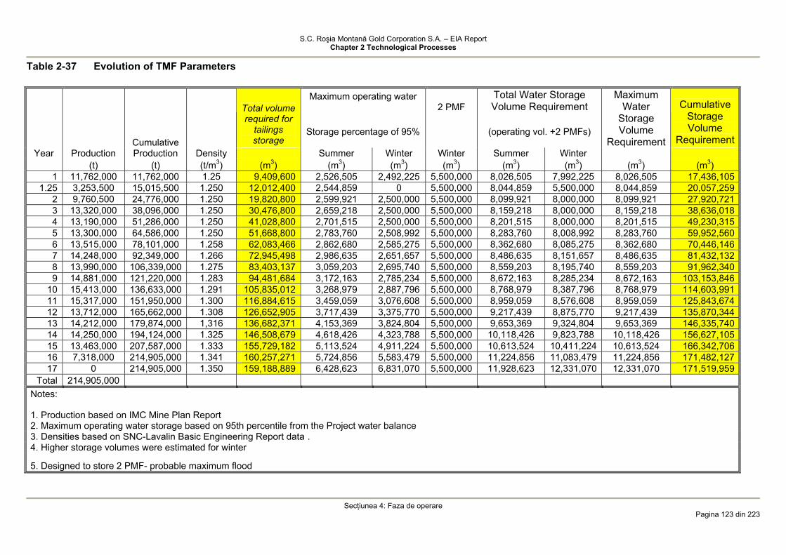
S.C. Roşia Montană Gold Corporation S.A. – EIA Report Chapter 2 Technological Processes
Secţiunea 4: Faza de operare
Pagina 123 din 223
Table 2-37 Evolution of TMF Parameters
Maximum operating water
2 PMF Total Water Storage Volume Requirement
Cumulative
Total volume required for
tailings storage
Storage percentage of 95%
(operating vol. +2 PMFs)
Maximum Water
Storage Volume
Requirement
Cumulative Storage Volume
Requirement Year Production Production Density Summer Winter Winter Summer Winter
(t) (t) (t/m3) (m3) (m3) (m3) (m3) (m3) (m3) (m3) (m3) 1 11,762,000 11,762,000 1.25 9,409,600 2,526,505 2,492,225 5,500,000 8,026,505 7,992,225 8,026,505 17,436,105
1.25 3,253,500 15,015,500 1.250 12,012,400 2,544,859 0 5,500,000 8,044,859 5,500,000 8,044,859 20,057,259 2 9,760,500 24,776,000 1.250 19,820,800 2,599,921 2,500,000 5,500,000 8,099,921 8,000,000 8,099,921 27,920,721 3 13,320,000 38,096,000 1.250 30,476,800 2,659,218 2,500,000 5,500,000 8,159,218 8,000,000 8,159,218 38,636,018 4 13,190,000 51,286,000 1.250 41,028,800 2,701,515 2,500,000 5,500,000 8,201,515 8,000,000 8,201,515 49,230,315 5 13,300,000 64,586,000 1.250 51,668,800 2,783,760 2,508,992 5,500,000 8,283,760 8,008,992 8,283,760 59,952,560 6 13,515,000 78,101,000 1.258 62,083,466 2,862,680 2,585,275 5,500,000 8,362,680 8,085,275 8,362,680 70,446,146 7 14,248,000 92,349,000 1.266 72,945,498 2,986,635 2,651,657 5,500,000 8,486,635 8,151,657 8,486,635 81,432,132 8 13,990,000 106,339,000 1.275 83,403,137 3,059,203 2,695,740 5,500,000 8,559,203 8,195,740 8,559,203 91,962,340 9 14,881,000 121,220,000 1.283 94,481,684 3,172,163 2,785,234 5,500,000 8,672,163 8,285,234 8,672,163 103,153,846
10 15,413,000 136,633,000 1.291 105,835,012 3,268,979 2,887,796 5,500,000 8,768,979 8,387,796 8,768,979 114,603,991 11 15,317,000 151,950,000 1.300 116,884,615 3,459,059 3,076,608 5,500,000 8,959,059 8,576,608 8,959,059 125,843,674 12 13,712,000 165,662,000 1.308 126,652,905 3,717,439 3,375,770 5,500,000 9,217,439 8,875,770 9,217,439 135,870,344 13 14,212,000 179,874,000 1,316 136,682,371 4,153,369 3,824,804 5,500,000 9,653,369 9,324,804 9,653,369 146,335,740 14 14,250,000 194,124,000 1.325 146,508,679 4,618,426 4,323,788 5,500,000 10,118,426 9,823,788 10,118,426 156,627,105 15 13,463,000 207,587,000 1.333 155,729,182 5,113,524 4,911,224 5,500,000 10,613,524 10,411,224 10,613,524 166,342,706 16 7,318,000 214,905,000 1.341 160,257,271 5,724,856 5,583,479 5,500,000 11,224,856 11,083,479 11,224,856 171,482,127 17 0 214,905,000 1.350 159,188,889 6,428,623 6,831,070 5,500,000 11,928,623 12,331,070 12,331,070 171,519,959
Total 214,905,000 Notes:
1. Production based on IMC Mine Plan Report 2. Maximum operating water storage based on 95th percentile from the Project water balance 3. Densities based on SNC-Lavalin Basic Engineering Report data . 4. Higher storage volumes were estimated for winter
5. Designed to store 2 PMF- probable maximum flood
S.C. Roşia Montană Gold Corporation S.A. – EIA Report Chapter 2 Technological Processes
Section 4: Operations Phase
Page 124 of 223
It is evident that the TMF pond storage can accommodate several probable maximum floods estimated at approximately 2,750,000 m3 each, with the exception of a short critical period prior to the first raise of te tailings dam.
4.1.4.7 Management of TMF Seepage
Two scenarios are available for the seepage from the TMF reporting to the secondary containment pond.
It is anticipated that for a period at the beginning of operation, the seepage is conventionally clean water which can be discharged into the Corna Valley.
Immediately after contaminant concentrations higher than the permit limits are detected in the seepage water, seepage will be collected in the secondary containment sump and pumped back to the TMF basin. The treatment method will be identified based on the composition of the seepage water in view of achieving the permit levels for discharge into the receiving stream.
Development of a treatment system for the seepage from the tailings impoundment is a very important component of the long-term TMF water management. This system will be an important aspect of the closure and post-closure phase.
4.1.4.8 Geochemistry of Tailings deposited in the TMF
As the environmental impact during operations is a function of the geochemistry of the tailings deposited in the TMF and seepage that may occur through and under the main dam a detailed analysis of these factors is presented below with special emphasis on:
• Tailings Characterisation; • TMF Decant Water Chemistry; • Seepage Modelling.
Tailings Characterisation
In order to assess the TMF water quality - decant water and seepage through the and under the tailings dam - specific testwork was conducted summarised in the „Tailings management facility geochemistry and water quality Report 2005” [12] by the MWH Inc Mining Group.
Testwork aimed at identifying the main factors influencing the water quality during both the operational and after-closure phase of the waste facility.
At the end of the operational period a volume of approximately 153,000,000 m3 of consolidated tailings and tailings pore water and about 1.000.000 m3 of decant water will be stored in the TMF in areas where there are no beaches.
During operations and an additional period after the deposition of tailings has ceased, the process water will be in contact with the tailings.
All the surveys showed that in time the tailings stored in the TMF have potential for ARD generation. The water pH may be in the range of 2 to 7 depending on the pyrite content and time.
The surveys also focused on the cyanide still reporting to the TMF. Tailings assessment was focused on the following three key issues: • tailings potential to generate acid rock drainage (ARD); • changes in tailings chemistry with time, if tailings are exposed to ARD generation
conditions; • chemistry of leachate generated by the dissolution of soluble minerals in tailings. It is evident that the tailings have potential for ARD generation. As the operating and
TMF closure methods are BAT the potential for ARD generation will be minimised and controlled, as specified in Section 3.5. The process water discharged with the solid tailings into the TMF will largely dominate the TMF water chemistry. If the tailings are drained (in the tailings beach) and re-moistened through precipitation a different quality water will result due to the dissolution of soluble minerals in tailings.
S.C. Roşia Montană Gold Corporation S.A. – EIA Report Chapter 2 Technological Processes
Section 4: Operations Phase
Page 125 of 223
The tailings and waste rocks consist of a wide range of metals. In an oxygen free environment, minerals do not oxidize, sulphides are thermo-dynamically stable and have low chemical solubility. Exposure to oxygen supplied from air initiates a series of bio-geo-chemical processes in the above surface rocks which may result in ARD generation. The effect of the exposure intensifies with the grain size decrease as a result of specific surface area increase. Therefore, the sulphides in milled tailings are susceptible to oxidation.
If the tailings contain neutralizing minerals - such as carbonates - the resulting acid may react with these minerals, it is used up and the medium becomes neutral. The solute metals precipitate and are not therefore discharged from the system. Other acid-consuming minerals are the aluminium silicates such as potash feldspar. The aluminium silicate dissolution is kinetically controlled and can not maintain a neutral pH.
The interaction between the acid generating oxidation of sulphide minerals and dissolutions of acid-consuming minerals dictates the pore water and drainage water pH which influences the metal mobility.
The test results indicated that the tailings have the potential to become acidic in the presence of oxygen and water. At the same time a process for inhibiting ARD generation was identified, inhibition caused by the secondary precipitation of some minerals on the sulphide grains thus covering their active surface.
The sulphide content of tailings is 1-2%, rarely higher. The presence of carbonates in tailings inhibits the ARD generation process, however
the carbonate content is very low, between 0.2% and 0.8%, rarely reaching 1.5%. The tests confirmed that in an early phase when the process water pH is alkaline and
there is a neutralizing potential in the tailings ARD generation does not immediatly occur. The pH will drop from 8 - 8.5 down to approximately 6.5 only after 26 tailings moistening - dewatering cycles, as per the tests conducted by MWH [12].
Due to the rapid deposition of the tailings in the TMF and flooding of most of the tailings, a significant oxidation which may facilitate ARD generation is not likely to occur. A significant generation of ARD in the TMF is not expected in the operational phase.
The short-term leaching tests indicated that the storm water in contact with tailings will generate a water which meets the requirements of the Romanian Technical Norms for Water Protection - NTPA 001/2005 - with the exception of a minor exceedance of the pH. The long-term tailings leaching tests indicated that manganese levels may also be exceeded.
Nămolul rezultat de la instalaţia de tratare a ARD din Cetate, care se depune în TMF într-un raport de mase de 1 parte nămol la 4.000 părţi steril de la procesarea minereului (0,025%), are un potenţial de generare a unui levigat care nu satisface cerinţele NTPA 001 în ceea ce priveşte conţinutul în Ca, sulfat şi solide totale dizolvate şi nici pH-ul.The ARD Treatment Plant sludge deposited within the TMF in a sludge/ore processing tailings mass ratio of 1:4,000 (0.025%) has the potential to generate a leachate which does not comply with the requirements of NTPA 001 with respect to sulphate, calcium and total dissolved solids content and pH levels. Dar datorită cantităţii mici nu este de aşteptat să aibă un impact semnificativ asupra calităţii apei din TMF.However, due to the small amount it is not expected to generate a significant impact on the TMF water quality.
TMF Decant Water Chemistry
A significant volume of process water resulting from the settling of the solids in the tailings slurry will be stored in the TMF during the operational phase tailings slurry, the water will be continuously recycled to the ore processing plant. In this way a closed circuit will be developed and no waste water will be discharged to the existing stream channels or groundwater system during normal operations or even extreme rainfall events. The TMF provides full containment of two consecutive Probable Maximum Floods (PMFs). In case of an extreme precipitation event when the TMF storage capacity is exceeded (the probability of this event to occur is very low), water surplus conditions may require discharge in order to maintain the normal operating volume in the tailings pond. For this situation a cyanide detoxification plant is provided to reduce the WAD cyanide concentration in diluted waters.
S.C. Roşia Montană Gold Corporation S.A. – EIA Report Chapter 2 Technological Processes
Section 4: Operations Phase
Page 126 of 223
The estimations for the general decant water chemistry and cyanide concentration chemistry are described below.
TMF Decant Water Chemistry
In order to assess the chemistry of the decant water testwork was conducted in 2004 on the same RM1, RM2 and RM3 samples which were submitted for various detoxification tests. The tests results showed that calcium, sulphate and ammonium are the only constituents exceeding the requirements of the NTPA 001/2005. Arsenic, copper and molybdenum occur in concentrations permitted by the standard or slightly below permissible limits. Any dilution due to rainfalls will reduce these concentrations below permissible limits. Also, the cyanide concentration exceeds the permissible limits, however this issue will be discussed in the following section.
Cyanide Degradation Chemistry in the TMF Decant Water
Investigations were carried out in order to determine the cyanide occurrence in the TMF and cyanide concentration and persistence. It is recognised that cyanide tends to reduce its concentration by precipitation of some cyano-metal complexes and by volatilization of hydrocyanic acid from the decant water. Free cyanide (uncomplexed) will directly volatilize, while other cyano-metal complexes require ultraviolet light to degrade [Mudder et al., 2001].
Many of the factor which influence the cyanide concentration attenuation are locally specific, thus the estimations of cyanide attenuation levels have significant uncertainties associated with them.
Therefore, in order to predict parameter for such a process a specific model was developed by Botz and Mudder [4] who are internationally recognized experts in the use of cyanide in the mining industry and associated environmental impacts.
The following conclusions resulted from the cyanide degradation modelling but it should be noted that these conclusions are only informative and may not be considered final, as specified in the MWH Report [12].
The decrease of cyanide concentration is a complex process that may include volatilization, oxidation, photolysis, hydrolysis, precipitation, complexing and adsorption. However, the primary method to for cyanide removal is the volatilization of the hydrocyanic acid (HCN) from the water surface.
It was found that HCN removal from the supernatant water is done according to a linear equation which means that HCN loss is directly proportional to the HCN concentration in solution. Mathematically, this is reflected by the following equation (1):
[ ] [ ]HCNkdt
HCNd−= (1)
where: [HCN] represents the HCN concentration in the TMF basin supernatant solution. t - time k - first order volatilization coefficient
The k coefficient for a TMF supernatant considered as fully mixed is given by the following formula:
vkVAk ⎟
⎠⎞
⎜⎝⎛= (2)
where: A - supernatant surface exposed to atmospheric conditions V - supernatant volume Kv – first order volatilization coefficient for HCN
Performing the replacements in equation (1) it results: [ ] [ ]HCNk
VA
dtHCNd
v= (3)
The HCN volatilization coefficient is primarily a function of temperature, solution mixing and wind.

S.C. Roşia Montană Gold Corporation S.A. – EIA Report Chapter 2 Technological Processes
Section 4: Operations Phase
Page 127 of 223
For the purposes of this model the Kv[HCN] coefficient was considered dependent solely on temperature.
Due to the high stability of iron cyanic complexes in the surface water and groundwater they are only slightly dissociated in ambient conditions, except when they are exposed to ultraviolet and visible radiations (sun light). Then, these complexes dissociate by photolysis with generation of free cyanide. In absence of sun light, the cyanic complexes of iron are stable and natural attenuation occurs at low rates. Iron cyanide photolysis equation is:
[ ] [ ]CNFekdt
CNFedp −−=
− (4)
where: [Fe-CN] is the concentration of iron cyanide in solution kp – photolysis coefficient, which is a function of the sun light intensity, pH,
temperature, iron cyanide concentration, free surface of supernatant and supernatant depth. Complex cyanide dissociation to free cyanide which can re-complex with other
metals, such as copper or can volatilize from solution as HCN is achieved according to equation (3).
Iron can form complexes with cyanide in both ferrous and ferric form, however, ferric complex is normally predominant.
Equations (3) and (4) are the fundamental formulas used by Botz and Mudder in their study [4] to estimate the cyanide removal rate from the TMF decant water as a result of HCN photolysis and volatilization.
The decant water cyanide removal modelling was based on the following assumptions:
decant water was assumed fully mixed; pH of TMF decant water was assumed consistent throughout the TMF area and
during the entire period (pH=8÷8.5); it was assumed the chemistry of the tailings deposited in the TMF is similar to the
chemistry of the detoxified slurry discharged into the TMF; three potential scenarios were considered in relation to the total content of cyanide,
readily releasable cyanide and metals in the tailings slurry stored in the TMF. Case Cu Fe Ni Zn Total
Cyanide WAD Cyanide
Case 1 0.8 0.9 0.22 <0.01 3.9 1.4 Case 2 5.0 1.0 0.3 0.1 8.0 5.2 Case 3 10.0 1.0 0.3 0.1 13.0 10.2
it was assumed that the seepage metal and cyanide content is the same as for the
slurry discharged into the TMF, affected by a dilution factor (F). This factor depends on certain processes such as anaerobic biological processes, adsorption and complexing. Three factors were considered in the modelling: 0.9; 0.7 and 0.5.
MWH indicated that the water contained in the ARD treatment plant sludge deposited in the TMF has the same chemistry for common pollutants as the TMF decant water;
the following supernatant monthly temperatures and ice cover levels were assumed over a period of one year:
January 40C 95% February 40C 95% March 40C 95% April 80C 50% May 120C 0% June 160C 0% July 200C 0% August 240C 0%

S.C. Roşia Montană Gold Corporation S.A. – EIA Report Chapter 2 Technological Processes
Section 4: Operations Phase
Page 128 of 223
September 200C 0% October 160C 0% November 120C 0% December 80C 50%
• the water balance provided by MWH was taken into consideration.
Modelling Results The conclusions drawn from the numeric modelling of the cyanide degradation
process are as follows: • for degradation of cyanide in an effluent with a pH level of 8 and a readily
releasable cyanide concentration of 10 mg/l, the concentration in the TMF pond during operation, taking into account natural degradation and dilution, is estimated at 2 up to 6 mg CNu.e.-/L. The concentration level varies depending on the season. A time period of around 3 years after closure is assumed for the Cyanide concentration to drop below 0.1 mg/l [12];
• a more significant decrease of the concentration occurs for higher initial concentrations. Lower concentrations will be obtained during summer months; during winter the cyanide concentrations will be higher as the low temperatures and frost will inhibit reduction of cyanide concentrations;
The following table shows the estimated levels for the cyanide content of the decant water during operation and post-closure, as a function of the content of the slurry discharged into the TMF [4]:
Cyanide Content of Detoxified Slurry
Cyanide Content of Decant Water during Operation (Years 1-16)
Cyanide Content of Decant Water after Closure (Year 20) Case
Total (mg/l) CNWAD-
(mg/l) Total (mg/l) CNWAD-
(mg/l) Total (mg/l) CNWAD-
(mg/l) 1 3.9 1.4 1.5-3 0.8-1.1 <0.01 <0.01 2 8.0 5.2 2-5 1.5-3 <0.01 <0.01 3 13.0 10.2 3-8 2-6 <0.01 <0.01
It is estimated that WAD cyanide concentrations will be below 1% of the initial
cyanide concentration in a period of one year after closure (below 0.1 mg/l, respectively). It is estimated that a similar level of concentration decrease will be also achieved for
total cyanide; this is only in part applicable as it is estimated that a significant part of the total cyanide is WAD and only a small part consists of ferro-cyanic complexes.
Similar to WAD cyanide, total cyanide concentration will drop below 1% of the initial concentration 1 to 3 years after closure.
pH levels in the TMF are expected to be 8 up to 8.5.
It is estimated that for this pH range only minor changes of the WAD cyanide concentrations may occur CNWAD
-. If pH drops to 7.5 the volatilization process will intensify resulting in lower cyanide
concentrations in the TMF during summer months. For any pH value between 7.5 and 8.5, cyanide degradation quickly results in
concentrations below 1% of the initial cyanide concentration during the first three post-closure years.
• With respect to seepage it was concluded that the dilution factor during operation has no significant effect while the total post-closure cyanide concentration drops below 0.1 mg/l in a period of one year after slurry discharge to the TMF has ceased.
• The tested model proved not to be very sensitive for acceptable variation ranges of the seepage dilution, decant water temperature or ice cover persistence time.
S.C. Roşia Montană Gold Corporation S.A. – EIA Report Chapter 2 Technological Processes
Section 4: Operations Phase
Page 129 of 223
Impact of probable maximum floods (PMF) may be a concern for the TMF decant water. The TMF is designed to provide full containment of two consecutive PMF events, however it may be required to discharge excess water to the environment in a controlled manner in order to ensure the normal operating level in the TMF. A reduction of 50% is typically assumed by natural degradation/attenuation. In case 1 or 2 extreme events occur there is sufficient storage capacity in the TMF pond and the potential dilution may be much higher. However, if this capacity is exceeded, a cyanide detoxification plant is provided for the treatment of low cyanide concentration water prior to discharge to the environment. For decrease of other constituent concentrations occurring in the TMF decant water the same 50% can be applied.
Seepage Chemistry and Modelling
TMF seepage will occur in relation to the drainage system and foundation materials. During operations all seepage will be collected in the secondary containment basin and pumped back to the TMF, thus no release to the environment should occur under normal operating conditions.
In order to assess the potential impact of a spill or to develop treatment alternatives it is important to understand the seepage chemistry and evolution with time.
The TMF will be initially filled with 1-2 million m3 of fresh water to ensure start-up of gold ore processing. At first, tailings discharge will be carried out from the main dam crest (Corna dam) and the slurry will mix with the water stored in the TMS.
Therefore, the initial seepage will consist of fresh water and will subsequently contain increasingly higher amounts of process water. It is likely that no seepage occurs in the initial phase, in particular when the hydraulic head upstream of the starter dam is relatively low.
Seepage modelling was performed by MWH [13a, 13b, 13c, 13d] in order to estimate the seepage flow rate and chemistry both in the initial and final stage of the TMF and secondary containment dam.
Starter Dam Seepage
Three cross sections, one on the right abutment, left abutment, and the centreline, were developed for the TMF Dam seepage modelling. The centreline section was idealised to include the lowest points at the upstream, core, and downstream extents of the dam, similar to the section in Drawing 2.45. Medium tailings are assumed to be within 180 meters of the dam, and fine tailings within 380 meters. The TMF was analysed for 5 cases [13a];
• Case 1: the dam was analysed with an upstream liner; • Case 2: the dam was analysed without an upstream liner; • Case 3: the dam was analysed with a 40 m deep by 1 m wide grout curtain with a
permeability of 10-7 m/sec; • Case 4: a 30 m deep by 2 m wide slurry wall, with a permeability of 10-8 m/sec, is
installed; and • Case 5: an upstream sump is included. All the materials in the analysis were assumed to be isotropic, except for the bedrock,
which was assumed to be 10 times as permeable in the horizontal direction as in the vertical direction. Seepage properties used for the analysis are shown in the following table: Table 2-38. TMF Foundation and Fill Materials Seepage Properties Zone Material Specification Seepage Engineering Properties Centerline Right Left Fill, Grout Curtain and Tailings
kh (cm/s)
b). (m)
kh (cm/s)
b). (m)
kh (cm/s)
b). (m)
Core (Zone 1)
TMF footprint, basin and core trench excavation or pre-stripping La Piriul Porcului Sandstone
1x10⁻⁶ (3) - - - - -
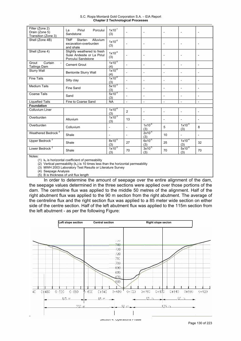
S.C. Roşia Montană Gold Corporation S.A. – EIA Report Chapter 2 Technological Processes
Section 4: Operations Phase
Page 130 of 223
Filter (Zone 2) Drain (Zone 5) Transition (Zone 3)
La Piriul Porcului Sandstone
1x10⁻¹ (3) - - - - -
Shell (Zone 4B) TMF Starter- Alluvium excavation-overburden and shale
1x10⁻⁶ (3) - - - - -
Shell (Zone 4) Slightly weathered to fresh Sulei Andesite or La Piriul Porcului Sandstone
1x10⁻⁶ (3) - - - - -
Grout Curtain -Tailings Dam Cement Grout 1x10⁻⁵
(4) - - - - -
Slurry Wall Bentonite Slurry Wall 1x10⁻⁶ (4) - - - - -
Fine Tails Silty clay 1x10⁻⁶ (3) - - - - -
Medium Tails Fine Sand 5x10⁻⁵ (3) - - - - -
Coarse Tails Sand 5x10⁻⁴ (3) - - - - -
Liquefied Tails Fine to Coarse Sand NA - - - - - Foundation Colluvium Liner 1x10⁻⁶
(3) 2 - - - -
Overburden Alluvium 1x10⁻³ (3) 13 - - - -
Overburden Colluvium - - 1x10⁻⁶ (3) 5 1x10⁻⁶
(3) 8
Weathered Bedrock 2 Shale - - 2x10⁻⁴ (3) 10 - -
Upper Bedrock 2 Shale 8x10⁻⁵ (3) 27 6x10⁻⁵
(3) 25 1x10⁻⁴ (3) 32
Lower Bedrock 2 Shale 1x10⁻⁵ (3) 70 3x10⁻⁵
(3) 70 5x10⁻⁶ (3) 70
Notes: (1) kh is horizontal coefficient of permeability (2) Vertical permeability (kv) is 10 times less than the horizontal permeability (3) MWH 2003 Laboratory Test Results or Literature Survey (4) Seepage Analysis (5) B is thickness of unit flux length
In order to determine the amount of seepage over the entire alignment of the dam, the seepage values determined in the three sections were applied over those portions of the dam. The centreline flux was applied to the middle 50 metres of the alignment. Half of the right abutment flux was applied to the 90 m section from the right abutment. The average of the centreline flux and the right section flux was applied to a 85 meter wide section on either side of the centre section. Half of the left abutment flux was applied to the 115m section from the left abutment - as per the following Figure:
Left slope section Central section Right slope secion
S.C. Roşia Montană Gold Corporation S.A. – EIA Report Chapter 2 Technological Processes
Section 4: Operations Phase
Page 131 of 223
The results of the seepage analysis for each of the five cases are shown in the
following table: Starter Dam Seepage Rates Case Seepage (m3/h) Case 1 10.1 Case 2 11.6 Case 3 9.77 Case 4 6.41 Case 5 8.79
Final Dam Seepage The TMF main dam (Corna Dam) was analysed for the same cases as the starter
dam with one additional case [13b]: • Case 6, was analysed with the TMF holding the PMF for an extended period.
The results of each case analysed are presented in the following table: TMF Final Dam Seepage Rates Case Seepage (m3/h) Case 1 82.4 Case 2 76.2 Case 3 81.9 Case 4 83.4 Case 5 45.4 Case 6 1.490
MWH has also conducted a sensitivity analysis of the seepage through the final dam [13d] with respect to geometry, permeability and limiting conditions.
It was assumed that: • In the waste materials, foundation and dam there is a uniform flow condition; • The starter dam crest elevation is +733 m; • Seepage is not included in the model; • In the dam centerline:
o The thickness of the alluvium is approximately 10 m and will be stripped from both shells;
o The upper bedrock is approximately 35 m in thickness; 35 m o The upper bedrock is approximately 35 m in thickness; 40 m.
A parametric survey was conducted in order to check the upstream configuration of the starter dam which contains zones of different permeability.
The results showed that the sump which reduces the pressure in the alluvium and clay layer under the upstream dam shell may reduce, increase respectively the piezometric elevation.

S.C. Roşia Montană Gold Corporation S.A. – EIA Report Chapter 2 Technological Processes
Section 4: Operations Phase
Page 132 of 223
Secondary Containment Dam Seepage Three scenarios were examined for the Secondary Containment Dam such that the
water level in the Secondary Containment Pond was set at the minimum normal operating level of El. 642 m and at maximum normal operating level of El. 639 m and the rainfall event with a return period of 100 years when the level in the SCS sump is at El. 650 m. In all three scenarios, It was assumed 639 m downstream and stationary conditions for the secondary containment dam [13c].
The effects of seepage from higher heights and peripheral drainage collection were ignored.
The bentonite slurry wall at the Secondary Containment Dam is 3 m thick and 1 m wide. The seepage characteristics used for the analysis are presented in the table below:
Summary of the Seepage Characteristics through the SCS Dam Zone Material Specification Centerline Seepage Rockfill, Grout Curtain and Tailings (cm/s) (m) Core (Zone 1) SCS Dam sump excavation and stripping La
Piriul Porcului sandstone 1x10⁻⁶ (3) -
Filter (Zone 2) Drain (Zone 5) Transition (Zone 3)
La Piriul Porcului Sandstone 1x10⁻¹ (3) -
Shell (Zone 4) Slightly weathered to fresh Sulei Andesite 1x10⁻¹ (3) - Slurry Wall Bentonite Slurry 1x10⁻⁶ (4) - Foundation Overburden Alluvium 1x10⁻³
(3) 10 to 13 Overburden Colluvium - - Weathered Bedrock 2 Shale - - Upper Bedrock 2 Shale 1x10⁻⁴
(3) 12 to 18 Lower Bedrock 2 Shale 2x10⁻⁵
(3) 14 to 21 Notes:
(1) kh is horizontal coefficient of permeability (2) Vertical permeability (kv) is 10 times less than the horizontal permeability (3) MWH 2003 Laboratory test results or literature survey (4) Seepage Analysis (5) B is thickness of unit flux length
The results obtained by modelling are presented in the table below: Results of seepage modeling through the SCD
Case Minimum sump level Maximum sump level 100-yr Flood Location Seepage (m3/sec.) Seepage (m3/sec.) Seepage (m3/sec.) Core 1.15 x 10⁻⁵ 3.37 x 10⁻⁵ 6.37 x 10⁻⁵ Upper Bedrock 7.66 x 10⁻⁵ 1.87 x 10⁻⁴ 3.03 x 10⁻⁴ Lower Bedrock 6.80 x 10⁻⁶ 1.61 x 10⁻⁵ 2.56 x 10⁻⁵ Total 9.49 x 10⁻⁵ 2.37 x 10⁻⁴ 3.92 x 10⁻⁴ Modelling of Contaminant Transport [14]
The TMF basin and dam were designed to minimize seepage. For this purpose within the TMF basin a compacted colluvial layer which will provide a barrier layer to reduce seepage from the TMF basin, a low permeability core and a drainage channel at the base of the starter dam will be developed. However, the potential still exists for seepage at the downstream dam end.
Therefore, a secondary retention dam was designed downstream of the tailings dam. This will include a cutoff trench at the dam foundation and a sump behind the dam. The water level in the sump will be maintained at a lower elevation with respect to the groundwater level and will be used to collect groundwater.
Seepage will reflect the composition of the process water retained within the pores of the tailings. However, the chemical reactions resulting from the tailings exposure to atmospheric oxygen and carbon-dioxide should also be considered.

S.C. Roşia Montană Gold Corporation S.A. – EIA Report Chapter 2 Technological Processes
Section 4: Operations Phase
Page 133 of 223
The tailings will accumulate in the TMF at a rate of raise of approximately 4-8m/year. At this accumulation rate there is minor opportunity for oxidation and ARD generation by Year 16 of Project operations and even a short period afterward. During ore processing operations the tailings will be permanently covered by fresh tailings and therefore the saturation level will be maintained high, reducing oxygen ingress and oxidation. Testing has indicated that ARD generation will be slowed down by moistening - dewatering successive cycles with the probability that ARD generation will not occur during operations.
In year 16 of operations the gold ore processing will cease and approximately 169,400,000 m3 of tailings will be deposited in the TMF. Assuming a pore volume of 40% and a saturation degree of 85% it results that there will be approximately 63 million m3 of water retained within the pores of the tailings deposited in the TMF. The tables above indicate that seepage flow rates are of approximately 45.4m3/h. Therefore 1-2% of the water retained in the tailings will seep from the TMF every year. For this reason, seepage water will continue to be a significant component of the process effluents for many years after closure.
Typically, the ARD generation process consists of the following chemical reactions: FeS2 + 7/2 O2 + H2O → Fe2+ + 2SO4
2- + 2H+ for pyrite oxidation; FeS2 + 15/4 O2 + 7/2H2O → Fe(OH)3 + 2SO4
2- + 4H+ for oxidation with ferric hydroxide precipitation; and FeS2 + 4Fe3+ +8 H2O →15 Fe2+ + 2SO4
2- + 16H+ for oxidation with ferric ion. All these reactions will produce acidity and sulphate ions. Soluble iron may result, but
it will precipitate as hydroxides and hydroxysulphate. ARD generation is a cyclic process with limited sulphide oxidation in both dry and wet
climatic conditions [15]. The process may start with drying of wet pyrite grains. As the grain surface dries out, the grains are exposed to an optimum mixture of water and oxygen and oxidation occurs. Bacteria may also plat an important role as a catalyst for this pH dependant reaction. In the maximum oxidation condition, the resulting ARD has little mobility being captured within the pores either as fluids and retained by capillarity forces or as highly soluble mineral salts formed with mineral grains. Some mineral salts can migrate to the tailings surface. During the subsequent precipitation ARD retained within the pores and dissolved mineral salts may flow downward through the interstitial capillary columns. Acidic salts reaching the upper part of the tailings may be washed and therefore reach the decant water area.
ARD seeped in the deposited tailings which consume acid by dissolution will react with the mineral grains. These reaction may result in the release of heavy metals (copper, lead, zinc etc.), but may also result in the neutralization and precipitation of other secondary minerals.
The ARD generation potential is decreased by neutralization allowing for ARD generation in the deeper zones. When the tailings permeability is low, minerals such as carbonates and feldspar may, if present, contribute to the ARD neutralisation. This process is indicated by the high concentration of potassium and silica ions. As the acid flow advances, many other secondary minerals previously formed will be dissolved and mostly precipitated and the acidity is neutralised. An effect of the acid flow migration may be the formation of the "hard shale" layer. This "hard shale" layer will decrease the tailings permeability and can significantly limit the ARD generation depth and slow down the ARD generation and migration by limiting the water and oxygen ingress. This type of layer was studied and observed in a number of tailings deposition ponds [16].
ARD generation is also slowed down by the drawdown of the dried tailings area. TMF closure will start shortly after completion of ore processing. The main
component of the closure will be the placement of a subsoil and topsoil layer on the tailings
S.C. Roşia Montană Gold Corporation S.A. – EIA Report Chapter 2 Technological Processes
Section 4: Operations Phase
Page 134 of 223
surface. The cover will be designed to reduce seepage and exposure to oxygen which will result in the reduction of oxidation and ARD generation and transport of contaminants.
In order to estimate the time when seepage containing cyanide will reach the secondary containment sump, MWH has modelled the contaminant transport based on the PHREEQC model of the US Geological Survey. The modelling objectives were as follows:
• estimation of cyanide concentrations in the sump downstream of the starter dam during years 1 and 10 after commencement of the slurry discharge into the TMF containing 22 or 10 mg/l cyanide (WAD cyanide);
• estimation of the time required for the seepage collected in the sump downstream of the starter dam to reach a cyanide concentration of 0.01 mg /l.
• The modelling was also based on the following aspects: • spatial geometry of each hydrostratigraphic unit and tailings material; • types of rocks and hydraulic conductivities; • starter dam configuration; • hydraulic head conditions in the tailings deposition pond; • a constant hydraulic level at the upstream end of the TMF at El. 736 m simulating the
decant water level; • a constant hydraulic level at the downstream end at El. 615 m simulating the level in
the sump behind the Secondary Containment Dam. All other conditions were assumed to the same as for seepage modelling. In summary, the modelling results show that within 5 years the cyanide concentration
will not reach 0.01 mg /l in the SCS sump. This concentration can be reached between years 7.5 – 8 of the Project life considering an initial concentration of both 10 mg/l and 22 mg/l. [14].
As per the MWH Report this modelling is for information only. The actual TMF operation conditions may lead to significant changes due to the following:
• actual hydraulic conductivities may differ for each geological unit due to the heterogeneity caused by the changes in particle size and fracturing;
• cyanide degradation may occur at rates higher or lower than those expected; • tailings saturation varies within the TMF (in the tailings beach and decant water
areas); • changes also occur with respect to the distance from the dam to the decant water
area. 4.1.5 Auxiliary processes 4.1.5.1 Lime management (storage, preparation, use)
Exhibit 2.25 shows the lime preparation flowsheet Lime is supplied in granulated form (-25mm) and prepared on two lines, namely:
Line 1 producing lime powder; Line 2 producing milk of lime;
Line 1 producing lime powder Granulated lime is unloaded mechanically in a hopper from where it is reclaimed by a
vibrating feeder and conveyor and transported to a silo equipped with dust retention filter. The silo is equipped with mechanical and ultrasonic level detection systems. From the silo, lime is unloaded onto a belt conveyer equipped with weighing device, fed into the hammer mill and ground to the size of 2 mm. Ground lime is transported to the SAG mill. Lime addition is controlled by the variation of the belt conveyer speed and quantity is calculated depending on the pH required in the CIL plant. Line 2 producing milk of lime
Granulated lime is unloaded mechanically in a hopper from where it is reclaimed by a vibrating feeder and conveyor and transported to a bin equipped with dust retention filter. The bin is equipped with mechanical and ultrasonic level detection systems. Lime is
S.C. Roşia Montană Gold Corporation S.A. – EIA Report Chapter 2 Technological Processes
Section 4: Operations Phase
Page 135 of 223
unloaded from the silo into the hammer mill by way of a variable speed vibrating feeder. The lime ground in the hammer mill is unloaded onto a belt conveyer fitted with weighing device and added in the lime hydration mill. Ground material is sized in cyclones. Cyclone underflow is returned to the mill. Overflow is discharged by gravity into the milk of lime tank.
The milk of lime mill will operate approximately 3 hours/day. In case of maximum lime use, the mill may operate up to 4 hours/day.
Addition of milk of lime
Milk of lime will be pumped in closed circuit by way of pumps (one duty and one standby) to ensure continuous distribution through the CIL circuit, cyanide detoxification circuit and ARD treatment plant with the excess being returned to the milk of lime tank. A dosing valve fitted on the return pipe is used to ensure suitable pressure in the cyanidation line. Pressure is indicated locally. Milk of lime is added in the detoxification plant, ARD treatment plant and CIL plant (if necessary) by way of control valves, in separate pipes within the closed circuit in order to maintain the desired pH. The lime addition line includes the interlocking system.
4.1.5.2 Reagent Management (storage, preparation, use)
There will be a number of chemicals and reagents required for the project apart from sodium cyanide and lime. Each of these chemicals and reagents will be stored on site in varying quantities. The storage and handling areas will be designed and constructed to reduce possible health impacts to the workers and environs. The management of these chemicals will be governed by the measures included in the Emergency Preparedness and Spill Contingency Plan (see Plan I of the Roşia Montană Project Environmental and Social Management System). These measures will be developed and applied in order to further reduce potential impact to people and environment.
Sodium Cyanide (Exhibit 2.26)
Sodium cyanide is transported to the Project site by truck. Each ISO container contains around 20 tonnes of sodium cyanide in briquette form. The cyanide dissolution system will be provided by the supplier. The process for obtaining the cyanide solution is fully automatic, initiated by the driver and/or by the reagent operator.
Typically, the content of three containers per day is used. Process water is added with cyanide in the mixing tank (17 m3 useful volume and 22.6 m3 total volume), which has the same capacity as an ISO container. The flow rate is indicated locally and quantity is measured by the tank level indicator. Sodium hydroxide is added (if necessary) in the cyanide mixing tank to maintain pH above 11.5 and prevent release of HCN from the sodium cyanide solution.
The solution is pumped from the cyanide mixing tank by way of the cyanide transfer pump into the truck’s container tank to dissolve the cyanide briquettes. Dissolved cyanide is pumped and unloaded from the truck’s container tank into the cyanide mixing tank. The circulation of the solution from the ISO container into the mixing tank takes 2-4 hours and ensures full dissolution of the cyanide briquettes. The ISO container is fully emptied at the end of the cycle using compressed air.
The obtained solution with concentration of 20% NaCN (W/V) is pumped into the cyanide storage tank which is 6.5 m in diameter and 7 m in height (volume of 216 m3) and fitted with level indicator. This indicates what quantity of cyanide is used and how much is added from the ISO containers.
Dosing
The cyanide solution is pumped in closed circuit by way of the distribution pumps (one duty and one standby) to the CIL circuit and then returned to the storage tank. The circuit pressure is maintained by way of a manually operated shutter valve. Most of the cyanide is added in the CIL circuit feed tank using control valve that controls the minimum level by way of the magnetic level indicator. The addition of cyanide in the CIL tanks is controlled manually by way of needle valves fitted with local level indicator. The cyanide
S.C. Roşia Montană Gold Corporation S.A. – EIA Report Chapter 2 Technological Processes
Section 4: Operations Phase
Page 136 of 223
dosing pumps (one for each elution column) supply cyanide solution to the elution circuit, as required. The flow rate of each pump is monitored and controlled by the variation of the dosing pump speed.
Sodium Hydroxide (caustic soda) Exhibit 2.26
It is supplied in 1 tonne big-bags and is prepared 20% (W/V) solution with fresh water. Soda dissolution is a semi-automatic operation, conducted by the operator. The operator controls the opening of the fresh water valve in the soda mixing tank. The flow rate is indicated locally and quantity is measured by the tank level indicator. The operator turns on the tank agitator after having added 4 bags. After the pre-set mixing time, the agitator is turned off and solution is pumped to the storage tank. The 50 m3 storage tank is fitted with level indicator of which alarm notifies the operator that a new dissolution bach must be initiated.
Note: Dissolution of caustic soda generates significant heat. Insufficient mixing may cause dangerous and unexpected heating and strong eruptions in the mixing tank. It is essential that the agitator be turned on prior to adding solid soda.
Copper Sulphate (Exhibit 2.27)
Copper sulphate is supplied in 700 – 1000 kg big-bags and is mixed with water in the copper sulphate tank. The copper sulphate solution (Cu SO4) is added in the two detoxification agitators, by way of separate dosing pumps. No separate storage tank is provided as it is assumed that the content of the dissolution tank ensures the amount of copper sulphate necessary to detoxify the tailing slurry.
The copper sulphate dissolution tank, (with 27 m3useful volume and 32 m3 total volume) will be equipped with a local contaminant collection and discharge system, at an air rate of 1,000 Nm3/h.
Sodium Metabisulphite (Exhibit 2.27)
The sodium metabisulphite (SMBS) is supplied in 700-1000 kg big-bags, mixed in the metabisulphite agitator (with 40 m3 useful volume and 50.3 m3 total volume) and transferred periodically in the SMBS storage tank (with volume of 170 m3). The solution is added by way of separate dosing pumps. A low pH alarm will be interconnected with the emergency valve of the metabisulphite dosing pumps, which will stop the SO2 supply and thus prevent cyanide volatilisation.
(Exhibit 2.29)
Flocculant is supplied in 25 kg plastic bags and mixed in its own mixing system consisting of a dry reagent tank, exhauster and mixing tank. Flocculant dissolution will be fully automatic being initiated by the level indicator from the flocculant storage tank. The operator will have to maintain adequate amount of dry flocculant in the feed tank. The control system will ensure automatic control and adjustment of the water addition, transfer of dry flocculant to the dispersion area, mixing time for solution maturation and transfer to the storage tank. The storage tank is fitted with a level indicator which initiates mixing and transfer and an additional alarm to warn the operator of any problems that may occur. The flocculant preparation system is fully automatic. Two sets of of pumps ensure the addition of flocculant in the tailings thickener and ARD treatment plant.
Hydrochloric Acid (Exhibit 2.28)
Hydrochloric acid is supplied in liquid form, in closed tanks, from which it is transferred directly to the 50 m3 storage tank. The acid is added directly in the acid-wash column by way of the dosing pumps.
Other reagents and consumable used

S.C. Roşia Montană Gold Corporation S.A. – EIA Report Chapter 2 Technological Processes
Section 4: Operations Phase
Page 137 of 223
Carbon dioxide - used to control the pH of water treated in the ARD treatment plant, will be supplied in special bottles. Its management and addition will be made through a special system, provided by the supplier.
Chlorine, active carbon and soda ash - for treating drinking water. Chlorine will be supplied in special bottles and active carbon and soda ash will be supplied in bags. These will be stored in dedicated storage facilities.
Salt - for water softening, will be supplied in bags and stored in a storage facility. Active carbon – for the CIL circuit. Will be supplied in bags and stored in the active
carbon storage facility. The best management practices will be employed for the transport, storage and
handling of hazardous materials on site in order to minimise potential accidental releases to the environment and facilitate cleaning activities.
4.1.5.3 Thermal plant
It is designed to heat the buildings and provide hot water for domestic use. The thermal plant will be equipped with a boiler of 10,500 kW thermal power. The boiler will operate on liquid fuel, with a maximum consumption of 927 kg/h (1.8 m3/h) that corresponds to the rated capacity. During the cold season, to ensure additional heating of the buildings, the plant will operate at an average capacity of 43%, with 400kg/h (0.8 m3/h) consumption. Exhaust gas will be released through a 30 m high stack with 1 m internal diameter.
4.1.5.4 Emergency electrical power generator
It complies with the provisions of BAT Chap. 4.3.11.8 in terms of safety measures for cyanide management (EU Reference Document on BAT for Management in Mining Activities of March 2004). It will be used in case of network power failure, in order to avoid shutdown of key equipment and plants on site, including of certain environmental protection equipment/plant. The generator will have an installed power of 2,200 kW and will be equipped with diesel engine and NOx emission control system. The diesel fuel used will have sulphur content below 1%. Combustion products will be released through a 20 m high stack, with internal diameter of 0.8 m, exhaust rate of 48,500 m3/h and exhaust discharge speed of 26,8 m/s.
4.1.5.5 Fuel Storage Facility
The plant site fuel storage facility will include one above-ground storage tank (~ 800,000 litres) for diesel fuel and one above ground storage tank (~ 20,000 litres) for gasoline surrounded by a containment berm with capacity to hold 110 % of the volume of the largest tank. The total annual quantity of diesel fuel transported to the storage facility will be 18,300 m3 (15,800t) while the total annual quantity of stored gasoline will be 1,300 m3 (950t). The gasoline tanks and associated pumps will be equipped with steam recovery systems as per the provisions of Government Decision 56/2001. Estimated fuel quantities that will be used for site activities are as follows:
• diesel fuel, delivered at 55 m3/day – fed at 385 m3/week, in 22 m3 tanks; • gasoline, fed at 100-110 m3/month in 22 m3 segregated tanks, in volumes of 18
m3 every 5 days. VOC quantities released to the atmosphere during gasoline fill operations will
account for 0.01% of the total quantity of transferred gasoline, which equals to the maximum accepted value of 0.01% stipulated by GD 568/2001.
4.1.5.6 Compressed Air Compressed Air Facilities
Two compressor rooms will be installed within the plant site, namely:
High Pressure Air Compressor Room

S.C. Roşia Montană Gold Corporation S.A. – EIA Report Chapter 2 Technological Processes
Section 4: Operations Phase
Page 138 of 223
It will be equipped with two compressors (one duty and one standby) and a storage tank for general air distribution to users. Additional tanks will be provided in the grinding and crushing facilities and in the mechanical workshop. High pressure air will be mainly used for pressure water sprayers which will ensure that water is sprayed as mist in order to reduce dust release in the ore dry processing areas (ore crushing, grinding and critical sizing and ore inter-phase transport).
The instrument air compressor fitted with filters, air dryers and user distribution tank will be located in the same room. A connecting pipe feeding the instrument air preparation equipment from the high pressure air distribution system will also be provided.
Medium Pressure Air Compressor Room
Medium pressure air will be needed in the operation of the detoxification (cyanide destruction) plant that detoxifies tailings discharged from the CIL tanks. The medium pressure air room will be equipped with four compressors (three duty and one standby).
4.1.5.7 Oxygen plant
This plant will supply the oxygen required for sparging in the CIL leaching tank. The plant will consist of one compressor, filtration system, carbon adsorption system, air dryer, dry air filter, air tank, PSA or VGA oxygen generator, including the adsorption columns and one oxygen process distribution system.
Exhibit 2.29 shows the diagrams for the high pressure, medium pressure and instrument air compressors as well as for the oxygen plant.
4.1.5.8 Control Systems
A modern computerised control system will be used for the majority of process control, drive control, data collection and start-up and shutdown sequences. This solution complies with the provisions of BAT Chap. 4.3.2.2.1 - EU Reference Document on BAT for Management … in Mining Activities of March 2004 which stipulates the use of “cyanide automatic control" as cyanide consumption reduction measure.
To manage the amount of ore processed through the gyratory crusher, an automatic balance is fitted on the belt conveyer hauling the ore discharged from the crusher to the crushed ore storage facility.
The belt conveyer feeding the SAG mill will be equipped with two weighing devices with the first weighing device located upstream of the point where the critical fraction from the SAG mill is unloaded off the belt (this allows for weighing the ore extracted from the stockpile) and the second weighing device located after the critical fraction discharge point, allowing for weighing the material resulting from the reformed SAG mill feed.
Automatic sampling systems will be installed on the slurry circuits, as follows: • each cyclone overflow stream will be sampled and assayed for metallurgical
accounting and to provide samples for grind size analysis. • an on-line cyanide analyser will sample and analyse cyanide concentrations in
the first CIL tank. Data from the control system and other analyses will be automatically transferred to a data recording system.
• from the eluate loaded with precious metals, after discharge from stripping columns.
• from the barren eluate discharged from the electrolysis cell anodes. • from the thickened slurry resulting from the tailings detoxification plant feed. Either a programmable logic controller (PLC) or a distributed control system (DCS)
automated control system will be installed in the process plant to control primary and auxiliary processes from a central location.

S.C. Roşia Montană Gold Corporation S.A. – EIA Report Chapter 2 Technological Processes
Section 4: Operations Phase
Page 139 of 223
4.2 Equipment and material needs, facilities, services, access roads, workforce
4.2.1 Equipment needs 4.2.1.1 Equipment needs – mining operations
The mined material will be loaded by O&K RH200 19.5 m3 bucket hydraulic shovels and CAT 992G HL 2 m3 bucket front-end loaders.
It is estimated that approximately 90 % of the mined material will be loaded by hydraulic shovels and approximately 10 % by front-end loaders.
The mined material will be hauled by CAT 785C haul trucks with a rated capacity of 150t.
Hauling capacity of trucks will depend on the nature of the hauled material, with an average capacity of 137.4 t for dacites and 133.5 t for breccia.
S.C. ROŞIA MONTANĂ GOLD CORPORATION S.A. will operate a fleet of 29 150 t hauling trucks. The fleet provides sufficient rated capacity to ensure haulage of the entire volume of mined material.
The phasing of the procurement of these vehicles during the Project life is shown in the chart below (Exhibit no. 2.8).

S.C. Roşia Montană Gold Corporation S.A. –EIA Report Chapter 2 Technological Processes
Section 4: Operations
Page 140 of 223
0
2
4
6
8
10
12
14
Uni
ts
YEAR 0 YEAR 1 YEAR 2 YEAR 10Operation years
Hauling vehicles between year 0 and 10
Figura 2.8. Phasing of the vehicle procurement
Mobile equipment
Table 2-39 shows the characteristics of the mobile mining equipment required for the ore mining operations.
Table 2-39 Mobile mining equipment requirement
Type of Equipment No. of Units Class / Capacity (preliminary – subject to change)
Major Equipment Rotary Blast hole drills 3 9-11 inch diameter Hydraulic Shovels 3 19.5 m3 Front End Loader 1 22 t Haul trucks 14 150 t Track dozers 3 354 kW/474 hp Wheel dozers 2 392 kW/525 hp Motor graders 2 198 kW/265 hp Water Trucks 2 capacity 70,000 l Front End Loader 1 350-400kW, 6-7 m3 bucket Haul truck 1 60 t Rock drill 1 107kW/144 hp Excavator 1 140kW/188 hp Support Equipment Fuel truck 1 10 t Lube truck 1 10 t ANFO truck 1 Tire handler 1 Welding/mechanics truck 1 Mobile crane 1 ~80 t

S.C. Roşia Montană Gold Corporation S.A. –EIA Report Chapter 2 Technological Processes
Section 4: Operations
Page 141 of 223
Type of Equipment No. of Units Class / Capacity (preliminary – subject to change)
All terrain crane 1 ~30 t Boom truck 1 ~12 – 18 t Rough terrain forklift 1 Equipment trailer/tractor 1 Flatbed truck 1 Pickups 14 4x4 twin cab Semi mobile crushing plant 1 Portable light towers 6
Equipment needs – mining operations Ore crushing and stockpiling facility
1. Major equipment and installations No. Type of equipment/installation Units 1. Gyratory crusher (1.372 x 1.880 mm, P = 450 kW) 1 2. Belt conveyor (L = 28.000 mm, l = 2.400 mm, P =150 kW) 1 3. Belt conveyor (L = 137,600 mm, l = 2.000 mm, P =450 kW) 1 4. Apron feeder (1.500 x 4.900 mm, P = 37 kW) 3 5. Belt conveyor (L = 193,000 mm, l = 1,800 mm, P =200 kW) 1 6. Conical crusher – critical fraction (P = 600 kW) 1 7. Belt conveyor (L = 27,700 mm, l = 1,200 mm, P =18.5 kW) 1 8. Belt conveyor (L = 94,900 mm, l = 1,050 mm, P =55.0 kW) 1 9. Belt conveyor (L = 30,000 mm, l = 1,050 mm, P =22.0 kW) 1 10. Belt conveyor (L = 24,700 mm, l = 1,050 mm, P =15.0 kW) 1 11. Belt conveyor (L = 15,000 mm, l = 1,050 mm, P =11.0 kW) 1 12. Electromagnetic mobile and stationary metal extractors (P = 15.0 kW/P = 10.0 kW) 3 13. Weighing device 4 14. Oversize crusher/debris extractor (P = 55,0 kW) 1 15. Metal detector (P = 2.0 kW) 1
16 Simple cranes (manual and mechanical hoists), electrical hoists, bridge cranes and other hoisting devices -
17
Air compressors for the gyratory and conical crushes: compressed air tank (Q = 1.0 m3), helical electrical-compressor (Q = 340 Nm3/hour, H = 860 kPa, P = 55.0 kW), ventilators (Q = 9,000 m3/h, P = 0.7 kW/Q = 14,950 m3/h, P = 1.2 kW/Q = 2,040 m3/h, P = 0.4 kW/Q = 20.800 m3/h, P = 1.5 kW/Q = 22,950 m3/h, P = 1.5 kW), pipes, valves, measuring and control devices, etc.
-
18 process circuits for spills evacuation including: vertical centrifugal pumps (Q = 1 unit, P = 11.0 kW/Q = 2 units, P = 15.0 kW); vertical electric centrifugal pumps (Q = 1 unit, P = 11.0 kW/Q = 2 units, P = 15.0 kW), pipes, fittings, elbows, valves, etc.
-
19 Sprinkler systems (moisteners) for crushed material (Q = 5 units, P = 1.0 kW)
5
20 Climatisers, local dust control equipment at the gyratory crusher (exhaust system, pneumatic ducts, dust collection filter), fire suppression systems. -
2. Power supply for equipment, control, automation and lighting No. Type of equipment/installation Units
1 Triphase power transformer (P.T. 500 kVA) 1 2 Lighting transformers (P.T. 30 kVA – 1 unit/P.T. 15 kV) 1 3 Electric cables – L= 21,540 m (S[mm2]~185, 120, 50, 35, 25, 16, 10, 6, 4, 2. 5, 1.5) - 4 Various lighting armatures - Q = 248 units – Ptotal = 23.7 kW - 5 Electric grounding circuits: L = 2.840 m (S[mm2]~120,70,35,16,) 6 Power supply, distribution, command, control, protection, and regulation equipment.

S.C. Roşia Montană Gold Corporation S.A. –EIA Report Chapter 2 Technological Processes
Section 4: Operations
Page 142 of 223
Grinding section
1. 1. Major equipment and installations No. Type of equipment/installation Units 1. SAG mill (D = 11,000 x L = 5,250 mm, P = 15,000 kW) 1 2. Trommel screens at the SAG and ball mills 3 3. Ball mill (D = 6,700 mm x l = 11,000 mm, P =9,000 kW) 2 4. Cyclone cluster (12 pcs x D = 660 mm) 2 5. Ball handling electromagnet (P = 15 kW) 1 6. Systems for mechanical replacement of mill lining (P = 37/22 kW) 2 7. Automatic particle size analyser 2
8 Simple cranes (manual and mechanical hoists), electrical hoists, bridge cranes and other hoisting devices
9
Ventilation and climatisers including: ventilators (Q = 58,000 m3/hour, P = 5.6 kW/Q = 11,380 m3/hour, P = 1.2 kW/ Q = 340 m3/hour, P = 0.8 kW), compressed air and moistener unit – 1 unit; electric heating units: P = 15 kW (1 unit), P = 7.5 kW (4 units), P = 5 kW (4 units), pipes, valves, measuring and control devices, etc.
10
process circuits for fluids conveyance and spills evacuation, including: vertical centrifugal pumps (Q = 2 units, P = 30.0 kW/Q = 1 unit, P = 15 kW), horizontal centrifugal electric pumps (Q = 2 units, P = 750 kW), tanks, distributors, pipes, fittings, elbows, valves, etc.
11 Fire suppression systems
2. Electric power, command, automation and lighting units No. Type of equipment/installation Units
1 Triphase power transformer (P.T. 8,500 kVA – 1 unit/P.T. 1,000 kVA) 1
2 Lighting transformers (P.T. 75 kVA – 2 units/P.T. 45 kVA – 2 units/ P.T. 15 kVA – 2 units)
-
3 Electric cables – L = 60,000m with S from 240 mm2 to 0.34 mm2, various lighting armatures - Q = 283 units – Ptotal = 75.5 kW, electric grounding circuits: S = 120 mm2 – 300 m, S = 70 mm2 – 2,450 m, S = 35 mm2 – 1,000 m, S = 16 mm2 – 1,500.
-
4 Power supply, distribution, command, control, protection, and regulation equipment.
Carbon in Leach (CIL) Circuit Major equipment and installations in the cyanidation plant (including talings
thickening) No. Type of equipment/installation Units 1 Vibrating screen 2 2 KEMIX inter-tank screen (S = 12 m2, P = 15 kW) 42 3 CIL tanks (D = 18 m x H = 20 m, P = 132 kW) 14 4 Cylinder screen (R = 1,200 mm) 2 5 Horizontal centrifugal pump (450 x 400, P = 225 kW) 2 6 Horizontal centrifugal pump (250 x 200, P = 150 kW) 2 7 Horizontal centrifugal pump (450 x 400, P = 600 kW) 2 8 Horizontal centrifugal pump (75 x 40, P = 5.5 kW) 2 9 Horizontal centrifugal pump (500 x 450, P = 450 kW) 2 10 Horizontal centrifugal pump (75 x 75, P = 11 kW) 1 11 Vertical pump (D = 250 mm, P = 37 kW) 12 12 Vertical pump (D = 250 mm, P = 75 kW) 2

S.C. Roşia Montană Gold Corporation S.A. –EIA Report Chapter 2 Technological Processes
Section 4: Operations
Page 143 of 223
Carbon stripping system Major equipment and installations in the carbon stripping system (including talings
regeneration) No. Type of equipment/installation Units 1. Elution column (D = 2,200 x H = 12,000 mm) 2 2. Heat exchanger (heat transfer capacity Q = 3,660 kJ/s) 2 3. Heat exchanger (heat transfer capacity Q = 2,880 kJ/s) 2 4. Electric heaters for fluids (P = 5,764 kW) 1 5. Carbon regeneration kiln (Q = 700 kg/h, P = 1,300 kW) 2 6. Horizontal centrifugal pump (150 x 125, P = 30 kW) 8 7. Horizontal centrifugal pump (100 x 75, P = 7.5 kW) 4 8. Horizontal centrifugal pump (75 x 50, P = 11 kW) 2 9. Horizontal centrifugal pump (100 x 75, P = 22 kW) 2 10. Horizontal centrifugal pump (75 x 40, P = 5.5 kW) 2 11. Horizontal centrifugal pump (200 x 150, P = 45 kW) 1 12. Horizontal centrifugal pump (150 x 100, P = 37 kW) 1 13. Filter press (L = 1,200 x l = 1,200 mm, 42 chambers) 1 14. Vibrating screen (L = 3,600 x L = 1,800 mm, P = 7.5 kW) 2 15. Vibrating screen (L = 2,400 x L = 1,200 mm, P = 4.0 kW) 3
Electrolysis and smelting facility Major equipment and installations in the electrolysis and smelting facility (including
mercury) No. Type of equipment/installation Units 1. Induction furnace (Q = 750 kg, P = 275 kW) 1 2. Mercury retort (V = 0.3m3, P = 80 kW) 2 3. Slag jaw crusher (Q = 400 kg/h, P = 4 kW) 1 4. Filter press (L = 800 x l = 800 mm, 18 chambers) 1 5. Electrowinning cells (S = 0.84 m2 cathode surface area, N = 22 units) 16 6. Horizontal centrifugal pump (40 x 25, P = 4.0 kW) 3 7. Horizontal centrifugal pump (100 x 75, P = 7.5 kW) 3 8. Horizontal centrifugal pump (100 x 75, P = 11 kW) 2 9. Horizontal centrifugal pump (50 x 40, P = 5.5 kW) 1 10. Tower scruber (D = 1,067 x H = 4,025 mm) 1 11. GEMINI 250 concentration table (P = 0.25 kW) 1
The list of major equipment and installation for the CIL circuit, carbon stripping, electrowinning and smelting is completed with a number of ancillary equipment and machinery (servicing, control and automation) as shown in the table below:
No. Type of equipment/installation Units 1 Simple cranes (manual and mechanical hoists), electrical hoists, bridge cranes
and other hoisting devices
2 Compressed air and ventilation systems, consisting of: ventilators (18 units); electric compressor (1 unit); electric heaters (28 units); pipes, fittings, measuring and control devices, etc.
3 process circuits for fluids conveyance and spills evacuation, including: various electric pumps – 8 units; tanks, distributors, pipes, fittings, elbows, valves, etc.
4
Fire suppression systems
5 Power supply for equipment, command, automation and lighting including: triphase power transformer P.T. 1,000 kVA – 10 units/P.T. 1,500 kVA – 6 units;
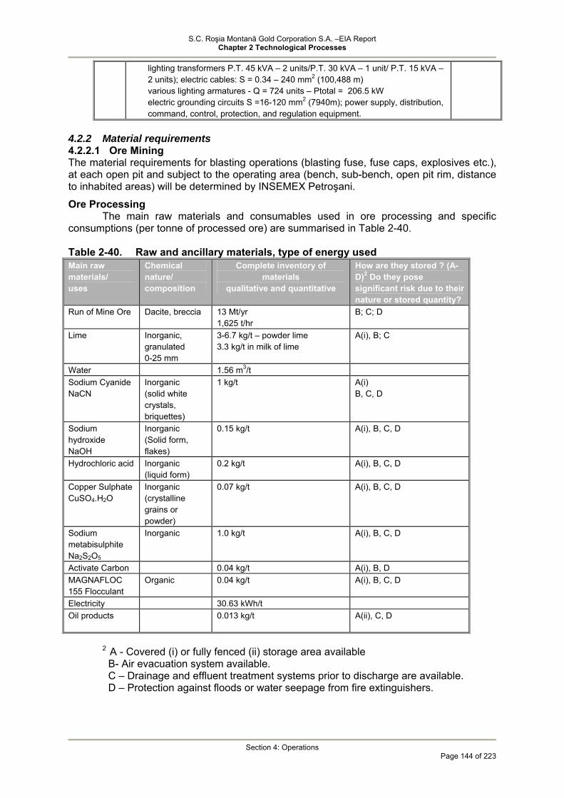
S.C. Roşia Montană Gold Corporation S.A. –EIA Report Chapter 2 Technological Processes
Section 4: Operations
Page 144 of 223
lighting transformers P.T. 45 kVA – 2 units/P.T. 30 kVA – 1 unit/ P.T. 15 kVA – 2 units); electric cables: S = 0.34 – 240 mm2 (100,488 m) various lighting armatures - Q = 724 units – Ptotal = 206.5 kW electric grounding circuits S =16-120 mm2 (7940m); power supply, distribution, command, control, protection, and regulation equipment.
4.2.2 Material requirements 4.2.2.1 Ore Mining The material requirements for blasting operations (blasting fuse, fuse caps, explosives etc.), at each open pit and subject to the operating area (bench, sub-bench, open pit rim, distance to inhabited areas) will be determined by INSEMEX Petroşani.
Ore Processing The main raw materials and consumables used in ore processing and specific
consumptions (per tonne of processed ore) are summarised in Table 2-40.
Table 2-40. Raw and ancillary materials, type of energy used Main raw materials/ uses
Chemical nature/ composition
Complete inventory of materials
qualitative and quantitative
How are they stored ? (A-D)2 Do they pose significant risk due to their nature or stored quantity?
Run of Mine Ore
Dacite, breccia 13 Mt/yr 1,625 t/hr
B; C; D
Lime Inorganic, granulated 0-25 mm
3-6.7 kg/t – powder lime 3.3 kg/t in milk of lime
A(i), B; C
Water 1.56 m3/t Sodium Cyanide NaCN
Inorganic (solid white crystals, briquettes)
1 kg/t A(i) B, C, D
Sodium hydroxide NaOH
Inorganic (Solid form, flakes)
0.15 kg/t A(i), B, C, D
Hydrochloric acid Inorganic (liquid form)
0.2 kg/t A(i), B, C, D
Copper Sulphate CuSO4.H2O
Inorganic (crystalline grains or powder)
0.07 kg/t A(i), B, C, D
Sodium metabisulphite Na2S2O5
Inorganic
1.0 kg/t A(i), B, C, D
Activate Carbon 0.04 kg/t A(i), B, D MAGNAFLOC 155 Flocculant
Organic 0.04 kg/t A(i), B, C, D
Electricity 30.63 kWh/t Oil products 0.013 kg/t A(ii), C, D
2 A - Covered (i) or fully fenced (ii) storage area available B- Air evacuation system available. C – Drainage and effluent treatment systems prior to discharge are available. D – Protection against floods or water seepage from fire extinguishers.

S.C. Roşia Montană Gold Corporation S.A. –EIA Report Chapter 2 Technological Processes
Section 4: Operations
Page 145 of 223
4.2.3 Facilities (buildings, laboratories, storage areas) 4.2.3.1 Gate house
The gate house will be a multipurpose building which will include a security office, first-aid room, ambulance and fire truck garage.
4.2.3.2 Administration building
The administration building will be a one storey building, which will include: reception area, general office, canteen, washroom and mechanical equipment room.
4.2.3.3 Crib room and laboratory
It will be a two storey building. The ground floor will host the metallurgical and assay laboratories, AAS room, balances and screens room, sample preparation and gold refining room, environmental laboratory, sample receipt room, sample storage area, reagent and consumables storage area, thermal plant, change rooms for men and women and washroom. The first storey is directly connected to the processing plant and includes change rooms for mean and women, washroom, canteen, storage room for mechanical and electric spare parts, computer room, protocol and conference rooms.
4.2.3.4 Plant storage facility and workshop
The building will include a storage area and plant workshop. It is provided with a 15 t bridge crane, tool storage room, mechanical and electric workshops, carpenter's workshop, painting room, crib room, all located at the ground floor. The offices and conference room will be located at the upper floor.
4.2.3.5 Crib room and mine workshop
It will be a two storey building. The ground floor will host a workshop for 3 mobile/haul truck equipment fitted with 20t bridge crane, a workshop for smaller size vehicles fitted with 15t bridge crane, tool storeroom, canteen and washroom. The upper floor will host offices, reception, secure rooms, change rooms and washrooms with showers. The building will have its own fenced truck parking space.
4.2.3.6 Vehicle washing station
It will be a fully closed building provided with high pressure water systems with two wash ramps. Six high pressure water jets will be strategically located to ensure proper washing of trucks. As shown in the Ausenco Drawing 1418 – 16 – F 2226, wastewater from washing will be collected in a sump and pumped to an oil separator. Separated oil will be stored in 200l barrels and wastewater will report to the sewage system.
4.2.3.7 Explosives magazine and ANFO silos The explosives storage area (magazines and tanks) will be located south-west of Cârnic and Cetate open pits, on the right side of the access road connecting the processing plant and TMF dam. An Ammonium Nitrate-Fuel Oil (ANFO) mixture will be the primary blasting agent, supplemented by the use of emulsion (slurry) type explosives
Relevant details will be presented in the documentation under development by INSEMEX Petroşani.
4.2.3.8 Communication and Information Technology
A fibre optic link will be extended from the current termination at Gura Rosiei up to the plant site. This will become the primary method of communication for the Project. Hardware and wiring will be provided for a local area network connecting all workstations throughout the Roşia Montană site with up-to-date technologies. Business systems, including mine planning, maintenance, inventory control, and accounting will be provided. A telephone system will provide for on site voice communication along with radios and cell phones. Phone call points and fax machines will be located inside the administration building, assay laboratory, substation guardhouse, elution control room, processing plant
S.C. Roşia Montană Gold Corporation S.A. –EIA Report Chapter 2 Technological Processes
Section 4: Operations
Page 146 of 223
control room, warehouses/workshops and mine workshop. The radio communication system will consist of stationary units, mobile units mounted onto vehicles, personal mobile units. The radio communication system will cover the following areas: open pits, TMF and processing plant and will provide separate frequency channels for:
• mining operations; • processing plant operations; • processing plant maintenance; • security. Having considered the particularity and complexity of the Rosia Montana Project
activities, an additional public address system will be provided with call points strategically located throughout plant areas, the workshops, warehouse and other ancillary facilities. In addition, a radio telemetry system will be installed to allow the remote control of TMF water recycling, water abstraction systems and water supply pumps. A main station will be located in the milling circuit to allow the remote control of receiving/transmission at:
• TMF reclaim pump; • drainage recycling pump; • ARD collection pumps; • fresh water intake pumps (Aries river) • servo-mechanism fresh water pumps Either a programmable logic controller (PLC) or a distributed control system (DCS)
automated control system will be installed in the process plant to control primary and auxiliary processes from a central location.
4.2.3.9 Site Security
Access to the mine and various plant areas will be restricted. The process plant area will be securely fenced with a manned gatehouse at the main entrance. Security staff will be provided on a continuous basis for overall site security as well as to provide protection during gold pours. Doré will be stored in a permanently secured and guarded vault until shipped off site.
The pump stations for the Cetate Mine and Waste Drainage Pond and the Secondary Containment Dam will be securely fenced and locked and will be subject to daily inspection.
All vehicular and footpath access routes which approach or give access to areas permitted for mining and site activity under the planning consents will be equipped with locked barriers and will be adequately signed with warnings to alert potential trespassers of physical dangers within the operations site and of site security for the protection of site equipment and machinery. Regular security patrols will take place during each working shift throughout the operations sites, including inspection of the integrity of all barriers to access and continued visibility of adequate warning signs.
4.2.3.10 Fire Protection
The fire prevention system will consist of sprinkler systems, detection devices, manually operated local alarm points, and alarm bells located in strategic locations. A central alarm panel will be located in the process plant control room, (which will be manned 24 hours per day).
Sprinkler systems will be provided in the following areas: • Electrical substations; • Refinery areas; • Compressor rooms; • Control rooms; • Storage areas, warehouses and maintenance shops; • Laboratories;
S.C. Roşia Montană Gold Corporation S.A. –EIA Report Chapter 2 Technological Processes
Section 4: Operations
Page 147 of 223
• Offices and washrooms; • Dry complex; • Reagent mixing areas; • Hydraulic lubrication units; and, • Reclaim tunnel and crushed ore conveyors. Firewater will be drawn from the fresh water tank. The Project area will be serviced
with a fire main and a number of hydrants. In addition, fire hose cabinets will be located so that all interior areas of buildings are within reach of a fire hose stream. Portable hand-held fire extinguishers will be provided throughout these areas and near exits.
4.2.4 Services 4.2.4.1 Water supply
The management of water in the process plant is designed to maximise recycling of process water and to minimise process water effluent beyond the plant boundary with an aim to minimise demand for fresh water. This management strategy corresponds to BAT related to process water reuse (according to Section 4.3.11.1 of the EU Reference Document on BAT for Management...in Mining Activities, March 2004). Fresh water will be required for:
• Reagent mixing; • Gland seal water of process pumps; • Cooling circuits; • Elution circuit; • Electro-winning; and, • Drinking and fire water.
4.2.4.2 Fresh Water Supply The plant site fresh water supply (to cover process water demand) will be abstracted
from Arieş River with the abstraction point and pumps located in a diversion point in proximity of Câmpeni.
Water demand from the Aries River, under the normal operations, is estimated to be approximately 238.2 m3/hour. Water is pumped via a 13.2 km process pipeline running alongside the Abrud River to Gura Rosiei and diverted alongside the Roşia Valley to a 170 m3 (ø=6 m, H=6 m) fresh water supply tank. Fresh water from the abstraction system is stored in a 40 m diameter and 11 m high tank (13,800 m3). This tank will provide a three-day water storage capacity for the plant operation and potable use, i.e. 12,000 m3 plus a dedicated reserve for fire-fighting, i.e. 3,000 m3.
The fresh water abstraction system includes three vertical pumps (Q=125 m3/h, H=310 m.h., P=188 kW) and 250 mm pipelines in total length of approximately 4560 m.
Fresh water is distributed within the processing plant through a process network consisting of 3 horizontal centrifugal pumps (Q=300 m3/h, H=40 m.h., P=55 kW ) and a system of pipelines with diameters ranging from 300 to 20 mm and total length of approximately 1645 m. Water is distributed directly to various feeding points within the process.
4.2.4.3 Drinking Water
The onsite demand of drinking water is approximately 120 m3/day (5 m3/hour). A softening and treatment plant for water abstracted from the Arieş River will be
provided to produce drinking water. The system will include the following equipment: • Fresh water filter; • Water softener; • Drinking water unit; and, • Chlorine mixer.

S.C. Roşia Montană Gold Corporation S.A. –EIA Report Chapter 2 Technological Processes
Section 4: Operations
Page 148 of 223
After filtration, water goes through the softener and is stored in a storage tank. The water softener capacity is 2093 m3/day. Fresh water is mainly used in the carbon stripping circuit within the gold extraction process. Fresh water demand for carbon stripping is approximately 81.3 m3/h A small portion of the fresh water (132 m3/day) is treated for drinking water. Drinking water treatment process includes: filtration, chlorination, UV treatment and other procedures required to produce good quality drinking water.
Drinking water is stored in a tank with ø = 6 m x 6 m and is distributed by means of two vertical rotary pumps and pipelines.
4.2.4.4 Industrial water
The proposed Roşia Montană processing plant will require a constant and reliable water supply. Processing and delivery of the tailings to the TMF will require approximately 1 tonne of water per tonne of ore.
It should be noted that the requirement per tonne of ore processed could be expected to vary in practice due to the variation in the hardness of ore, the moisture content, and ore mineralogy through the course of operations. However, in practise the withdrawal of water from the TMF will be governed by actual rainfall amounts within the catchment basin of the TMF. In addition, there is a need to help ensure that there is never less than a minimum acceptable volume in the decant pond to ensure that there is sufficient clean water to float the pump barge and keep the pump intakes clear of sediment.
The grinding circuit will receive a limited stream of fresh water as dust suppression spray on the new ore feed.
The mill solution tank is supplied with the recycled overflow from the CIL tailings thickener, and therefore contains recycled cyanide from the CIL process. The mill solution tank will also have a make-up supply from the process water circuit to cater for any shortfall in supply.
Water from TMF and ARD treatment plant will be pumped and stored in the process water tank (D=15 m, H=12.5 m). This water will be distributed as industrial water by gravity to the process feed points by way of pipelines. The process water demand is primarily covered by water recycled from the TMF pond. It is estimated that throughout the mine life and under normal weather and operating conditions, about 91 % of the process water will be sourced from the TMF and the remaining 9 % from the ARD treatment plant effluent.
A simplified water balance is shown in Exhibit 2.22 and the detailed Project water balance is shown in Exhibit 2.23.
The water in the plant will be split into multiple systems to control cyanide distribution within the plant, and to minimize the cost of the use of cyanide. Hence, the grinding section will use process water from the CIP tailings thickener overflow thus closing the circuit. Make-up water will be added, as required, from the tailings water reclaim system, from the Acid Rock Drainage (ARD) plant discharge or from the fresh water supply system. Make-up water to the process water circuit can be sourced from the freshwater circuit if no other sources are available. The fresh water demand is largely determined by a consistent requirement for reagent mixing, which is proportional to tonnage throughput, plus a variable requirement for make-up water to the process.
Fresh water (i.e., not recycled water) will be required for the effective operation of the elution circuit.
The water cooling systems for the process equipment are designed to work in closed circuit, and will be used at the SAG mill, ball mills and air compressors. The cooling water will be distributed by way of pipelines which will operate in closed circuit with a cooling tower. Fresh water treated with specific reagents will be used in order to avoid corrosion and deposition.
The distribution of process water within the processing plant is shown in Exhibit 4.1.8 (of Section 4.1. Water).
The water supply to the process plant, expressed as average flow rate over the life of the project, is summarised in Table 2-41.

S.C. Roşia Montană Gold Corporation S.A. –EIA Report Chapter 2 Technological Processes
Section 4: Operations
Page 149 of 223
Table 2-41. Fresh water supply to the process plant
Source Average m3/hr
(estimated over life of project) Recycled water from the TMF 1183.55
Treated effluent from industrial wastewater treatment
plant 76.15
Fresh water supply 207.4
Water from the storm water pond 14.9
The total water requirement for the operations area is calculated based on the annual tonnage of ore mined. The plant will operate 365 days per year, with continuous service of 24 hours per day, seven days per week.
4.2.4.5 Domestic wastewater
Given the average number of 680 people working on the Project site during operations, it results a quantity of 5 m3/hr of domestic wastewater. Domestic wastewater will be collected through the sanitary sewage system and treated in the sewage treatment plant. Treated water will report to the process water circuit. Resulting sludge, estimated at an annual quantity of 2059 kg will either be used in farming or directed to the transfer station (only as dehydrated waste).
The simplified and detailed site water distribution flowsheets are shown in Exhibit 2.23 and Exhibit 2.24, respectively.
4.2.4.6 Wastewater management General
Water management is a key component of the Project, which, if properly implemented, will allow the mine site to operate efficiently while minimising the environmental impacts to water resources. The management of water for the Project considers the natural hydrology, as well as the influences of past human activity. The Project is located within a region that is subjected to substantial seasonal variation in precipitation and run-off. In addition, the hydrologic balance is positive, meaning that more water falls on the site than will evaporate. The Project is also located within a region where mining has been carried out over some 2,000 years resulting in modifications to the natural hydrology and hydrogeology, and significant contamination of watercourses in the Project area.
Three fundamental water management strategies will serve to reduce potential impacts associated with mine operations: These strategies will include:
• Drainage control that will capture contaminated water associated within the Project area and divert water not significantly impacted by mining activities (Project Drainage Control);
• Reuse and recycling of treated and untreated site water to reduce the need for fresh water and the need to discharge treated water (Project Water Processing); and,
• Continual maintenance of the site water balance to help ensure that sufficient water is available for project process use while preventing an excessive build-up of water in the storage facilities (Site Water Management Strategy).
The site water balance is shown in Exhibit 4.1.5 (Section 4.1 – Water), amended/ March 2006.
Project Drainage Control
The proposed Project has the following site drainage objectives:

S.C. Roşia Montană Gold Corporation S.A. –EIA Report Chapter 2 Technological Processes
Section 4: Operations
Page 150 of 223
• To the extent practicable, divert run-off water not significantly impacted by mining activities away from areas where it may co-mingle with mining-impacted water and reduce the available water storage volume in site water control facilities;
• To protect structures, stockpiles and active areas (e.g., plant yard, offices, pits, etc.) from flood flows; and,
• To intercept and store contaminated run-off water for recycling within the mine process or for treatment for discharge into downstream surface water, of equal or better quality than set by regulatory consents.
Wherever practicable, diversion ditches will be constructed to minimise the volume of surface water entering the site and the water containment systems. These diversion ditches will be intended to convey water that is not significantly impacted by historical or proposed mining activities. The ditches will reduce the volume of clean water mixing with water requiring treatment, thus reducing the wastewater storage and treatment requirements. In addition, the diversion ditch water will help maintain the biological base flows in the creeks downstream of the Project.
Another function of the diversion ditches is to reduce the potential flooding of site facilities. The Project is located within hilly terrain and the proposed ditches around the pits, stockpiles, plant, and waste disposal areas will provide control of surface runoff except under extreme events. For the plant site, surface runoff will be directed to the plant storm water pond that will also act as a secondary containment system for the plant facilities.
The TMF is designed for total containment under all expected operational conditions. There is sufficient storage for extreme precipitation events in the TMF (i.e., Probable Maximum Precipitation event). Throughout most of the Project operational life there is enough available storage for multiple extreme events. Other water storage facilities are designed to store appropriate volumes of water under normal storm conditions. These facilities will include spillways designed to prevent facility failure under extreme events.
The Corna Valley TMF forms the largest containment and drainage control structure on-site. Water draining from much of the impoundment catchments will be collected and contained in the tailings decant pond. This will provide the major source of water for ore processing. Diversion channels in the upper portion of the basin will be constructed to collect and route un-impacted runoff water around the TMF.
Other smaller water management impoundments will be constructed to manage site water, as shown in Exhibits 2.3 to 2.6. These include:
• Cetate water impoundment and dam: the Cetate Dam will collect and impound acid rock drainage from the current site features, as well as possible new acid rock drainage runoff and seepage water from the Roşia Montană stream catchments. Much of the water collected by the impoundment will be drainage from historic underground mine workings via the 714 adit. During the later portions of the mine life when the bases of the pits are below the elevation of the 714 adit, the storage capacity will be used to store water pumped from the mine pits.
• The water impounded behind the Cetate Dam will be pumped to the wastewater treatment plant. A possible addition to this system may include installation of a valved plug in the 714 adit. This plug would allow for controlled release of water in the underground mine workings, or to prevent water impounded behind the Cetate Dam from backing up into the open-pits when these are developed below the 714-adit level.
• Roşia Diversion Channel and Diversion Channel Dike: diversion works will be constructed, to the extent practical, to direct clean water around the Cetate Waste Rock and Mine Drainage Pond to downstream of the Project area. These diversion works will divert the Roşia Montană Stream and unaffected runoff water from the north slope of the Roşia Valley to downstream of the Cetate dam.
• Cetate water impoundment and dam: will be constructed upstream of the tailings impoundment, immediately downstream from the Cîrnic Waste Rock Disposal

S.C. Roşia Montană Gold Corporation S.A. –EIA Report Chapter 2 Technological Processes
Section 4: Operations
Page 151 of 223
Site. The facility will be designed to collect possible acidic runoff from the waste rock and pump it to the wastewater treatment plant. This will prevent the water from mixing with the tailings pond water and impacting the reclaim water required for processing. This dam will be constructed at the onset of impacted drainage from the disposal site. Runoff collection ditches will be constructed on the downstream side of the waste rock disposal site to collect seepage and runoff and route it into the drainage pond. Diversion ditches will be constructed on the upstream side of the Cîrnic Waste Rock to divert water that has not contacted the waste rock around the facility. A spillway will be constructed in the containment pond embankment that will control the discharges from large storm events that will flow into the TMF Reclaim Pond.
Project Water Processing
Water treatment will be required at the site in order to reuse in the process (thus reducing the fresh water demand) and discharge site-impacted water to the environment In addition, a substantial portion of the water treatment capacity will be used to treat water impacted by the previous mining activities. Treatment will be required for the existing and new sources of ARD and to treat residual cyanide concentrations (post-detoxification) from the ore processing. These sources and the associated treatment technologies are key components of water management at the site and are described here. The sources and outflows from the wastewater treatment process are illustrated as Exhibit 2.22.
Site Water Management Strategy
The overall water management strategy contains all of the components previously discussed in this Water Management Section. The two watersheds, the Roşia Valley and Corna Valley watersheds were considered, along with operations during storm conditions and abnormally dry periods.
Roşia Montană Valley Watershed
The Roşia Montană Valley watershed will contain most of the mining operation. Figure 2.9 illustrates the primary components of the water management strategy during the operations phase. During normal operation water from undisturbed areas will be routed around the mining facilities and discharged to Roşia Creek, thus helping maintain base flow in Rosia valley and reduce volume of Project water requiring management. As the mining expands in the Roşia Valley, the location of the diversion ditches will be adjusted so that flows from active mining areas are excluded.
Figure 2.9 Rosia Valley water management during operation
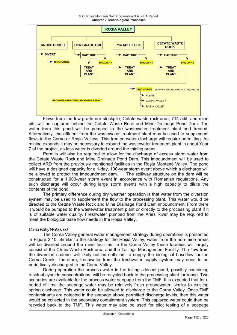
S.C. Roşia Montană Gold Corporation S.A. –EIA Report Chapter 2 Technological Processes
Section 4: Operations
Page 152 of 223
CETATE WASTE ROCK
CAPTURE
SPILLWAY TREAT
ARD PLANT
DISCHARGE (APPROVED DISCHARGE STANDARDS)
PLANT
CORNA VALLEY
ROSIA VALLEY
DIVERT
DISCHARGE
UNDISTURBED LOW GRADE ORE
TREAT ARD
PLANT
CAPTURE
SPILLWAY
714 ADIT + PITS
CAPTURE
SPILLWAY TREAT
ARDPLANT
ROSIA VALLEY
REQUIRES APPROVED DISCHARGE PERMIT
Flows from the low-grade ore stockpile, Cetate waste rock area, 714 adit, and mine
pits will be captured behind the Cetate Waste Rock and Mine Drainage Pond Dam. The water from this pond will be pumped to the wastewater treatment plant and treated. Alternatively, the effluent from the wastewater treatment plant may be used to supplement flows in the Corna or Roşia Valleys. This treated water discharge will require permitting. As mining expands it may be necessary to expand the wastewater treatment plant in about Year 7 of the project, as less water is diverted around the mining areas.
Permits will also be required to allow for the discharge of excess storm water from the Cetate Waste Rock and Mine Drainage Pond Dam. This impoundment will be used to collect ARD from the previously mentioned facilities in the Roşia Montană Valley. The pond will have a designed capacity for a 1-day, 100-year storm event above which a discharge will be allowed to protect the impoundment dam. The spillway structure on the dam will be constructed for a 1,000-year storm event in accordance with Romanian regulations. Any such discharge will occur during large storm events with a high capacity to dilute the contents of the pond.
The primary difference during dry weather operation is that water from the diversion system may be used to supplement the flow to the processing plant. This water would be directed to the Cetate Waste Rock and Mine Drainage Pond Dam impoundment. From there it would be pumped to the wastewater treatment plant or directly to the processing plant if it is of suitable water quality. Freshwater pumped from the Aries River may be required to meet the biological base flow needs in the Roşia Valley.
Corna Valley Watershed
The Corna Valley general water management strategy during operations is presented in Figure 2.10. Similar to the strategy for the Roşia Valley, water from the non-mine areas will be diverted around the mine facilities. In the Corna Valley these facilities will largely consist of the Cîrnic Waste Rock area and the Tailings Management Facility. The flow from the diversion channel will likely not be sufficient to supply the biological baseflow for the Corna Creek. Therefore, freshwater from the freshwater supply system may need to be periodically discharged to the Corna Valley.
During operation the process water in the tailings decant pond, possibly containing residual cyanide concentrations, will be recycled back to the processing plant for reuse. Two scenarios are available for the process water seepage from the TMF. It is expected that for a period of time the seepage water may be relatively fresh groundwater, similar to existing spring discharge. This water could be allowed to discharge to the Corna Valley. Once TMF contaminants are detected in the seepage above permitted discharge levels, then this water would be collected in the secondary containment system. This captured water could then be recycled back to the TMF. This water may also be used for pilot testing of a seepage

S.C. Roşia Montană Gold Corporation S.A. –EIA Report Chapter 2 Technological Processes
Section 4: Operations
Page 153 of 223
treatment system If the pilot system discharge meets permitted limits it could be discharged to the Corna Valley and become a permanent component of the water management system If it does not meet permit requirements, it could be recycled back to the TMF during system development. Development of a treatment system for the tailings seepage water is a key component to the long-term management of TMF water. This system will be an important component at closure and also for managing storm water accumulations in the TMF.
Three potential sources of ARD are present in the Corna Valley: the Cîrnic Waste Rock Pile, the tailings in the TMF, and the waste rock used in the TMF dam construction. The Cîrnic Waste Rock seepage will typically be pumped to the Roşia Montană Valley wastewater treatment system. However, if the water does not contain significant ARD, it may be discharged to the TMF decant pond. Because of how the TMF will be operated, weathering of the TMF tailings will be limited and should not generate any significant ARD. Saturated tailings will be placed at a rate that will limit the opportunity for oxidation. What little ARD that may be produced will be contained and recycled with the process water. The TMF dam will be constructed to the extent practical with waste rock with low ARD potential. If some ARD is generated it will be contained in the Secondary Containment System and either recycled to the TMF, or discharged through the pilot treatment system, if permit limits are met.
During large storm events, the water falling in the TMF watershed will be retained in the decant pond. The TMF has the ability to store a PMF event, and indeed multiple events during much of its operation. With the high amount of dilution associated with a large storm event, and the associated acceleration in cyanide degradation, the water quality may quickly become acceptable for discharge with concentrations below permit limits. The option then exists to discharge this water to maintain the planned TMF storage capacity. If concentrations remain above permit limits then the excess water may be handled by treating a portion in the downstream treatment system for seepage (the system can be designed for excess capacity) and by consumption in the ore processing. A portion of the wastewater treatment plant discharge would typically be used for the ore processing. To help consume the excess storm water, all of the water from the wastewater plant would be discharged.
Impoundments that are part of the TMF Secondary Containment System and Cîrnic Waste Rock seepage collection system will be designed to discharge during events exceeding a 1-day, 100-year storm event. In such situations, the Cîrnic collection pond would discharge to the TMF and the secondary containment system to the Corna valley. The Secondary Containment System would need to be permitted for this discharge.
Water management for the TMF during periods of prolonged dry conditions will consist of diverting storm water into the TMF reclaim pond, pumping back all seepage, and discharging all of the wastewater treatment plant water to the TMF. During these periods, the fresh water supply system would be required to maintain the biological base flow in Corna Valley.

S.C. Roşia Montană Gold Corporation S.A. –EIA Report Chapter 2 Technological Processes
Section 4: Operations
Page 154 of 223
CORNA VALLEY
DIVERT
DISCHARGE FRESH WATER
UNIMPACTED WATER ARD WATER
TMFTAILINGS
MONITORING NO PREDICTEDARD FROM TAILINGS
CARNIC WASTE ROCK
PUMP TOROSIA
OR
OVERFLOW TOTMF PONDRAINWATER MIXING
DISCHARGE
TREATMENT LAGOONS DISCHARGE
TMF DAMWASTE ROCK
RECYCLETO POND
OR
PROCESS WATER
RECYCLE TREATMENTDISCHARGE
SEEPAGE RECLAIM POND
NORMAL OPSRECYCLE
EXTREME RAINTREATMENTDISCHARGE
TREATMENT
ANEROBIC LAGOONS
AEROBIC LAGOONS
DILUTION ARD DISCHARGE
DISCHARGENEED REGULATORY APPROVAL AND DISCHARGE STANDARDS
Figure 2.10 Corna Valley water management during operation Table 2-42. Site pipelines
Pipeline Purpose Average Design m3/s
Pipe Length M
Fresh Water Supply Pipeline from Aries River
Fresh water supply for Project requirements 240 11.200
Cetate Wastewater Pipeline
Transports the water from the Cetate Drainage Pond to wastewater treatment plant
378 1.805
Cîrnic Wastewater Delivery
Transports the water from the Cetate Drainage Pond to wastewater treatment plant
48 2.120
Treated water release to Roşia Valley (pipeline or open channel from wastewater treatment)
Releases treated water from the wastewater treatment plant to augment base flows in the Roşia stream.
314 2.080

S.C. Roşia Montană Gold Corporation S.A. –EIA Report Chapter 2 Technological Processes
Section 4: Operations
Page 155 of 223
Pipeline Purpose Average Design m3/s
Pipe Length M
Treated water release to Corna Valley (pipeline from wastewater treatment to downstream of the secondary containment dam)
Releases treated water from the wastewater treatment plant to augment base flows in the Roşia stream. 20 4.900
Tailings Delivery Pipeline
Transports residue from Process Facility to Tailings Pond 2.274 5.200
Reclaim Water Pipeline
Transports water from TMF to the Process Water Tank at the plant 1.516 5.100
Secondary Containment Pond to the TMF
Pumps back the seepage from the TMF 114 1.200
(*) All flows are averages and assume a design factor of 1.2, i.e., 8,000-hour annual operation.
Characteristics of the principal collection and distribution systems are summarised
below.
Cetate Wastewater Pipeline Acid runoff from historical operation (including the Adit 714 runoff) and the new mine
will be captured in the Cetate drainage pond. The base flow in the Roşia stream will be maintained primarily by constructing a diversion canal that will collect and divert water not impacted by the new mining operations around the Cetate dam and discharge it into Roşia Creek. Initially, the 3.9 km diversion canal will drain an area of about 7.5 km2, which has not been impacted by recent mining. This represents about 70 % of the Cetate pond catchment. Hence, initially the base flows of the Roşia Stream downstream of the Cetate dam will only be affected to a minor extent by the construction of the dam.
The acid water captured in the pond will be pumped to the wastewater treatment plant, located in the processing plant. Due to the expected oscillations in the pond levels, the pumping station is anticipated to be located on a floating barge. The 300-mm pipeline will be buried along the access road to the plant, parallel with the fresh water supply pipeline.
Treated Water Discharge Conduits
Baseflow in Roşia and Corna Streams will be supplemented by release of treated water from the wastewater treatment plant or from the fresh water supply system when necessary. The release points will be downstream of the Cetate Dam and the TMF Secondary Containment System. Current baseflows have been estimated to be 18 l/s in the Rosia Valley and 7 l/s in the Corna Valley. These minima will be maintained by the diversion channels, release of treated water from the wastewater treatment plant, or from the fresh water supply system. The releases from the wastewater treatment plant will be increased as required to dispose of the project surplus water and the design capacity of the conduits leading to the Roşia Stream will be increased accordingly. Pipelines will be constructed to feed treated water discharge into graded conduits, which will be maintained by gravity flow from the discharge point from the wastewater treatment plant. Under extreme dry conditions, fresh water may be used to supplement the Roşia and Corna stream flow to maintain the biological baseflow.
Tailings Delivery Pipeline
Tailings from the processing plant will be pumped from the tailings pump box located at the processing plant to several discharge points at the TMF. The 5.2 km-long pipeline will be 800-900 mm in diameter and will generally follow the mine roads leading to the TMF. Suitable containment will be provided to control any occurrences of spillage. The solids content of the tailings being transferred to the TMF will be approximately 49 %.
S.C. Roşia Montană Gold Corporation S.A. –EIA Report Chapter 2 Technological Processes
Section 4: Operations
Page 156 of 223
4.2.5 Electricity An existing 110 kV overhead power line from Zlatna to Roşia Poieni operated by S.C.
Electrica S.A. bisects the project site, running from the south to the north. This line has the capacity to meet the existing demand in the region plus the anticipated Project needs. The existing line will be relocated around the western side of the Project site (to avoid crossing mine haul roads and mine waste rock disposal sites) and a new spur line will connect to the primary substation building at the plant site (see Exhibits 2.3 – 2.6, 2.8). Electrical power at the plant site will be based on a primary 20 kV voltage. Electric power will be distributed around the site at 20 kV (standard Romanian voltage), mostly via overhead lines, but with buried cables when appropriate.
The following works are required for the Project electricity supply: • construct one S110/20kV – of 63/80 MVA electrical substation and two 20/6kV –
of 12,5 MVA power transformers; • connect the substation to the electricity system (the existing 110 kV loop) -
double in-out connection, from the no.1 and no. 2 power line circuits Zlatna – Processing Plant;
• enhance the distribution capacity for emergency situations and improve power supply reliability to the existing facilities.
Stand-by power generation will be provided locally for emergency operations of critical systems. 4.2.6 Access Roads
Access to the site via the national road system is shown in Exhibit 2.21. Only minor road building is required to link the plant site to the national road system. The access roads are suitable for servicing the Project, providing access from the major commercial and residential areas in the region.
Internal roads include: • Process plant site roads; • Service roads to the tailings pipeline, explosives storage area, water supply line
and overhead power line; and, • Mine haul roads. Vehicles will use the pit bench roads, pit development roads, semitrenches and main
haulage roads. In addition to these main access roads, service roads will be constructed to connect
the plant site, four open pits (Cetate, Cîrnic, Jig and Orlea), waste rock dumps (Cetate and Cîrnic) and the Corna TMF Dam (Exhibit 2.10).
The mine material haulage road for Cîrnic pit is located south of the Cetate and Cîrnic pits. This haulage road will provide main access to Cîrnic pit and south access to Cetate pit.
Cîrnic pit access road will extend by a branch that goes around the south-east rim of Cîrnic pit and will be the main haulage road for Cîrnic waste rock.
The Orlea pit mine material haulage road to starts from the processing plant site and goes north along the west rim of Cetate open-pit towards the Orlea pit site. This road will also provide access to the west and north parts of Cetate pit, to Orlea pit and to Cetate waste rock stockpile.
The Jig pit mine material haulage road branches off the Orlea haulage road, follows Roşia Valley in the north-west part of Cârnic pit and then goes up the northern slope of the valley, toward the Jig pit site.
The Corna TMF haulage road branches off the Cîrnic pit haulage road and goes south along the west side of Corna Vallley.
All main mine material haulage roads will have a minimum width of 30m to ensure safe driving on two traffic lanes of haul trucks. The roads will be covered with gravel and

S.C. Roşia Montană Gold Corporation S.A. –EIA Report Chapter 2 Technological Processes
Section 4: Operations
Page 157 of 223
maintained by sprinkling and compacting, in order to increase the productivity of the haul trucks, as well as to reduce the level of airborne particulate.
Annual transport capacities required during the Roşia Montană Project life will have to cover the requirement for mine material haulage as follows:
• transport of high grade ore from the open pits to the primary crusher; • first stage transport of low grade ore from the open pits to the low-grade ore
stockpile, to be further routed to the primary crusher; • transportation of waste rock to waste rock disposal sites.
4.2.7 Workforce A detailed list of jobs and job descriptions is being developed. An inventory of skills
available in the surrounding communities throughout the region is also being developed. The RMGC Human Resources Department will, based on the results of the survey, identify and train local people as well as implementing hiring policies with preference being given to local persons in cases where their attributes are equal. During the operational life of the Project, when special skills are unavailable locally and training is not practicable due to time constraints, suitably qualified personnel will be hired from outside the local area.
The total workforce required for the operations phase of the Project is expected to be around 680 persons of various skills and qualifications suitable for the Project activities.
4.3 Pollution Sources
4.3.1 Emissions 4.3.1.1 Atmospheric emissions Emissions from mining activities
The atmospheric pollution sources that will remain active throughout the life of the Roşia Montană Project:
Pollution sources: • suspended particles generated by mining, drilling/blasting, loading, unloading and
grading activities – mobile unducted sources; • exhaust gases: from internal combustion engines of drilling, loading, hauling and
grading equipment – mobile unducted sources; • blast-related gases – mobile unducted sources; The equipment used represents mobile air pollution sources. All pit ore mining activities are fugitive sources of dust and exhaust gases, as
described below: Fugitive emissions associated with: • drilling; • blasting, with associated emissions of dust and explosive escape gases: CO,
NOx, SO2. Fugitive dust emissions from mining and crushing of oversize material, stockpiling
and truck operating on the haulage roads; Exhaust gases containing NO, NO2, N2O, CO, CO2, SO2, CH4, VOCnm, organic
volatile compounds and heavy metal particles i.e. Cd, Cu, Cr, Ni, Se, Zn. Dust on haulage roads and similar emissions of exhaust gases from haul trucks
hauling ore to the processing plant, low-grade ore stockpile or waste rock stockpiles. Dust may be generated during ore mining activities and may contain various
concentrations of heavy metals such as: As, Cd, Cu, Cr, Ni, Se, Zn, etc. Sources associated with open-pit mining occur at ground level or very close to the
ground level, are relatively continuous, with variable emission rates, generally depending on the activity and weather conditions.
The only instantaneous source – lasting only for a few milliseconds – is blasting. Open pit sources are expected to have a point, surface and linear behaviour.

S.C. Roşia Montană Gold Corporation S.A. –EIA Report Chapter 2 Technological Processes
Section 4: Operations
Page 158 of 223
The detailed emission inventory was developed for the ore processing phases for years 8, 10, 12 and 14 as presented in Tables 4.2.12 through 4.2.15. Emission source parameters are summarised in Tables 4.2.16 through 4.2.19. Calculated concentrations for operational phase are presented in Section 4.2. AIR.
Given the disperse nature of the pit pollution sources - open spaces - and the amount of polluting activities to be carried out, during a set period of time, no additional systems for atmospheric pollutant collection and dispersion are anticipated.
Initial dispersion of pollutants will be limited, and will be initiated by upward air movements occurring near the ground level or, in case of pollutants released by mobile sources, by local turbulence generated by the movement of the source.
Blasting generates significant initial dispersal due to the impulse generated by the forces occurring during the explosion.
Open pit sources are expected to have a point, surface and linear behaviour. The concentrations of the source emissions in the open pit cannot be evaluated
because of their free, open and unducted nature. For this reason, they cannot be evaluated as per the requirements of M.O. 462/1993.
The following parameters must be taken into consideration when developing the inventory of emissions for the operational phase:
• maximum quantity of rock anticipated to be mined annually from the open pit; • full range of ore mining operations (e.g. drilling, blasting, crushing, handling and
transport) taking into consideration the maximum quantities to be mined; • number of drill rigs; • average surface area affected by blasting; • quantity of explosive used; • type of explosive; • total number of km covered by the haulage trucks and number of hours worked; • average haulage speed; • road length; • diesel fuel consumption for haul vehicles and other stationary and mobile
equipment; • work schedule at each open pit; • type of vehicle; • active areas exposed to wind erosion; • humidity; • average concentration of metal in dust. Measures for mitigating and preventing air pollution as a result of the mining
operations are described in Section 4.2. AIR, Table 4.2.101.
Emissions from mining activities Emissions associated to the operational phase for the processing plant The pollutant emissions which may influence atmospheric air may originate from
ducted or unducted sources, and will consist mainly of dust generated by: Ore transport, handling, storage and processing. Transport, storage and processing of ancillary materials and reagents. Transport, storage and handling of fuels.
1. Primary crushing and grinding The air polluting sources and specific pollutants related to this phase are the
following: Run-of-mine ore stockpile – open, free, unducted source, at ground level, partially
closed. Potential emission sources:
S.C. Roşia Montană Gold Corporation S.A. –EIA Report Chapter 2 Technological Processes
Section 4: Operations
Page 159 of 223
• Unloading of ore from trucks onto the stockpile platform. • Wind erosion on the active stockpile surface and on the stockpile platform. • Primary crushing – is associated with the following sources: • Unloading of ore from haul trucks into the dump hopper – unducted source; • Transfer of ore from the ore stockpile platform into the crusher by means of front end
loader – unducted source; • Ore crushing – unducted source; • Transfer of crushed ore onto the belt conveyor – unducted source; • Transfer of ore from the discharge belt conveyor onto the main belt feeding the
crushed ore stockpile – unducted source; • Crushed ore stockpile - potential air pollution sources are as follows: • Transfer of crushed ore to stockpile – unducted source; • Loading of crushed ore from stockpile onto the main belt conveyor feeding the SAG
mill – unducted source; • Wind erosion on the stockpiled ore surface – ground, unducted source.
Characteristic for the pollutant in the phases related to the ore primary crushing, transfer, unloading and loading in/from the crushed ore stockpile is its wide dimensional range.
Another specific air pollution within this site is generated by the operation of the mobile equipment in the area (haul truck, front end loaders).
Grinding circuit – air pollution may be generated by the following sources: An unducted source represented by natural ventilation which may generate airborne particulates in the closed grinding circuit – the source of these particulates may be the transfer of lime powder onto the belt conveyor feeding the SAG mill. Mill ore feed, transfer of gravel from the SAG mill to the transport circuit, storage, sizing, transfer to the SAG mill belt feeder. The pollutant related to the grinding circuit is represented by particulates with a wide dimensional range. It should be noted that a small quantity of dilute cyanide solution will be added in the grinding circuit. Because the alkaline environment is kept under strict control by pH monitoring, the potential for HCN occurrence and release to environment is highly unlikely. In addition, the continuous addition in the SAG mill of cyanide solution and crushed ore will result in the reduction of the emission of solid particulates from the grinding circuit.
The determination of the pollutant emissions was based on the following considerations:
• Maximum quantity of ore hauled from open pit and unloaded onto the stockpile - 2000 tons/hr;
• Average quantity of ore stockpiled – 300,000 t (120,000 m3) taking up a surface area of approximately 7,500 m2;
• Average quantity of ore transferred to the primary crusher, crushed and conveyed to the crushed ore stockpile ranges between 2,500 tons/hr and 3,450 tons/hr (assuming the crusher is fed with 50 % ore unloaded directly from the haul trucks and 50 % ore from the stockpile);
• Average quantity of ore transferred from stockpile ranges between 1,600 tons/hr and 2,300 t/hr;
• Quantity of ground lime added onto the SAG mill belt feeder ranges between 5 t/hr and 11 t/hr;
• Average quantity of ore transferred to the SAG mill ranges between 2,000 tons/hr and 3,000 t/hr;
S.C. Roşia Montană Gold Corporation S.A. –EIA Report Chapter 2 Technological Processes
Section 4: Operations
Page 160 of 223
• Quantity of pebble transferred to the pebble crushing plant and onto the SAG mill belt feeder ranges between 400 t/hr and 650 t/hr;
• Average quantity of ore transferred to the SAG mill ranges between 2,000 tons/hr and 325 t/hr;
• The following measures will be employed to mitigate dust generation: • Local dust control equipment comprising exhaust system, pneumatic ducts, dust
collection filter at the crushing circuit. • High pressure water jet systems, (efficiency - 96 %), located in the crusher
discharge bin and at the point of transfer of ore onto the main conveyor, in order to reduce airborne dust.
• Water jet sprinklers for coarse emission control (efficiency – 96 %) located at the three discharge points of crushed ore onto the SAG mill belt feed conveyor.
• The tunnel will be fitted with a system for evacuation of unpurified air, at a flow rate of 13,000 Nm3/h. Evacuation of purified air will be done through a 0.8 m diameter stack at 5 m above ground.
• Standard operating procedures regarding periodic maintenance of crushing and grinding equipment will be implemented.
• Local solid particulate emission control systems will be ensured. • Continuous addition of cyanide solution and crushed ore in the SAG mill will
result in the reduction of the emission of solid particulates from the grinding circuit.
• Keeping alkaline environment under strict control by pH monitoring avoids/reduces the potential for HCN occurrence and release to environment.
2. Recovery of precious metals
The previous metal recovery process involves two main stages: • Cyanide leaching, adsorption and thickening • Gold and silver recovery by desorption. Potential air pollution sources associated with metals recovery are as follows: Leaching tanks and tailings thickener – located outdoors. The maintenance of a
highly alkaline (pH 10.5 or higher) environment in the leaching tanks and tailings thickener is fundamental for an efficient recovery of metals from the crushed ore. This high pH value will significantly limit the formation and release of HCN into the atmosphere. However, evaporation of a certain amount of liquid, due to CIL tank agitation systems, is still possible at this location.
Additional pH monitoring systems and HCN alarms will be installed in order to maintain high pH values. The cyanide mass balance presented in Section 4.1 estimates a minimal cyanide loss through volatilization.
Acid wash and neutralisation columns – the transfer of the active carbon loaded with gold and silver cyanide complexes to the wet process outside the two systems. Trace or ultratrace quantities of HCN generated by the acid environment and released into the working enclosure will be evacuated by natural ventilation.
Elution columns –The pollutant sources associated to the elution columns will be represented by the two heaters supplied with LPG (liquefied petroleum gas) at a maximal hourly consumption rate of 2 x 450 kg/h = 900 kg/h. The heaters will be in service four cycles of 4.5 hours a day.
Exhaust gas from the two heaters will be collected and evacuated through separate stacks 30 meters high and internal top diameter of 1.0 meter. The released pollutants are specific for LPG which is considered “clean” for this process.
Carbon reactivation equipment – The carbon reactivation kilns will be powered with GPL fuel or electricity, according to the technical specifications file 1418-DS-008
S.C. Roşia Montană Gold Corporation S.A. –EIA Report Chapter 2 Technological Processes
Section 4: Operations
Page 161 of 223
Ausenco. The primary pollutant in this area is represented by carbon particles released during the transfer of dehydrated carbon to the reactivation kilns and during the transfer of reactivated carbon to the storage tanks.
The carbon reactivation kilns are fitted with separate local collection systems for polluted air, each with a flow rate of 1,600 Nm3/h. The systems are connected to a wet scrubber with 90 % control efficiency and air flow rate of 46,280 Nm3/h. The scrubber is also connected to other local air collection systems (including those related to electro-winning cells, slag crusher, mercury retort). Evacuation of purified air will be done through a 1.4 m internal diameter stack and 15 m high.
The carbon reactivation area is fitted with a mechanical ventilation system with an air flow rate of 6,200 Nm3/h through a stack with 0.6 meter internal diameter at 10 meters above the ground.
Electro-winning cells – Specific pollutants are represented by particulates with metal content and with traces of ammonia.
Each cell is fitted with a local installation for collecting of polluted air. Local collection systems from each cluster are connected to central collecting-evacuation installations with an air flow rate of 15,400 Nm3/h. The two central installations (from each electro-winning cells) are connected to the wet scrubber mentioned above.
Mercury retort – is fitted with a local installation for collecting-evacuation of air loaded with water vapours, air flow rate 2,600 Nm3/h. The installation is connected to the wet scrubber mentioned above. Based on the efficiency characteristics of the system used for mercury recovery and emission control, it is estimated that no mercury will be released into the atmosphere.
Smelting and casting of metals into ingots – Smelting of gold and silver will be performed in two electric induction furnaces, each having a capacity of 750 kg. Potential air polluting sources in this phase are represented by fine particles of mainly gold and silver oxides, oxides of other metals forming gold alloys in the smelting furnaces, and fine suspended particles from the dry environment around the slag processor and pulveriser.
The smelting furnaces are fitted with local installations for capture of air contaminated with fine particulates (gold and silver oxides, oxides of other metals – all generated by evaporation of metals and condensation in air), each with an air flow rate of 2,500 Nm3/h. These installations are connected to a scrubber (alkaline environment – NaOH solution) (BAT procedure). Air will be evacuated at a flow rate of 5,000 Nm3/h, through a stack with 0.6 m internal top diameter, at 12 m above the ground. The wet scrubber has a 90% efficiency.
The slag crusher and pulveriser are fitted with local collection installations for air with (mainly) metal particulates connected to a central installation with a flow rate of 9,700 Nm3/h. The central installation is connected to the same wet scrubber used by the air-trapping systems from carbon reactivation, electro-wining cells and mercury retort.
3. Emissions from auxiliary processes
Lime storage and handling. Lime is one of the most important reagents to be used in the process. It is used both
in solid form (lime powder) and as a hydrated lime slurry. The emission sources related to lime storage include the following: • Transfer of raw lime from transport vehicles to the reclaim feeders of the two lines
(average rate 2x150 tons/hr, maximum 2x300 tons/hr) – unducted, intermittent sources;
• Transfer of lime from reclaim feeders to the vibrating feeders (2x30 tons/hr) – unducted, intermittent sources;
• Transfer of lime from vibrating feeders to the high angle conveyor carrying the lime to the silos (2x30 tons/hr) – unducted, intermittent sources;
• Transfer of lime into the two silos (2x30 tons/hr) – unducted, intermittent sources fitted with emission control systems;

S.C. Roşia Montană Gold Corporation S.A. –EIA Report Chapter 2 Technological Processes
Section 4: Operations
Page 162 of 223
• Transfer of lime from Lime Silo No. 1 onto the Lime Feeder No. 1 (5.1-10.9 tons/hr) – unducted source;
• Transfer of lime from Lime Silo No. 2 to Lime Feeder No. 2 (0.6-6.0 tons/hr) – unducted source;
• Transfer of lime from Lime Feeder No. 1 into the hammer mill No. 1 – unducted source;
• Transfer of lime from Lime Feeder No. 2 into the hammer mill No. 2 – unducted source;
• Transfer of lime from hammer mill No. 1 onto the crushed lime belt conveyor (5.1-10.9 tons/hr) – unducted source;
• Transfer of lime from Lime Mill No. 2 onto the crushed lime belt conveyor (0.6-6.0 tons/hr) – unducted source;
• Lime Mill No. 2 - (0.6-6.0 tons/hr) – unducted source; • Lime hydration circuit (working in closed circuit with the ball mills and cyclone
clusters) – ducted source, with emission control system. • Lime silos are provided with emission control systems fitted with bag filters, 90 %
efficient. The lime slaking mill will be fitted with local collecting installation for pollutants, air
flow rate 5,000 Nm3/h, connected to a wet scrubber, 90 % efficient fitted with a sprinkler system which separates cleaned air and water loaded with lime dust which is evacuated by means of a ventilation system and recycled by gravity to the lime slaking mill. As shown in Exhibit 2.25, the scrubber is also connected to all local collection systems within the lime preparation circuit. The treated air from the scrubber will be evacuated through a stack with 0.4 meters internal top diameter, at 8m above the ground.
The belt conveyors will be encased and will not constitute sources of atmospheric pollutants.
Reagent Storage Facility The main reagents which represent potential air pollution sources within the storage
area are copper sulphate and sodium metabisulphite. Both sources are intermittent. The potential pollution sources are: • The copper sulphate mix tank, fitted with local collecting-evacuation system for
pollutants – ducted source, at an airflow rate of 1,000 Nm3/h. • The sodium metabisulphite storage tank, fitted with local collecting-evacuation
system for pollutants – ducted source, at an airflow rate of 1,000 Nm3/h. • The HCN storage tank and distribution installation, fitted with a scrubber
ventilation system (with NaOH solution) and 14 m high exhaust stack. The efficiency of this emission control system is 100 %.
Thermal Plant The pollutant mass flows rates for the stationary sources related to ancillary facilities
and activities (thermal plant, fuel storage area, backup power generator) were determined using the EEA/EMEP/CORINAIR 2000 and US EPA – 42, version 11.02.2004 (according to Section 4.2. AIR – Section 4.2.2.3).
The thermal plant is designed to heat the buildings and provide hot water for domestic use. The thermal plant will be equipped with a boiler of 10,500 kW thermal power. The boiler will operate on liquid fuel, with a maximum consumption of 927 kg/h (1.8 m3/h) that corresponds to the rated capacity.
During the cold season, to ensure additional heating of the buildings, the plant will operate at an average capacity of 43%, with 400kg/h (0.8 m3/h) consumption. The thermal plant is fitted with a 30 meter high exhaust stack, with an internal diameter of one meter for capturing and releasing exhaust gases.
S.C. Roşia Montană Gold Corporation S.A. –EIA Report Chapter 2 Technological Processes
Section 4: Operations
Page 163 of 223
The thermal plant will use low-sulphur liquid fuel, type 3 CLU LLF. Standard operating procedures regarding periodic maintenance of boilers will be
implemented. Fuel Storage Facility The fuel storage area represents a complex of ductless sources of VOC –
hydrocarbons specific to distilled oil products (diesel and gasoline – containing predominantly light hydrocarbons: butane, pentane, hexane. VOC emissions are generated by evaporation losses on:
• free areas within the fuel storage tanks site with emissions taking place through tank portholes;
• product handling: tank filling and fuel delivery to users. The plant site fuel storage facility will include one above-ground storage tank (~
800,000 litres) for diesel fuel and one above ground storage tank (~ 20,000 litres) for gasoline surrounded by a containment berm with capacity to hold 110 % of the volume of the largest tank. The storage tanks and the related fuel station will be provided with fuel vapour recovery systems, as per the provisions of GD 56/2001.
Gasoline will be supplied exclusively by tankers fitted with fuel vapour recovery systems, at least 91 % efficient.
Standard operating procedures will be implemented to minimise petroleum product spills.
Backup Electric Power Generator The generator will have an installed power of 2200 kW and will be equipped with
diesel engine and NOx emission control system. The diesel fuel used will have a sulphur content below 1%.
Combustion products will be released through a 20 m high stack, with internal diameter of 0.8 m, exhaust rate of 48,500 m3/h and exhaust discharge speed of 26,8 m/s.
Due to its destination, the generator will operate only incidentally, in cases of emergency (main power supply failure) and for limited periods (for a few hours).
Mobile Sources
Mobile sources include: • Equipment operating at the low-grade ore stockpile; • Vehicles for supply/delivery which will visit the site; • Vehicles for workers transport at the processing plant site; • Equipment and vehicles used for ore handling and hauling.
The pollutant emissions generated by the plant site ancillary traffic are very low in comparison with those estimated for the main site traffic and for other mobile sources related directly to the operations.
Mitigation measures will require maintaining a wetted road surface to minimise potential emissions during dry season.
Standard operating procedures will be implemented to stop dust generating activities during strong wind conditions.
All operational equipment used on site will meet the strictest EU and/or Romanian emission standards for mobile and stationary equipment.
A maintenance and revision program for mobile and stationary equipment will be implemented, in order to ensure compliance with the regulatory standards.
Table 4.2.102 in Section 4.2. AIR, gives details on the emission control installations (gas treatment and discharge) as well as the air pollution prevention measures.
Monitoring activities and corrective/preventive actions are provisioned in the Air Quality Management Plan (ESMS Plans, Plan D) and Environmental and Social Monitoring Plan (ESMS Plans, Plan P).

S.C. Roşia Montană Gold Corporation S.A. –EIA Report Chapter 2 Technological Processes
Section 4: Operations
Page 164 of 223
4.3.1.2 Water Pollutant Emissions
A potential exists for run-offs from open pits (walls, benches) and waste rock stockpiles to be acidic. Such run-offs will be collected by means of drainage trenches and dewatering pits, and pumped to the wastewater treatment plant.
During the operation of industrial installations, potential spillages may occur such as: tailings slurry from the pump feeder tanks, effluents from wetting systems related to screen and Trommel filters or from other equipment operating in wet environments. Other accidental spills of process fluids may also occur due to damaged connecting pipes or from pump stuffing boxes which are left with insufficient pressure in the gland water system.
In order to prevent water pollution, all industrial buildings with wet processes will have concrete platforms with adequate downgradients, cut-off channelling and containment sumps to collect process drainages or accidental spills. All industrial facilities within the plant site will be similarly designed. Containment sumps will be fitted with pumps for collected drainages. Collected drainages will be directed to certain set points within the process, depending on the effluent quality, as described in the following paragraphs:
Grinding – Milling Section
All run-offs and circulating water from the milling circuit platforms will be collected into sumps and pumped back to the cyclone feeders. Such sumps and pumping systems are provided for the SAG mill, ball mills, cyclone clusters and screens (Exhibit 2.13).
Recovery of Precious Metals
Drainages from the cyanide installation platform will be directed and collected into sumps, and then pumped into the feeding tanks of each CIL circuit or to the feeding of the last CIL tanks, as shown in Exhibit 2.14 A/B.
Drainages from the acid wash columns area will be directed to a collection sump, from where the fluids will be pumped to the feeding tank of the tailings pumps, and then to the TMF (Exhibit 2.15).
Drainages from the elution-stripping columns platforms will be directed to a collection sump and then pumped to the tailings pumps and TMF, or to the CIL feeding tanks (Exhibit 2.15).
Drainages from the electro-winning cells will be collected and then pumped to the CIL reactor feeder (Exhibit 2.16).
Drainages from the carbon reactivation area will be collected and then pumped to the feeder tank of the sizing screen located in front of the reactivation kilns (Exhibit 2.24).
Drainages from the mercury retort area will be collected and then pumped to the CIL feeding tanks (Exhibit 2.31).
Tailings Thickening and Detoxification Facility
Drainages from the tailings thickener platform will be collected and then pumped to the slurry feed of the thickener (Exhibit 2.17).
Drainages from the detoxification agitators will be pumped to the detoxification feed basin (Exhibit 2.17).
Drainages from the tailings pumps feed tank will be collected and pumped back into the same basin (Exhibit 2.17).
Lime Storage and Handling
Drainages from the processing of powder lime and lime slurry will be collected in separated sumps and then pumped to tailings pump feeding tank and TMF (Exhibit 2.25).
Sodium Cyanide Mixing and Storage
Drainages from this area will be collected in a sump and then pumped into the cyanide solution surge tank (Exhibit 2.24).
Sodium Hydroxide Mixing and Storage

S.C. Roşia Montană Gold Corporation S.A. –EIA Report Chapter 2 Technological Processes
Section 4: Operations
Page 165 of 223
Drainages will be collected and pumped to the surge tank feeding the tailings thickener surge tank (Exhibit 2.25).
Copper Sulphate Mixing
Drainages from this area will be collected and then pumped back into the copper sulphate surge mixing tank (Exhibit 2.26).
Sodium Metabisulphite Mixing
Drainages from this area will be collected and then pumped back to the sodium metabisulphite surge mixing tank (Exhibit 2.26).
Flocculant Mixing
Drainages will be collected and then pumped to the feed tank of the tailings thickener, prior to detoxification (Exhibit 2.28).
The increase in workforce during the operational period will require the increase of the domestic water volume produced on site. Mitigation measures concerning the environmental impact include the building of a Domestic Wastewater Treatment Plant. As a result, during the entire life cycle of this plant, the treated domestic effluents will either be recycled in the process or discharged in the TMF. Discharge to the environment is not envisaged, therefore the potential impact is low.
For the plant site, surface runoff will be directed to the plant storm water pond located in the north-northwest part of the plant site that will also act as a secondary containment system for the plant facilities. The decant water from this pond will be pumped to the tailings detoxification reactors within the detoxification circuit of the tailings discharged from the CIL tanks. 4.3.1.3 Pollutant Emissions on SOIL/SUBSOIL
The impact on soil and subsoil is specific to the mining methods applied, and will materialise in:
• loss of land as a result of open pit development – mining of ore reserves; • loss of land as a result of waste rock stockpile development; • loss of land as a result of access and connecting road development; • landslides resulting from inobservance of engineering design, especially in the
case of waste rock stockpiles; • accidental spills of petroleum products as a result of leaking tanks or repair works
carried out in undesignated and inappropriate spaces; • landfilling of domestic and industrial waste in undesignated places. Current sources of soil pollution in the Project area relate to the waste rock stockpiles
from past mining activities. These deposits contain a number of chemical constituents that can affect the environment, soils and agricultural production, such as cadmium, copper, manganese, zinc, nickel and aluminium.
During the operational phase, soil may be contaminated as a result of accidents, fuel spills (gasoline, oils, lubricants). Another pollution source is inadequate storage, outside approved sites, of waste from explosive packaging.
No potential sources of entomological, parasitological, microbiological or radiation pollution will develop as a result of the proposed development.
Dust emissions generated by the ore haul vehicle traffic. Accidental spills of chemical reagents, contaminated process water or petroleum
products (diesel fuel, oil grease etc.). Mineral processing chemicals stored and used at the plant site will include sodium cyanide, granular active carbon, hydrated lime, copper sulphate, sodium meta-bisulphate, sodium hydroxide, and hydrochloric acid.
Pipe leakage, including spills from tailings detoxification and ARD treatment areas. The following measures will be applied to prevent/reduce the accidental
contamination of soil:
S.C. Roşia Montană Gold Corporation S.A. –EIA Report Chapter 2 Technological Processes
Section 4: Operations
Page 166 of 223
• Processing plant areas will be built on bermed concrete pads. The perimeter will be confined to direct run-offs and storm water to the site collection pond Water collected in the pond will then be pumped, depending on its quality, either to the Wastewater Treatment Plant or to the TMF.
• Pipeline leak detection systems and automatic shutdown systems for the process plant tailings pumps will be installed.
• Draining systems to direct spilled fluids to sumps and water-oil separators will be installed, in order to prevent impact on soil and underground water in case of accidental spills.
• The area will be organised in such a manner as to confine any accidental pollution and to minimize any adjacent impacts.
• Fuel and oil storage and distribution area will include oil and petroleum storage tanks, and separate raw oil/grease storage tanks. The tanks will be surrounded by a containment berm (secondary containment system) with capacity to hold 110 % of the volume of the largest tank, in order to retain any accidental spill.
• The pipe system will be checked periodically to identify any wear/damage and to avoid developments that might impact the environment. Materials and pipe types will be chosen in such a way as to allow operation in the given climatic conditions over the entire life cycle of the Project.
All operational equipment used on site will meet the strictest EU and/or Romanian emission standards for mobile and stationary equipment. A maintenance and revision program for mobile and stationary equipment will be implemented, in order to ensure compliance with the regulatory standards.
4.3.1.4 Noise and Vibration
The potential noise and vibration sources during the operational phase of the Project are related to the following activities and have transitory and stationery characteristics:
• Local and access roads (background noise); • Blast tests, drilling and blasting in open pits; • Drilling, excavation and loading in open pits; • Loading and unloading of ore, waste rocks and low-grade ore; • Loading and unloading of aggregates, top soil for required remediation activities
(after year 10); • Circulation of vehicles for transport of equipment, spare parts, fuel, waste and
other materials inside the Project area; • Operation of process equipment (such as: crushers, belt conveyors, SAG mill, bal
mills, pumps, compressors and other installations and equipment); • Testing and operating portable and/or emergency (backup) power generators; • Vehicle traffic related to workers and visitors transport; • Sirens, alarms and other warning auditory signals. The sources are generally represented by stationary equipment located on
construction sites, linear noise sources related to vehicle traffic, point noise sources related to blasting. Such sources will be active during day and night time, during 16 years.
Exhibits 4.3.6, 4.3.7, 4.3.8 and 4.3.9 (Section 4.3 Noise and Vibration) present the conservative prediction models for noise generated by stationary equipment, linear sources related to vehicle traffic and background noise produced by major activities during the operational phase. These results suggest that the noise and vibrations impact from cumulated sources, on receptors outside the industrial protection zone will be of short duration.
Noise and Vibration Mitigation Measures

S.C. Roşia Montană Gold Corporation S.A. –EIA Report Chapter 2 Technological Processes
Section 4: Operations
Page 167 of 223
The noise and vibration mitigation measures will be BAT as specified in Table 4.3.5, Section 4.3 Noise and Vibrations.
The measures proposed to reduce the noise and vibration impacts associated with the Project consist of a combination of the following measures:
Engineering measures: sound insulation for the buildings at the process plant site etc;
Institutional control implementation by establishment of protection zones, installation and imposing of speed limits for vehicles, suitable safety equipment for employees as per the health and safety program defined by the RMGC Occupational Health and Safety Plan.
Implementation of adequate control techniques and procedures such as maintenance and repairing schedule for the major equipment and machinery to ensure that sound emissions comply with the normal operational limits;
Management Controls, active engagement of the public and other external factors in the identification and resolution of noise and vibration issues through the communication mechanisms defined in the Public Consultation and Disclosure Plan (ESMS Plans, Plan K) and the procedures for corrective and preventive actions described in the Roşia Montană Project Environmental and Social Management Plan (ESMS Plans, Plan A).
Long-term monitoring of the noise and vibration impact on the workforce, sensitive structures, potentially sensitive fauna species and human receptors in the vicinity of the project’s industrial protection zone boundary.
Workplace Noise and Vibration Monitoring
The noise and vibration mitigation measures will be BAT as specified in Table 4.3.5, Section 4.3 Noise and Vibrations (page 32-33).
The Seismic Study is under development by INSEMEX Petroşani.
4.3.2 Waste The following categories of waste will be generated during the mining and ore
processing activities and connected activities within the Roşia Montană Project: Municipal or similar waste • non-hazardous (biodegradable, packaging waste); • slurry from the wastewater treatment plant; • non-inert demolition waste; Production waste
• hazardous production waste; • non-hazardous production waste; • waste generated by medical activities.
Details on the onsite waste management are presented in Section 3.0 WASTE.
4.3.3 Rehabilitation measures in the event of temporary suspension of operations RMGC will take all statutory and reasonable measures in line with policies, guidance
and BAT to protect public safety and minimise environmental impacts, if mining operations are in a condition of temporary suspension. Temporary suspension means the planned or unplanned suspension of operations with protective measures (including continuous monitoring) in place. Under such circumstances efforts will be focussed toward returning the mine to normal operational conditions at the earliest time. The periods of temporary suspension of operations are typically determined by a long-term unfavourable change in the economic conditions reducing the long-term viability of the mining operation.
In the event of a temporary suspension of operation, RMGC will notify appropriate government agencies. Although in such circumstances RMGC would have the full intention

S.C. Roşia Montană Gold Corporation S.A. –EIA Report Chapter 2 Technological Processes
Section 4: Operations
Page 168 of 223
of resuming operations as soon as possible, a temporary suspension could conceivably entail a lengthy period when the circumstances leading to the interruption in operations are outside of RMGC control.
The following minimum rehabilitative measures will be implemented as necessary for the Roşia Montană Project in the event of a temporary suspension:
• reasonable measures will be taken to restrict access to the site and buildings and other structures to authorised persons only;
• mine openings that are potentially dangerous will be closed-off against uncontrolled and unauthorised access;
• electrical systems will be protected from uncontrolled and unauthorised access; • mechanical and hydraulic systems will be shut down and secured where
possible; • physical, chemical, and biological monitoring programs will be continued; • contaminated effluents will be controlled; • waste management systems and sites and petroleum products, chemicals and
waste will be made secure; • portable cyanide tanks will be returned to the manufacturer; the cyanide handling
systems in the cyanide storage and processing areas will be flushed and any residual cyanide detoxified as noted in the RMGC Cyanide Management Plan;
• explosives will be secured, disposed of, or removed from the site; and • waste rock and overburden stockpiles and tailings, water and other impoundment
structures will be maintained in a stable and safe condition. 4.3.3.1 Tailings Management Facility (TMF)
Ongoing work on the TMF embankment will be completed to the extent that it remains in a stable and safe condition during any temporary suspension period. Depending on the period in which the suspension occurs, work on the TMF could continue to be performed to provide additional storage capacity.
The TMF and SCD will be monitored for physical integrity and remedial measures will be implemented as required. Seepage collected in the SCD pond will continue to be pumped to the reclaim pond at the start of the temporary suspension period. Since reclaim water will not be drawn off the TMF pond during a temporary suspension, there will be a build-up of water within the TMF from the recycling of the water back from the secondary containment pond and direct precipitation. The TMF will be monitored for remaining capacity. In addition, the water quality of the SCD pond and the TMF Pond will be monitored for heavy metals and residual cyanide. If residual cyanide levels are reduced to or below surface water discharge standard, then waters could be pumped to the waste water treatment plant for treatment of metals, Sulphate and Calcium and then discharged in either the Roşia or Corna valley drainages, consistent with plant operations during ore processing. Alternatively the passive treatment system downstream of the SCD could be used to treat seepage water, if the system is already operational at the time of temporary suspension. This water will be discharged directly to the Corna Valley drainage provided that it meets water quality requirements. 4.3.3.2 Waste Rock Stockpiles Ongoing work on the Cârnic and Cetate waste rock stockpile, including re-contouring, will be completed to the extent that the waste rock stockpiles remain in a stable and safe condition during any period of temporary suspension. If initiated, progressive rehabilitation on the lower lifts of the waste rock stockpile will be completed to the extent possible. Run-off from the waste rock stockpiles will continue to be collected in their respective run-off collection ponds and pumped to the wastewater treatment plant. As the process plant
S.C. Roşia Montană Gold Corporation S.A. –EIA Report Chapter 2 Technological Processes
Section 4: Operations
Page 169 of 223
demand for water will be curtailed, the plant outflow will be discharged to the Corna and Roşia creeks in accordance with the approved discharge permits. 4.3.3.3 Open Pits During a period of temporary suspension, access to the open pits will be secured to prevent unauthorised access. Safety signs will be erected around the pit to warn trespassers of the potential danger. Internal pit roads will be blocked with lockable gates or by the placement of berms or other physical barriers. Water will continue to be pumped from each of the open pits and directed to the wastewater treatment plant to maintain the pits as a hydraulic sink for the area. 4.3.3.4 Cetate Water Catchment Dam and Pond The Cetate Water Catchment Dam and pond will be maintained with any impounded water being directed to the wastewater treatment plant for treatment prior to release to the environment. 4.3.3.5 Wastewater Treatment The wastewater treatment strategy during a period of temporary suspension will be to continue to operate the wastewater treatment plant to treat water from the open pits, run-off from the waste rock stockpiles, the plant site, the TMF/SCD and the Cetate Water Catchment Dam pond prior to release to the environment. 4.3.3.6 Sludge Management Sludge generated by the wastewater treatment plant will be fluidised to the extent necessary to enable it to be pumped to the TMF Basin. 4.3.3.7 Miscellaneous Facilities The miscellaneous facilities in the plant area, as well as the mining machinery and equipment, storage tanks, and other facilities will be maintained in a stable and safe condition. 4.3.3.8 Site Water Management The onsite water management strategy during a period of temporary suspension will be to avoid build-up behind impoundments. This will be achieved through a system of collecting and treating impacted water prior to release to the environment, and collecting and releasing un-impacted directly to the environment. Specifically, diversion channels around the Cetate impoundment and the TMF will collect and route un-impacted surface water past these retention structures for discharge into the Roşia and Corna Valleys respectively. Water collected in the structures listed below will be pumped to the ARD treatment plant, processed and discharged:
• Cetate Waste and Mine Drainage impoundment; • the TMF impoundment basin; • Secondary Containment Dam impoundment; and • Cârnic Wastewater Collection Pond. Depending upon the phase of site development reached when the suspension
occurs, water may be routed through the semi-passive treatment systems located downstream of the SCD and Cetate Dam.

S.C. Roşia Montană Gold Corporation S.A. –EIA Report Chapter 2 Technological Processes
Section 5: Closure Phase
Page 170 of 223
5 Closure Phase
5.1 Activities
5.1.1 General approach The approach of the decommissioning and closure activities reflects the stage of the
engineering design as at October 2004. RMGC will develop appropriate closure and/or rehabilitation of the Project affected areas (e.g. processing plant facilities, TMF, access roads, inert waste landfill) such that, to the extent possible, this action will reflect the concept of sustainable use of available resources and meet the interests related to post-closure land use. RMGC gives consideration to the fact that the Mining Law 85/2003, Government Decision No. 1208 regarding approval of a Norm applying to Mining Law applications (2003) and Ministerial Order No. 273 regarding the approval of a mine closure manual (2001) stipulate that a mine closure plan must be developed for the proposed mine in advance of construction. Thus, the decommissioning and closure activities will be conducted in line with the latest version of the Mine Rehabilitation and Closure Management Plan for the Roşia Montană Project, developed as a first version under Plan J within the suite of plans that have been developed to support the Environmental and Social Management System. This plan represents a key element of the Roşia Montană Project Environmental and Social Management Plan (see Plan A of the Environmental and Social Management System) and will be updated subject to the changes in the control processes described herein. It is expected that the potential requirements and interests of the local community related to post-closure land use as well as other specific concerns of other stakeholders to change during the mine life cycle. Consequently, the Mine Rehabilitation and Closure Management Plan will be reviewed and updated periodically to be able to meet any such changes.
In the format in has been developed in, the decommissioning and closure phase will include the following:
The waste rock stockpiles will be regraded until a stable slope gradient is developed, which will allow placement of topsoil cover, stockpiled in the pre-construction phase.
The areas that were reprofiled and covered with topsoil will be seeded with native plant species.
The low-grade ore and topsoil stockpiles that will be used up at the end of the operational phase, will be scarified and revegetated with native species.
The downstream face of the TMF dam will be regarded, covered with topsoil and revegetated with native species.
The TMF pond will be regraded to facilitate run-off drainage and will be covered with topsoil prior to revegetation with native species including previous consolidation of the tailings.
The secondary containment dam and pond will be maintained in the Project post-closure phase until the regulatory standards concerning water discharge to environment are met; the secondary treatment system consisting of a series of semi-passive treatment bioreactive lagoons will be maintained as alternative solution regarding the compliance with quality regulatory standards provided for effluents discharged to environment.
The Mine Closure Plan will be implemented for details regarding mine rehabilitation (Jig backfilled, Orlea + Cîrnic partially backfilled, Cetate flooded) and will be updated periodically until the completion of the closure works.
Seepage from Cetate pit lake will be treated through the ARD treatment plant and then released to the Roşia valley. A secondary treatment system including a series of semi-passive treatment lagoons will be used to achieve all NTPA 001/2005 standards.
Diversion channels and trenches diverting water around disturbed areas will be constructed or upgraded.
Water will be managed in each of the two watersheds, as integral part of Project development.
S.C. Roşia Montană Gold Corporation S.A. –EIA Report Chapter 2 Technological Processes
Section 5: Closure Phase
Page 171 of 223
Process components or infrastructure elements which may be used by the local public authorities will be turned over to them along with all the operation and maintenance instructions. Alternatively, these components will be disassembled and sold or recycled, to the extent possible. Inert materials may stay on site or will be disposed of at an approved facility.
Closure activities will not have an impact on the Project protected zones. To the extent possible, the workforce employed for closure works will be recruited
from the operations personnel. The ecological restoration and rehabilitation activities will commence as from mid
mine life-cycle. As soon as certain stockpiles or roads are no longer used for operational purposes, ecological rehabilitation works will be initiated. These works will include regrading and covering with topsoil, should this prove required, followed by placement of topsoil and revegetation. The general sequence of the ecological rehabilitation activities is illustrated in Exhibits 2.5 – 2.7. These exhibits indicate the site layout in years 14, 16, 19 and 21 and also present an estimate of the areas to be rehabilitated after each stage.
5.1.2 Closure of mining operations
Explosives: will be returned to the supplier or, if this not possible, will be disposed of by a licensed contractor. Inventory control in the final years of operation will be implemented to reduce the quantity of explosives/chemicals remaining at closure. The explosive storage magazines will be decommissioned and fences and safety barriers will be removed. Explosive mix tanks will be cleaned and removed from the Project site for recycling as scrap. The area of the former explosive magazine will be graded and revegetated.
Mine mobile plant : Upon closure of mining operations only the equipment used in the decommissioning and closure activities in accordance with the purpose and scope of the respective activities will be kept from the mine mobile plant (e.g. excavators, front end loaders, haul truck, drilling rigs, bulldozers, graders and other categories of motor driven ancillary equipment). All end-of-life equipment will be transferred to other mining operations or sold. Equipment having no sale value will be sold for scrap.
Aggregate quarries (Şulei and Pârâul Porcului): In addition to the open pits where ore will be extracted, there will be two additional small pits (La Pârâul Porcului and Şulei) where aggregate will be obtained during the construction phase and as required through the life of the Project. The majority of the aggregate will be obtained during site construction with smaller amounts mined through the life of the Project. These pits will be developed in rock types (andesite and sandstone) that do not generate acid rock drainage, and therefore do not require any special closure considerations. However, berms will be placed around the perimeter of the pits in conjunction with signs to warn people of steep slopes.
Waste Rock Stockpiles: As per the current planning once mining is closed in Cîrnic pit (approximately in year 9), waste rock from other pits will be deposited here. All other quantities of waste rock generated will be stockpiled in two sites (Cetate and Cîrnic waste rock stockpiles), as shown in Exhibit 2.4.
A one-metre constructed layer of durable dacite will underlay the disposal sites and will serve as a drainage blanket. During operations, the run-off from the Cetate Waste Rock Disposal Site, which lies in the Roşia Valley, will be directed to the Cetate Waste Rock and Mine Drainage Pond. The collected wastewater will be pumped to the wastewater treatment plant for treatment prior to release into the local streams. Likewise, the collection pond for the Cîrnic Waste Rock Disposal Site will be retained and the collected water will continue to be directed to the Cetate pond or directly to the wastewater treatment facility.
Both waste rock stockpiles will be reprofiled to facilitate placement of a topsoil layer. The resultant final slopes maintain the overall 2.5H:1V slope with approximately 5 metre wide benches. As waste rock is being deposited during operations, the rehabilitation of this facility will be restricted until the last operational years when modifications will be made to allow regrading of the lower benches on each stockpile. Once a raise stage is completed, the slopes and benches will be regraded and covered with soil to reduce seepage and give a
S.C. Roşia Montană Gold Corporation S.A. –EIA Report Chapter 2 Technological Processes
Section 5: Closure Phase
Page 172 of 223
durable sublayer for development of vegetation. At closure, the Cîrnic waste rock stockpile will also be regraded to prevent seepage and allow run-off water to be directed to an impoundment and further to the Cetate waste rock and mine drainage dam or directly to the wastewater treatment plant, as shown before.
The testing program that aimed to quantify the ARD generation potential completed in the last years for RMGC by the independent MWH consultants, indicated that the waste rock fraction without acid generating potential or with low acid generating potential accounts for 61.4% of the waste rock (i.e., clearly dominating the geochemical characterisation), while material rated "likely" or "possibly" ARD generating potential accounts for 38.6%.
Overall, there is a net neutralising potential of the waste rock material which will be placed on waste rock facilities or backfilled into the open pits. RMGC will implement a waste segregation strategy. The ARD generating waste rock will be deposited in the centre (middle) of the stockpile or on the bottom of the pits to be backfilled. The pits will be covered with NAG waste rock. For the segregation of the PAG rocks (potentially acid generating) a mobile laboratory will be installed during the open pit operations, which will conduct geotechnical segregation tests. These tests start once drilling is conducted and should be finalised before loading the resulting ore.
The main conclusion relevant to the waste rock seepage quality predictions drawn from the geochemical testing program is that it is likely to have the characteristics of a neutralised ARD, with neutral pH, low concentrations of heavy metals but elevated contents of Sulphate, Calcium, Magnesium and TDS. With the waste rock segregation strategy and the placement of infiltration-reducing cover systems of end-dumped PAG parts of the waste rock facilities, the seepage is very unlikely to need treatment after closure.
For the NAG (non-acid generating) material and portions of the waste rock dumps where PAG material is stack-dumped and "encapsulated" by NAG material, design criteria for the cover systems are as follows:
• prevention of inadvertent access to the wastes • support of vegetation • improvement of visual appearance • prevention of dust blown off the wastes • erosion control. The minimum thickness for achieving the design criteria for NAG material is 30 cm,
consisting of the following: • 10 cm topsoil • 20 cm subsoil of clayey silt Additionally, for the PAG material which is end-dumped separately without
encapsulation by NAG material, the design criteria additionally include the following: • minimisation of water infiltration into the wastes • minimisation of oxygen entry to the wastes. To achieve these additional design criteria, the cover must be significantly thicker,
and possess sufficient long-term stability of its hydraulic and gas transport properties. Based on international experience, adapted to the climatic conditions, the following
Store & Release Cover (SRC) complemented by a layer of low oxygen diffusion is proposed. This is comparable to similar cover systems across the EU.
• 10 cm topsoil • 80-140 cm subsoil of clayey silt • 30-40 cm subsoil of compacted clayey silt as an oxygen barrier. Due to compaction, the oxygen barrier maintains a high pore saturation and thus
effectively inhibits oxygen diffusion (oxygen diffusion is highly dependent on the saturation of soil pores with water).
The use of water-saturated oxygen barriers as part of a cover is BATxxiii.

S.C. Roşia Montană Gold Corporation S.A. –EIA Report Chapter 2 Technological Processes
Section 5: Closure Phase
Page 173 of 223
Long-term stability of the oxygen barrier can be guaranteed if frost cracking, root penetration and other long-term perturbation effects are safely precluded.
5.1.3 Closure of processing activity 5.1.3.1 General Considerations
The majority of the buildings, facilities or structures that do not involve a significant amount of excavation works will be removed at closure or prior to closure, depending on the foreseen land use. The specific measures to be implemented for such structures or facilities and which will aim to minimize or remove long-term impact to environment are described hereinafter.
Processing plant site and ancillary facilities Inventory control will be implemented to ensure that the stockpiles of crushed and uncrushed ore are used up at the cessation of operation of the plant. The process reagent or process substance stock will be monitored to ensure that these are used up and that no additional quantities of such substances are supplied during closure. Soils at the plant site (including the soil under the plant surface water run-off collection pond and under the hazardous waste temporary storage facility) will be checked for contamination. In the event that contaminants are identified, they will be remediated in situ or disposed of off-site at an approved licensed disposal facility in compliance with the Roşia Montană Project Waste Management Plan (see Plan B within the suite of plans that have been developed to support the Environmental and Social Management System).
With the exception of the wastewater treatment plant or other process facilities that will be turned over to local authorities, depending on the future site use, other plant site facilities such as the fences, buildings, and structures will be removed or demolished. Mobile structures will be removed, sold or recycled. The major equipment inside the buildings will be removed for salvage and structures and foundations will be demolished to ground level. In accordance with the Waste Management Plan, structural materials will be salvaged for re-use or sale where appropriate. Domestic waste will be disposed of and stored in approved off-site waste facilities. Remaining inert materials will be disposed into an own inert material landfill, covered with a soil layer, and the area revegetated. All hazardous waste, including waste remaining from the temporary hazardous waste storage facility will transferred to an approved waste facility. Waste from foundations and concrete bays will be demolished to ground level, the respective areas will be covered with a soil layer, reprofiled and re-vegetated. All other end-of-life facilities with exposed areas of soil will be graded, if required, and re-vegetated.
Stationary Process Equipment Stationary process equipment, such as the crusher SAG and ball mills, will be removed from their foundations and sold to appropriate salvage outlets. Non-salvageable machinery and equipment will be checked to ensure that all fluid compartments are drained and the contents disposed of in an approved facility, according to the Waste Management Plan. The equipment will then be removed from the Project site sale, for scrap or disposal at an appropriate waste disposal facility.
Storage tanks and ancillary piping systems Careful inventory control will be implemented to minimise the quantities of reagents in storage tanks at the end of the mine’s operational life. The transportable cyanide storage tanks will be returned to the supplier for continued use; prior to removal and recycle all tanks and systems in the cyanidation circuit will de detoxified in accordance with the Cyanide Management Plan (Plan G within the suite of plans that have been developed to support the Environmental and Social Management System). Other remaining stocks of chemical products will be returned to the supplier or, if this not possible, will be disposed of by a licensed contractor. The diesel fuel, gasoline and lubricant tanks and dispensing systems may continue to be used, if deemed worthwhile, in the early years of closeout during which the covers are being installed and major earthworks are being carried out. The advantage of maintaining these tanks and dispensing systems will be to realise the benefits of existing infrastructure and to minimise the potential for accidental spills and pollution.
All storage tanks will be decommissioned in accordance with all applicable environmental and safety regulations. This includes the use of personal protective and safety
S.C. Roşia Montană Gold Corporation S.A. –EIA Report Chapter 2 Technological Processes
Section 5: Closure Phase
Page 174 of 223
equipment, air quality and off-gas monitoring, draining/transferring of tank contents, removal of any residues in containment structures, cleaning, cold or hot cutting of tanks, and removal by a licensed hauler to an approved landfill. Many of the tanks that were fabricated on site, including the CIL tanks and thickeners, will be cut up into scrap metal for removal (after detoxification, drainage and cleaning). Soils below storage tanks will be sampled and tested to confirm there is no residual contamination below each facility.
All decommissioning work will be performed by trained personnel, in accordance with standard workplace health and safety procedures as noted in the Occupational Health and Safety Plan, as well as Emergency Preparedness Plan (Plan I within the suite of plans that have been developed to support the Environmental and Social Management System). Work will be carefully planned, sequenced, and scheduled so that functional installations are properly and safely segregated from those areas that will be subject to disassembly. Particular care will be taken with regard to the use of portable and stationary ventilation systems, respiratory protection devices and other personal protective gear, as well as lockout/tagout procedures so that electrical equipment or machinery will not be inadvertently energised during disassembly. Work areas will be strictly delineated via temporary fencing, warning panels, visual and acoustic signalling and warning devices, or other appropriate means. Care will be taken to minimise the accumulation of debris that could endanger workers engaged in further disassembly or demolition activities. At disassembly, all connectors and fasteners will be sorted by size as necessary to support potential future reassembly. The disassembly sequences for major equipment items will, in general, be the reverse of the assembly order. Heavy parts will be strapped, chained, or bolted to wooden pallets or skids to prevent inadvertent rotation and to facilitate forklift handling and truck loading operations. Major equipment items and ancillary equipment will be sorted by function, placed on a bermed concrete pad, washed with detergents and/or solvents, and assessed for wear or damage. All drained waste oil or lubricants, washwater, and spent solvents will be captured, segregated, and accumulated in tanks (double-walled or provided with bermed concrete secondary containments) for proper disposal in accordance with the Waste Management Plan ((Plan B within the suite of plans that have been developed to support the Environmental and Social Management System). Depending on their disassembled condition, all decommissioned equipment items will be sold for beneficial reuse or for their scrap or recycling value.
Concrete rubble will be transported to the Inert Waste Landfill or (if permitted by the current approved version of the Waste Management Plan and/or the Mine Reclamation and Closure Plan, may potentially be used as backfill material in the open pits. Insulation material will be segregated for potential beneficial re-use or (depending on type) disposal as inert or municipal waste in accordance with Waste Management Plan requirements. No asbestos insulation will have been permitted in the construction of the process plant or its ancillary facilities.
The demolition of concrete (simple and/or reinforced) and masonry structures may also be assisted by means of explosives, should this be permitted by the current and approved version of the Mine Reclamation and Closure Plan or by the regulations in force. All explosives assisted demolition will be carried out in accordance with the current version or successor to Ministry of Work and Social Protection Order No. 838/1997, “Specific work safety standards concerning the storage, transport and use of explosive materials”.
The decommissioning of the process plant area will be divided into six major operations:
• decommissioning of the crushing plant and the crushed ore stockpile; • decommissioning of the milling, classification and gravitational concentration
plant; • decommissioning of Carbon-in-Leach, carbon stripping, electrowinning and
smelting plant; • decommissioning of reagent management area, excluding cyanide detoxification
plant;

S.C. Roşia Montană Gold Corporation S.A. –EIA Report Chapter 2 Technological Processes
Section 5: Closure Phase
Page 175 of 223
• decommissioning of ancillary installations, buildings and industrial structures • decommissioning of cyanide detoxification (DETOX) plant
Important note:
Some of the decommissioning activities may be scheduled and conducted in parallel, except that the cyanide detoxification plant will remain operational until all other process plant areas have been decommissioned.
Decommissioning/demolition of all structures will comply with the provisions of applicable closure-phase regulations. Such regulations will be defined in the Project’s current register of regulatory requirements (see Section 3.2 of the RMGC Environmental and Social Management Plan) and may include the current versions or successors of the following:
• technical prescriptions for “Specific work safety standards for underground mining of ferrous, non-ferrous, rare, radioactive and non-metalliferous ores” – Ministry of Work and Social Protection – 1998;
• Romanian State Standard STAS 1125/1 – 1981 – welding of metals; • Romanian State Standard STAS 10564 – oxygen torch cutting of metals; • P 54 – 80 – technical instructions concerning sectional steel structures; • PE – 119 – 1982 – work safety standards for electric installations; • general norms for fire prevention and extinction, approved by Ministry of the
Interior Order No. 775/1998; • Decision No. 678/1998 concerning the assessment and sanction of the
contravention’s related to fire prevention and extinction; and • technical norms for the design and building of structures – fire protection,
P118/1999.
5.1.3.2 Decommissioning of crushed ore stockpiling area Electromecanic installations and equipment
Major equipment items used in installations and equipment expected to be used in crushing operations, crushed ore storage, and reclamation from the crushed ore stockpile include the following:
Major equipment: gyratory crusher; conical crushers; oversize crusher; apron feeders; weighing devices; belt conveyors; metal detectors.
Ancillary servicing, control, and automation equipment is expected to include the following:
• Simple cranes (manual and mechanical hoists), electrical hoists, bridge cranes and other hoisting devices;
• compressed air equipment for the gyratory and conical crushers; • process circuits for spills evacuation, including centrifugal electric pumps, fittings,
pipes, elbows and valves. • wetting systems, climatisers and dust control equipment (e.g. exhaust systems,
ducting, bag-house filters), fire suppression systems; • electric power, command, automation, and lighting systems including: thriphase
power transformer, lighting transformers, various electric cables, lighting armatures, electric grounding circuits, power supply, distribution, command, control, protection, and regulation equipment, etc.
• critical fraction metal silo, metal structures connecting various process equipment and bins for collection of various materials, etc.
Upon carrying out the decommissioning of installations and equipment that make up the primary crushing circuit and of those used for storage, reclaim and transport of crushed

S.C. Roşia Montană Gold Corporation S.A. –EIA Report Chapter 2 Technological Processes
Section 5: Closure Phase
Page 176 of 223
ore from the crushed ore stockpile area it is imperative that all technical and organisational measures are taken in accordance with the technical specifications of each piece of electromechanical equipment and in compliance with the technical supervision and safety instructions provided in the applicable laws and based on the decommissioning design report.
Buildings and industrial structures
Decommissioning/demolition of industrial structures related to the ore crushing plant and stockpiling area of the Roşia Montanã processing plant will generally follow the following sequence:
The following operations will be completed for concrete (simple and/or reinforced) and masonry structures:
• dismantling of internal metallic structures (e.g. walkways, hand rails, platforms, etc.) by dismounting or by oxy-acetylene or arc cutting of reinforcing or support elements;
• removal of metal shrouds or shields by dismounting or by oxy-acetylene/arc cutting;
• removal of metal sheathing and roofing; • removal of metal-framed doors and windows; • disassembly of structural steel beams and joists (e.g. pillars, beams, bars, plates,
support structures, etc) by dismounting or by oxy-acetylene or arc cutting of reinforcing or support elements;
• demolition of concrete vertical walls; • demolition of cut-off walls or berms made of concrete slabs or blocks via
jackhammers or picks mounted on an excavator arm or other hydraulic equipment
• stripping of topsoil within the site and adjacent areas; • resulting rubble will be disposed of to the Inert Waste Landfill or may potentially
be used as backfill material in the open pits. The decommissioning works will be conducted in the following sequence: I. Decommissioning/demolition of buildings may commence only after the completion
of the following decommissioning works: dismantle, loading and disposal off site of electro-mechanic installations and equipment.
II. The first step once the electro-mechanic installations and equipment are decommissioned will be the decommissioning/demolition of buildings and service facilities located within the buildings.
III. The second step once the decommissioning/demolition of buildings and service facilities located within the buildings is completed will be the decommissioning/demolition of structural steel and external elements of the buildings.
After the completion of the decommissioning/demolition of the process plant buildings and removal offsite of all resulting materials, the gained land will be ecologically rehabilitated.
5.1.3.3 Decommissioning of milling, classification and gravitational concentration
plant Electro-mechanic installations and equipment
The major installations and equipment for the milling, classification and gravitational concentration plant are the following:
Major equipment: SAG mill D = 11000 x 5250 mm; ball mills D = 6700 x 11000 mm; Trommel screens at each mill; cyclone clusters 12 x Ø650 mm;
Ancillary equipment:

S.C. Roşia Montană Gold Corporation S.A. –EIA Report Chapter 2 Technological Processes
Section 5: Closure Phase
Page 177 of 223
• Simple cranes (manual and mechanical hoists), electrical hoists, bridge cranes and other hoisting devices;
• ventilation equipment and climatisers, including: ventilators, air conditioning and wetting unit, electric heaters, pipes, valves, measuring and control devices, etc.
• process circuits for fluids conveyance and spills evacuation, including various electric vertical and horizontal centrifugal pumps, tanks, distributors, fittings, pipes, elbows and valves.
• fire suppression systems; • electric power, command, automation, and lighting systems including: thriphase
power transformer, lighting transformers, various electric cables, lighting armatures, electric grounding circuits, power supply, distribution, command, control, protection, and regulation equipment, etc;
• metal structures connecting various process equipment, containers for collection of various materials.
Upon carrying out the decommissioning of installations and equipment that make up the milling, classification and gravitational concentration plant it is imperative that all technical and organisational measures are taken in accordance with the technical specifications of each piece of electromechanical equipment and in compliance with the technical supervision and safety instructions provided in the applicable laws. Buildings and industrial structures
The operations for decommissioning/demolition of the buildings made of structural steel, concrete masonry, simple and reinforced concrete structures as well as the sequence of these operations is described under Decommissioning of the crushed ore stockpile area.
After the completion of the decommissioning/demolition of the process plant buildings and removal offsite of all resulting materials, the gained land will be ecologically rehabilitated.
5.1.3.4 Decommissioning of Carbon-in Leach, carbon stripping, electro-winning and
smelting plants Electro-mechanic installations and equipment
The major installations and equipment for Carbon-in-Leach, carbon stripping, electro-winning and gold and silver smelting flowsheet are the following:
Major equipment: thickener (D = 50.000 mm, d = 11.800 mm); vibrating screen; KEMIX intertank screen (S = 12 m2); CIL tanks (D = 18,000 x H = 20,000 mm); cylinder screen (R = 1,200 mm); vertical centrifugal pumps (D = 250 mm); elution columns (D = 2,200 x H = 12,000 mm); heat exchangers (heat transfer Q = 3,660 kJ/s; 2,880 kJ/s); fluid electric heater (P = 5,764 kW); carbon regeneration kilns Q = 700 kg/h; horizontal centrifugal pumps; filter press (L = 1,200 x l = 1,200 mm, 42 chambers); vibrating screens; induction furnace Q = 750 kg; mercury retort V = 0.3m3; slag jaw crusher Q = 400 kg/h; press filter (L = 800 x l = 800 mm, 18 chambers); electro-winning cells (S = 0.84 m2 cathode area, N = 22 pcs.); centrifugal pumps; tower scrubber D = 1,067 x H = 4,025 mm; GEMINI 250 concentration table.
Ancillary equipment:
• simple cranes (manual and mechanical hoists), electrical hoists, bridge cranes and other hoisting devices;
• compressed air and ventilation systems, including ventilators, electric compressors, electric heaters, pipes, fittings, measuring and control devices, etc;
• process circuits for fluids conveyance and spills evacuation, including various electric pumps, tanks, distributors, fittings, pipes, elbows and valves;
• fire suppression systems;

S.C. Roşia Montană Gold Corporation S.A. –EIA Report Chapter 2 Technological Processes
Section 5: Closure Phase
Page 178 of 223
• electric power, command, automation, and lighting systems including: thriphase power transformer, lighting transformers, electric cables, lighting armatures, electric grounding circuits, power supply, distribution, command, control, protection, and regulation equipment, etc;
• metal structures connecting various process equipment, containers for collection of various materials.
Upon carrying out the decommissioning of installations and equipment that make up the Carbon-in-Leach, carbon stripping, electrowinning and gold and silver smelting plants it is imperative that all technical and organisational measures are taken in accordance with the technical specifications of each piece of electromechanical equipment/installation and in compliance with the technical supervision and safety instructions provided in the applicable laws.
Buildings and industrial structures
The operations for decommissioning/demolition of the buildings made of structural steel, concrete masonry, simple and reinforced concrete structures as well as the sequence of these operations is described under Decommissioning of the crushed ore stockpile area.
After the completion of the decommissioning/demolition of the process plant buildings and removal offsite of all resulting materials, the gained land will be ecologically rehabilitated.
5.1.3.5 Decommissioning of reagent management area, excluding cyanide
detoxification plant Chemical reagents used in the ore processing flowsheet are: lime (CaO), sodium
cyanide (NaCN), sodium metabisulphite (Na2S2O5), caustic soda (NaOH), flocculant, copper sulphate (CuSO4.5H2O), hydrochloric acid (HCl), oxygen (O2)
The primary installations and equipment in the reagent management area are the following:
Primary equipment: ball mill (D = 1,800 mm x L = 3,000 mm), vibrating screens – 2 units, vibrating feeder (l = 812 mm x L = 2.134 mm); belt conveyor (B = 1.000 mm x L = 6.100 mm); cyclone cluster (2 x 150 mm).
Ancillary equipment:
• simple cranes (manual and mechanical hoists), electrical hoists, bridge cranes and other hoisting devices;
• ventilation systems consisting of: ventilators, pipes, fittings, measurement and control devices, etc.
• process circuits for fluids conveyance and spills evacuation, including various electric pumps, tanks, distributors, fittings, pipes, elbows and valves.
• fire suppression systems; • metal silos; • power supply for equipment, control, automation and lighting: these have been
included in terms of items and quantities in the facilities described above; • metal structures connecting various process equipment, containers for collection
of various materials, etc. Given that the installations and equipment described above are similar, to a great
extent, from a design and functional standpoint, with those equipping the ore processing circuits, their decommissioning will follow the steps and technical and safety instructions described in the previous sections.
Buildings and industrial structures The operations for decommissioning/demolition of the buildings made of structural
steel, concrete masonry, simple and reinforced concrete structures as well as the sequence of these operations is described under Decommissioning of the crushed ore stockpile area.
S.C. Roşia Montană Gold Corporation S.A. –EIA Report Chapter 2 Technological Processes
Section 5: Closure Phase
Page 179 of 223
After the completion of the decommissioning/demolition of the process plant buildings and removal offsite of all resulting materials, the gained land will be ecologically rehabilitated.
5.1.3.6 Decommissioning of ancillary installations, buildings and industrial
structures The primary components and equipment to be decommissioned include the
following: • Simple cranes (manual and mechanical hoists), electrical hoists, bridge cranes
and other hoisting devices; • Compressed air, climatisers and ventilation systems, consisting of electric
compressors, ventilators, climatisers, piping systems, fittings, measurement and control devices, etc.
• process circuits for fluids conveyance and spills evacuation and delivery of tailings to TMF including various electric pumps, tanks, distributors, fittings, pipes, elbows and valves, etc.
• Fire suppression systems; • Sanitary facilities, administration and laboratory equipment; • Back-up power generator, power supply for equipment, control, automation and
lighting units; • Chlorination and treatment plant ensuring the water demand for potable use; • Metal structures connecting various process equipment, containers for collection
of various materials, etc. Given that the installations and equipment described above are similar, to a great
extent, from a design and functional standpoint, with those equipping the ore processing circuits, their decommissioning will follow the steps and technical and safety instructions described in the previous sections.
Accordingly, categories of works similar in terms of structure and technical and safety instructions with those described in the previous sections are provided for decommissioning/demolition of the buildings and industrial structures presented herein.
After the completion of the decommissioning/demolition of the process plant buildings and removal offsite of all resulting materials, the gained land will be ecologically rehabilitated.
5.1.3.7 Decommissioning of cyanide detoxification (DETOX) plant
Apart from general handling, cleaning, storage, and equipment condition assessment actions noted previously, all piping systems, tanks, and equipment items in the process plant that come in contact with cyanide compounds will be flushed and detoxified prior to decommissioning or disassembly, in accordance with the latest approved version of the Cyanide Management Plan and applicable regulatory requirements. The detoxification circuit within the reagent management areas of the process plant will be the final component to be decommissioned, in order to maintain an onsite capability for collection and detoxification of any potential spillage or residual cyanide compounds that may be encountered in the decommissioning of the carbon-in-leach (CIL) equipment or other systems and equipment. Detoxified effluent from the flushing process will be routed to the TMF pipeline and tailings deposition system. Further dilution and/or natural decomposition of residual quantities of cyanide resulting from deposition of detoxified flush water in the TMF will add a substantial additional margin of safety. If the TMF pond will be dewatered by pumping the water to Cîrnic or Cetate pits, the dilution and natural degradation effects will multiply.
Any residual cyanide that may be detected in the decommissioning of the detoxification plant itself will be neutralised using portable detoxification kits as noted in the Cyanide Management Plan and Emergency Preparedness and Spill Contingency Plan. All

S.C. Roşia Montană Gold Corporation S.A. –EIA Report Chapter 2 Technological Processes
Section 5: Closure Phase
Page 180 of 223
rinseate or cleanup compounds associated with detoxification plant decommissioning will be captured, placed in sealed containers, and transported to a licensed hazardous waste disposal facility.
The primary installations and equipment used in the reagent conditioning processes and the cyanide detoxification circuit include the following:
• cranes and other manual/electromechanical hoisting devices; • ventilation equipment and climatisers, including ventilators, piping systems,
fittings, and measuring and control devices; • processing circuits including different electrical pumps, tanks, and distributors
with valves, pipe, vanes and cocks; • fire suppression systems; • scrubbers; • metal silos; • various electric power, command, automation and lighting units; and • various metal ducts, chutes, bins, and material spill/debris collection devices. Given that the installations and equipment described above are similar, to a great
extent, from a design and functional standpoint, with those equipping the ore processing circuits, their decommissioning will follow the steps and technical and safety instructions described in the previous sections.
Accordingly, categories of works similar in terms of structure and technical and safety instructions with those described in the previous sections are provided for decommissioning/demolition of the buildings and industrial structures presented herein.
After the completion of the decommissioning/demolition of the industrial constructions and removal offsite of all resulting materials, the gained land will be ecologically rehabilitated.
5.1.3.8 Temporary hazardous waste storage facility decommissioning
The temporary hazardous waste storage facility will be decommissioned after the decommissioning of the process plant, explosives magazines, fuelling facilities, warehouses, machine shop areas, and other Project facilities that may involve the use or storage of hazardous materials, in order to provide storage capacity for any hazardous wastes that might be generated or encountered during decommissioning.
Decommissioning of the Temporary Hazardous Waste Storage Facility will involve the following steps:
• Shipment of all remaining hazardous wastes; • Review of facility logs and spill history; • Physical survey of pad, drains, sumps, and fenced area; • Removal/recycling/disposal of portable concrete barriers; • Removal/recycling of metal roofing; • Removal/recycling of roof poles; • Demolition of pads, drains, and sumps; • Removal/recycling of security fencing; • Regrading, placement of topsoil, and revegetation.
5.1.4 TMF Closure
At the end of operations period the Tailings Management Facility will be prepared for closure.
The preparatory work for TMF closure will primarily consist of modification of the tailings disposal system to achieve the final landform required by the cover system.
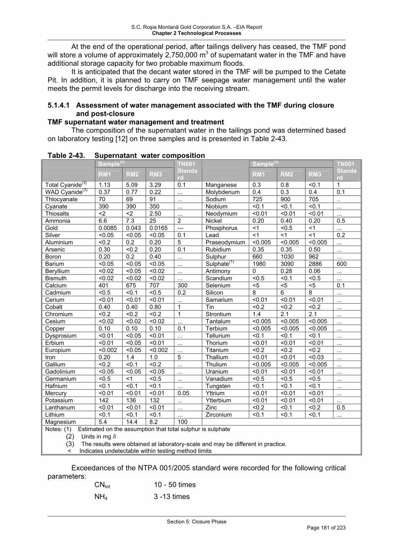
S.C. Roşia Montană Gold Corporation S.A. –EIA Report Chapter 2 Technological Processes
Section 5: Closure Phase
Page 181 of 223
At the end of the operational period, after tailings delivery has ceased, the TMF pond will store a volume of approximately 2,750,000 m3 of supernatant water in the TMF and have additional storage capacity for two probable maximum floods.
It is anticipated that the decant water stored in the TMF will be pumped to the Cetate Pit. In addition, it is planned to carry on TMF seepage water management until the water meets the permit levels for discharge into the receiving stream.
5.1.4.1 Assessment of water management associated with the TMF during closure
and post-closure TMF supernatant water management and treatment
The composition of the supernatant water in the tailings pond was determined based on laboratory testing [12] on three samples and is presented in Table 2-43. Table 2-43. Supernatant water composition
Sample(2) Sample(2) RM1 RM2 RM3
TN001 Standard
RM1 RM2 RM3
TN001 Standard
Total Cyanide(3) 1.13 5.09 3.29 0.1 Manganese 0.3 0.8 <0.1 1 WAD Cyanide(3) 0.37 0.77 0.22 ... Molybdenum 0.4 0.3 0.4 0.1 Thlocyanate 70 69 91 ... Sodium 725 900 705 .. Cyanate 390 390 350 ... Niobium <0.1 <0.1 <0.1 ... Thiosalts <2 <2 2.50 ... Neodymium <0.01 <0.01 <0.01 ... Ammonia 6.6 7.3 25 2 Nickel 0.20 0.40 0.20 0.5 Gold 0.0085 0.043 0.0165 --- Phosphorus <1 <0.5 <1 ... Silver <0.05 <0.05 <0.05 0.1 Lead <1 <1 <1 0.2 Aluminium <0.2 0.2 0.20 5 Praseodymium <0.005 <0.005 <0.005 ... Arsenic 0.30 <0.2 0.20 0.1 Rubidium 0.35 0.35 0.50 ... Boron 0.20 0.2 0.40 ... Sulphur 660 1030 962 ... Barium <0.05 <0.05 <0.05 ... Sulphate(1) 1980 3090 2886 600 Beryllium <0.02 <0.05 <0.02 ... Antimony 0 0.28 0.06 ... Bismuth <0.02 <0.02 <0.02 ... Scandium <0.5 <0.1 <0.5 ... Calcium 401 675 707 300 Selenium <5 <5 <5 0.1 Cadmium <0.5 <0.1 <0.5 0.2 Silicon 8 6 8 ... Cerium <0.01 <0.01 <0.01 ... Samarium <0.01 <0.01 <0.01 ... Cobalt 0.40 0.40 0.80 1 Tin <0.2 <0.2 <0.2 ... Chromium <0.2 <0.2 <0.2 1 Strontium 1.4 2.1 2.1 ... Cesium <0.02 <0.02 <0.02 ... Tantalum <0.005 <0.005 <0.005 ... Copper 0.10 0.10 0.10 0.1 Terbium <0.005 <0.005 <0.005 ... Dysprosium <0.01 <0.05 <0.01 ... Tellurium <0.1 <0.1 <0.1 ... Erbium <0.01 <0.05 <0.01 ... Thorium <0.01 <0.01 <0.01 ... Europium <0.002 <0.05 <0.002 ... Titanium <0.2 <0.2 <0.2 ... Iron 0.20 1.4 1.0 5 Thallium <0.01 <0.01 <0.03 ... Gallium <0.2 <0.1 <0.2 ... Thulium <0.005 <0.005 <0.005 ... Gadolinium <0.05 <0.05 <0.05 ... Uranium <0.01 <0.01 <0.01 ... Germanium <0.5 <1 <0.5 ... Vanadium <0.5 <0.5 <0.5 ... Hafnium <0.1 <0.1 <0.1 ... Tungsten <0.1 <0.1 <0.1 ... Mercury <0.01 <0.01 <0.01 0.05 Yttrium <0.01 <0.01 <0.01 ... Potassium 142 136 132 ... Ytterbium <0.01 <0.01 <0.01 ... Lanthanum <0.01 <0.01 <0.01 ... Zinc <0.2 <0.1 <0.2 0.5 Lithium <0.1 <0.1 <0.1 ... Zirconium <0.1 <0.1 <0.1 ... Magnesium 5.4 14.4 8.2 100 Notes: (1) Estimated on the assumption that total sulphur is sulphate
(2) Units in mg /l (3) The results were obtained at laboratory-scale and may be different in practice. < Indicates undetectable within testing method limits
Exceedances of the NTPA 001/2005 standard were recorded for the following critical
parameters: CNtot 10 - 50 times NH4 3 -13 times

S.C. Roşia Montană Gold Corporation S.A. –EIA Report Chapter 2 Technological Processes
Section 5: Closure Phase
Page 182 of 223
As 2 – 3 times Ca 1.3 – 2.3 times Mo 3 - 4 times SO4 3 – 5 times
In the early TMF closure phase the supernatant water has to be removed as quickly
as possible for the following reasons: • to stabilize the tailings surface where heavy equipment will be operated
(bulldozers) by surface remodelling and cover with soil. • to provide flooding of the Cetate pit so that potentially ARD generating rock
surfaces are submerged as soon as possible. The quality of the supernatant water in the tailings pond is similar to the pit water
quality except for the cyanide content. Therefore, measures should be adopted to prevent contamination of the pit water with cyanide.
There are two options to address this issue: • Actively treating the TMF decant water (i.e., removing cyanide) prior to discharge
to the pit. For this, the cyanide detoxification plant used during operations for treatment of tailings delivered to TMF will have to be modified. A feasible technology to meet the maximum permissible cyanide concentration as per NTPA 001/2005, i.e. 0.1 mg/l, may be a combination of the following:
• SO2/air technology employed during operations; • peroxide technology; • UV degradation of cyanide; • active carbon purification. • Waiting a period of time after cessation of tailings discharge until the cyanide has
degraded so that it meets the standard NTPA 001/2005 for cyanide. Model calculations which are summarised in Section 3.3 show that the natural degradation of CN is a fast process and takes maximum 6 months or one year, to be on the conservative side.
Both strategies are feasible and can also be combined to give an optimized solution.
5.1.4.2 TMF seepage management and semi-passive treatment during closure and post-closure [22]
During the TMF closure as well as during operations, the seepage will be captured by the SCS sump and will be pumped back to the tailings basin until the supernatant water is completely pumped into the Cetate pit.
After pumping of the supernatant water from the TMF is completed, this alternative can no longer be applied and a system for ARD treatment is required.
As the cyanide concentration of the seepage may be high, it is recommended to conduct during the operational period laboratory-scale tests for cyanide concentration reduction. The treatment method should be finalised in the operational phase to allow for the design and construction of the treatment system which should be available by the end of operations for use during the post-closure phase.
The PIRAMID Consortium 2003a [23] recommends for semi-passive treatment of water containing residual cyanide associated with the TMF a reducing hydrolysis (anaerobic) process. Such an anaerobic biotechnology has proved very effective for the treatment of water with cyanide concentrations ranging between 14 and 300 mg/l (Mudder et al., 2001; Garcia et al., 1995). An advantage of this system is that it can be buried and maintained in operation even during cold seasons being commonly used for the passive ARD treatment as best environmental practice.
S.C. Roşia Montană Gold Corporation S.A. –EIA Report Chapter 2 Technological Processes
Section 5: Closure Phase
Page 183 of 223
Thus an integrated system is developed for the treatment of both residual cyanide and ARD.
However, this technology generated by-products that require further treatment. These by-products include: low content of dissolved oxygen; high biological oxygen consumption; high concentrations of nutrients (e.g. nitrate) and ammonium occurring as by-products specific to anaerobic cyanide degradation.
The by-products will be treated in a second aerobic treatment stage using limestone for pH adjustment. Metal removal is the result of pH adjustment, sulphate reduction and sulphide precipitation in the first anaerobic treatment stage and oxidation in the second aerobic treatment stage.
One of the concerns in closure may be the long-term seepage from the tailings contained in the TMF which has low concentrations of residual cyanide and is acidic.
The seepage modelling is presented in Section 3.4, with the conclusion that seepage flow rates of approximately 50 m3/h through the main dam are to be expected. The seepage water has to be managed with respect to cyanide, acidity, sulphate and metal content. The management procedures are presented below.
Cyanide
During operations the process plant water is detoxified using the SO2/air technology. Cyanide concentrations will be reduced using the SO2/air process to a level below 10p.p.m [mg/l].
Degradation and volatilization on the TMF surface will reduce the cyanide concentration in the tailings pore water.
The following processes occurring through the mass of tailings and dam body up to the seepage area, i.e.: cyanic compounds adsorption, precipitation, oxidation, biodegradation, formation of thiocyanate and hydrolysis / saponification will reduce the cyanide concentration of the seepage [Smith and Mudder 1999].
Adsorption will retard cyanide occurrence in seepage, however in the long-term the adsorption capacity will diminish.
The chemical transformations of the cyanide along the seepage path are very difficult to predict. Reduction of cyanide concentration below the permissible level may occur, but it is not certain. For this reason a long-term seepage treatment system is required downstream of the main dam. This is also required due to the occurrence of nitrates as by-products in the cyanide degradation process.
ARD Water and Metal Content
If operations and closure are carried out as per the design there is no concern with respect to ARD generation.
The rapid accumulation in the TMF of the submerged and saturated tailings will restrict ARD generation during operations.
Seepage will be dominated by the process water chemistry. This will also continue after the end of the operational period. If ARD water occurs in the TMF seepage, it will occur first as neutralised ARD water.
If TMF closure /cover is carried out properly, no significant ARD may occur in the seepage water.
However, the tailings deposit contains materials with ARD generation potential which may occur in the seepage.
For this reason a long-term seepage treatment system is required downstream of the main dam. Given the actual ARD amount and chemistry a passive treatment and control system is sufficient.
Sulphate
Sulphate will be an important constituent of the water during operations and post-closure. Sulphate is the result of oxidation of sulphides in ore and waste rock and is a constituent of the ARD water and process water accumulating within the pores of the tailings.
S.C. Roşia Montană Gold Corporation S.A. –EIA Report Chapter 2 Technological Processes
Section 5: Closure Phase
Page 184 of 223
By ARD neutralisation, the metals associated with this acidic water precipitate and become inert, but the sulphate remains in solution and is mobile.
As sulphate impacts on the human health only in elevated concentrations, the most effective way for removal is the discharge (up to permissible levels).
It should be noted that the passive treatment technology using anaerobic systems for metal removal will result in the formation of metal sulphides.
The reduction of sulphate concentrations is another result of this technology. However, sulphate is still a concern and research works conducted during operations
with the purpose of determining the suitable seepage treatment technology will also have to address this aspect.
Tailings delivery and distribution system, reclaim barge and process water piping:
The above ground tailings pipeline and distribution system will no longer be required once processing activities cease. The tailings lines will then be purged (with wastewater directed to the TMF), dismantled, cut up into manageable portions, removed and sold as scrap The tailings reclaim pumping and piping system will be removed after the consolidation of tailings has ceased and the soil cover has been placed over the tailings. The pumping systems will be removed for re-sale and the barge and piping systems will be either re-sold or cut up for recycling.
Seepage collection and pumpback system and return pipelines:
As shown before, the TMF dam seepage collection system will remain operational during dewatering and placement of topsoil on the tailings surface. Once the monitoring results indicate that there is no further potential for ARD generation and seepage and runoff from topsoil cover no longer contain residual cyanide, the collection system and return pipelines will be removed and sold or cut up and recycled as scrap. As shown before, the final construction of the treatment lagoons will remain after closure to ensure continuous semi-passive treatment of run-off water and seepage from the former mining sites.
5.1.4.3 Covering of the tailings deposited in TMF and revegetation
Covering of the tailings deposited in the TMF is BAT and is required for the following reasons:
• reduces the amount of seepage from the TMF; • reduces the tailings potential to generate ARD; • consolidation of deposited tailings; • prevention of dust blown off the tailings; • improvement of visual appearance; • integration in the landscape; • use of land according to local community needs (about 300 ha). • The tailings cover system will consist of the following successive layers: • 30-40 cm subsoil of compacted clayey silt as an oxygen barrier. Due to compaction,
the oxygen barrier maintains a high pore saturation and thus effectively inhibits oxygen diffusion. Use of this type of oxygen barrier is BAT. Long-term stability of the oxygen barrier can be guaranteed if frost cracking, root penetration and other long-term perturbation effects are safely precluded.
• 80-140 cm subsoil of clayey silt; • 10 cm topsoil.
Revegetation will be achieved using native species with shallow roots to prevent penetration of the oxygen barrier.
Based on the initial closure plan the discharge of tailings in the final years of operation will be optimised so that at closure the lowest point of the tailings beach where

S.C. Roşia Montană Gold Corporation S.A. –EIA Report Chapter 2 Technological Processes
Section 5: Closure Phase
Page 185 of 223
decant water will be removed should be moved towards the north-eastern extremity of the TMF (see Drawing 2.46-08).
This deposition method will also assist in the development of a slope of minimum 0.5% to facilitate surface water flow.
In order to achieve a configuration of the tailings surface which prevents water accumulation on the TMF rehabilitated surface, the tailings surface will be remodeled prior to the cover placement, so that all surface water can report to a concrete spillway to be constructed on the right hillside and which will discharge downstream of the semi-passive treatment lagoons downstream of the secondary containment dam. The spillway will have a storage capacity of 5 m3/sec, width of around 10 m and depth of flow path of around 0.4 m (channel being at least 1 m deep). An energy disperser will be provided at the downstream end of the spillway.

S.C. Roşia Montană Gold Corporation S.A. –EIA Report Chapter 2 Technological Processes
Section 5: Closure Phase
Page 186 of 223
The location of the spillway is shown in the figure below.
POST-CLOSURE TMF STATUS
Concrete weir 5 m3/sec
0,5%
0,5%
0,5%
COVERED IDS
DOWNSTREAM FACE OF THE DAM Covered
COLLECTION SEEPAGE
CORNA CREEK
ABRUD VALLEY
MIXED
DEVIATION CLARIFICATION
AEROBE LAGOON
ANAEROBE LAGOON WEIR
COMPACTED SOIL
TAILINGSWASTE ROCKS
UNCOMPACTED SOIL TOPSOIL
FERTILISER SAND SEEDS TYPICAL COVERING SECTION
0,5%
0,5%

S.C. Roşia Montană Gold Corporation S.A. –EIA Report Chapter 2 Technological Processes
Section 5: Closure Phase
Page 187 of 223
5.1.4.4 Water Management during Closure As a result of the presence at closure of some residual flow containing ARD and TMF
seepage, water management will be required both in the Roşia valley as well as Corna valley basins. The focus will continue to be routing clean water around the mine facilities and collecting and treating water impacted by the mining as necessary. At closure, the majority of the ARD sources that are currently impacting the Roşia and Corna Valleys will have been removed, and the management will largely only need to focus on the facilities constructed as part of the proposed project. The advantage of this is that the project facilities will be discrete facilities simplifying water management and treatment, if needed. An important component of this strategy for all facilities is the source control that results from the closure activities. For example, the covers that will be placed on the TMF and waste rock facilities will significantly reduce water contact with the materials contained in these facilities, and thereby reduce the formation and transport of any ARD. However, such source controls are rarely 100 percent effective and some long-term water management will be required in both the Roşia and Corna Valleys. Any residual generation of ARD will be managed in a manner that will not affect the quality of downstream water.
An important component of the pit lake management scheme will be accelerated flooding of the pit lakes. This flooding will help reduce potential ARD generation by submerging potential ARD-generating rock, and will help ensure the continuity of closure operations so that a prolonged period does not occur between site closure and completion of the lake formation
The flooding will be accelerated by use of the remaining TMF decant water at closure. This offers an additional benefit by facilitating closure of the tailings surface sooner than may otherwise be possible.
Residual cyanide concentrations will be managed or naturally degraded below levels of concern by the time this water is used for the flooding of the pits.
Roşia Valley Water Management Strategy
During closure the ARD treatment plant will remain operational or it could be relocated at the pit sites. The plant will treat any water collected behind the Cetate dam and any water that can not be hydraulically removed from pit lakes and will not be discharged to the environment in an uncontrolled manner.
During closure, ARD flow rates will reduce significantly because some of the sources will have been removed and for other sources measures will have been implemented to prevent ARD generation.
ARD treatment during closure will be done as follows: by employing the above mentioned active procedure (ARD treatment plant will still be
in function during the closure phase); by way of the passive/semipassive lagoon treatment system (in the Roşia valley for
improving the quality of the water treated through the treatment plant and in the Corna valley for the TMF seepage, minor source in terms of flow rate, but possibly with more complex contamination). The sludge from the ARD treatment plant which is assumed to be a
Gypsum/Ettringite sludge will be disposed of in the TMF as long as it is not covered. Then the ARD sludge will be pumped to the Cetate pit for settlement.
In order to accelerate flooding of the Cetate pit, undisturbed water from the surface drainage system, the TMF reclaim pond (with CNtot meeting the NTPA 001/2005 standard), and the water captured by the Cetate dam and treated in the ARD treatment plant will be pumped to the Cetate pit.
Seepage water collected in the Cetate impoundment will also be treated in a series of treatment cells constructed below the Cetate dam. However, it is not certain that the effluent from the biological treatment cells will be able to fully meet the calcium and/or sulphate standards. Therefore, the option to pump this water back to the pits or directly to the ARD plant is retained should this be required. An additional on-shore treatment system (adding lime to water pumped from the pond and recycling the lime slurry back to the pit for

S.C. Roşia Montană Gold Corporation S.A. –EIA Report Chapter 2 Technological Processes
Section 5: Closure Phase
Page 188 of 223
sedimentation) will be installed in order to accelerate neutralization of the pit lakes, depending on the acid potential which is observed in the flooded pit lake.
Post-closure
The lagoons (semi-passive treatment cells) which are designed using the results of the pre-closure trialling in the Corna valley will be in place and operational.
If the semi-passive treatment lagoons are not capable of achieving the NTPA 001 standards, the water can be pumped back to the ARD treatment plant and then discharged to the environment.
The Cetate dam will be maintained because it mitigates the fluctuations of the water flow going through the lagoons.
A bulkhead with a valving system will eventually allow for a controlled discharge from the pit lake and underground workings.
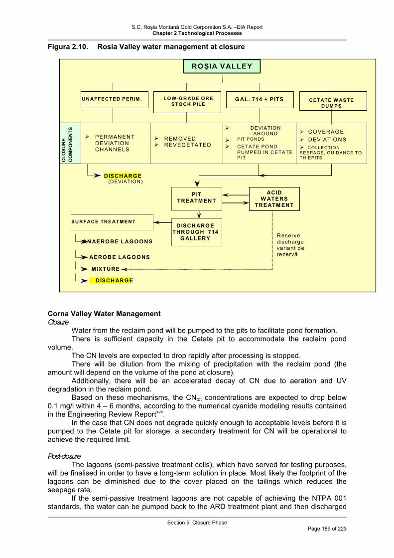
S.C. Roşia Montană Gold Corporation S.A. –EIA Report Chapter 2 Technological Processes
Section 5: Closure Phase
Page 189 of 223
Figura 2.10. Rosia Valley water management at closure
Corna Valley Water Management Closure
Water from the reclaim pond will be pumped to the pits to facilitate pond formation. There is sufficient capacity in the Cetate pit to accommodate the reclaim pond
volume. The CN levels are expected to drop rapidly after processing is stopped. There will be dilution from the mixing of precipitation with the reclaim pond (the
amount will depend on the volume of the pond at closure). Additionally, there will be an accelerated decay of CN due to aeration and UV
degradation in the reclaim pond. Based on these mechanisms, the CNtot concentrations are expected to drop below
0.1 mg/l within 4 – 6 months, according to the numerical cyanide modeling results contained in the Engineering Review Reportxvii.
In the case that CN does not degrade quickly enough to acceptable levels before it is pumped to the Cetate pit for storage, a secondary treatment for CN will be operational to achieve the required limit.
Post-closure
The lagoons (semi-passive treatment cells), which have served for testing purposes, will be finalised in order to have a long-term solution in place. Most likely the footprint of the lagoons can be diminished due to the cover placed on the tailings which reduces the seepage rate.
If the semi-passive treatment lagoons are not capable of achieving the NTPA 001 standards, the water can be pumped back to the ARD treatment plant and then discharged
DISCH ARG E (DEVIATION)
PERM ANENT DEVIATION CHANNELS
REM O VED REVEG ETATED
DEVIATION AROUND
PIT PONDS
CETATE POND PUMPED IN CETATE PIT
CO VERAG E DEVIATIO NS COLLECTION
SEEPAGE, GUIDANCE TO TH EPITS C
LOSU
RE
CO
MPO
NEN
TS
P IT TREATM ENT
DISCH ARG ETHROUG H 714
G ALLERY
SURFACE TREATM ENT
AN AEROBE LAGO O NS
AERO BE LAG O ONS
M IXTURE
DISCH ARG E
ROŞ IA VALLEY
UNAFFECTED PERIM . CETATE W ASTE DUM PS
LOW -GR ADE ORE STOCK PILE
G AL. 714 + PITS
ACID W ATERS
TREATM ENT
Reserve discharge variant de rezervă

S.C. Roşia Montană Gold Corporation S.A. –EIA Report Chapter 2 Technological Processes
Section 5: Closure Phase
Page 190 of 223
to the environment. The cyanide detoxification plant will remain operational for advanced treatment of diluted water. The existing facility allows for the required minor changes.
If necessary, an additional cyanide removal phase will be maintained to meet the 0.1 mg/l limit for CN., as per NTPA 001/2005 maximum permissible limits.
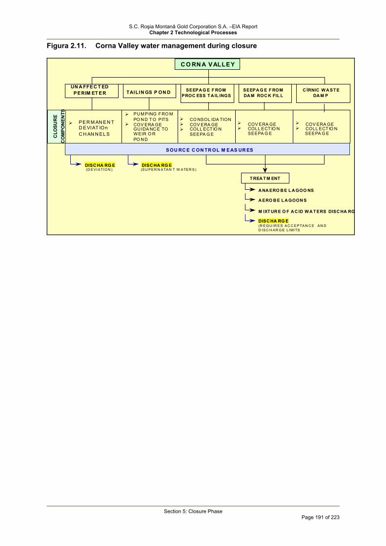
S.C. Roşia Montană Gold Corporation S.A. –EIA Report Chapter 2 Technological Processes
Section 5: Closure Phase
Page 191 of 223
Figura 2.11. Corna Valley water management during closure
T REA T M ENT
A NA ERO B E L A GOO NS
A ERO B E L A GOON S
M IXT UR E O F A C ID W A T ERS DISC HA RG
DISC HA RG E (R EQ U IR ES AC C EPTAN C E AN D D ISC H AR G E LIMITS
DISC HA RG E (D EVIATIO N )
DISC HA RG E(SU PER N ATAN T W ATER S)
PU M PING F RO M PO N D T O PITS
COV ERA GE GU IDA NC E TO W EIR O R PO N D
CO NSOL IDA TION COV ERA GE COLL ECT IO N
SEEPA G E
COV ERA GE COLL ECT IO N
SEEPA G E
COV ERA GE COLL ECT IO N
SOU RC E C ON TR OL M EAS UR ES
C O RN A VALLEY
TAILIN GS P ON D SEEPA G E F ROM PROC ESS T A IL INGS
UN A FFEC T ED PERIM ET ER
SEEPA G E F ROM DA M ROC K FIL L
C ÎRNIC W A ST E DA M P
CLO
SUR
E C
OM
PON
ENTS
PER M AN EN T D EVIAT IOn C H AN N EL S SEEPA G E

S.C. Roşia Montană Gold Corporation S.A. –EIA Report Chapter 2 Technological Processes
Section 5: Closure Phase
Page 192 of 223
Figure 2.12 Water management during closure
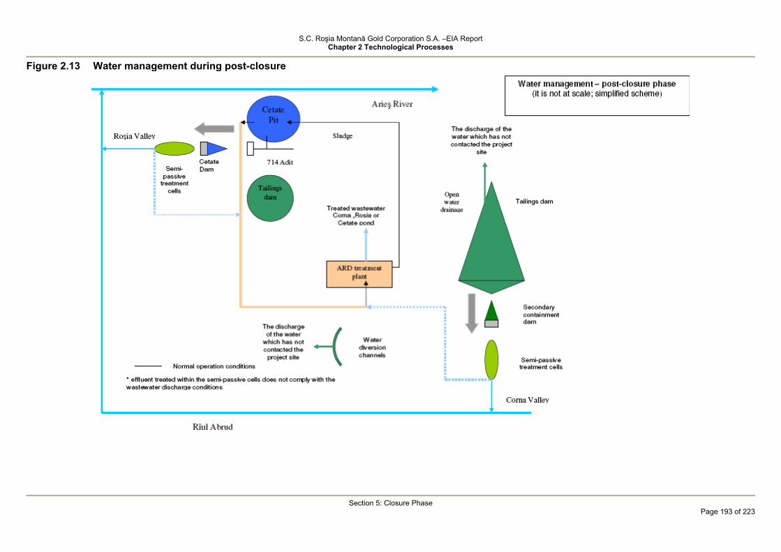
S.C. Roşia Montană Gold Corporation S.A. –EIA Report Chapter 2 Technological Processes
Section 5: Closure Phase
Page 193 of 223
Figure 2.13 Water management during post-closure

S.C. Roşia Montană Gold Corporation S.A. –EIA Report Chapter 2 Technological Processes
Section 5: Closure Phase
Page 194 of 223
5.1.5 Electricity The on-site electrical power line will be maintained during transition or close-out as
long as necessary for the operation of the wastewater treatment plant. Decommissioning will include removing the line and the towers, commensurate with the planned post-mining land use. It is possible that certain poles and cables and transformers will be turned over to the local authorities for development of local instructure. Electrical equipment, including transformers and switch-gear, will be removed where possible and resold. Although the transformers which contain polychlorinated biphenyl-bearing compounds will not be kept on site, it is assumed that they meet the criteria for storage as hazardous waste. Surplus electrical transformers that are not resold will be transported by a licensed carrier for emptying, dismantle and disposal as hazardous waste (or municipal, if tests will not ouline hazardous properties) at an approved facility.
5.1.6 Access Roads
In general, the on-site access roads will be retained during the early years of closure to continue access to work areas undergoing reclamation activities. Lockable gates and appropriate signage will restrict use of the roads. Once most of the major closure work has been completed, the culverts from the access roads will be removed and the roads will be ripped or scarified and revegetated. Certain access roads will be retained to allow for monitoring activities or, as required, for the planned post-mining land use.
5.2 Equipment and material needs, facilities, services, access roads, workforce
Dismantle/demolition works include both disassembly – hoisting – bring down operations as well as loading – transport – unloading operations. Equipment employed will be suitable for such activities.
At closure, which is anticipated to last 2 years, there will be 43 heavy mining equipment employed (loaders, haul trucks, bulldozers, cranes, excavators, etc). The workforce requirement in this period is estimated at 150 people.
At post-closure, which is anticipated to last 3 years, there will be 10 heavy mining equipment employed (loaders, haul trucks, bulldozers, cranes, excavators, etc). The workforce requirement in this period is estimated at 25 people.
Potable and Process Water Supply Systems Water requirements will diminish during closure, as the number of on-site personnel decreases and process operations cease. Drinking water requirements may then be met by retaining a contractor to deliver potable water. The fresh water supply and potable water treatment systems will be either turned over to the local authorities or decommissioned. Decommissioning activities will also include the fresh water delivery pipeline running along the Arieş river and Roşia valley, depending on the decisions to be made regarding the final land use.
On-site Sewage Treatment Facility The modular domestic wastewater treatment system, installed to cater for the construction camp, can be relocated to the processing plant site and modified. Upon completion of all closure activities requiring presence of personnel on site, this treatment plant will either be transferred to a location decided by the local authorities or decommissioned, in accordance with the planned use for the Project site. Prior to relocating or decommissioning, the wastewater treatment plant will be drained and cleaned. The components resulting from dismantling the treatment plant may be sold or recycled, in accordance with the applicable regulatory requirements. The treatment lagoons constructed in the Roşia and Corna valleys will remain after closure to ensure continuous semi-passive treatment of run-off or seepage water from the former mining sites.

S.C. Roşia Montană Gold Corporation S.A. –EIA Report Chapter 2 Technological Processes
Section 5: Closure Phase
Page 195 of 223
5.3 Pollution Sources
5.3.1 Emissions RMGC intends to decommission numerous equipment, installations, facilities and
buildings that were employed in the ore mining and processing operations with the closure and rehabilitation of the sites affected by the mining activities to follow in accordance with the Mine Rehabilitation and Closure Management Plan (ESMS Plans, Plan J).
5.3.1.1 Atmospheric emissions
The primary emissions that will affect air quality during closure include the following: The internal combustion engines of haul trucks and mobile equipment used for
decommissioning works; Dust emissions from excavation, loading, haulage, unloading of topsoil from
stockpile; Dust emissions released during the preparation of affected areas (main and
secondary containment dams, TMF surface areas, waste rock stockpiles, open pit site, processing plant site) for revegetation;
Various emissions generated when cutting up the metal structures and demolishing concrete foundations and buildings;
Various impacts from the remaining support activities (transportation of workforce, operation of thermal plant and domestic wastewater treatment plant and other activities using fuel).
Details regarding the emissions inventory at closure, with reference to the anticipated mass flow rates and other information are presented in Table 4.2.31 – 4.2.35, Section 4.2 Air.
The following measures will be taken to minimise air pollution at closure: • Sprinkling of open areas where dust-generating materials are handled. • Control of emissions on road surfaces during the dry season by use of sprinklers
and by use of inert chemical substances. • Use of portable and stationary ventilation systems and of respiratory protection
devices. • Standard operating procedures will be implemented to stop dust generating
activities during strong wind conditions. • Minimization of gas releases from fuel operations and standard operating
procedures to minimise fuel spills during handling thereof. • Minimisation of dust-generating waste/debris build up. • All operational equipment used on site will meet the strictest EU and/or
Romanian emission standards for mobile and stationary equipment. A maintenance and revision program for mobile and stationary equipment will be implemented, in order to ensure compliance with the regulatory standards.
Table 4.2.102 in Section 4.2. AIR, gives details on the emission control installations (gas treatment and discharge) as well as the air pollution prevention measures.
Monitoring activities and corrective/preventive actions are provisioned in the Air Quality Management Plan (ESMS Plans, Plan D) and Environmental and Social Monitoring Plan (ESMS Plans, Plan P).
5.3.1.2 Water Pollutant Emissions
The water pollution degree will be reduced after mining and processing operations have ended. At closure, process water and domestic wastewater will be eliminated.
The following soil pollution sources may occur at the plant site during closure: • Water from washout of equipment, tanks and pipes that were in contact with
cyanide and reagents. The detoxification circuit within the reagent management areas of the process plant will be the final component to be decommissioned, in
S.C. Roşia Montană Gold Corporation S.A. –EIA Report Chapter 2 Technological Processes
Section 5: Closure Phase
Page 196 of 223
order to maintain an onsite capability for collection and detoxification of any potential spillage that may be encountered in the decommissioning of the equipment, installations and machinery.
The DETOX plant will be the last decommissioned. Any residual cyanide that may be detected in the decommissioning of the detoxification plant itself will be neutralised using portable detoxification kits as noted in the Cyanide Management Plan and Emergency Preparedness and Spill Contingency Plan. All rinseate or cleanup compounds associated with detoxification plant decommissioning will be captured, placed in sealed containers, and transported to a licensed hazardous waste disposal facility.
• Accidental lubricant, fuel spills from equipment operating within the processing plant site. These spills will be neutralised locally in order not to be carried away by washings or runoff.
5.3.1.3 Pollutant Emissions on SOIL/SUBSOIL
The following soil pollution sources may occur at the plant site during closure: • Leaks or spillages of reagents may occur during the removal (decommissioning /
dismantling) of reagent storage structures and process facilities. These will be collected and directed to the DETOX Plant for neutralization.
• Spills within the perimeter assigned for repairing / change of oil for vehicles and equipment used at decommissioning / dismantle, transport. Leaks and/or spills within the fuel station area will be retained in mobile recipients provided with safety guards or self-closing valves. All used oil and grease and washings cotaining solvents will be collected, transferred to water-oil separators and then stored in recipients for proper waste disposal in accordance with the Waste Management Plan (Plan B);
• Gas and dust emissions from vehicles/equipment used for decommissioning/ dismantle. Mobile systems for dust and gas gathering and water spray systems will be provided.
• Dust emissions from the demolition of concrete and masonry structures and their manipulation (loading/unloading). Storage of waste/rubble generated during demolition will be monitored in order to minimise dust emissions.
• Soil cover and revegetation are also potential pollution sources during closure. • Asbestos-bearing materials will not be permitted for the construction of the
process plant or ancillary facilities, therefore no asbestos demolition waste will be generated in the closure phase of the project.
• Domestic waste will be disposed of and stored in approved off-site waste facilities. Remaining inert materials will be disposed into an own inert material landfill, covered with a soil layer, and the area revegetated. Waste from foundations and concrete bays will be demolished to ground level, the respective areas will be covered with a soil layer, reprofiled and re-vegetated. All other end-of-life facilities with exposed areas of soil will be graded, if required, and re-vegetated.
• Soils below storage tanks will be sampled and tested to confirm there is no residual contamination below each facility. Soils at the plant site (including the soil under the plant surface water run-off collection pond and under the hazardous waste temporary storage facility) will be checked for contamination. In the event that contaminants are identified, they will be remediated in situ or disposed of off-site at an approved licensed disposal facility in compliance with the Roşia Montană Project Waste Management Plan (see Plan B within the suite of plans that have been developed to support the Environmental and Social Management System).

S.C. Roşia Montană Gold Corporation S.A. –EIA Report Chapter 2 Technological Processes
Section 5: Closure Phase
Page 197 of 223
5.3.1.4 Noise and Vibration The potential sources for noise and vibrations during decommissioning/closure are: • Local and access roads (background noise); • Operation of trucks and other heavy equipment for reclamation, rehabilitation and
re-vegetation of the surface covered by the two pits, waste rock dumps, topsoil stockpiles.
• Operation of cranes and other heavy equipment used for dismantling, disassembly and demolition of processing facilities and other ancillary structures located within the project’s industrial protection zone boundary;
• Operation of loaders for haulage of waste and other materials to be recycled; • Operation of trucks and other heavy equipment used for reclamation,
rehabilitation and revegetation of the area covered by the tailings pond, low-grade ore stockpile, processing plant footprint, access roads etc.;
• Transport of personnel to the decommissioning/closure areas.
Noise and Vibration Mitigation Measures The noise and vibration mitigation measures will be BAT as specified in Table 4.3.5,
Section 4.3 Noise and Vibrations. The measures proposed to reduce the noise and vibration impacts associated with
the Project consist of a combination of the following measures: • Engineering measures: sound insulation for the buildings at the process plant site
etc.; • Institutional control implementation by establishment of protection zones,
installation and imposing of speed limits for vehicles, suitable safety equipment for employees as per the health and safety program defined by the RMGC Occupational Health and Safety Plan.
• Implementation of adequate control techniques and procedures such as maintenance and repairing schedule for the major equipment and machinery to ensure that sound emissions comply with the normal operational limits;
• Management Controls, active engagement of the public and other external factors in the identification and resolution of noise and vibration issues through the communication mechanisms defined in the Public Consultation and Disclosure Plan (ESMS Plans, Plan K) and the procedures for corrective and preventive actions described in the Roşia Montană Project Environmental and Social Management Plan (ESMS Plans, Plan A).
• Long-term monitoring of the noise and vibration impact on the workforce, sensitive structures, potentially sensitive fauna species and human receptors in the vicinity of the project’s industrial protection zone boundary.
5.3.2 Waste
The following categories of waste will be generated during the closure of mining and ore processing activities and connected activities within the Roşia Montană Project:
• municipal or similar waste • non-hazardous (biodegradable, packaging waste); • slurry from the wastewater treatment plant; • non-inert demolition waste; • production waste • hazardous production waste; • non-hazardous production waste;
S.C. Roşia Montană Gold Corporation S.A. –EIA Report Chapter 2 Technological Processes
Section 5: Closure Phase
Page 198 of 223
• waste generated by medical activities. • Details on the onsite waste management are presented in Section 3.0 WASTE.
5.4 Revegetation
Rehabilitation and reconstruction of land areas affected by mining operations will be conducted in accordance with the current approved version of the Mine Rehabilitation and Closure Management Plan (Plan H within the suite of plans that have been developed to support the Environmental and Social Management System) and with selected elements of the Biodiversity Conservation Plan. The works will consist of two major categories as follows:
Mechanical stabilisation of the surface, including grading and scarification (for development of suitable drainage conduits) and backfiling of the main low areas or holes by using suitable aggregates placed normally as layers compacted separately.
Revegetation of stabilised surfaces, including: • Covering of reclamation areas previously prepared (i.e. graded, scarified and
compacted) with a topsoil layer from the topsoil stockpiles or other borrow areas. • Soil fertilisation, as required. • Seeding of native species of perennial herbs. • Planting and organic fertilisation of native species of deciduous trees. • Irrigation in phases of the revegetated areas. • The overall objective of these activities is to support the potential erosion
management efforts and harmonize the rehabilitated areas with the surrounding deciduous forests and to sustain the development of local and regional biodiversity.
• Revegetation procedures will take into consideration the following minimal elements: • In order to avoid destruction of soil structure and drainage capacity, planting activities
will not be conducted under adverse meteorological conditions or with soils oversaturated with water.
• The weeds will be removed mechanically and destroyed prior to replanting of site areas.
• Extreme heavy equipment and repeated trips over the same replanting areas will be avoided.
• No heavy equipment will be used in the replanted areas. All planted areas affected by such inadequate equipment will be rehabilitated.
• Topsoil placement from borrow areas or soil stockpiles over the previously prepared soil layers and around areas of arboreal sapling will be carried out through maximum 150mm thick layers. Each layer will be slightly compacted prior to the placement of a new topsoil layer.
• During reclamation and topsoil placement, the large rock fragments and waste will be removed.
• The properly dried topsoil will be graded and profiled to ensure proper drainage. All holes or other unevenness will be removed.
• The manufacturer's guidelines with respect to the storage, manipulation and application of fertilizers or herbicides will be followed. Empty chemical substance containers will be stored as municipal or hazardous waste, in accordance with the Waste Management Plan. The deciduous tree species will be tested and approved by the competent authorities
within the Ministry of Agriculture, Forests and Rural Development prior to planting.

S.C. Roşia Montană Gold Corporation S.A. –EIA Report Chapter 2 Technological Processes
Section 5: Closure Phase
Page 199 of 223
Planting will be scheduled to take place under favourable conditions, with warm and wet weather and a wet and workable soil. No planting will be carried out in periods of persistent cold and dry wind or in case of frozen, water-saturated or excessively dry soils.
Tree planting will be conducted in early spring or late autumn, as soon as possible after the onsite delivery of the planting material. In case the planting is to be deferred, the plants should be protected against degradation or unfavourable weather.
The holes for planting of sapling excavated on sloping surfaces will have vertical sides and horizontal base; the hole diameter will be sufficient to contain the fully stretched roots.
Newly planted trees will be protected by guard fences and/or supporting pegs.

S.C. Roşia Montană Gold Corporation S.A. –EIA Report Chapter 2 Technological Processes
Section 6: Use of BAT
Page 200 of 223
6 Use of the best available techniques (BAT) 6.1 Limit values for the relevant parameters achieved by application of the
proposed techniques and the best available techniques
Table 2-44 lists the main environmental parameters of the Project (i.e. consumption of power, water consumption, air pollutant emissions, pollutant releases to water and generation of identified categories of waste) relative to the techniques or approaches to be used for the management of these parameters and/or mitigation of their potential impact.
.
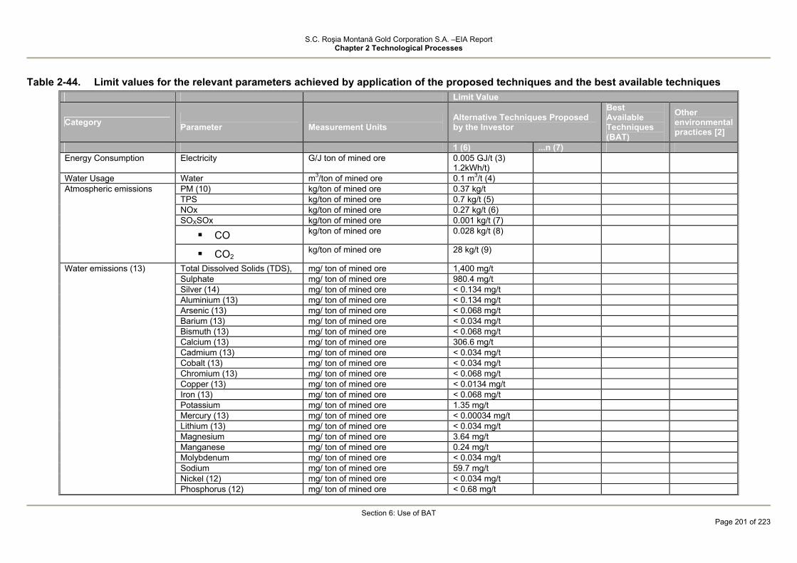
S.C. Roşia Montană Gold Corporation S.A. –EIA Report Chapter 2 Technological Processes
Section 6: Use of BAT
Page 201 of 223
Table 2-44. Limit values for the relevant parameters achieved by application of the proposed techniques and the best available techniques
Limit Value
Category Parameter
Measurement Units
Alternative Techniques Proposed by the Investor
Best Available Techniques (BAT)
Other environmental practices [2]
1 (6) ...n (7) Energy Consumption Electricity G/J ton of mined ore 0.005 GJ/t (3)
1.2kWh/t)
Water Usage Water m3/ton of mined ore 0.1 m3/t (4) PM (10) kg/ton of mined ore 0.37 kg/t TPS kg/ton of mined ore 0.7 kg/t (5) NOx kg/ton of mined ore 0.27 kg/t (6) SOXSOx kg/ton of mined ore 0.001 kg/t (7)
CO kg/ton of mined ore 0.028 kg/t (8)
Atmospheric emissions
CO2 kg/ton of mined ore 28 kg/t (9)
Total Dissolved Solids (TDS), mg/ ton of mined ore 1,400 mg/t Sulphate mg/ ton of mined ore 980.4 mg/t Silver (14) mg/ ton of mined ore < 0.134 mg/t Aluminium (13) mg/ ton of mined ore < 0.134 mg/t Arsenic (13) mg/ ton of mined ore < 0.068 mg/t Barium (13) mg/ ton of mined ore < 0.034 mg/t Bismuth (13) mg/ ton of mined ore < 0.068 mg/t Calcium (13) mg/ ton of mined ore 306.6 mg/t Cadmium (13) mg/ ton of mined ore < 0.034 mg/t Cobalt (13) mg/ ton of mined ore < 0.034 mg/t Chromium (13) mg/ ton of mined ore < 0.068 mg/t Copper (13) mg/ ton of mined ore < 0.0134 mg/t Iron (13) mg/ ton of mined ore < 0.068 mg/t Potassium mg/ ton of mined ore 1.35 mg/t Mercury (13) mg/ ton of mined ore < 0.00034 mg/t Lithium (13) mg/ ton of mined ore < 0.034 mg/t Magnesium mg/ ton of mined ore 3.64 mg/t Manganese mg/ ton of mined ore 0.24 mg/t Molybdenum mg/ ton of mined ore < 0.034 mg/t Sodium mg/ ton of mined ore 59.7 mg/t Nickel (12) mg/ ton of mined ore < 0.034 mg/t
Water emissions (13)
Phosphorus (12) mg/ ton of mined ore < 0.68 mg/t

S.C. Roşia Montană Gold Corporation S.A. –EIA Report Chapter 2 Technological Processes
Section 6: Use of BAT
Page 202 of 223
Limit Value
Category Parameter
Measurement Units
Alternative Techniques Proposed by the Investor
Best Available Techniques (BAT)
Other environmental practices [2]
1 (6) ...n (7) Lead (12) mg/ ton of mined ore < 0.034 mg/t Silicon (12) mg/ ton of mined ore < 0.68 mg/t Strontium mg/ ton of mined ore 1.57 mg/t Titanium (12) mg/ ton of mined ore < 0.068 mg/t Vanadium (12) mg/ ton of mined ore < 0.0134 mg/t Yttrium (12) mg/ ton of mined ore < 0.0068 mg/t Zinc (12) mg/ ton of mined ore < 0.0134 mg/t Zirconium (12) mg/ ton of mined ore < 0.034 mg/t Total suspended particles mg/ ton of mined ore 24 mg/t CBO5 mg/ ton of mined ore To be determined CCO-Cr mg/ ton of mined ore To be determined Nitrates mg/ ton of mined ore < 24 mg/t Nitrites mg/ ton of mined ore < 0.05 mg/t Total Phosphorus mg/ ton of mined ore 0.05 mg/t Substances extractable in organic solvents
mg/ ton of mined ore < 2.4 mg/t
Waste rock kg/ton of mined ore 1,270 kg/t Overburden kg/ton of mined ore 22 kg/t (13) Topsoil kg/ton of mined ore 3.5 kg/t Sludge from Domestic Wastewater Treatment Plant
kg/ton of mined ore 0.00025 kg/t
Demolition mixed waste kg/ton of mined ore 0.01 kg/t Scrap metal kg/ton of mined ore 0.05 kg/t Asbestos Waste kg/ton of mined ore 0.0004 kg/t Paint residue kg/ton of mined ore 0.0000005 kg/t Contaminated soil kg/ton of mined ore 0.000009 kg/t (14) Empty containers kg/ton of mined ore 0.00004 kg/t (15) Used hydraulic oil kg/ton of mined ore 0.007 kg/t (16) Used lubricating oil kg/ton of mined ore 0.016 kg/t (17) Used grease kg/ton of mined ore 0.0004 kg/t (18) Used Oil Filters kg/ton of mined ore 0.004 kg/t (19) Solvent residue kg/ton of mined ore 0.00001 kg/t (20) Used Tyres kg/ton of mined ore 0.0005 kg/t (21) Lead acid batteries kg/ton of mined ore 0.000035 kg/t (22)
General waste
End-of-Life Vehicles kg/ton of mined ore 0.00002 kg/t (23)

S.C. Roşia Montană Gold Corporation S.A. –EIA Report Chapter 2 Technological Processes
Section 6: Use of BAT
Page 203 of 223
Limit Value
Category Parameter
Measurement Units
Alternative Techniques Proposed by the Investor
Best Available Techniques (BAT)
Other environmental practices [2]
1 (6) ...n (7) (1) European Commission, 2004; Reference Document on Best Available Techniques for Management of Tailings and Waste-Rock in Mining Activities (2) In accordance with the Helsinki Convention on the transboundary effects of industrial accidents (1992). (3) Based on an estimated consumption of 730 MWhr/year during construction, 402,200 MWhr/year during operations and 770 MWhr/year during closure. (4) Assumes average fresh water supply for mining of approximately 210 m3/hr at a throughput of approximately 13 Mt/annum of processed ore. Fresh water will be required to accommodate process water requirement of approximately 14%; it should be noted that approximately 86% of the process water requirement will come from recyclable sources (e.g. TMF supernatant water, effluent from wastewater and municipal wastewater treatment plants). (5) Assumes emissions of total suspended particulates (TPS) of 154,044 tons at a total amount of processed ore of 214,905 Mt. (6) Assumes emissions of NOx of 58,105 tons at a total amount of processed ore of 214,905 Mt. (7) Assumes emissions of SOx of 175 tons at a total amount of processed ore of 214,905 Mt. (8) Assumes emissions of CO of 6,197 tons at a total amount of processed ore of 214,905 Mt. (9) Assumes a ratio between CO2 and CO of about 1000. (10) These concentrations assume that the amount of effluent released to the wastewater treatment plant is 400 m3/hr over a period of 24 hours. Under normal operation conditions, most of these releases will be routed to the processing plant as make-up water with maintenance of base flows in Roşia and Corna valleys. Under extreme dry conditions, most of these effluents will be routed to the Roşia valley in order to maintain base flow. During closure, the wastewater treatment plant will be used to collect and treat wastewater with an estimated annual discharge volume under 400 m3/hr. (11) The test results indicated concentrations below detection limits; for this reason, the concentrations of the respective parameters under most unfavourable conditions were estimated as being equal to the detection limit; see Section 4.1 and Table (12) Categories and sub-categories described in the National Waste Management Plan approved by the Government of Romania (2004) and in the draft Directive of the European Parliament and Council for Management of Waste from Extractive Industries [2003/0107(COD)], Brussels, February 2003. See Section 3 and Table 3.3 (a), (b) and (c). (13) Based on a typical estimated density of the overburden deposit of 1,700 kg/m3. (14) This represents the potential amount of contaminated soil as a result of oils change or accidental fuel spills. Actual quantities generated will depend on the actual spill clean-up scenario or demolition associated with historically contaminated soil. (15) Assumes no hazardous material residues are present. (16) Assumes oils will have a density of 880 kg/m3 (17) Assumes oils will have a density of 880 kg/m3 (18) Assumes grease will have a density of 950 kg/m3 (19) Assumes grease will have a density of 950 kg/m3 (20) The amount of generated waste assumes a quantity of 2 kg of solvent waste for each fleet vehicle or mining equipment. (21) Assumes a full change of tyres for each vehicle or mining equipment every 2 years. Accordingly, it is assumed that on average the fleet vehicle tyres weigh 15 kg and the mining equipment tyres weigh 4000 kg. For the construction phase, the generated tyre waste corresponds to a number of 240 vehicle tyres per year and 44 mining equipment tyres per year. For the operational phase, the generated tyre waste corresponds to a number of 58 vehicle tyres per year and 96 mining equipment tyres per year. For the “active” closure phase (the first two years of closure) the generated tyre waste corresponds to a number of 40 vehicle tyres per year and 96 mining equipment tyres per year; for the last three years of closure the generated tyre waste corresponds to a number of 40 vehicle tyres per year and 33 mining equipment tyres per year.
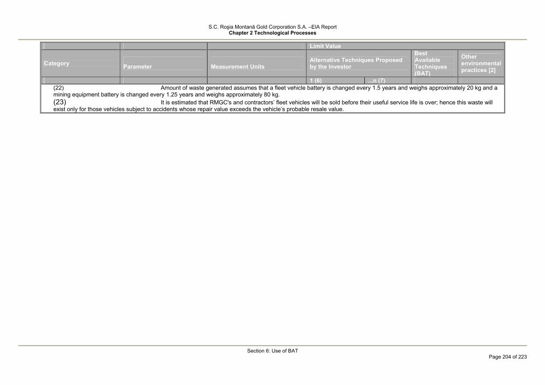
S.C. Roşia Montană Gold Corporation S.A. –EIA Report Chapter 2 Technological Processes
Section 6: Use of BAT
Page 204 of 223
Limit Value
Category Parameter
Measurement Units
Alternative Techniques Proposed by the Investor
Best Available Techniques (BAT)
Other environmental practices [2]
1 (6) ...n (7) (22) Amount of waste generated assumes that a fleet vehicle battery is changed every 1.5 years and weighs approximately 20 kg and a mining equipment battery is changed every 1.25 years and weighs approximately 80 kg. (23) It is estimated that RMGC's and contractors’ fleet vehicles will be sold before their useful service life is over; hence this waste will exist only for those vehicles subject to accidents whose repair value exceeds the vehicle’s probable resale value.

S.C. Roşia Montană Gold Corporation S.A. –EIA Report Chapter 2 Technological Processes
Section 6: Use of BAT
Page 205 of 223
As shown in Table 2-44 the specific "limit values" with just a few exceptions are not provided by either the European Union guidelines regarding the best available techniques or the best environmental practices. However, the fundamental management practices to be applied by RMGC for the Roşia Montană Project for the management of these impacts are consistent with the recommendations regarding the best available techniques and best environmental practices. As an example it can be stated that the assessment of the environmental and social management system for the Roşia Montană Project based on the international standard ISO 140011 is consistent with the provisions of the Helsinki Convention, 1992, as it has been documented by the Convention on transboundary effects of industrial accidents (UNECE, 2003)2, Annex VI "Preventive measures pursuant to Article 6". These specific "preventive measures" closely correspond to the provisions of the ISO 14001 Standard, and include following:
• The setting of general or specific safety objectives; • The identification of those hazardous activities which require special preventive
measures; • The evaluation of risk analyses or of safety studies for hazardous activities and
an action plan for the implementation of necessary risk management/mitigation measures;
• The provision to the competent authorities of the information needed to assess risks;
• The application of the most appropriate technology in order to prevent industrial accidents and protect human beings and the environment;
• The undertaking of the appropriate education and training of all persons engaged in hazardous activities;
• The establishment of internal managerial structures and practices designed to implement and maintain safety regulations effectively;
1 ISO 14001:2004, Environmental Management Systems / Requirements with Guidance for Use; International Organisation for Standardisation, Geneva, Switzerland, 2004.
2See http://www.unece.org/env/teia/text.htm. Convention Signatory Countries include: Albania, Austria, Belgium, Bulgaria, Canada, Denmark, Estonia, Finland, France, Germany, Greece, Hungary, Italy, Latvia, Lithuania, Luxemburg, Holland, Norway, Portugal, Russian Federation, Spain, Sweden, Switzerland, United Kingdom and Northern Ireland and the United States of America.

S.C. Roşia Montană Gold Corporation S.A. –EIA Report Chapter 2 Technological Processes
Section 6: Use of BAT
Page 206 of 223
• The monitoring and auditing of hazardous activities and the carrying out of inspections.
Other considerations contained in the Convention which are consistent with the
implementation of a management system based on the ISO 14001 Standard, include Annex V "Analysis and Evaluation" and Annex VII "Emergency Preparedness Measures Pursuant to Article 8". There are similar correlations between some of the best available techniques presented in the EU Reference Document on Best Available Techniques for Tailings and Waste Rock Management in the Mining Activities and the strategies adopted by the Roşia Montană Project. Table 2-45 summarises the strategies to be adopted by RMGC for the management of the various parameters contained in Table 2-44, while at the same time providing examples of the best available techniques reproduced in these strategies.
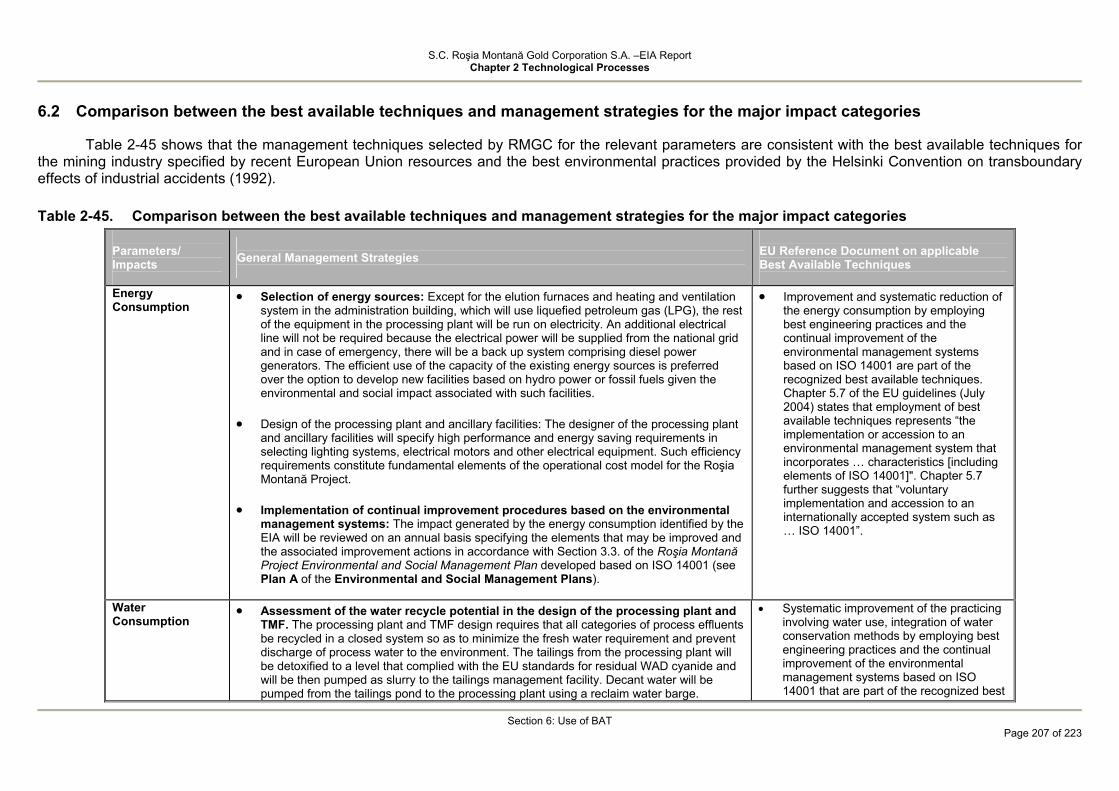
S.C. Roşia Montană Gold Corporation S.A. –EIA Report Chapter 2 Technological Processes
Section 6: Use of BAT
Page 207 of 223
6.2 Comparison between the best available techniques and management strategies for the major impact categories
Table 2-45 shows that the management techniques selected by RMGC for the relevant parameters are consistent with the best available techniques for the mining industry specified by recent European Union resources and the best environmental practices provided by the Helsinki Convention on transboundary effects of industrial accidents (1992). Table 2-45. Comparison between the best available techniques and management strategies for the major impact categories
Parameters/ Impacts
General Management Strategies
EU Reference Document on applicable Best Available Techniques
Energy Consumption
• Selection of energy sources: Except for the elution furnaces and heating and ventilation system in the administration building, which will use liquefied petroleum gas (LPG), the rest of the equipment in the processing plant will be run on electricity. An additional electrical line will not be required because the electrical power will be supplied from the national grid and in case of emergency, there will be a back up system comprising diesel power generators. The efficient use of the capacity of the existing energy sources is preferred over the option to develop new facilities based on hydro power or fossil fuels given the environmental and social impact associated with such facilities.
• Design of the processing plant and ancillary facilities: The designer of the processing plant
and ancillary facilities will specify high performance and energy saving requirements in selecting lighting systems, electrical motors and other electrical equipment. Such efficiency requirements constitute fundamental elements of the operational cost model for the Roşia Montană Project.
• Implementation of continual improvement procedures based on the environmental
management systems: The impact generated by the energy consumption identified by the EIA will be reviewed on an annual basis specifying the elements that may be improved and the associated improvement actions in accordance with Section 3.3. of the Roşia Montană Project Environmental and Social Management Plan developed based on ISO 14001 (see Plan A of the Environmental and Social Management Plans).
• Improvement and systematic reduction of the energy consumption by employing best engineering practices and the continual improvement of the environmental management systems based on ISO 14001 are part of the recognized best available techniques. Chapter 5.7 of the EU guidelines (July 2004) states that employment of best available techniques represents “the implementation or accession to an environmental management system that incorporates … characteristics [including elements of ISO 14001]". Chapter 5.7 further suggests that “voluntary implementation and accession to an internationally accepted system such as … ISO 14001”.
Water Consumption
• Assessment of the water recycle potential in the design of the processing plant and TMF. The processing plant and TMF design requires that all categories of process effluents be recycled in a closed system so as to minimize the fresh water requirement and prevent discharge of process water to the environment. The tailings from the processing plant will be detoxified to a level that complied with the EU standards for residual WAD cyanide and will be then pumped as slurry to the tailings management facility. Decant water will be pumped from the tailings pond to the processing plant using a reclaim water barge.
• Systematic improvement of the practicing involving water use, integration of water conservation methods by employing best engineering practices and the continual improvement of the environmental management systems based on ISO 14001 that are part of the recognized best

S.C. Roşia Montană Gold Corporation S.A. –EIA Report Chapter 2 Technological Processes
Section 6: Use of BAT
Page 208 of 223
Parameters/ Impacts
General Management Strategies
EU Reference Document on applicable Best Available Techniques
• Assessment of the water conservation methods in the design of the drinking water
supply and domestic wastewater treatment systems: The designer employed by RMGC will specify the installation of water reclaim systems in showers, toilets, dishwashers and other equipment or appliances specific to canteens. In addition, drinking water distribution or wastewater collection systems will be provided in administration buildings, canteens, processing plant buildings or construction camp during the construction phase.
• Implementation of continual improvement procedures based on the environmental
management systems: The impacts generated by the water consumption identified by the EIA will be reviewed on an annual basis specifying the elements that may be improved and the associated improvement actions in accordance with Section 3.3. of the Roşia Montană Project Environmental and Social Management Plan developed based on ISO 14001.
• Water discharge to environment: There will be no release of process and/or acid water to the environment. Waters will be discharged to the Corna and Rosia valleys (to maintain environmental base flows) only after suitable treatment to meet the quality standards.
available techniques; see UE Reference Document, July 2004).
The decant water in the tailings pond will be recycled. In some cases, it is possible that this water be released to natural streams but only after treatment. Chapter 4.3.9. (EU Reference Document, March 2004)
Atmospheric emissions
• Employment of dust control systems in the ore processing activities: The processing plant designer will specify that dust control systems be installed in the critical areas of the crushing and milling circuits in order to reduce the amount of airborne dust at the workplace. The effectiveness of these systems will be monitored regularly in accordance with the Air Quality Management Plan (see Plan D of the Roşia Montană Project Environmental and Social Management System). The Air Quality Management Plan will be updated periodically by implementing continual improvement characteristics that are provided in the Roşia Montană Project Environmental and Social Management System.
• Seasonal dust control along the ore haul roads, unsealed roads and tailing beaches.
During dry periods, regular watering of roads (and depending on the requirement, of the tailing beaches) will be planned in order to maintain particulate level within the limit vales provided by the relevant national regulations. The effectiveness of these systems will be monitored regularly in accordance with the Air Quality Management Plan, which will be updated periodically by implementing continual improvement characteristics that are provided in the Roşia Montană Project Environmental and Social Management System.
• Systematic improvement of the dust management and control practices, improvement of fuel efficiency and reduction of atmospheric emissions associated to organic matter combustion or decomposition by employing best engineering practices and the continual improvement of the environmental management systems based on ISO 14001 are part of the best available techniques.
2 • Progressive rehabilitation of the mine sites
or areas affected by mining is part of the best available practices, as shown in Chapter 4.3.6 (EU Reference Document,

S.C. Roşia Montană Gold Corporation S.A. –EIA Report Chapter 2 Technological Processes
Section 6: Use of BAT
Page 209 of 223
Parameters/ Impacts
General Management Strategies
EU Reference Document on applicable Best Available Techniques
Atmospheric emissions (continued)
• Progressive environmental rehabilitation and restoration within the mine sites or
areas affected by mining: Such areas will be progressively rehabilitated and revegetated to eliminate dust sources, as from mid mine life-cycle in accordance with the Mine Closure and Reclamation Plan (see Plan J of the Environmental and Social Management System). The Plan will be updated periodically by implementing management reviews and continual improvement characteristics that are provided in the Roşia Montană Project Environmental and Social Management System.
• Implementation of continual improvement procedures based on the environmental
management systems: The impacts generated by the atmospheric emissions identified by the EIA will be reviewed on an annual basis specifying the elements that may be improved and the associated improvement actions in accordance with Section 3.3. of the Roşia Montană Project Environmental and Social Management Plan developed based on ISO 14001.
• Incorporation of fuel consumption efficiency requirement in the specifications for
heavy machinery, vehicles, stationary diesel generators and boilers running on liquid fuel or natural gas: The fuel efficiency was identified as a critical element in selecting machinery, vehicles, stationary diesel generators as well as elution furnaces and heating and ventilation systems operating on LPG. Such efficiency requirements constitute fundamental elements of the operational cost model for the Roşia Montană Project.
• Incorporation of fuel consumption efficiency requirement in the specifications for
heavy machinery, vehicles, stationary diesel generators and boilers running on liquid fuel or natural gas: The fuel efficiency was also identified as a critical element in developing maintenance programs for machinery, vehicles, stationary diesel generators as well as elution furnaces and heating and ventilation systems operating on LPG.
• Removal of wood hydro-decomposition processes as potential CO2 source in the
design of the TMF and Cetate catchment dam: The requirements regarding the construction of the TMF and Cetate water catchment dam include disposal and capitalization of timber and removal of vegetation in order to reduce the amount of organic matter in the water pond. Removal of timber and other types of vegetal material will minimise the generation potential of CO2 resulting from decomposition of organic matter as a result of pond flooding in conjunction with the reduction of the potential impact, due to presence of organic matter, to the water treatment processes and ore processing chemistry.
July 2004). Chapter 5.2 also states that the rehabilitation of the areas taken up by waste rock dumps and development of environmental rehabilitation norms “…during the planning phase of an activity, including cost estimation and their timely update" is also part of the best available practices.
2 2 2 2
See above 2 2 2 2 2 2 2 2

S.C. Roşia Montană Gold Corporation S.A. –EIA Report Chapter 2 Technological Processes
Section 6: Use of BAT
Page 210 of 223
Parameters/ Impacts
General Management Strategies
EU Reference Document on applicable Best Available Techniques
Emissions of process pollutants to waters Emissions of process pollutants to waters (continued)
• Process water management system without discharge to environment: Under normal operating conditions, there will be no releases of process water to the environment. Process water and detoxified tailings will be retained in the tailings management pond. A closed system is employed for recycling cyanide water by thickening tailings prior to detoxification and returning decant water to the milling circuit. Water in the tailings slurry, after detoxification, will ultimately get into the TMF, from where it will be reclaimed. The seepage from the tailings pond will be collected via a sump located upstream of a secondary containment dam provided with impervious core from where it will be pumped back to the tailings pond. The water in the tailings pond will be pumped back to the processing plant to be used in the ore processing, maintaining the TMF freeboard and minimizing the fresh water requirement.
• Implementation of continual improvement procedures based on the environmental
management systems: The impacts generated by the water consumption identified by the EIA will be reviewed on an annual basis specifying the elements that may be improved and the associated improvement actions in accordance with Section 3.3. of the Roşia Montană Project Environmental and Social Management Plan developed based on ISO 14001.
See above
• Reuse of process water in order to reduce overall emissions is recognized as being part of the best available techniques according to chapters 5.2 and 4.3.11 (EU Reference Document, July 2004)
• Collection of seepage through the dam
body and use of repumping systems is also part of the best available techniques according to chapters 5.2 (EU Reference Document, July 2004) Chapter 4.4.12 highlights the fact that the "seepage through dams body .... must not be seen as a negative element. It is important that this seepage be controlled .... in order to ensure stability by reducing pore pressure ... it is essential that such seepage be rigorously controlled and managed". Chapter 4.3.10 shows that “… it could be more suitable to install recycling systems… [that will] collect rather than prevent the flow of seepage thus allowing that water be collected for treatment.
• Systematic identification of the options to
minimise or remove water requirement by employing best engineering practices and the continual improvement of the environmental management systems are also part of the best available techniques; see chapter 5.7
• Seepage through the dam is collected in channels and its quality is monitored. Should it be adequate in terms of quality, water will be discharged onto soil. If not adequate, water will be treated. Another option is to collect and pump this water back to the tailings pond. Chapter 4.3.10. (EU Reference Document, March 2004)

S.C. Roşia Montană Gold Corporation S.A. –EIA Report Chapter 2 Technological Processes
Section 6: Use of BAT
Page 211 of 223
Parameters/ Impacts
General Management Strategies
EU Reference Document on applicable Best Available Techniques
• TMF runoff. Runoff water is collected and pumped back to the tailings pond via the
secondary containment dam. Passive treatment cells are provided downstream of the secondary containment dam. This water will be released to the environment only if it is of suitable quality. If not, it will be pumped to the wastewater treatment facility.
• ARD treatment All ARD within the Project site will be drained, collected and treated
through the ARD treatment facility using milk of lime and air oxidation. Semi-passive treatment cells will be constructed downstream of the TMF dams for the seepage through the dams
• Active treatment by neutralization with
alkaline reagents. Hydrated lime is the reagent typically used to treat acid water. Passive treatment using chemical and biological reactions Chapter 4.3.11.5 (EU Reference Document, March 2004)
Emissions of pollutants to waters consisting of effluents from the ARD and domestic wastewater treatment plants Emissions of pollutants to waters consisting of effluents from the ARD and domestic wastewater treatment plants (continued)
• The design of the wastewater treatment plant in order to reduce the contaminant concentrations to the levels accepted by the relevant Romanian standards: The wastewater treatment plant is designed to minimise the contaminant load in the treated effluent and have this effluent in compliance with the water quality standards accepted by the Romanian regulations as a result of negotiations and discussions. Additional details regarding the technical capability of the wastewater treatment system are given in Section 4.1.
• The design and operational phase of the domestic wastewater treatment plant in
order to reduce the contaminant concentrations below the levels accepted by the relevant national standards: The domestic wastewater treatment plant used during the construction phase and the treatment plant that will be installed within the processing plant site during the operational phase will be designed to minimise the contaminant loaf of the resulting effluents in compliance with the levels accepted by the Romanian regulations in force.
• Implementation of continual improvement procedures based on the environmental
management systems: The impacts generated by the effluents resulting from the wastewater and wastewater treatment plant and domestic wastewater treatment plant, respectively identified by the EIA will be reviewed on an annual basis specifying the elements that may be improved and the associated improvement actions (i.e. training/conservation actions where energy use is concerned) in accordance with Section
• As per Chapter 5.2 (EU Reference Document, July 2004) where the removal of the ARD potential is not possible, “the control of the impact generated by ARD … or application of options regarding treatment of this acid water” is considered best available practice. Treatment of acid water by active methods (i.e. ARD treatment plant) is recognized, despite the high costs involved, as part of the best available techniques; see Chapters 4.3.11.5 (EU Reference Document, July 2004).
• Systematic reduction of contaminant loads
in the effluents resulting from industrial and domestic wastewater treatment by employing adequate engineering procedures in compliance with ISO 14001 as well as the continual improvement of the environmental management systems

S.C. Roşia Montană Gold Corporation S.A. –EIA Report Chapter 2 Technological Processes
Section 6: Use of BAT
Page 212 of 223
Parameters/ Impacts
General Management Strategies
EU Reference Document on applicable Best Available Techniques
3.3. of the Roşia Montană Project Environmental and Social Management Plan developed based on ISO 14001.
based on ISO 14001 are also part of the best available techniques; see chapter 5.7 (EU Reference Document, July 2004).
Acid rock drainage management
• Prevention of ARD occurrence. Separate the waste rocks in rocks with ARD potential, rocks with low ARD potential and/or neutral rocks by systematic testing of the samples in the boreholes previously developed in the operational sites and separate storage of the rocks.
• ARD treatment All ARD within the Project site resulting from historical operation and/or
Project development will be drained, collected and treated through the ARD treatment facility using milk of lime and air oxidation. Semi-passive treatment cells will be constructed downstream of the TMF dams for the seepage through the dams.
• Geological zonation of the sulphidic tailing depositions. On open pit mining, it is often possible to extract rocks selectively and separate them subject to their ARD potential. Chapter 4.3.11.5 (EU Reference Document, March 2004)
• Active ARD treatment by neutralization with alkaline reagents. „Hydrated lime is the reagent typically used to treat acid water”.
• Passive treatment using chemical and biological reactions Chapter 4.3.11.5 (EU Reference Document, March 2004)
Municipal, production and medical waste (all subcategories)
Municipal, production
• Implementation of continual improvement procedures based on the environmental management systems: The impacts generated by the water consumption identified by the EIA will be reviewed on an annual basis specifying the elements that may be improved and the associated improvement actions in accordance with Section 3.3. of the Roşia Montană Project Environmental and Social Management Plan developed based on ISO 14001. It must be noted that although certain waste categories can be subject to strategies for reducing the amounts of generated waste, the amount of tailings is directly dependant on the amount of processed ore. The reduction of waste rock amount is limited to what can be achieve by employing efficient and cost-effective mining methods.
• Removal of some of the waste rock volume by placing a part of the waste back in the Cîrnic Pit and revegetation of the waste rock dumps. Removal of a part of the overburden and waste rock by backfiling of the Cîrnic pit will reduce the stockpiled waste rock by 26%. All waste rock dumps will be reprofiled, covered with topsoil and revegetated as specified in the Mine Rehabilitation and Closure Management Plan (ESMS Plans, Plan J)
2
• Systematic reduction of waste volumes and, if possible, removal of waste streams by application of specific principles for continous improvement of environmental management systems based on ISO 14001 are also part of the best avilable techniques; see Section 5.7 (EU Reference Document, July 2004)
• As per Section 5.2 (EU Reference
Document, July 2004) reduction of the operational surface by using a volume of waste rock as high as possible for backfilling purposes is part of the best available techniques. Rehabilitation of areas covered by the waste rock dumps and preparation of rehabilitation regulations "... during
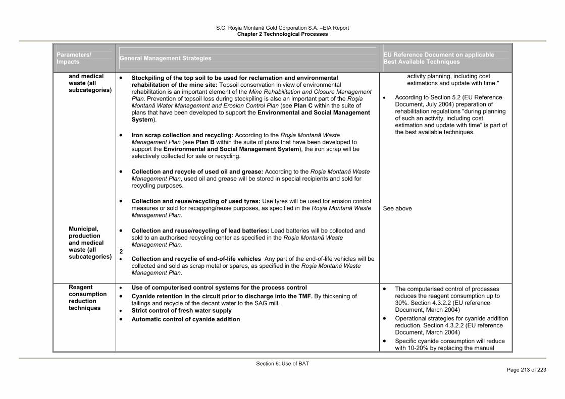
S.C. Roşia Montană Gold Corporation S.A. –EIA Report Chapter 2 Technological Processes
Section 6: Use of BAT
Page 213 of 223
Parameters/ Impacts
General Management Strategies
EU Reference Document on applicable Best Available Techniques
and medical waste (all subcategories)
Municipal, production and medical waste (all subcategories)
• Stockpiling of the top soil to be used for reclamation and environmental rehabilitation of the mine site: Topsoil conservation in view of environmental rehabilitation is an important element of the Mine Rehabilitation and Closure Management Plan. Prevention of topsoil loss during stockpiling is also an important part of the Roşia Montană Water Management and Erosion Control Plan (see Plan C within the suite of plans that have been developed to support the Environmental and Social Management System).
• Iron scrap collection and recycling: According to the Roşia Montană Waste Management Plan (see Plan B within the suite of plans that have been developed to support the Environmental and Social Management System), the iron scrap will be selectively collected for sale or recycling.
• Collection and recycle of used oil and grease: According to the Roşia Montană Waste
Management Plan, used oil and grease will be stored in special recipients and sold for recycling purposes.
• Collection and reuse/recycling of used tyres: Use tyres will be used for erosion control
measures or sold for recapping/reuse purposes, as specified in the Roşia Montană Waste Management Plan.
• Collection and reuse/recycling of lead batteries: Lead batteries will be collected and
sold to an authorised recycling center as specified in the Roşia Montană Waste Management Plan.
2 • Collection and recyclie of end-of-life vehicles Any part of the end-of-life vehicles will be
collected and sold as scrap metal or spares, as specified in the Roşia Montană Waste Management Plan.
activity planning, including cost estimations and update with time."
• According to Section 5.2 (EU Reference
Document, July 2004) preparation of rehabilitation regulations "during planning of such an activity, including cost estimation and update with time" is part of the best available techniques.
See above
Reagent consumption reduction techniques
• Use of computerised control systems for the process control • Cyanide retention in the circuit prior to discharge into the TMF. By thickening of
tailings and recycle of the decant water to the SAG mill. • Strict control of fresh water supply • Automatic control of cyanide addition
• The computerised control of processes reduces the reagent consumption up to 30%. Section 4.3.2.2 (EU reference Document, March 2004)
• Operational strategies for cyanide addition reduction. Section 4.3.2.2 (EU reference Document, March 2004)
• Specific cyanide consumption will reduce with 10-20% by replacing the manual

S.C. Roşia Montană Gold Corporation S.A. –EIA Report Chapter 2 Technological Processes
Section 6: Use of BAT
Page 214 of 223
Parameters/ Impacts
General Management Strategies
EU Reference Document on applicable Best Available Techniques
cyanide dosing system with an automatic control system. Section 4.3.2.2 (EU reference Document, March 2004)
Processing Technology
• CIL Tanks Leaching The Carbon-in-Leach (CIL) technology is used to recover gold and silver from ground ore.
• Gold and silver cyanide leaching in tanks using the Carbon-In-Leach (CIL) method, Section 3.1.6.2 (EU reference Document, March 2004)
Detoxification techniques (cyanide destruction)
• Tailings treatment. Prior to leaving the plant site, the tailings will be settled, the overflow containing cyanide will be recycled to the SAG mill feed and the thickened tailings will treated through a SO2/air cyanide detoxification circuit where the WAD cyanide in the thickener underflow will be reduced to levels below applicable EU standards.
• Several methods are used for cynide destruction: - natural degradation, particularly in dry
and warm areas; - oxidation process (alkaline
chlorination, SO2/aer, hydrogen peroxide);
- adsorption on activated carbon limited to small quantities;
- biological treatment limited to low concentrations and as additional phase.
The SO2/aer process is widely in Europe prior to tailings discharge into the TMF. Section 4.3.11.8 (EU reference Document, March 2004)
S.C. Roşia Montană Gold Corporation S.A. –EIA Report Chapter 2 Technological Processes
Section 6: Use of BAT
Page 215 of 223
6.3 Use of the Best Available Techniques (BAT) and Best Environmental Practices (BEP) for TMF Management
The best available techniques have been used in the design of the TMF in order to prevent or reduce emissions and also to prevent or reduce the effects of accidents.
This Section will compare all the techniques against the European Commission Document "“DRAFT REFERENCE DOCUMENT ON BEST AVAILABLE TECHNIQUES FOR MANAGEMENT OF TAILINGS AND WASTE-ROCK IN MINING ACTIVITIES” - Final Draft - March 2004 [2]" .
6.3.1 General principles of BAT regarding processing tailings are:
• tailings minimisation is the result of the mining method selection. Given the specific nature of the gold and silver ore with very low useful mineral grades, the resulting waste can not be minimized.
• tailings reuse. No other potential use has been identified for the tailings. As the waste resulting from ore processing activities can not be minimized or reused
due to its physical and chemical characteristics and lack of market, it requires a specific management strategy designed to provide the following:
• a safe, stable and effective waste management, with minimum risk of discharges to the environment for the short, medium and long term;
• minimisation of the amount and toxicity of any contaminated spills from the TMF; • progressive risk reduction with time. [2] [2]
6.3.2 Management Throughout the Project Life
The mining operator - RMGC - commits to apply risk minimization measures during the TMF design, construction, operation, closure and post-closure, according to the best available techniques.
The following sections summarize the methods and measures considered throughout the life cycle of the Roşia Montană Project which are consistent with BAT and BEP.
6.3.2.1 During the Design Phase
A wide range of studies, tests, modelling was developed for the proper assessment of the Project baseline conditions.
6.3.2.2 Environmental Baseline Studies
• Mineral Resource Study • Field investigations • geotechnical • geological • hydrogeological • hydrological • survey • biological, ecosystem identification • regional economy (occupations, culture, demography, health etc.) • Climatic Studies • Studies on the quality of environmental factors
S.C. Roşia Montană Gold Corporation S.A. –EIA Report Chapter 2 Technological Processes
Section 6: Use of BAT
Page 216 of 223
6.3.2.3 Studies for tailings characterisation This type of studies are very important as they provide the basis for the waste
management strategy during operation (deposition methods, safety measures etc.), closure and post-closure (predictions on the long-term behaviour).
The following studies were developed: • characterisation of ore, low-grade ore, waste rock and borrowed rocks: • mineralogy • chemical properties • physical and geo-mechanical properties • ARD generation potential • soluble contaminants • particle size • tailings characterisation • tailings balance on years of operations • mineralogy • gradation limits • slurry dilution (% solids) • physical and geochemical properties of solids • chemical and geo-chemical properties of solids • chemical properties of liquid • ARD generation potential • settling and consolidation performance • studies regarding processing method • reagents used (concentrations, quantities) • process water recycling • cyanide detoxification
6.3.2.4 Studies and plans for the Tailings Management Facility (TMF)
Studies were prepared for: • Site selection With respect to site selection it should be stressed that the economic factor was
determinant, the location in the Corna Valley being more favourable in terms of capital and operating costs.
The Roşia Poieni and Valea Săliştei alternatives or a combination thereof seem more advantageous in terms of environmental impacts as these areas have already been disturbed by similar activities, but the volumes available for construction of a tailings facility at these sites are insufficient for the storage of tailings throughout the Project life. .
The Roşia Poieni site would have had the advantage of a limestone quarry in the proximity which can be used as rockfill source for dam construction with positive effects on the neutralization of ARD water seeping through the dam. There are no important localities at close distance downstream of the site.
• Environmental Impact Assessment • Risk Assessment • Emergency Preparedness and Spill Contingency Plan • Water Management Plan, including TMF Water Balance • Cyanide Management Plan • Initial Decommissioning and Closure Plan

S.C. Roşia Montană Gold Corporation S.A. –EIA Report Chapter 2 Technological Processes
Section 6: Use of BAT
Page 217 of 223
• Seepage Analysis (quantities and quality) • Modelling of Contaminant Transport • Dam Stability Analysis (including seismic stability) • Evolution of Decant Pond Volume and Dam during Operation
6.3.2.5 TMF and associated structure design
For the development of the design options available data resulting from field investigations, testing of the tailings, waste rock and construction rocks (borrowed), climatic studies etc. were considered.
In order to detail some of the design options additional investigations are required prior to the commencement of construction works or during these works (e.g. investigation of the dam footprint after removal of all soil to the bedrock surface) and studies for the final completion of the semi-passive treatment system for the seepage water during post-closure.
Investigations with respect to design options adopted for the construction of structural elements of the TMF - such as the main dam - will be conducted during operation and closure (e.g. conformity tests of the materials etc.).
6.3.2.6 TMF management and monitoring
The Projects comprises the required control and monitoring systems covering the entire TMF life cycle with respect to the control of releases and associated impacts, as well as to the stability of dams.
Specific internal procedures have been developed or are to be developed for each phase, starting with the design (testing, recording of data and decisions) and continuing with the construction works (monitoring, inspections, acceptance etc.), operation (control, monitoring, actions, measurements, tests, reviews, reporting, responsibilities, records etc.), closure and post-closure.
During the Construction Phase
TMF construction has a particularity related to the fact that the construction phase extends during operation for some structures such as: main dam, tailings distribution system, sealing and drainage system for the TMF basin, run-off diversion channel and guard ditches, emergency spillway, crest lighting system etc.
All options will be permanently recorded and documented in comparison to the initial design and/or modified and approved design options.
Internal procedures for execution, monitoring, testing, acceptance, recording, decision and actions, training of relevant personnel etc. will be developed.
During the Operation Phase
During the operation phase, the TMF will be operated in accordance with the design criteria and the provisions of the OPERATION, INSPECTION AND MAINTENANCE MANUAL which should be prepared prior to the commissioning to include as a minimum the following:
• detailed description of the construction options contained in the TMF design and local natural conditions (geological, hydrogeological, hydrological, climatic etc.);
• TMF security with details on the responsibilities of each execution, coordination, control and decision function, including the procedures to be followed for all current operations under normal operating conditions;
• emergency response plans based on specific and clear procedures to be fulfilled, including cooperation with local authorities;
• risk management plan for the TMF of Category A of Importance, as per the EU Mine Waste Directive;
• water management plant, including management of floods or ice;
S.C. Roşia Montană Gold Corporation S.A. –EIA Report Chapter 2 Technological Processes
Section 6: Use of BAT
Page 218 of 223
• environmental monitoring plan containing the sampling locations, supervision, periodical inspections;
• requirements of the operating permits issued by the competent authorities; • recording methods and dissemination of information, decisions and reports; • independent audit plan.
During the Closure and Post-closure Phase
The TMF design also includes the initial TMF closure design, as well as a presentation of the post-closure monitoring works.
The design will be updated regularly by RMGC to ensure that there are no risks associated with closure and no hazards will occur on the very long term.
The initial TMF closure design complies with the provisions of the EU Mine Waste Directive of January 2006.
The options for the cover system and revegetation of the tailings surface using species with shallow roots were identified in the closure design. The cover layer will consist of topsoil and subsoil previously removed from the area of all facility footprints and stockpiled for use during closure and reclamation activities.
Slopes of minimum 0.5% will be constructed towards the right hillside to facilitate the flow of water which will be collected in a spillway channel and directed downstream of the secondary containment dam.
The design also contains the plan for TMF monitoring until the regulatory parameters for seepage water are achieved and TMF surface is stabilized.
It is planned to maintain the drain and drainage pipes for the deposited tailings, as well as the semi-passive treatment system downstream of the secondary containments dam and the pumping system to the ARD treatment plant.
6.3.3 Acid Rock Drainage Water Management - ARD
The design includes measures for ARD prevention, reduction and control. During operations due to the rapid deposition of the tailings in the TMF and flooding of most of the tailings, a significant oxidation which may facilitate ARD generation is not likely to occur. Water collected in the SCS sump will be pumped back into the TMF basin.
ARD generation after closure is slowed down by the drawdown of the dried tailings area and the tailings cover. ARD waters still generated after closure will be treated through a semi-passive treatment system using organic matter in cells / lagoons where ARD water precipitate the heavy metals generally in the form of sulphates which also reduces the sulphates in the water discharged into the receiving body of water.
The contaminant transport model indicates that ARD water can be controlled as long as it is generated and treated until the discharge permit levels are achieved.
6.3.4 Cyanide Management
The design provides the best available techniques for cyanide management. Cyanide modelling was conducted by Botz and Mudder with the purpose of estimating the cyanide concentration in the seepage water.
The conclusion of the modelling is that in maximum one year after the end of operations, the cyanide concentration in the TMF seepage will drop below 0.1 mg/l.

S.C. Roşia Montană Gold Corporation S.A. –EIA Report Chapter 2 Technological Processes
Page 219 of 223
REFERENCES • EU, 2004; Reference Document on Best Available Techniques for Management
of Tailings and Waste-Rock in Mining Activities; European Commission, Directorate-General Joint Research Centre, Seville, Spain, May 2004 (Uniunea Europeană, 2004; Ghidul celor mai bune tehnici disponibile pentru managementul sterilului de procesare de procesare şi al rocilor sterile în activităţile miniere; Comisia Europeană, Directoratul General al Centrului Reunit de Cercetare, Sevilla, Spania, mai 2004);
• EU, 2003, Proposal for a Directive of the European Parliament and of the Council on the Management of Waste from the Extractive Industries; European Commission, Brussels, 2003 (Uniunea Europeană, 2003; Proiect de directivă a Parlamentului şi Consiliului Europei privind Gestionarea deşeurilor din industria extractivă; Comisia Europeană, Bruxelles, 2003).
• Romanian State Standard STAS 10564 – Oxygen torch cutting of metals. • P 54 – 80 – Technical instructions concerning sectional steel structures. • Romanian State Standard STAS 1125/1 – 1981 – Welding of metals. • PE – 119 – 1982 – Work safety standards for electric installations. • SR 1343-1/ September 1995 – Determination of drinking water needs for human
settlements. • Order of Minister of Labour and Social Protection No. 838/1997 – Specific work
safety rules regarding storage, transport and use of explosive materials. • Mining Law No. 85/2003. • Government Decision No. 639/1998 for the approval of the application rules for
the Mining Law. • Ministry of Labour and Social Protection, 1998 – Specific work safety rules for
ferrous, non-ferrous, rare, radioactive and base mining operations. • General rules for fire prevention and suppression, approved by Ministry of the
Interior Order No. 775/1998. • Decision No. 678/1998 concerning the assessment and sanction of the
contraventions related to fire prevention and suppression. • Technical norms for the design and building of structures – fire protection,
P118/1999. • Order of the Minister of Industry and Resources No. 273/2001 on the approval of
a mine closure manual. • Ministerial Order (M.O.) 863 dated 26.09.2002 on Approval of the methodological
guidelines applicable to the stages of the environmental assessment procedure. • Work safety rules, 2002 • Governmental Decision no. 856/2002 on Waste Landfill. • National Waste Management Plan, 2004. • IMC, 2003; Mine Plan, Mine Capital, and Operating Costs – Roşia Montana
Project; Independent Mining Consultants, Inc., February 2003 (Planul minier, costuri de capital şi de exploatare – Proiectul Roşia Montană; Independent Mining Consultants, Inc., februarie 2003).
• International Cyanide Management Institute, May 2002; International Cyanide Management Code for the Manufacture, Transport, and Use of Cyanide in the Production of Gold; www.cyanidecode.org (Institutul Internaţional de management al cianurii, mai 2002; Codul internaţional de management pentru producerea, transportul şi utilizarea cianurii în producţia de aur).
• International Organisation for Standardisation, 2004; ISO 14001:2004, Environmental management systems – Requirements with guidance for use;

S.C. Roşia Montană Gold Corporation S.A. –EIA Report Chapter 2 Technological Processes
Page 220 of 223
International Organisation for Standardisation, Geneva (Organizaţia Internaţională de Standardizare, 2004; ISO 14001:2004, Sisteme de management de mediu – Cerinţe şi îndrumare de utilizare; Geneva).
• RMGC, 2004, Project Presentation Report; Roşia Montană Gold Corporation, Roşia Montană, Alba County, Romania (RMGC, 2004, Memoriu de prezentare a Proiectului Roşia Montană; Roşia Montană Gold Corporation, Roşia Montană, Judeţul Alba, România).
• SNC-Lavalin, 2003; Roşia Montană Open Pit Stability Design Report; Report No. 334318-0000-4GRA-0012; SNC-Lavalin Engineers & Constructors Inc., Toronto, Ontario, Canada.
• (SNC-Lavalin 2003; Raport privind stabilitatea carierelor de extracţie minieră de la Roşia Montană; Raport nr. 334318-0000-4GRA-0012; SNC-Lavalin Engineers & Constructors Inc., Toronto, Ontario, Canada).
• UNECE, 2003, Convention on the Transboundary Effects of Industrial Accidents; http://www.unece.org/env/teia/text.htm. (UNECE, 2003, Convenţia privind efectele transfrontaliere ale accidentelor industriale).
• World Bank, 1990; World Bank/International Finance Corporation Operational Directive OD 4.30, “Involuntary Resettlement”; World Bank Group, June 1990 (Banca Mondială, 1990; Directiva operaţională OD 4.30 a Grupului Băncii Mondiale (World Bank/International Finance Corporation) privind „Strămutarea involuntară”).
• Chatwin, T.D., 1990 Cyanide Attenuation/Degradation in Soil – Appendix. Resource Recovery and Conservation Company, Salt Lake City, Utah.
• Mudder, T. I., Botz, M.M., and Smith, A., 2001 – Chemistry and Treatment of Cyanidation Wastes, 2nd Edition. Mining Journal Books Ltd., London, Chapter 3.7 Cyanide Geochemistry in Soils, pp. 110-120.
• Zhang, J. and Hendrix, J.L. 1991. Attenuation of Cyanide in Soils. EPD Congress 1991, The Minerals, Metals and Materials Society, pp. 677-686.
i Council Directive 97/11/EC of 3 March 1997 amending Directive 85/337/EEC on the assessment of the effects of certain public and private projects on the environment, OFFICIAL JOURNAL NO. L 073, 14/03/1997 P. 0005 ii Directive 2000/60/EC of the European Parliament and of the Council of 23 October 2000 establishing a framework for Community action in the field of water policy iii Directive of the European Parliament and of the Council on the management of waste from extractive industries and amending Directive 2004/35/EC ivCOUNCIL DIRECTIVE 96/61/EC of 24 September 1996 concerning integrated pollution prevention and control. EU Commission, 1996 v CONVENTION ON ACCESS TO INFORMATION, PUBLIC PARTICIPATION IN DECISION-MAKING AND ACCESS TO JUSTICE IN ENVIRONMENTAL MATTERS, done at Aarhus, Denmark, on 25 June 1998 vi CONVENTION ON ENVIRONMENTAL IMPACT ASSESSMENT IN A TRANSBOUNDARY CONTEXT done at Espoo (Finland), on 25 February 1991 vii Ministry of Waters and Environmental Protection, 26.09.2002, Ministerial Order 863, Annex no. 2, Part II (Structure of the Report on the Environmental Impact Assessment Study), Item 2 (Technological Processes) viii Best Available Techniques for Management of Tailings and Waste-Rock in Mining Activities. EUROPEAN COMMISSION, DIRECTORATE-GENERAL JRC JOINT RESEARCH CENTRE, Institute for Prospective Technological Studies, Technologies for Sustainable Development, European IPPC Bureau, Final Report, July 2004 (http://eippcb.jrc.es/pages/FActivities.htm) ix Province of Ontario (Canada), Rehabilitation of Mines – Guidelines for Proponents x www.miro.co.uk xi http://www.clotadam.com/

S.C. Roşia Montană Gold Corporation S.A. –EIA Report Chapter 2 Technological Processes
Page 221 of 223
xii Abandoned pits and quarries in Cornwall. Edited by A.Spalding, S.Hartgroves, J.Macadam, D.Owens. Published by English Nature, University of Exeter, Spalding Associates (Environmental) Ltd., The Historic Environment Council, Cornwall County Council. 1999 xiii Proposal for a DIRECTIVE OF THE EUROPEAN PARLIAMENT AND OF THE COUNCIL on the management of waste from the extractive industries. COM(2003) 319 final, Brussels, 2.6.2003 xiv www.inap.com.au xv PIRAMID Consortium, 2003. Engineering Guidelines for the Passive Remediation of Acidic and/or Metalliferous Mine Drainage and Similar Wastewaters. European Commission 5th Framework Programme, 151 p. xvi PIRAMID Consortium, 2003. Engineering Guidelines for the Passive Remediation of Acidic and/or Metalliferous Mine Drainage and Similar Wastewaters. European Commission 5th Framework Programme, 151 p. xvii MWH, 2005; Engineering Review Report, Appendix F– Tailings Management Facility Geochemistry and Water Quality Report, Cyanide Modelling Report 2b xviii Best Available Techniques for Management of Tailings and Waste-Rock in Mining Activities. EUROPEAN COMMISSION, DIRECTORATE-GENERAL JRC JOINT RESEARCH CENTRE, Institute for Prospective Technological Studies, Technologies for Sustainable Development, European IPPC Bureau, Final Report, July 2004 (http://eippcb.jrc.es/pages/FActivities.htm), Section 4.3.1.2.2 xix PIRAMID Consortium, 2003. Engineering Guidelines for the Passive Remediation of Acidic and/or Metalliferous Mine Drainage and Similar Wastewaters. European Commission 5th Framework Programme, 151 p., Section 6 xx Best Available Techniques for Management of Tailings and Waste-Rock in Mining Activities. EUROPEAN COMMISSION, DIRECTORATE-GENERAL JRC JOINT RESEARCH CENTRE, Institute for Prospective Technological Studies, Technologies for Sustainable Development, European IPPC Bureau, Final Report, July 2004 (http://eippcb.jrc.es/pages/FActivities.htm), Tabelul 4.7 xxi Best Available Techniques for Management of Tailings and Waste-Rock in Mining Activities. EUROPEAN COMMISSION, DIRECTORATE-GENERAL JRC JOINT RESEARCH CENTRE, Institute for Prospective Technological Studies, Technologies for Sustainable Development, European IPPC Bureau, Final Report, July 2004 (http://eippcb.jrc.es/pages/FActivities.htm), Section 4.3.1.2.2 xxii PIRAMID Consortium, 2003. Engineering Guidelines for the Passive Remediation of Acidic and/or Metalliferous Mine Drainage and Similar Wastewaters. European Commission 5th Framework Programme, 151 p., Section 6 xxiii Best Available Techniques for Management of Tailings and Waste-Rock in Mining Activities. EUROPEAN COMMISSION, DIRECTORATE-GENERAL JRC JOINT RESEARCH CENTRE, Institute for Prospective Technological Studies, Technologies for Sustainable Development, European IPPC Bureau, Final Report, July 2004 (http://eippcb.jrc.es/pages/FActivities.htm), Table 4.7
REFERENCES to sections regarding TMF
[1.] MWH 2005 – Roşia Montană Project Engineering Review Reports
[2.] The Best Available Techniques for Management of Tailings and Waste – Rock in Mining Activities – Draft March 2004
[3.] European Union – Directive of the European Parliament and of the Council on the management of waste from extractive industries and amending Directive 2004/35/EC – Brussel 8 December 2005
[4.] Miko Botz / Elbow Creek Engineering, Inc. & Terry Muder - Times Limited – July 2004 – Rosia Montana – Tailings Management Facility Modeling
S.C. Roşia Montană Gold Corporation S.A. –EIA Report Chapter 2 Technological Processes
Page 222 of 223
[5.] MWH 2005 Roşia Montană Project – ERR – Annex A-1: Radu Dobrot, 2004 – Hydrometeorological Study
[6.] SNC Lavalin Consultants 2003 RM Project Geotechnical Investigation
[7.] MWH 2005 Geotechnical design parameters
[8.] MWH 2005 ERR – Annex A4.
[9.] MWH 2005 Geotechnical assessment of the dams construction material
[10.] MINPROC 2001 RM Project – Definitive Fezability study
[11.] Knight Piesold – Report 2001
[12.] MWH 2005 – Tailings Management Facility – Geochemistry and Water Quality Report;
[13a] MWH 2004 - Tailings Management Facility – Starter Seepage Analysis
[13b] MWH 2004 - Tailings Management Facility – Final Seepage Analysis
[13c] MWH 2004 – Secondary Containment Dam – Seepage Analysis
[13d] MWH 2004 – Rosia Montană – TMF Final Dam - Seepage Analysis Sensitivity Check;
[14.] MWH 2004 – RMGC – Contaminant Transport Modeling Results
[15.] Alpers, C.N&Blowes, D.W. 1994 – Environmental Geochemistry of Sulfide Oxidation. ACS Symposium Series 550, American Chemical Society, Washington DC, pg.681
[16.] Agnew, M&Taylor, G., 2000. Loterally extensive surface hardpans in tailings storage facilities as possible inhibitors of acid rock drainage. ICARD 2000, Society for Mining, Metallurgy and Exploration, Inc. L; Weton, Colorado, pg.1334-1346
[17.] MWH 2005. Geotechnical assessment of the dams construction material
[18.] MWH 2004. TMF – Starter Dam Slope Stability Analysis
[19.] MWH 2005. TMF Final Dam Slope Stability
[20.] MWH 2005. Secondary Containment Dam – Slope Stability Calculations
[21.] MWH 2004. Rosia Montană Project – Dam Geotechnical Design Parameters
[22.] MWH 2004. Passive Treatment Options at Closure
[23.] PIRAMID Consortium, 2003a. Engineering Guidelines for the Passive Remediation of Acidic and/or Metalliferous Mine Drainage and Similar Wastewaters. European Commission 5th Framework RTD Project no. EVK 1-CT-1999-000021. “Passive In-situ Remediation of Acidic Mine/Industrial Drainage”
[24.] Law 15/2003 "Mining Law"
[25.] Law 107/1996 "Water Law"

S.C. Roşia Montană Gold Corporation S.A. –EIA Report Chapter 2 Technological Processes
Page 223 of 223
[26.] Law 347/2004 “Law of Mountain Region”
[27.] GD no. 638/1999 regarding the approval of the Regulation on protection against flood, extreme meteorological events and accidents at hydrotechnical structures and Norms for equipping with materials and other means of protection against flood and ice
[28.] MO 699/1999 regarding the approval of the Procedure and Authorities for issuing of water management endorsements and permits;
[29.] EO no. 244/2000 on Dam Safety, adopted and amended by Law 466/2001
[30.] Joint Order 115/2888 of the MWEP and MLPTL for approval of the methodology for determination of the importance categories of the dams NTLH-021 (Technical Norms for Hydrotechnical Works)
[31.] Ministerial Order (MWEP) No. 116/289 (NTLH-022, NTLH-023) (6 March 2002): Methodology regarding the evaluation of secure operation of hydropower-dams and –lakes and Methodology regarding the evaluation of secure operation of dams creating deposits of industrial waste
[32.] Ministerial Order (MWEP) No. 118 (NTLH-032) (11 February 2002): Procedure for issuing approvals and authorizations for the safe operation of dams
[33.] Ministerial Order (MWEP) No. 119 (NTLH-033): Procedure and regulations for decommissioning, putting to care and maintenance or abandon dams and for their post-operational use;
[34.] Ministerial Order (MWEP) No. 120 (NTLH-034): Quality standards for contracting/performing works connected with safe tailings deposit operation
[35.] MO (MWEP) 121 / 2002, for approval of Dam Registration File – NTLH -035
[36.] Ministerial Order (MWEP) No. 147 (NTLH-036): Procedure for public declaration of the general characteristics of importance categories and the corresponding levels of risk of dams
[37.] GD 188/2002 for approval of the norms regarding the wastewater discharge conditions in the aquatic environment:
- NTPA-011 regarding collection, treatment and discharge of urban wastewater;
- NTPA-002/2002 regarding the requirements for wastewater discharge in the sewerage systems of localities and directly to the treatment plants
- NTPA-001/2002 laying down the limits for industrial and municipal wastewater pollutant concentrations at discharge into natural receivers
[38.] MO MEWM 2/2006 for approval of the "Methodological Norms on Site Endorsement"