TECHNISCHE UNIVERSITÄT Hardware … Architecture of (Wireless) ... Example: UMTS base band...
49
Hardware Architecture of (Wireless) Communication Systems Functionality of network elements Control vs. user plane processing Generic architecture Example: IP router architectures Example: UMTS Serving GPRS Support Node (SGSN) Examples: UMTS Radio Network Controller Example: UMTS base band processing (in base station) TECHNISCHE UNIVERSITÄT ILMENAU Integrated Hard and Software Systems http://www.tu-ilmenau.de/ihs
-
Upload
phungnguyet -
Category
Documents
-
view
219 -
download
5
Transcript of TECHNISCHE UNIVERSITÄT Hardware … Architecture of (Wireless) ... Example: UMTS base band...

Hardware Architecture of (Wireless)
Communication Systems
Functionality of network elements
Control vs. user plane processing
Generic architecture
Example: IP router architectures
Example: UMTS Serving GPRS Support Node (SGSN)
Examples: UMTS Radio Network Controller
Example: UMTS base band processing (in base station)
TECHNISCHE UNIVERSITÄTILMENAU
Inte
grat
edH
ard
and
Softw
are
Syst
ems
http
://w
ww
.tu-il
men
au.d
e/ih
s

Wireless Internet 2Andreas Mitschele-Thiel 6-Apr-06
Functionality of Network Elements
Network elements of wireless systems and their essential requirementsmobile terminal: cost, size, weight, power consumption, ...infrastructure elements: cost, capacity, reliability, flexibility, ...
Key functionalitycontrol plane processing (maintenance of state information to support forwarding)
maintenance of „routing“ tables (routing protocols, mobility management, session management, QoS management, NAT, DHCP, ...)network management (operation, administration and maintenance, monitoring and aggregation of data, ...)... many other functions depending on specific tasks of network element
user plane processing (forwarding of user data)packet forwarding (from input to output port)address resolution (table lookup)header manipulation (address, TTL, CRC)QoS handling (classification, policing, scheduling)firewall functions (NAT, traffic monitoring and filtering)PHY, MAC and LLC (synchronisation, buffering, error correction, flow control)stateless (pure IP router) vs. stateful processing (NAT, Mobile IP, IntServ)

Wireless Internet 3Andreas Mitschele-Thiel 6-Apr-06
Control vs. User Plane in Mobile Networks
Control Planemaintenance of state information to support forwarding
Requirementsmaintenance of data structures
routing tablecall/session managementresource managementmobility managementnetwork management
–> large, complex data structureslow throughput (signaling only) temporal requirements in range of milliseconds to seconds–> below line speed
User Planeforwarding of user dataaccording to forwarding rules
Requirementsfast forwarding of packets from inputto output port–> simple to complex processing(high throughput requires simple processing)–> small dependence on state inforeduces processing complexityhigh throughput (compared to signaling)temporal requirements in range of micro to milliseconds (otherwisebuffer overrun) –> up to line speed
Wireless Internet 4Andreas Mitschele-Thiel 6-Apr-06
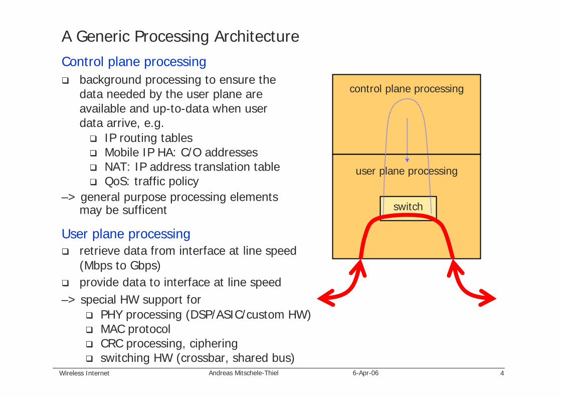
A Generic Processing ArchitectureControl plane processing
background processing to ensure thedata needed by the user plane areavailable and up-to-data when userdata arrive, e.g.
IP routing tablesMobile IP HA: C/O addressesNAT: IP address translation tableQoS: traffic policy
–> general purpose processing elementsmay be sufficent
control plane processing
user plane processing
User plane processingretrieve data from interface at line speed(Mbps to Gbps)provide data to interface at line speed
–> special HW support forPHY processing (DSP/ASIC/custom HW)MAC protocolCRC processing, cipheringswitching HW (crossbar, shared bus)
switch

Wireless Internet 5Andreas Mitschele-Thiel 6-Apr-06
Example: IP Router Architectures
Router functionsRouter generationsDesign issues for high-speed routersSwitching fabrics for routersDesign of Cisco GSR 12XXX routers

Wireless Internet 6Andreas Mitschele-Thiel 6-Apr-06
Functions of an IP Router
Layer 1 (inbound): signal regenerationbit and frame synchronisation
Layer 2 (inbound): header eliminationCRC
Layer 3:route processing (static/dynamic)packet forwarding
protocol version check header & packet length checkTTL test and decrementCRC computation & recomputationdestination addressQoS handling (classification, etc.)fragmentation (MTU limits)route lookuphandling of packets to router itself
special servicesauthentication & authorisationpacket filteringverification of source IP addressnetwork managementTCP congestion control (RED)
Layer 2 (outbound): header generationCRC computationmedia access coordination
Layer 1 (outbound): signal generationbit and frame synchronisation
PhyMACLLC
PhyMACLLC
IP

Wireless Internet 7Andreas Mitschele-Thiel 6-Apr-06
First Generation Routers (Centralized Architecture)
CPU Memory
DMA
L1/MAC
DMA DMA
L1/MAC L1/MAC
Bus
Electrical limitations of shared bus systems to about 20 Gbps throughputmax line rate = 10 Gbps/number of line cards
Limits:packet data aretransmitted twice overthe shared buscentral CPU has to process all packetsflowing through theroutermemory intensive operations (table lookups) limit theeffectiveness of CPU updates (limit of memoryaccesses)
Line Card Line Card Line Card

Wireless Internet 8Andreas Mitschele-Thiel 6-Apr-06
Second Generation Routers (Distributed Processing)
CPU Memory
DMA DMA DMA
L1/MAC L1/MAC L1/MAC
Route cacheCPU
Memory Memory Memory
LineCards
Cacheupdate
Bus
Route cacheCPU
Route cacheCPU
Two extensions to first generation routers:routing table entries are cached in line cardsdistributed forwarding engines (header processing) in line cards (or separate)
Prospacket data aretransmitted once onlyover the shared busparallel/distributedpacket (header) processing in forwarding engines
Constraffic throughputunpredictable due to caching (slow vs. fast path) shared bus is still thebottleneck

Wireless Internet 9Andreas Mitschele-Thiel 6-Apr-06
Second Generation Routers: Line Card

Wireless Internet 10Andreas Mitschele-Thiel 6-Apr-06
Third Generation Routers (Switch-based)
Line Card
Routing Table
Route Processor
Line Card
Line Card
...
Switch is no longer the bottleneck –> new bottleneck is packet processing (user plane)
–> employ specialized HW in line cards
user plane
control planemaintenancerouting protocols (RIP, OSPF, BGP)protocol error handlingnetwork managment

Wireless Internet 11Andreas Mitschele-Thiel 6-Apr-06
Third Generation Routers (Switch-based, Fully Distributed)
Line Card
Routing Table
Route Processor
Line Card
Line Card
...
ForwardingEngine
ForwardingEngine
ForwardingEngine
...
Headers are sent to forwarding engine for processing and returned to inbound line card for forwarding
Switch is no longer the bottleneck –> new bottleneck is packet processing (user plane)
–> use distributed forwarding engines

Wireless Internet 12Andreas Mitschele-Thiel 6-Apr-06
Switch Fabrics Design
Switch fabric designsshared medium (bus, ring, dual-bus)shared memory (dual port)distributed output bufferspace division – crossbar
Switch fabrics requirements:packet transfermulticastingfault toleranceloss and delay priorities on traffic
Basic functions:packet transferpacket duplication (multicast)packet scheduling (QoS)packet discarding (QoS, overloadhandling)congestion monitoring and control
Switch fabric design criteria:throughputpacket losspacket delaysamount of bufferingcomplexity of implementation

Wireless Internet 13Andreas Mitschele-Thiel 6-Apr-06
Switch Fabrics: Shared Medium (Bus)
Discussion:address filters and output buffers must operate at N times the speed of a portphysical limit of speed of bus, address filters and output buffers-> limitation of total bandwidthoutput queueing supports optimal throughputno sharing of buffers (i.e. use of output buffers) -> more memory requirednatural implementation of multicast and broadcast
......
Line Card
Line Card
Line Card
Line Card
Line Card
Line Card
OutputInputOperation
time-sharing of medium(TDM)
each output monitorsaddress tag to identifyrelevant packets

Wireless Internet 14Andreas Mitschele-Thiel 6-Apr-06
Switch Fabrics: Shared Memory
Discussion:physical limit of access time of RAM (read/write at speed N times the speed of ports)processing of central controller at packet rate (assume the controller has to handle multiple priority classes and complicated packet scheduling)sharing of buffers (output buffers) -> efficient use of memory due to statistical sharingmulticast requires extra circuitry (multiple reads, or multiple copies in memory)
Operation:kind of outputqueueingapproach (all output buffersbelong to sharedmemory pool)
......
Line Card
Line Card
Line Card
Line Card
Line Card
Line Card
OutputInput
SharedM
emory
Controller
Popular switcharchitecture (efficentmemory usage withunbalanced traffic)

Wireless Internet 15Andreas Mitschele-Thiel 6-Apr-06
Switch Fabrics: Distributed Output-Buffered Switch
Output buffering:immediate placement of packets in output buffers-> optimal throughput and delay-> better control of latency (QoS guarantees)
Quadradic N2 growth of buffers -> limit to number of ports N
AF AF AF
1 N
NAF AF AF Address
Filter
Buffers
12
N
1 2 N 21

Wireless Internet 16Andreas Mitschele-Thiel 6-Apr-06
Switch Fabrics: Crossbar Switch (Input-buffered Switch)
Non-blocking switchNumber of cross points N X NComplexity increases with increase in ports
N X N Crossbar Switch
Discussion:input bufferingcrossbar runs at line ratehighly scalable architecture
Problems:Head-of-line (HOL) blocking
12
N
1 2 N

Wireless Internet 17Andreas Mitschele-Thiel 6-Apr-06
Problem with Input Buffer: Head-of-Line Blocking (HOL)
1 1 2 1
1 1 1 1
Output 1
Output 2
Head of line is blocked due to blocked output port of crossbar-> all following packets to other directions are blocked as well
Solutions:increase speed of switch fabric (beyond line speed: factor 2 to 5 depending on traffic characteristics)Virtual Output Queues (VOQs)

Wireless Internet 18Andreas Mitschele-Thiel 6-Apr-06
Virtual output queuing (VOQ)
Multiple input queues operate (one per output port) as virtual output queues

Wireless Internet 19Andreas Mitschele-Thiel 6-Apr-06
Multicast support
Make duplicate copies and send as unicast traffic
Use separate multicast queue for each input line (with/without fanout splitting)

Wireless Internet 20Andreas Mitschele-Thiel 6-Apr-06
High-end IP router seriesswitch up to 16 input lines simultaneouslyAggregate switching speed is 38.4 Gbps
Up to 80 Gbps system bandwidth 8-15 line cards5 switch fabric slots2.5 Gbps full duplex line between line cards and switching fabric
Switch fabric card redundancyVirtual output queues (VOQ) to eliminate head-of-line (HOL) blockingMulticast support with fanout splittingFixed packet length (cell) switching with cell size of 64 bytes (8 byte header,48 byte payload and 8 byte CRC)
Cisco 12016 GSR Cisco 12xxx GSR Series

Wireless Internet 21Andreas Mitschele-Thiel 6-Apr-06
Summary of Design Consideration for Fast Routers
Fixed vs. variable length packetsfixed length packet: + increased efficiency+ high throughput+ simple scheduling algorithm– fragmentation and reassembly
Input buffer or output bufferInput buffer only– low throughput– complex scheduling algorithm
(switch and line contention)+low cost Output buffer only – switching speed greater than
aggregate input speed+low cost
Solution:-> Use both input and output buffers
Buffer management and QoSMulticast traffic supportRoute caching or replication
Why high-performance routers?high bandwidthhigh link speedsQoS requirementshigher layer processing requirements – “higher-layer switching”
firewallVPNmobility supportsession management and QoS

Wireless Internet 22Andreas Mitschele-Thiel 6-Apr-06
So, now we have seen the architecture of IP routers ... How do the network elements of a UMTS system look like?
Radio access network (UTRAN) employs ATM transportCore network (CN) employs IP transport in
What´s the difference from an IP router or an ATM switch?higher-layer protocol processing
complex processing (states per session)mobility (GTP, MobileIP, ...)session, QoS, radio resource managementaccountingsecuritymulticast (paging support)
rather moderate data rates for most network elements (up to 1 Gbps for SGSN, 300 Mbps for RNC)flexibility required (software updates)
=> resembles a corporate firewall to some extent (SGSN, GGSN)lots of different interfaces supportedradio interface processing in RNC: L1-3 processing
complex processinginteraction between layers

Wireless Internet 23Andreas Mitschele-Thiel 6-Apr-06
UMTS Protocol Architecture (packet switched)
Q2150.1
SGSNSGSNRNCRNCNode BNode B
Control Plane User Plane Transport Plane CommonControl Plane User Plane Transport Plane Common
MM
SM
MAC
Phy-up
PHY
codec
RRC
RLC
PMM
SM
MAC
Phy-up
PHY
RRC
IP
PDCP
RLC
SSCOP
NBAP
AAL5
SSCOP
ALCAP
AAL5
SSCF SSCF FP
AAL2 AAL2 AAL5 AAL5
SSCF
RLC
MAC
Phy-up SCCP
FP
RRC
ATM
E1
NBAP
AAL5 AAL2
SSCOP
MTP3-b
SSCF-N
SCCP
RANAP
RRC
ATM
STM-1
GTP-U
UDP
PDCP
ALCAP
STC.2
SSCF-UNI
SSCOP
IP
RLC
MAC
Phy-up
FP
AAL5
ATM
E1
FP
AAL2
SSCOP
ALCAP
AAL5
SSCOP
NBAP
AAL5
SSCF SSCF
PHY
ATM
E1/ STM-1
AAL2 AAL5
NBAP
PHY
ALCAP
SSCOP
STC.2
SSCF-UNIFP
SSCOP
MTP3B
AAL5
SSCF
Q2150.1
Q2150.1
Iu UP
ATM
E1
AAL2
SSCOP
MTP3B
AAL5
SSCF
SCCP
SM
MM
RANAP
SSCOP
MTP3-b
SSCF-N
SCCP
PMM
SM
ATM
STM-1
AAL5
IP
GTP-U GTP-C
UDP
L1
L2
SSCOP
MTP3B
AAL5
SSCF
Q2150.1
Q2150.1
IP
GTP-C
L1
GTP-U
UDP
L2
IP
GGSNGGSNUu Iub Iups Gn
Serving GSN (SGSN) functions
session management
mobility management
subscriber database management(interface with HLR)
maintenance of charging data (for radio network usage)
IP-based transport of user data
IP/SS7-based signaling transport

Wireless Internet 24Andreas Mitschele-Thiel 6-Apr-06
Example: UMTS SGSN (Serving GPRS Support Node)
Let´s take a look at the requirements:
Capacity
1M PDP contexts (i.e. IP addresses)
0.5M attached subscribers
serving > 16 RNCs
> 500 Mbps data throughput
> 180k PDP activations per busy hour
efficient subscriber data management
Reliability and fault tolerance
uninterrupted service in case of failure and overload
Various interfaces STM-1, POS (Packet Over SONET), Gigabit Ethernet
Wealth of service features: SMS, supplementary services, IN, etc.
Easy and simple maintenance
Notes:
PDP contexts vs. attached subscribers indicates that
• each subscriber has one or morePDP contexts (i.e. an IP address)PDP context may be active or inactive
• PDP context is available (active orinactive) most of the time while mobile is turned on
Data throughput vs. PDP contexts indicates that
• average throughput of 500 bps per PDP context or 1kbps per subscriber
• time to set up 1M PDP contexts is 5.5 hours (this is required after a system failure; assumption constantdistribution)

Wireless Internet 25Andreas Mitschele-Thiel 6-Apr-06
Example: Generex-2000 SGSN from LG Electronics, Korea
Implementation principles:
Separation of control and user plane
control plane: controller units (main processing boards)
user plane: interface units
Scalability: modular architecture for flexible capacity increase
Reliability
1+1 redundancy for main processors, switch, ATM adaptation cards and SS7 cards
N+1 redundancy for line cards
Performance: dedicated processors for control and user plane
Interoperability: compliance to standards (interface)

Wireless Internet 26Andreas Mitschele-Thiel 6-Apr-06
Generex-2000 SGSN – System Architecture Components
Interface units
InterfacesFast Ethernet (Gn, Gp)GigabitEthernet (Gn, Gp)Packet over Sonet (Gn)ATM STM-1 (Gn)SS7
UMTS user plane processingGTP-U (RNC and GGSN)
Interface boardsNetwork processor (Motorola C-5)
GTP forwardingQoS handlingpacket forwarding
Host processor (PowerPC 8260 – 603e core)control of network processordata collection for charging and statistics
Special SS7 interface boards (connect to MSC/VLR, HLR, EIR, etc.)
ATM switch20 Gbyte back plane
Controller units
Interface units
ATM switch
line processing(inbound/outbound)
Datastorage

Wireless Internet 27Andreas Mitschele-Thiel 6-Apr-06
Generex-2000 SGSN – System Architecture Components
Data storage devicescollection of charging and statistics
Controller units
Interface units
ATM switch
line processing(inbound/outbound)
Controller unitsmanagement of interface units(resources, etc)8 pairs of main processors (1+1)Motorola PowerPC 750 RISC processorproprietary RT operating systemdifferent software on identical boards
system operation and management, charging and statisticsRNC interconnection, session management, PDP context data base, Iu-PS signaling connection managmentGTP-c message processing MAP, BSSAP+mobility managementsubscriber data base managementmobility management context management
Datastorage

Wireless Internet 28Andreas Mitschele-Thiel 6-Apr-06
Motorola 8260 PowerQUICC II
integrated communication microprocessor designed for telecommunicationsand networkingfloating point supportHW support for numerous interfaces (ATM, T1/E1, 10/100 MbpsEthernet, ...)
two main components (dual-processor architecture)
embedded PowerPC 603 (G2) microprocessor core (RISC, superscalar)Communications Processor Module (CPM)
CPM offloads peripheral tasks from the PowerPC coreCPM simultaneously supports various interfaces

Wireless Internet 29Andreas Mitschele-Thiel 6-Apr-06
Generex-2000 SGSN – Performance
Generex-2000 SGSNup to 16 RNCs served500k subscribers1M PDP contexts (11 contexts per subscriber)500k PDP activations per busy hour3.5 Gbps data throughput3010 mobility managment transactions per second0.2-0.3 sec delay for routing area update0.2-0.3 sec delay for searching mobile management context information1 Mill. SMSs per busy hourfootprint: 2 cabinets

Wireless Internet 30Andreas Mitschele-Thiel 6-Apr-06
UMTS Protocol Architecture (packet switched)
Q2150.1
SGSNSGSNRNCRNCNode BNode B
Control Plane User Plane Transport Plane CommonControl Plane User Plane Transport Plane Common
MM
SM
MAC
Phy-up
PHY
codec
RRC
RLC
PMM
SM
MAC
Phy-up
PHY
RRC
IP
PDCP
RLC
SSCOP
NBAP
AAL5
SSCOP
ALCAP
AAL5
SSCF SSCF FP
AAL2 AAL2 AAL5 AAL5
SSCF
RLC
MAC
Phy-up SCCP
FP
RRC
ATM
E1
NBAP
AAL5 AAL2
SSCOP
MTP3-b
SSCF-N
SCCP
RANAP
RRC
ATM
STM-1
GTP-U
UDP
PDCP
ALCAP
STC.2
SSCF-UNI
SSCOP
IP
RLC
MAC
Phy-up
FP
AAL5
ATM
E1
FP
AAL2
SSCOP
ALCAP
AAL5
SSCOP
NBAP
AAL5
SSCF SSCF
PHY
ATM
E1/ STM-1
AAL2 AAL5
NBAP
PHY
ALCAP
SSCOP
STC.2
SSCF-UNIFP
SSCOP
MTP3B
AAL5
SSCF
Q2150.1
Q2150.1
Iu UP
ATM
E1
AAL2
SSCOP
MTP3B
AAL5
SSCF
SCCP
SM
MM
RANAP
SSCOP
MTP3-b
SSCF-N
SCCP
PMM
SM
ATM
STM-1
AAL5
IP
GTP-U GTP-C
UDP
L1
L2
SSCOP
MTP3B
AAL5
SSCF
Q2150.1
Q2150.1
IP
GTP-C
L1
GTP-U
UDP
L2
IP
GGSNGGSNUu Iub Iups Gn
Radio Network Controller (RNC) functionsradio resource managementmobility management and handoversystem access controltransfer of user data (UTRA protocols: upperPHY, L2, L3; ATM/IP transport)

Wireless Internet 31Andreas Mitschele-Thiel 6-Apr-06
Example: Fujitsu RNC
ATM
sw
itch
upper PHY(combining/splitting)
MACc/sh
Signaling transport (RLC, ...)
Bandwidth controller
(AAL2)
Controller (RLC, RANAP, NBAP, RNSAP, connection management)
Externalinterfacesto nodeBand MSC
ATM switching coreHW specialized for applicationDSP-based user plane processing

Wireless Internet 32Andreas Mitschele-Thiel 6-Apr-06
Fujitsu RNC – Splitting/Combining Data Processing (SCT)
Function

Wireless Internet 33Andreas Mitschele-Thiel 6-Apr-06
Fujitsu RNC – Splitting/Combining Data Processing (SCT)
Function
Hardware

Wireless Internet 34Andreas Mitschele-Thiel 6-Apr-06
Fujitsu RNC – UpperPHY and MAC-c/sh Processing Hardware
MAC-c/sh functionsscheduling and priority handlingtransport format set (TFC) selectiontransport channel type switchingpaging
MAC-c/sh board

Wireless Internet 35Andreas Mitschele-Thiel 6-Apr-06
Example: Ericsson RNC3810 – Hardware Structure
SXB: switch extension boardSCB: switch core board: ATM switch
TUB: timing unit boardET: exchange terminal boards (interface boards)
SPB: special-purpose processor board (user plane)GPB: general-purpose processor board (control plane)
RNC is based on ATM platformImportant features
standard middleware (IP, CORBA)Reliability: hot-standby (1+1) and N+1

Wireless Internet 36Andreas Mitschele-Thiel 6-Apr-06
Ericsson RNC3810 – Hierarchical (Logical) Structure
General-purpose Processor BoardsN+1 processing farmIub signaling
General-purpose Processor BoardsN+1 processing farmIub signaling
General-purpose Processor Boards central control6 boardshot standby (1+1)OAMIu, Iur signaling
General-purpose Processor Boards central control6 boardshot standby (1+1)OAMIu, Iur signaling
Special Processor PoolN+1 processing farmuser plane processing
Special Processor PoolN+1 processing farmuser plane processing

Wireless Internet 37Andreas Mitschele-Thiel 6-Apr-06
Example: Intel RNC Platform (under development)
Intel is developing a hardware platform (HW components) to implement UMTS RNCs
Important features:Backplane based on Gigabit-Ethernet (user plane) instead of ATM switch Fast-Ethernet for control planesupport for IXP 2400/2800 network processors on line cards

Wireless Internet 38Andreas Mitschele-Thiel 6-Apr-06
Intel RNC Platform – Cards Control and Applications Card: controls the entire system and performs application-level functions complementary to the other line cardsdual Intel® Xeon™ processorGigabit Ethernet connectivity to thebackplane front-panel Ethernet ports for management, databases, or external application servers redundant control card
Radio Access Network (RAN) Line Card: Node B controller four channelized OC-3 connections (twocards offering eight channelized OC-3 ports for a total 1.2 Gbps of Node B ingress bandwidth)
Core Network (CN) Card: four OC-12 connections to the back-end circuit-switched and packet-switched infrastructure
Real Time Unit (RTU) Line Card: implements real-time user stream processing
Ethernet Switching Module: 48 Gbps Ethernet switching fabric in a dual-star configuration with centralized switching
Wireless Internet 39Andreas Mitschele-Thiel 6-Apr-06
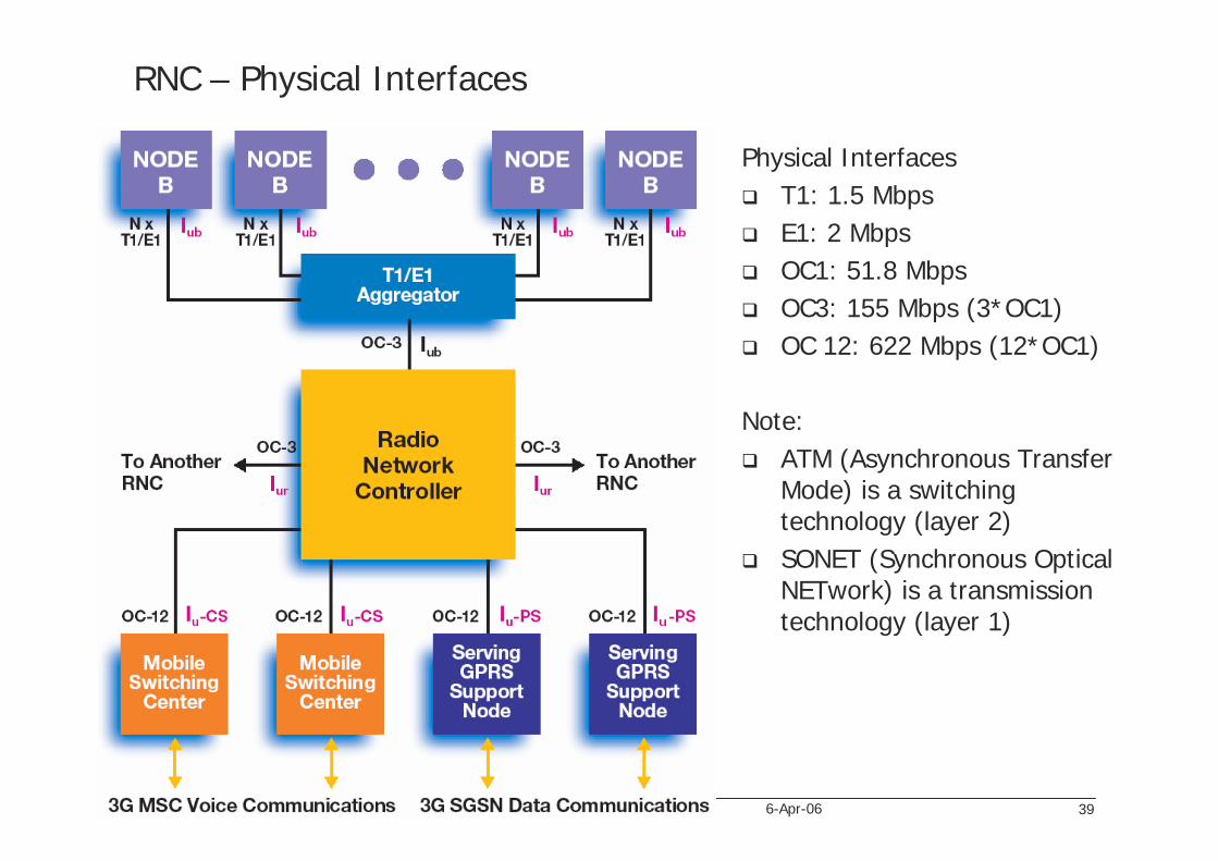
RNC – Physical Interfaces
Physical InterfacesT1: 1.5 MbpsE1: 2 MbpsOC1: 51.8 MbpsOC3: 155 Mbps (3*OC1)OC 12: 622 Mbps (12*OC1)
Note:ATM (Asynchronous Transfer Mode) is a switching technology (layer 2)SONET (Synchronous Optical NETwork) is a transmission technology (layer 1)

Wireless Internet 40Andreas Mitschele-Thiel 6-Apr-06
Intel RNC Platform – User Plane Processing (Uplink)
(1)
Iub
tran
spor
t(2
) Iu
b FP
&
uppe
rPH
Y
(3) RLCMAC
SGSN NodeBSSCOP
NBAP
AAL5
SSCOP
ALCAP
AAL5
SSCF SSCF FP
AAL2 AAL2 AAL5 AAL5
SSCF
RLC
MAC
Phy-up SCCP
FP
RRC
ATM
E1
NBAP
AAL5 AAL2
SSCOP
MTP3-b
SSCF-N
SCCP
RANAP
RRC
ATM
STM-1
UDP
ALCAP
STC.2
SSCF-UNI
SSCOP
IP
RLC
MAC
Phy-up
FP
AAL5(1)
(2)
(3)
(4)GTP-UPDCP
(4)
(4)
PDCP
GTP
-UIu
tra
nsp.
In order to minimize the required switch capacity, the number of transfers of data over the switch should be minimized

Wireless Internet 41Andreas Mitschele-Thiel 6-Apr-06
Intel RNC Platform
Control and Applications CardRANAP, RNSAP, RRC processingXeon processor (server)

Wireless Internet 42Andreas Mitschele-Thiel 6-Apr-06
Intel RNC Platform
Radio Access Network Line CardATM or IP transportIXP 2400 network processor (8 microengines, 5.4 GIPS)4 OC-3 interfaces

Wireless Internet 43Andreas Mitschele-Thiel 6-Apr-06
Intel RNC Platform
RTU Line Card
RLC/MAC processingIXP 2800 network processor (16 microengines, 22.4 GIPS at 1GHz)estimated board capacity is 200 Mbps (including encryption)

Wireless Internet 44Andreas Mitschele-Thiel 6-Apr-06
Intel IXP 2800 Network Processor
Xscale Core (StrongArm successor)16 microengines (ALU, Registers)multi-level memory hierarchymultiple interprocessor communication channels

Wireless Internet 45Andreas Mitschele-Thiel 6-Apr-06
IXP 2800 Microengine (ME)
RISC procesor (32-bit data)8 HW threads per ME6-stage pipelinebit, byte and longword operationsno floating-point unitno HW caching

Wireless Internet 46Andreas Mitschele-Thiel 6-Apr-06
Example: UMTS Base Station ProcessingDevelopment considerations:
ASIC development cycle is about 36 months high cost and time for redesigndevelopment costs of 100M US$inflexible to changes high power efficencylow cost per HW unit
FPGA or DSP development cycle is about 28 months for FPGA, 23 months for DSPflexible to changeslow power efficiency (esp. for FPGAs)higher cost per HW unit

Wireless Internet 47Andreas Mitschele-Thiel 6-Apr-06
Example: Structure of UMTS Base Band Processing

Wireless Internet 48Andreas Mitschele-Thiel 6-Apr-06
Summary of Architectural Design Decisions
Hardware issuesSpecialized HW
fastlow cost per unit (for large quantities)high development costhigh dependence on HW provider (especially where special HW features are used, e.g. microcoding of network processors)
General-purpose HWquick change of HW (in theory)easier to migrate to new HW generations (HW updates)smaller performancehigher power consumption
Software issues – common practicebuy and adapt commercial software (common protocol implementationsavailable as source code for various operation systems and HW platforms)infrastructure provider focus on non-standardized parts (e.g. algorithms)alignment between HW and SW provider needed (standardized HW and standardized SW platforms)

Wireless Internet 49Andreas Mitschele-Thiel 6-Apr-06
ReferencesJames Aweya: On the design of IP routers – Part 1: Router architectures. Journal of Systems Architecture 46, Elsevier, pp483-511, 2000James Aweya, “IP Router Architectures – An overview”http://www.cs.virginia.edu/~cs757/papers/awey99.pdfCisco router products: http://www.cisco.com/en/US/products/hw/routers/index.htmlCisco router white paper: http://www.cisco.com/en/US/products/hw/routers/ps167/products_white_paper09186a0080091fdf.shtmlhttp://www.erg.abdn.ac.uk/users/gorry/course/inet-pages/router-opn.htmlNick McKeown, “A Fast Switched Backplane for a Gigabit Switched Router”http://www.bcr.com/bcrmag/1997/12/mckeown.asphttp://www.cs.ualberta.ca/~macg/C605/Routers/Cisco_12000/Fabric.htmlS. Keshav, R. Sharma, “Issues and Trends in Router Design”http://www.cs.cornell.edu/skeshav/papers/routertrends.pdfSwitch architectures: http://www2.rad.com/networks/1994/pak-swi/swarch.htmVarious talks on routers: http://klamath.stanford.edu/~nickm/M. Jang, C. Lee, H. Kim, et. al: Development of a Commercial SGSN System for IMT2000 UMTS. LG Electronics, Korea, 2002.K.Ito, T Kumagai, K Harada, T. Sonobe, T.Tomita, E. Ikeda: Radio Network Control System. Fujitsu Sci. Tech. J. 38(2), 2002.B. Gestner, B. Persson: RNC3810 – Ericsson´s first WCDMA radio network controller. Ericsson Review, No. 2, 2002. (see http://www.ericsson.com)R. Baines, D. Pulley: A Total Cost Approach to Evaluationg Different Reconfigurable Architectures for Baseband Processing in Wireless Receivers. IEEE Communications Magazine, Jan. 2003.Intel Cooperation: 3G Wireless Radio Network Controller. Product Information 2003.