TECHNICAL SPECIFICATIONS & STANDARD EQUIPMENT LIST
13
TECHNICAL SPECIFICATIONS & STANDARD EQUIPMENT LIST
Transcript of TECHNICAL SPECIFICATIONS & STANDARD EQUIPMENT LIST
TECHNICAL SPECIFICATIONS &
STANDARD EQUIPMENT LIST
TECHNICAL SPECIFICATIONS &
STANDARD EQUIPMENT LIST
Note: The “400S Seaplane” is a marketing definition for branding purposes only and does not constitute a new Type Design. Information contained within this report is proprietary to Viking
Air Limited and provided for reference purpose only. Provision of this information does not constitute any form of contractual commitment between Viking Air Limited and the recipient. No
warranty or representation is made to the accuracy or applicability of the information contained herein, and data is subject to change without notice. DOCUMENT REVISION: 02-02-16
Aircraft Overview
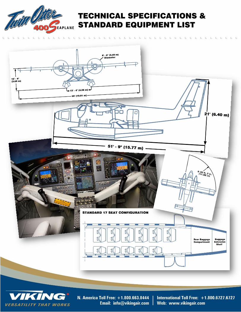
The Viking 400S Twin Otter (“400S”) is an all-metal, high wing
monoplane, powered by two wing-mounted turboprop engines,
driving three-bladed, reversible pitch, fully feathering propellers.
The aircraft carries a pilot, co-pilot, and up to 17 passengers in
standard configuration with a 19 or 15 passenger option. The
aircraft is a floatplane with no fixed landing gear.
The 400S is an adaptation of the Viking DHC-6 Series 400 Twin
Otter (“Series 400”). It is specifically designed as an economical
seaplane for commercial operations on short to medium
segments.
The Series 400 is an updated version of the Series 300 Twin
Otter. The changes made in developing the Series 400 were
selected to take advantage of newer technologies that permit
more reliable and economical operations. Aircraft dimensions,
construction techniques, and primary structure have not
changed.
The aircraft is manufactured at Viking Air Limited facilities in
Alberta and British Columbia, Canada. The Type Certificate (A-
82 from Transport Canada) is held by Viking Air Limited.
The aircraft is optimized for quick turnaround between cycles,
featuring double swing out doors at the aft passenger entrance
with direct access through the cabin to the rear baggage
compartment for quick loading. A separate avionics-dedicated
battery also allows the cockpit screens to remain live during short
turns. The avionics have been adapted for VFR operations and
feature a Honeywell “Super-Lite” integrated suite. Avionics
upgrade options available for IFR operation as outlined in Section
20.
With the 400S specification, particular attention has been paid to
the unique challenge corrosion causes in water-based
operations; corrosion-resistant packages for the airframe, power
plant and fuel systems have been incorporated as standard
equipment, along with additional draining, sealing, battery
relocation, and prevalent use of corrosion-resistant materials
throughout. The airframe has a corrosion prevention primer
applied, and electrical connectors and sensors exposed to water
have been upgraded.
The aircraft is delivered with two Pratt and Whitney PT6A-27
engines that incorporate platinum coated CT blades.
The 400S will be supplied with new generation composite floats
that reduce the overall aircraft weight (when compared to Series
400 Twin Otters configured for complex utility or special mission
operations). The weight savings allows the standard 400S to
carry a 17 passenger load 150 nautical miles with typical
reserves, at an average passenger and baggage weight of 191
lbs. (86.5 kg.).
1. General Description
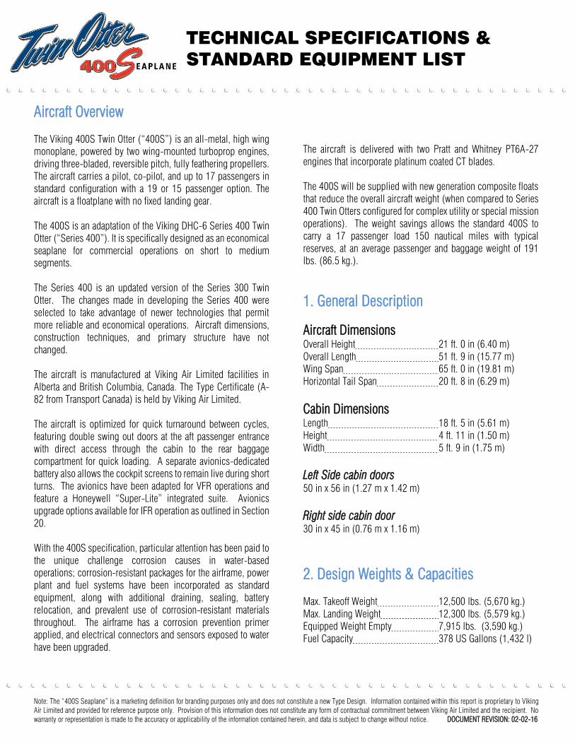
Aircraft Dimensions
Overall Height 21 ft. 0 in (6.40 m)
Overall Length 51 ft. 9 in (15.77 m)
Wing Span 65 ft. 0 in (19.81 m)
Horizontal Tail Span 20 ft. 8 in (6.29 m)
Cabin Dimensions
Length 18 ft. 5 in (5.61 m)
Height 4 ft. 11 in (1.50 m)
Width 5 ft. 9 in (1.75 m)
Left Side cabin doors
50 in x 56 in (1.27 m x 1.42 m)
Right side cabin door
30 in x 45 in (0.76 m x 1.16 m)
2. Design Weights & Capacities
Max. Takeoff Weight 12,500 lbs. (5,670 kg.)
Max. Landing Weight 12,300 lbs. (5,579 kg.)
Equipped Weight Empty 7,915 lbs. (3,590 kg.)
Fuel Capacity 378 US Gallons (1,432 l)
TECHNICAL SPECIFICATIONS &
STANDARD EQUIPMENT LIST
Note: The “400S Seaplane” is a marketing definition for branding purposes only and does not constitute a new Type Design. Information contained within this report is proprietary to Viking
Air Limited and provided for reference purpose only. Provision of this information does not constitute any form of contractual commitment between Viking Air Limited and the recipient. No
warranty or representation is made to the accuracy or applicability of the information contained herein, and data is subject to change without notice. DOCUMENT REVISION: 02-02-16
3. General Arrangement
TECHNICAL SPECIFICATIONS &
STANDARD EQUIPMENT LIST
Note: The “400S Seaplane” is a marketing definition for branding purposes only and does not constitute a new Type Design. Information contained within this report is proprietary to Viking
Air Limited and provided for reference purpose only. Provision of this information does not constitute any form of contractual commitment between Viking Air Limited and the recipient. No
warranty or representation is made to the accuracy or applicability of the information contained herein, and data is subject to change without notice. DOCUMENT REVISION: 02-02-16
4. Performance
The following performance data is intended to demonstrate the aircraft's capability in a typical flight profile.
SFAR23 Takeoff and Landing Distances
Takeoff dist. to 50 ft. (15.2m) at MTOW 2,247 ft. (685 m)
Landing dist. from 50 ft. (15.2m) at MLW 1,741 ft. (531 m)
ISA+10 Maximum Cruise Speeds, TAS
2,000 ft. 153 kt
4,000 ft. 154 kt
8,000 ft. 156.5 kt
Enroute Rate of Climb at Sea Level
Both engines at max climb power 1,347 ft./min
Service Ceiling (Rate of Climb 100 ft/mm)
Both engines max climb power 22,000 ft. (6,706 m)
One engine max cont. power 4,500 ft. (1,372 m)
Payload Range (incl. two pilots totaling 380 lbs.)
Payload for 50nm range 3,636lbs. (1,649 kg.)
Payload for 100nm range 3,429lbs. (1,555 kg.)
Payload for 150nm range 3,245lbs. (1,472 kg.)
Payload for 200nm range 3,039lbs. (1,378 kg.)
Performance Assumptions Used
All takeoff distances are based on both engines operating at takeoff power throughout. The takeoff and landing distances are given at
sea level, zero wind and calm water surface.
Payload range data is based on the following assumptions:
o Cruise at maximum cruise power at 8,000 ft. (2,438 m) for both 150 nm and 225 nm segments, and at 5,000 ft. (1,524 m) for
both 50 nm or 100 nm segments,
o Climb at maximum power and descent at 500 feet / minute,
o Taxi, takeoff and landing fuel allowance of 35 lbs. (16 kg.),
o Fuel reserve of 300 lbs. (136 kg.); and
o Fuel consumption based on engine manufacturer's specifications.
Operational Empty Weight is 8,305 lbs. (3,767 kg.) and assumes a standard aircraft fitted with 17 commuter seats operating with a
crew of 2 at 190 lbs. (86.2 kg.) each.
All performance data assumes ISA+10 conditions.
TECHNICAL SPECIFICATIONS &
STANDARD EQUIPMENT LIST
Note: The “400S Seaplane” is a marketing definition for branding purposes only and does not constitute a new Type Design. Information contained within this report is proprietary to Viking
Air Limited and provided for reference purpose only. Provision of this information does not constitute any form of contractual commitment between Viking Air Limited and the recipient. No
warranty or representation is made to the accuracy or applicability of the information contained herein, and data is subject to change without notice. DOCUMENT REVISION: 02-02-16
5. Fuselage
With the exception of the conical nose section, the fuselage
primary structure is of an all-metal conventional construction with
frames, stringers, and skin all made of aluminum alloy.
The external surfaces of the standard aircraft are primed with a
chromated epoxy primer and are ready for paint application. The
airframe has a corrosion prevention primer applied.
The fuselage is comprised of five permanently attached sections:
the nose section; the flight compartment; the fuselage forward
cabin; the fuselage rear cabin; and the rear fuselage.
Nose Section
The nose section, manufactured in three sections, consists of a
nose cap, center, and rear sections. The main center section is a
carbon fibre composite assembly with a foam core, and forms the
nose compartment. The upward and outward-opening nose
compartment access door, located on the left side of the nose
section, is equipped with a prop rod to hold the door open and
two latches, the forward of which can be locked externally by key.
Flight Compartment Section
The flight compartment extends from the forward bulkhead aft to
a flight compartment / cabin bulkhead and consists of a
conventional skin and stringer frame bulkhead structure. Two
forward, outward-opening doors, one on the left and one on the
right, are provided for external access to the flight compartment.
Bird impact-resistant plastic windshield panels are standard.
Access to the flight compartment from the cabin is provided by a
central doorway in the flight compartment / cabin bulkhead.
Forward & Rear Cabin Sections
The forward fuselage section extends from the flight compartment
/ cabin bulkhead to a frame forward of the left door surround, and
the rear section extends from this frame aft to the rear baggage
compartment. These sections form one large main cabin section.
The cabin section consists of floor, side and roof panel
assemblies. The roof panels are stiffened by longitudinal
stringers, with the exception of the center portion which is a
honeycomb core sandwich panel.
The left cabin entrance comprises two swing out door sections.
The doors can be locked and unlocked externally and internally.
Two plug-type emergency exits are provided in the main cabin:
one in each side panel at the forward end of the cabin. A single
swing-out exit door is located on the right side of the aft cabin
section.
Eight acrylic plastic windows are installed on the right side of the
cabin: one in the forward emergency exit, one in the right cabin
door, and six in the side panel. Seven similar windows are
installed on the left side of the cabin: one in the forward
emergency exit, one on the cabin door and five in the side panel.
The complete main cabin has a total usable volume of
approximately 384 cubic feet (10.9 m3
).
Rear Fuselage Section
The rear fuselage section, which contains the rear baggage
compartment, extends aft in a gradual taper from the frame
forward of the left door surround. A cargo net arrangement
separates the main passenger cabin from the baggage
compartment.
6. Wings
The wing consists of the left and right mainplanes, which are
rectangular in plan form and of constant section. Each mainplane
is attached to the fuselage structure, at roof level, by two bolts
through fork and lug fittings at the front and rear spars, and is
supported by a lift strut having single bolt attachments at each
end. A double-slotted, full-span flap/aileron system is installed
at each mainplane trailing edge.
Each wing structure is a box of constant section, manufactured
from high strength aluminum alloy, and consists of main and rear
spars, a short front spar at the root end, and top and bottom skin
panels.
Both mainplane leading edges are hinged between the fuselage
and nacelle to permit access for servicing. Access is also
provided to the mainplane interior for the maintenance of flap and
aileron control systems. Five hinge arms are provided on each
mainplane rear spar to carry the flap/aileron system.
The wing tips, which are removable for servicing and
maintenance, have internal lightning protection bonding strips
that are secured to each wing structure to provide a ground for
electrical discharge. Electrical wiring to each wing tip is routed
through conduit tubing for protection.
TECHNICAL SPECIFICATIONS &
STANDARD EQUIPMENT LIST
Note: The “400S Seaplane” is a marketing definition for branding purposes only and does not constitute a new Type Design. Information contained within this report is proprietary to Viking
Air Limited and provided for reference purpose only. Provision of this information does not constitute any form of contractual commitment between Viking Air Limited and the recipient. No
warranty or representation is made to the accuracy or applicability of the information contained herein, and data is subject to change without notice. DOCUMENT REVISION: 02-02-16
7. Empennage
The tail group is comprised of a horizontal stabilizer, an elevator,
a vertical stabilizer, and a rudder.
Horizontal Stabilizer
The horizontal stabilizer is a one-piece unit, consisting of front
and rear full span spars and full span top and bottom skin/stringer
panels. Hinge arms extending rearward from the rear spar carry
the elevator.
Elevator
The elevator consists of left and right-hand units, joined at the
center by a torque tube. Each elevator unit is of a conventional
all-metal construction, comprising two span-wise spars with
intersecting chord-wise ribs, covered with swaged skin panels to
provide torsional strength. The elevator is aerodynamically and
mass balanced to meet flutter criteria, mass balancing being
achieved by attaching lead weights to the outboard horns. The left
elevator unit incorporates a pilot-operated trim tab, and the right
elevator unit incorporates a wing flap/elevator interconnect tab.
Vertical Stabilizer
The vertical stabilizer is of conventional form, consisting of front
and rear spars connected by ribs and covered by vertical
skin/stringer panels. The rear spar is provided with two hinge
brackets for rudder attachment (a third rudder hinge attachment
is located on the rear fuselage structure).
Rudder
The rudder consists of a main spar and ribs covered with swaged
skin panels. The leading edge of the rudder is faired with a
symmetrical D-shaped nose. The rudder is aerodynamically and
mass balanced as required to meet control force and flutter
criteria, with mass balancing achieved by attaching lead weights
to the rib of the rudder horn. Two tabs are provided on the rudder
trailing edge; the upper trim tab is operated manually by the pilot,
while the lower is a variable mechanically-geared assist tab.
8. Float Landing Gear
The purchased aircraft is configured for operation on composite
floats. The aircraft will be delivered at the factory on a standard
wheel gear provided on loan from Viking. Floats will be shipped
separately to customer location, with the customer responsible
for installation of the floats and the safe return shipment of the
loaned wheel gear system back to Viking.
9. Powerplants
The aircraft is equipped with two 680-shaft horsepower PT6A-27
engines, flat rated to 620 horsepower. The engines use a single
line fuel delivery system that feeds 14 nozzles from the same
manifold. Purolator fuel filters are provided. An engine wash
spray ring is provided as standard in each nacelle.
The powerplants are configured with a water operation package
which consists of platinum coated CT blades on the engine and
stainless steel engine control cables. The intake deflector is
removed for weight saving.
Fire detecting and extinguishing systems are installed in both
engine nacelles to provide warning of fire and the means to
extinguish a fire.
Engine/Propeller Controls
The engine and propeller controls are mounted in the overhead
console in the flight compartment, and consist of power levers,
propeller levers, and engine fuel levers.
Power Levers
The power levers move in slots in a quadrant labelled THROTTLE,
Each power lever controls engine gas generator speed in the
forward and reverse power ranges and propeller blade angle in
the beta range.
Propeller Levers
Two propeller levers are located side by side in the overhead
console, and they move in slots in a quadrant labelled PROP
RPM.
Engine Fuel Levers
The fuel levers move in slots in a quadrant in the overhead
console. The quadrant is labelled FUEL. Each lever is connected
to the engine fuel shut-off valve on the Fuel Control Unit (FCU)
which controls the delivery of fuel to the engine.
10. Propellers
The two propellers are Hartzell HC-B3TN-3D, metal,
counterweight, three-bladed, fully feathering, reversible, and
speed governed units. Each propeller is 8 feet 6 inches (2.6 m)
in diameter and has a blade angle range of –15° (full reverse) to
+87° (feathered), and a low pitch pickup setting of +17°. Each
is controlled in the constant speed range and when feathered by
the propeller lever through a propeller governor on the propeller
reduction gearbox. The power lever is connected to the propeller
TECHNICAL SPECIFICATIONS &
STANDARD EQUIPMENT LIST
Note: The “400S Seaplane” is a marketing definition for branding purposes only and does not constitute a new Type Design. Information contained within this report is proprietary to Viking
Air Limited and provided for reference purpose only. Provision of this information does not constitute any form of contractual commitment between Viking Air Limited and the recipient. No
warranty or representation is made to the accuracy or applicability of the information contained herein, and data is subject to change without notice. DOCUMENT REVISION: 02-02-16
reverse cam mechanism for control of the propeller in the beta
(+17° to –15°) range.
Each propeller system includes propeller blade latches which
permit engine starting and stopping when propeller blades are at
the zero thrust position. Each propeller system incorporates a
propeller overspeed governor and an automatic feathering
system.
Propeller Autofeather System
An automatic propeller feathering system is provided which
automatically feathers the propeller of an underpowered engine
when a decrease in torque to below approximately 20 PSI is
detected.
11. Systems
Electrical Systems
The electrical system is a 28 volt, direct current, single wire
installation with the airframe used as ground return. The aircraft
is entirely 28 volt powered. There are no inverters or fuses.
Primary DC power is supplied by two engine-driven starter-
generators. A 48-amp-hour battery provides power when the
generators are inoperative. Electrical power is distributed through
a multiple bus system consisting of left, right, hot battery, and
battery/external power busses.
The main battery has been relocated to the nose compartment to
limit exposure to potential corrosion and to shift the center of
gravity forward. A separate avionics-dedicated battery is
provided to allow screens to remain powered during quick-turn
commercial operations.
An external power receptacle is located on the fuselage in front of
the LH cockpit door, and is covered by a spring-loaded access
panel.
Lighting
All interior and exterior lighting is provided by LED (light emitting
diode) arrays. All LED lamps are ‘high reliability’ specification.
The 400S differs from the standard Series 400 by excluding wing
inspection lights, cabin reading lights and over-exit lights for
weight saving purposes.
Rain Protection
A windshield wiper system is installed to provide rain protection
for the windshield.
Fuel System
Fuel is contained in forward and aft fuselage tanks located in the
lower fuselage beneath the cabin floor. A filler neck and cap for
each tank is provided on the left side of the fuselage. Each tank
consists of four interconnected flexible rubber cells, one of which
is a collector cell into which fuel is transferred from the other
cells through a boost pump operated ejector. The fuel is delivered
by boost pumps to the engines.
The fuel system is equipped with a water operation package
incorporating a fuel control unit purge valve, additional water
drain valves, additional fuel galley sealing, corrosion resistant
fuel line coating and a corrosion protection upgrade to the boost
pumps. Hinged fuel caps are also incorporated.
Ventilation System
In keeping with the reduced-weight, short segment profile of the
400S, a simplified ventilation system is provided, consisting of
two fans in the forward cabin, a blower in the aft cabin, and snap
air vents in cockpit and aft cabin windows.
A dedicated supply hose connected to the fresh air intake plenum
supplies outside air to the main avionics bay.
Hydraulic System
The hydraulic system operates the wing flaps. The main
components of the system are an electric motor-driven pump, an
emergency hand pump, a reservoir, a flap actuator, and a flap
selector. The hydraulic bay door seal has been upgraded for
additional corrosion protection in water based operations.
Stall Warning System
The stall warning system consists of two lift detecting vanes and
switches (which are connected in parallel) located on the left
wing leading edge.
Flight Controls
The flight controls are conventionally operated through pulley and
cable systems and mechanical linkage by a control column,
control wheel and rudder pedals. The control column is of a dual
Y configuration located on the aircraft centerline with a control
wheel pivoted at the upper end of each arm. The ailerons lower
with the wing flaps and their degree of movement, including
degree of differential movement, increases proportionately with
flap deflection. The ailerons move differentially at any flap
position. The left elevator, rudder and left aileron are equipped
with flight adjustable trim tabs, and the right elevator with a trim
TECHNICAL SPECIFICATIONS &
STANDARD EQUIPMENT LIST
Note: The “400S Seaplane” is a marketing definition for branding purposes only and does not constitute a new Type Design. Information contained within this report is proprietary to Viking
Air Limited and provided for reference purpose only. Provision of this information does not constitute any form of contractual commitment between Viking Air Limited and the recipient. No
warranty or representation is made to the accuracy or applicability of the information contained herein, and data is subject to change without notice. DOCUMENT REVISION: 02-02-16
tab that is interconnected with the flaps. A geared tab (a servo
tab) is installed on each aileron and on the rudder.
The flight controls are upgraded to stainless steel for additional
corrosion protection for water operations.
Wing Flap System
The wing flaps consist of inboard and outboard fore flaps and an
inboard trailing flap on each wing. Each aileron is hinged to its
corresponding outboard fore flap. The wing flaps are operated
hydraulically by an actuator in the cabin roof through a system of
push-pull rods, levers, and bellcranks, and can be selected to any
desired setting within a range of 0° to 37° by a flap selector lever.
A flap-elevator interconnect tab on the right elevator is linked to
the flap control system and operates simultaneously with the
flaps to provide compensating longitudinal trim.
12. Flight Deck & Primus Apex®
Super-Lite
Avionics Suite
Base Specification
The standard aircraft includes the following avionics:
Left and right pilot Primary Flight Displays (PFD) and PFD
controllers
Upper and lower center Multi-Function Displays (MFD) with
controller and keyboard
Display reversion control panel
Flight Director panel
Flight Management System (FMS)
Air Data Attitude Heading Reference System (ADAHRS)
Dual multi-mode digital radios (MMDR)
Dual audio panel
Single GPS installation
Single Mode S diversity (EHS) transponder
Dual magnetometer
Single DME
Single Radar Altimeter
One Magnetic Standby Compass
406 MHz ELT with navigation interface
One chronometer
Two 14V convenience outlets in flight compartment
Electronic Standby Instrument System (ESIS)
Primus Apex
®
Super-Lite Avionics Suite
The aircraft is equipped with a Honeywell Primus Apex®
Super-
Lite ‘glass cockpit’ fully integrated avionics system
interconnected via various data buses. The integrated design
approach provides a consistent display format across all of the
instrument panel display units and display controllers.
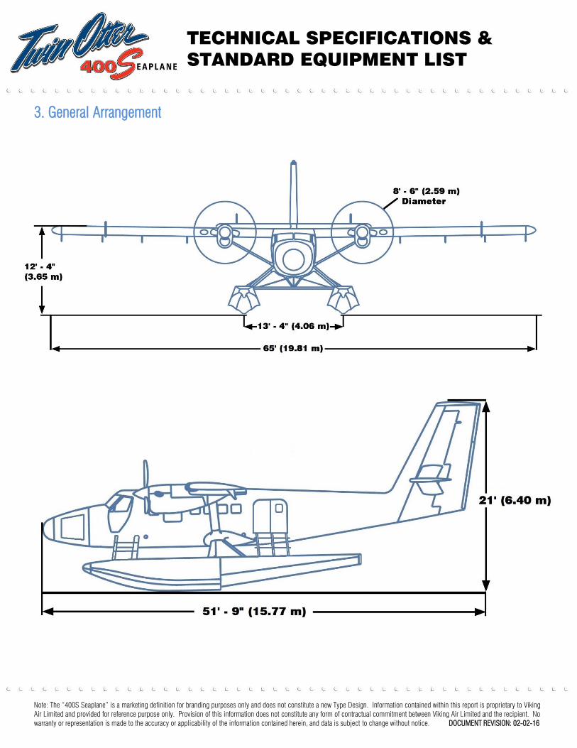
Cockpit Layout
All cockpit controls, switches, and displays are readily accessible
to the pilot for single pilot operation. There is a single overhead
panel located directly above the left pilot windshield that contains
controls for engine starting, ignition, DC electrical, and landing
lights. Circuit breaker panels are located on the left wall of the
flight compartment and at the base of the instrument panel
pedestal. All aircraft system controls and switches are located on
two sub-panels, directly below the two primary flight displays.
Instrument Panel Description
The left display unit (DU) is the pilot’s primary flight display
(PFD). The situational awareness and multi-function displays
(MFD) are located in the center. The right DU is the co-pilot’s
PFD. These display panels are installed in a single-piece, shock
mounted instrument panel.
To the right of the pilot’s PFD is the Electronic Standby Instrument
System (ESIS), the main function of which is to display altitude,
attitude, heading, and airspeed in the event of a total failure of the
primary avionics system or a total electrical failure. The ESIS is
powered by a dedicated battery that is entirely independent of the
main DC electrical system.
A chronometer is located inboard of the co-pilot’s PFD. The clock
occupies a 3 ATI standard space.
The PFD control panels are directly inboard of each PFD. The
flight guidance control panel is directly above the multifunction
display.
Fuel system controls and switches are located directly below the
ESIS on the left side of the instrument panel. Engine fire control
switches are mounted outboard of the flight guidance control
panel.
The MFD controller, the display reversion control panel, and
dimming control for the instrument panel are located on the aft
face of the center control yoke.
TECHNICAL SPECIFICATIONS &
STANDARD EQUIPMENT LIST
Note: The “400S Seaplane” is a marketing definition for branding purposes only and does not constitute a new Type Design. Information contained within this report is proprietary to Viking
Air Limited and provided for reference purpose only. Provision of this information does not constitute any form of contractual commitment between Viking Air Limited and the recipient. No
warranty or representation is made to the accuracy or applicability of the information contained herein, and data is subject to change without notice. DOCUMENT REVISION: 02-02-16
The lower sub-panel on the left side contains all switches for
internal and external lighting. The lower right sub-panel contains
switches for certain emergency and configuration functions.
Engine fire detection indication and control switches are mounted
outboard of the flight guidance control panel, at the top center of
the instrument panel. Dimming controls for instrument panel
lighting are mounted forward of the multifunction controller on
the control yoke.
Primary Flight Display
The Primary Flight Display (PFD) provides all the essential flight
data to the pilot. The PFD displays attitude, heading, airspeed and
altitude in the left 2/3 window.
Attitude information is displayed on the electronic Attitude
Direction Indicator (ADI) and heading and course information on
the electronic Horizontal Situation Indicator (HSI).
Situational Awareness & Systems Multifunction Display
(MFD)
The situational awareness formats (primarily mapping) with
various other system displays (primarily the flight plan) in
dedicated windows. The MFD display can also be used for the
aircraft systems displays, for control of the various components
of the avionics system, and for the display of CAS (Crew Alerting
System) messages.
Flight Management System (FMS)
The Flight Management System (FMS) provides flight planning
capability, navigation information and flight performance data to
the pilot. The FMS is capable of managing flight planning details
from aircraft take-off to touchdown including predictions of fuel
and time.
The FMS uses two navigation databases, which contain
worldwide or regional data, namely a custom database which
contains flight plans and pilot defined waypoints and an aircraft
database consisting of aircraft specific parameters used in FMS
performance calculations.
The FMS uses information from the databases stored in memory
and information from the GPS and ADAHRS to calculate and
display navigational and flight planning information.
Flight planning information can be entered by the pilot using the
MF Controller keyboard.
The FMS shows information on the PFD and upper MFD for:
Flight planning
Navigation
Situational awareness
Flight performance data
APEX Super-Lite Avionics System Functionality
The Apex system connects to and controls the following stand-
alone Honeywell equipment:
Air Data Attitude Heading Reference System (ADAHRS)
Dual Multi-Mode Digital Radios (MMDR)
Single Global Positioning System (GPS)
Single Mode S Transponder
Dual magnetometers
Single DME
Single Radar Altimeter
ADAHRS
The aircraft is equipped with an Air Data and Attitude Heading
Reference System (ADAHRS). The system provides primary
attitude, heading and air data parameters to the Modular Avionics
Unit (MAU).
Multi-Mode Digital Radios
Two Multi-Mode Digital Radio (MMDR) integrated transceivers
are installed in the nose avionics bay comprising one transmitter
and six receivers. The single transmitter is a 2,280 channel, 16
Watt, double sideband amplitude modulation communication
transmitter capable of 8.33 or 25 kHz channel spacing operation.
Global Positioning System
A Global Positioning System (GPS) sensor is installed in the nose
avionics bay. The receiver uses 24 channels grouped in 3
hardware groups each consisting of 8 channels. One group is
used for navigation at any given time. The GPS sensor unit
calculates and outputs navigation data, satellite measurement
data, Receiver Autonomous Integrity Monitoring (RAIM) and
Predictive RAIM (PRAIM).
Mode S Transponder
A Mode S transponder is installed behind the primary PFD
controller. The transponder provides Air Traffic Control Radar
Beacon System (ATCRBS), Mode-S.

TECHNICAL SPECIFICATIONS &
STANDARD EQUIPMENT LIST
Note: The “400S Seaplane” is a marketing definition for branding purposes only and does not constitute a new Type Design. Information contained within this report is proprietary to Viking
Air Limited and provided for reference purpose only. Provision of this information does not constitute any form of contractual commitment between Viking Air Limited and the recipient. No
warranty or representation is made to the accuracy or applicability of the information contained herein, and data is subject to change without notice. DOCUMENT REVISION: 02-02-16
Dual Magnetometers
Two magnetometers are mounted in the vertical stabilizer and
provide information to the ADAHRS in magnetic heading mode.
Single Distance Measuring Equipment (DME)
One DME transceiver is installed in the nose avionics bay. The
maximum range of the DME transceiver is 389 nautical miles.
Single Radar Altimeter
The radar altimeter system measures the aircraft height Above
Ground level (AGL). The digital readout for radio altitude is
displayed in white text in a black box in the lower center part of
the attitude display on the PFD. The radar altitude display is
removed at altitudes greater than 2,500 feet. When altitude is
less than 550 feet, the lower portion of the PFD altitude tape will
show a yellow cross hatched box to indicate ground proximity.
Additional Flight Deck Systems
Electronic Standby Instrument System (ESIS)
An Electronic Standby Instrument System (ESIS) is installed and
displays altitude, attitude, airspeed, and magnetic heading. The
ESIS is completely independent from the APEX Super-Lite
system.
Magnetic Standby Compass
An illuminated magnetic standby compass is mounted at the top
of the windshield center post.
Emergency Locator Transmitter (ELT)
An ELT is installed in the empennage connected to an antenna on
top of the fuselage just forward of the vertical stabilizer. It
transmits on the international distress frequencies of 121.5,
243.0 and 406 MHz.
Clock
An illuminated quartz chronometer is located on the instrument
panel, to the right of the upper multifunction display. A setting
knob is provided beside the clock face.
Intercom
An intercom for communication between the pilots is standard.
The intercom system is voice activated, and no transmit switch is
provided on the control wheel for the intercom.
13. Interior
A lightweight interior package is standard fitment to all aircraft.
This commuter interior complies with FAR 23.853 at amendment
23-49 flammability specifications.
Seating
Seventeen upholstered seats are fitted as standard in the cabin,
with provisions for under seat stowage of hand baggage.
The seating configuration can be adapted to 15 or 19 seat interior
configuration. Passenger seats can be removed and re-installed
when necessary for the transportation of cargo. The seats are
secured to the Douglas track that is attached to the floor rails and
cabin side rails, and optional coin matting can be installed to
protect the composite floor panels.
All passenger seats are equipped with lap type safety belts.
14. Cargo and Baggage Loading
The rear baggage compartment has a usable volume of 88 cubic
feet (2.5 m3
), and can carry up to 500 pounds (225 kg), of which
a maximum of 150 pounds (68 kg) may be loaded on the rear
baggage compartment aft shelf extension.
Baggage tie-down rings are provided for the baggage
compartment.
Cargo nets separate the rear baggage compartment from the
passenger cabin. The rear baggage compartment is accessed
through the main passenger access door for ease of loading.
Note: the 400S is not equipped with a separate rear cargo door.
15. Exterior Finishing
The basic aircraft specification is unpainted allowing for a range
of optional exterior paint schemes to be added upon request.
TECHNICAL SPECIFICATIONS &
STANDARD EQUIPMENT LIST
Note: The “400S Seaplane” is a marketing definition for branding purposes only and does not constitute a new Type Design. Information contained within this report is proprietary to Viking
Air Limited and provided for reference purpose only. Provision of this information does not constitute any form of contractual commitment between Viking Air Limited and the recipient. No
warranty or representation is made to the accuracy or applicability of the information contained herein, and data is subject to change without notice. DOCUMENT REVISION: 02-02-16
16. Additional Loose Equipment
LCD Screen Cleaner & Microfiber Cloth
Fuel Dipstick Gauge
Gust Lock
Cowl Plugs (2)
Electronic Noise Cancelling Headsets (2)
Propeller Restraining Device (2)
Engine Exhaust Cover (4)
Pitot Tube Cover (2)
Keys for Aircraft Doors (8)
External Tie Down Rings (3)
Equipment Bag
Maintenance Laptop and Computer Case
17. Emergency Equipment
First Aid Kit
A first aid kit is located on the aft side of the forward cabin wall.
Portable Fire Extinguishers
A handheld fire extinguisher is located on the aisle floor beside
Co-pilot's seat in the flight compartment. A secondary handheld
fire extinguisher is located in the cabin, forward of the main
passenger access door.
Emergency Exits
Two plug-type emergency exits are provided in the passenger
cabin, one on each side of the cabin at the forward end. Each is
secured in the closed position by two plates on the lower edge of
the door and by the hatch release mechanism on the upper edge
of the door; each is jettisoned by detaching the cover over the
release mechanism, pulling down the release handle (which then
becomes detached), and then pushing the door outward.
18. Documentation & Technical Publications
Viking Publications:
Canadian Technical Log Books (hard copy)
Pilot Operating Handbook (hard copy & digital subscription)
Emergency & Abnormal Procedures Quick Reference Handbook
(hard copy)
Aircraft Maintenance Manual (digital subscription)
Wiring Diagrams Manual (digital subscription)
Electrical Load Analysis (hard copy in acceptance binder)
Ground Handling Manual (digital subscription)
Structural Repairs Manual (digital subscription)
Illustrated Parts Catalogue (digital subscription)
DHC-6 Corrosion Prevention & Control Program (digital
subscription)
Inspection Requirements Manual (IR & IC) (digital subscription)
Structural Components Service Life Limits (digital subscription)
Avionics Airworthiness Limitations Manual (digital subscription)
Master Minimum Equipment List (TCCA website)
Pratt & Whitney PT6A-27 Publications:
Engine Technical Log Book (hard copy)
Engine Specific Operating Instructions (in POH)
Engine Maintenance Manual (digital subscription)
Engine Illustrated Parts Catalogue (digital subscription)
Engine Service Bulletins and Information Letters (web access)
Hartzell Propeller Publications:
Propeller Owner’s Manual (hard copy)
Propeller Service Bulletins & Information Letters (web access)
Honeywell Avionics Publications:
Pilot Operating Guide
Installation Manual (digital subscription)
Illustrated Parts Catalogue (digital subscription)
Service Bulletins, Info Letters & Subscriptions (web access)
Manuals for any applicable STCs:
Supplementary Maintenance Manual
Supplementary Flight Manual
Supplementary Parts Catalog
In addition, one (1) year digital subscriptions are provided by
Aircraft Technical Publishers (ATP) as well as AVTRAK. ATP
provides an on-line resource/portal to the technical
publications.
TECHNICAL SPECIFICATIONS &
STANDARD EQUIPMENT LIST
Note: The “400S Seaplane” is a marketing definition for branding purposes only and does not constitute a new Type Design. Information contained within this report is proprietary to Viking
Air Limited and provided for reference purpose only. Provision of this information does not constitute any form of contractual commitment between Viking Air Limited and the recipient. No
warranty or representation is made to the accuracy or applicability of the information contained herein, and data is subject to change without notice. DOCUMENT REVISION: 02-02-16
19. Aircraft Limited Warranty
400S Factory Warranty
For new aircraft, Viking provides a 12 month or 500 flight hour,
(whichever occurs first) limited warranty policy which covers
non-conformance to technical specifications for the aircraft and
any defects in material and/or workmanship under normal use
and service. Viking’s warranty policy is administered through
Viking’s Global Customer Support group. Individual (third party)
component warranties are transferred to the customer upon
delivery.
P&WC PT6A-27 Engine Warranty
Pratt & Whitney Canada’s (P&WC) standard warranty is 1000
flight hours from date of delivery.
Honeywell Avionics Warranty
Honeywell’s standard warranty policy is 3 years. Additional
warranty periods are available for an additional cost. Services are
provided via Honeywell’s Global Customer Support Center.
Hartzell Propeller Warranty
Hartzell Propeller’s standard warranty covers one year or 1,000
flight hours upon installation on the aircraft (whichever occurs
first).
20. Optional Equipment
Avionics Upgrade Package
The 400S can be equipped with a Honeywell Apex®
“Super-Lite”
optimized integrated avionics suite, per the standard
configuration with the addition of the following:
Weather radar (WX)
Class A Terrain Awareness and Warning System (TAWS)
2
nd
GPS
A second independent Global Positioning System (GPS) sensor
can be installed in the nose avionics bay. The sensor is as
described in Section 12 above.
2nd
Distance Measuring Equipment (DME)
A second DME transceiver can be installed in the nose avionics
bay. The transceiver is as described in Section 12 above.
Cockpit Voice Recorder (CVR)
A four channel Honeywell AR 120 cockpit voice recorder with
120-minute recording capacity can be fitted. The CVR is
integrated with the Apex system and captures radio
communication, intercom communication, and input from a flight
compartment area microphone that is mounted in the center of
the flight compartment, directly below the glare shield. The CVR
uses flash memory modules to record data, and has no moving
parts. It is equipped with an underwater location beacon.
Flight Data Recorder (FDR)
A Honeywell 246 words per second flight data recorder with 25
hour recording capacity can be fitted. The FDR uses flash memory
modules to record data, and has no moving parts. It is equipped
with an underwater location beacon.
TCAS I or II Traffic Advisory System
An optional TCAS display can be integrated into the Apex system,
and TCAS alerts are voiced through the aural warning system. The
system uses a processor, two directional antennas (upper and
lower) and a configuration module. Aural alerts are provided
through the audio panel and from there onward to the crew
headsets. TCAS II provides traffic advisories (TA), and resolution
advisories (RA) whereas TCAS I provides TA but not RA.
Customer Paint Scheme
A variety of customer paint options can be offered on request.
19 Seat and 15 Seat Interiors
The aircraft can be fitted with an optional 19 seat interior.
An optional 15 seat interior is available to provide additional
cargo carrying capacity on the rear RHS of the cabin by removing
the 6th row of double seats and connecting a cargo net to
removable stanchions. This allows flexible quick change
capability to 17 seats. A removable partition behind the 5th
row
of seating blocks passenger view and ensures safe stowage.
VHF Marine Radio
A VHF-FM transceiver is available for communication with marine
vessels or land based stations.
TECHNICAL SPECIFICATIONS &
STANDARD EQUIPMENT LIST
Note: The “400S Seaplane” is a marketing definition for branding purposes only and does not constitute a new Type Design. Information contained within this report is proprietary to Viking
Air Limited and provided for reference purpose only. Provision of this information does not constitute any form of contractual commitment between Viking Air Limited and the recipient. No
warranty or representation is made to the accuracy or applicability of the information contained herein, and data is subject to change without notice. DOCUMENT REVISION: 02-02-16
Bleed Air Heating and Cooling System
An optional heating and cooling system utilizing bleed air from
the engines and ram air from a scoop intake in the fuselage
provides heated, ram, or mixed air to maintain temperatures in
the cabin and flight compartment.
Heated air is circulated through ducts beneath the flooring to
outlets at the base of the cabin walls and the flight compartment
floor. Two tubes deliver heated air to the windshield defrost
outlets. The same ducts circulate cooling ram air or a mixture of
heated air and ram air in the cabin and flight compartment.
Two additional tubes deliver unconditioned ram air to the air
gaspers located on each outboard side of the instrument panel.
Additional ducts deliver ram air to the cabin through individual
passenger air gaspers located in the cove molding ducts on each
side of the cabin upper walls.
Passenger Life Vest Provisions
This comprises the Installation of pouches affixed to the
underside of the cabin seats for housing life vests. Life vests are
not included.
Coin Mat Flooring
Heavy duty coin mat flooring can be installed to protect the
composite floor panels from exposure to salt and/or sand when
operating in a saline environment.


![STANDARD LIST OF MEDICAL EQUIPMENT & THEIR TS · HSMP Armenia Equipment & Furniture Component HPIU: HH equipment specifications[1].doc 16/03/2011 page 1 of 27 STANDARD LIST OF MEDICAL](https://static.fdocuments.in/doc/165x107/5c626cb009d3f293108b6db8/standard-list-of-medical-equipment-their-ts-hsmp-armenia-equipment-furniture.jpg)