Technical Service Training Global...
114
Technical Service Training Global Fundamentals Curriculum Training – TF1010014S Automatic Transmission Student Information FCS-13200-REF CG7970/S en 12/2001
Transcript of Technical Service Training Global...

Technical Service Training
Global FundamentalsCurriculum Training – TF1010014S
Automatic Transmission
Student Information
FCS-13200-REF CG7970/S en 12/2001

Copyright © 2001 Ford Motor Company

Introduction Preface
Service Training 1
Global fundamentals training overview
The goal of the Global Fundamentals Training is to provide students with a common knowledge base of the
theory and operation of automotive systems and components. The Global Fundamentals Training Curriculum
(FCS-13203-REF) consists of nine self-study books. A brief listing of the topics covered in each of the self-study
books appears below.
� Shop Practices (FCS-13202-REF) explains how to prepare for work and describes procedures for lifting
materials and vehicles, handling substances safely, and performing potentially hazardous activities (such as
welding). Understanding hazard labels, using protective equipment, the importance of environmental policy,
and using technical resources are also covered.
� Brake Systems (FCS-13201-REF) describes the function and operation of drum brakes, disc brakes, master
cylinder and brake lines, power-assist brakes, and anti-lock braking systems.
� Steering and Suspension Systems (FCS-13196-REF) describes the function and operation of the power-
assisted steering system, tires and wheels, the suspension system, and steering alignment.
� Climate Control (FCS-13198-REF) explains the theories behind climate control systems, such as heat transfer
and the relationship of temperature to pressure. The self-study also describes the function and operation of the
refrigeration systems, the air distribution system, the ventilation system, and the electrical control system.
� Electrical Systems (FCS-13197-REF) explains the theories related to electricity, including the characteristics
of electricity and basic circuits. The self-study also describes the function and operation of common
automotive electrical and electronic devices.
� Manual Transmission and Drivetrain (FCS-13199-REF) explains the theory and operation of gears.
The self-study also describes the function and operation of the drivetrain, the clutch, manual transmissions
and transaxles, the driveshaft, the rear axle and differential, the transfer case, and the 4x4 system.
� Automatic Transmissions (FCS-13200-REF) explains the function and operation of the transmission and
transaxle, the mechanical system, the hydraulic control system, the electronic control system, and the transaxle
final drive. The self-study also describes the theory behind automatic transmissions including mechanical
powerflow and electro-hydraulic operation.
� Engine Operation (FCS-13195-REF) explains the four-stroke process and the function and operation of the
engine block assembly and the valve train. Also described are the lubrication system, the intake air system,
the exhaust system, and the cooling system. Diesel engine function and operation are covered also.
� Engine Performance (FCS-13194-REF) explains the combustion process and the resulting emissions.
The self-study book also describes the function and operation of the powertrain control system, the fuel
injection system, the ignition system, emissions control devices, the forced induction systems, and diesel
engine fuel injection. Read Engine Operation before completing Engine Performance.
To order curriculum or individual self-study books, contact Helm Inc.
Toll Free: 1-800-782-4356 (8:00 am – 6:00 pm EST)
Mail: 14310 Hamilton Ave., Highland Park, MI 48203 USA
Internet: www.helminc.com (24 hours a day, 7 days a week)

Contents Introduction
2 Service Training
Introduction.................................................................................................................................. 1Preface ...................................................................................................................................................................... 1
Global fundamentals training overview .......................................................................................................... 1
Contents .................................................................................................................................................................... 2
Lesson 1 – Automatic transmissions ........................................................................................... 5General ..................................................................................................................................................................... 5
Objectives ........................................................................................................................................................ 5
At a glance ................................................................................................................................................................ 6Automatic transmissions ................................................................................................................................. 6
Theory ....................................................................................................................................................................... 7Torque converter .............................................................................................................................................. 7Gear train ......................................................................................................................................................... 8
Powerflow ................................................................................................................................................................. 9Basic powerflow .............................................................................................................................................. 9
Lesson 2 – Torque converter ..................................................................................................... 10General ................................................................................................................................................................... 10
Objectives ...................................................................................................................................................... 10
At a glance .............................................................................................................................................................. 11Torque converter overview ............................................................................................................................ 11
Components............................................................................................................................................................ 12Three-element converter ............................................................................................................................... 12
Operation................................................................................................................................................................ 16Fluid flow reversal ......................................................................................................................................... 16Torque multiplication .................................................................................................................................... 16
Lock-up ................................................................................................................................................................... 19Hydraulic and mechanical coupling .............................................................................................................. 19Centrifugal clutch .......................................................................................................................................... 20Hydraulically applied torque converter clutch .............................................................................................. 22
Lesson 3 – Hydraulic principles ............................................................................................... 25General ................................................................................................................................................................... 25
Objectives ...................................................................................................................................................... 25
At a glance .............................................................................................................................................................. 26Hydraulics overview...................................................................................................................................... 26
Oil pump ................................................................................................................................................................. 28Oil pump purpose .......................................................................................................................................... 28Typical pump operation ................................................................................................................................. 30Pressure regulation ........................................................................................................................................ 31
Fluid ........................................................................................................................................................................ 35Fluid flow ...................................................................................................................................................... 35Flow control .................................................................................................................................................. 36Valve body ..................................................................................................................................................... 41Fluid circuit diagrams ................................................................................................................................... 42
Control valves ........................................................................................................................................................ 44Governor valve .............................................................................................................................................. 44Throttle valve circuit ..................................................................................................................................... 45Vacuum modulator ........................................................................................................................................ 46Throttle valve ................................................................................................................................................ 48

Introduction Contents
Service Training 3
Lesson 4 – Apply devices ........................................................................................................... 50General ................................................................................................................................................................... 50
Objectives ...................................................................................................................................................... 50
At a glance .............................................................................................................................................................. 51Clutches and bands ........................................................................................................................................ 51
Clutches .................................................................................................................................................................. 52Multiple-disc clutch ...................................................................................................................................... 52
Bands ...................................................................................................................................................................... 60Bands and servos ........................................................................................................................................... 60
Accumulators and modulators ............................................................................................................................. 62Purpose of accumulators and modulators ..................................................................................................... 62
Lesson 5 – Planetary gear sets .................................................................................................. 63General ................................................................................................................................................................... 63
Objectives ...................................................................................................................................................... 63
At a glance .............................................................................................................................................................. 64Purpose of a planetary gear set ..................................................................................................................... 64
Operation................................................................................................................................................................ 65Reduction ...................................................................................................................................................... 65Direct drive .................................................................................................................................................... 66Reverse .......................................................................................................................................................... 67
Types ....................................................................................................................................................................... 68Simple and compound gear trains ................................................................................................................. 68
Simpson gear train ................................................................................................................................................ 69Powerflow ..................................................................................................................................................... 69
Operation................................................................................................................................................................ 78Advantages of planetary gear sets ................................................................................................................. 78Compound gear train ..................................................................................................................................... 79
Lesson 6 – Transaxle .................................................................................................................. 80General ................................................................................................................................................................... 80
Objectives ...................................................................................................................................................... 80
At a glance .............................................................................................................................................................. 81Transaxle theory ............................................................................................................................................ 81
Systems ................................................................................................................................................................... 83Chain drive system ........................................................................................................................................ 83
Final drive .............................................................................................................................................................. 84Purpose .......................................................................................................................................................... 84
Components............................................................................................................................................................ 85Idler gear type ............................................................................................................................................... 85Chain drive type ............................................................................................................................................ 87
Differential assembly ............................................................................................................................................. 88Operation – wheels straight ........................................................................................................................... 88Operation – wheels turned ............................................................................................................................ 89

Contents Introduction
4 Service Training
Lesson 7 – Electronic controls .................................................................................................. 91General ................................................................................................................................................................... 91
Objectives ...................................................................................................................................................... 91
At a glance .............................................................................................................................................................. 92Control systems ............................................................................................................................................. 92
System inputs ......................................................................................................................................................... 93Control module theory .................................................................................................................................. 93Control module inputs ................................................................................................................................... 94
System outputs ..................................................................................................................................................... 100Control system outputs ................................................................................................................................ 100Solenoid operations ..................................................................................................................................... 104
Lesson 8 – Diagnosis ................................................................................................................ 108General ................................................................................................................................................................. 108
Objective ..................................................................................................................................................... 108
At a glance ............................................................................................................................................................ 109Symptom-to-system-to-component-to-cause diagnostic process ............................................................... 109Workshop literature ..................................................................................................................................... 109
List of abbreviations ................................................................................................................ 110
Service Training 5
Lesson 1 – Automatic transmissions General
Objectives
Upon completion of this lesson, you will be able to:
� Identify the primary purpose of the transmission.
� Describe the functions of the three major transmission systems: torque converter, gear train, and hydraulic
control system.
� Describe powerflow through the transmission.

6 Service Training
At a glance Lesson 1 – Automatic transmissions
Automatic transmissions
The purpose of a transmission is to modify the
engine’s rotational force, or torque, and transfer it to
the vehicle’s drive axle. Through its torque converter
and gear sets, the transmission provides the necessary
force to move the vehicle. The transmission also
allows the vehicle to be operated in reverse. This
section introduces the basic operating principles of
automatic transmissions.
Automatic transmissions have many design
variations. However, they are all similar in that they
use three basic systems:
� Torque converter
� Gear train
� Hydraulic control system

Service Training 7
Lesson 1 – Automatic transmissions Theory
Torque converter
ATX002-A/VF
1
3
2
1 Engine crankshaft
2 Flex plate
3 Torque converter
The torque converter provides a fluid coupling that
links the engine to the transmission gear train.
(In a fluid coupling, the spinning motion of the
transmission fluid transfers rotational force from the
crankshaft to the transmission.) At low speeds, the
torque converter multiplies the engine torque when
operating as a fluid coupling. When equipped with a
torque converter clutch, the converter also provides
direct mechanical (lock-up) drive under certain
operating conditions.

8 Service Training
Theory Lesson 1 – Automatic transmissions
Gear train
Typical simple gear set
1 Ring gear
2 Sun gear
Hydraulic control system
� The hydraulic control system controls the clutches
and bands needed to provide gear ratios and shift
from one gear to another.
� This system also distributes oil to the torque
converter and the transmission’s lubrication and
cooling systems.
� The hydraulic control system consists of a sump
(oil pan), oil pump, valves to regulate pressure and
redirect flow, and pistons to actuate the friction
clutches or bands.
3 Planet carrier
4 Planet gears (pinions)
� A typical gear train includes the input shaft;
planetary gear set, and output shaft.
� Two different types of gear trains are used. A
simple, or “Simpson,” gear train and a compound
or “Ravigneaux” gear train.
� A planetary gear set has three members: the ring
gear, the sun gear, and the pinion (or “planet”)
gears.
� These members are driven or held by friction
(hydraulic) clutches, one-way (mechanical)
clutches, and brake bands.
� The gear train provides the reduction gear ratios,
as well as direct drive, overdrive, and reverse.
ATX003-C/VF
1
2
3
4

Service Training 9
Lesson 1 – Automatic transmissions Powerflow
ATX004-A/VF
8
910
765
2 34
1
Basic powerflow
Typical powerflow
1 Engine crankshaft
2 Transmission turbine
3 Torque converter impeller
4 Oil pump
5 Input shaft
6 Friction clutch hub or drum
7 Planetary gear set
8 Output shaft
9 Valve body
10 Sump
� Power flows from the engine crankshaft through
the torque converter, which turns the transmission
input shaft. The planetary gear set transfers power
from the input shaft to the output shaft.
� The torque converter impeller, which is attached to
the engine, spins at engine speed and drives the oil
pump.
� The oil pump draws automatic transmission fluid
from the sump and sends pressurized oil to the
valve body and torque converter.
� The pressurized fluid inside the converter forms a
fluid coupling, which turns the transmission
turbine and input shaft.
� The input shaft is connected to a friction clutch
hub or drum.
� The clutch drum transfers power to the planetary
gear set. A gear set member can be coupled to
(driven by) the input shaft through a friction
clutch. In some cases, a gear set member is held to
the case by a friction clutch, one-way clutch, or
band.
� The output member of the planetary gear set
transfers engine power to the output shaft.

10 Service Training
General Lesson 2 – Torque converter
Objectives
Upon completion of this lesson, you will be able to:
� Identify the major components in a torque converter and explain their functions.
� Describe how the impeller and turbine provide a fluid coupling between the engine and transmission.
� Describe the operation of the stator and its one-way clutch.
� Explain how the stator, impeller, and turbine multiply torque.
� Describe the purpose of a lock-up converter.
� Explain how a centrifugal converter clutch provides a direct mechanical link between the engine and
transmission.
� Explain how a hydraulically applied piston clutch provides a direct mechanical link between the engine and
transmission.
Service Training 11
Lesson 2 – Torque converter At a glance
Torque converter overview
The rotational force, or torque, of the engine is
transferred to the automatic transmission through the
torque converter. This section describes how the
torque converter assembly components provide a fluid
coupling, multiply torque at low speeds, and establish
a direct mechanical link to the engine at high speeds.
The torque converter provides a fluid coupling
between the engine crankshaft and the transmission.
A flex plate is bolted to the rear of the crankshaft, and
the torque converter is bolted to the flex plate.
The automatic transmission fluid (ATF) in the torque
converter transfers the spinning motion of the
crankshaft to the transmission input shaft. Whenever
the engine is running, the torque converter is
spinning.
A simple torque converter has three basic elements:
an impeller, a stator and a turbine. Most modern
torque converters also have a clutch to lock the torque
converter at the proper vehicle operating conditions.

12 Service Training
Components Lesson 2 – Torque converter
Three-element converter
With the engine running and the torque converter
empty of fluid, the input shaft will not turn. However,
when the torque converter is filled with fluid, the
shaft will not only turn, it will turn with enough force
to drive the transmission internal components, which
drive the vehicle. Therefore, the fluid in the torque
converter makes the connection between the engine
and the transmission.
Based on the simple three-element converter, there is
no mechanical connection between the engine-driven
portion of the converter and the transmission input
shaft. Only the fluid in the torque converter couples
the engine to the input shaft. The paragraphs on the
following pages describe each component of the
torque converter and explain how the hydraulic
coupling is accomplished.
ATX006-A/VF
2
13
Basic torque converter
1 Fluid
2 Turbine
3 Impeller

Service Training 13
Lesson 2 – Torque converter Components
Impeller
If you are familiar with the design of vehicle water
pumps, then you already know what an impeller is.
The impeller on a water pump is a round component
with vanes that turns on a shaft. When the engine is
running, the spinning impeller vanes force coolant to
circulate through the coolant passages and radiator.
The impeller vanes on a torque converter work in a
similar way. The spinning impeller forces hydraulic
fluid to circulate via centrifugal force. The fluid is
carried in a circular motion by the vanes, and, as
speed increases, the fluid flows away from the center
of the impeller.
As the fluid flows outward, the vanes carry it toward
the upper edge of the impeller. As impeller speed
increases, the fluid gains enough momentum to flow
off the edges of the vanes and out of the impeller. The
fluid comes out of the impeller with enough force to
drive the transmission input shaft if the force is
properly directed.
Impeller operation
1 Impeller shaft
2 Impeller vane
3 Spinning impeller
4 Coolant thrown outward by centrifugal force
ATX007-B/VF
43
21

14 Service Training
Components Lesson 2 – Torque converter
Three-element converter (continued)
Turbine
Torque converter exploded view
1 Turbine
2 Stator
3 Impeller
4 Turbine blades
5 Stator one-way clutch
The turbine in a torque converter is similar in
construction to the impeller. That is, the turbine is a
round part with vanes, or blades. This construction
makes sense when you consider that the turbine
catches the fluid thrown off by the impeller.
As the fluid is thrown off the impeller, the blades on
the turbine capture it, forcing the fluid to the center of
the turbine. This force turns the turbine before the
fluid flows back through the center of the turbine to
the impeller.
ATX009-A/VF
3
12
45
The force of the fluid striking the turbine blades is
related to engine speed. The faster the crankshaft
rotates, the more force the fluid transfers from the
impeller to the turbine. When the engine is idling, the
fluid does not have enough force to turn the turbine
against the holding ability of the brakes. The fluid is
merely circulated from the impeller to the turbine,
and back again.
The fluid leaves the impeller in a clockwise direction
and returns from the turbine in a counterclockwise
direction.

Service Training 15
Lesson 2 – Torque converter Components
Stator (reactor)
The stator, or reactor, is positioned between the
turbine and impeller. The purpose of the stator is to
change the direction of fluid flow as it moves from
the center of the turbine to the center of the impeller.
The fluid flows from the impeller to the turbine in a
clockwise direction. However, as the fluid flows
through the turbine, its direction is reversed to a
counterclockwise direction.
If the fluid were allowed to return to the impeller in a
counterclockwise direction, it would enter the
impeller as an opposing fluid flow, which would
reduce the pumping efficiency of the impeller. The
impeller would have to spend part of the rotational
force, or torque, it receives from the engine to redirect
the fluid flow.
When the stator redirects the fluid to enter the
impeller in a clockwise direction, no torque is wasted.
In fact, the redirected fluid actually helps push the
impeller, thus multiplying torque.
The stator consists of several blades attached to a hub
which is mounted on a one-way clutch.
The clutch assembly has an inner and outer race, or
ring, with the two races separated by spring-loaded
rollers. The inner race is mounted on a splined, or
grooved, stator support, which extends from the
transmission into the torque converter. Because the
inner race is splined to the stator support, it is fixed
and cannot turn.
The outer race is placed over the inner race. The inner
and outer race are separated by spring-loaded rollers.
The rollers are positioned against the low end of
ramps machined into the outer race. When the springs
are installed, the rollers are held against the ramps.
The rollers, ramps, and races allow the outer race to
turn in only one direction. When the stator turns
clockwise, each roller moves down the ramp against
the spring, allowing the stator to turn. If the stator is
rotated in the opposite direction, the spring pushes
each roller up the ramp, where it becomes wedged
between the two races. With the rollers wedged, the
stator is locked to the inner race and cannot rotate.
16 Service Training
Operation Lesson 2 – Torque converter
Fluid flow reversal
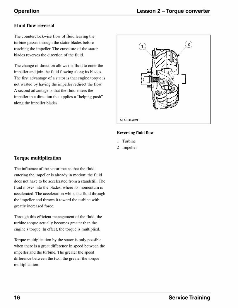
The counterclockwise flow of fluid leaving the
turbine passes through the stator blades before
reaching the impeller. The curvature of the stator
blades reverses the direction of the fluid.
The change of direction allows the fluid to enter the
impeller and join the fluid flowing along its blades.
The first advantage of a stator is that engine torque is
not wasted by having the impeller redirect the flow.
A second advantage is that the fluid enters the
impeller in a direction that applies a “helping push”
along the impeller blades.
ATX008-A/VF
21
Reversing fluid flow
1 Turbine
2 Impeller
Torque multiplication
The influence of the stator means that the fluid
entering the impeller is already in motion; the fluid
does not have to be accelerated from a standstill. The
fluid moves into the blades, where its momentum is
accelerated. The acceleration whips the fluid through
the impeller and throws it toward the turbine with
greatly increased force.
Through this efficient management of the fluid, the
turbine torque actually becomes greater than the
engine’s torque. In effect, the torque is multiplied.
Torque multiplication by the stator is only possible
when there is a great difference in speed between the
impeller and the turbine. The greater the speed
difference between the two, the greater the torque
multiplication.

Service Training 17
Lesson 2 – Torque converter Operation
Torque multiplication
ATX010-A/VF
43
21
5
Stator one-way clutch operation
1 Turbine
2 Impeller
3 Rollers wedged between ramp and inner race
(clutch lock-up)
4 Direction of force on stator
5 Vortex flow
The stator’s one-way clutch plays an important role in
multiplying torque. The fluid circulating between the
impeller and the turbine is called vortex flow. This
flow exists only when there is a difference in
rotational speed between the impeller and turbine.
The greatest speed difference between these two
components occurs when a vehicle first accelerates
from a stop. At this point, the impeller is spinning, but
the turbine is not. Because of the great difference in
speed, vortex flow and torque multiplication are at
maximum. The vortex flow passing through the stator
blades tries to turn the stator counterclockwise. When
this happens, the clutch rollers move down the ramps
and lock the stator to its support.
As the vehicle accelerates, the turbine gradually gains
speed in relation to the impeller. Eventually, the
turbine speeds up to the point where the fluid begins
to flow in one direction (clockwise).
As centrifugal force reduces vortex flow, torque
multiplication is also reduced. Finally, when the
turbine’s speed reaches about 90 percent of the
impeller’s speed, the torque converter reaches
“coupling” phase. In this phase, the torque converter
simply transmits engine torque through the fluid
coupling to the transmission input shaft.
Coupling does not necessarily occur at a specific road
speed. For example, a vehicle may be moving at a
steady speed with the torque converter coupled to the
transmission. If the driver suddenly accelerates to
pass another vehicle, the higher engine rotation
increases the speed of the impeller, causing it to turn
faster than the turbine. With a significant speed
difference between the impeller and the turbine,
torque multiplication (and vortex flow) again occurs,
until the turbine “catches up” with the speed of the
impeller.

18 Service Training
Operation Lesson 2 – Torque converter
Torque multiplication (continued)
Stator one-way clutch operation
1 Turbine
2 Impeller
ATX011-A/VF
14
32
3 Rollers moved away from ramp (clutch unlocked)
4 Clockwise direction of force on stator
As turbine speed increases and vortex flow decreases,
the rotational force acting on the stator is reversed.
The clutch rollers move away from their ramps,
unlocking the clutch and allowing the stator to turn
freely (clockwise). The direction of the fluid striking
the stator blades also changes. Instead of flowing
against the front of the stator blades, the fluid strikes
the rear of the blades. If the clutch did not release the
stator, its blades would generate turbulence in the
flow, which would greatly reduce the torque
converter’s efficiency.
Service Training 19
Lesson 2 – Torque converter Lock-up
Hydraulic and mechanical coupling
Because the torque converter lacks a direct
mechanical link to the engine, it loses some engine
torque to fluid slippage. The speeds and loads
imposed on the fluid cause the impeller and turbine
blades to shear, or slip, through the fluid to a certain
degree.
This fluid slippage causes some inefficiency,
especially at higher vehicle speeds. The engine can
run faster than the turbine or output shaft, thus
wasting fuel. To eliminate this inefficiency, many
torque converters provide a direct mechanical link
(called lock-up) between the engine and transmission.
At lock-up, the turbine and impeller turn at exactly
the same speed. There is no fluid slippage, which
helps to reduce heat build-up.
A lock-up converter is one of the most common ways
of providing this mechanical link. A lock-up converter
mechanically links the turbine to the converter cover
at various operating speeds, depending on vehicle
model and driving conditions. The cover is
mechanically bolted to the engine. At lock-up, the
converter cover drives the turbine. The hydraulic link
is eliminated, and the engine and turbine are
mechanically locked together, directly driving the
transmission input shaft.
A lock-up converter requires a clutch to engage and
disengage the mechanical link between the engine and
the torque converter cover. Two major types of
converter clutches are the centrifugal clutch and the
hydraulically applied torque converter clutch.
The centrifugal type converter clutch was mainly used
before 1990. The hydraulically applied clutch is
mainly used in today’s vehicles.

20 Service Training
Lock-up Lesson 2 – Torque converter
Centrifugal clutch
Torque converter assembly
1 Cover
2 Torque converter clutch
3 Impeller assembly
4 Stator
5 Turbine
A centrifugal clutch is splined to the turbine by a
one-way clutch. As vehicle speed increases, the
hydraulically driven turbine and the lock-up clutch
splined to it turn with increasing speed. The
centrifugal force on the clutch shoes increases as the
clutch assembly turns faster and faster.
When the turbine and lock-up clutch are turning fast
enough, centrifugal force causes the clutch shoes to
move outward until they contact the inside surface of
the converter cover. The face of each shoe “grabs” the
cover and locks it to the turbine.
ATX005-B/VF
Service Training 21
Lesson 2 – Torque converter Lock-up
As vehicle speed drops, turbine speed and centrifugal
force are reduced. The return springs retract the clutch
shoes, the cover is released, and the turbine again
becomes hydraulically driven.
A one-way clutch drives the clutch assembly. With the
clutch engaged, the driver may release the accelerator
pedal slightly, allowing the vehicle to “coast.” This
allows the engine and input shaft to turn at different
speeds.
The friction shoes cannot release during coasting
because centrifugal force holds them against the
cover. Instead, the damper one-way clutch releases so
the input shaft can turn faster than engine speed.
When the driver accelerates, the damper one-way
clutch again locks the turbine to the clutch and
damper assembly.
The damper assembly one-way clutch ensures smooth
operation of the torque converter. The dampener
springs also contribute to smooth operation. These
springs absorb engine vibrations and cushion the
shoes as they engage the converter cover.
When torque demand during acceleration exceeds the
holding ability of the friction shoes, some slip occurs.
This slippage reduces torsional vibration during
higher engine load.

22 Service Training
Lock-up Lesson 2 – Torque converter
Hydraulically applied torque converter clutch
Converter clutch released
1 Rear chamber
2 TCC
3 Front chamber
4 Converter pressure
5 Clutch control valve
Another method of connecting the engine and
transmission directly is to use a torque converter
clutch (TCC) with torsional dampening springs
attached to the hub. The hub assembly is splined to
the input shaft or turbine assembly.
ATX012-A/VF
1 2
3
4
5

Service Training 23
Lesson 2 – Torque converter Lock-up
Hydraulic clutch released
Signals from the control module control the
application and release of the hydraulic converter
clutch. The control module applies and releases the
hydraulic clutch by turning the converter clutch
solenoid on or off. A solenoid is a type of electric
switch that includes a wire coil. When current is
applied, the coil is magnetized. The magnetic field
moves a rod that opens and closes a hydraulic
passage.
Hydraulic pressure is applied to the area between the
converter cover and the clutch piston plate. A
converter feed circuit in the valve body provides the
hydraulic pressure.
When the converter clutch solenoid is not activated by
the control module, the solenoid remains open. Line
pressure bleeds through the solenoid. The fluid is
routed through the converter front chamber, between
the TCC and the converter cover.
24 Service Training
Operation Lesson 2 – Torque converter
Hydraulically applied torque converter clutch (continued)
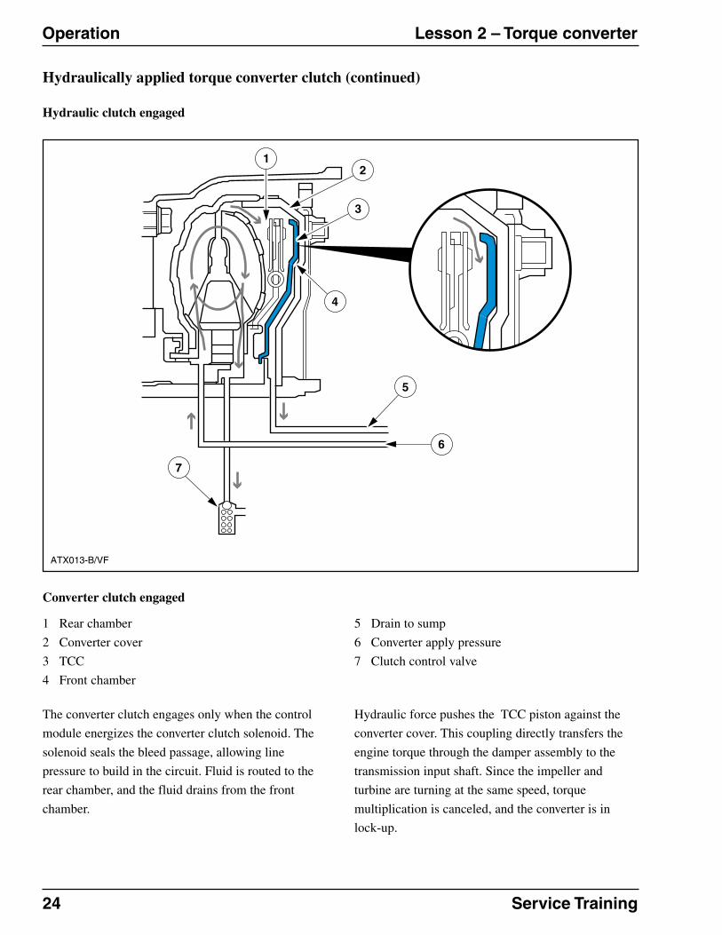
Hydraulic clutch engaged
Converter clutch engaged
1 Rear chamber
2 Converter cover
3 TCC
4 Front chamber
5 Drain to sump
6 Converter apply pressure
7 Clutch control valve
The converter clutch engages only when the control
module energizes the converter clutch solenoid. The
solenoid seals the bleed passage, allowing line
pressure to build in the circuit. Fluid is routed to the
rear chamber, and the fluid drains from the front
chamber.
Hydraulic force pushes the TCC piston against the
converter cover. This coupling directly transfers the
engine torque through the damper assembly to the
transmission input shaft. Since the impeller and
turbine are turning at the same speed, torque
multiplication is canceled, and the converter is in
lock-up.
ATX013-B/VF
7
5
6
3
21
4
Service Training 25
Lesson 3 – Hydraulic principles General
Objectives
Upon completion of this lesson, you will be able to:
� Identify the components in a transmission oil pump and describe how they provide fluid flow and pressure.
� Describe the three operating stages of the pump.
� Describe how the pressure regulator valve operates to maintain a desired system pressure.
� Describe how pressurized fluid transfers motion among moving parts.
� Describe a spool valve with multiple lands and explain how it opens and closes various hydraulic passages.
� Describe how the governor circuit operates to send road speed information to the hydraulic main control.
� Describe how the throttle valve (TV) can be connected to the engine to read throttle position or engine
performance.

26 Service Training
At a glance Lesson 3 – Hydraulic principles
Hydraulics overview
Hydraulics is the science that deals with the behavior
of fluids. In the automatic transmission, we are
specifically concerned with the behavior of fluid
under pressure. This section describes the basic
hydraulic principles at work in an automatic
transmission.
When pressurized liquid is properly controlled, it can
be used to transmit motion.
Fluid under pressure can be used to transfer motion
from one piston to another.
When the applying piston moves within the cylinder,
its motion is transmitted through the fluid to the
output piston, which moves the same distance as the
applying piston.
Of course, a mechanical link could be used to perform
this simple task, but using fluid has a very big
advantage: the two pistons do not have to be enclosed
in the same cylinder. In fact, they can be widely
separated in individual cylinders. All that is needed is
a connecting tube to confine the fluid as it moves
from cylinder to cylinder.
Single hydraulic cylinder
1 Applying piston
2 Fluid
3 Output piston
ATX014-A/VF
321
321

Service Training 27
Lesson 3 – Hydraulic principles At a glance
The applying piston transfers its motion through the
fluid to the output piston.
Compressing hydraulics
1 29,029 Kg (32 tons)
2 6.45 cubic centimeters (one cubic inch of water)
3 Compressed 10 percent
Apply and output cylinders
1 Applying piston
2 Fluid
3 Output piston
ATX015-A/VF
321
1 2 3
ATX016-A/VF
1
2
3
The ability of a fluid to transmit motion comes from
its incompressibility. That is, when a fluid is
squeezed, or compressed, its volume does not shrink.
So, for example, it would take 29,029 Kg (32 tons) to
compress 6.45 cubic centimeters (one cubic inch) of
water by 10 percent.

28 Service Training
Oil pump Lesson 3 – Hydraulic principles
Oil pump purpose
Because an automatic transmission requires
pressurized fluid, it must have a pressure source –
an oil pump. The oil pump is driven by the engine
and provides a source of fluid flow.
Types of pumps
Three styles of pumps are used in most automatic
transmissions:
� Rotary type
� Gear type
� Vane type
All pumps have an inlet and outlet port. The inlet port
is attached to the transmission oil filter, which is
submerged in the oil pan. Oil is pushed into the inlet
port by atmospheric pressure and by the low pressure
created by the rotating rotor, gear, or vane in the
pump. The outlet (or discharge) port leads to the
valve body.
Gear type pump
1 Driven gear
2 Crescent
3 Drive gear
4 Fluid squeezed out
5 Inlet (low pressure)
ATX017-B/VF
45
1 2
3

Service Training 29
Lesson 3 – Hydraulic principles Oil pump
Rotary type
A rotary type pump uses an inner rotor and an outer
rotor to create a low pressure. As fluid is drawn into
the pump, it is squeezed between the rotor lobes,
which carry the fluid around the pump housing to the
outlet port.
Gear type
A gear type pump uses a large gear with internal teeth
(called the driven gear) mounted over the drive gear
on the hub. This larger gear is off center, so the teeth
on the two gears only partially mesh. As the gears
turn, a progressively wider gap is formed between the
gear teeth. The gap creates a low pressure, which
sucks the fluid into the pump.
Because this gap must be filled with fluid, another
component, called the crescent, is added to the gear
assembly. The crescent prevents the fluid from
leaking back to the inlet port. As the gap between the
gear teeth narrows, the fluid is squeezed out between
the teeth and forced through the outlet port.
Vane type
A vane type pump uses centrifugal force to push fluid
through the pump. As the fluid enters the inlet port, it
is picked up by the rapidly spinning vanes.
Centrifugal force slings the fluid off the end of the
vanes and through the outlet port.

30 Service Training
Oil pump Lesson 3 – Hydraulic principles
Typical pump operation
The inlet of the transmission oil pump is connected to
a sump, or oil pan, in the bottom of the transmission
case. As the fluid is drawn up from the sump, it passes
through a filter, which removes particles and debris.
Fluid enters the pump inlet because air pressure
pushes down on the surface of the oil. At sea level, air
pressure is about 1.01 bar (14.7 psi). Air pressure
cannot actually push the fluid up through the strainer
into the pump. The pump first has to create a low
pressure, or void, at the inlet port opening. Then
atmospheric pressure can push the fluid into the pump
to fill the void.
In a gear type pump, the pump creates a low pressure
through the action of the gear teeth. The teeth are
tightly meshed, but as they rotate, they begin to
separate. This separation creates a low pressure
between the gear teeth, and atmospheric pressure
pushes the fluid in to fill this void.
Once in the pump, the fluid is trapped between the
gear teeth, which carry it around the pump housing
toward the outlet port. As the gear teeth approach the
outlet, the gap between the gear teeth begins to
narrow. The fluid cannot leak back toward the inlet
port because the crescent blocks its path.
The gap continues narrowing until the gear teeth
begin to mesh. At this point, the fluid is squeezed
between the teeth until it reaches the outlet port. From
the outlet, the fluid is discharged into the transmission
hydraulic system.
Gear pump operation
1 Crescent
2 Driven gear
3 Drive gear
4 Fluid squeezed out
5 Pump outlet
6 Oil sump filter
7 Sump (fluid pan)
8 Pump inlet
9 Low pressure
ATX018-A/VF
6
7 8
9
1 2
3
4
5

Service Training 31
Lesson 3 – Hydraulic principles Oil pump
Pressure regulation
Transmission oil pumps are classified as positive
displacement or variable displacement pumps.
A vane type pump is a variable displacement pump.
This means that it supplies a fixed quantity of oil
output once the engine reaches a specific speed.
“Feedback” pressure from the valve body return
circuit keeps the vane type pump from producing
more output than is required. This feature helps
conserve engine power by reducing the amount of
horsepower required to drive the pump.
Rotary and gear type pumps are positive displacement
pumps. This means that the pump must force out all
the fluid that enters it. There is no other escape for the
fluid except the outlet port. A positive displacement
pump continues to pump out fluid even if the pressure
on the outlet side is extremely high. In fact, if the
outlet port is blocked, a positive displacement pump
continues to operate until it eventually stalls from
extremely high pressure.
To prevent stall, a positive displacement pump must
have a method of rerouting the fluid flow if pressure
becomes too high. As pump pressure builds, a
pressure regulator valve opens and closes to maintain
system pressure at a safe level.
Movement of the pressure regulator valve is
controlled by a calibrated spring. The spring tension
determines the opening pressure of the regulator
valve.
Pressure regulator circuit
1 To system
2 Pressure regulator valve
3 Spring
4 Pump
5 Screen
6 Sump
ATX019 -A/VF
1
2
3
4
5
6

32 Service Training
Oil pump Lesson 3 – Hydraulic principles
Pressure regulation (continued)
Three stages of operation
The pressure regulator valve has three distinct stages
of operation:
� Filling the lines
� Converter supply
� Sump supply
Filling the lines
Immediately after the vehicle is started, the lines are
filled with fluid. At this stage, there is little resistance
to flow in the system, so pressure does not build up.
The spring below the regulator valve holds it in the up
(or closed) position.

Service Training 33
Lesson 3 – Hydraulic principles Oil pump
Converter supply
As pressure begins to rise in the system, the regulator
valve is forced down against the spring, and another
port is uncovered. Fluid from the pump flows through
this port into the torque converter circuit. Since the
torque converter is kept under constant pressure,
another fluid outlet is required to prevent excessive
pressure build-up.
Torque converter supply circuit
1 To torque converter
2 To system
3 Pressure regulator valve
4 Pump
5 Screen
6 Sump
ATX020-A/VF
12
3
4
5
6

34 Service Training
Oil pump Lesson 3 – Hydraulic principles
Pressure regulation (continued)
Sump supply
Pressure continues to build, and the regulator valve is
forced down further against the spring. Another oil
port is uncovered. This port connects to the sump in
the bottom of the transmission case. All excess oil is
returned to the sump, where it can be recirculated
through the pump inlet. This final stage is the normal
operating condition when the engine is running.
Balanced valve
Once the pressure regulator valve has reached stage 3,
the pressure in the main control system is regulated
by balancing the pressure against the force of the
valve spring. The spring controls the pressure, and the
valve adjusts itself automatically so that the spring
force acting upward is equal to the hydraulic pressure
acting downward.
If the pressure drops, the spring moves the valve up
and cuts off part of the flow to the sump (and to the
torque converter, if necessary) to maintain the
regulated pressure. This valve is called a balanced
valve, and the pressure it regulates is called control or
line pressure. Line pressure can also be controlled by
an electronic solenoid.
Sump supply circuit
1 Pressure regulator valve
2 Pump
3 Screen
4 Sump
ATX021 -A/VF
1
2
3
4

Service Training 35
Lesson 3 – Hydraulic principles Fluid
Fluid flow
In an automatic transmission, fluid is routed through
passages and bores. Although many of these are
located in the case and pump housing, most bores and
passages are in a master flow control device called the
valve body. Fluid flow through these passages is
controlled by either a single valve or a series of valves
working in combination.
With the exception of two valves, all the control
valves in the valve body operate automatically to
direct the fluid to perform certain functions. For
example, the shift from first to second gear, called the
1-2 shift, is a specific hydraulic function. When this
shift happens, the fluid flows through specific bores,
passages, and valves. This fluid flow is called an oil
circuit.
An automatic transmission has an oil circuit for each
hydraulic function. In fact, the pressure regulator
valve described in the previous section is an oil circuit
that controls pump pressure.
When you study an oil circuit, you are looking at a
schematic, or kind of map, that shows the fluid path
and valves for performing a specific function.

36 Service Training
Fluid Lesson 3 – Hydraulic principles
Flow control
ATX022-A/VF
543
1
6
78
2
Flow control circuit – valve closed
1 Pressure regulator valve
2 Valve bore
3 Valve closed
4 Piston at top of stroke
5 Cylinder
6 Exit port
7 Rod
8 Pump
To demonstrate basic principles of flow control, we
will examine a hypothetical valve bore. This bore is
connected to the fluid flow from the pressure
regulator valve.
Within this bore is a single-land valve connected to a
rod that extends through one end of the bore. (A land
is the round sealing surface of the valve.) On the sides
of the bore are two ports: an inlet port joined to the
fluid from the pressure regulator, and an exit port
joined to a passage leading to a cylinder. Within this
cylinder is a piston at the top of its stroke.
With the engine running, fluid flows from the
pressure regulator circuit to the valve bore and stops.
It cannot pass through the bore because the valve is
blocking the inlet port.

Service Training 37
Lesson 3 – Hydraulic principles Fluid
Flow control circuit – valve open
1 Pressure regulator valve
2 Valve open
3 Pressurized fluid in cylinder
4 Piston
5 Pump
If the valve is manually opened, fluid flows into the
inlet port, through the bore, and out the exit port on its
way to the cylinder.
When the fluid reaches the cylinder, it pushes on the
piston surface, forcing it to move the length of the
cylinder bore. The force generated by the pump is
transferred to the piston.
ATX023-B/VF
1
5
23 4

38 Service Training
Fluid Lesson 3 – Hydraulic principles
Flow control (continued)
Flow control circuit – fluid pushed back by spring
1 Pressure regulator valve
2 Valve closed
3 Exhaust port
4 Pump
The oil circuit is functional, but it lacks one important
feature: automatic reset. When the pressure is
released, the piston does not automatically return to
the top of the bore, ready for another stroke. To make
the piston reset automatically, a spring is added
behind the piston.
With the valve closed and the fluid flow stopped, the
spring tension should push the piston back to the top
of the cylinder. However, the spring cannot move the
piston as long as pressurized fluid is trapped in the
cylinder circuit. The spring cannot move the piston
until the fluid is drained from the cylinder.
To provide an outlet for draining the pressurized fluid,
the circuit must be reworked. Adding an exhaust
passage to the sump and offsetting the cylinder
passage allows the inlet port to be sealed without
trapping fluid in the cylinder.
Now the valve can open the inlet port from the pump,
as well as the exit port to the cylinder. At the same
time, the valve seals the exhaust port to the sump,
preventing any pressure loss.
When the valve closes the inlet port, it also opens the
cylinder passage to the exhaust port. The fluid drains
out of the exhaust port as the spring pushes the piston
back through the cylinder.
ATX025-B/VF
1
3
2
4

Service Training 39
Lesson 3 – Hydraulic principles Fluid
Spool valve
The spool valve has two or more lands, or sealing
areas, connected by a rod, giving the valve a spool
shape. The area between the lands allows fluid to flow
through the valve bore.
When a spool valve moves, the lands open and close
various ports to direct fluid flow. For example, the
upper land is at the top of the bore, opening the pump
inlet. The lower land seals the exhaust port, allowing
fluid to flow through the center of the cylinder bore.
Spool valve circuit
1 Pressure regulator valve
2 Spool valve
3 Valve land (sealing surface)
4 To cylinder
5 To sump
6 Pump
ATX026-B/VF
6
3 5
4
23
1
40 Service Training
Fluid Lesson 3 – Hydraulic principles
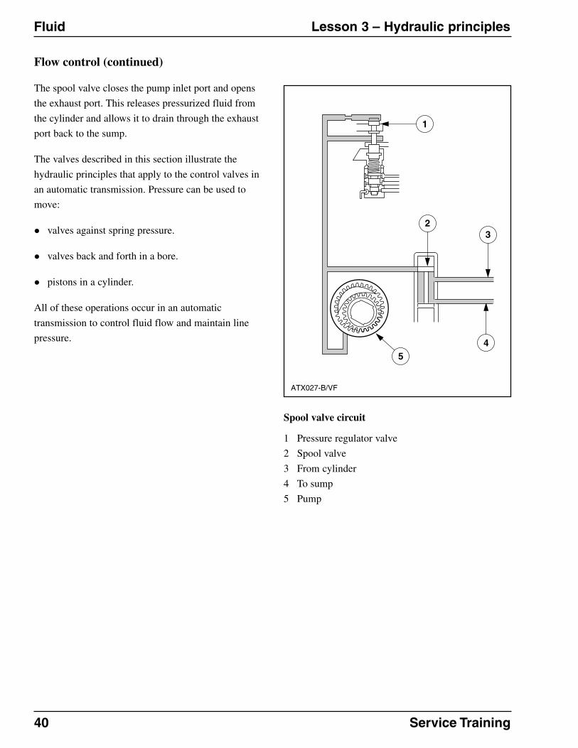
Flow control (continued)
The spool valve closes the pump inlet port and opens
the exhaust port. This releases pressurized fluid from
the cylinder and allows it to drain through the exhaust
port back to the sump.
The valves described in this section illustrate the
hydraulic principles that apply to the control valves in
an automatic transmission. Pressure can be used to
move:
� valves against spring pressure.
� valves back and forth in a bore.
� pistons in a cylinder.
All of these operations occur in an automatic
transmission to control fluid flow and maintain line
pressure.
Spool valve circuit
1 Pressure regulator valve
2 Spool valve
3 From cylinder
4 To sump
5 Pump
ATX027-B/VF
54
32
1
Service Training 41
Lesson 3 – Hydraulic principles Fluid
Valve body
ATX028-A/VF
1
2
3
4
5 6
7
8
9
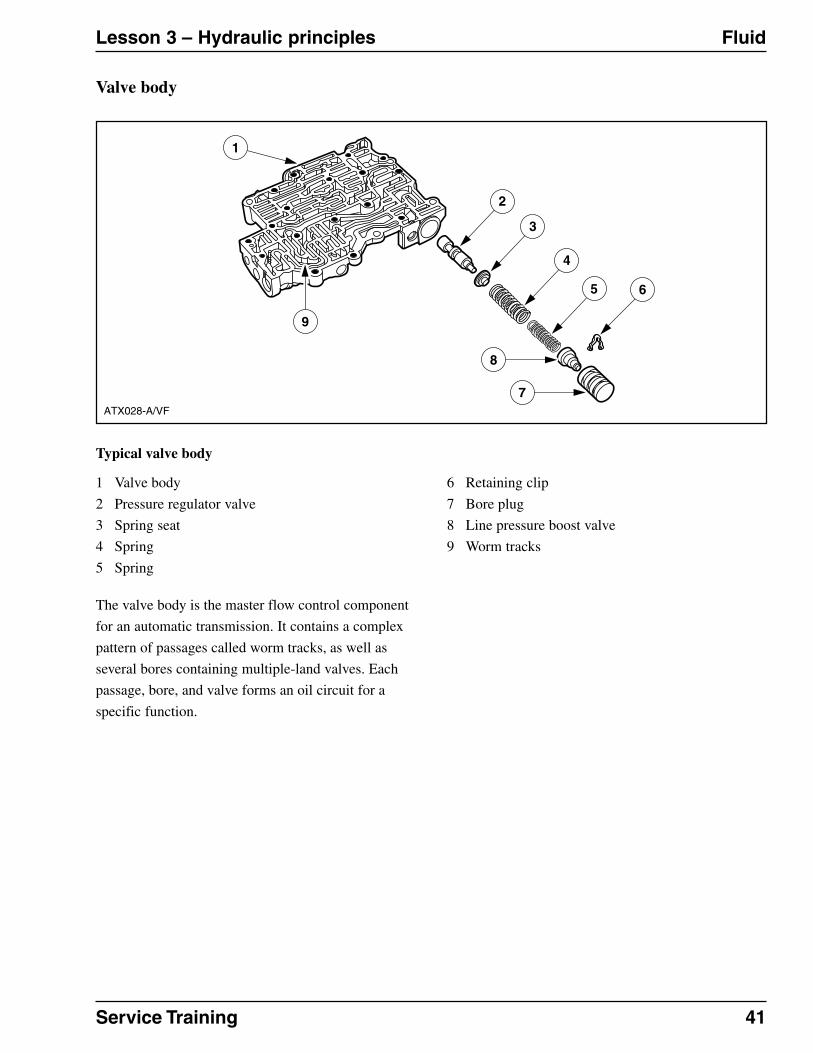
6 Retaining clip
7 Bore plug
8 Line pressure boost valve
9 Worm tracks
Typical valve body
1 Valve body
2 Pressure regulator valve
3 Spring seat
4 Spring
5 Spring
The valve body is the master flow control component
for an automatic transmission. It contains a complex
pattern of passages called worm tracks, as well as
several bores containing multiple-land valves. Each
passage, bore, and valve forms an oil circuit for a
specific function.

42 Service Training
Fluid Lesson 3 – Hydraulic principles
Fluid circuit diagrams
Using a flow diagram, you can trace an oil circuit and
determine exactly which valves and passages are used
to accomplish a specific transmission function.
Flow diagram – pressure regulator valve
1 Pressure regulator valve
2 Springs
3 Screen
4 Pump
ATX029-A/VF
1
2
4 3

Service Training 43
Lesson 3 – Hydraulic principles Fluid
Flow diagram – manual valve
1 Pressure regulator valve
2 Manual valve
3 Trapped fluid
4 Valve lands
If you follow the pump flow away from the pressure
regulator, you find the manual valve. This valve is
connected through a mechanical linkage to the shift
selector in the vehicle’s passenger compartment. The
manual valve moves in or out of its bore depending
on the position of the shift selector (for example:
“P,” “R,” or “D”).
The line pressure stops at the manual valve because it
is trapped between two lands. In other gear ranges,
the valve lands move to redirect the flow to various
valves, clutches, and servos.
ATX030-B/VF
3
4
2
1

44 Service Training
Control valves Lesson 3 – Hydraulic principles
Governor valve
ATX031-A/VF
2 3 45
87
6
10
1
9
6 Sleeve
7 Governor valve
8 Outer land
9 Valve spring
10 Secondary weight
When the driver moves the shift selector lever to one
of the drive positions, another important oil circuit
becomes active. The governor valve circuit is used to
time the shifts in an automatic transmission.
The governor valve takes the line pressure directed
from the manual valve and transforms it into a
pressure signal. This signal tells the shift control
valves how fast the vehicle is moving. (The shift
control valves direct the fluid flow that shifts gears,
for example from first to second gear, or from third to
second gear.)
In most cases, the governor valve is mounted on the
output shaft, where it rotates with the shaft. In front-
wheel drive vehicles, the governor is usually driven
by gears at the final drive.
Typical governor valve
1 Primary weight
2 Exhaust to sump
3 Governor pressure out
4 Line pressure in
5 Inner land
The governor assembly consists of a separate small
valve body with three passages: one for line pressure,
one for governor pressure, and one for exhaust to the
sump.
When the vehicle is stopped, the fluid directed to the
governor is blocked. As the vehicle begins to move,
the governor rotates, and centrifugal force causes the
weights to move outward. Depending on the rotation
speed, the outward movement of the weights pushes
the valve, allowing regulated pressure to enter the
governor valve, where it is directed to the shift control
valves.
On electronic controlled transmissions, the governor
is replaced by a solenoid controlled by the control
module.

Service Training 45
Lesson 3 – Hydraulic principles Control valves
Throttle valve circuit
To properly time a shift, the automatic transmission
has to “know” more than just road speed. It also has
to know what load the engine is under. Load refers to
the amount of force the engine must overcome to
generate power. For example, a vehicle going up a
steep hill at 64 km/h (40 mph) places a heavier load
on the engine than the same vehicle going down the
hill at 40 miles per hour. In addition, running the air
conditioning system at full power can also place a
heavy load on the engine.
In an automatic transmission, the throttle valve (TV)
circuit determines the engine load, transforms it into a
pressure signal, and directs the signal to the shift
control valves. Governor pressure could be used to
signal all shifts, but the shifts would always occur at
the same road speed and would not vary according to
engine load.
For example, during rapid acceleration, the engine is
under a heavy load, and the transmission should
remain in first gear longer to take advantage of the
extra pulling power available in the lower gear ratio.
If the governor circuit alone were controlling the
shifts, the transmission would shift into second at a
pre-determined road speed, and acceleration would
slow dramatically. With the throttle valve and
governor circuits working together, the transmission
matches gear shifts to engine speed and load.
Throttle pressure also modifies line pressure. At idle,
pressure is minimal to reduce “shift shock” when the
gears engage. At full throttle, pressure is maximum so
that clutches are squeezed tightly, preventing
slippage.
Two types of throttle valve circuits are used in most
vehicles. The first type “reads” engine load via a
vacuum modulator. Vacuum is “negative pressure”
generated by the engine when the pistons move down
in their cylinders during the intake stroke. Vacuum
decreases with the load placed on the engine. The
second type of throttle valve circuit determines engine
load through a mechanical linkage to the accelerator
pedal.
On electronic controlled transmissions, the throttle
value is replaced by solenoids and controlled by the
control module.

46 Service Training
Control valves Lesson 3 – Hydraulic principles
Vacuum modulator
ATX032-A/VF
1
23
4
Typical vacuum modulator valve
1 Main case
2 To engine vacuum
3 Vacuum modulator
4 Pin
When vacuum is used to determine load, a vacuum
modulator is mounted on the valve body case.

Service Training 47
Lesson 3 – Hydraulic principles Control valves
Vacuum modulator valve operation
1 Throttle pressure
2 Diaphragm
3 Manifold vacuum
4 To engine vacuum
5 Atmospheric pressure
6 Throttle valve (case)
The vacuum modulator contains two chambers
separated by a spring-loaded diaphragm. A hose or
tube connects one side of the diaphragm to the
engine’s intake manifold. The other side of the
diaphragm is connected to a rod that extends into the
valve body case.
As engine load varies, so does the vacuum in the
intake manifold, and the diaphragm moves in and out
with these variations. The movement of the
diaphragm is transferred to the rod, which moves a
valve in the throttle valve circuit. This valve
constantly alters the pressure in the throttle valve
circuit, which redirects pressure to the shift control
valves.
ATX033-A/VF
1
65
4
32
48 Service Training
Control valves Lesson 3 – Hydraulic principles
Throttle valve
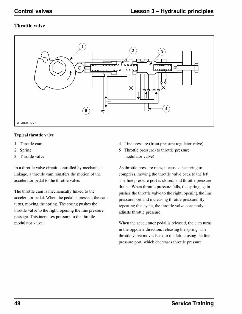
Typical throttle valve
1 Throttle cam
2 Spring
3 Throttle valve
ATX034-A/VF
12 3
45
4 Line pressure (from pressure regulator valve)
5 Throttle pressure (to throttle pressure
modulator valve)
In a throttle valve circuit controlled by mechanical
linkage, a throttle cam transfers the motion of the
accelerator pedal to the throttle valve.
The throttle cam is mechanically linked to the
accelerator pedal. When the pedal is pressed, the cam
turns, moving the spring. The spring pushes the
throttle valve to the right, opening the line pressure
passage. This increases pressure to the throttle
modulator valve.
As throttle pressure rises, it causes the spring to
compress, moving the throttle valve back to the left.
The line pressure port is closed, and throttle pressure
drains. When throttle pressure falls, the spring again
pushes the throttle valve to the right, opening the line
pressure port and increasing throttle pressure. By
repeating this cycle, the throttle valve constantly
adjusts throttle pressure.
When the accelerator pedal is released, the cam turns
in the opposite direction, releasing the spring. The
throttle valve moves back to the left, closing the line
pressure port, which decreases throttle pressure.

Service Training 49
Lesson 3 – Hydraulic principles Control valves
Throttle and governor pressures
Pressure from two separate circuits influences shift
timing: throttle pressure, which is based on engine
load; and governor pressure, which is based on road
speed.
Each of these circuits receives line pressure from the
pump and modifies it into a pressure signal. The
modified pressures developed in the throttle and
governor circuits exert force on the shift control
valves, just as fluid forced the piston to move in the
sample circuit described previously in this section.
Working with line pressure, the modified pressures
from the governor and throttle circuits control the
valves that automatically shift gears to match engine
load and road speed. The valves in the valve body
control fluid flow through circuits that connect line
pressure to the various bands and clutches that control
shifting.

50 Service Training
General Lesson 4 – Apply devices
Objectives
Upon completion of this lesson, you will be able to:
� Identify the components in a hydraulic multiple-disc clutch and describe their functions.
� Identify the components of a band and servo assembly and describe their functions.
� Describe the purpose of accumulator and modulator valves in the hydraulic control system.

Service Training 51
Lesson 4 – Apply devices At a glance
Clutches and bands
When an automatic transmission shifts gears, various
gear train components must rotate, while other
components are prevented from rotating. This section
describes how clutches and bands drive and hold gear
train members in an automatic transmission.
Clutches and bands perform opposite but
complementary functions in an automatic
transmission. Clutches drive gear train members,
forcing them to rotate. Bands, on the other hand, hold
gear train members, preventing them from rotating.
Clutch overview
The clutch in an automatic transmission is similar to a
manual clutch in that it connects and disconnects the
engine from the transmission. If you turn the input
shaft on an automatic transmission with the clutch
released, the output shaft does not turn. But if you
apply the clutch and turn the input shaft, the output
shaft turns because the clutch forms a mechanical link
between the two shafts.
Band overview
Instead of connecting two rotating parts, a band holds
a component and prevents it from rotating. When a
band is hydraulically applied, it clamps around a
drum and keeps it from turning. The band is anchored
to the transmission case, and its clamping force is
strong enough to prevent the drum from rotating.

52 Service Training
Clutches Lesson 4 – Apply devices
Multiple-disc clutch
Clutch housing and piston
Typical clutch housing and piston
1 Clutch housing
2 Piston seals
ATX035-A/VF
21
4
3
3 Piston
4 Snap ring
Automatic transmissions use a multiple-disc clutch.
The clutch assembly is made of several circular discs
that work together to connect and disconnect the
engine from the transmission.
Since the multiple-disc clutch is hydraulically
operated, it includes a piston that moves back and
forth in a clutch housing, or drum, when pushed by
pressurized fluid. The piston and clutch housing are
protected by seals that provide leak-proof surfaces
between the piston and housing. A snap ring limits the
amount of piston travel. Without the snap ring, the
pressurized fluid would “blow” the piston completely
out of the clutch housing.

Service Training 53
Lesson 4 – Apply devices Clutches
Clutch apply circuit
Hydraulic apply circuit
1 Piston seal (outer)
2 Clutch housing
3 Piston
4 Piston seal (inner)
5 Manual valve
6 Line pressure
To provide hydraulic flow to the clutch housing, a
passage connects line pressure from the valve body to
the housing.
The valve body controls fluid flow to the clutch
housing. When the engine is running, fluid from the
pump flows through the valve body into the clutch
housing, where it pushes on the piston.
ATX036-B/VF
5
4
3
21
6

54 Service Training
Clutches Lesson 4 – Apply devices
Multiple-disc clutch (continued)
Clutch return spring
Typical clutch drum and return spring
1 Clutch housing
2 Piston seals
3 Piston
4 Piston return spring assembly
5 Snap ring
To automatically reset the piston, the clutch assembly
includes return springs.
ATX037-A/VF
21
5
3
4

Service Training 55
Lesson 4 – Apply devices Clutches
Manual valve circuit
1 Piston return spring assembly
When fluid flow is cut off to the clutch housing, the
springs push the piston back into the housing, and the
fluid exhausts back through the circuit. Movement of
the manual valve applies and releases the clutch
piston.
ATX038-B/VF
2
1
2 Manual valve

56 Service Training
Clutches Lesson 4 – Apply devices
Multiple-disc clutch (continued)
Clutch pack
ATX039-A/VF
4
7
6
532
89
1
Typical clutch pack assembly
1 Clutch housing
2 Return spring
3 Snap ring
4 Steel plates
5 Snap ring
6 Pressure plate
7 Friction plates
8 Piston
9 Seals
To make the clutch functional, a clutch pack is
installed behind the spring assembly. A clutch pack is
a set of discs made up of two different types of plates.
One set of plates is made of steel, with tabs on the
outer diameter. The other plates are covered with a
friction material similar to brake lining. These friction
plates also have splines on their inner diameters.
The tabs on the steel plates fit into grooves machined
into the inside diameter of the clutch housing. So
when the clutch housing rotates, the steel plates also
turn. The friction plates, on the other hand, are not
directly connected to the clutch housing. They do not
rotate with the clutch housing unless they press
tightly against the steel plates.

Service Training 57
Lesson 4 – Apply devices Clutches
Pressure plate cut-away
1 Steel plates
2 Clutch pack
3 Snap ring
4 Pressure plate
5 Manual valve
The clutch pack alternates steel plates and friction
plates. The last plate in the stack is the pressure plate.
It is thicker than the other steel plates so it strengthens
the clutch pack. The pressure plate also keeps the
clutch pack from bending when the piston is applied.
The snap ring on the end of the clutch pack holds the
plates in the clutch housing.
The clutch assembly mounts on the transmission
input shaft, where splines on the inside diameter of
the clutch housing mesh with splines on the input
shaft. Since the input shaft is linked to the crankshaft
through the torque converter, the clutch housing
rotates when the engine is running.
ATX040-B/VF
2
3
4
5
1
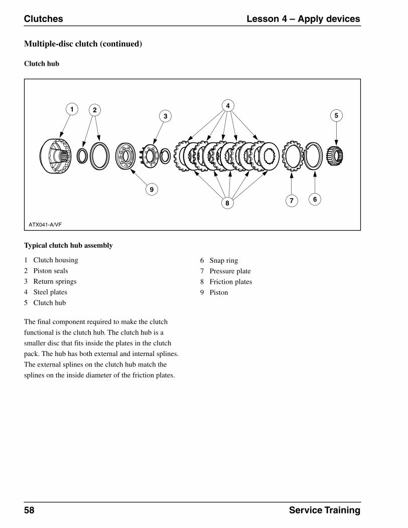
58 Service Training
Clutches Lesson 4 – Apply devices
Multiple-disc clutch (continued)
Clutch hub
ATX041-A/VF
4
8
32
9
15
67
Typical clutch hub assembly
1 Clutch housing
2 Piston seals
3 Return springs
4 Steel plates
5 Clutch hub
6 Snap ring
7 Pressure plate
8 Friction plates
9 Piston
The final component required to make the clutch
functional is the clutch hub. The clutch hub is a
smaller disc that fits inside the plates in the clutch
pack. The hub has both external and internal splines.
The external splines on the clutch hub match the
splines on the inside diameter of the friction plates.

Service Training 59
Lesson 4 – Apply devices Clutches
Clutch and hub cut-away
1 Friction plate, stationary
2 Clutch hub, stationary
3 Friction plate, rotating
4 Clutch hub, rotating
5 Manual valve
When fluid flow to the clutch housing is cut off, the
piston moves back in the clutch housing and the
clutch releases. The friction plates do not rotate since
they are not connected to the clutch housing. Because
the hub is splined to the friction plates, it also remains
stationary.
ATX042-A/VF
1 3
4
55
2

60 Service Training
Bands Lesson 4 – Apply devices
Bands and servos
8 Servo cover
9 Cover O-rings
10 Retainer snap ring
11 Snap ring
12 Drum and gear assembly
13 Anchor strut
Typical band and servo assembly
1 Pin
2 Band
3 Piston rod
4 Cushion spring
5 Return spring
6 Piston
7 Piston seals
ATX043-A/VF
The hydraulic system either holds or drives gear train
components to provide the different gear
combinations required in an automatic transmission.
While clutches drive gear train components, bands are
used to hold them.
The held member of a gear set is mechanically
connected to a drum, with the band surrounding the
drum. Friction material covers the inside surface of
the band, allowing the band to grip the drum surface
and prevent it from turning.
One end of the band is anchored to the transmission
case, while the other end connects to a hydraulic
device called a servo. A servo is a hydraulically
applied piston.

Service Training 61
Lesson 4 – Apply devices Bands
Band operation
Typical band applied
1 Piston rod
2 Return spring
3 Release passages
4 Boost passage
5 Apply passage
6 Cover
7 Piston
8 Servo assembly
9 Band
10 Anchor strut
ATX044-A/VF
21
7
8
6
10
9
3
4
5
A case contains the servo, its springs, and hydraulic
passages. A rod extends from the servo piston to the
free end of the band. To squeeze the ends of the band
together, hydraulic pressure pushes the servo piston
through the bore. This motion forces the piston rod
against the end of the band, squeezing the band
around the drum. When pressure is released, the
return springs move the piston back into the bore, and
the band releases the drum.
When the servo has to provide an extremely tight grip
on the band, the hydraulic system opens an additional
passage on the applying side of the piston. This
additional force, or boost pressure, holds the drum
against the stronger torque generated by lower gears.
To release the band quickly, hydraulic pressure and
spring tension work together. A shift valve in the
valve body moves to open a “release” port. This port
allows fluid to push against the release side of the
piston while fluid is also present on the apply side.
Because the release pressure side has a larger surface
area than the apply side, it can overcome the apply
pressure.

62 Service Training
Accumulators and modulators Lesson 4 – Apply devices
Purpose of accumulators and modulators
If the various oil circuits are traced, accumulator
pistons, modulator valves, and accumulator valves are
connected to the clutch and band circuits. These
hydraulic controls “fine-tune” fluid flow to the
various circuits so the amount of apply pressure
matches the amount of torque directed through the
transmission.
When the engine is operating with light throttle, a
small amount of torque passes through the
transmission, so the apply pressures can be reduced.
With heavy throttle, engine torque increases greatly,
so the hydraulic apply pressures are also increased.
If apply pressure does not match engine torque, the
transmission does not operate smoothly. For example,
high apply pressure at low torque causes harsh
shifting, which may damage transmission
components. On the other hand, low apply pressure
with high torque causes slow engagement and
slipping of transmission components. Excessive
slipping produces heat, which can burn the friction
material applied to many transmission parts.
The transmission regulates apply pressures in three
different ways. First, modulator valves control, or
modulate, line pressure by restricting flow (and
pressure) through their outlet ports. Second,
accumulator valves “cushion” the amount of apply
pressure. Finally, accumulator pistons absorb some of
the fluid pressure applied to servo pistons.
Accumulator and modulator valves are located in the
valve body. Accumulator pistons may be part of the
servo piston assembly, or they may reside in their own
bores.

Service Training 63
Lesson 5 – Planetary gear sets General
Objectives
Upon completion of this lesson, you will be able to:
� Identify the components in a basic planetary gear set and describe their operation.
� Describe the basic differences between a simple (Simpson) gear train and a compound (Ravigneaux)
gear train.
� Describe powerflow in a simple (Simpson) gear train.

64 Service Training
At a glance Lesson 5 – Planetary gear sets
Purpose of a planetary gear set
Simple planetary gear set
1 Ring gear
2 Sun gear
3 Planet carrier
4 Planet gears (pinions)
The gear train in an automatic transmission transmits
engine torque from the input shaft to the output shaft.
The gear train includes a planetary gear set that
provides the gear ratios required to move the vehicle.
This section describes how planetary gear sets work,
and describes two different types of planetary gears.
A planetary gear set gets its name from the
arrangement of the gears in the set. The gears revolve
around a central gear in the same way that the planets
in the solar system revolve around the sun. In fact, the
revolving gears are called planet gears (or pinion
gears), and the central gear is called the sun gear.
A typical planetary gear set has the sun gear at the
center. Around the sun gear is a ring with gear teeth
cut into its inside diameter. This ring is the ring (or
internal) gear.
The planet gears connect the sun gear to the ring gear.
The teeth on the planet gears mesh with both the sun
gear and the ring gear. The planet gears are mounted
on shafts that are interconnected through the planet
carrier.
Therefore, a planetary gear set includes three
members: the sun gear, the planet carrier, and the ring
gear. By holding or driving the members in various
combinations, a planetary gear set can produce three
basic types of gear ratios:
� Reduction (low gear)
� Direct drive (high gear)
� Reverse
A compound, or Ravigneaux, gear set can produce an
additional gear ratio called overdrive, which is
described later in this section.
ATX003-C/VF
1
2
3
4

Service Training 65
Lesson 5 – Planetary gear sets Operation
Reduction
Planetary gear set in reduction
1 Planet gears “walk” around sun gear
2 Ring gear is driven
3 Planet carrier rotates
ATX046-A/VF
3
2
1
When the sun gear is held and the planet carrier drives
the ring gear, rotation of the ring gear makes the
planet gears “walk” around the sun gear in the same
direction the ring gear is turning. However, the planet
gears turn slower than the ring gear, reducing the
rotation speed of the output shaft.
Reduction refers to the operation of lower gear ratios,
where the output shaft turns slower than the input
shaft. A vehicle accelerating from a stop begins in low
gear so that engine speed can be transferred smoothly
to the drive wheels of the vehicle.

66 Service Training
Operation Lesson 5 – Planetary gear sets
Direct drive
ATX047-A/VF
1
2
3
Planetary gear set direct drive
1 Planet carrier
2 Sun and ring gears are locked
3 Output shaft
In direct drive, the input and output shaft turn at the
same speed. To achieve direct drive, any two members
of the planetary gear set are held, forcing the set to
turn as a single unit. In this illustration, the ring gear
and sun gear are held, and the planet carrier applies
direct drive to the output shaft.

Service Training 67
Lesson 5 – Planetary gear sets Operation
Reverse
2 Planet carrier is held
Planetary gear set in reverse
1 Planet gears turn counterclockwise
To produce reverse output, the planet carrier is held
and the sun gear is driven. In this situation, the planet
gears simply turn on their shafts, acting as idler gears.
An idler gear reverses the direction of rotation.
For example the sun gear rotates clockwise, while the
planet carrier is held. This forces the planet gears to
turn counterclockwise, which also causes the ring
gear to turn counterclockwise.
ATX048-B/VF
2
1

68 Service Training
Types Lesson 5 – Planetary gear sets
Simple and compound gear trains
Simpson gear train exploded view
1 Output shaft
2 Low/reverse band
3 Low/reverse drum and one-way clutch
4 Output shaft ring gear
5 Reverse planet assembly
6 Input shaft
7 Intermediate band
8 Reverse/high clutch and drum
9 Forward clutch
10 Forward clutch hub and ring gear
11 Front planet assembly
13 Input shell
12 Sun gear
Two different types of planetary gear sets are used in
most vehicles: the simple, or Simpson gear train; and
the compound, or Ravigneaux, gear train.
The simple gear train contains two separate planetary
gear assemblies, one for forward motion and one for
reverse.
The compound gear train uses two planet carriers and
two ring gears with a common sun gear.
ATX049-B /VF
1
4
13 1110
9
8
7
5
6
12
23

Service Training 69
Lesson 5 – Planetary gear sets Simpson gear train
Powerflow
Neutral
Simple gear train assembled
1 Input shaft
2 Forward clutch
The simple gear train produces the following gear
ranges:
� Neutral
� Reduction (first and second gears)
� Direct drive
� Reverse
In neutral, the converter turbine drives the input shaft,
which drives the clutch housing. Because no clutch is
applied, there is no further transfer of engine power.
ATX051-B /VF
1
2

70 Service Training
Simpson gear train Lesson 5 – Planetary gear sets
Powerflow (continued)
First gear (low)
Simple gear train powerflow
1 Output shaft
2 Low/reverse drum and one-way clutch
3 Output shaft ring gear
4 Reverse planetary assembly
5 Input shaft
6 Forward clutch
7 Forward clutch hub and ring gear
8 Forward planetary assembly
9 Sun gear
ATX050-B /VF
1
4
87
6
5
9
2
3

Service Training 71
Lesson 5 – Planetary gear sets Simpson gear train
In first gear, powerflow is as follows:
� The converter turbine drives the input shaft
clockwise.
� The input shaft drives the forward clutch housing
clockwise.
� The forward clutch is applied, locking the input
shaft to the front planetary ring gear. The input
shaft drives the forward clutch ring gear
clockwise.
� The forward clutch ring gear drives the front
planet gears clockwise.
� The front planet gears drive the sun gear
counterclockwise.
� The sun gear drives the reverse planet gears
clockwise.
� A one-way clutch holds the reverse planet carrier
stationary.
� The reverse planet gears drive the output shaft ring
clockwise.
� The output shaft ring gear drives the output shaft
clockwise.

72 Service Training
Simpson gear train Lesson 5 – Planetary gear sets
ATX052-B /VF
1
9 76
5
4
3
2
8
Powerflow (continued)
Second gear (intermediate)
Simple gear train powerflow
1 Output shaft
2 Input shaft
3 Intermediate band
4 Reverse/high clutch and drum
5 Forward clutch
6 Forward clutch hub and ring gear
7 Front planetary assembly
8 Sun gear
9 Input shell

Service Training 73
Lesson 5 – Planetary gear sets Simpson gear train
In second gear, powerflow is as follows:
� The converter turbine drives the input shaft
clockwise.
� The input shaft drives the forward clutch housing
clockwise.
� The forward clutch is applied, driving the forward
ring gear clockwise.
� The intermediate band holds the intermediate band
drum. This drum connects to the sun gear and
input shell, which are also held.
� The forward ring gear drives the front planetary
gears clockwise. The planetary gears “walk”
around the stationary sun gear.
� The front planet gears force the front planet carrier
to turn clockwise.
� The front planet carrier turns the output shaft
clockwise.

74 Service Training
Simpson gear train Lesson 5 – Planetary gear sets
Powerflow (continued)
Third gear (high)
ATX053-B /VF
1
8 65
4
3
2
7
Simple gear train powerflow
1 Output shaft
2 Input shaft
3 Reverse/high clutch and drum
4 Forward clutch
5 Forward ring gear
6 Front planetary assembly
7 Sun gear
8 Input shell

Service Training 75
Lesson 5 – Planetary gear sets Simpson gear train
In third gear (high), powerflow is as follows:
� The converter turbine drives the input shaft
clockwise.
� The input shaft drives the forward clutch housing
clockwise.
� The forward clutch housing also forms the hub of
the reverse/high clutch.
� The forward and reverse/high clutches are both
applied.
� The forward clutch drives the applied reverse/high
clutch clockwise.
� The reverse/high clutch drives the input shell and
sun gear clockwise.
� The forward clutch drives the forward ring gear
clockwise.
� The forward ring gear drives the front planet gears
clockwise.
� Because the front planet gears are being driven by
both the sun gear and the forward ring gear, a
“lock-up” occurs. The front planet gears drive the
front planet carrier.
� The front planet carrier is splined to the output
shaft and drives it clockwise.

76 Service Training
Simpson gear train Lesson 5 – Planetary gear sets
ATX054-B /VF
1
4
10
8
7
5
6
23
9
Powerflow (continued)
Reverse gear
Simple gear train powerflow
1 Output shaft
2 Low/reverse band
3 Reverse/low drum and one-way clutch
4 Reverse ring gear
5 Reverse planetary assembly
6 Input shaft
7 Reverse/high clutch and drum
8 Forward clutch
9 Sun gear
10 Input shell

Service Training 77
Lesson 5 – Planetary gear sets Simpson gear train
In reverse gear, powerflow is as follows:
� The converter turbine drives the input shaft
clockwise.
� The input shaft drives the forward clutch housing
clockwise.
� The forward clutch housing also forms the hub of
the reverse/high clutch.
� The forward and reverse/high clutches are applied.
The forward clutch drives the applied reverse-high
clutch clockwise.
� The reverse/high clutch drives the input shell and
sun gear clockwise.
� The low/reverse band holds the low/reverse drum
and reverse planet gear carrier stationary.
� The sun gear drives the reverse planet gears
counterclockwise.
� The reverse planet gears drive the output shaft
counterclockwise.
78 Service Training
Operation Lesson 5 – Planetary gear sets
Advantages of planetary gear sets
Any time the planetary gear set members are driven
or held, the gears are always in mesh. Therefore, they
never “clash” or “grind” as gears sometimes do in a
manual transmission. In addition, the arrangement of
the planetary gear set allows several gear teeth to be
in contact at any time. This means the gear set
distributes torque loads over a wider area, resulting in
a stronger gear set.
Another advantage of the planetary gear set is the
compact size of the gear train. Unlike a manual
transmission, which uses a cluster gear and separate
shafts, the automatic transmission has planetary gear
shafts mounted on a common centerline.

Service Training 79
Lesson 5 – Planetary gear sets Operation
Compound gear train
Compound planetary gear set
1 Long planet gear
2 Short planet gear
3 Sun gear
4 Ring gear
The second type of planetary gear set used in some
vehicles is the compound, or Ravigneaux, gear train.
A compound gear train uses two planet carriers and
two ring gears with a common sun gear. Each planet
carrier contains several pairs of planet gears. One gear
in each pair is the long planet gear; the other is the
short planet gear.
ATX055-A/VF
3
21
4

80 Service Training
General Lesson 6 – Transaxle
Objectives
Upon completion of this lesson, you will be able to:
� Identify the components of a transaxle chain drive and describe their functions.
� Identify the components of a transaxle final drive unit and describe their functions.
� Describe the differences between idler gear systems and chain drive (in-line) systems.
� Identify the components of a transaxle differential assembly and describe their functions.
� Describe how the transaxle differential assembly operates with the wheels straight and with the wheels turned.

Service Training 81
Lesson 6 – Transaxle At a glance
Transaxle theory
Transaxle cut-away
1 Output gear
2 Idler gear
3 Side gear
4 Pinion gear
5 Pinion shaft
6 Differential gear case
7 Ring gear
A transaxle is a transmission for a front-wheel drive
vehicle. Most of the principles that apply to rear-
wheel drive transmissions also apply to transaxles.
This section describes the differences that are unique
to transaxles.
ATX071-A/VF
2
1
3
4
67
5
In a rear-wheel drive vehicle, power flows from front
to rear – from the engine to the torque converter and
input shaft, through the gear train to the output shaft,
and through the rear axle to the rear wheels.

82 Service Training
At a glance Lesson 6 – Transaxle
Transaxle theory (continued)
In front-wheel drive vehicles, however, power must be
redirected to the front wheels. To accomplish this, a
transaxle has a final drive/differential built inside the
transaxle case. Placing the final drive unit in the case
allows for a smaller package, which fits in the limited
space of the engine compartment. In addition, an
internal final drive allows the rotation of the transaxle
planetary units to match the rotation of the wheels.
By definition, transaxles must change the direction of
powerflow inside the unit. In most transaxles, either
an idler gear system or a chain drive alters the
direction of powerflow.

Service Training 83
Lesson 6 – Transaxle Systems
Chain drive system
7 Drive gear
8 Chain
9 Converter housing
10 Torque converter
11 Final drive and differential
Transaxle exploded view
1 Planet assembly
2 Planetary ring gear
3 Sun gear and drum
4 Clutch pack
5 One-way clutch
6 Planet assembly
ATX072-A/VF
11
8
10
9
76
3
4
5
1
2
In a chain drive system, the transaxles final drive is in
line with the planetary gear train.
A chain drive transfers torque from the planetary gear
sets to the final drive. The chain drive includes:
� Drive sprocket
� Driven sprocket
� Silent-type drive chain
The reverse/overdrive ring gear is an integral part of
the drive sprocket. The final drive sun gear and
parking gear are integral parts of the driven sprocket.

84 Service Training
Final drive Lesson 6 – Transaxle
Chain drive system (continued)
Purpose
A transaxle final drive serves the same purpose as the
rear axle differential assembly in a rear-wheel drive
vehicle. That is, the final drive:
� allows the output rotation of the planetary gear set
and the final drive to remain in the same direction.
� supplies the vehicle’s final gear reduction.
� compensates for differences in axle rotation speeds
when the vehicle is turning.

Service Training 85
Lesson 6 – Transaxle Components
Idler gear type
Transaxle cut-away
1 Output gear
2 Idler gear
3 Ring gear
4 Differential case
ATX073-A/VF
1
2
3
4
Final drive components vary with the type of
transaxle drive. A typical idler gear final drive
assembly includes the final drive output gear,
differential case, side gears, and pinion gears.
In an idler gear system, the final drive of the transaxle
is parallel to the planetary gear train. The idler gear
system changes the direction of power output.
A final drive input gear (ring gear) connects to the
planet carrier. The carrier drives this gear in the same
direction and at the same speed as the carrier.
An idler gear transmits input gear torque to the output
gear, so the direction of rotation is the same. The idler
gear rests on two tapered roller bearings on the idler
gear shaft. This shaft is supported by the transfer gear
housing and transaxle case.

86 Service Training
Components Lesson 6 – Transaxle
Idler gear type (continued)
The output gear corresponds to the ring gear in a rear-
wheel drive gear train. It attaches to the differential
case, where it is driven by the idler gear. The output
gear always turns in the same direction as the input
gear.

Service Training 87
Lesson 6 – Transaxle Components
Chain drive type
5 Pinion shaft
6 Side gear
7 Pinion gear
Chain drive differential
1 Halfshaft
2 Differential carrier
3 Final drive gear
4 Halfshaft
The final drive of a typical in-line chain drive system
includes a planetary gear set that transfers and
multiplies torque from the drive chain to the
differential.
The final drive includes a:
� Sun gear (integral with the driven sprocket)
� Carrier (integral with the differential case)
� Ring gear
A differential case holds the side gears, the governor/
speedometer drive gear, and the final drive pinion
gears.
Two differential pinion gears (and washers) mount on
the pinion shaft. A pinion pin retains the shaft in the
differential case. Two side gears (with washers) mesh
with the differential pinion gears. The right gear is
splined to the right halfshaft assembly, and the left
gear is splined to the transaxle output shaft.
ATX074-A/VF
1
2
4
3
5
6
7

88 Service Training
Differential assembly Lesson 6 – Transaxle
Operation – wheels straight
Differential cut-away – straight ahead driving
1 Pinion gears
2 100 rpm
3 Differential case
4 Side gears and halfshafts
5 100 rpm
When the vehicle is driven straight ahead, power
flows through the differential.
� The final drive gear set turns the differential case.
� The pinion shaft and differential pinion gears drive
the side gears. The side gears do not spin when the
vehicle is driving straight ahead, but move as a
unit. The side gears spin only when there is a
speed difference between the left and right drive
axles.
� The side gears drive the output shaft and right
halfshaft at the same speed. The output shaft is
splined to the left halfshaft. Each halfshaft drives
its own wheel.
Both wheels receive the same amount of torque, about
half the torque that is transmitted to the differential
case.
ATX075-A/VF
1
3
5
2
4

Service Training 89
Lesson 6 – Transaxle Differential assembly
ATX076-A/VF
21
Operation – wheels turned
Tires traveling different distances during a turn
1 Inside wheel (rotates slower)
2 Outside wheel (turns faster)
When a vehicle is turning, the outer wheel must rotate
faster than the inner wheel because the outer wheel
has to travel a longer distance in the same amount of
time.

90 Service Training
Differential assembly Lesson 6 – Transaxle
ATX077-A/VF
1
3
2
74
6 5
Operation – wheels turned (continued)
Differential cut-away – driving around a curve
1 Pinion shaft
2 80 rpm
3 Side gear
4 Pinion gear
5 Differential carrier
6 Side gear
7 120 rpm
When one wheel is turning faster than the other,
power flows through the differential.
� The final drive gear set turns the differential case.
� The pinion shaft and differential pinion gears drive
the side gears.
� The side gear driving the inner wheel rotates
slower than the outer wheel (or not at all).
� The differential pinion gears “walk around” the
slower moving side gear, rotating on the pinion
shaft.
� The pinions drive the side gear on the outer wheel
faster than the inner wheel side gear.
The torque is split proportionally between the two
wheels. For example, the inner wheel may rotate at
80 percent of the speed of the differential case, while
the outer wheel rotates at 120 percent of case speed.

Service Training 91
Lesson 7 – Electronic controls General
Objectives
Upon completion of this lesson, you will be able to:
� Describe how an electronic control system directs the operation of an automatic transmission.
� Identify the input sensors used in an electronic control system and describe how they operate.
� Describe the three types of solenoids used as system outputs.
� Identify the output solenoids used in an electronic control system and describe how they operate.

92 Service Training
At a glance Lesson 7 – Electronic controls
Control systems
The electronic control system for an automatic
transmission reads information supplied by vehicle
sensors and translates the data into output signals.
These signals operate solenoids that control shift
timing, shift feel, and torque converter clutch
operation. This section identifies the parts of the
electronic control system and describes how they
operate.
Up to this point, we have described the basic theory
and operation of hydraulically actuated transmissions.
Because of improvements in technology, the governor
and vacuum modulator systems used on hydraulically
actuated transmissions have been replaced with
electric solenoids, switches, and sensors.
The benefits of electronically controlled automatic
transmissions are:
� Increased fuel economy and performance
� Improved shift quality
� Reduced noise and vibration
� More driver control
� Self-diagnosis
Electronic theory
The electronic control system is a specialized
computer system that reads input signals from various
sensors located in the vehicle. Based on the
information provided by these sensors, the electronic
control system sends output signals that operate
various solenoids. (A solenoid is a type of electric
switch that includes a wire coil. When current is
applied, the coil is magnetized. The magnetic field
moves a rod-shaped component that opens and closes
the switch.) These solenoids control the hydraulic and
mechanical functions that make the transmission
operate. The electronic control system specifically
directs shift timing, line pressure adjustment, and
converter clutch operation.

Service Training 93
Lesson 7 – Electronic controls System inputs
Control module theory
The “brain” of the electronic control system is a
module that contains electronic circuit boards,
microprocessor chips, and input and output
connectors.
Using the information the control module receives
from the input sensors, the control module computes
engine load, vehicle speed and conditions, and
transmission conditions. The control module then
controls the output solenoids by selectively grounding
or applying voltage to certain electrical circuits.
Input and output signals
Some input signals come from engine-related sensors,
such as the mass air flow sensor, intake air
temperature sensor, and engine coolant temperature
sensor. These sensors give the control module
information about the engine’s current operating state.
Other inputs are based on the driver’s demands. For
example, the throttle position sensor relays
information about the position of the accelerator
pedal. Still other inputs come from the transmission
itself. For example, sensors provide information about
output shaft speed, transmission fluid temperature,
and gear range selection.
Using all these input signals, the control module
determines when the time and conditions are right for
a shift or a converter clutch application. The control
module also determines the line pressure needed for
the smoothest shift operation (also called shift feel).
To accomplish these functions, the control module
typically controls four electronic solenoids: two for
shifting, one for modulating the converter clutch, and
one for controlling line pressure.

94 Service Training
System inputs Lesson 7 – Electronic controls
Control module inputs
System inputs and outputs
1 Engine inputs
2 Transmission range sensor
3 Input shaft speed (ISS) sensor
4 Output shaft speed (OSS) sensor
5 Vehicle speed sensor (VSS)
8
7
9
10
1
2
3
4
5
6
ATX078-B/VF
6 Transmission fluid temperature (TFT) sensor
7 Control module
8 Torque converter clutch control solenoid
9 Shift solenoids
10 Electronic pressure control solenoid

Service Training 95
Lesson 7 – Electronic controls System inputs
There are two basic types of control module input
signals:
� Inputs related to items outside the transmission,
such as the engine coolant and air conditioning
clutch. These inputs include sensors that measure
engine and driver demands.
� Inputs related to the transmission itself, such as
output shaft speed and transmission fluid
temperature.
These input signals are described on the following
pages. The descriptions assume you are familiar with
terms related to automotive electrical systems.

96 Service Training
System inputs Lesson 7 – Electronic controls
Control module inputs (continued)
3 Manual lever shaft
4 Adjustment
ATX079-A/VF
1
2
3
4
Transmission range (TR) sensor
1 Electrical connector
2 Adjustment
The transmission range (TR) sensor is located on the
transmission case at the manual lever position. This
sensor includes a series of step-down resistors that act
as a voltage divider. The control module constantly
monitors voltage readings in the TR sensor to
determine the position of the manual lever
(for example, P, R, N, D, or 1).

Service Training 97
Lesson 7 – Electronic controls System inputs
ATX080-A/VF
Output shaft speed (OSS) sensor and input shaft speed (ISS) sensor
The output shaft speed (OSS) sensor and input shaft
speed (ISS) sensor are magnetic pickups. The OSS
sensor sends a voltage signal to the control module
that is proportional to the rotation speed of the output
shaft ring gear. The ISS sensor sends a voltage signal
to the control module that is proportional to the
rotation speed of the input shaft. The control module
uses this information to schedule shifts, adjust line
pressure, and control the converter clutch.

98 Service Training
System inputs Lesson 7 – Electronic controls
Control module inputs (continued)
ATX081-A/VF
Vehicle speed sensor (VSS)
The vehicle speed sensor (VSS) is a magnetic pickup
mounted near the rear of the transmission. Driven by
a small gear, the VSS sends a voltage signal to the
control module that is proportional to the rotation
speed of the output shaft. The control module uses
this signal as auxiliary input for modifying upshift
scheduling only. (The OSS sensor provides the
primary vehicle speed information to the control
module.)
Some vehicles use a vehicle speed signal from a
different system such as the ABS system.

Service Training 99
Lesson 7 – Electronic controls System inputs
ATX083-B/VF
21
3
4
5
Pulse-width modulated (PWM) solenoid
1 Connector
2 Coil
3 Armature
4 Push rod
5 Ball valve
A pulse-width modulated (PWM) solenoid controls
the application and release of the torque converter
clutch. When applied, this clutch locks the turbine and
converter cover together, forming a mechanical link
between the engine and the transmission input shaft.
The control module signals this solenoid to allow an
appropriate amount of fluid into the converter clutch
control valve. The amount of pressurized fluid
controls the movement of the clutch piston. This
solenoid is also called the torque converter clutch
control (TCC) solenoid.

100 Service Training
System inputs Lesson 7 – Electronic controls
Control system outputs
Using input from the various sensors on the vehicle,
the control module outputs signals to solenoids that
control transmission operation.
Solenoid types
Three different types of solenoids are used as output
devices:
� Pulse-width modulated solenoid – controls the
converter clutch
� On/off solenoid – turns flow on or off to the shift
valves
� Variable force solenoid – adjusts shift feel by
controlling line pressure

Service Training 101
Lesson 7 – Electronic controls System inputs
The control module uses the TFT sensor signal to
determine whether or not a “cold-start” shift schedule
is required. When the transmission fluid is cold, the
control module modifies normal shift scheduling and
prevents the converter clutch from engaging.
The control module also uses the TFT sensor signal to
lock-up the torque converter to reduce oil
temperature.
Transmission fluid temperature (TFT) sensor
1 Thermistor
2 Wire
3 Connector pins
The transmission fluid temperature (TFT) sensor is a
temperature-sensitive thermistor located on the
transmission control valve body. Its resistance value
varies with the temperature of the transmission fluid.
The control module measures the voltage across the
TFT sensor to determine fluid temperature.
ATX082-A/VF
1 2 3

102 Service Training
System outputs Lesson 7 – Electronic controls
Control system outputs (continued)
ATX084-A/VF
2
1
On/off solenoid
1 Shift solenoid one 2 Shift solenoid two
Two or three simple on/off solenoids mounted in a
single housing control fluid flow to the shift valves.
The solenoids may be called shift solenoid 1 (SS1)
and shift solenoid 2 (SS2), or shift solenoids A, B,
and C. These solenoids do not regulate the amount of
fluid in the passages, they simply turn the flow on or
off.

Service Training 103
Lesson 7 – Electronic controls System outputs
Variable force solenoid (VFS)
1 Coil
2 Armature
3 Electrical connector
ATX085-B/VF
5
1
2
3
4
4 Valve
5 Springs
A variable force solenoid (VFS) controls shift feel by
adjusting line pressure to match engine and
transmission conditions, as well as driver demands.
By adjusting line pressure to match conditions, the
electronic control system provides smoother shifts.
The VFS that controls line pressure is called the
electronic pressure control (EPC) solenoid.

104 Service Training
System outputs Lesson 7 – Electronic controls
Solenoid operations
ATX086-A/VF
2
6
7
5
4
3
1
Torque converter clutch control (TCC) solenoid
1 Electrical connector
2 Coil
3 Armature
4 Armature pushrod
5 Ball valve
6 Fluid flow
7 Variable fluid output to converter clutch

Service Training 105
Lesson 7 – Electronic controls System outputs
The torque converter clutch control (TCC) solenoid
supplies the clutch with full pressure, no pressure, or
varying amounts of pressure. When the ball valve is
closed, no pressurized fluid flows to the clutch control
valve, and the clutch is released. When the ball valve
is fully open, full pressure flows to the clutch, and it
applies.
The TCC solenoid can also supply partial flow to the
clutch for slip lock. During slip lock-up, the control
module rapidly turns the solenoid on and off for
varying lengths of time. The ball valve opens and
closes, sending fluid in brief pulses to the clutch
control valve. In this way, the TCC solenoid
modulates pressure to the clutch, which enhances
transmission smoothness and fuel economy.

106 Service Training
System outputs Lesson 7 – Electronic controls
Solenoid operations (continued)
ATX087-A/VF
1
2
3
46
5
7
10 9
8
Electronic shift control solenoids
1 Spring
2 Coil
3 Exhaust to sump
4 Fluid from solenoid regulator valve
5 Ball valve open
6 Reduced fluid pressure to shift valve
7 Armature
8 Ball valve seated
9 Fluid from solenoid regulator valve
10 Full fluid pressure to shift valve
The control module controls automatic shift points by
sending signals to the on/off shift control solenoids.
The solenoids can be turned on or off in different
combinations. These combinations determine which
shift valves operate. For example, SS1 is on and SS2
is off in manual first gear. In second gear, only SS2 is
on.
The shift control solenoids are normally off unless
electrically activated by the control module. When the
solenoid is off, the ball valve opens and fluid flows
back to the sump. When the solenoid is on, the ball
valve closes, and fluid flows to the shift valves.
Unlike the TCC solenoid, the electronic shift control
solenoids have only two states, open or closed. They
cannot provide partial flow.
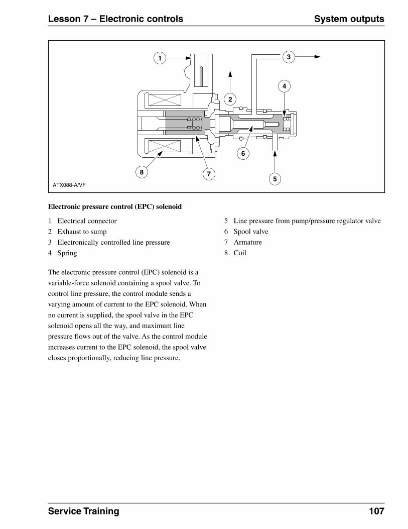
Service Training 107
Lesson 7 – Electronic controls System outputs
Electronic pressure control (EPC) solenoid
1 Electrical connector
2 Exhaust to sump
3 Electronically controlled line pressure
4 Spring
5 Line pressure from pump/pressure regulator valve
6 Spool valve
7 Armature
8 Coil
ATX088-A/VF
1
4
85
6
7
3
2
The electronic pressure control (EPC) solenoid is a
variable-force solenoid containing a spool valve. To
control line pressure, the control module sends a
varying amount of current to the EPC solenoid. When
no current is supplied, the spool valve in the EPC
solenoid opens all the way, and maximum line
pressure flows out of the valve. As the control module
increases current to the EPC solenoid, the spool valve
closes proportionally, reducing line pressure.

108 Service Training
General Lesson 8 – Diagnostic process
Objective
Upon completion of this lesson you will be able to:
� Explain the symptom-to-system-to-component-to-cause diagnostic process.

Service Training 109
Lesson 8 – Diagnostic process At a glance
Symptom-to-system-to-component-to-cause diagnostic process
Diagnosis requires a complete knowledge of the
system operation. As with all diagnosis, a technician
must use symptoms and clues to determine the cause
of a vehicle concern. To aid the technician when
diagnosing vehicles, the strategies of many successful
technicians have been analyzed and incorporated into
a diagnostic strategy and into many service
publications.
Symptom-to-system-to-component-to-causediagnostic process
Using the Symptom-to-System-to-Component-to-
Cause (SSCC) diagnostic process provides you with a
logical method for correcting customer concerns:
� First, confirm the “Symptom” of the customer’s
concern.
� Next, determine which “System” on the vehicle
could be causing the symptom.
� Once you identify the particular system, determine
which “Component(s)” within that system could
be the cause for the customer concern.
� After determining the faulty component(s) you
should always try to identify the cause of the
failure.
In some cases parts just wear out. However, in other
instances something other than the failed component
is responsible for the problem.
For example, if a torque converter clutch is damaged
because of a bad torque converter solenoid, replacing
the torque converter assembly may correct the
problem. However, if the solenoid that caused the
torque converter clutch failure is not corrected at the
same time, the torque converter clutch will certainly
fail again.
SSCC Diagram
1 Symptom
2 Vehicle systems
3 Components
4 Causes
ATX091-A/VF
1
2
3 3
2 2
4 4 4
3 3 3 3 3
110 Service Training
At a glance Lesson 8 – Diagnostic process
Workshop literature
The vehicle workshop literature contains information
for diagnostic steps and checks such as: preliminary
checks, verification of customer concern, special
driving conditions, road tests and diagnostic pinpoint
tests.

Service Training 111
List of abbreviations Automatic transmissions
SSCC Symptom-to-System-to-Component-
to-Cause
TV Throttle Valve
TCC Torque Converter Clutch
TCM Transmission Control Module
TFT Transmission Fluid Temperature
TR Transmission Range
Turbine shaft Input shaft
VFS Variable Force Solenoid
VSS Vehicle Speed Sensor
ATF Automatic Transmission Fluid
EPC Electronic Pressure Control
Input shaft Turbine shaft
OSS Output Shaft Speed
Planetary Pinion gear
gears
Planetary Planetary internal gear
ring gear
PSI Pounds per Square Inch
PWM Pulse-Width Modulated
SS1 Shift Solenoid 1
SS2 Shift Solenoid 2