Technical Report UDC 621 . 771 . 237 . 016 . 2 : 62 - 523 ... solve the problem, a control method of...
6
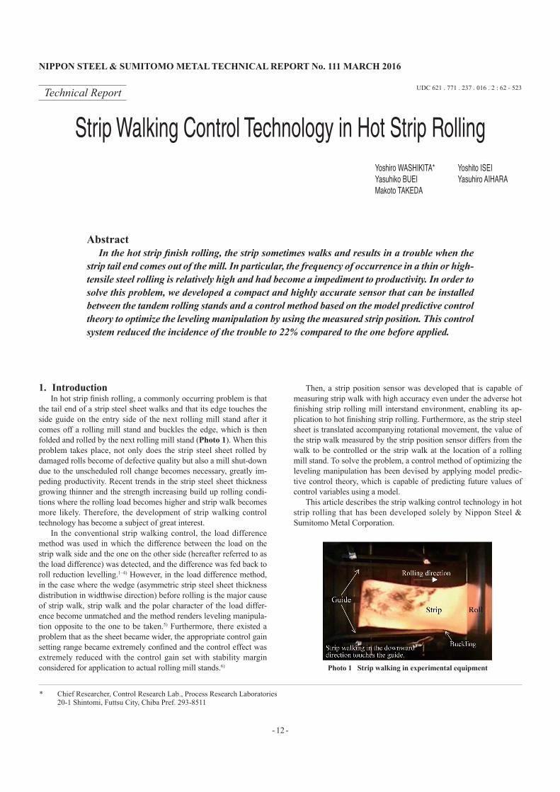
NIPPON STEEL & SUMITOMO METAL TECHNICAL REPORT No. 111 MARCH 2016 - 12 - 1. Introduction In hot strip finish rolling, a commonly occurring problem is that the tail end of a strip steel sheet walks and that its edge touches the side guide on the entry side of the next rolling mill stand after it comes off a rolling mill stand and buckles the edge, which is then folded and rolled by the next rolling mill stand (Photo 1). When this problem takes place, not only does the strip steel sheet rolled by damaged rolls become of defective quality but also a mill shut-down due to the unscheduled roll change becomes necessary, greatly im- peding productivity. Recent trends in the strip steel sheet thickness growing thinner and the strength increasing build up rolling condi- tions where the rolling load becomes higher and strip walk becomes more likely. Therefore, the development of strip walking control technology has become a subject of great interest. In the conventional strip walking control, the load difference method was used in which the difference between the load on the strip walk side and the one on the other side (hereafter referred to as the load difference) was detected, and the difference was fed back to roll reduction levelling. 1–4) However, in the load difference method, in the case where the wedge (asymmetric strip steel sheet thickness distribution in widthwise direction) before rolling is the major cause of strip walk, strip walk and the polar character of the load differ- ence become unmatched and the method renders leveling manipula- tion opposite to the one to be taken. 5) Furthermore, there existed a problem that as the sheet became wider, the appropriate control gain setting range became extremely confined and the control effect was extremely reduced with the control gain set with stability margin considered for application to actual rolling mill stands. 6) Then, a strip position sensor was developed that is capable of measuring strip walk with high accuracy even under the adverse hot finishing strip rolling mill interstand environment, enabling its ap- plication to hot finishing strip rolling. Furthermore, as the strip steel sheet is translated accompanying rotational movement, the value of the strip walk measured by the strip position sensor differs from the walk to be controlled or the strip walk at the location of a rolling mill stand. To solve the problem, a control method of optimizing the leveling manipulation has been devised by applying model predic- tive control theory, which is capable of predicting future values of control variables using a model. This article describes the strip walking control technology in hot strip rolling that has been developed solely by Nippon Steel & Sumitomo Metal Corporation. Technical Report UDC 621 . 771 . 237 . 016 . 2 : 62 - 523 Strip Walking Control Technology in Hot Strip Rolling Yoshiro WASHIKITA* Yoshito ISEI Yasuhiko BUEI Yasuhiro AIHARA Makoto TAKEDA Abstract In the hot strip finish rolling, the strip sometimes walks and results in a trouble when the strip tail end comes out of the mill. In particular, the frequency of occurrence in a thin or high- tensile steel rolling is relatively high and had become a impediment to productivity. In order to solve this problem, we developed a compact and highly accurate sensor that can be installed between the tandem rolling stands and a control method based on the model predictive control theory to optimize the leveling manipulation by using the measured strip position. This control system reduced the incidence of the trouble to 22% compared to the one before applied. Photo 1 Strip walking in experimental equipment * Chief Researcher, Control Research Lab., Process Research Laboratories 20-1 Shintomi, Futtsu City, Chiba Pref. 293-8511
Transcript of Technical Report UDC 621 . 771 . 237 . 016 . 2 : 62 - 523 ... solve the problem, a control method of...
NIPPON STEEL & SUMITOMO METAL TECHNICAL REPORT No. 111 MARCH 2016
- 12 -
1. IntroductionIn hot strip finish rolling, a commonly occurring problem is that
the tail end of a strip steel sheet walks and that its edge touches the side guide on the entry side of the next rolling mill stand after it comes off a rolling mill stand and buckles the edge, which is then folded and rolled by the next rolling mill stand (Photo 1). When this problem takes place, not only does the strip steel sheet rolled by damaged rolls become of defective quality but also a mill shut-down due to the unscheduled roll change becomes necessary, greatly im-peding productivity. Recent trends in the strip steel sheet thickness growing thinner and the strength increasing build up rolling condi-tions where the rolling load becomes higher and strip walk becomes more likely. Therefore, the development of strip walking control technology has become a subject of great interest.
In the conventional strip walking control, the load difference method was used in which the difference between the load on the strip walk side and the one on the other side (hereafter referred to as the load difference) was detected, and the difference was fed back to roll reduction levelling.1–4) However, in the load difference method, in the case where the wedge (asymmetric strip steel sheet thickness distribution in widthwise direction) before rolling is the major cause of strip walk, strip walk and the polar character of the load differ-ence become unmatched and the method renders leveling manipula-tion opposite to the one to be taken.5) Furthermore, there existed a problem that as the sheet became wider, the appropriate control gain setting range became extremely confined and the control effect was extremely reduced with the control gain set with stability margin considered for application to actual rolling mill stands.6)
Then, a strip position sensor was developed that is capable of measuring strip walk with high accuracy even under the adverse hot finishing strip rolling mill interstand environment, enabling its ap-plication to hot finishing strip rolling. Furthermore, as the strip steel sheet is translated accompanying rotational movement, the value of the strip walk measured by the strip position sensor differs from the walk to be controlled or the strip walk at the location of a rolling mill stand. To solve the problem, a control method of optimizing the leveling manipulation has been devised by applying model predic-tive control theory, which is capable of predicting future values of control variables using a model.
This article describes the strip walking control technology in hot strip rolling that has been developed solely by Nippon Steel & Sumi tomo Metal Corporation.
Technical Report UDC 621 . 771 . 237 . 016 . 2 : 62 - 523
Strip Walking Control Technology in Hot Strip RollingYoshiro WASHIKITA* Yoshito ISEIYasuhiko BUEI Yasuhiro AIHARAMakoto TAKEDA
AbstractIn the hot strip finish rolling, the strip sometimes walks and results in a trouble when the
strip tail end comes out of the mill. In particular, the frequency of occurrence in a thin or high-tensile steel rolling is relatively high and had become a impediment to productivity. In order to solve this problem, we developed a compact and highly accurate sensor that can be installed between the tandem rolling stands and a control method based on the model predictive control theory to optimize the leveling manipulation by using the measured strip position. This control system reduced the incidence of the trouble to 22% compared to the one before applied.
Photo 1 Strip walking in experimental equipment
* Chief Researcher, Control Research Lab., Process Research Laboratories 20-1 Shintomi, Futtsu City, Chiba Pref. 293-8511

NIPPON STEEL & SUMITOMO METAL TECHNICAL REPORT No. 111 MARCH 2016
- 13 -
2. Interstand Strip Position Sensor 6)
2.1 Outline of interstand strip position sensorThe strip position sensor calculates the strip walk by filming a
red hot high temperature strip steel sheet with high speed two di-mensional CCD cameras and recognizing the edge position of a strip steel sheet through image processing.
Figure 1 shows the layout of a strip position sensor. The resolu-tion of the CCD camera used is 767 pixels in the width direction and 580 pixels in the longitudinal direction, and the pixel resolving power is 2.5 mm/pixel. The measured result of strip walk is output at 12 ms intervals by processing the image at high speed. Further-more, the CCD camera is equipped with a mechanism that automati-cally changes its sensitivity in accordance with the finishing rolling temperature to ensure clear capturing of the strip steel sheet edge even if the strip steel sheet temperature changes. Further, each cam-era is encased in a dust-proof box equipped with a cooling function, which enables ceaseless operation, only requiring lens cleaning once every several months despite operating in a very bad interstand en-vironment of rolling mill stands.
Two CCD cameras are installed between rolling mill stands. By monitoring a strip steel sheet with stereoscopic vision obtained with the two cameras7) and the change in the distance between the camer-as, the strip steel sheet is always followed. Furthermore, by using this method, cameras need not to be installed right above the center line, enabling easy installation on the housing of a rolling mill stand where installation space is limited.
In between finishing hot strip rolling mill stands, sometimes the field of vision of the strip steel sheet edge is interfered with by misty water droplets and/or fume, and as a countermeasure, a method was developed that takes advantage of the characteristics of the two di-mensional CCD camera. As shown in Fig 2, firstly, the edge is de-tected by seeking for the position where the differential intensity of each scanning line becomes highest, and secondarily, the edge line
of a strip steel sheet is determined in the form of a regression line worked out with a least squares method with respect to all edge po-sitions detected by all scanning lines. In the least squares method, the influence of scanning lines with indistinct edge positions is mini-mized by adopting the differential intensity as a weight coefficient. Lastly, the coordinates of the strip steel sheet edge line at a point predetermined in the rolling direction is taken as the measured edge position at the strip walk measuring point.
With this method, even in the case where the field of vision is interfered with by misty water droplets and/or fume, the detection of strip walk has become possible. Furthermore, the resolving power for detecting edge position was improved to 1 mm or below, which is smaller than the size of a pixel. A fail-safe function is also equipped to discontinue control operation when the sum of the dif-ferential intensity of the respective scanning line does not reach the threshold when they are compared.
Specifications for the strip position sensor are shown in Table 1. The required response time and measurement accuracy are the val-ues assumed for the fastest speed condition of a strip steel sheet in the final interstand condition, and are very well satisfied by the de-veloped specification. The measurement accuracy of the interstand strip position sensor was confirmed by comparing the result of the measurement by the strip position sensor installed at the last inter-stand position with the result of the measurement by the existing optical strip steel sheet width meter installed on the exit side of the finishing mill stand. An example is shown in Fig. 3. After the front end of the strip steel sheet reaches the down coiler and a tension is applied, both measurement results show good agreement as the strip steel sheet does not rotate. Results of comparisons with respect to plurality of strip steel sheet having different sheet widths are shown in Fig. 4. The difference between the two measurement values is 2σ = 6.4 mm, securing necessary measurement accuracy for strip walk-ing control.
Fig. 1 Layout of interstand strip position sensor
Fig. 2 Edge measurement method
Table 1 Specification of strip position sensor
ItemSpecification
Required DevelopedStrip width 650–1 650 mm 650–1 650 mm
Strip temperature 700–1 000 °C 700–1 000 °CStrip pass-line variation ± 200 mm ± 500 mm
Measurement range ± 200 mm ± 200 mmAccuracy ± 10 mm (2σ) ± 6.4 mm (2σ)Response −20 ms 12 ms
Fig. 3 Example of strip centerline measurement

NIPPON STEEL & SUMITOMO METAL TECHNICAL REPORT No. 111 MARCH 2016
- 14 -
2.2 Location of strip position sensorIn the control method using strip position sensors, leveling ma-
nipulation at a rolling mill stand is conducted based on the strip walk measured by a strip position sensor installed on the entry side of the rolling mill stand. In such control systems, since the strip walk between the time of the tail end of a strip steel sheet leaving the strip position sensor and the time when it reaches the rolling mill stand is unmeasurable, the leveling manipulation at the time when the tail end leaves the sensor is fixed and maintained. Accordingly, the interstand location of the strip position sensor influences the control effect. The optimum location was determined by simulation.
The minimum control gain to control the strip walk to ±15 mm at the rolling mill stand, and the maximum value of leveling manip-ulation when the control gain is used were calculated under a cir-cumstance of existence of disturbance of rotational angular velocity on the part of rolled material by changing the distance between the strip position sensor and the downstream rolling mill stand. The re-sult of the calculation is shown in Fig. 5. Two kinds of disturbance were assumed; a constant value disturbance that corresponds to an improper leveling setting and a ramp state disturbance that corre-sponds to tail end camber. Furthermore, the distance recorded on the horizontal axis is normalized with respect to the interstand distance, which is taken as one.
In the case of ramp state disturbance, when the strip position
sensor is installed near the upstream rolling mill stand, due to the greater influence of longer leveling manipulation holding time, the control gain to control strip walking to ±15 mm could not be ob-tained (the region with no plotting in the figure). Furthermore, the nearer the strip position sensor is installed to the downstream rolling mill stand, the larger the leveling manipulation becomes. Accord-ingly, location of the strip position sensor too near to the down-stream rolling mill stand is not preferable. Further, when it is con-sidered that the smaller the control gain is, the more resistive the control system becomes to the influence of errors of the model, it has been found that the preferred location of a strip position sensor is upstream by 1/3–1/2 of the interstand distance from the down-stream rolling mill stand where leveling manipulation is conducted. In the actual rolling mill stands, strip position sensors are installed based on this guideline.
3. Strip Walking Control Law using Model Predic-tive Control Theory 6)
3.1 Derivation of control lawAs mentioned above, when a strip position sensor is installed at
a location away from the downstream rolling mill stand, the strip walk detected by the strip position sensor does not agree with the one at the rolling mill stand position which is the strip walk to be controlled. This relation, since the strip steel sheet is translated ac-companying a rotational movement, is not a simple relation like the one between the strip steel sheet thickness right at a rolling mill stand and the sheet thickness detected by a thickness gauge meter in sheet thickness control where only dead time is allowed. The prob-lem was solved by applying the model predictive control theory8) wherein the strip walk at the rolling mill stand position is predicted based on the strip walk measured by a strip position sensor, and the leveling manipulation to optimize the predicted value is sought for.
When the rotational angular velocity at the time of t of a strip steel sheet being translated at the speed of ν before entry to a rolling mill stand is assumed as ω(t), the strip walk at the distance x from a rolling mill stand (positive in downstream direction) is expressed by Formula (1) as a synthesis of translation and rotating motions.9)
y ( x, t ) = − x ∫0
t ω ( t ) dt + v ∫0
t
∫0
t ω ( t ) dt dt (1)
From this, the strip walk ys(t) at the position away from the roll-ing mill stand by the distance L on the entry side and y(t) at the roll-ing mill stand become as expressed by Formulae (2) and (3).
ys ( t ) = L ∫0
t ω ( t ) dt + v ∫0
t
∫0
t ω ( t ) dt dt (2)
y ( t ) = v ∫0
t
∫0
t ω ( t ) dt dt (3)
Furthermore, as the rotational angular velocity is proportional to the widthwise speed distribution ratio η, and η is to be expressed as the linear sum of asymmetrical factors of strip walk y, a leveling S and disturbance d, Formula (4) is obtained.
ω = vη = v . ( Kηy . y + KηS . S + d ) (4)
where Kηe is the influence coefficient of y on η, Kη is the influence coefficient of S on y, and both can be calculated by using an online sheet profile prediction model.10)
Here, assuming z = y. and d
. = 0 and discretizing Formulae (2)–(4)
with respect to cycle τ, the following state equation of discrete time system are obtained.
x [ k + 1 ] = A . x [ k ] + B . S [ k ] (5)
y [ k ] = C . x [ k ] (6)
Fig. 4 Comparison of strip centerline deviation measured by strip posi-tion sensor with one measured by width gage
Fig. 5 Relationships between sensor location and control effects

NIPPON STEEL & SUMITOMO METAL TECHNICAL REPORT No. 111 MARCH 2016
- 15 -
where x and A are as shown by Formulae (7) and (8).
x [ k ] = [ y [ k ] z [ k ] d [ k ] ] T (7)
A =
1 τ 0
, B =
0
, C = 1 0 0 (8)τv 2Kηy 1 τv 2 τv 2KηS
0 0 1 0
From Formulae (5) and (6), the strip walk at the rolling mill stand position j period after present period k can be predicted by Formula (9).
i −1˘
y [ k + j ] = CA j x [ k ] + ∑ CA j−i−1 B . S [ k + i ] (9)i = 0
Here, when the performance index which denotes adequacy of the control system is assumed as Formula (10), taking the period be-tween periods k + p and k + q as the evaluation period of y,
1q − p + 1
q
J [ k ] = ∑ y [ k + j ] 2 + r . S [ k ] 2 (10)j = p
the optimal leveling manipulation that minimizes Formula (10) at present period k is given by Formula (11).
S [ k ] = − GTH
GTG + r (q − p + 1) x [ k ] (11)
H ≡
CA p
, G ≡
CA p −1B
(12)CA p +1 CA pB
… …
CA q CA q −1B
Where; r is a design parameter which is used for trade-off be-tween y, the strip walk at the rolling mill stand position and S, the leveling manipulation. Furthermore, as with Formulae (2) and (3), the relation shown by Formula (13) is established between the value of ys measured by the strip position sensor and the strip walk of y at the rolling mill stand position,
ys = y + L z (13)vthe control law formula (14) can be obtained by assigning Formula (13) to Formula (11) where the actually measured value of ys is used instead of the undetectable value of y.
S [ k ] = − GTH
GTG + r (q − p + 1) 1 −L/v 0
ys [ k ]
(14)0 1 0 z [ k ]0 0 1 d [ k ]
Although controlled variable y does not appear to be directly in-cluded in the control law Formula (14), since Formulae (9) and (13) have been already incorporated in the process of its derivation, the process of predicting y, the strip walk at the rolling mill stand posi-tion, based on the value of ys, measured by the strip position sensor, has already been incorporated spontaneously by means of using model predictive control theory.
Further, in Formula (14), though undetectable directly, z and d can be estimated from ys and S by applying a minimum-dimension observer model.11)
3.2 Determination of control parametersThe determination of the evaluation period p, q of Formula (10),
which are the parameters in designing a model predictive control, was accomplished by simulation.
In Fig. 6 (a), the relationship between t1 = pτ, the time between the present time and the starting time of the evaluation, and the ef-
fect on strip walking control are shown. On the horizontal axis, t1 normalized by the transfer time T of the strip steel sheet between stands is shown. In the case where t1 is equal to or less than L/ν, which is the transfer time of the strip steel sheet between the strip position sensor and the rolling mill stand, the control effect is almost constant, and small. This means that when a point directly below the strip position sensor with its walking measured travels to the rolling mill stand, the walk at the rolling mill stand is scarcely affected by leveling manipulation during the travel time. Specifically, as the time delay in the response due to double integrals of the controlled object as represented by Formulae (2) and (3) exceeds the travel time from the strip position sensor to the rolling mill stand, even if t1 is made shorter than L/ν, only the leveling manipulation increases while the effect on the control remains almost unchanged. Accord-ingly, t1 in the neighborhood of L/ν, the transfer time from the strip position sensor to the rolling mill stand, is appropriate. Based on this study result, in the actual rolling mill stand, p of Formula (10) is determined as p = L/(ντ) by predicting with calculation the velocity ν, the tail end velocity of the strip steel sheet at the time when it passes through under the strip position sensor.
In Fig. 6 (b), the relationship between the time length of evalua-tion period t2 = (q − p) τ and the effect on strip walking control are shown. In the simulation, since there is no model prediction error, the longer the time length of the evaluation period becomes, the larger the effect on control. However, if the evaluation period is made longer, the effect is prone to be influenced by errors of unex-pected change in disturbances and/or by model predicting errors, and therefore q has been determined by adjustment in an actual roll-ing mill stand.
4. Results of Application to Actual Rolling Mill StandIn the actual rolling mill stand, the thinner a strip steel sheet be-
comes, the more easily the sheet walk takes place, and furthermore, the more easily the strip steel sheet comes in contact with a strip steel sheet guide plate and becomes buckled. Therefore, the inci-dence of problems at the tail end rolling tends to grow higher. Then, as shown in Fig. 7, a strip position sensor was installed in each of four spaces between the respective two rolling mill stands of the lat-ter five rolling mill stands of a hot strip finish rolling tandem mill consisting of seven stands, where the strip steel sheet becomes thin-ner, and the strip walking control of this method was conducted. The optimal control gain of the model predictive control represented by
Fig. 6 Relationships between evaluation period of model predictive con-trol and control effects

NIPPON STEEL & SUMITOMO METAL TECHNICAL REPORT No. 111 MARCH 2016
- 16 -
Formula (14) is computed by a process control computer based on the production conditions and set prior to the start of rolling.
Though the real value of d is unknown, the value of z is calculat-ed from ys, the value measured by a strip position sensor, using For-mula (13) and solving the differential equation, assuming z = y
. . By utilizing this calculation, the validity of z estimated by the observer was assessed by comparing the value estimated by the observer with the one calculated from ys. Figure 8 shows an example. The values estimated by the observer behave in such a manner as to follow the values calculated from ys, and its validity is confirmed. The some-what moderate behavior of the values estimated by the observer is attributed to the delay caused in the feedback system which consti-tutes the observer.
In Fig. 9, charts of strip walking control and conventional load difference method are shown for comparison. In the case of the load difference method, the load difference fluctuates before the increase in strip walk due to reasons other than strip walk. In order to prevent erroneous motion of the control due to this fluctuation, in this exam-ple, a dead band of ±100 kN is provided. Because of the fluctuation and problems specific to the control characteristics of the load dif-ference method,6) strip walking is not controlled, although leveling has been manipulated by 0.3 mm. On the other hand, with this
method, strip walking is controlled by the manipulation of leveling without loss in time as strip walk increases.
Incidence of the trouble at tail end rolling is shown in Fig. 10. Incidences in total, widthwise for the strip steel sheet width of 1 100 mm or below, and for the width of larger than 1 100 mm are shown. The effect is small for the wider strip steel sheet in case of the load difference method, and the incidence of the problem at tail end roll-ing is only improved to 85%. On the other hand, however, in this method the influence of strip steel sheet width is small, and the inci-dence is improved to 22%, contributing greatly to the stable produc-tion of the thin strip steel sheet and high tensile strength strip steel sheet.
5. ConclusionAs a strip steel sheet walking control technology in finishing hot
strip steel sheet rolling, an interstand strip position sensor capable of providing high accuracy with stabilized measuring performance un-der the adverse interstand environment and a control law capable of determining optimum leveling manipulation by applying model pre-dictive control theory have been developed.
Fig. 7 Strip walking control system
Fig. 8 Example of estimated result by observer
Fig. 9 Examples of walking control
Fig. 10 Improvement of incidence of trouble at tail end rolling

NIPPON STEEL & SUMITOMO METAL TECHNICAL REPORT No. 111 MARCH 2016
- 17 -
By applying this control method to an actual rolling mill, the in-cidence of problems at tail end rolling that take place when the tail end of a strip steel sheet comes off a rolling mill stand has been im-proved to 22% as compared with the incidence with the convention-al load difference method, and therefore this technology is contrib-uting greatly to the stable production of thin strip steel sheets and high tensile strength strip steel sheets.
References1) Nakajima, H. et al.: The Japan Society for Technology of Plasticity, the
31st Joint Conference for Plasticity. Tokyo, 1980, JSTP2) Kimura, T. et al.: The Hitachi Hyoron. 65 (2), 25 (1983)
3) Yamashita, M. et al.: CAMP-ISIJ. 10, 1101 (1997)4) Ishii, A. et al.: CAMP-ISIJ. 18, 1164 (2005)5) Furukawa, Y. et al.: Tetsu-to-Hagané. 78, T141 (1992)6) Washikita, Y. et al.: Tetsu-to-Hagané. 95 (1), 43 (2009)7) Deguchi, K.: Image of 3D Space—Mathematical Geometry of Computer
Vision— (Gazou To Kukan—Computer Vision Kikagaku—). First Edi-tion. Tokyo, Shokodo, 1991, p. 142
8) Masuda, S.: Journal of the Society of Instrument and Control Engineers. 39 (5), 326 (2000)
9) Nakajima, H. et al.: The Japan Society for Technology of Plasticity, 1980 Spring Conference of Plasticity. Tokyo, 1980, JSTP
10) Fukushima, S. et al.: Tetsu-to-Hagané. 100 (12), 67 (2014) 11) Gopinath, G.: Bell Syst. Tech. J. 50, 1063 (1971)
Yoshiro WASHIKITAChief ResearcherControl Research Lab.Process Research Laboratories20-1 Shintomi, Futtsu City, Chiba Pref. 293-8511
Yasuhiro AIHARAHot Rolling Technical Dept.Sheet & Coil Div.Kashima Works
Yoshito ISEISenior ResearcherInstrument System Research Lab.Process Research Laboratories
Makoto TAKEDAPlant Control Engineering Dept.Plant Engineering & Maintenance Div.Kashima Works
Yasuhiko BUEISenior ManagerSheet & Coil Planning Dept.Sheet & Coil Div.Kashima Works