Technical report on components and system models validation - Solar heating, Solar … ·...
32
Technical report on components and system models validation IEA SHC TASK 53 | NEW GENERATION SOLAR COOLING & HEATING SYSTEMS (PV OR THERMALLY DRIVEN)
Transcript of Technical report on components and system models validation - Solar heating, Solar … ·...

Technical report on components and system models validation
IEA SHC TASK 53 | NEW GENERATION SOLAR COOLING & HEATING SYSTEMS (PV OR THERMALLY DRIVEN)

Technical report on components and system models validation
Chiara Dipasquale1 Roberto Fedrizzi1 Valeria Palomba2 Alex Thür3 DagmarJähnig4
June 2018 Task 53 / Report B3, http://dx.doi.org/10.18777/ieashc-task53-2019-0006 1Institution EURAC Research Address viale Druso, 1 – 39100, Bolzano - Italy Phone +39 3387311504 e-mail [email protected] Contributors Valeria Palomba (CNR), Alex Thür (UIBK), DagmarJaehnig (AEE INTEC) The contents of this report do not necessarily reflect the viewpoints or policies of the International Energy Agency (IEA) or its member countries, the IEA Solar Heating and Cooling Technology Collaboration Programme (SHC TCP) members or the participating researchers.

Contents Contents .......................................................................................................................................................... ii 1 Introduction ............................................................................................................................................... 4 2 HVAC systems model for Single Family House and Multi Family House reference building from iNSPiRe project 5
2.1 Layout of the system ............................................................................................................................... 5 2.2 Energy generation units ............................................................................................................................ 6 2.3 Solar systems ......................................................................................................................................... 7 2.4 Thermal storages ..................................................................................................................................... 8 2.5 Pipes ..................................................................................................................................................... 8 2.6 Buffer tank............................................................................................................................................. 8 2.7 Energy distribution systems ...................................................................................................................... 9
3 HVAC system model for a Wooden Single Family House (WRB) ................................................................... 11 3.1 Layout of the system ............................................................................................................................. 11 3.2 Solar collectors ..................................................................................................................................... 12 3.3 Storage tank ......................................................................................................................................... 12 3.4 Adsorption chiller ................................................................................................................................. 12 3.5 Dry recooler ......................................................................................................................................... 12
4 HVAC system model for a Single Family House - TheBat building ................................................................ 13 4.1 Energy generation unit ........................................................................................................................... 13 4.2 Solar Energy System ............................................................................................................................. 14 4.3 Thermal storage .................................................................................................................................... 14 4.4 Pipes ................................................................................................................................................... 14 4.5 Energy distribution system ..................................................................................................................... 15
5 HVAC system model for a Reference Multi Family House from the Project HVACviaFaçade .......................... 15 5.1 Central Outdoor Air Heat Pump .............................................................................................................. 15 5.2 Outdoor Air Heat Pump for Each Apartment ............................................................................................. 16 5.3 Direct Electrical Heating ........................................................................................................................ 18 5.4 TRNSYS Components Used for Simulation Study ...................................................................................... 19
6 Annex I – Performance of the HVAC components used for the iNSPiRe project reference buildings ................ 20 6.1 Air to Water heat pump .......................................................................................................................... 20 6.2 Ground Source heat pump ...................................................................................................................... 20 6.3 Biomass and Gas boiler .......................................................................................................................... 21 6.4 PV panels ............................................................................................................................................ 22 6.5 Solar thermal collectors .......................................................................................................................... 22 6.6 Split Unit ............................................................................................................................................. 23
7 ANNEX II - Performance of the HVAC components used in the WRB models ................................................ 24 7.1 Solar collectors ..................................................................................................................................... 24 7.2 Storage tanks ........................................................................................................................................ 24 7.3 Adsorption chiller ................................................................................................................................. 25

8 ANNEX III - Performance of the HVAC components used for the Single Family House – TheBat building ....... 27 9 ANNEX IV - Performance of the HVAC components used for the Multi Family House reference Building from Project HVACviaFaçade .................................................................................................................................. 28
9.1 Outdoor Air Heat Pumps ........................................................................................................................ 28 9.2 Photovoltaics ........................................................................................................................................ 30
10 Literature references ........................................................................................................................... 31

1 Introduction This document reports on the layout configuration and components characteristics of solar driven heating and cooling systems. These HVAC systems are installed in the residential buildings described in the Deliverable B1.
The energy plant reported for the first example has a modular structure in a way that different configurations can be modelled and system performance can be compared. Four generation devices, three distribution systems and different solar field areas of solar thermal and PV systems can be combined keeping the control strategies unchanged.
The other examples refer to a specific case. The second layout foresees the use of an adsorption chiller for the heating, cooling and DHW production. A CPC (Compound Parabolic Concentrator) panels field contributes to the DHW production and space heating during winter and drives the adsorption chiller during summer.
The third energy plant consists of a heat pump with desuperheater connected to a PV system. For this case, a parametric analysis investigates different sizing parameters and control strategies.
The fourth case presents three different system concepts: a central system with an outdoor air heat pump; distributed systems with a separate outdoor air heat pump for each apartment; distributed systems with direct electrical heating elements in each apartment.
The document provides information on the system layout and models of the subcomponents; for each of these, physical and performance characteristics are reported.

2 HVAC systems model for Single Family House and Multi Family House reference building from iNSPiRe project
An extensive simulation work involving different building typologies in different climates and HVAC system configurations has been carried out within the iNSPiRe project [1].
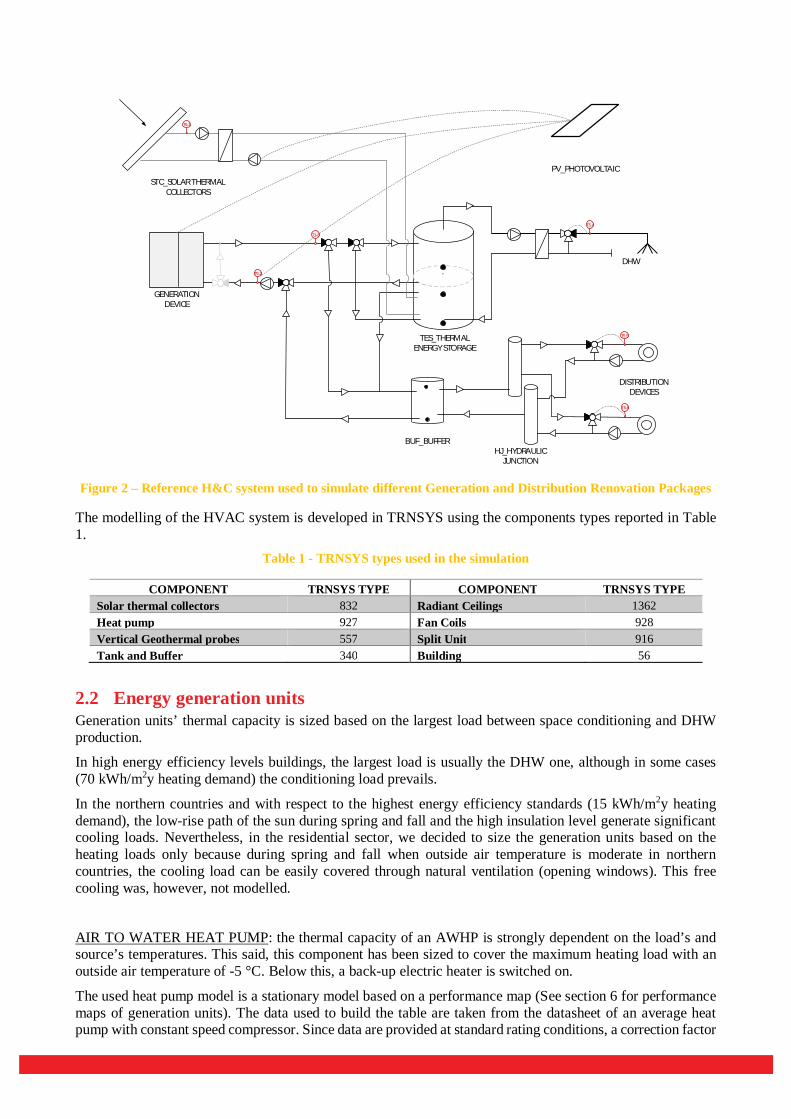
2.1 Layout of the system The reference HVAC system plant layout is composed of a generation system, a distribution system, a storage for DHW, a buffer storage for heating and cooling distribution and solar thermal and photovoltaic systems. This reference structure is the basis for the simulation of different configurations for Single Family Houses (SFH) and Multi Family House (MFH), by varying components sizes and control set points.
The layout has a modular structure in a way that generation and distribution devices as well as components size can be changed without varying the control strategies and the general configuration.
Four generation units have been considered: air to water heat pumps (AWHP), ground source heat pumps (GWHP), biomass and gas boilers (GAS, BIO, see Erreur ! Source du renvoi introuvable.).
The solar thermal field supplies renewable energy into a thermal storage tank in parallel with the main generation unit; depending on the size of the field, the solar energy is used only for DHW preparation (smaller fields compared to the load) or for both heating and DWH preparation (larger fields).
The PV field is used for both driving the generation/distribution systems – namely generation units, pumps, valves and backup heater – and covering the building’s electric appliances. In order to compare the effectiveness of the solar thermal solutions with the PV ones, the PV electricity used to drive the H&C system is treated separately from the one used for the appliances. The excess PV electricity is considered fed into the grid.
With respect to the distribution system, we considered the possible use of radiant ceilings, fan coils and radiators. In the latter case, a split unit is foreseen in addition to the mentioned generation units as the unique source of cooling. Figure 1 summarizes all the generation units and solar technologies combinations.
Figure 1 – Generation renovation packages with solar thermal field (above) and PV panels (below)
Figure 2 shows the layout of the reference H&C system used for all the simulations in TRNSYS.
The generation unit delivers heat and cold to the distribution system, through a small buffer tank: in case of heat pumps, this limits the number of on-off cycles and in winter it can be used for the de-icing phase by reversing the cycle. The size of the buffer tank strongly depends on the generation technology.
Solar heating can be provided to the building by drawing warm water from the solar storage tank when a specific set temperature is exceeded.
A pump + mixing valve unit delivers heat and cold to each thermal zone (floor or dwelling depending on the building) with the needed set temperature and mass flow.
BOILER
STORAGE
STORAGE
STORAGE
STORAGE
STORAGE
A/W HEAT PUMP
A/W HEAT PUMP
W/W HEAT PUMP
W/W HEAT PUMP
STORAGE
BOILER
GENERATION DEVICE
HJ_HYDRAULIC JUNCTION
DHW
BUF_BUFFER
TES_THERMAL ENERGY STORAGE
STC_SOLAR THERMAL COLLECTORS
T5.2
T1.3
T5.4
T5.5
T5.6
T6.1
PV_PHOTOVOLTAIC
DISTRIBUTION DEVICES
Figure 2 – Reference H&C system used to simulate different Generation and Distribution Renovation Packages
The modelling of the HVAC system is developed in TRNSYS using the components types reported in Table 1.
Table 1 - TRNSYS types used in the simulation
COMPONENT TRNSYS TYPE COMPONENT TRNSYS TYPE Solar thermal collectors 832 Radiant Ceilings 1362 Heat pump 927 Fan Coils 928 Vertical Geothermal probes 557 Split Unit 916 Tank and Buffer 340 Building 56
2.2 Energy generation units Generation units’ thermal capacity is sized based on the largest load between space conditioning and DHW production.
In high energy efficiency levels buildings, the largest load is usually the DHW one, although in some cases (70 kWh/m2y heating demand) the conditioning load prevails.
In the northern countries and with respect to the highest energy efficiency standards (15 kWh/m2y heating demand), the low-rise path of the sun during spring and fall and the high insulation level generate significant cooling loads. Nevertheless, in the residential sector, we decided to size the generation units based on the heating loads only because during spring and fall when outside air temperature is moderate in northern countries, the cooling load can be easily covered through natural ventilation (opening windows). This free cooling was, however, not modelled.
AIR TO WATER HEAT PUMP: the thermal capacity of an AWHP is strongly dependent on the load’s and source’s temperatures. This said, this component has been sized to cover the maximum heating load with an outside air temperature of -5 °C. Below this, a back-up electric heater is switched on.
The used heat pump model is a stationary model based on a performance map (See section 6 for performance maps of generation units). The data used to build the table are taken from the datasheet of an average heat pump with constant speed compressor. Since data are provided at standard rating conditions, a correction factor

(1.65) for the size is used to increase both rated thermal capacity and electric consumption to nominal design conditions, being sure that performance at -5 °C are still sufficient to cover the maximum thermal load. The same factor is used for all the climates.
GROUND SOURCE HEAT PUMP: to size the geothermal vertical heat exchanger of ground-source heat pump, average soil properties corresponding to “normal rocky underground” have been assumed for the 7 locations. Following the method and assumption of the norm VDI 4640-2, boreholes length has been calculated as a function of the heat loads to be covered.
The size of the HP is selected accordingly. A correction factor of 1.2 is used also here as a safety factor, accounting that ground temperature ranges around 0 °C in wintertime, therefore temperature at evaporator can drop some degree below this level.
GAS AND BIOMASS BOILERS: condensing gas boiler efficiency is considered dependent on inlet water temperature, while pellet boiler efficiency is considered a constant. Only the case of condensing boiler has been simulated; the pellet boiler consumption are calculated in post process. The efficiency also slightly depends on the partial load ratio (PLR). Correlation between efficiency and inlet temperature and PLR have been retrieved by datasheets.
SPLIT UNITS: For modelling split units, we used the TRNSYS Type 916 “Model for Air Cooled Compression Chillers V0.9” developed by B.Nienborg Frauhofer ISE - directly inspired from the norm DIN V 18599-7. The numerical model gives the set cooling capacity whenever the split unit is on. A nominal EER of 4.5 (at 33 °C ambient temperatures and 26 °C room temperature) is defined according to the common modern split units. A minimum split unit size of 2.5 kW has been chosen as minimum installed cooling capacity (minimum capacity available on the market) per zone.
The split unit model accounts for humidity and thus reduces humidity in the zone; this is reflected in the energy use due to the latent share.
2.3 Solar systems For the installation of the solar thermal and photovoltaic systems, two main variants are considered, as illustrated in the Erreur ! Source du renvoi introuvable.:
On the best-oriented roof (South-West orientation, since the buildings are oriented 45°)
On the South-West façade
With respect to residential buildings, because of the windows and chimneys, the surfaces cannot be completely covered with photovoltaic (PV) modules / solar thermal (ST) collectors. We assume therefore that only 60% of the facade and 80% of the roof surface can be covered.
PHOTOVOLTAIC MODULES: manufacturing data of an average mono-crystalline PV module has been considered for the parameterization and sizing of the PV panels, with an active area of 1.31 m2 per panel. Beside the inclination variants, different number of PV panels have been studied. For the two reference buildings the variants are:
SFH
1 serie of 6 panels (total active area: 7.8 m² - around 1 kWp)
2 series of 6 panels (total active area: 15.6 m²- around 2 kWp)
3 series of 6 panels (total active area: 23.4 m²- around 3 kWp)

MFH – 5 floors
3 series of 6 panels (total active area: 23.6 m² - around 3 kWp)
4 series of 6 panels (total active area: 31.4 m² - around 4 kWp)
5 series of 6 panels (total active area: 39.6 m² - around 5 kWp)
SOLAR THERMAL COLLECTORS: manufacturing data of an average solar thermal collector (eta0 = 0.82, a1 = 3.8) with an active area of 2.3 m2 has been considered for the parameterization and sizing of the solar thermal field. Beside the inclination variants, different number and configuration of solar thermal collectors have been studied:
SFH
1 serie of 2 collectors (total active area: 4.6 m² - only DHW preparation)
1 serie of 4 collectors (total active area: 9.2 m² - DHW preparation and space heating)
2 series of 3 collectors (total active area: 13.8 m² - DHW preparation and space heating)
MFH – 5 floors
2 series of 4 collectors (total active area: 18.4 m² - only DHW preparation)
3 series of 4 collectors (total active area: 27.6 m² - DHW preparation and space heating)
4 series of 4 collectors (total active area: 36.8 m² - DHW preparation and space heating)
2.4 Thermal storages The sizing of the thermal energy storage (TES) respects the requirements for covering the DHW load and for storing solar thermal energy. In case solar thermal collectors are not installed, a minimum storage volume is considered for the DHW uses. Otherwise, the maximum volume is selected among the DHW and solar thermal tank size, the latter being defined as 50 l/m2 or 100 l/m² (litres of the storage tank per surface of the collectors’ area).
2.5 Pipes In the elaborated models, pipes are included in the solar and DHW circuits only. The diameters of each pipe are designed in a way that the water speed never exceeds 1 m/s. The insulation thickness is equal to one diameter for DHW pipelines and to 2 diameters for solar circuit pipes.
2.6 Buffer tank For the air source heat pump, the buffer tank is sized to guarantee the minimum energy required for a de-icing cycle by inverting the compression cycle. This phase is required to avoid the heat pump (HP) performance decreasing due to ice formations on the surface of the evaporator. The buffer tank is sized in order to store the required energy from the HP for the de-icing procedure. The sizing is based on this balance:
퐸 = 퐸
Where the left term is the energy required by the evaporator of the HP at nominal conditions for the de-icing, while the right term is the energy that the buffer can store,
퐸 = 푃 ∗ 푡푖푚푒

The right term can be written also as the evaporator power (Php,ev) for the de-icing duration: a 푡푖푚푒 = 30′ has been considered in this study, as this is a timeframe not affecting the indoor comfort (the heat pump does not deliver heating to the building during de-icing). Consequently, the buffer energy stored during the de-icing is:
퐸 = 푉 ∗ 휌 ∗ 푐 ∗ (푡 − 푡 )
Where 푉 is the volume of the buffer, 휌 is the density of the water contained in the buffer, 푐푝 is the specific heat of the water, 푡 is the set point temperature held in the buffer for supplying the distribution system, and 푡 = 15°퐶, is the minimum temperature acceptable in the buffer.
The buffer tank volume so designed is also useful to reduce the on-off cycles of the heat pump which thermal capacity is most of the times oversized compared to the space heating and cooling thermal loads. Thus, the buffer tank is used also for systems with ground source heat pump.
2.7 Energy distribution systems For the parameterisation and sizing of the different energy distribution systems, manufacturing data and self-made measurements have been considered for a range of units:
RADIANT CEILINGS: a nominal capacity for radiant ceilings of around 140 W/m2 in heating mode and about 100 W/m2 in cooling mode (both at ∆휃 of 10 °C) has been considered.
With an inlet temperature in the panel of 35 °C and a flow rate per panel of 50 kg/hr, the radiant panel capacity is around 140 W/m², while with a temperature of 30 °C the capacity decreases to 93 W/m². In the cooling conditions the panel capacity is around 87 W/m² because of a smaller ∆휃 between the average panel temperature and the ambient. Radiant panels do not dehumidify the air.
The number of radiant panels per zone is consequently calculated in order to cover the building/dwelling peak power.
FAN COILS: the manufacturing data of the vertical 2-tubes fan coil has been considered for the sizing and parameterization of the fan coils model. The fan coil model we refer to is a Carrier 42FA01. Based on the manufacturer data, the performance of this fan coil has been evaluated as a function of the inlet mass flow rate (water side) and the temperature difference between the inlet water and air. Depending on the operating temperatures, the fan coil can cause dehumidification of the air. The used sizing procedure is as follows:
1. A water mass flow rate of 150 kg/h is defined for each fan coil used;
2. As many units are used as the number of the building’s rooms. i.e., in case of a SFH, 3 units per floor are considered, while for MFHs, 5 per dwelling.
3. The total space heating capacity of the units is matched to the building/dwelling peak power by varying the fan coils airflow rate, once the inlet water temperature is decided (35 or 45 °C in the cases considered). The airflow rate of each unit is checked to avoid unreasonable solutions.
This approach is particularly useful since the electric consumption of the fan coils is computed on their airflow rate (45 Wel / kWth). In this way, a link is established between building’s space heating/cooling standard and electricity consumed to cover thermal loads.
RADIATORS: the model “DeLonghi Plantella NT mod. 21” has been selected for the radiator (0.9 meter height, 85 mm width). The performance of this radiator is implemented using the standard logarithmic method. The procedure is as follows:
1. The water mass flow rate is decided based on the model’s performance at specific inlet water

temperatures (35 or 45 °C in the cases considered), in order to install a temperature difference between inlet and outlet of 5 °C.
2. As many units are used as the number of the building’s rooms. i.e., in case of a SFH, 3 units per floor are considered, while for MFHs, 5 per dwelling.
3. The total space heating capacity of the units is matched to the building/dwelling peak power by varying the length of the units. The length of each unit is checked to avoid unreasonable (too long) solutions.
The n-exponent is provided by the manufacturer (n=1.33), while characteristics of radiative and convective fractions come from manuals (Recknagel 2012). The convective part of the emitted heat is supposed to be the 65% of the total, while the radiative is the 35%.

3 HVAC system model for a Wooden Single Family House (WRB)
3.1 Layout of the system The solar cooling system serves for covering all thermal demands of a single family house, having bearing structures in XLAM. The volume of the building is 728 m3, on 2 floors. The building is a single family house, occupied by 4 people and located in Sicily, southern Italy as described in deliverable B1. The layout of the energy plant for DHW, heating and cooling generation is shown in Figure 3: a field of solar thermal collectors (1) is connected to a thermal storage tank (2), supplying the driving energy to the adsorption chiller (4) and, at the same time, producing the domestic hot water (DHW) required. The process heat of the adsorption system is rejected to the environment by using a dry recooler (5), while the chilled water produced is sent to fan coil units (6) for controlling the temperature of the building. A back-up unit is also part of the layout, consisting in a methane boiler (3) that is commonly present in European houses and has been consequently preferred to an electric chiller back-up.
Figure 3 - layout of the air conditioning system of the WRB.
The types used for the simulation of the system in TRNSYS are summarised in Table 2. Table 2 - TRNSYS types used in the simulation
COMPONENT TRNSYS TYPE COMPONENT TRNSYS TYPE Solar thermal collectors 71 Pumps 3b Heater 751 Meteorological data 15-2 Storage tank 60f Sky temperature 69b Adsorption chiller 909 Psychometrics calculations 33e Fan coil 508h Daily schedules 14h Recooler 511
3.2 Solar collectors The solar collectors field is made up of compound parabolic collectors (CPC), each with an aperture area of 4.40 m2 and 30 evacuated tubes. They are used not only for DHW production, but also for space heating during winter and for driving the adsorption chiller during summer. The number of solar collectors chosen varies from 6 to 10, with 2 collectors step.
3.3 Storage tank The storage tank is a hot water sensible tank with 1 m3 volume. It is equipped with two internal coils, having exchange areas of 3.5 m2 and 1.8 m2, according to the specification of a commercial unit (Cordivari Bolly 2 ST1). They have been used for the connection of the solar loop and for the production of DHW, respectively.
3.4 Adsorption chiller The adsorption chiller has been simulated using type 909, which embeds a parametric performance map of power and COP. Such a performance map has been realised starting from the measurement done at ITAE of a commercial silica gel/water unit, with nominal power of 10 kW and 0.65 nominal COP. The performance curves are reported in par. 7.
3.5 Dry recooler The used dry fluid cooler is based on TRNSYS type 511, in which the design conditions (flow rates and temperature) are inserted as parameters, together with the desired outlet temperature. The model, first uses design data to determine the UA of the heat exchanger at design conditions, then corrects design UA according to instant inlet conditions and finally calculates the air flow rate required in order for the dry fluid cooler to deliver the specified outlet liquid temperature. The features of the simulated re-cooler, based on the specifications of a commercial unit (Fahrenheit eRec 10), are reported in Table 3.
Table 3 - Parameters used in the simulated recooler.
Parameter Unit Value Design inlet fluid temperature °C 30.6
Design outlet fluid temperature °C 25 Design fluid flow rate kg/h 25000 Design air flow rate kg/h 400000
Rated fan power kW 5.4
1 http://www.cordivari.it/Bollitori_Solari/Bollitori/bolly_2_st

4 HVAC system model for a Single Family House - TheBat building
The HVAC system in this model is used to cover heating load as well as DHW load, based on the demands of the reference building as described in deliverable B1.
The configuration of the system is shown in Figure 4. It is composed of a generation system (HP), a thermal energy storage for DHW and heating support (TES), the distribution system for space heating (SH) and DHW and a PV system. Several different configurations have been simulated for different sizing parameters and control strategies.
The energy generation unit consists of a ground source brine heat pump. No additional heat generation units were considered.
The PV field is used to supply electricity for the generation unit. In order to be able to analyse the effectiveness of the PV system based on different configurations, energy produced by PV and directly used by the heat pump is considered separately. The excess PV electricity is considered fed into the grid.
Figure 4 - Hydraulic concept of the heat pump system in connection to TES and building
4.1 Energy generation unit Based on the location and purpose of the building, only DHW and space heating needs must be satisfied by the energy generation system.
For this model, only a ground source heat pump was considered as a generation unit. The units’ thermal capacity is sized based on the chosen product of the project partner and on the calculated loads. As can be seen in Figure 4, the heat pump is equipped with a desuperheater which allows heating of the topmost TES-volume independently of the used cycle for the condenser outlet.
For the ground source heat exchanger, average soul temperatures have been calculated based on the Kasuda-model for the temperature in a depth of 2 m.

4.2 Solar Energy System For solar technologies, only the combination with a photovoltaic system was considered. The reference building is NS-oriented. Based on this the installation of the photovoltaic system was only considered on the southern facing roof area at an inclination of 40°.
Two different variants were considered based on the PV area:
- 20 m² which equals ~2.5 kWp - 40 m² which equals ~5.0 kWp
4.3 Thermal storage The thermal energy storage is used to supply energy for the DHW load as well as for space heating.
The size of the TES is one of the sizing parameters which were used in the different configurations of the system. Based on that, three different TES-sizes were considered in the model:
- 500 L
o Radius 0.30 m
o Height 1.80 m
o U-Value 1.44 kJ/h.m².K
- 1000 L
o Radius 0.40 m
o Height 2.00 m
o U-Value 0.88 kJ/h.m².K
- 2000 L
o Radius 0.55 m
o Height 2.10 m
o U-Value 0.68 kJ/h.m².K
All tanks include an additional 0.10 m of dead volume at the bottom. Of those sizes, the top 300 L are considered as supply for the DHW load. The remaining volume is considered energy storage for space heating. In several of the configurations, control strategies are considered in which overheating of the TES with PV-energy is implemented.
4.4 Pipes In the model for modelling thermal losses and for ensuring the system stability, pipes are included:
- on the source side of the heat pump; - from the energy supply unit to the TES; - from the TES to the energy distribution system; - on a bypass of the TES to directly supply from the heat pump to the energy distribution system.
All pipes are considered with a heat loss coefficient of 2.88 kJ/hr.m².K. The diameters of each pipe are designed in a way that the water speed never exceeds 1 m/s.
4.5 Energy distribution system In this model, the distribution system consists of a floor heating system fed by the thermal energy storage as well as directly from the energy generation unit.
The nominal capacity of the energy distribution system in heating mode is around 71 W/m². This value can temporarily be surpassed if the TES is used as a source for the space heating system.
For DHW-preparation, a separate cycle exists between the TES and a heat exchanger. The control strategies of the variable speed pump as well as the temperature targets in the TES guarantee that sufficient energy for DHW-preparation is supplied to the heat exchanger.
In the case of several control strategies, space heating thermal power has been used for sizing purposes. This happens by changing the setpoint of the room temperature as was mentioned in deliverable B1.
A detailed description of the control concepts can be found in deliverable B5.
5 HVAC system model for a Reference Multi Family House from the Project HVACviaFaçade
In the Austrian national project HVACviaFaçade [2], system concepts for space heating, domestic hot water and ventilation for multi-family buildings have been developed where as many components as possible can be integrated in a new building façade. The goal was to reduce system costs and to avoid that inhabitants have to move out of their apartments during the renovation of the building.
Three different system concepts were analyzed in detail:
A central system with an outdoor air heat pump;
Distributed systems with a separate outdoor air heat pump for each apartment;
Distributed systems with direct electrical heating elements in each apartment.
All system concepts were simulated for two different energy levels (15 and 30 kWh/(m² a) of space heating demand). In case of the energy level 15 building, a controlled ventilation system with heat recovery was assumed whereas the energy level 30 building included only an exhaust air system with air inlets built into the window frames.
More details on the systems can be found in German language in [2].
5.1 Central Outdoor Air Heat Pump The first system concept includes a central exhaust air heat pump which heats a central buffer tank. From the buffer tank, the heat is distributed to the radiators and to a domestic hot water tank in each apartment. The domestic hot water tanks are charged only during two time windows per day so that the heat pump does not operate at high temperature during the whole day. The system concept for the two building energy levels is shown in Figure 5.
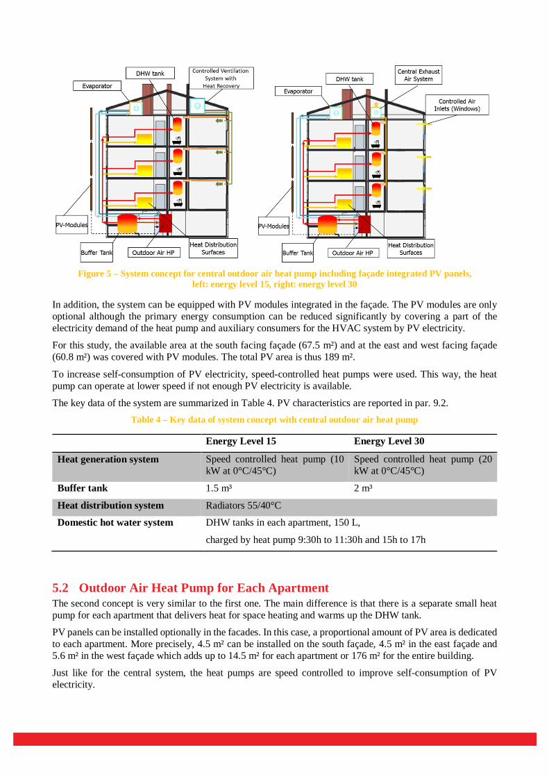
Figure 5 – System concept for central outdoor air heat pump including façade integrated PV panels,
left: energy level 15, right: energy level 30
In addition, the system can be equipped with PV modules integrated in the façade. The PV modules are only optional although the primary energy consumption can be reduced significantly by covering a part of the electricity demand of the heat pump and auxiliary consumers for the HVAC system by PV electricity.
For this study, the available area at the south facing façade (67.5 m²) and at the east and west facing façade (60.8 m²) was covered with PV modules. The total PV area is thus 189 m².
To increase self-consumption of PV electricity, speed-controlled heat pumps were used. This way, the heat pump can operate at lower speed if not enough PV electricity is available.
The key data of the system are summarized in Table 4. PV characteristics are reported in par. 9.2. Table 4 – Key data of system concept with central outdoor air heat pump
Energy Level 15 Energy Level 30
Heat generation system Speed controlled heat pump (10 kW at 0°C/45°C)
Speed controlled heat pump (20 kW at 0°C/45°C)
Buffer tank 1.5 m³ 2 m³
Heat distribution system Radiators 55/40°C
Domestic hot water system DHW tanks in each apartment, 150 L,
charged by heat pump 9:30h to 11:30h and 15h to 17h
5.2 Outdoor Air Heat Pump for Each Apartment The second concept is very similar to the first one. The main difference is that there is a separate small heat pump for each apartment that delivers heat for space heating and warms up the DHW tank.
PV panels can be installed optionally in the facades. In this case, a proportional amount of PV area is dedicated to each apartment. More precisely, 4.5 m² can be installed on the south façade, 4.5 m² in the east façade and 5.6 m² in the west façade which adds up to 14.5 m² for each apartment or 176 m² for the entire building.
Just like for the central system, the heat pumps are speed controlled to improve self-consumption of PV electricity.

Figure 6 - System concept for separate outdoor air heat pumps for each apartment including façade integrated PV panels, left: energy level 15, right: energy level 30
The key data of the system concept are summarized in Table 5. Table 5 – Key data of system concept with separate outdoor air heat pump for each apartment
Energy Level 15 and 30
Heat generation system Speed controlled heat pump (2 kW at 0°C/45°C)
Buffer tank none
Heat distribution system Radiators 55/40°C
Domestic hot water system DHW tanks in each apartment, 150 L, charged by heat pump 9:30h to 11:30h and 15h to 17h
An experimental model of a façade element that includes the small-scale heat pump, a duct system where all piping can be included and a PV panel, has been designed and built (see Figure 7). The small-scale heat pump was developed and built by the company Vaillant GmbH who was partner in the project. The heat pump was built into the duct system next to the window in a way that it can be accessed for maintenance from the window reveal. A small façade panel next to the window can be removed and then the heat pump can be pulled out on a base plate mounted on a track system. The façade element was constructed by the company Kulmer Holz-Leimbau GmbH, another project partner.

Figure 7 – Experimental model of a façade element with vertical duct where vertical piping and a small-scale heat pump are integrated (left), small-scale heat pump for façade integration (right), picture source: Kulmer
Holz-Leimbau GmbH (left) and Vaillant GmbH (right)
5.3 Direct Electrical Heating In the third concept, both space heating and DHW demand are covered directly from electricity. For space heating, there are infrared panels installed in the apartments. In addition, each apartment has an electric water heater with 150 L volume.
For comparison reasons, this concept was also calculated without PV system. However, from the point of view of primary energy consumption the system only makes sense with large PV areas. Again for comparison reasons, the concept was considered having the same PV areas as the system with separate heat pumps in each apartment. As a third case, the entire surface area available on the reference building was used to install PV panels. This includes also east and west roof area with a slope of 20°. Altogether this adds up to 34.9 m² for each apartment or 419 m² for the entire building.
Figure 8 - System concept for direct electrical heating including façade integrated PV panels, left: energy level 15, right: energy level 30
The key data of the system concept are summarized in Table 6.

Table 6 – Key data of system concept with direct electrical heating
Energy Level 15 and 30
Heat generation system Electricity from PV panels or from the grid
Buffer tank none
Heat distribution system Infrared panels
Domestic hot water system DHW tanks in each apartment, 150 L, 2500 W electrical heating element
5.4 TRNSYS Components Used for Simulation Study
All simulations for this study have been carried out in the simulation environment TRNSYS 17. The following table summarizes the models that were used for the main components of the systems.
Table 7 – TRNSYS Components used for the simulation study
COMPONENT TRNSYS TYPE COMPONENT TRNSYS TYPE
Speed Controlled Heat Pump 977 DHW Tank 4a
PV 94a Building 56
Inverter 48a Ground Temperature 77
Buffer Tank 340

6 Annex I – Performance of the HVAC components used for the iNSPiRe project reference buildings
This Annex summarizes the performance figures for all generation units. Data are obtained from manufacturers’ datasheets.
6.1 Air to Water heat pump Figure 9 shows how COP varies according to ambient temperature and temperature at the condenser, while Figure 10 shows EER trends in relation to external air temperature and temperature at the evaporator.
Figure 9 - Coefficient Of Performance for an Air to Water Heat Pump in winter mode as a function of the
ambient air and the inlet water temperature at the condensing side
Figure 10 - Energy Efficiency Ratio for the Air to Water Heat Pump in cooling mode as a function of the ambient air and the inlet water temperature at evaporator side
6.2 Ground Source heat pump Figure 11 shows the COP variation at different evaporator and condensing temperatures, whereas Figure 12 draws the EER trends depending, again, on the evaporator and condensing temperatures.
0
1
2
3
4
5
6
-10 -8 -6 -4 -2 0 2 4 6 8 10 12 14 16 18 20
Coe
ffici
ent O
f Per
form
ance
, CO
P [-]
Air temperature, Tair_in [°C]
COP Tcond.20 COP Tcond.25 COP Tcond.30 COP Tcond.35
COP Tcond.40 COP Tcond.45 COP Tcond.50
0
1
2
3
4
5
6
7
15 17 19 21 23 25 27 29 31 33 35 37 39 41 43 45
Ener
gy E
ffici
ency
Rat
io, E
ER[-]
Air temperature, Tair_in [°C]
EER Tevap. 12 EER Tevap. 14 EER Tevap. 16 EER Tevap. 18
EER Tevap. 20 EER Tevap. 22 EER Tevap. 24
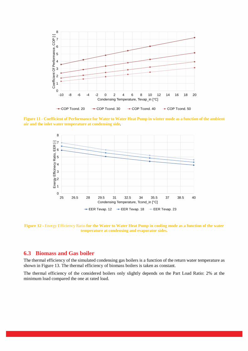
Figure 11 - Coefficient of Performance for Water to Water Heat Pump in winter mode as a function of the ambient air and the inlet water temperature at condensing side.
Figure 12 - Energy Efficiency Ratio for the Water to Water Heat Pump in cooling mode as a function of the water temperature at condensing and evaporator sides.
6.3 Biomass and Gas boiler The thermal efficiency of the simulated condensing gas boilers is a function of the return water temperature as shown in Figure 13. The thermal efficiency of biomass boilers is taken as constant.
The thermal efficiency of the considered boilers only slightly depends on the Part Load Ratio: 2% at the minimum load compared the one at rated load.
0
1
2
3
4
5
6
7
8
-10 -8 -6 -4 -2 0 2 4 6 8 10 12 14 16 18 20
Coe
ffici
ent O
f Per
form
ance
, CO
P [-]
Condensing Temperature, Tevap_in [°C]
COP Tcond. 20 COP Tcond. 30 COP Tcond. 40 COP Tcond. 50
0
1
2
3
4
5
6
7
8
25 26.5 28 29.5 31 32.5 34 35.5 37 38.5 40
Ener
gy E
ffici
necy
Rat
io, E
ER [-
]
Condensing Temperature, Tcond_in [°C]
EER Tevap. 12 EER Tevap. 18 EER Tevap. 23

Figure 13 – Efficiency of the condensing boiler as a function of the return temperature of the water.
6.4 PV panels The PV production has been calculated using crystalline panels which main characteristics are reported in the following table.
Table 8 – Main characteristics of the PV panels
UNIT VALUE
Nominal power [Wp] 220
Electric efficiency (at rated conditions) % 13
Voltage at maximum-power point [V] 36
Current at maximum-power point [A] 4,58
Voltage at open circuit [V] 43,8
Current at short circuit [A] 5,18
6.5 Solar thermal collectors For the study, solar collectors, which main characteristics are reported in the following table, are used:
Table 9 - Main characteristics of the ST collectors
UNIT VALUE
Collector surface [m²] 2.3
Efficiency [%] 82,4
Coefficient of heat loss – k1 [W/(m²K)] 3,792
Coefficient of heat loss – k2 [W/(m²K)] 0,021
The mass flow rate for the solar thermal field has been calculated considering a value of 50 kg/h per m2 of panel; actually it consists of 115 kg/h for each series of collectors.
0.94
0.96
0.98
1
1.02
1.04
1.06
1.08
20 25 30 35 40 45 50 55 60 65 70
Effic
ienc
y, η
[-]
Return temperature, Tret. [°C]

6.6 Split Unit The design EER of the Split unit (air to air heat pump) is 4.5, as a common value of split units on the market. The EER is function of the ambient temperature and the standard conditions are referred to 31°C ambient (see Figure 14).
Figure 14 - Energy Efficiency Ratio for the Air to Air Heat Pump in cooling mode as a function of the ambient air temperature.
2.0
2.5
3.0
3.5
4.0
4.5
5.0
5.5
6.0
6.5
20 22 24 26 28 30 32 34 36 38 40
Ener
gy E
ffici
ency
Rat
io, E
ER [-
]
Air Temperature, Tair_in [°C]
7 ANNEX II - Performance of the HVAC components used in the WRB models
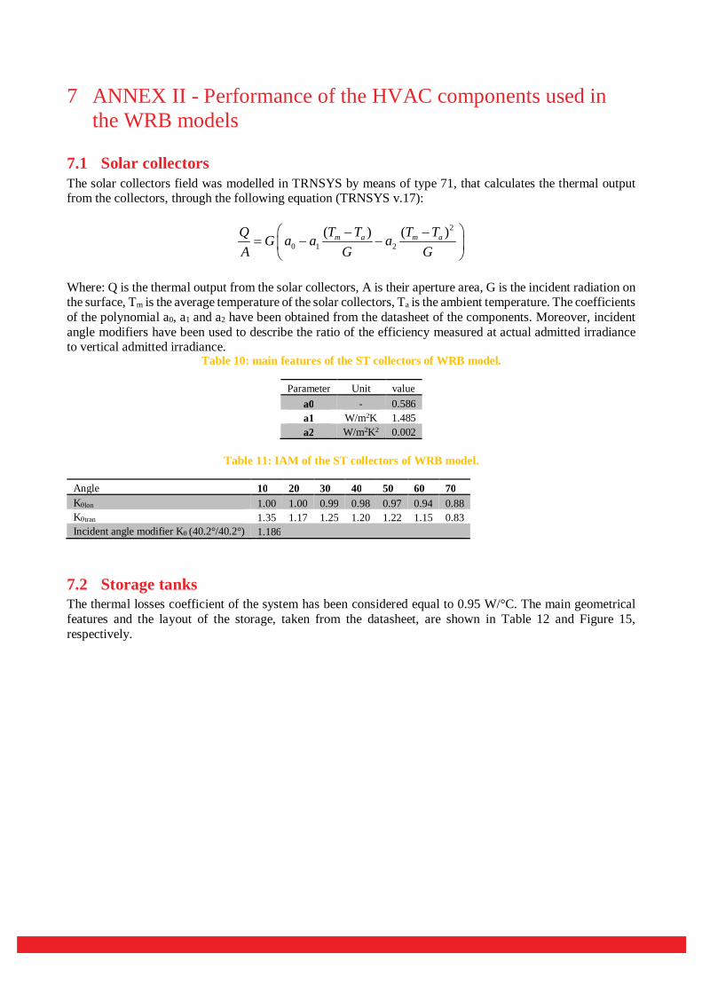
7.1 Solar collectors The solar collectors field was modelled in TRNSYS by means of type 71, that calculates the thermal output from the collectors, through the following equation (TRNSYS v.17):
2
0 1 2( ) ( )m a m aT T T TQ G a a a
A G G
Where: Q is the thermal output from the solar collectors, A is their aperture area, G is the incident radiation on the surface, Tm is the average temperature of the solar collectors, Ta is the ambient temperature. The coefficients of the polynomial a0, a1 and a2 have been obtained from the datasheet of the components. Moreover, incident angle modifiers have been used to describe the ratio of the efficiency measured at actual admitted irradiance to vertical admitted irradiance.
Table 10: main features of the ST collectors of WRB model.
Parameter Unit value a0 - 0.586 a1 W/m2K 1.485 a2 W/m2K2 0.002
Table 11: IAM of the ST collectors of WRB model.
Angle 10 20 30 40 50 60 70 Klon 1.00 1.00 0.99 0.98 0.97 0.94 0.88 Ktran 1.35 1.17 1.25 1.20 1.22 1.15 0.83 Incident angle modifier K (40.2°/40.2°) 1.186
7.2 Storage tanks The thermal losses coefficient of the system has been considered equal to 0.95 W/°C. The main geometrical features and the layout of the storage, taken from the datasheet, are shown in Table 12 and Figure 15, respectively.

Figure 15 -layout of the storage tank in the WRB model, taken from the datasheet of the producer
Table 12 - main geometrical features of the storage tank in the WRB model.
De Df H A H3 H4 H6 H9 H12 mm mm mm mm mm mm mm mm mm 1050 850 2217 2432 439 499 1279 1399 1819
7.3 Adsorption chiller
The adsorption chiller adopted is a commercial 10 kW silica gel/water unit. The system was characterized at CNR ITAE by means of a dedicated testing rig. In particular, tests under different boundary conditions (in terms of driving temperature, condensation temperature and evaporation temperature) were carried out. The results, reported in Figure 16 and Figure 17 show the cooling power and the thermal COP of the chiller under the different boundaries. All the data refer to chilled water temperature set-point of 16°C.

Figure 16 - Cooling power of the commercial chiller at variable heat rejection and driving temperatures
Figure 17 - COP of the commercial chiller at variable heat rejection and driving temperatures

8 ANNEX III - Performance of the HVAC components used for the Single Family House – TheBat building
9 ANNEX IV - Performance of the HVAC components used for the Multi Family House reference Building from Project HVACviaFaçade
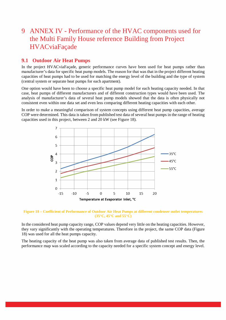
9.1 Outdoor Air Heat Pumps In the project HVACviaFaçade, generic performance curves have been used for heat pumps rather than manufacturer’s data for specific heat pump models. The reason for that was that in the project different heating capacities of heat pumps had to be used for matching the energy level of the building and the type of system (central system or separate heat pumps for each apartment).
One option would have been to choose a specific heat pump model for each heating capacity needed. In that case, heat pumps of different manufacturers and of different construction types would have been used. The analysis of manufacturer’s data of several heat pump models showed that the data is often physically not consistent even within one data set and even less comparing different heating capacities with each other.
In order to make a meaningful comparison of system concepts using different heat pump capacities, average COP were determined. This data is taken from published test data of several heat pumps in the range of heating capacities used in this project, between 2 and 20 kW (see Figure 18).
Figure 18 – Coefficient of Performance of Outdoor Air Heat Pumps at different condenser outlet temperatures (35°C, 45°C and 55°C)
In the considered heat pump capacity range, COP values depend very little on the heating capacities. However, they vary significantly with the operating temperatures. Therefore in the project, the same COP data (Figure 18) was used for all the heat pumps capacity.
The heating capacity of the heat pump was also taken from average data of published test results. Then, the performance map was scaled according to the capacity needed for a specific system concept and energy level.

Figure 19 – Performance Map of an outdoor air heat pump at different condenser outlet temperatures (35°C,
45°C and 55°C), heating capacity of 2 kW at 0°C evaporator inlet temperature and 45°C condenser outlet temperature
Figure 20 – Performance Map of at outdoor air heat pump at different condenser outlet temperatures (35°C,
45°C and 55°C), heating capacity of 10 kW and 20 kW at 0°C evaporator inlet temperature and 45°C condenser outlet temperature

9.2 Photovoltaics
The main characteristics of the used PV panels are shown in the following table. Table 13 – Main characteristics of the PV panels
VALUE UNIT
Nominal power 165 [Wp]
Surface area 1.125 [m²]
Electric efficiency (at rated conditions) 13 %
Voltage at maximum-power point 36 [V]
Current at maximum-power point 4.58 [A]
Voltage at open circuit 43.8 [V]
Current at short circuit 5.18 [A]

10 Literature references 1. iNSPiRe project, Grant Agreement n° 314461 2013-2017 www.inspirefp7.eu
2. Christian Fink et al. Final Project Report: Vorgefertigte Fassadenelemente mit maximal integrierten HVAC-Komponenten und –Systemen zur Bestandssanierung (in German), Austrian Klima- und Energiefond, Project number: 843945, 2017
Note : the IEA SHC Technology Collaboration Programme (IEA SHC TCP) functions within a framework created by the International Energy Agency (IEA). Views, findings and publications of the IEA SHC TCP do not necessarily represent the views or policies of the IEA Secretariat or of its individual member countries. The IEA SHC TCP and the IEA make no representation or warranty, express or implied, in respect of this paper’s content (including its completeness or accuracy) and shall not be responsible for any use of, or reliance on, the paper.