Summary - Energy Design Resources · Central DHW Systems in Multifamily Buildings design brief...
13
Central DHW Systems in Multifamily Buildings design brief Summary Domestic water heating (DHW) accounts for a significant share of multifamily building energy use, especially in California’s coastal towns. While each new construction project will have a different ratio of energy end uses, one can look at the existing building stock to get an idea of how much is attributable to DHW systems. According to the Department of Energy’s Residential Energy Consumption Survey (RECS), DHW accounted for around 32% of overall energy use for existing multifamily units in the late 1990’s. 1 DHW can be installed on a unit-by-unit level through individual water heaters or a building-wide basis using a single water heating device, such as a boiler, to provide hot water for multiple dwelling units. This second category is known as a central DHW system. The following design guide, intended for building owners, developers, and designers, provides an overview and introduction to central DHW systems by: 1. Highlighting the basics of the regulatory context in California (Title 24) 2. Discussing the major opportunities for energy savings and improved service to tenants through improved systems, many of which have arisen from recent advances in heater and boiler technology and advanced control systems 3. Identifying common design problems and mistakes 1 O’Brien, Eileen M., comp. United States. Energy Information Administration. Department of Energy. Residential Energy Consumption Survey. Nov. 1999. 2 July 2008 http://www.eia.doe.gov/emeu/recs. Central DHW Heater Options 2 Instantaneous (Tankless) vs. Storage Tank 2 Condensing vs. Non-Condensing 3 Performance Specifications 4 Central DHW Recirculation Loops 5 Recirculation Loop Controls 8 Commissioning, Performance Monitoring, Fault Detection and Diagnosis 10 Code Provisions Set Baseline for Energy Performance 11 Mandatory Requirements 11 Prescriptive Requirements 12 Performance Requirements 12 Resources for Designers and Contractors 13 contents
-
Upload
nguyenhanh -
Category
Documents
-
view
219 -
download
4
Transcript of Summary - Energy Design Resources · Central DHW Systems in Multifamily Buildings design brief...
Central DHW Systems in Multifamily Buildings
design brief
Summary
Domestic water heating (DHW) accounts for a significant share of
multifamily building energy use, especially in California’s coastal
towns. While each new construction project will have a different ratio
of energy end uses, one can look at the existing building stock to get
an idea of how much is attributable to DHW systems. According to
the Department of Energy’s Residential Energy Consumption Survey
(RECS), DHW accounted for around 32% of overall energy use for
existing multifamily units in the late 1990’s.1
DHW can be installed on a unit-by-unit level through individual water
heaters or a building-wide basis using a single water heating device,
such as a boiler, to provide hot water for multiple dwelling units. This
second category is known as a central DHW system.
The following design guide, intended for building owners, developers,
and designers, provides an overview and introduction to central DHW
systems by:
1. Highlighting the basics of the regulatory context in California
(Title 24)
2. Discussing the major opportunities for energy savings and
improved service to tenants through improved systems, many
of which have arisen from recent advances in heater and boiler
technology and advanced control systems
3. Identifying common design problems and mistakes
1 O’Brien, Eileen M., comp. United States. Energy Information Administration. Department of Energy. Residential Energy Consumption Survey. Nov. 1999. 2 July 2008 http://www.eia.doe.gov/emeu/recs.
Central DHW Heater Options 2
Instantaneous (Tankless) vs. Storage Tank 2
Condensing vs. Non-Condensing 3
Performance Specifications 4
Central DHW Recirculation Loops 5
Recirculation Loop Controls 8
Commissioning, Performance Monitoring, Fault Detection and Diagnosis 10
Code Provisions Set Baseline for Energy Performance 11
Mandatory Requirements 11
Prescriptive Requirements 12
Performance Requirements 12
Resources for Designers and Contractors 13
contents
PAGE 2 Design Brief on Central DHW Systems in Multifamily Buildings
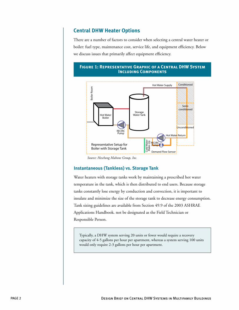
Central DHW Heater Options
There are a number of factors to consider when selecting a central water heater or
boiler: fuel type, maintenance cost, service life, and equipment efficiency. Below
we discuss issues that primarily affect equipment efficiency.
Typically, a DHW system serving 20 units or fewer would require a recovery capacity of 4-5 gallons per hour per apartment, whereas a system serving 100 units would only require 2-3 gallons per hour per apartment.
Figure 1: Representative Graphic of a Central DHW System Including Components
Hot WaterBoiler
RECIRCPump
RECIRCPump
Cold
Wat
erM
ake-
Up
Boile
r Roo
m
Demand Flow Sensor
Representative Setup forBoiler with Storage Tank
StorageWater Tank
Hot Water Supply
Hot Water Return
Conditioned
Semi-conditioned
Unconditioned
Source: Heschong Mahone Group, Inc.
Instantaneous (Tankless) vs. Storage Tank
Water heaters with storage tanks work by maintaining a prescribed hot water
temperature in the tank, which is then distributed to end users. Because storage
tanks constantly lose energy by conduction and convection, it is important to
insulate and minimize the size of the storage tank to decrease energy consumption.
Tank sizing guidelines are available from Section 49.9 of the 2003 ASHRAE
Applications Handbook. not be designated as the Field Technician or
Responsible Person.
PAGE 3Design Brief on Central DHW Systems in Multifamily Buildings
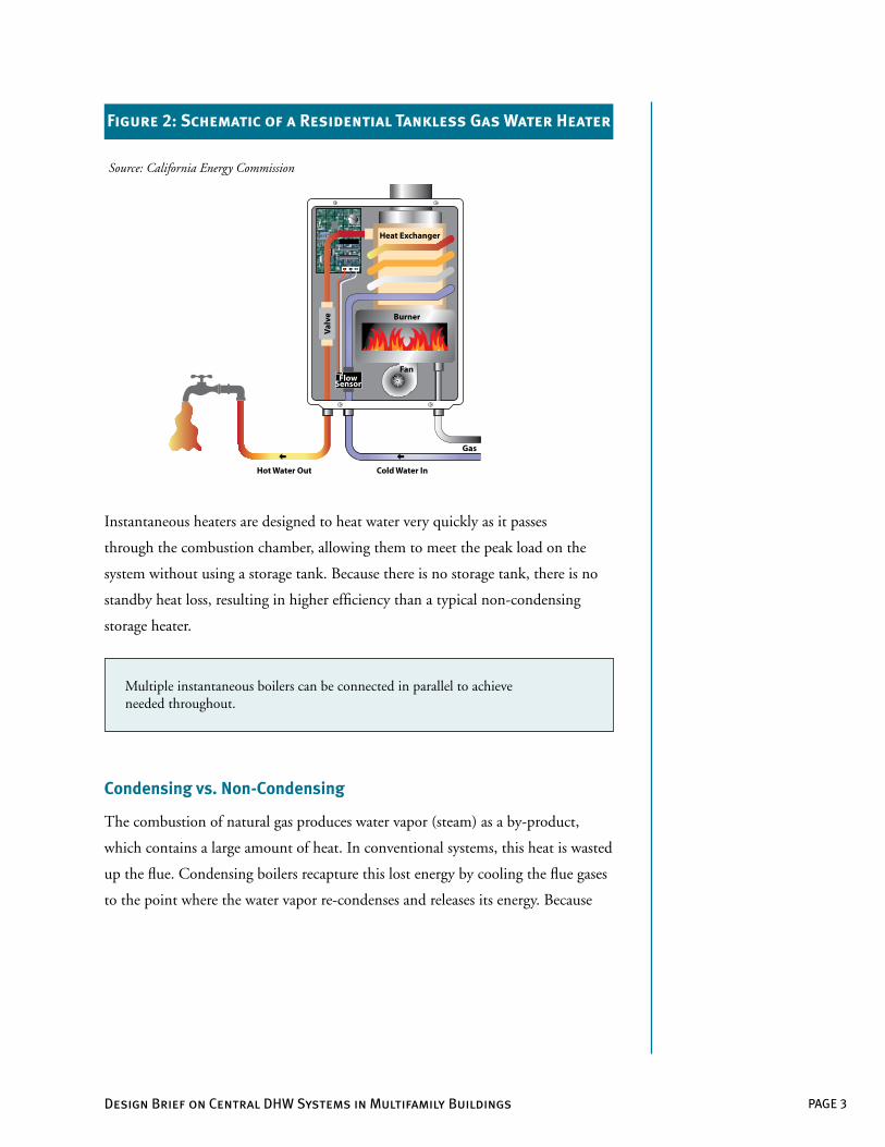
Instantaneous heaters are designed to heat water very quickly as it passes
through the combustion chamber, allowing them to meet the peak load on the
system without using a storage tank. Because there is no storage tank, there is no
standby heat loss, resulting in higher efficiency than a typical non-condensing
storage heater.
Figure 2: Schematic of a Residential Tankless Gas Water Heater
Source: California Energy Commission
Fan
Gas
Cold Water InHot Water Out
BurnerVa
lve
Heat Exchanger
FlowSensor
Multiple instantaneous boilers can be connected in parallel to achieve needed throughout.
Condensing vs. Non-Condensing
The combustion of natural gas produces water vapor (steam) as a by-product,
which contains a large amount of heat. In conventional systems, this heat is wasted
up the flue. Condensing boilers recapture this lost energy by cooling the flue gases
to the point where the water vapor re-condenses and releases its energy. Because
PAGE 4 Design Brief on Central DHW Systems in Multifamily Buildings
Additionally, condensing boilers, unlike conventional heaters, are particularly
efficient from a cold start or under part load, which are common operating
conditions for service water heating. These systems are now required by law in
many European countries and are increasingly popular in the U.S.
Performance Specifications
Small capacity water heaters (75,000 Btu per hour or less for gas water heaters)
are described by an energy factor (EF) - the higher the energy factor, the more
efficient the water heater. The EF indicates a water heater’s overall energy
1 This increased efficiency occurs because the standard calorific value attributed to natural gas includes a downward adjustment equal to the latent heat of the steam.
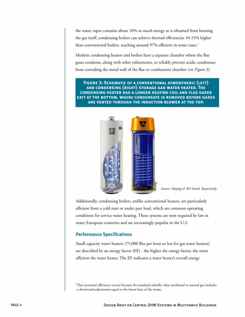
Figure 3: Schematic of a conventional atmospheric (left) and condensing (right) storage gas water heater. The
condensing heater has a longer heating coil and flue gases exit at the bottom, where condensate is removed before gases
are vented through the induction blower at the top.
Source: Maytag & AO Smith, Respectively
the water vapor contains about 10% as much energy as is obtained from burning
the gas itself, condensing boilers can achieve thermal efficiencies 10-15% higher
than conventional boilers, reaching around 97% efficient in some cases.1
Modern condensing heaters and boilers have a separate chamber where the flue
gases condense, along with other refinements, to reliably prevent acidic condensate
from corroding the metal wall of the flue or combustion chamber (see Figure 3).
PAGE 5Design Brief on Central DHW Systems in Multifamily Buildings
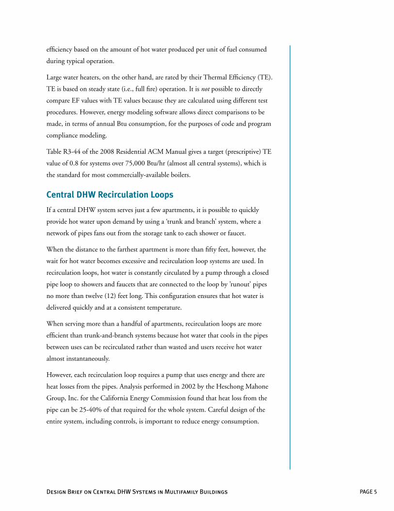
efficiency based on the amount of hot water produced per unit of fuel consumed
during typical operation.
Large water heaters, on the other hand, are rated by their Thermal Efficiency (TE).
TE is based on steady state (i.e., full fire) operation. It is not possible to directly
compare EF values with TE values because they are calculated using different test
procedures. However, energy modeling software allows direct comparisons to be
made, in terms of annual Btu consumption, for the purposes of code and program
compliance modeling.
Table R3-44 of the 2008 Residential ACM Manual gives a target (prescriptive) TE
value of 0.8 for systems over 75,000 Btu/hr (almost all central systems), which is
the standard for most commercially-available boilers.
Central DHW Recirculation Loops
If a central DHW system serves just a few apartments, it is possible to quickly
provide hot water upon demand by using a ‘trunk and branch’ system, where a
network of pipes fans out from the storage tank to each shower or faucet.
When the distance to the farthest apartment is more than fifty feet, however, the
wait for hot water becomes excessive and recirculation loop systems are used. In
recirculation loops, hot water is constantly circulated by a pump through a closed
pipe loop to showers and faucets that are connected to the loop by ’runout’ pipes
no more than twelve (12) feet long. This configuration ensures that hot water is
delivered quickly and at a consistent temperature.
When serving more than a handful of apartments, recirculation loops are more
efficient than trunk-and-branch systems because hot water that cools in the pipes
between uses can be recirculated rather than wasted and users receive hot water
almost instantaneously.
However, each recirculation loop requires a pump that uses energy and there are
heat losses from the pipes. Analysis performed in 2002 by the Heschong Mahone
Group, Inc. for the California Energy Commission found that heat loss from the
pipe can be 25-40% of that required for the whole system. Careful design of the
entire system, including controls, is important to reduce energy consumption.
PAGE 6 Design Brief on Central DHW Systems in Multifamily Buildings
There are many different ways to design a recirculation loop system. All of the
following factors can be chosen to minimize energy use and provide the highest
level of service for tenants.
n Number of heaters or boilers: Larger heaters may be more efficient and
cost-effective than smaller heaters, but having two or more small heaters per
loop provides redundancy so that tenants still receive hot water if a unit fails
or is taken off line for maintenance.
n Routing and insulation: Recirculation loops should be as short as possible
while minimizing runout lengths and routed close to conditioned space to
reduce energy loss to the outside. Pipes laid underground or attached to the
side of the building are highly inefficient, although energy loss can be reduced
somewhat by adding insulation that is completely protected from water ingress.
Horizontal recirculation loops are usually the best choice because they
minimize pressure differentials and the potential for stratification. A single
horizontal loop can serve up to three stories via additional vertical legs.
n Bends: Using gradual bends instead of ‘hard ninety’ elbows allows water
to flow faster and more smoothly, with reduced heat losses and friction.
Consequently, the hot water supply temperature and pump size can be
reduced for increased savings. Gradual bends also reduce the chance of
pinhole leaks from pipe wall erosion.
n Pump sizing: Correct pump sizing is important both for energy
consumption and the quality of service provided to tenants. Generally, large
pumps are required to serve demand-controlled systems, since the whole loop
must be primed with hot water. Smaller pumps are sufficient for timeclock or
temperature modulation controls, which circulate the water continuously.
For demand systems, size the pump to provide hot water to the last tenant
on the loop within a reasonable time frame. To approximately calculate the
time delay, divide the volume of water in the loop by the flow rate through
the pump.
PAGE 7Design Brief on Central DHW Systems in Multifamily Buildings
Designers should be careful not to specify a pump that’s more powerful than required, since this will increase the electricity use of the system, increase the rate of crossover flow, and create faster and more turbulent flows that erode the pipe more quickly, leading to leaks
For continuously circulating systems, flow rates should be lower to reduce
erosion corrosion at elbows and bends. However, very low flow rates can allow
debris to settle in the pipe and can increase the required supply temperature.
Flow rates between one and one half (1½) and three and one half (3½) feet
per second provide a reasonable trade-off.
n Runouts: Usually, all hot water in a runout is wasted because it cools before
the next use of the outlet and must be drained before useable hot water is
received. A twelve (12) foot long, three-quarter (¾) inch wide runout contains
over two (2) pints of water that must be heated each time the outlet is used.
Typically, 3/8” pipe is adequate unless appliances are being served.
n Protection of the pump from air pockets and cavitation:
Recirculation pumps can fail if air pockets develop in the recirculation loop.
Section 113(c)5A of 2008 Title 24 includes new requirements that mandate
either installing an air release valve on a riser immediately upstream from the
pump or mounting the pump on a vertical section of pipe. Also, per Section
113(c)5C, a hose bibb must be installed immediately downstream of the pump
to allow the pump to be primed after maintenance and Section 113(c)5D
requires that isolation valves must be provided to allow the pump to be easily
removed. When sizing the pump, ensure that the manufacturer’s requirements
for net positive suction head are met.
n Prevention of crossover flow: Crossover flow is the flow of water between the
hot and cold water pipes, which results in wasted energy and unpredictable
delivery temperatures. It is usually caused by leaking single-lever valves in
showers or faucets or devices such as portable dishwashers that allow free flow
between the hot and cold lines. The pressure differentials set up by the
recirculation pump make this problem especially acute in recirculation systems.
PAGE 8 Design Brief on Central DHW Systems in Multifamily Buildings
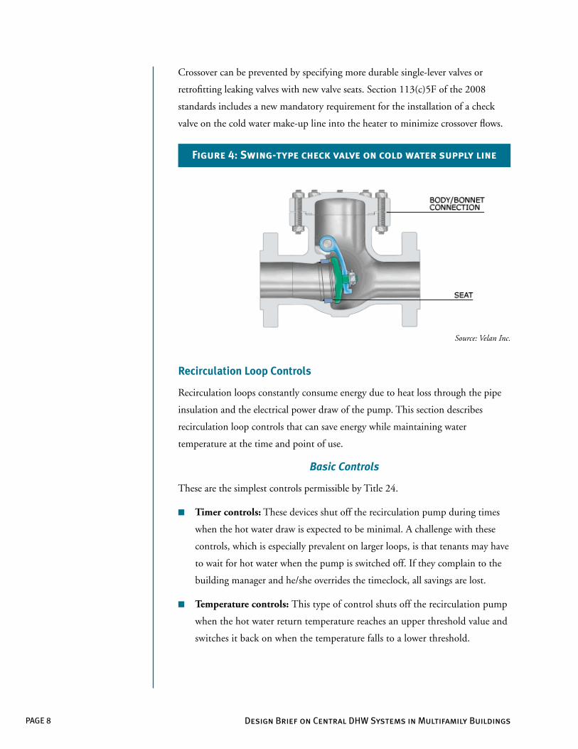
Crossover can be prevented by specifying more durable single-lever valves or
retrofitting leaking valves with new valve seats. Section 113(c)5F of the 2008
standards includes a new mandatory requirement for the installation of a check
valve on the cold water make-up line into the heater to minimize crossover flows.
Recirculation Loop Controls
Recirculation loops constantly consume energy due to heat loss through the pipe
insulation and the electrical power draw of the pump. This section describes
recirculation loop controls that can save energy while maintaining water
temperature at the time and point of use.
Basic Controls
These are the simplest controls permissible by Title 24.
n Timer controls: These devices shut off the recirculation pump during times
when the hot water draw is expected to be minimal. A challenge with these
controls, which is especially prevalent on larger loops, is that tenants may have
to wait for hot water when the pump is switched off. If they complain to the
building manager and he/she overrides the timeclock, all savings are lost.
n Temperature controls: This type of control shuts off the recirculation pump
when the hot water return temperature reaches an upper threshold value and
switches it back on when the temperature falls to a lower threshold.
Figure 4: Swing-type check valve on cold water supply line
Source: Velan Inc.
PAGE 9Design Brief on Central DHW Systems in Multifamily Buildings
Advanced Controls
More advanced controls likely offer better service, more robust savings, and
are eligible for credits within 2008 Title 24. Since there is little design guidance
available for these systems, it is advised to consult with the controls manufacturer
to ensure the product is compatible with your system. Some advanced controls
offer continuous monitoring to detect failures and identify savings opportunities.
n Demand Controls: These controls charge the loop with hot water in response
to either demand or a combination of demand and temperature. ‘Demand’
may be signaled by the user manually pressing a switch or activating a motion
sensor or detected by a flow sensor in the loop. The pump turns off when the
demand stops or a required return temperature is reached.
Demand controls can provide better service than timeclock controls by
eliminating the occasional long wait times. Additionally, they are a good
choice for use with shorter recirculation loops for two reasons. First, short
loops reduce the wait time for hot water, which increases the likelihood
tenants will accept the control system. Second, short loops serving only a
few apartments are likely to experience long periods of zero demand, during
which the system saves energy.
n Temperature Modulation Controls: These controls circulate hot water
continuously but save energy by reducing the storage tank temperature at
times of anticipated low demand. Temperature modulation controls can
function on a fixed schedule or adapt their schedule to measured demand
and are, thus, classified as ‘monitoring control systems’ by Title 24.
This control is a good choice for longer recirculation loops that serve many
apartments since demand controls may not provide a fast enough response.
They also allow for a smaller recirculation pump.
PAGE 10 Design Brief on Central DHW Systems in Multifamily Buildings
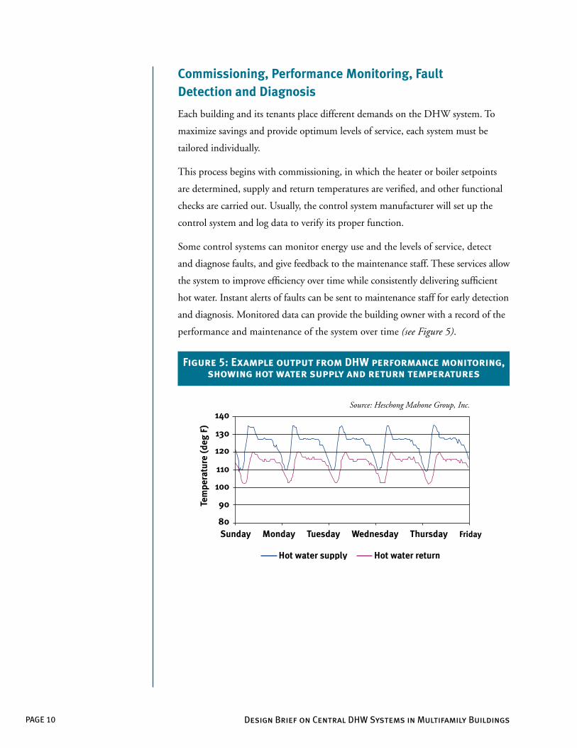
Commissioning, Performance Monitoring, Fault Detection and Diagnosis
Each building and its tenants place different demands on the DHW system. To
maximize savings and provide optimum levels of service, each system must be
tailored individually.
This process begins with commissioning, in which the heater or boiler setpoints
are determined, supply and return temperatures are verified, and other functional
checks are carried out. Usually, the control system manufacturer will set up the
control system and log data to verify its proper function.
Some control systems can monitor energy use and the levels of service, detect
and diagnose faults, and give feedback to the maintenance staff. These services allow
the system to improve efficiency over time while consistently delivering sufficient
hot water. Instant alerts of faults can be sent to maintenance staff for early detection
and diagnosis. Monitored data can provide the building owner with a record of the
performance and maintenance of the system over time (see Figure 5).
Figure 5: Example output from DHW performance monitoring, showing hot water supply and return temperatures
Source: Heschong Mahone Group, Inc.
PAGE 11Design Brief on Central DHW Systems in Multifamily Buildings
Title 24 Code Sections for DHW: Section 113 – Mandatory requirements for service water-heating systems and equipment (all occupancies)
Section 123 – Mandatory requirements for pipe insulation (high-rise residential)
Section 145 – Prescriptive requirements for service water heating systems (high-rise residential)
Section 150j – Mandatory features and devices (low-rise residential)
Section 151a, 151(f )8 – Performance and prescriptive compliance approaches (low-rise residential)
The full text of the Title 24 standards, along with the manuals and alternative compliance methods, can be found at www.energy.ca.gov/title24
Code Provisions Set Baseline for Energy Performance
The 2005 and 2008 California Building Energy Efficiency Standards (Title 24)
significantly altered the way central DHW systems are treated in compliance
calculations and set revised baseline energy performance criteria for them. This
section explains some key compliance options. It should not, however, serve as
a substitute for reading the standards themselves; Title 24 contains more
requirements than those discussed here.
Mandatory Requirements
The 2005 Title 24 standards incorporated a significant change to the requirements
in Section 113(c) 2 by mandating that recirculation systems have a control capable
of automatically turning off the system.1 Low-cost compliance options include:
n Timer Controls - Must initially be set to operate the pump for no more than
sixteen (16) hours per day
n Temperature Controls - Must have a temperature sensor installed on the
return line that has a ‘deadband’ (the difference between the temperature at
which the pump is switched on and that at which it is switched off ) of less
than 20°F
Additionally, Section 113(c)5 of 2008 Title 24 requires supplementary valves to
prevent crossover flows and the formation of air bubbles.
1 For recirculation loops, ‘the system’ means the pump; for heat trace it means the heating elements.
PAGE 12 Design Brief on Central DHW Systems in Multifamily Buildings
As detailed in Table123-A of the 2008 code, one (1) inch of insulation must be
provided on pipes up to two (2) inches diameter in recirculation loops, one and
one half (1½) inches on thicker pipes, and one half (½) inch on runouts. It is
important to note that there is little additional energy benefit to installing higher
levels of insulation than those specified.
Prescriptive Requirements
Per Section 151(f ) 8 C-E of 2008 Title 24, central DHW systems are now a
prescriptive compliance option. To comply, water heating equipment must meet
minimum efficiency standards (Title 20), the system must use a recirculation loop,
and the pipes to the kitchen fixtures must be insulated. Additionally, buried pipes
are required to be encased in a waterproof, non-crushable, insulated sleeve.
Performance Requirements
Starting with the 2005 standards, DHW calculations are done hourly, similar
to those of other end uses like heating and cooling, and include the impacts of
Time Dependent Valuation (TDV). Heat losses through recirculation pipes are
specifically assessed through hourly calculations based on pipe location, length of
pipe, and pipe diameter. Based on these results, the code provides incentives for
locating pipes in conditioned or semi-conditioned spaces and disincentives for
large pipes run underground or exposed to outside air.
Perhaps the biggest change has been the evaluation of central DHW systems
in performance calculations. Per Section 151(b) 1, the code now compares a
central DHW system with recirculation loop and controls to an equivalent system
rather than to individual water heaters. This modification reduced the typical
margin of compliance for central DHW systems with recirculation loops in the
performance calculations.
The 2008 code incorporates a 20% credit in the calculation of distribution
system losses for recirculation loop controls that work based on hot water demand
and monitoring control systems that can assist in fault diagnosis. The eligibility
requirements for each type of control are specified in Appendix RA4.4.9.2 of the
Residential Appendices to Title 24.
PAGE 13
High-rise vs. low-rise buildings: Alternative calculation methods (ACMs) for single family and low-rise multifamily buildings are set out in the Residential ACM Approval Manual.
Methods for high-rise multifamily (four stories or more) are set out in the Nonresidential ACM Approval Manual.
For service water heating in high-rise residential buildings, the Nonresidential ACM refers to the Residential ACM, so all multifamily buildings use the same calculations, irrespective of the building’s height.
Resources for Designers and Contractors:
n Title 24 Energy Efficiency Standards: www.energy.ca.gov/title24
n DHW System design:
o American Society of Plumbing Engineers Domestic Water Heating
Design Manual - 2nd Edition, ASPE, Chicago, IL
o American Society of Heating, Refrigerating, and Air-Conditioning
Engineers (ASHRAE), ASHRAE Handbook: 2003 HVAC
Applications. ASHRAE, Atlanta, GA
n Energy Efficiency Programs for Multifamily Buildings:
http://h-m-g.com/multifamily
n IRS tax credits for home builders:
http://www.energystar.gov/index.cfm?c=products.pr_tax_credits#s6
Acknowledgements
SACRAMENTO MUNICIPAL UTILITY DISTRICTThe Power To Do More.®


![· [4] DHW PRODUCTION/STORAGE TANKS MODELS CAPACITIES DHW / TOTAL (l.) STAINLESS STEEL MATERIAL STANDARD DHW PRODUCTION TYPE/SYSTEM OPTIONAL DHW PRODUCTION SYSTEM STAINLESS STEEL](https://static.fdocuments.in/doc/165x107/5f5c613d17a42d66c03c4e61/4-dhw-productionstorage-tanks-models-capacities-dhw-total-l-stainless-steel.jpg)