Technical Report Demonstration of Crack Arrestability of ... · model. As a result, among the...
6
NIPPON STEEL & SUMITOMO METAL TECHNICAL REPORT No. 107 FEBRUARY 2015 - 38 - 1. Introduction With the continually growing need for natural gas, there is now considerable market demand for higher strength natural gas line pipes. Constructing high-pressure pipelines using ultrahigh-strength steel pipes allows gas companies to reduce the total cost of transpor- tation of natural gas. Japanese steel pipe manufacturers have suc- cessfully developed ultrahigh-strength steel pipes, such as X100 and X120, in response to market demand. 1) But before steel pipes can be used for trunk pipelines, it is essen- tial that their structural reliability be verified. In particular, to pre- vent a major disaster caused by a dynamic ductile fracture in steel pipes, their performance must be clearly identified before they are put into use. However, the results of studies in recent years show that crack arrestability of ultrahigh-strength steel pipes can hardly be evaluated accurately through conventional techniques, and that the only solution to this particular problem is to verify crack arresta- bility through a full-scale burst test. A full-scale burst test using ultrahigh-strength steel pipes X100 or X120 has frequently been carried out in recent years to verify their crack arrestability. 2-8) However, none of the steel pipes tested clearly showed adequate crack arrestability. Therefore, it is reported that using a crack arrester is indispensable when employing an ultra- high-strength steel pipe for a trunk pipeline, since depending only on the crack arrestability of any ultrahigh-strength steel pipe is in- sufficient. 2. Dynamic Ductile Fracture in Pipelines Figure 1 schematically shows a dynamic ductile fracture in a pipeline. Natural gas pipelines are known to be susceptible to dy- namic ductile fractures (a fracture whereby a crack can propagate over a long distance with speeds as high as 100 to 400 m/s). In order to elucidate this phenomenon, it is necessary to accurately estimate the gas decompression curve, which expresses the relationship be- tween the pressure inside the pipe and the traveling speed of decom- pression gas waves, and to also accurately estimate the crack veloci- ty curve, which expresses the relationship between the pressure at Technical Report UDC 669 . 14 . 018 . 292 - 462 . 2 : 620 . 178 . 2 * Senior Researcher, Dr.Eng., Materials Reliability Research Lab., Steel Research Laboratories 1-8 Fuso-cho, Amagasaki City, Hyogo Pref. 660-0891 Demonstration of Crack Arrestability of X100 Line Pipe and Development of Evaluation Technologies for Three-dimensional Fracture Process Hiroyuki MAKINO* Toshihiko AMANO Abstract It is said that crack arrestablity of the ultra high-strength line pipe (equal or above X100) is not enough and use of the crack arrester is required in application to the gas transmission trunk line of these line pipes. We carried out an X100 full-scale burst test using flat-type toughness arrangement based on the analyzed results by an originally developed simulation model. As a result, among the full-scale burst tests using X100 line pies, clear crack arrest within a short distance on both sides was observed for the first time in the world. The test has been successful in demonstrating the crack arrestability of X100 line pipe. And, for the behavior of propagating shear fracture, the evaluation technologies for three-dimensional fracture process were developed. Fig. 1 Schematic illustration of propagating shear fracture in natural gas pipeline
Transcript of Technical Report Demonstration of Crack Arrestability of ... · model. As a result, among the...
NIPPON STEEL & SUMITOMO METAL TECHNICAL REPORT No. 107 FEBRUARY 2015
- 38 -
1. IntroductionWith the continually growing need for natural gas, there is now
considerable market demand for higher strength natural gas line pipes. Constructing high-pressure pipelines using ultrahigh-strength steel pipes allows gas companies to reduce the total cost of transpor-tation of natural gas. Japanese steel pipe manufacturers have suc-cessfully developed ultrahigh-strength steel pipes, such as X100 and X120, in response to market demand.1)
But before steel pipes can be used for trunk pipelines, it is essen-tial that their structural reliability be verified. In particular, to pre-vent a major disaster caused by a dynamic ductile fracture in steel pipes, their performance must be clearly identified before they are put into use. However, the results of studies in recent years show that crack arrestability of ultrahigh-strength steel pipes can hardly be evaluated accurately through conventional techniques, and that the only solution to this particular problem is to verify crack arresta-bility through a full-scale burst test.
A full-scale burst test using ultrahigh-strength steel pipes X100 or X120 has frequently been carried out in recent years to verify their crack arrestability.2-8) However, none of the steel pipes tested clearly showed adequate crack arrestability. Therefore, it is reported that using a crack arrester is indispensable when employing an ultra-high-strength steel pipe for a trunk pipeline, since depending only
on the crack arrestability of any ultrahigh-strength steel pipe is in-sufficient.
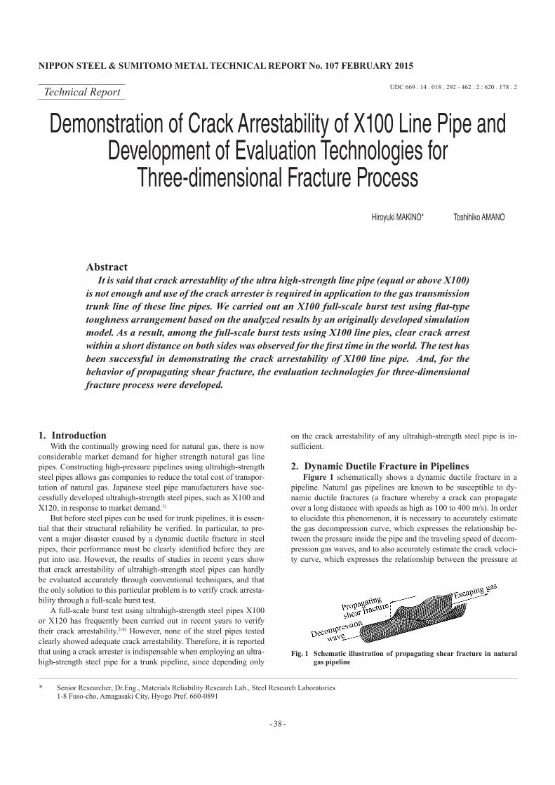
2. Dynamic Ductile Fracture in PipelinesFigure 1 schematically shows a dynamic ductile fracture in a
pipeline. Natural gas pipelines are known to be susceptible to dy-namic ductile fractures (a fracture whereby a crack can propagate over a long distance with speeds as high as 100 to 400 m/s). In order to elucidate this phenomenon, it is necessary to accurately estimate the gas decompression curve, which expresses the relationship be-tween the pressure inside the pipe and the traveling speed of decom-pression gas waves, and to also accurately estimate the crack veloci-ty curve, which expresses the relationship between the pressure at
Technical Report UDC 669 . 14 . 018 . 292 - 462 . 2 : 620 . 178 . 2
* Senior Researcher, Dr.Eng., Materials Reliability Research Lab., Steel Research Laboratories 1-8 Fuso-cho, Amagasaki City, Hyogo Pref. 660-0891
Demonstration of Crack Arrestability of X100 Line Pipe and Development of Evaluation Technologies for
Three-dimensional Fracture ProcessHiroyuki MAKINO* Toshihiko AMANO
AbstractIt is said that crack arrestablity of the ultra high-strength line pipe (equal or above X100)
is not enough and use of the crack arrester is required in application to the gas transmission trunk line of these line pipes. We carried out an X100 full-scale burst test using flat-type toughness arrangement based on the analyzed results by an originally developed simulation model. As a result, among the full-scale burst tests using X100 line pies, clear crack arrest within a short distance on both sides was observed for the first time in the world. The test has been successful in demonstrating the crack arrestability of X100 line pipe. And, for the behavior of propagating shear fracture, the evaluation technologies for three-dimensional fracture process were developed.
Fig. 1 Schematic illustration of propagating shear fracture in natural gas pipeline
NIPPON STEEL & SUMITOMO METAL TECHNICAL REPORT No. 107 FEBRUARY 2015
- 39 -
the leading edge of the crack and the velocity of crack propagation.A gas decompression curve is estimated by calculating the
change in pressure inside a pipe having a semi-infinite length, caused by an adiabatic expansion when the end of the pipe is made open. To estimate the crack velocity curve, two formulas are avail-able—the Battelle formula 9, 10) proposed by the Battelle Memorial Institute of the U.S. and the HLP formula 11, 12) proposed by the HLP Committee of the Iron and Steel Institute of Japan. Both formulas are semi-empirical ones. Although they allow fairly accurate estima-tions under conditions which are based on the original experimental data used in the process of their development, the scope of their ap-plication is limited.
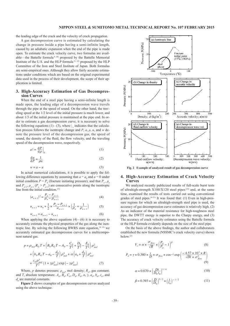
3. High-Accuracy Estimation of Gas Decompres-sion CurvesWhen the end of a steel pipe having a semi-infinite length is
made open, the leading edge of a decompression wave travels through the pipe at the speed of sound. On the other hand, the trav-eling speed at the 1/2 level of the initial pressure is much lower, and about 1/3 of the initial pressure is maintained at the pipe end. In or-der to estimate a gas decompression curve, it is necessary to solve the following equations (1) – (3), where | s indicates that the calcula-tion process follows the isentropic change and P, a, ρ, u, and w de-note the pressure level of the decompression gas, the speed of sound, the density of the fluid, the flow velocity, and the traveling speed of the decompression wave, respectively.
a2 = dPdρ S (1)
dudP =
1ρa (2)
w = a − u (3)In actual numerical calculations, it is possible to apply the fol-
lowing difference equations by assuming that a = a0 and u = 0 under initial condition P = P0 (fracture initiating pressure), and that Pn , ρn and Pn+1, ρn+1 (Pn > Pn+1) are consecutive points along the isentropic line from the initial condition.13)
an + 1 2 = Pn − Pn + 1ρn − ρn + 1 (4)
un + 1 = un +12 ×
Pn − Pn + 1an + 1 × 1
ρn+ 1ρn + 1 (5)
wn + 1 = an + 1 − un + 1 (6)When applying the above equations (4) – (6) it is necessary to
accurately estimate the physical properties of the gas along the isen-tropic line. By solving the following BWRS state equation,14, 15) we accurately estimated gas decompression curves for a multicompo-nent natural gas.
p = ρmol RG T + B0RGT − A0 −C0T 2 +
D0T 3 −
E0T 4 ρmol
2
+ b0RGT − a0 −d0T ρmol
3 + α a0 +d0T ρmol
6
+c0ρmol3
T 2 1 + γρmol2 exp − γρmol2
(7)
Where, p denotes pressure; ρmol, mol density; RG, gas constant; and T, absolute temperature. A0 , B0 , C0 , D0 , E0 , α, γ, a0 , b0 , c0 , and d0 are material constants.
Figure 2 shows examples of gas decompression curves analyzed using the above technique.
4. High-Accuracy Estimation of Crack Velocity CurvesWe analyzed recently publicized results of full-scale burst tests
of ultrahigh-strength X100/X120 steel pipes 2-8) and, at the same time, examined the results of tests carried out using conventional grades of steel pipes.16-21) It was found that: (1) Even in high-pres-sure regions for which an ultrahigh-strength steel pipe is used, the accuracy of gas decompression curve estimates is relatively high, (2) As an indicator of the material resistance for high-toughness steel pipe, the DWTT energy is superior to the Charpy energy, and (3) The accuracy of crack velocity estimates using the Battelle formula or the HLP formula evidently depends on the size of the steel pipe.
On the basis of the above findings, the author and collaborators established the new formula (NSSMC’s crack velocity curve) shown below.22)
Vc = α ×
σ flowR ×
PdPa− 1
β
(8)
Pa = γ × 0.380 × tD × σ flow × cos−1 exp
− 4.57 × 10⁷ × RDt × σ flow
2
(9)
α = 0.670 × Dt
D0 t01 / 4
(10)
β = 0.393 × D
D05 / 2 × t
t0− 1 / 2
(11)
Fig. 2 Example of analyzed result of gas decompression curve
NIPPON STEEL & SUMITOMO METAL TECHNICAL REPORT No. 107 FEBRUARY 2015
- 40 -
γ = 3.423.22 + 0.20 × t / D
t0 / D03
(12)
D0 = 1219.2 mm
(13)
t0 = 18.3 mm
(14)
σ flow = σ y + σ T / 2
(15)
R = Dp est / Ap
(16)
Dp est = 3.29 × t 1.5 × Cv
0.544
(17)
Where, Vc represents crack velocity (m/s); σflow , flow stress (MPa); R, material resistance (Joules/mm2); Pd , crack tip pressure (MPa); Pα , crack arrest pressure (MPa); t, pipe wall thickness (mm); D, pipe di-ameter (mm); σy , yield stress (MPa); σT , tensile strength (MPa); Dp (est), estimated value of pre-crack DWTT energy (Joules); Ap , liga-ment area of pre-crack DWTT energy (mm2); and Cv , full-size Charpy energy (Joules).
This newly developed crack velocity formula is characteristic in that the three constants built in the conventional formulas (Battelle/HLP) in accordance with limited experimental data are replaced with variables (α, β, γ), given as functions of the steel pipe size (di-ameter and wall thickness), and that the crack velocity curves esti-mated gradually come close to the curves estimated by the conven-tional formulas, as far as the experimental data on which they are based are concerned.
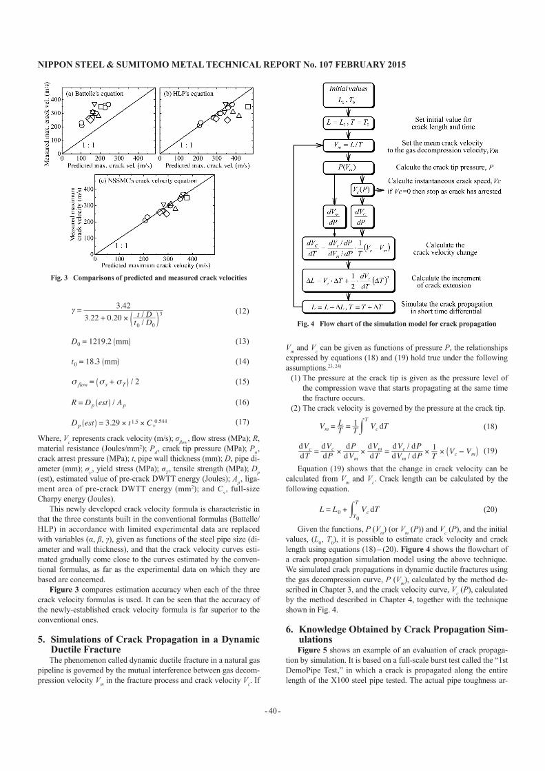
Figure 3 compares estimation accuracy when each of the three crack velocity formulas is used. It can be seen that the accuracy of the newly-established crack velocity formula is far superior to the conventional ones.
5. Simulations of Crack Propagation in a Dynamic Ductile FractureThe phenomenon called dynamic ductile fracture in a natural gas
pipeline is governed by the mutual interference between gas decom-pression velocity Vm in the fracture process and crack velocity Vc. If
Vm and Vc can be given as functions of pressure P, the relationships expressed by equations (18) and (19) hold true under the following assumptions.23, 24)
(1) The pressure at the crack tip is given as the pressure level of the compression wave that starts propagating at the same time the fracture occurs.
(2) The crack velocity is governed by the pressure at the crack tip.
Vm = LT =
1T Vc dT
T
(18)
dVcdT = dVcdP ×
dPdVm
×dVmdT = dVc / dPdVm / dP
× 1T × Vc − Vm (19)
Equation (19) shows that the change in crack velocity can be calculated from Vm and Vc. Crack length can be calculated by the following equation.
L = L0 + Vc dT
T0
T
(20)
Given the functions, P (Vm) (or Vm (P)) and Vc (P), and the initial values, (L0 , T0), it is possible to estimate crack velocity and crack length using equations (18) – (20). Figure 4 shows the flowchart of a crack propagation simulation model using the above technique. We simulated crack propagations in dynamic ductile fractures using the gas decompression curve, P (Vm), calculated by the method de-scribed in Chapter 3, and the crack velocity curve, Vc (P), calculated by the method described in Chapter 4, together with the technique shown in Fig. 4.
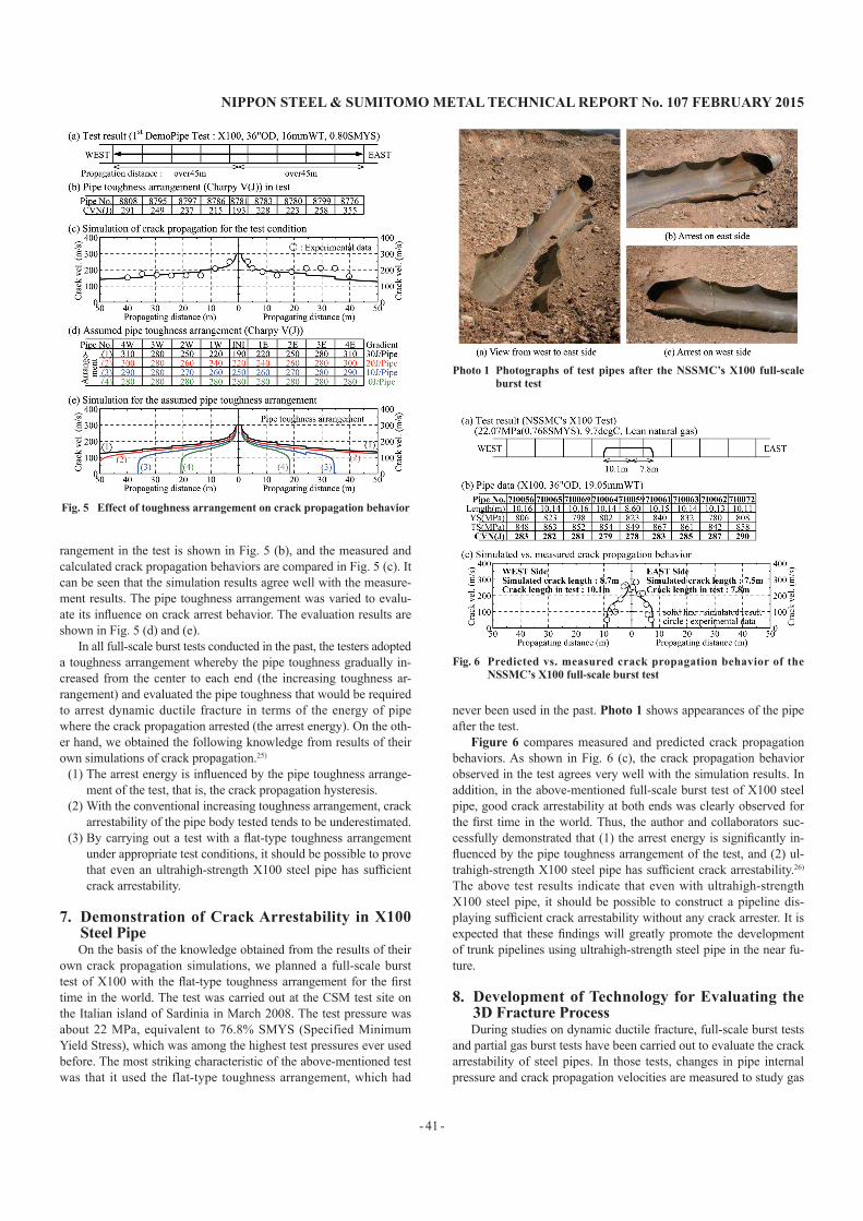
6. Knowledge Obtained by Crack Propagation Sim-ulationsFigure 5 shows an example of an evaluation of crack propaga-
tion by simulation. It is based on a full-scale burst test called the “1st DemoPipe Test,” in which a crack is propagated along the entire length of the X100 steel pipe tested. The actual pipe toughness ar-
Fig. 3 Comparisons of predicted and measured crack velocities
Fig. 4 Flow chart of the simulation model for crack propagation
NIPPON STEEL & SUMITOMO METAL TECHNICAL REPORT No. 107 FEBRUARY 2015
- 41 -
rangement in the test is shown in Fig. 5 (b), and the measured and calculated crack propagation behaviors are compared in Fig. 5 (c). It can be seen that the simulation results agree well with the measure-ment results. The pipe toughness arrangement was varied to evalu-ate its influence on crack arrest behavior. The evaluation results are shown in Fig. 5 (d) and (e).
In all full-scale burst tests conducted in the past, the testers adopted a toughness arrangement whereby the pipe toughness gradually in-creased from the center to each end (the increasing toughness ar-rangement) and evaluated the pipe toughness that would be required to arrest dynamic ductile fracture in terms of the energy of pipe where the crack propagation arrested (the arrest energy). On the oth-er hand, we obtained the following knowledge from results of their own simulations of crack propagation.25)
(1) The arrest energy is influenced by the pipe toughness arrange-ment of the test, that is, the crack propagation hysteresis.
(2) With the conventional increasing toughness arrangement, crack arrestability of the pipe body tested tends to be underestimated.
(3) By carrying out a test with a flat-type toughness arrangement under appropriate test conditions, it should be possible to prove that even an ultrahigh-strength X100 steel pipe has sufficient crack arrestability.
7. Demonstration of Crack Arrestability in X100 Steel PipeOn the basis of the knowledge obtained from the results of their
own crack propagation simulations, we planned a full-scale burst test of X100 with the flat-type toughness arrangement for the first time in the world. The test was carried out at the CSM test site on the Italian island of Sardinia in March 2008. The test pressure was about 22 MPa, equivalent to 76.8% SMYS (Specified Minimum Yield Stress), which was among the highest test pressures ever used before. The most striking characteristic of the above-mentioned test was that it used the flat-type toughness arrangement, which had
never been used in the past. Photo 1 shows appearances of the pipe after the test.
Figure 6 compares measured and predicted crack propagation behaviors. As shown in Fig. 6 (c), the crack propagation behavior observed in the test agrees very well with the simulation results. In addition, in the above-mentioned full-scale burst test of X100 steel pipe, good crack arrestability at both ends was clearly observed for the first time in the world. Thus, the author and collaborators suc-cessfully demonstrated that (1) the arrest energy is significantly in-fluenced by the pipe toughness arrangement of the test, and (2) ul-trahigh-strength X100 steel pipe has sufficient crack arrestability.26) The above test results indicate that even with ultrahigh-strength X100 steel pipe, it should be possible to construct a pipeline dis-playing sufficient crack arrestability without any crack arrester. It is expected that these findings will greatly promote the development of trunk pipelines using ultrahigh-strength steel pipe in the near fu-ture.
8. Development of Technology for Evaluating the 3D Fracture ProcessDuring studies on dynamic ductile fracture, full-scale burst tests
and partial gas burst tests have been carried out to evaluate the crack arrestability of steel pipes. In those tests, changes in pipe internal pressure and crack propagation velocities are measured to study gas
Fig. 5 Effect of toughness arrangement on crack propagation behavior
Photo 1 Photographs of test pipes after the NSSMC’s X100 full-scale burst test
Fig. 6 Predicted vs. measured crack propagation behavior of the NSSMC’s X100 full-scale burst test
NIPPON STEEL & SUMITOMO METAL TECHNICAL REPORT No. 107 FEBRUARY 2015
- 42 -
decompression behavior and crack arrest behavior. However, the three-dimensional process of fracture in a cracked steel pipe has very seldom been evaluated directly. This is owing to (1) the diffi-culty involved in directly observing the phenomenon of dynamic ductile fracture that propagates at speeds as high as several hundred meters per second and (2) the difficulty involved in directly resolv-ing, using computational dynamics, the three-dimensional problem of interaction between steel pipe deformation and internal fluid out-flow.
However, we have pressed ahead proactively with the develop-ment of a technique for evaluating that three-dimensional fracture process, in the belief that this will help clarify fracture mechanisms and establish a next-generation evaluation technique that is more ac-curate and has a wider scope of application. In recent years, they achieved a measure of success in this particular field, too, as de-scribed below.
As mentioned above, dynamic ductile fracture is a phenomenon whereby a fracture propagates several hundred meters per second. Such a three-dimensional fracture process had never been directly observed in the past. We recently succeeded in direct observation of that process using a high-speed camera installed as part of their test equipment. Photo 2 shows examples of photographic images of the process. The photographic system has made it possible to directly observe the three-dimensional steel pipe fracture process and the three-dimensional internal fluid outflow process during rapid propa-gation of a crack in the steel pipe.
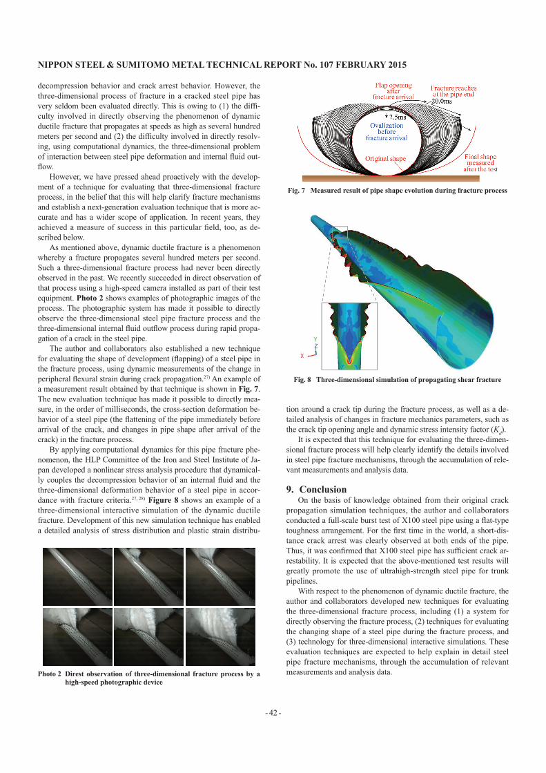
The author and collaborators also established a new technique for evaluating the shape of development (flapping) of a steel pipe in the fracture process, using dynamic measurements of the change in peripheral flexural strain during crack propagation.27) An example of a measurement result obtained by that technique is shown in Fig. 7. The new evaluation technique has made it possible to directly mea-sure, in the order of milliseconds, the cross-section deformation be-havior of a steel pipe (the flattening of the pipe immediately before arrival of the crack, and changes in pipe shape after arrival of the crack) in the fracture process.
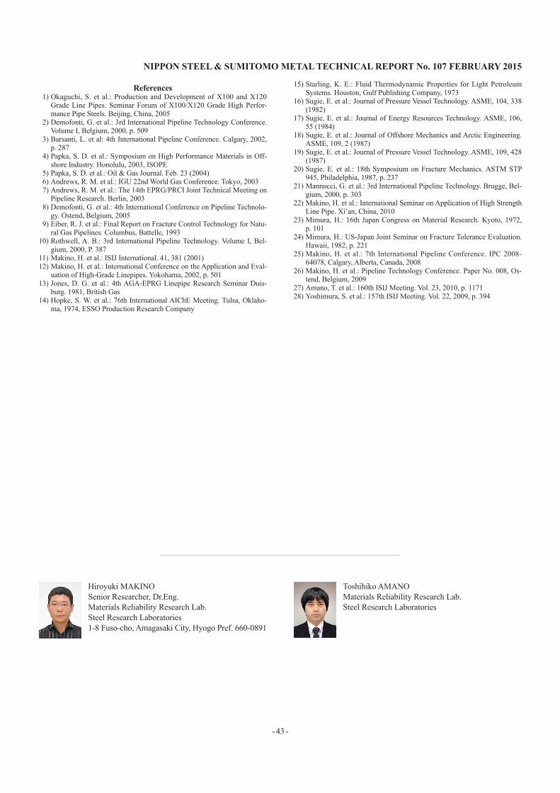
By applying computational dynamics for this pipe fracture phe-nomenon, the HLP Committee of the Iron and Steel Institute of Ja-pan developed a nonlinear stress analysis procedure that dynamical-ly couples the decompression behavior of an internal fluid and the three-dimensional deformation behavior of a steel pipe in accor-dance with fracture criteria.27, 28) Figure 8 shows an example of a three-dimensional interactive simulation of the dynamic ductile fracture. Development of this new simulation technique has enabled a detailed analysis of stress distribution and plastic strain distribu-
tion around a crack tip during the fracture process, as well as a de-tailed analysis of changes in fracture mechanics parameters, such as the crack tip opening angle and dynamic stress intensity factor (Kd).
It is expected that this technique for evaluating the three-dimen-sional fracture process will help clearly identify the details involved in steel pipe fracture mechanisms, through the accumulation of rele-vant measurements and analysis data.
9. ConclusionOn the basis of knowledge obtained from their original crack
propagation simulation techniques, the author and collaborators conducted a full-scale burst test of X100 steel pipe using a flat-type toughness arrangement. For the first time in the world, a short-dis-tance crack arrest was clearly observed at both ends of the pipe. Thus, it was confirmed that X100 steel pipe has sufficient crack ar-restability. It is expected that the above-mentioned test results will greatly promote the use of ultrahigh-strength steel pipe for trunk pipelines.
With respect to the phenomenon of dynamic ductile fracture, the author and collaborators developed new techniques for evaluating the three-dimensional fracture process, including (1) a system for directly observing the fracture process, (2) techniques for evaluating the changing shape of a steel pipe during the fracture process, and (3) technology for three-dimensional interactive simulations. These evaluation techniques are expected to help explain in detail steel pipe fracture mechanisms, through the accumulation of relevant measurements and analysis data.Photo 2 Direst observation of three-dimensional fracture process by a
high-speed photographic device
Fig. 7 Measured result of pipe shape evolution during fracture process
Fig. 8 Three-dimensional simulation of propagating shear fracture
NIPPON STEEL & SUMITOMO METAL TECHNICAL REPORT No. 107 FEBRUARY 2015
- 43 -
References1) Okaguchi, S. et al.: Production and Development of X100 and X120
Grade Line Pipes. Seminar Forum of X100/X120 Grade High Perfor-mance Pipe Steels. Beijing, China, 2005
2) Demofonti, G. et al.: 3rd International Pipeline Technology Conference. Volume I, Belgium, 2000, p. 509
3) Barsanti, L. et al: 4th International Pipeline Conference. Calgary, 2002, p. 287
4) Papka, S. D. et al.: Symposium on High Performance Materials in Off-shore Industry. Honolulu, 2003, ISOPE
5) Papka, S. D. et al.: Oil & Gas Journal. Feb. 23 (2004)6) Andrews, R. M. et al.: IGU 22nd World Gas Conference. Tokyo, 20037) Andrews, R. M. et al.: The 14th EPRG/PRCI Joint Technical Meeting on
Pipeline Research. Berlin, 20038) Demofonti, G. et al.: 4th International Conference on Pipeline Technolo-
gy. Ostend, Belgium, 20059) Eiber, R. J. et al.: Final Report on Fracture Control Technology for Natu-
ral Gas Pipelines. Columbus, Battelle, 199310) Rothwell, A. B.: 3rd International Pipeline Technology. Volume I, Bel-
gium, 2000, P. 38711) Makino, H. et al.: ISIJ International. 41, 381 (2001)12) Makino, H. et al.: International Conference on the Application and Eval-
uation of High-Grade Linepipes. Yokohama, 2002, p. 50113) Jones, D. G. et al.: 4th AGA-EPRG Linepipe Research Seminar Duis-
burg. 1981, British Gas14) Hopke, S. W. et al.: 76th International AIChE Meeting. Tulsa, Oklaho-
ma, 1974, ESSO Production Research Company
15) Starling, K. E.: Fluid Thermodynamic Properties for Light Petroleum Systems. Houston, Gulf Publishing Company, 1973
16) Sugie, E. et al.: Journal of Pressure Vessel Technology. ASME, 104, 338 (1982)
17) Sugie, E. et al.: Journal of Energy Resources Technology. ASME, 106, 55 (1984)
18) Sugie, E. et al.: Journal of Offshore Mechanics and Arctic Engineering. ASME, 109, 2 (1987)
19) Sugie, E. et al.: Journal of Pressure Vessel Technology. ASME, 109, 428 (1987)
20) Sugie, E. et al.: 18th Symposium on Fracture Mechanics. ASTM STP 945, Philadelphia, 1987, p. 237
21) Mannucci, G. et al.: 3rd International Pipeline Technology. Brugge, Bel-gium, 2000, p. 303
22) Makino, H. et al.: International Seminar on Application of High Strength Line Pipe. Xi’an, China, 2010
23) Mimura, H.: 16th Japan Congress on Material Research. Kyoto, 1972, p. 101
24) Mimura, H.: US-Japan Joint Seminar on Fracture Tolerance Evaluation. Hawaii, 1982, p. 221
25) Makino, H. et al.: 7th International Pipeline Conference. IPC 2008-64078, Calgary, Alberta, Canada, 2008
26) Makino, H. et al.: Pipeline Technology Conference. Paper No. 008, Os-tend, Belgium, 2009
27) Amano, T. et al.: 160th ISIJ Meeting. Vol. 23, 2010, p. 117128) Yoshimura, S. et al.: 157th ISIJ Meeting. Vol. 22, 2009, p. 394
Hiroyuki MAKINOSenior Researcher, Dr.Eng.Materials Reliability Research Lab.Steel Research Laboratories1-8 Fuso-cho, Amagasaki City, Hyogo Pref. 660-0891
Toshihiko AMANOMaterials Reliability Research Lab.Steel Research Laboratories