TRAXALL X100-SERIES TRANSMITTER USER GUIDE 13 MAR 2017 X100-SERIES TRANSMITTE… · The X100 is a...
48
MULTIFREQUENCY PIPELINE PIG TRACKING TRANSMITTERS Models X100-1N, X100-2N, X100-3N, X100-4N, and X100-5N X100-2N-SWX and X100-2N-RC 1801 North Juniper Avenue Broken Arrow, Oklahoma 74012 U.S.A. +1 (918) 258-6068 worldwide www.pigging.com [email protected] USER GUIDE TRAXALL
Transcript of TRAXALL X100-SERIES TRANSMITTER USER GUIDE 13 MAR 2017 X100-SERIES TRANSMITTE… · The X100 is a...

MULTIFREQUENCY PIPELINE PIG TRACKING TRANSMITTERSModels X100-1N, X100-2N, X100-3N, X100-4N, and X100-5NX100-2N-SWX and X100-2N-RC
1801 North Juniper AvenueBroken Arrow, Oklahoma 74012 U.S.A.+1 (918) 258-6068 worldwide
USER GUIDE
TRAXALL

WARNING
Any operation involving work on pipelines containing gases or liquids under pressure is potentially hazardous. It is necessary, therefore, to follow correct procedures in the use of this equipment to maintain a safe working environment. No person should use this equipment unless fully aware of potential hazards of working with pressurized pipelines and trained in the procedures stated in this manual.
The purchaser of this equipment is responsible for the training and competence of operators and the manner in which it is used.
Contact CDI immediately should any difficulty arise in the use of this equipment.
Page 2 of 48
TRAXALL X100 Series Multifrequency Transmitter User Guide
Information in this document is subject to change without notice and applies only to the version of software, hardware, or firmware described on the title page.
The software, hardware, and firmware described in this document are designed, manufactured, and written by CDI. The software and firmware copyright © 2014, 2016 CDI with all rights reserved.
This document © 2017 CDI. All rights reserved.Document Number 89-09-0041-00Manual Revision 13 Mar 2017
The TRAXALL family of transmitters is covered under United States Patent No. 9172406.
TRAXALL, TRAXALL Remote Control, FieldLink, and Configurator products are covered under United States Patents
Microsoft and Windows are U.S. registered trademarks of Microsoft Corporation.
Google Earth is a service of Google Inc.
Adobe, the Adobe logo, Acrobat, and Reader are either registered trademarks or trademarks of Adobe Systems Incorporated in the United States and/or other countries.

Page 3 of 48
TRAXALL X100 Series Multifrequency Transmitter User Guide
CONTENTS
INTRODUCTION ...................................................................................... 4
OVERVIEW ............................................................................................... 4
GETTING STARTED .................................................................................. 6
STEP 1. INSTALL CONFIGURATOR .......................................................... 8
STEP 2. ACTIVATE FIELDLINK................................................................ 11
STEP 3. LAUNCH CONFIGURATOR ....................................................... 12
STEP 4. ACTIVATE TRANSMITTER ........................................................ 13
STEP 5. PREPARE TRANSMITTER FOR CONFIGURATION ................... 20 STEP 6. RUN CONFIGURATOR .............................................................. 22
PLACING TRANSMITTER INTO SERVICE .............................................. 34
TROUBLESHOOTING ............................................................................. 35
REMOVING FROM SERVICE ................................................................. 37
APPENDIX A: TRANSMITTER BEHAVIOR ............................................. 38
APPENDIX B: SYSTEM SPECIFICATIONS .............................................. 41
APPENDIX C: SPECIAL APPLICATIONS ................................................. 42 X100-2N-SWX ...................................................................................... 42 X100-2N-RC .......................................................................................... 44 WARRANTY ............................................................................................ 45
CARE, MAINTENANCE, AND SERVICING ............................................. 46
NOTES .................................................................................................... 47
ABOUT CDI ............................................................................................ 48

Page 4 of 48
TRAXALL X100 Series Multifrequency Transmitter User Guide
WARNING
Always use caution when opening any CDI transmitter that has been in a pressurized environment.
It is possible for pressurized liquid or gas to leak into a transmitter and remain there even after the transmitter has been removed from the pipeline.
Always point the transmitter away from yourself or others when opening a cover or end cap.
INTRODUCTION
This User Guide will instruct you in the function, capabilities, use, and care of CDI X100 Series multifrequency pig-tracking transmitters.
OVERVIEW
Electromagnetic pipeline pig location and tracking transmitters
TRAXALL Multi-frequency transmitters operate by emitting electromagnetic fields at a very low frequency (between 17 and 32 Hz) as well as the industry-standard 22 Hz. This makes them safe and reliable for use in any onshore or offshore environment and any pipeline product (water, oil, gas, ammonia, carbon dioxide, etc.).
The X100 is a TRAXALL-compatible electromagnetic pipeline pig-tracking transmitter that offers both programmable frequency and power control through CDI’s proprietary FieldLink wireless communications system.

Page 5 of 48
TRAXALL X100 Series Multifrequency Transmitter User Guide
Configurator
Configurator is a Windows application that will let you customize transmitter frequency, pulse rate, and output power.
Requirements:
• PC or laptop computer with Windows® 7 or higher (32-bit or 64-bit]• Configurator software*• FieldLink USB device** • Adobe® Reader® is required to access the PDF Help menu

Page 6 of 48
TRAXALL X100 Series Multifrequency Transmitter User Guide
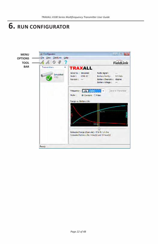
MENUOPTIONS
TOOLBAR
TRANSMITTER PANE
TRANSMITTERPROFILE PANE
CONFIGURATIONPANE
STATUS BAR
New for Configurator ver. 2.0 In addition to the menu options and a tool bar, Configurator 2.0 features three transmitter information and control panes. The next few pages will describe these controls and options in detail.
GETTING STARTED
Your transmitter requires little in the way of preparation. Simply activate FieldLink, launch Configurator, install fresh batteries, run Configurator to set transmission signal or power performance, and your transmitter is ready for a pigging run.

Page 7 of 48
TRAXALL X100 Series Multifrequency Transmitter User Guide
1. INSTALL CONFIGURATOR
From the main CDI web page, select Other, then FieldLink Configurator Software from the drop-down menu.

Page 8 of 48
TRAXALL X100 Series Multifrequency Transmitter User Guide
Scroll to the SOFTWARE DOWNLOAD tab.
Click on FieldLink Configurator Program to download latest version.
When download is complete, Open the installer and follow prompts.

Page 9 of 48
TRAXALL X100 Series Multifrequency Transmitter User Guide
The Windows Install Wizard will extract and install Configurator.
The Windows Install Wizard will extract and install Configurator.

Page 10 of 48
TRAXALL X100 Series Multifrequency Transmitter User Guide
The Windows Install Wizard will extract and install Configurator.Continue to follow prompts until Configurator is installed.The Program Maintenance window will appear only if your system already has Configurator installed. (This is where Configurator is modifed, “repaired,” or removed if/when necessary.)
Return to the SOFTWARE DOWNLOAD tab and install a USB driver for either 64-bit or 32-bit Windows. Follow installation prompts.
Page 11 of 48
TRAXALL X100 Series Multifrequency Transmitter User Guide
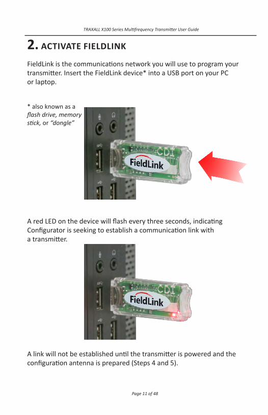
2. ACTIVATE FIELDLINK
FieldLink is the communications network you will use to program your transmitter. Insert the FieldLink device* into a USB port on your PC or laptop.
* also known as a flash drive, memory stick, or “dongle”
A red LED on the device will flash every three seconds, indicating Configurator is seeking to establish a communication link with a transmitter.
A link will not be established until the transmitter is powered and the configuration antenna is prepared (Steps 4 and 5).
Page 12 of 48
TRAXALL X100 Series Multifrequency Transmitter User Guide
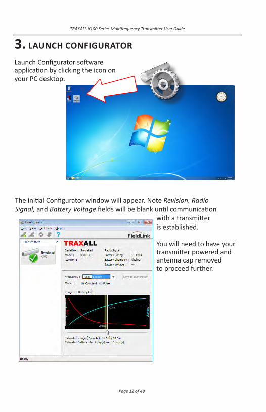
3. LAUNCH CONFIGURATOR
Launch Configurator software application by clicking the icon on your PC desktop.
The initial Configurator window will appear. Note Revision, Radio Signal, and Battery Voltage fields will be blank until communication
with a transmitter is established.
You will need to have your transmitter powered and antenna cap removed to proceed further.
Page 13 of 48
TRAXALL X100 Series Multifrequency Transmitter User Guide
NOTE: Transmitters have no “ON/OFF” switch, but are activated when batteries
are installed and battery cap is replaced.* Therefore, install batteries only when you are about to configure transmitter or beginning a pig run.
Power
X100 Series transmitters are powered by N-Cell alkaline batteries.
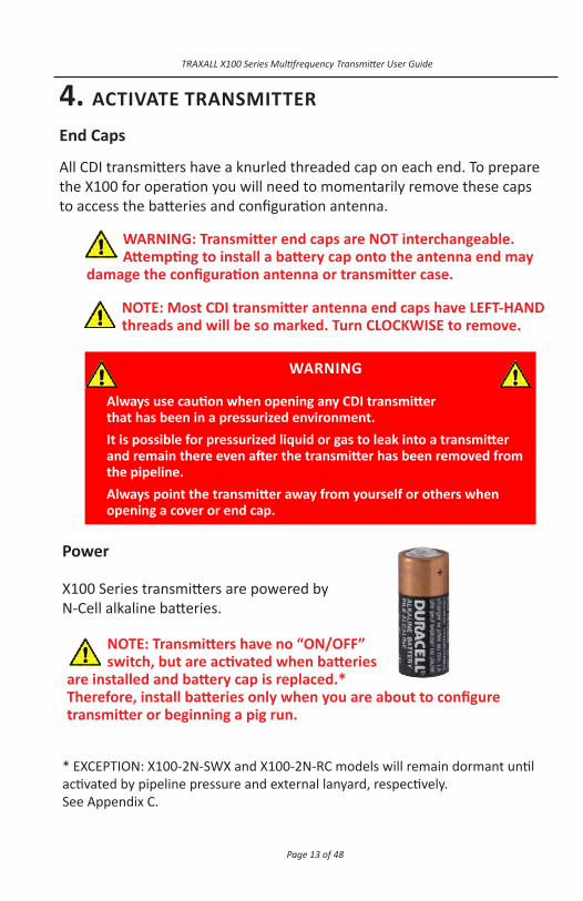
4. ACTIVATE TRANSMITTER
End Caps All CDI transmitters have a knurled threaded cap on each end. To prepare the X100 for operation you will need to momentarily remove these caps to access the batteries and configuration antenna.
WARNING: Transmitter end caps are NOT interchangeable. Attempting to install a battery cap onto the antenna end may
damage the configuration antenna or transmitter case.
NOTE: Most CDI transmitter antenna end caps have LEFT-HAND threads and will be so marked. Turn CLOCKWISE to remove.
WARNING
Always use caution when opening any CDI transmitter that has been in a pressurized environment. It is possible for pressurized liquid or gas to leak into a transmitter and remain there even after the transmitter has been removed from the pipeline. Always point the transmitter away from yourself or others when opening a cover or end cap.
* EXCEPTION: X100-2N-SWX and X100-2N-RC models will remain dormant until activated by pipeline pressure and external lanyard, respectively. See Appendix C.

Page 14 of 48
TRAXALL X100 Series Multifrequency Transmitter User Guide
NOTE: It is good practice to always install fresh batteries before deploying any pipeline pigging device.
WARNING
When installing batteries, replace all batteries at the same time.
When replacing batteries, use batteries from the same package or manufacturing batch whenever possible.
Do not mix alkaline and lithium batteries in the same device.
Always observe correct polarity when installing batteries.
(Polarity is provided on each transmitter case.)
Power (cont.)
The X100 is available in 1, 2, 3, 4, and 5-cell versions. They differ in performance, case dimensions (length) and number of batteries required, but configuration and battery installation procedures are essentially the same for all versions.
Observe nomenclature on transmitter case to determine correct cap, battery quantity, and battery polarity.
Install Batteries Unscrew battery cap by turning counter-clockwise (CCW).
ANTENNA CAP
BATTERY CAP

Page 15 of 48
TRAXALL X100 Series Multifrequency Transmitter User Guide
All batteries are to be inserted positive (+) end first as shown:
• X100-1N: Insert one (1) N-Cell battery• X100-2N: Insert two (2) N-Cell batteries• X100-3N: Insert three (3) N-Cell batteries• X100-4N: Insert four (4) N-Cell batteries• X100-5N: Insert five (5) N-Cell batteries
Battery quantity and polarity are marked on each transmitter case:
++USE N-CELL ALKALINE BATTERIES ONLY
POSITIVE END FIRST
BATTERY - N-CELL ALKALINE - POSITIVE END FIRST
+++USE N-CELL ALKALINE BATTERIES ONLY
POSITIVE END FIRST
++USE N-CELL ALKALINE BATTERIES ONLY
POSITIVE END FIRST
++USE N-CELL ALKALINE BATTERIES ONLY
POSITIVE END FIRST
++
+++
+
Replacing cap (see following pages) completes the battery circuit and activates the transmitter.
Page 16 of 48
TRAXALL X100 Series Multifrequency Transmitter User Guide
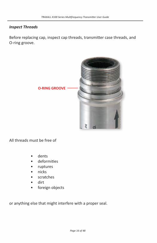
Inspect Threads
Before replacing cap, inspect cap threads, transmitter case threads, and O-ring groove.
All threads must be free of
• dents• deformities• ruptures• nicks• scratches• dirt• foreign objects
or anything else that might interfere with a proper seal.
O-RING GROOVE

Page 17 of 48
TRAXALL X100 Series Multifrequency Transmitter User Guide
* Available from CDI (N1499-70 NITRILE)
Inspect O-Rings
Ensure O-ring is serviceable. A brittle and/or deformed O-ring may not properly seal. If in doubt, replace it.*
Lubricate O-ring with a light coating of high-temperature grease (such as Dow Corning MOLYKOTE® 44)
Carefully replace O-ring over threads and onto its groove.
Page 18 of 48
TRAXALL X100 Series Multifrequency Transmitter User Guide
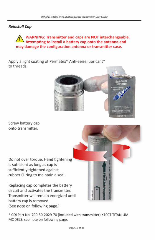
Reinstall Cap
Apply a light coating of Permatex® Anti-Seize lubricant* to threads.
Screw battery cap onto transmitter.
Do not over torque. Hand tightening is sufficient as long as cap is sufficiently tightened against rubber O-ring to maintain a seal.
Replacing cap completes the battery circuit and activates the transmitter. Transmitter will remain energized until battery cap is removed. (See note on following page.) * CDI Part No. 700-50-2029-70 (included with transmitter) X100T TITANIUM MODELS: see note on following page.
WARNING: Transmitter end caps are NOT interchangeable. Attempting to install a battery cap onto the antenna end
may damage the configuration antenna or transmitter case.

Page 19 of 48
TRAXALL X100 Series Multifrequency Transmitter User Guide
X100-2N-RC: Replacing battery cap readies this model for operation, but it draws no battery current until activated by externally-operated ripcord. (see Appendix C, pg. 44)
X100-2N-SWX: Replacing battery cap readies this model for operation, but it draws no battery current until activated by predetermined pipeline pressure (see Appendix C, pg. 42)
When batteries and battery cap are in place
• The transmitter itself will be activated and will stay active for the life of the battery. Removal of battery cap will terminate all transmitter function. • The transmitter will actively seek to establish a communications link for the next five minutes. If communication is not established within five (5) minutes, the transmitter will “time out.”
Should this occur, cycle the power to the transmitter by momentarily removing and replacing battery cap. If you are still unable to establish communication, you may need to replace batteries.
NOTE:
X100-1N, 2N, 3N, 4N, 5N: Replacing cap completes the battery circuit and activates the transmitter. Transmitter will remain energized until battery cap is removed.
NOTE: Do not apply anti-seize lubricant to titanium threads.

Page 20 of 48
TRAXALL X100 Series Multifrequency Transmitter User Guide
* X100-2N-SWX and X100-2N-RC models are factory-configured, therefore have no antenna caps.
5. PREPARE TRANSMITTER FOR CONFIGURATION
NOTE: Transmitter antenna end caps marked as shown have LEFT-HAND threads. Turn CLOCKWISE to remove.
Expose Antenna Unscrew and carefully remove the antenna cap.*

Page 21 of 48
TRAXALL X100 Series Multifrequency Transmitter User Guide
WARNING: Do not attempt to unfold
or otherwise handle the flexible antenna.
Page 22 of 48
TRAXALL X100 Series Multifrequency Transmitter User Guide
6. RUN CONFIGURATOR
MENUOPTIONS
TOOLBAR

Page 23 of 48
TRAXALL X100 Series Multifrequency Transmitter User Guide
MENU OPTIONS
File LoadProfile A profile is a custom XML file containing frequency, mode, and pulse settings. SaveProfileAs...
Once a transmitter is configured, its profile may be stored for re-use, such as reassignment to another transmitter. This can be a time-saver for batch configurations.
Exit Closes the Configurator application View Status Bar Check/uncheck to show Tool Bar Check/uncheck to show FieldLink Connect/Disconnect Controls communication with FieldLink flash drive Refresh Devices* Updates list of transmitters detected by FieldLink Update Firmware** Places FieldLink device into update mode Reset Device Returns FieldLink device to normal operation Help System Info Lists all relevant information about an active transmitter as well as Configurator host PC Help Launches PDF version of this User Guide AboutConfigurator Application software version and build information
TOOL BAR Connect/Disconnect Controls communication with FieldLink flash drive Refresh Devices Updates list of transmitters detected by FieldLink Update Firmware** Places FieldLink device into update mode
*Configurator automatically refreshes every four seconds** Firmware updates are to be performed only at the direction of CDI Technical Support

Page 24 of 48
TRAXALL X100 Series Multifrequency Transmitter User Guide
TRANSMITTER PANE
TRANSMITTERPROFILE PANE
CONFIGURATIONPANE
STATUS BAR
TRANSMITTER INFORMATION AND CONTROL PANES ProfilePane
Indicates serial number, model, firmware, signal strength, battery load, battery chemistry (Alkaline or Lithium), and available voltage of whichever transmitter is actively selected in the Transmitter Pane.
Note Revision, Radio Signal, and Battery Voltage fields are blank when a simulated transmitter is selected.

Page 25 of 48
TRAXALL X100 Series Multifrequency Transmitter User Guide
TransmitterPane Lists all transmitters “seen” by FieldLink. Transmitters are added to this pane as they are detected by FieldLink. FieldLink can list as many as four transmitters at any given time. Green, Red, or Yellow icons indicate transmitter connection state.
Active Transmitter (when highlighted)
Detected Transmitter
Offline or Lost Connection
Invalid Configuration
A “Simulated” transmitter is provided to familiarize you with Configurator. You may change the simulated transmitter to any X-Series model and battery configuration by double-clicking the icon. ConfigurationPane Interactive window with drop-down, radio button, and slider controls. Here you can select a frequency, a constant or pulse operational mode, and examine various range vs. battery life scenarios. A corresponding graph illustrates the range– power relationship. When you have the configuration you want, the Save to Transmitter button will write the configuration to the transmitter memory where it will be stored until changed. Status Bar Text prompt indicating state of Configurator application.
Page 26 of 48
TRAXALL X100 Series Multifrequency Transmitter User Guide
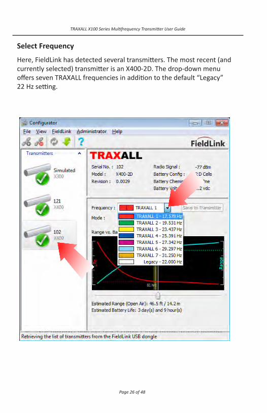
Select Frequency Here, FieldLink has detected several transmitters. The most recent (and currently selected) transmitter is an X400-2D. The drop-down menu offers seven TRAXALL frequencies in addition to the default “Legacy” 22 Hz setting.

Page 27 of 48
TRAXALL X100 Series Multifrequency Transmitter User Guide
Select Mode The default transmission mode is Constant (continual) signal. Selecting Pulse opens a second window showing a pulse pattern. Pulse mode generally results in increased battery life during a run. In addition, customized pulse patterns can provide each pig with a unique electronic signature, useful when running a pig train containing multiple transmitters.
Modify Pulse Mode Moving On Time and Off Time sliders will change the signal pulse:
Page 28 of 48
TRAXALL X100 Series Multifrequency Transmitter User Guide
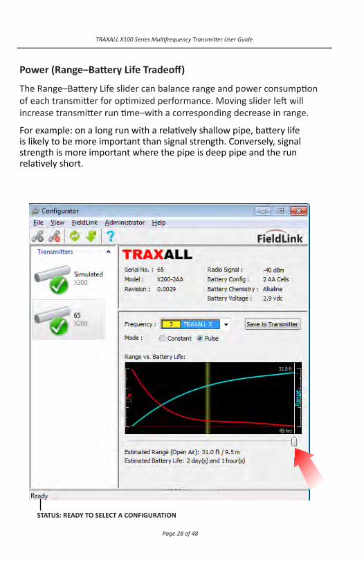
Power (Range–Battery Life Tradeoff) The Range–Battery Life slider can balance range and power consumption of each transmitter for optimized performance. Moving slider left will increase transmitter run time–with a corresponding decrease in range. For example: on a long run with a relatively shallow pipe, battery life is likely to be more important than signal strength. Conversely, signal strength is more important where the pipe is deep pipe and the run relatively short.
STATUS: READY TO SELECT A CONFIGURATION

Page 29 of 48
TRAXALL X100 Series Multifrequency Transmitter User Guide
A fixed yellow line near the center of the range-power graph indicates the estimated optimal balance for the selected transmitter. As you move the slider to this line it will momentarily “snap” in place.
Here, the estimated signal range for this X200-2AA is nearly 30 ft, with an estimated run time of nearly five days.
STATUS: OPTIMAL RANGE/POWER BALANCE FOR THIS TRANSMITTER
Page 30 of 48
TRAXALL X100 Series Multifrequency Transmitter User Guide
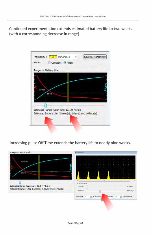
Increasing pulse Off Time extends the battery life to nearly nine weeks.
Continued experimentation extends estimated battery life to two weeks (with a corresponding decrease in range).

Page 31 of 48
TRAXALL X100 Series Multifrequency Transmitter User Guide
Further decreasing Range, decreasing On Pulses, and increasing Off Duration can extend this transmitter’s run time beyond 40 weeks!
Save Settings
When the desired configuration has been determined, select Save to Transmitter button to retain your transmitter settings. These configuration settings are stored in the transmitter flash memory and you may power down by removing batteries until you are ready to place the transmitter into service.
Remember, you may save the profile (see pg. 23) if there is a possibility you will be reusing this configuration on another transmitter.

Page 32 of 48
TRAXALL X100 Series Multifrequency Transmitter User Guide
WARNING: Do not attempt to bend, tuck, fold, or otherwise
handle the flexible antenna.
Replace Antenna Cap
Inspect cap threads, transmitter case threads, O-ring groove, and O-ring as with battery cap (pgs. 16–18) and apply lubricant and anti-seize.
Carefully lower the end cap over the flexible antenna circuitry until cap and transmitter screw threads meet.
WARNING: Transmitter end caps are NOT interchangeable. Attempting to install a battery cap onto the antenna end may damage
the configuration antenna or transmitter case.

Page 33 of 48
TRAXALL X100 Series Multifrequency Transmitter User Guide
Screw antenna end cap onto transmitter. (Observe Left-Hand Thread marking.) Do not over torque. Hand tightening is sufficient as long as cap is sufficiently tightened against rubber O-ring to maintain a seal.
Your transmitter is now ready to be placed into service.

Page 34 of 48
TRAXALL X100 Series Multifrequency Transmitter User Guide
PLACING TRANSMITTER INTO SERVICE
Foam and Plastic Pigs
• Remove plug or bolt • Place transmitter in cavity (either direction) • Replace plug or bolt
Checklist
Before placing a transmitter into service, always make sure:
• Batteries are fresh and of proper size and type.
• Battery polarity is properly observed.
• Serviceable O-rings are installed. Brittle and/or deformed O-rings may not properly seal, thus compromising case Integrity.
• Transmitter case, caps, and cap threads are clean and free of dents, ruptures, or other damage which could compromise the transmitter components.

Page 35 of 48
TRAXALL X100 Series Multifrequency Transmitter User Guide
TROUBLESHOOTING
FieldLink Connection Failure
FieldLink connection failure can be result from obsolete device firmware or a missing or corrupted device driver.
Click Show Details to determine the cause.
FieldLink programming, or firmware, is stored in the device’s flash memory. (Transmitters have their own integral firmware). This error message indicates unsupported or obsolete firmware. FieldLink devices with firmware revision 0.0021 or greater can be updated.
Devices with firmware 0.0020 or older cannot be updated and must be replaced.
Unlike firmware, the FieldLink device driver resides on your PC or laptop.
A new driver may be easily downloaded from the CDI website (www.pigging.com; see. pg. 10)

Page 36 of 48
TRAXALL X100 Series Multifrequency Transmitter User Guide
Transmitter Connection Loss/Failure
This icon indicates a transmitter is offline. This can be the result of a routine shutdown, system timeout, power loss, or RF signal disruption.
Here, for example, the X200-2AA has been powered down after its configuration has been set and batteries removed. As long as the transmitter has been successfully configured, this is no cause for concern. Connection failure can also indicate a system timeout. Upon activation, the transmitter will attempt to establish a communication link.
If communication is not established within five (5) minutes, the transmitter will time out.
Should this occur, cycle the power to the transmitter by momentarily removing and replacing battery cap. If you are still unable to establish communication, you may need to replace batteries.
The RF signal can be disrupted when an antenna cap is prematurely replaced, or by a signal path obstruction such as a structure or vehicle. Signal loss can also occur when a transmitter is moved too far from the Fieldlink device. If this is the case, simply clear the signal path. You may need to cycle power as described above.

Page 37 of 48
TRAXALL X100 Series Multifrequency Transmitter User Guide
WARNING:Always remove batteries before placing the unit
into storage. Failure to do so may result in damage and may void warranty.
WARNING
Always ensure immediate environment is free of explosive gases, liquids, or other substances. Always use caution when opening any CDI transmitter that has been in a pressurized environment.
It is possible for pressurized liquid or gas to leak into a transmitter and remain there even after the transmitter has been removed from the pipeline. For this reason, always point the transmitter away from yourself or others when opening a cover or end cap. As possible for liquids to be present within cap threads, point transmitter downward to drain liquid out of and away from transmitter components or batteries.
REMOVING TRANSMITTER FROM SERVICE
Page 38 of 48
TRAXALL X100 Series Multifrequency Transmitter User Guide
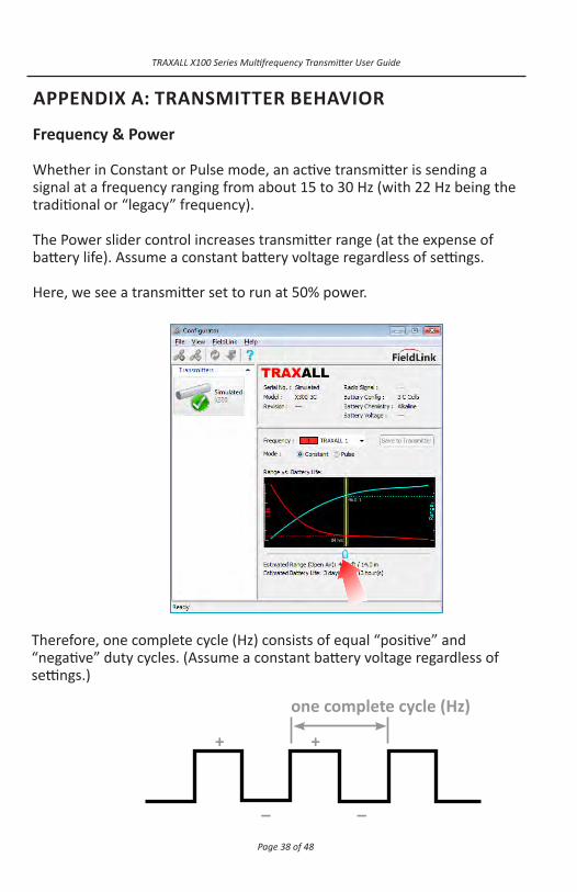
APPENDIX A: TRANSMITTER BEHAVIOR
Frequency & Power
Whether in Constant or Pulse mode, an active transmitter is sending a signal at a frequency ranging from about 15 to 30 Hz (with 22 Hz being the traditional or “legacy” frequency). The Power slider control increases transmitter range (at the expense of battery life). Assume a constant battery voltage regardless of settings.
Here, we see a transmitter set to run at 50% power.
one complete cycle (Hz)
+
–
+
–
Therefore, one complete cycle (Hz) consists of equal “positive” and “negative” duty cycles. (Assume a constant battery voltage regardless of settings.)
Page 39 of 48
TRAXALL X100 Series Multifrequency Transmitter User Guide
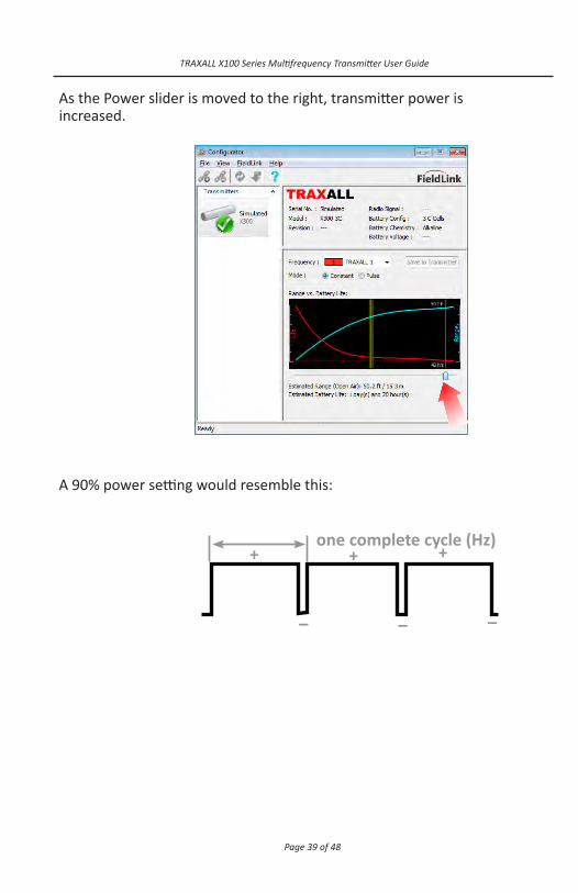
As the Power slider is moved to the right, transmitter power is increased.
–
one complete cycle (Hz)+
–
+
–
+
A 90% power setting would resemble this:

Page 40 of 48
TRAXALL X100 Series Multifrequency Transmitter User Guide
Pulse Characteristics
When Pulse mode is selected, Width and Repeat settings are accessible.They affect duration and spacing of transmitter signals.
ON/OFF Time Width Sets duration of on and off cycles. At On Time Width, transmission occurs. At Off Time Width, there is no transmission.
ON/OFF Pulse Repeat Sets number of on and off cycles to repeat.
ON Time Width
OFF Time Width
ON Time Width
ON Pulse Repeats: 3

Page 41 of 48
TRAXALL X100 Series Multifrequency Transmitter User Guide
APPENDIX B: SYSTEM SPECIFICATIONS
Transmission Type: Electromagnetic Detection Devices: Magnetic Pipeline Pig Location and Tracking Systems, Land-based and Subsea Signaling Systems
External Pressure Rating: 172 bar [2,500 psi] End Cap O-rings: N1499-70 NITRILE
Power: Alkaline N-Cell
Material: 304L Stainless Steel
Resistivity: 0.72
Magnetic Permeability: 1.02
Pipe Line Sizes:
X100-1N 50.8 – 152 mm [2 – 6 in.] X100-2N, 2N-SWX, 2N-RC 50.8 – 203 mm [2 – 8 in.] X100-3N 102 mm [4 in.] and larger X100-4N 152 mm [6 in.] and larger X100-5N 203 mm [8 in.] and larger Pipe Wall Thickness: Up to 38.1 mm [1.5 in.]

Page 42 of 48
TRAXALL X100 Series Multifrequency Transmitter User Guide
APPENDIX C: SPECIALTY APPLICATIONS
X100-2N-SWX
The X100-2N-SWX is a pressure-activated transmitter designed to begin transmission at a preset pipeline pressure.
Pressure activation is useful whenever the precise date of pig deployment is unknown and battery conservation over a long operational period is critical. Transmitter power consumption when switched OFF is zero. Activation pressure is set at the time of manufacture and is documented on the packaging labels and inserts.
Latching/Non-latching Though activation pressure is factory-set, you may set the SWX for either LATCHING or NON-LATCHING modes.
Latching: the transmitter stays on once activation pressure is reached
Non-latching: transmitter ON state follows pipeline pressure; i.e., will turn on or off depending on pressure
Latching mode is set by a dip switch located inside the pressure switch housing. Carefully unscrew the housing and separate far enough apart to gain access to dip switch. NOTE: It is not necessary to disconnect circuit board wiring, but you should avoid undue strain on wiring or connector.
Page 43 of 48
TRAXALL X100 Series Multifrequency Transmitter User Guide
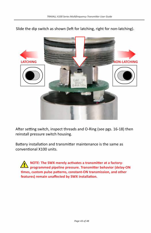
NOTE: The SWX merely activates a transmitter at a factory-programmed pipeline pressure. Transmitter behavior (delay-ON
times, custom pulse patterns, constant-ON transmission, and other features) remain unaffected by SWX installation.
After setting switch, inspect threads and O-Ring (see pgs. 16-18) then reinstall pressure switch housing. Battery installation and transmitter maintenance is the same as conventional X100 units.
Slide the dip switch as shown (left for latching, right for non-latching).
LATCHING NON-LATCHING

Page 44 of 48
TRAXALL X100 Series Multifrequency Transmitter User Guide
APPENDIX C: SPECIALTY APPLICATIONS (CONT.) X100-2N-RC
X100-2N-RC is a manually-activated transmitter designed to begin transmission when its ripcord pin is removed by a pull on its lanyard from outside the pipeline. The lanyard is attached to a special magnetic trigger at the upline end of the transmitter. The other end of the lanyard is usually routed through a special port on a pig launcher and retained outside the pipeline.
This trigger is held in open (OFF) position by a nylon pin. A pig equipped with this transmitter travels a specified distance downline until the slack is taken out of the lanyard (usually by pulling). This breaks the nylon shaft, closing the transmitter’s activation circuit. NOTE: activation is irreversible. Once the X100-2N-RC is activated, it remains ON until transmitter is recovered and battery cap removed at the end of a pig run. Transmitter behavior pressure is set at the time of manufacture and is documented on the packaging labels and inserts. Battery installation and transmitter maintenance is the same as conventional X100 units.

Page 45 of 48
TRAXALL X100 Series Multifrequency Transmitter User Guide
WARRANTY
All equipment sold by Control Devices, Incorporated (CDI) is warranted for a period of one (1) year from the date of shipment to Purchaser, providing the instrument or equipment has not been modified, abused, or used for purposes which it was not designed for.
Batteries, probes, leads, magnets, and other consumables subject to wear are not covered by this warranty. CDI will repair or replace faulty equipment during the warranty period when the cause is a defect arising from faulty design, materials or workmanship.
Making a Warranty Claim
Equipment being considered for warranty repair, or a representative sample thereof, must be returned to CDI at the Purchaser’s expense. The equipment must be accompanied by the Purchaser’s written order* describing the defect(s) and authorizing CDI to invoice the Purchaser for any charges not covered by the warranty.
Upon receipt of the equipment and Purchase Order, CDI will examine the equipment and make a determination of the nature and cause of the defect. If the defect is not covered by the warranty, CDI will quote to Purchaser the cost for replacement or repair equipment, and will not proceed until Purchaser delivers a written acceptance of the quotation.
During the one year warranty, CDI will bear the cost to return units repaired under the warranty back to the Purchaser’s domestic premises. CDI will return units to foreign countries at Purchaser’s expense.
* Contact CDI at 1-800-580-4234, ext 143 for CDI RMA Form FM-03-0089

Page 46 of 48
TRAXALL X100 Series Multifrequency Transmitter User Guide
CARE, MAINTENANCE, AND SERVICING
Equipment designed by CDI is protected against the environment in which it is intended to operate. Much of the equipment is designed for prolonged use in the field without any special maintenance other than routine battery replacements. It is the Purchaser’s responsibility to insure that proper precautions are taken during installation and operation so that weather seals are in place, routine maintenance occurs, etc. Failure to perform these operations nullifies this warranty.
CDI equipment should only be operated by qualified personnel who are familiar with any and all manuals and procedures for said equipment’s operation.
Service and Repairs
Cost for repairs not covered by the warranty or carried out after the warranty period has expired will be charged at the current hourly or set service rate, plus the cost of materials, upon approval by Purchaser.
Equipment for repair must be sent at the Purchaser’s expense and be accompanied by the Purchaser’s written order describing the defect and authorizing CDI to invoice the Purchaser for labor, materials and return delivery cost.
No service or repair will be undertaken until an approved written order is received from the Purchaser.
Operating equipment while in a damaged condition nullifies this warranty.

Page 47 of 48
TRAXALL X100 Series Multifrequency Transmitter User Guide
NOTES

ABOUT CDI
CDI is a family-owned and operated business located in Broken Arrow, Oklahoma, just 12 miles from downtown Tulsa. Incorporated in 1982, CDI has proudly been manufacturing products in the United States for more than 32 years. CDI currently employs 45 people in the areas of electronics and mechanical design, software and firmware programming, electronics manufacture, machining, and more.
All CDI products are designed and built completely in-house utilizing an on-premises machine shop boasting six fully-automated CNC machines as well as full-time electronics assembly personnel.