TECHNICAL REPORT ARCCB-TR-9 1004 · TECHNICAL REPORT ARCCB-TR-9 1004 ... RqEPORT NUMBlER L GOVT...
35
lAD TECHNICAL REPORT ARCCB-TR-9 1004 CONTROLLER AND SOFTWARE rf DEVELOPMENT FOR THE XM9 1 AUTOLOADER 0 N cvo N RONALD L. RACICOT MARY ELLEN BRADY CHARLES COBB DTI LECTE JANUARY 1991 US ARMY ARMAMENT RESEARCH, ADEVELOPMENT AND ENGINEERING CENTER CLOSE COMBAT ARMAMENTS CENTER BEN]iT LABORATORIES WATERVLIET, N.Y. 1.2189-4050 ii APPROVED FOR PUBLIC RELEASE; DISTRIBUTIO2 U4LIMITED 91 3 20 046
Transcript of TECHNICAL REPORT ARCCB-TR-9 1004 · TECHNICAL REPORT ARCCB-TR-9 1004 ... RqEPORT NUMBlER L GOVT...

lAD
TECHNICAL REPORT ARCCB-TR-9 1004
CONTROLLER AND SOFTWARE
rf DEVELOPMENT FOR THE XM9 1 AUTOLOADER0
NcvoN RONALD L. RACICOT
MARY ELLEN BRADY
CHARLES COBB DTILECTE
JANUARY 1991
US ARMY ARMAMENT RESEARCH,ADEVELOPMENT AND ENGINEERING CENTER
CLOSE COMBAT ARMAMENTS CENTERBEN]iT LABORATORIES
WATERVLIET, N.Y. 1.2189-4050
ii
APPROVED FOR PUBLIC RELEASE; DISTRIBUTIO2 U4LIMITED
91 3 20 046

DISCLAIMER
The findings in this report are not to be construed as an official
Department of the Army position Unless so designated by other authorized
documents.
The use of trade name(s) and/or manufacturer(s) does not constitute
an official indorsement or approval.
DESTRUCTION NOTIC
For classified documents, follow the procedures in DoD S200.22-M,
Industrial Security Manual, Section 11-19 or DoD 5200.l-R, Information
Security Program Regulation, Chapter IX.
For unclassified, limited documents, destroy by any method that will
prevent disclosure of contents or reconstruction of the document.
For unclassified, unlimited documents, destroy when the report is
no longer needed. Do not return it to the originator.
sECURITY CLASSIFICATION OF TIS PAGE (Wn, DeN hnemNOREADJ DIETRUCTIONSREPORT DOCUMENTATION PAGE BEFOE COMUPLETIG FORM
1. RqEPORT NUMBlER L GOVT ACCSSION NO. 3. RECIPIENT*S CATALOG NUMBER
ARCCB-TR-91004I
4. TITLE (and Subdue) S. TYPE OF REPORT & PERIOD COVERED
CONTROLLER AND SOFTWARE DEVELOPMENT FOR FinalTHE XK91 AUTOLOADER S. PERFORMING ORG. REPORT NUMBER
7. AUTHOR(4) S. CONTRACT OR GRANT NUMBER(a)
Ronald L. Racicot, Mary Ellen Brady, andCharles Cobb
S. PERFORMING ORGANIZATION NAME AND ADDRESS 10. PROGRAM ELEMENT. PROJECT, TASKAREA A WORK UNIT NUMBERSU.S. Army ARDEC AMCMS No. 6126.23.H210.0
Benet Laboratories, SMCAR-CCB-TL PRON No. 126.2AH20C
Watervliet, NY 12189-4050
11. CONTOLLING oFrcE NAME AND ADDRESS 12. REPORT DATEU.S. Army ARDEC January 1991Close Combat Armaments Center 13. NUMBER OF PAGESPicrtinny Arsenal, NJ 07806-5000 28
14. MONITORING AGENCY NAME & AODRESSif di.omft inm ComU'ollind Offl) IS. SECURITY CLASS. (of this rport)
UNCLASSIFIED
IS.. DECLASSI FICATION/DOWNGRADIN GSCHEDULE
16. DISTRIBUTION STATEMENT (of al. RAspet)
Approved for public release; distribution unlimited.
17. DISTRIBUTION STATEMENT (of the aberact entered in Block 20, It dlfferent 1mm Report)
IS. SUPPLEMENTARY NOTES
19. KEY WORDS (Continue an rovea side if noceem, mid Idont&y by block nuinber)
AutoloaderServocontrolBang-Bang Control
2L A40RACT (Cwthim. m mmmi e N inueaW, M iiitt by Weak umb-)Some of the important aspects of Benet Laboratories controller/softwarepackage developed for the XM91 autoloader are presented and summarized in thisreport. Consideration is given to the transfer of technology from research todevelopment of the servocontrol approach used and to the characteristics andfeatures of the developed software with a discussion of lessons learned. Thecontroller/software package has been used for the overall development andtesting of the mechanical, electrical, and electronic elements that make upthe autoloader.
11 J iPs M EsXomo or INov s1 oLETZ UNCLASSIFIED
SECUM/ITY CLAPICATIOW OF THIS PAGE (Nm De Efnim4e

nCUasTY CLAMPICAYWUN OF THuS WAG £tbm DOM Dd
UECUI CLASUMPICATION OF THIS PA@UtW Date SlAW

TABLE OF CONTENTSPage
INTRODUCTION........................................... 1
CONTROLLER.................................................... 3
Data Acquisition ................................... ........... 56
Servocontrol .................................................. 6
Multitasking of Events ............................................... 19
OTHER SOFTWARE FEATURES................................................. 21
Source Code Written in C............................................. 21
Continuous Updating of Sensor Status .................................. 21
Pull-Down M~enus ..................................................... 22
Malfunction Handling Procedure ........................................ 24
On-Line Processing .................................................. 24
Other User-Friendly Features............ .. .............. ........ 24
REFERENCES ................... *.............................. 26
TABLES
I.. PARTIAL LIST OF AUTOLOADER EVENTS .......................... 3
II. SEQUENCE OF EVENTS FOR SINGLE-STEP LOAD ........................ 4
III. CONTROLLER PARAMETERS FOR THE XM91 AUTOLOADER ....................... 16
LIST OF ILLUSTRATIONS
1. Data acquisition and computer interaction ............................. 5
2. Block diagram of SZC system .. . ....... .. .. .. .. .. . .. ............ 9
3. Phase diagram of SZC system showing typical trajectory ........ 11
4. Typical SZC block . . ... .. .. .. . .... .. . .. . ... ...................... 18s
5. Flow chart for computing N1 N3 or N4 .. ....... ........ ....... . 19
6. Schematic diagram of multitasking of events .............. 20
i

Pace
7. Main display screen for autoloader software ............................ 22
8. Pull-down menus for other command options .............. ...................... 23
£aoesalon ForNTIS QRA&IDTIC TABUnannounced QJustirication
By 4 r
D stiu
on1

INTROOUCTION
The XN91 autoloader was successfully demonstrated 57 times at the U.S. Army
Technology Show held at Aberdeen Proving Ground, MO, from 1 to 4 October 1990.
Each demonstration included both a loading and downloading of a full-length
140-mm dummy round of ammunition in a full-size gun. The demonstrations were
attended by numerous dignitaries from the press, military, Department of
Defense, and Congress.
The successful development and demonstration of the autoloader included
important efforts in design and fabrication of mechanical, electrical, and com-
puter software components and subsystems. This report describes key elements in
the development of the controller/software package, which has been used in the
overall development and testing of the physical autoloader. Descriptions of the
mechanical, electrical, and electronic characteristics of the autoloader are
planned for future reports. In addition, see Reference 1 for a physical
description of the autoloader.
The autoloader controller is embedded in a general software package that
contains a number of other features not directly related to control functions.
First, this report presents a discussion of the main software/hardware elements
that relate directly to control functions. Emphasis is given to the transfer of
technology from research to oavelopment of the servocontrol approach used.
Secondly, some of the interesting and important characteristics of the overall
software package are discussed to provide a summary of lessons learned for
future software development projects.
The remainder of this report is summarized as follows:
CONTROLLER:
Data Acquisition. Real-time digital and analog input/output computer
boards were used in an IBM-compatible PC to communicate with the motors,

encoders, actuators, and sensors.
Servocontrol. Algorithms were developed for servocontrol of the
critical autoloader subsystem which include the rammer mechanism,
telescoping cell, and the 17-cell magazine. The primary approach used
was switching zone control (SZC).
Multitasking of Events. Time slicing was used to run more than one
event at the same time.
OTHER SOFTWARE FEATURES:
Source Code Written in C. C was chosen to prepare all development
software.
Continuous Updatina of Sensor Status. Selected sensors and output com-
mands were updated on the screen continuously to provide the operator
with real-time autoloader status.
Pull-Oown Menus. A pull-down menu approach was chosen for versatility,
speed, and user friendliness.
Malfunction Handling Procedure. A uniform malfunction or error handling
procedure was adopted to standardize corrective actions when failures
occur during autoloader operations.
On-Line Processina. All critical variables and parameters were kept in
an individual file on hard disk; the file can be edited during program
execution.
Other User-Friendly Features. Other software features that facilitate
operations are listed.
The work on software development and applications to the autoloader was
facilitated with the use of the faster 386 chip-based IBM-compatible PC with at
least 1 million bytes of RAM. The faster speed was required for multitasking
2

operations and the larger RAM proved helpful in compiling some of the larger
software modules.
CONTROLLER
Most of the control logic for operating the autoloader is contained in
software. This includes control logic for individual events as well as
sequencing of events to make up more complicated functions such as loading or
unloading a round of ammunition. Table I is a partial list of autoloader events
for which software has been written. A detailed list of subevents for con-
ducting, for example, a single-step load is shown in Table II. Other details
and event lists are given in Reference 2.
TABLE I. PARTIAL LIST OF AUTOLOADER EVENTS
1. Auto Load: KE Round 16. Engage Rearm Supports
2. Auto Load: HEAT Round 17. Round Inventory
3. Manual Mode: Rammer 18. Open Chain Lock
4. Manual Mode: Inner Cell 19. Close Chain Lock
5. Manual Mode: Magazine 20. Move To KE Round
6. Motor Fault Status 21. Move To HEAT Round
7. Special Demo Program 22. Move To Empty Cell
8. Go Home And Reset 23. Move To Specified Cell
9. Open Blast Door 24. Raise Case Catcher
10. Close Blast Door 25. Lower Case Catcher
11. Engage Warhead Supports 26. Open Breech - Fast
12. Release Warhead Supports 27. Open Breech - Slow
13. Grip Ammo Sequence 28. Close Breech
14. Ungrip Ammo and Go Home 29. Open Breech - Positive
15. Check Clock Trigger
3

TABLE 11. SEQUENCE OF EVENTS FOR SINGLE-STEP LOAD
Begin
Inhibit FireSend gun to load angleIf the proper round is not at the ram position
- Release chain lock- Rotate ready magazine to advance desired round
to ram position- Engage chain lock
Check gun at load angleExtend ramhead to cylinder seatRelease ram warhead supportsCheck gun in batteryCheck gun at load angleEngage gun elevation lockInhibit gun elevationEngage low speed valveOpen breech - slowRaise case catcher - slowRelease low speed valveOpen blast doorCheck path clearCheck chamber emptyRam the roundRetract ram head to home position - longClose breechLower case catcherRelease gun elevation lockPermit gun elevationSend gun to target angleClose blast doorRelease chain lockRotate ready magazine to next desired roundPermit fire
End
4

In the remainder of this section, communication between the computer and
the autoloader electronics, servocontrol approach used for operating the motors,
and multitasking requirements for running some events simultaneously are con-
sidered.
Data Acquisition
A short discussion is presented here on how the computer communicates in
real-time with the autoloader electronics. This communication is accomplished
through using data acquisition (DAC) boards that can be installed directly into
a computer expansion compartment. These boards are comprised of integrated cir-
cuitry for sending out or reading in digital (on/off) or analog (continuous
voltage) signals in real-time in response to computer software requests. Figure
1 is a schematic diagram of this interaction. An operator can select events or
functions which can be communicated to the software using, for example, the
keyboard. The software, in turn, interfaces with autoloader electronics and
eventually with the hardware via the DAC boards.
CLOCK(Pulse
OPERATOR - COMPUTER Generator)
(KEYBOARD) - (SOFTWARE) I~Motor Signals
BOARDS Actuator Signals ELECTRONICS
SSensor signals
t ENCODER -Encoder SignalsComputer Input/Output BOARD t t t
Ports 4 1 1
AUTOLOADER:
Motors, Actuators,Encoders, Switches,
Sensors
Figure 1. Data acquisition and computer interaction.
5
The kinds of signals that can be handled include (1) analog voltage outputs
for running servomotors; (2) analog voltage inputs for reading sensors such as
tachometers or thermocouples; (3) digital outputs for turning on or off some
actuators such as solenoids; and (4) digital inputs for reading on/off types of
sensors or switches. Signals from position encoders that monitor angular posi-
tions or distances can be sent to a separate computer board which deciphers the
encoder signals and, in turn, passes the information directly to the computer or
the DAC boards as a digital number. The timing for the entire control process
is accomplished using an external clock or trigger for real-time sequencing.
A set of software functions, called driver functions, was written to handle
input and output of control signals. These functions greatly simplify software
preparation for performing all of the required events. Whenever a signal is to
be sent out or read in, a subroutine is called which reads and/or writes infor-
mation to the DAC boards.
The commercial DAC boards used in the XM91 autoloader were Data Translation
DT2801 and DT2821 and Industrial Computer Source AOB12 and 010216. Our
experience so far indicates that the Industrial Computer Source boards were
easier and faster to use than the Data Translation boards for comparable opera-
tions.
Servocontrol
One of the more important and significant characteristics of the controller
developed for the XM91 autoloader was the use of SZC to operate the four
servomotors. Two motors were for the rammer, one for the telescoping cell, and
one for the 17-cell magazine. Research was previously conducted at Benet
Laboratories to study the usefulness and limitations of SZC in the area of
robotics and flexible systems (refs 3,4). This technology, along with lessons
6

learned in prior applications, was directly transferred to the autoloader
project.
SZC is a nonlinear feedback controller with the following characteristics
(refs 5-8):
1. It is a near-minimum time controller which approaches the bang-bang
minimum time controller in the limit.
2. Peak torques for motors can be specified to prevent excessive loads
and/or saturation problems.
3. An optional maximum velocity can be specified to prevent runaways and
excessive vibrations or motions.
4. It can be made as robust as desired by specifying and accounting for
maximum disturbing forces derived, for example, from sources such as gravity,
time delays, other coupled degrees of freedom, and changing masses.
The SZC approach eliminates the usual problems of overshoot and instability
inherent in high gain linear feedback systems where saturation of motors and/or
amplifiers becomes a problem.
The basis of SZC is the time optimal bang-bang theory where maximum effort
is applied by motors in both negative and positive directions (accelerating and
decelerating phases) to move a mechanism from one state or position to another
in minimum time (refs 5-7). Instead of a switching boundary, as used in the
bang-bang approach, a switching zone is used wherein the torque varies linearly.
Outside this zone, the torque takes on the maximum allowable values as in bang-
bang.
As will be shown shortly, there is a price to pay for the added advantages
and features of SZC over linear feedback control. The price is that more param-
eters are required and need to be calculated or determined empi-ically when
applied to a specific system. However, one of the biggest advantages of
7

applying SZC to the autoloader has been the ability to use the smallest motors
possible along with the least amount of peak and total electrical energy for
specified or required minimal operating times. These advantages are worth
spending a little more effort on parameter determination.
The remainder of this section is divided as follows: theory; derivation of
controller parameters; integrator term for higher accuracy; and software imple-..
mentation.
Theory
The dynamic system, which is comprised of a moving mass and various forces
acting on the mass, is assumed to be a simple second-order system
J R = ud + u (1)
where J = system mass
x = positio of the mass
u a motor force applied to the mass J
ud = disturbing force which includes gravity, friction, coupling
effects, etc.
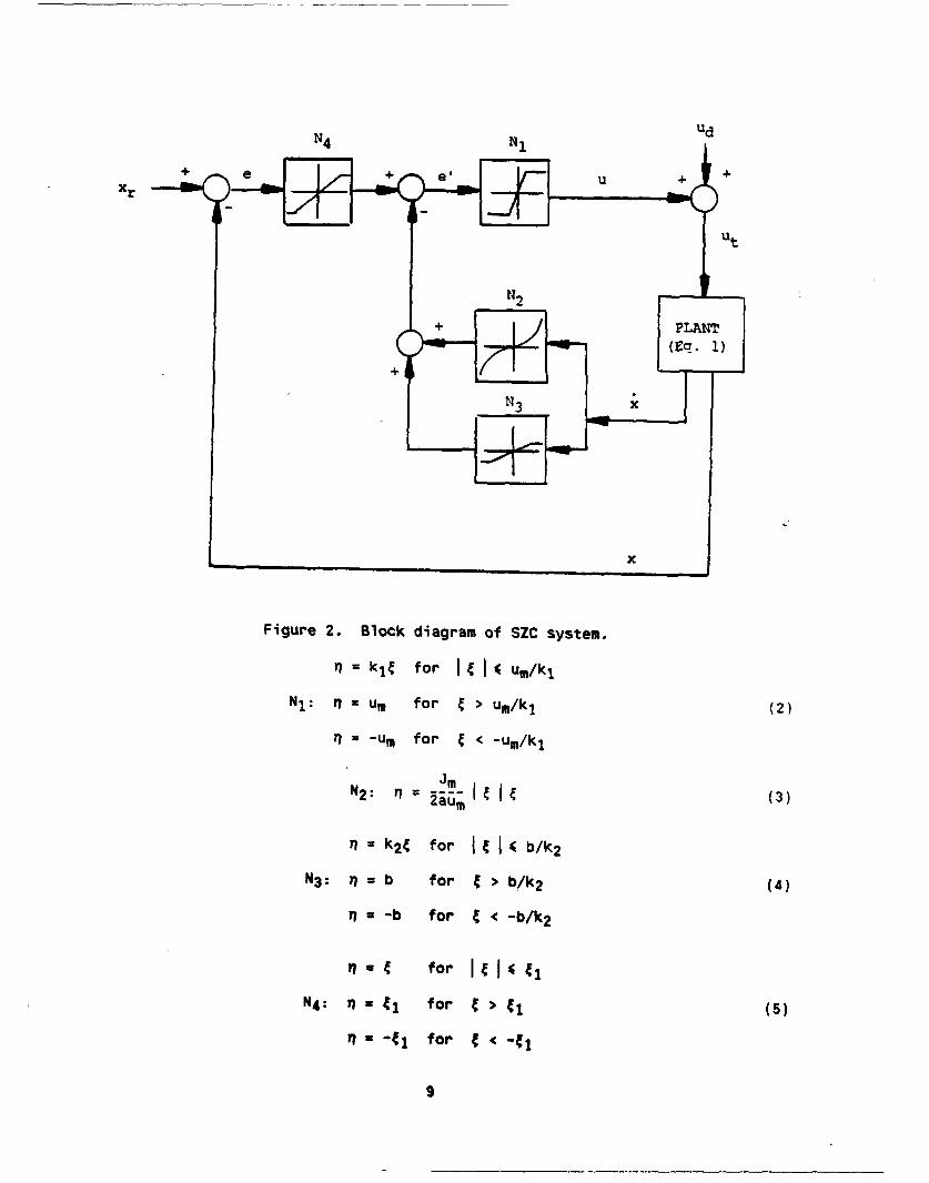
A schematic diagram of the nonlinear switching zone controller is shown in
Figure 2. The theory behind this controller and the derivation of the different
control blocks are given in References 5 through 8. Only the final results are
given in this report.
The 'plant' in Figure 2 is assumed to be the second-order system, Eq. (1).
The variable xr in the figure is the desired reference distance in which the
mass J is to be driven to by the motor forces. The term e is the error term
which is the difference between the desired and actual positions. The nonlinear
blocks NI, N2 , N3 , and N4 are defined as follows ( * input variable, q = output
variable):
8
N4 NiUd
Xr
x
Figure 2. Block diagram of SZC system.
q = k1 t for I( um/kj
NI: q =um* for > um/ki (2)
ni = -um for < c um/ki
N2 : - = (3)
n = k2 4 for if. b/k2NV: n zb for 4 >b/k 2 (4)
Y7 a-b for < -b/k2
n - 4 for t I 41
N4: n - ti for > (5)
-41 for <
9

The constants Jm, um, a, b, kj, k2 , and C1 in Eqs. (2) through (5) are the
controller gains and parameters that need to be specified by the designer.
These constants for the system described by Eq. (1) are defined theoretically as
follows:
Jm = dynamic mass where 'im' denotes the maximum value
um = specified maximum motor force or torque
a = nonlinear function term selected to guarantee sufficient force
for deceleration,
(um-udm)/u m where udm is the maximum value of the disturbance
force ud (6)
b = constant selected to guarantee no overshoot,
= max(um/k1 or k2aumXl/(kl(Xlk2 -1))) (7)
kjk 2 + V(klk 2 )2 - 4klJw h e r e X , = -- -- -- - ( 8 )
2J
kl,k 2 = positional and velocity gains where
k2 ) 2J/k-1 is required for no overshoot when there is no
friction (9)
t1 = b + Jmv2/(2aum) (10)
where C1 is essentially determined from the specified
maximum velocity vm .
The maximum force um can be specified arbitrarily or can be fixed based on
the motor and amplifier specifications. The positional gain k1 is fixed high
and is limited primarily by the requirement for no system chatter or instabil-
ity, which are common effects in pure bang-bang control. Infinite gain k1
reduces the control to switching boundary which is bang-bang.
A better understanding of the SZC characteristics can be obtained by
examining the resulting phase diagram for the second-order system. Figure 3 is
10

a phase diagram plot of x versus x where ud in Ea. (1) is assumed to be zero.
The controller in this case is designed to drive any given nonzero state toward
the origin. The origin is assumed to be the desired new position which gives
xr = 0.0 in Figure 2. For example, if the initial state in Figure 3 starts at
point A, the full maximum force u = um is initially applied. The path then
eventually enters the zone between full negative and positive forces. Once in
the zone, the state is captured and is driven to the origin with little or no
overshoot (see Reference 5 for details). Starting at any other point in the
ohase diagram should also drive the state toward the origin.
A x
Figure 3. Phase diagram of SZC system showing typical trajectory.
Derivation of Controller Parameters
Some experience has been gained in attempting to apply the switching zone
controller described above to actual systems including the XM91 autoloader. A
short discussion is given here describing the procedure developed and used for
11
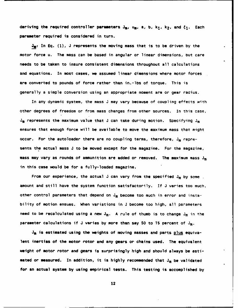
deriving the required controller perameters J, UM, a, b, k1 , k2 , and C1. Each
parameter required is considered in turn.
Jm: In Eq. (1), J represents the moving mass that is to be driven by the
motor force u. The mass can be based in angular or linear dimensions, but care
needs to be taken to insure consistent dimensions throughout all calculations
and equations. In most cases, we assumed linear dimensions where motor forces
are converted to pounds of force rather than in.-lbs of torque. This is
generally a simple conversion using an appropriate moment arm or gear radius.
In any dynamic system, the mass J may vary because of coupling effects with
other degrees of freedom or from mass changes from other sources. In this case,
Jm represents the maximum value that J can take during motion. Specifying Jm
ensures that enough force will be available to move the maximum mass that might
occur. For the autoloader there are no coupling terms, therefore, Jm repre-
sents the actual mass J to be moved except for the magazine. For the magazine,
mass may vary as rounds of ammunition are added or removed. The maximum mass Jm
in this case would be for a fully-loaded magazine.
From our experience, the actual J can vary from the specified Jm by some
amount and still have the system function satisfactorily. If J varies too much,
other control parameters that depend on Jm become too much in error and insta-
bility of motion ensues. When variations in J become too high, all parameters
need to be recalculated using a new Jm. A rule of thumb is to change Jm in the
parameter calculations if J varies by more than say 50 to 75 percent of Jm.
Jm is estimated using the weights of moving masses and parts plus equiva-
lent inertias of the motor rotor and any gears or chains used. The equivalent
weight of motor rotor and gears is surprisingly high and should always be esti-
mated or measured. In addition, it is highly recommended that Jm be validated
for an actual system by using empirical tests. This testing is accomplished by
12

applying a known constant motor force and observing the resulting change in
velocity over a given period of time:
F(force) = Ja = Jdx/dt = JAvelocity/At - J- FAt/Avelocity (11)
A word of caution--in English units, be sure to divide weights by 'g'
(e.g., 386 in./sec2 ) to yield mass J.
um: um is the maximum motor force or equivalent motor torque allowed in
moving the mass J. This maximum force can be derived from motor power and size
requirements if these are to be minimized in a given application or from
reliability and safety requirements where maximum forces need to be limited.
For example, the force used to accelerate a live and relatively fragile round of
ammunition cannot exceed some maximum value. Also, the mechanism itself may not
be able to withstand excessive loads due to potential buckling, wear, or damage
problems. For the autoloader, for example, the rammer boom has a buckling load
when fully extended that should not be exceeded.
!: From Eq. (6), a = (um-udm)/um where udm is the maximum value of the
disturbing force ud in Eq. (1). Disturbing forces are all forces other than the
motor forces and can include gravity, coupling effects, friction, and changing
mass. The numerical value of 'a' is less than or equal to 1.0. This parameter
basically contributes to the robustness of the switching zone controller by
guaranteeing sufficient force for deceleration even in the presence of
disturbing external forces. The disturbing force ud is assumed to be random at
any specific time. It is further assumed that the maximum value that this force
can reach is predictable.
The only disturbing forces that need to be considered in evaluating 'a' are
those that would tend to unexpectedly accelerate the moving mass in the decel-
erating phase of motion and consequently cause overshoot or collisions.
13

Consequently, any disturbing forces that tend to slow down motion, such as fric-
tion, need not be considered.
An excellent example of a disturbing force that can be estimated for the
autoloader is the gravity force when the autoloader is to be operated at dif-
ferent elevations. The elevation of the autoloader at any given time will not
be known, but the worst-case condition can be estimated or specified. This
occurs when loading ammunition at a high negative elevation angle of say -30.0
degrees, which is a specified requirement. In this case, gravity tends to
force the rammer plus the attached ammunition and the telescoping cell to move
faster when loading, resulting in a potentially high overshoot or collision at
the end of the cycle. The additional gravity force in this case can be esti-
mated
Udm = weight * sine(30 degrees)
This equation gives the udm that is used in the equation for 'a'. Other similar
types of forces need to be calculated or estimated and used in the estimation of
'a'.
b and k2 : The parameters b and k2 are required to define the control block
N3 in Figure 2. The primary purpose of this block is to provide velocity feed-
back, and hence damping, near the reference endpoint xr in order to prevent
overshoot. The constant 'b' provides a horizontal shift of the decelerating
trajectory away from the vertical axis in the phase diagram. This shift -allows
the velocity feedback term to become active soon enough with enough decelerating
torque available to prevent overshoot. Away from the endpoint, the block N3
does not take an active control role.
In calculating 'b', Eq. (7) is applied directly. The velocity gain k2
requires special care since too high a value can cause chattering, unstable, or
unsmooth motions near the endpoint. Using Eq. (9) to calculate k2 gives too
14

high a value because of the presence of friction. Generally, k2 is first esti-
mated from Eq. (9) and then is reduced empirically by running the system until
smooth motion is achieved near the command endpoint. For the autoloader, for
example, it was necessary to reduce the theoretical values of k2 by factors of
about 0.5 to 0.6 for the cell and rammer and by a factor of 0.1 for the maga-
zine. For the magazine, very high friction nearly negates the need for a veloc-
ity feedback term to prevent overshoot.
kj: k, is one of the more important parameters to be determined insofar as
providing smooth and stable overall motions are concerned for a given system.
k1 is essentially a positional gain. A useful approach to determine this oaram-
eter is to write it in terms of the maximum specified force um
k, = um/dele (12)
In this equation, dele is an estimate of the half-width of the switching zone
shown in Figure 3. If the system is at rest, for example, dele is the minimum
error distance e = xr - x at which the maximum force um will be applied to
drive the system from its current position x to the desired reference position
xr. For 'e' less than dele, the motor force will be proportionately less than
the maximum value.
The variable dele can also be considered as a measure of the positioning
accuracy. In general, the smaller the value of dele, the more accurate will be
the final endpoint position. If dele goes to zero, the controller reduces to
infinite k1 which gives pure bang-bang control as discussed earlier. If dele
becomes too small, however, unstable and chattering motion will be experienced.
This parameter, therefore, needs to be determined empirically by running the
mechanical system and finding the smallest value of dele for which the motion is
smooth and satisfactory. For the autoloader, this procedure yielded dele values
of about 1 to 2 inches.
1s

!_: The parameter C, is simply determined from Eq. (10) and depends
directly on the specified value for maximum velocity vm . If C1 is very large
(e.g., infinity), then there is no velocity restriction and the system can con-
tinue to increase in velocity until motor saturation is reached. Motor satura-
tion may be desirable for minimizing operation cycle times if excessive motions
and vibrations are not experienced as a result. For the autoloader, velocity
restrictions were found to be necessary for all functions concerned to limit
excessive motions.
Table III lists a typical set of parameter values used to successfully
operate the XM91 autoloader.
TABLE III. CONTROLLER PARAMETERS FOR THE XM9 AUTOLOADER
Parameter Rammer Cell Maaazine
Jm 0.207 lbs/in./secz 0.376 lbs/in./secz 3.886 lbs/in./sec2
um 75.0 lbs 200.0 lbs 500.0 lbs
a 0.85 0.85 1.0
b 2.0 in. 1.0 in. 1.0 in.
ki 37.5 lbs/in. 100.0 lbs/in. 500.0 lbs/in.
k2 0.074 in./in./sec 0.086 in./in./sec 0.018 in./in./sec
t1 25.4 in. 25.9 in. 3.4 in.
vm 120.0 in./sec 150.0 in./sec 25.0 in./sec
Intearator Term for Hiaher Accuracy
The SZC depicted in Figure 2 has a serious limitation for systems with high
friction as is the case for the autoloader: relatively low positional accuracy.
Low accuracy is not necessarily a problem for cases where a mechanism is driven
up against a hard stop and some small collision velocity is tolerable or
16

required. This is the case when operating the rammer and telescoping cell where
some finite endpoint velocity is required to properly seat the round in the gun
tube and to dock the cell against the breech face. In this case, the target
reference point can be set at some value beyond the hard stop.
For the case of the magazine, however, increased positional accuracy was
required and could not be achieved with SZC alone. A satisfactory solution to
this problem was to use an integrator term near the desired endpoint.
Essentially, another block, N5 , is added right after block N4 in Figure 2. N5
is defined as follows ({ = input and n = output):
N n = 0 for IC cN = KI J t dt otherwise
(13)ti
where c is some distance from the endpoint within which the integrator term
becomes active, t1 is the starting time that this happens, and KI is the
integrator gain constant. For the autoloader magazine, c was set at 0.5 inch
and KI at 15.0 inches. Block N5 for this case is evaluated numerically in soft-
ware.
The variable g in Eq. (13) is essentially the eiror term e = (xr-x). If
there is a positive error, the term N5 results in the motor torque being grad-
ually increased with time t driving the system toward the desired endpoint xr.
Once the endpoint xr is reached, the integrator term N5 is zeroed out, ano t1 is
reinitialized to the current time. This zeroing out of the integrator term
accounts for overshoot, if any. Some oscillation may be experienced about the
endpoint if very high accuracy is required. For some set of KI values, which
can be determined empirically, acceptable positioning accuracy can be achieved
in this manner in most cases. For the magazine, a value of KI equal to 15.0 was
found to be satisfactory.
17

Software Implementation
Implementing SZC in software is relatively straightforward. Block N2 in
Figure 2 is determined by mathematically computing Eq. (3). Blocks N1, N3, and
N4 are all computationally similar. Each of these blocks can be defined sym-
bolically by Figure 4. In this figure
= input into the block
= output from the block
nm = maximum allowable absolute value of the outout q
K = gain or slope within the linearly varying zone
= maximum absolute value of t corresoonding to nm
= JIm/K
nm
Slope /K
Figure 4. Typical SZC block.
Figure 5 is the computational flow chart for the case shown in Figure 4
which can be directly implemented into software.
Is

In (input
Figure 5. Flow chart for computing block N1, N3, or N4.
Multitaskina of Events
Time slicing is used to run more than one event at the same time and is
accomplished through the use of a clock (pulse generator) that generates trigger
voltage pulses at a fixed sampling rate. For the autoloader, for example, we
used a sampling rate of 100 cycles per second which gives a sample time interval
(time slice) of 10 milliseconds (0.010 second). The occurrence of a trigger
pulse can be determined in software by continuously monitoring the appropriate
DAC channel in real-time until a voltage pulse is detected. As soon as a
trigger pulse Is detected, a number of different software subroutines are called
in sequence, each of which runs one event and performs one time increment worth
of work per call. After the last event subroutine is called, control is
returned to the beginning to await the next trigger pulse. This process is
19

repeated until all required events have been completed. Figure 6 i3 a schematic
diagram showing this sequence of operations.
CLOCKVoltage PulseEvery At sec(e.g., 0.010)
SOFTWARE
Wait For AITrigger Pulse
Special Function for I_Each EventI _ _ _ _
EVENT CONTROL iVENT II
i I ANO j" i EVENT 2j
SEQUENCER I EVENTiJ
I 1. I
Has Too Much Time . __Elapsed or Malfunc- YES Stop All Events,tion Occurred? Inform Operator,
I Leave ProgramNOi
L------------SE~NO Are All Events YES[ Complete? FINISHED I
Figure 6. Schematic diagram of multitasking of events.
Each event subroutine in the multitasking moue needs to be written in such
a way that it performs its task in an efficient and timely manner. Sensors need
to be read and voltages or digital signals sent out to operate motors and
actuators. If the task is completed, the calling software program is informed,
and the subroutine for the completed task is deactivated. The sum total of com-
puter time required for all simultaneous events must be less than the sample
time interval allowed. The sample time interval should be chosen to assure that
all required events will indeed take place.
20

OTHER SOFTWARE FEATURES
The software package developed for testing and operating the autoloader
contained a number of features other than those directly related to control
functions. Some of the more significant and interesting characteristics of this
software are presented here to provide a summary of lessons learned for future
software development projects. These items proved to be very useful and will be
used in other research and development work.
Source Code Written in C
The C programming language was chosen to prepare all development software.
It is a widely accepted language for applications using personal computers and
has all the capabilities necessary for writing real-time control software.
Large libraries of tested subroutines and extensive software support are readily
available in the open literature and in the open market, and a sizeable number
of experienced C programmers are available to help write software. Equally
important, efficient modern-day compilers and debuggers such as Turbo C simplify
code preparation for large multimodule programs.
Continuous Updating of Sensor Status
When the autoloader software is first activated by the computer operator,
the information displayed on the console screen is as shown in Figure 7. This
display contains four main windows, each of which has a specific puroose: (1)
COMMANDS: used for choosing various commands to perform different functions or
events; (2) DATA I/O: used for entering some data when required and for
displaying messages and help prompts as the software runs; (3) COMMAND STATUS:
displays some of the current command output signals; and (4) SENSOR STATUS:
displays the real-time status of a number of selected sensors.
21

AUTOLOADER TEST STAND --- RAMMER/INNER CELL/NAGAZINE
COMMANDS: COMMAND STATUS:F1 RAMMER/CELL FUNCTIONS RAMMER: MAIN VOLTAGE -0.000F2 MAGAZINE FUNCTIONS DRUM VOLTAGE -0.000F3 GUN FUNCTIONS INNER CELL: VOLTAGE -0.000MANUAL MODE: I RAMMER MAGAZINE: VOLTAGE -0.000
2 INNER CELL3 MAGAZINE SENSOR STATUS:
AUTO LOAD: 4 KE ROUND RAMMER POSITION 3.66355 HEAT ROUND AT HOME? NO
AUTO UNLOAD 6 MAIN MOTOR FAULT OK7 INPUT/OUTPUT REQUEST DRUM MOTOR FAULT OK8 MOTOR FAULT STATUS CELL POSITION 0.02809 SPECIAL DEMO PROGRAM AT HOME? YES
EXIT PRESS ESC EXTENDED? NOMOTOR FAULT OK
DATA I/0: BLAST DOOR: OPENWARHEAD SUPPORT: RETRACTEDRAM GRIPPER MECH: CLOSEDMAGAZINE: POSITION 6.00
CHAIN LOCK CLOSEDREARM SUPPORT: NEUTRAL
Figure 7. Main display screen for autoloader software.
The continuous updating and display of COMMAND and SENSOR STATUS proved to
be extremely helpful for monitoring the current real-time conditions of the
autoloader and for pinpointing malfunctions and potential safety haiards. In
addition to that shown in the SENSOR STATUS window of Figure 7, other sensors
were continuously monitored and if a fail condition arose, a warning message
would be automatically written to the DATA I/0 window. This additional checking
of sensors also proved very helpful.
Pull-Down Menus
Choosing which function or command to execute was simplified through the
use of pull-down menus. Pull-down menus are a convenient means of offering a
large number of easy to use options to the operator. In the computer display
22

shown in Figure 7, the COMMANDS window offers some initial options. The com-
mands written on any'line in this window can be selected for execution in two
ways. First, a colored or highlighted bar can be moved up or down to any line
in the COMMANDS window by using the up and down arrow keys. Pressing the
"ENTER" key executes the highlighted command. Second, simply pressing the
designated key shown on one of the command lines executes that command directly
no matter where the highlighted bar happens to be. In Figure 7, for example,
these keys are F1, F2, F3, and the numbers I through 9.
Some of the more often used autoloader functions are shown in the initial
COMMANDS menu of Figure 7: automatic loading of a round of ammunition,
unloading, manual operations, a special demonstration program and overall
input/output functions. Pressing the Fl, F2, or F3 keys pulls down other com-
mand windows for more options as shown in Figure 8. Commands are chosen from
these other menus in the same manner as in the initial window.
F2 MAGAZINE FUNCTIONS
MAGAZINE FUNCTIONS:
1 ROUND INVENTORY2 OPEN CHAIN LOCK3 CLOSE CHAIN LOCK4 MOVE TO KE ROUND
F1 RAMMER/CELL FUNCTIONS 5 MOVE TO HEAT ROUNDRAM/CELL FUNCTIONS: 6 MOVE TO EMPTY CELL
I GO HOME AND RESET 7 MOVE TO SPECIFIED CELL2 OPEN BLAST DOOR EXIT PRESS ESC3 CLOSE BLAST DOOR4 ENGAGE WARHEAD SUPPORTS5 RELEASE WARHEAD SUPPORTS
6 GRIP AMMO SEQUENCE7 UNGRIP AMMO AND GO HOME F3 GUN FUNCTIONS8 CHECK CLOCK TRIGGER GUN COMMANDS:9 ENGAGE REARM SUPPORTS 1 RAISE CASE CATCHER
EXIT PRESS ESC 2 LOWER CASE CATCHER3 OPEN BREECH - FAST4 OPEN BREECH - SLOW5 CLOSE BREECH6 OPEN BREECH - POSITIVE
EXIT PRESS ESC
Figure 8. Pull-down menus for other command options.
23

Malfunction Handlina Procedure
A uniform malfunction or error handling procedure was adopted for standard-
izing corrective actions when failures occur during autoloader operations. All
event subroutines were written with self-checking and monitoring capabilities to
detect failures. Whenever a critical failure occurs during execution, a stand-
ard function is called which immediately shuts down all autoloader motors and
actuators. In some cases, emergency braking is applied to prevent collisions.
A message is then printed to the DATA I/O window explaining the malfunction.
Execution is then returned to the calling program with an error code set so that
no other functions will be inadvertently called. This error handling procedure
proved invaluable and worked extremely well during our development testing.
On-Line Processing
Another convenient feature programmed into the software was the capability
of performing input and output editing functions without leaving the currently
executing program. All critical variables and parameters were kept in an indi-
vidual file on hard disk which could be edited during program execution. In
conducting a test, then, if one or more parameters needed to be varied to deter-
mine their effect on the functioning of some event, this could be done quickly
and efficiently without leaving the executing program to change the input file
or recompiling the entire program. Also, output data generated during the
running of an event such as loading a round, could be viewed immediately and
edited if necessary, for example, to add other observations and stored for later
printing.
Other User-Friendly Features
Other features programmed into the autoloader software that proved helpful
are listed as follows:
24

1. On-screen DATA I/O window for messages and for inputing some data.
2. Some on-line help messages.
3. Prompts for the next step to be taken by operator in running some
sequential events or if a mistake is made.
4. Two-key inputs required for confirming the continuation of critical
operations (i.e., ctrl + g) to prevent accidental keystrokes causing an unwanted
or unsafe event.
5. Reserving the ESC (escape) key for leaving all active functions or
programs.
26

REFERENCES
1. John Kehn, Lee Bennett, Susan Chainyk, Stephen Krupski, and Douglas Olcott,
"Mechanical Description of a Ready-Round Autoloader," Benet Laboratories
Internal Report BITR 90-5, Benet Laboratories, Watervliet, NY, October 4,990.
2. "Final Test Plan for Laboratory Simulation Testing of the 120-mm XM91
Autoloader System," MTI Technical Report 89TR26, Mechanical Technology,
Inc., Latham, NY, May 1990.
3. R.L. Racicot and S.S.L. Chang, "Switching Zone Control for a System with an
Elastic Joint," U.S. Army ARDEC Technical Report ARCCB-TR-89006, Benet
Laboratories, Watervliet, NY, March 1989.
4. R.L. Racicot and S.S.L. Chang, "Switching Zone Control as a Distributed
Controller," U.S. Army ARDEC Technical Report ARCCB-TR-89010, Benet
Laboratories, Watervliet, NY, April 1989.
5. Z. Xia and S.S.L. Chang, "A Simple Robust Nonlinear Controller," in: Recent
Trends in Robotics, (M. Jamshidi, J.Y.S. Luh, and M. Shahinpoor, eds.),
North-Holland, New York, 1986, pp. 317-328.
6. S.S.L. Chang, Synthesis of Optimum Control Systems, McGraw-Hill, New York,
1961, Chapter 9.
7. J.S. Jeng, "Nonlinear Feedback Control Synthesis for Robotic Manipulator,"
Ph.D. Thesis, State University of New York at Stony Brook, Electrical
Engineering Department, Stony Brook, NY, 1988.
8. H. Asada and J.J.E. Slotine, Robot Analysis and Control, John Wiley & Sons,
Now York, 1986.
26

TECHNICAL REPORT INTERNAL DISTRIBUTION LIST
NO. OFCOPIES
CHIEF, DEVELOPMENT ENGINEERING DIVISIONATTN: SMCAR-CCB-O 1
-DA 1-DC 1-0I -OP 1-OR 1-OS (SYSTEMS) 1
CHIEF, ENGINEERING SUPPORT DIVISIONATTN: SMCAR-CCB-S
-SE 1
CHIEF, RESEARCH DIVISIONATTN: SMCAR-CCB-R 2
-RA 1-RE 1-RM 1-RP 1-RT 1
TECHNICAL LIBRARY 5ATTN: SMCAR-CCB-TL
TECHNICAL PUBLICATIONS & EDITING SECTION 3ATTN: SMCAR-CCB-TL
DIRECTOR, OPERATIONS DIRECTORATE 1ATTN: SNCWV-OD
DIRECTOR, PROCUREMENT DIRECTORATE 1ATTN: SMCWV-PP
DIRECTOR, PRODUCT ASSURANCE DIRECTORATE 1ATTN: SMCWV-QA
NOTE: PLEASE NOTIFY DIRECTOR, BENET LABORATORIES, ATTN: SMCAR-CCB-TL, OFANY ADDRESS CHANGES.

TECHNICAL REPORT EXTERNAL DISTRIBUTION LIST
NO. OF NO. OFCOPIES COPIES
ASST SEC OF THE ARMY COMMANDERRESEARCH AND DEVELOPMENT ROCK ISLAND ARSENALATTN: DEPT FOR SCI AND TECH 1 ATTN: SMCRI-ENMTHE PENTAGON ROCK ISLAND, IL 61299-5000WASHINGTON, D.C. 20310-0103
DIRECTORADMINISTRATOR US ARMY INDUSTRIAL BASE ENGR ACTVDEFENSE TECHNICAL INFO CENTER ATTN: AMXIB-PATTN: DTIC-FDAC 12 ROCK ISLAND, IL 61299-7260CAMERON STATIONALEXANDRIA, VA 22304-6145 COMMANDER
US ARMY TANK-AUTMV R&D COMMANDCOMMANDER ATTN: AMSTA-DDL (TECH LIB)US ARMY ARDEC WARREN, MI 48397-5000ATTN: SMCAR-AEE 1
SMCAR-AES, BLDG. 321 1 COMMANDERSMCAR-AET-O, BLDG. 351N 1 US MILITARY ACADEMYSMCAR-CC 1 ATTN: DEPARTMENT OF MECHANICSSMCAR-CCP-A 1 WEST POINT, NY 10996-1792SMCAR-FSA 1SMCAR-FSM-E 1 US ARMY MISSILE COMMANDSMCAR-FSS-D, BLDG. 94 1 REDSTONE SCIENTIFIC INFO CTR 2SMCAR-IMI-I (STINFO) BLDG. 59 2 ATTN: DOCUMENTS SECT, BLDG. 4484
PICATINNY ARSENAL, NJ 07806-5000 REDSTONE ARSENAL, AL 35898-5241
DIRECTOR COMMANDERUS ARMY BALLISTIC RESEARCH LABORATORY US ARMY FGN SCIENCE AND TECH CTRATTN: SLCBR-DD-T, BLDG. 305 1 ATTN: DRXST-SDABERDEEN PROVING GROUND, MD 21005-5066 220 7TH STREET, N.E.
CHARLOTTESVILLE, VA 22901DIRECTORUS ARMY MATERIEL SYSTEMS ANALYSIS ACTV COMMANDERATTN: AMXSY-MP 1 US ARMY LABCOMABERDEEN PROVING GROUND, MD 21005-5071 MATERIALS TECHNOLOGY LAB
ATTN: SLCMT-IML (TECH LIB) 2COMMANDER WATERTOWN, MA 02172-0001HQ, AMCCOMATTN: ANSMC-IMP-L 1ROCK ISLAND, IL 61299-6000
NOTE: PLEASE NOTIFY COMMANDER, ARMAMENT RESEARCH, DEVELOPMENT, AND ENGINEERINGCENTER, US ARMY AMCCOM, ATTN: BENET LABORATORIES, SMCAR-CCB-TL,WATERVLIET, NY 12189-4050, OF ANY ADDRESS CHANGES.

TECHNICAL REPORT EXTERNAL DISTRIBUTION LIST (CONT'D)
NO. OF NO. OFCOPIES COPIES
COMMANDER COMMANDERUS ARMY LABCOM, ISA AIR FORCE ARMAMENT LABORATORYATTN: SLCIS-IM-TL 1 ATTN: AFATL/MN2800 POWDER MILL ROAD EGLIN AFB, FL 32542-5434ADELPHI, MD 20783-1145
COMMANDERCOMMANDER AIR FORCE ARMAMENT LABORATORYUS ARMY RESEARCH OFFICE ATTN: AFATL/MNFATTN: CHIEF, IPO 1 EGLIN AFB, FL 32542-5434P.O. BOX 12211RESEARCH TRIANGLE PARK, NC 27709-2211 METALS AND CERAMICS INFO CTR
BATTELLE COLUMBUS DIVISIONDIRECTOR 505 KING AVENUEUS NAVAL RESEARCH LAB COLUMBUS, OH 43201-2693ATTN: MATERIALS SCI & TECH DIVISION 1
CODE 26-27 (DOC LIB) 1WASHINGTON, D.C. 20375
DIRECTORUS ARMY BALLISTIC RESEARCH LABORATORYATTN: SLCBR-IB-M (DR. BRUCE BURNS) 1ABERDEEN PROVING GROUND, MO 21005-6066
NOTE: PLEASE NOTIFY COMMANDER, ARMAMENT RESEARCH, DEVELOPMENT, AND ENGINEERINGCENTER, US ARMY AMCCOM, ATTN: BENET LABORATORIES, SMCAR-CCB-TL,WATERVLIET, NY 12189-4050, OF ANY ADDRESS CHANGES.