
AD-A256 065 - Defense Technical Information Center 065 ad technical report arccb-tr-92034 eddy...
45
AD-A256 065 AD TECHNICAL REPORT ARCCB-TR-92034 EDDY CURRENT INSPECTION OF GUN TUBES DTIC ELECTE A iJ DAVID CONCORDIA JULY 1992 US ARMY ARMAMENT RESEARCHP DEVELOPMENT AND ENGINEERING CENTER CLOSE COMBAT ARMAMENTS CENTER BENET LABORATORIES WATERVLIET, N.Y. 12189-4050 APPROVED FOR PUBLIC RELEASE; DISTRIBUTION UNLIMITED j 7 •92-26566
Transcript of AD-A256 065 - Defense Technical Information Center 065 ad technical report arccb-tr-92034 eddy...

AD-A256 065
AD
TECHNICAL REPORT ARCCB-TR-92034
EDDY CURRENT INSPECTION OF GUN TUBES
DTICELECTE
A iJ DAVID CONCORDIA
JULY 1992
US ARMY ARMAMENT RESEARCHPDEVELOPMENT AND ENGINEERING CENTER
CLOSE COMBAT ARMAMENTS CENTERBENET LABORATORIES
WATERVLIET, N.Y. 12189-4050
APPROVED FOR PUBLIC RELEASE; DISTRIBUTION UNLIMITED
j 7 •92-26566

DISCLAIMER
The findings in this report are not to be construed as an official
Department of the Army position umless so designated by other authorized
documents.
The use of trade name(s) and/or manufacturer(s) does not constitute
an official indorsement or approval.
DESTRUCTI ON NOTI CE
For classified documents, follow the procedures in DoD 5200.22-M,
Industrial Security Manual, Section 11-19 or DoD 5200.1-R, Information
Security Program Regulation, Chapter IX.
For unclassified, limited documents, destroy by any method that will
prevent disclosure of contents or reconstruction of the document.
For unclassified, unlimited documents, destroy when the report is
no longer needed. Do not return it to the originator.
Form ApprovedREPORT DOCUMENTATION PAGE I OMB No. 0704-0188
"iPlic reportin burden for this collection of information is estimated to average I hour bar response. including the time for reviewing instructions. searchring existing data sources.gathering and maintaining the data needed. and completing and reviewing the collection of information. Send comments regarding this burden estimate or any other asoect of thisCollfor reducing tis burden. to Washington remaauars Services. directorate ofr information Operations and Reports. 1215 ietfersonOavs$ghwa. Suite 1204. Arlington. VA 22202-4302. and the Office of Management and Budget. Paperwork Reduction Project (0704,0188), Washington. DC 20503.
1. AGENCY USE ONLY (Leave blank) 2. REPORT DATE 3. REPORT TYPE AND DATES COVERED
4. TITLE AND SUBTITLE S. FUNDING NUMBERS
EDDY CURRENT INSPECTION OF GUN TUBESAMCMS: 665808.E860035PRON: M74F193803M71A
6. AUTHOR(S)
David Concordia
7. PERFORMING ORGANIZATION NAME(S) AND AOORESS(ES) 8. PERFORMING ORGANIZATIONREPORT NUMBER
U.S. Army ARDECBenet Laboratories ARCCB-TR-92034Watervliet. NY 12189-4050
9. SPONSORING/MONITORING AGENCY NAME(S) AND ADDRESS(ES) 10. SPONSORING/ MONITORINGAGENCY REPORT NUMBER
U.S. Army ARDECClose Combat Armaments CenterPicatinny Arsenal. NJ 07806-5000
11. SUPPLEMENTARY NOTES
12a. DISTRIBUTION/ AVAILABILITY STATEMENT 12b. DISTRIBUTION CODE
Approved for public release; distribution unlimited
13. ABSTRACT (Maximum 200 words)
This report describes the work done by the author to develop an eddy current system to inspect the inside diameter surface ofgun tubes.
The report begins by explaining the basic theory of eddy current inspection. Next. the experimental work, which was done totest the feasibility of using this test method for gun tube inspection, is described. Finally, the system. which was developed asa result of this experimental work, is described in detail.
The system is capable of automatically performing inside diameter surface inspection of a gun tube in less than five minutesand is currently being tested as a replacement for the pre-swage magnetic particle inspectiou of gun tubes.
14. SUBJECT TERMS 15. NUMBER Oi- PAGESEddy Current Inspection. Nondestructive Testing, Gun Tube Inspection 39
16. PRICE CODE
17. SECURITY CLASSIFICATION 18. SECURITY CLASSIFICATION 19. SECURITY CLASSIFICATION 20. LIMITATION OF ABSTRACTOF REPORT OF THIS PAGE OF ABSTRACT
NSN 7S40-01-280-5500 Standard Form 298 (Rev 2-89)Prescribed by ANSi Sid Z39-18298-102

TABLE OF CONTENTS
ACKNOW LEDGEMENTS ......................................................... iii
O BJE CTIV E .................................................................... 1
BACKGROUND AND INTRODUCTION ............................................ 1
A PPRO A CH .................................................................... 2
RE SU LT S ...................................................................... 3
CO N CLU SIO N .................................................................. 6
EPILO G U E .................................................................... 6
A PPEND IX A .................................................................. 27
A PPEN D IX B .................................................................. 29
List of Illustrations
1. Basics of eddy current inspection ................................................... 7
2. Pencil probe .................................................................. 8
3. Eddy current test setup with pencil probe ............................................ 9
4a. Recording signal from a 105-mm section containing three quench cracks ................... 10
4b. Recording signal from a 105-mm section with a heavily-scaled surface without quench cracks .... 10
5. Recording signals from a 105-mm section containing three quench cracks ................... 11
6. Effects of filtering on signals ..................................................... 12
7. Comparison of crack and scale signals at different crack depths ........................... 13
8. Three quench cracks on a rough surface ............................................ 14
9a. Eddy current inspection system .................................................. 15
9b. Gun tube supported by adjustable stands ........................................... 16
10. Probe assem bly .............................................................. 17
11. Strip-chart recorder and eddy current instrument ..................................... 18
12a. Recording from a 120-mm tube containing numerous quench cracks and no scalepockets using the Magnetic Analysis System ........................................ 19

12b. Recording from a 120-mm tube with scale pockets and no quench cracks using
the M agnetic Analysis System .................................................. 19
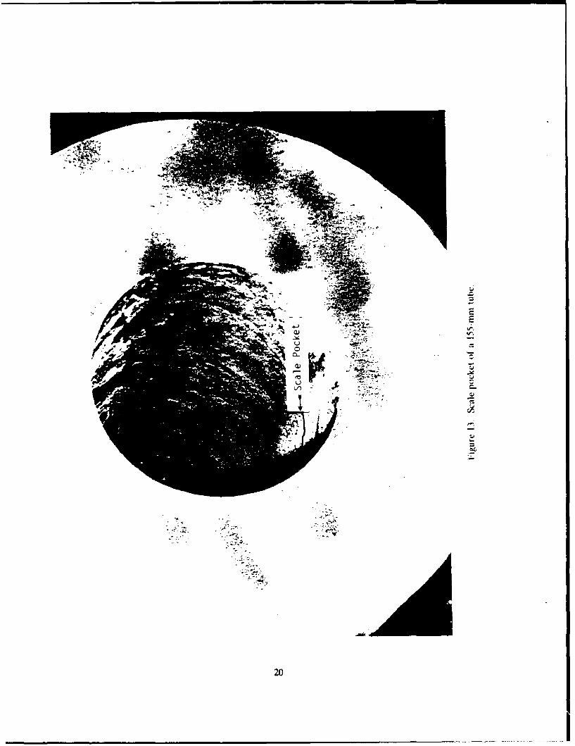
13. Scale pocket of a 155-mm tube .................................................. 20
14. Signals obtained from quench cracks digitized at 10,000 Hz ............................. 21
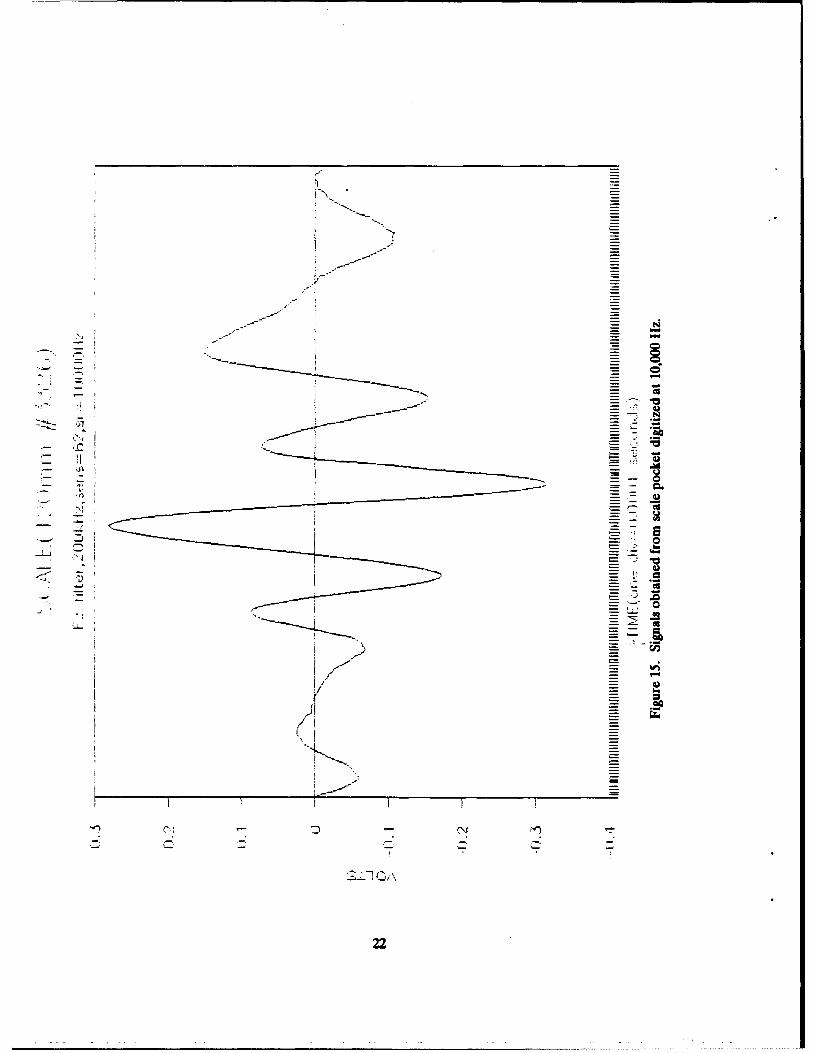
15. Signals obtained from scale pocket digitized at 10,000 Hz .............................. 22
16. Effect of tube rotation on crack indication using the distance-compensated probe ............ 23
17. Surface ride probe ............................................................ 24
18. Test results using the surface ride probe on a 105-mm tube ............................. 25
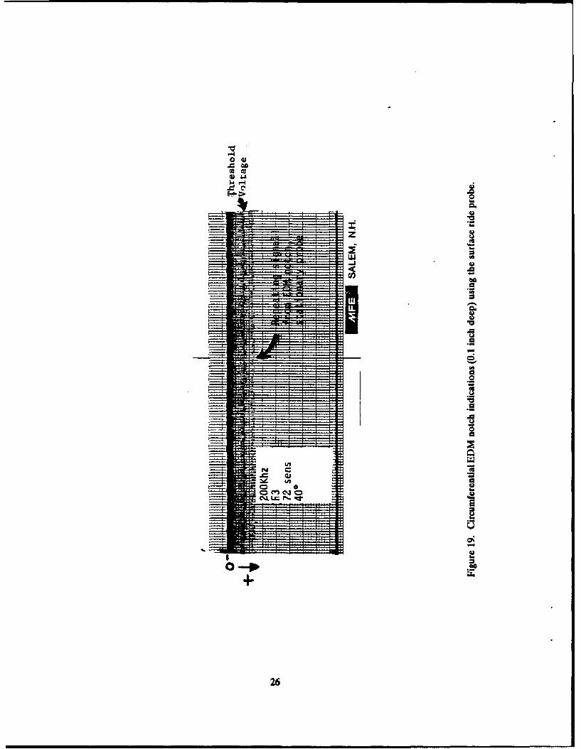
19. Circumferential EDM notch indications (0.1 inch deep) using the surface ride probe .......... 26
fi

ACKNOWLEDGEMENTS
The author would like to acknowledge the contributions of the following people from BenetLaboratories:
Mr. William Sullivan for his expertise in electrical engineering and his moral support; Mr. JohnAtchinson for his expertise in the area of nondestructive testing; and Mr. John Moss for designing themechanical modifications to the system.
In addition, the assistance of many other individuals, too numerous to mention here, whocontributed to the success of this project is greatly appreciated.
JI ,T~f:: , - - -'
iii

OBJECTIVE
Traditionally, inside diameter (ID) inspection of gun tubes is done using a fluorescent magneticparticle solution with a black light borescope. The inspection, which takes approximately 30 minutes pertube, has four major limitations:
1. Because the inspection is manual, it is possible that an inspector could fail to inspect theentire tube surface.
2. The determination of a defect relies on the interpretation of an inspector.
3. The process is fatiguing to an inspector.
4. No permanent record is automatically produced indicating the defect locations.
The objective of this project was to develop a system that would eliminate the four problemsencountered with magnetic particle borescope inspection. An additional objective was to reduce the timerequired to inspect the II) surface of a gun tube.
BACKGROUND AND INTRODUCTION
Of the various methods of nondestructive testing available, eddy current testing most appropriatelymeets the objectives of this project. It is an easily-automated process and a rapid means of inspection.One limitation of eddy current testing is that it is basically a surface inspection. Because of this, defectsthat do not come to the ID surface cannot be located. However, this is not a serious limitation for guntube inspection, since the type of defect encountered after heat treatment is usually a quench crack, which,in most cases, comes to the ID surface.
The principle behind eddy current inspection is depicted in Figure 1. The oscillator represents theelectronics used to produce an AC voltage across the coil at a given frequency. "I" represents the electriccurrent flowing in the coil at one instant in time. The current in the coil produces a magnetic field, thestrength of which is proportional to the number of coil turns (N) multiplied by the current. The magneticfield produced by the current is shown in Figure 1 by the arrow labeled H1 (magnetic field strength of thecoil). This creates a magnetic flux that causes currents to flow in the test material located adjacent to thecoil. These currents, because of their tendency to flow in a circular path, are called eddy currents and areproduced by magnetic induction. The eddy currents flowing in the material labeled 'E' produce a magneticfield counter to the original magnetic field. As shown in Figure 1, since the magnetic flux is a function ofthe voltage (E), frequency (f), and number of coil turns only, then the magnetic field strength of the coilmust increase to maintain the flux. The increase in magnetic field strength is produced by an increase inthe current. A crack in the test material decreases the magnitude of the eddy current, because the currentmust now travel around the crack resulting in a decrease in the magnetic field strength of the eddy currentand the magnetic field strength of the coil current. The decrease in the magnetic field strength of the coilis produced by a decrease in the value of the current in the coil. The decrease or change in the currentcan be readily measured and is a way to detect cracks in the test material. The depth to which the eddycurrents penetrate the test material is shown in Figure 1. Since the depth is inversely proportional to therelative permeability of the material, the currents do not penetrate nearly as deep in steel as they do in anonmagnetic material such as aluminum. Thus, eddy current inspection of magnetic materials is basicallya surface inspection.
Because this is essentially a surface inspection, there is one potential problem when inspecting anas-forged tube. The surface condition of an as-forged tube can be rough due to loose scale breaking awayand leaving an irregular surface. However, since the ID surface is inspected after the tube is machined, if
1

it could not be used effectively on the as-forged tube, it could replace the magnetic particle inspection on
a rough-machined tube prior to swage.
APPROACH
The initial effort of this project was to modify an eddy current inspection system (Reluxtrol)previously purchased. The Reluxtrol was designed to locate ID defects. It uses an eddy current sensingcoil slightly smaller than the tube's ID. The sensing coil is mounted at the end of an assembly with anelectric motor to drive the coil down the tube bore. The system was modified in an attempt to overcomeproblems previously discovered. These problems were operation at a frequency that was too high andpoor impedance matching of the sensing coil with the driving circuit. To eliminate these problems, alower range frequency module was purchased, and the number of coil turns was changed to match thedriving circuit impedance.
Tests were conducted using the modified system on production gun tubes and on sample sectionsof tubes that contained quench cracks. According to these tests, the system was not sensitive enough tolocate quench cracks. The type of sensing coil used produced eddy currents that circulated around thecircumference of the ID surface. The change in impedance produced by a quench crack was not enoughto cause a significant chaage in the signal. Additional problems were encountered with the drive system.including slippage between the drive belts and the tube surface and failure of the drive belts.
To improve the sensitivity, tests were conducted using a small "pencil"-type probe (see Figure 2)using the setup shown in Figure 3. A pencil probe was mounted adjacent to the ID surface of a section ofa gun tube. The section of tube was rotated by a motor to produce relative motion between the probe andtest surface. The Reluxtrol instrument was used to process the signal from the sensing probe.
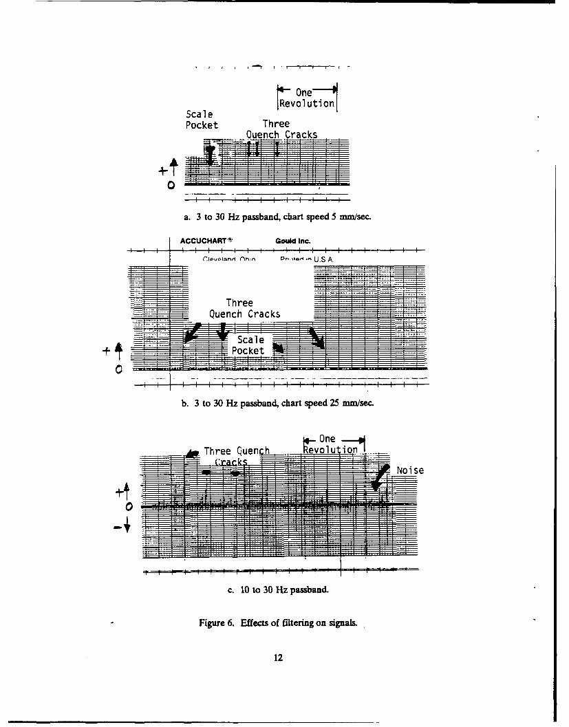
The test results were encouraging. Figure 4a shows the recording from a 105-mm tube sectioncontaining three quench cracks: one large crack and two smaller cracks. Figure 4b shows the recordingfrom a 105-mm section with a heavily-scaled ID surface without quench cracks. Both recordings weretaken at 100 kHz, 20 mV/division, and a passband filter setting of 10 to 30 Hz. The probe was held fixedas the sample rotated. The recording in Figure 4a shows two closely-spaced quench cracks and a largerquench crack approximately 180 degrees from the smaller ones. Figures 5a through 5c show recordingsobtained at three different frequencies: 250, 100, and 30 kHz. As seen, the change in frequency had nosignificant effect on the signal. Figure 6 demonstrates the effect of filtering on the signal produced.Figure 6a shows the signal produced from a section containing three quench cracks and a scale pocketapproximately 0.5 inch in diameter formed when an area of scale separated from the ID surface. Thepocket depth is approximately 0.035 inch, and the quench cracks are from 0.1 to 0.5 inch deep. Filteringwas set at 3 to 30 Hz passband. The signals in Figures 6a and 6b have been rectified and clipped for amore legible recording. Figure 6b shows the same recording at an increased chart speed to differentiatethe wavelength between the quench crack and the scale pocket signal. Figure 6c shows the recording at apassband filter setting of 10 to 30 Hz. The indication from the scale pocket was filtered out. The resultsof these tests were encouraging at the time, since they indicated that filtering would effectively remove theunwanted indications from scale pockets on the recorder trace.
Figure 7 shows the recorder trace from a tube section containing four quench cracks and one scalepocket. In this case, the difference in amplitude between the signal produced from a 0.5 and a 0.2-inchdeep quench crack can be seen. Althougn the amplitude of the signal is not directly proportional to thecrack depth, a deeper crack did produce a larger amplitude signal. Figure 8 shows the results of a testconducted using a section containing three quench cracks. The remaining surface was rough due toscaling. Despite the noise signal produced from the rough-scaled surface, the signal-to-noise ratio was stillvery good.
2

As a result of the tests conducted using the pencil probe, the following was concluded.
0 The frequency was not an important factor in determining the quality of signal produced in the30 to 250-kHz range. Tests conducted below 30 kHz showed a deterioration of the signal-to-noise ratio.
* Filtering effectively reduced the signal produced from surface roughness.
* The pencil probe produced a signal far superior than that from the full diameter coil.
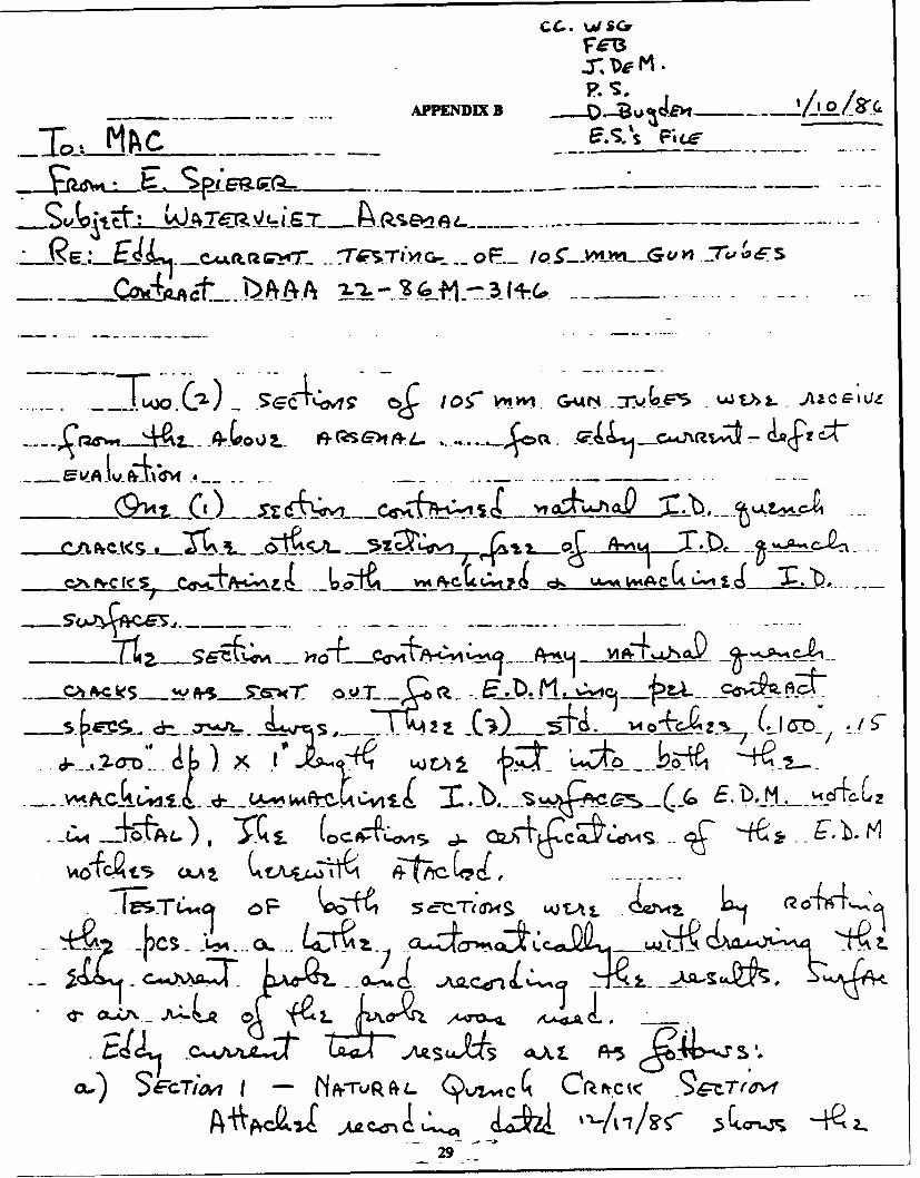
Further testing was conducted by two eddy current system manufacturers on sample sections ofgun tube material containing quench cracks. They were asked to determine if eddy current was a practicalmethod of locating quench cracks in as-forged gun tube material. The results are given in Appendices Aand B. Both contractors, using a pencil probe, found that eddy current was an effective method oflocating quench cracks.
The results of the work accomplished up to this point were used as the basis to develop aspecification for the purchase of an automated eddy current inspection system. The system was requiredto have the following features:
"* An oscilloscope display of the eddy current signal.
"* A strip-chart recorder.
"* The ability to detect defects as small as 0.00(1 inch wide, 0.1 inch deep, and 0.5 inch long. (Thesystem purchased can detect defects as small as 0.1 inch long.)
"* The ability to inspect each tube in five minutes or less.
"* A rotating sensor mounted on a mandrel driven by a motor external to the probe assembly.
RESULTS
The automated eddy current inspection system (Magnetic Analysis) is shown in Figures 9a and 9b.Figure 9a shows the system with the control panel in the center of the photograph. Figure 9b shows a guntube supported by adjustable stands located at the end of the mandrel assembly. The probe assembly ismounted on the end of a mandrel driven into and out of the tube bore by an electric motor. The probe,located near the middle of the probe assembly (see Figure 10), spins at 600 rpm to provide relative motionbeteen the tube surface and probe. Mandrel translational speed is adjustable within 1 to 10 inches persecond. The signal readout is given on a strip-chart recorder (see Figure 11). Channel one gives the eddycurrent signal, and channel two indicates whenever channel one exceeds a threshold value. The thresholdvalue is set at a minimum defect depth, so that channel two is triggered whenever the preset value isexceeded.
The instrument can operate at 200, 400, or 600 kHz, with six different filter bands available. Italso incorporates electronics that can amplify signals above a preset value and attenuate signals below apreset value. This feature further enhances the signal-to-noise ratio, and thus produces a clearerindication whenever a defect is detected. A phase control is used to select the proper signal phase angleto enhance the signal from a crack.
The varying ID and the out-of-roundness of the as-forged gun tubes necessitate incorporatingcircuitry to compensate for the variation in spacing between the probe and the tube surface. Thecompensation circuit operates in the 0.015 to 0.150-inch range. The compensation circuitry essentially
3

works to electronically maintain the amplitude of the signal produced from a defect at a constant levelwithin the given range based on the signal from a sensor located adjacent to the eddy current sensor.
The eddy current sensor is adjustable to provide the proper air gap for use with the 105-mm, 120-mm, and 155-mm gun tubes. The operation is automated via a programmable controller. The inspectionis initiated by positioning a gun tube onto stands, with the muzzle end of the tube butted against the endof the machine (see Figure 9b). When the operator presses the cycle start button, the probe is driven intothe gun tube and reverses direction after traveling a programmed distance (220 inches for the 105-mmM68 tube). On the return path, the signal from the eddy current sensor is processed and recorded.Inspection time for the 105-mm M68 tube is less than four minutes per tube.
Tests conducted with the Magnetic Analysis System on as-forged gun tubes demonstrated that thesystem can effectively locate quench cracks. However, tubes containing areas on the surface from whichscale has separated can produce false indications.
Figure 12a shows the recorder trace obtained from the inspection of a 120-mm tube. The uppertrace (channel one) is the signal from the eddy current sensor, and the bottom trace (channel two) istriggered whenever the amplitude of channel one exceeds the threshold value. This tube containednumerous quench cracks located from the breech end to six feet away. In this case, the signal obtainedfrom the quench cracks is quite obvious. This tube, although in the as-forged state, has an ID surfacewithout loose scale. Figure 12b shows the trace obtained from a 155-mm tube without quench cracks, butit did have an ID surface with loose scale on the breech end of the tube. The indication from scalepockets (see Figure 13) is indistinguishable from the quench crack indications.
In an attempt to examine the signals more closely, those obtained from quench cracks and scalepockets were digitized at a sampling rate of 10,000 Hz. The results are shown in Figures 14 and 15,respectively. Unfortunately, this closer examination of the signals did not reveal a discernible differencebetween the two signals. At that point, a decision was made to concentrate on preparing the system toinspect tubes after rough-machining in the before-swage condition. Tubes in this condition have amachined ID surface, therefore the problem of scale pockets encountered with the surface condition on as-forged tubes would not be present. Further attempts to develop methods capable of discriminatingbetween scale pocket and defect signals require funding and efforts in excess of this project.
Tests were conducted on five different 105-mm M68 tubes in the before-swage conditioncontaining bore defects. Each tube had quench cracks that were previously identified using magneticparticle inspection. These tests were conducted to determine optimum settings for the eddy currentsystem. The following settings were used:
Frequency 400 kHzFilter F2Phase 15 degreesVertical enhancement inSensitivity 60Reverse speed I inch/second
The varying air gap between the sensor and the material surface (within the 0.015 to 0.150-inchrange) was compensated for by an electronic circuit. However, the compensation affected the amplitudeof the signal only. At 200 kHz, there was a sufficient phase shift produced by the air gap variation to ruleout using this frequency. At 400 kHz, the phase shift was minimal within the compensation range. Therewas a desire to use the lowest frequency possible to increase the penetration of eddy current within thematerial. Thus, 400 kHz was used rather than 600 kHz, despite the fact that both produced a minimalphase shift within the compensation range:
4

The F2 filter setting corresponds to a band-pass of 13 to 160 Hz. This setting produced the leastattenuation of the quench crack signal. The 15-degree phase setting was selected to pi*oduce the maximumdefect signal. Despite the minimum phase shift produced at 400 kHz between the defect and noise signals,the signal-to-noise ratio was still in excess of 5 to 1 at this phase setting. The vertical enhancement featureprovides a decrease of any signal below unity gain and an increase of any signal above unity gain, both in alogarithmic fashion. Therefore, this feature artificially increases the signal-to-noise ratio. The sensitivitysetting was based on the tests conducted on tubes containing previously identified defects. The minimumsetting was used that would trigger channel two of the recorder when the sensor was positioned over thesmallest defect identified using magnetic particle inspection. In other words, the sensitivity setting wasselected to ensure that the eddy current inspection would indicate a defect at every location that themagnetic particle inspection indicated a defect.
The tests conducted on rough-machined tubes using the distance-compensated probe revealed aproblem, namely, that the compensation provided by the electronic circuit is nonlinear. The probeassembly tends to sit closest to the bottom surface of the gun tube due to its own weight. This produces avariation in distance between the sensor and the tube surface as the sensor rotates. The nonlineardistance compensation results in an amplitude response when a crack is encountered that depends on howthe tube has been placed on the supports. Figure 16 shows two results from tests on a 105-mm tubecontaining quench cracks. In Figure 16a the quench crack indications near the center of the recording arelarge enough in magnitude to trigger the threshold channei, which indicates defects are present. Figure16b shows the recording obtained with the tube rotated 180 degrees from its position in Figure 16a. Thischange in amplitude is a result of the nonlinear response of the compensation circuit.
A new sensor design, the surface ride probe, was tested to eliminate the need for the distance-compensated circuit. The sensor, shown in Figure 17, uses "shoes" that ride on the surface of the testmaterial. The "shoes" are designed to hold the eddy current strnsor coil at a fixed standoff distance(approximately 0.030 inch) from the test material. A test using a 105-mm tube (S.N. 2664) is shown inFigure 18. The upper trace shows the eddy current indications obtained from quench cracks that existedon the ID surface of the tube from 90 to 135 inches from the breech end. The lower trace is the thresholdchannel, indicating that the threshold voltage has been exceeded. The fixed-distance contact sensoreliminated the problem of varying response when the tube was rotated. Also, the signal-to-noise ratio wassomewhat better than with the distance-compensated probe. The following settings were used:
Frequency 200 kHzFilter F3 (30 to 263 Hz)Phase 250 degreesVertical enhancement outSensitivity 65Reverse speed 1 inch/second
Since all the tests conducted up to this point were with tubes containing longitudinal quenchcracks, i.e., cracks parallel to the long axis of the tube, additional tests were conducted on a tube segmentwith a circumferential slot. The slot was produced using electrical discharge machining (EDM) andmeasured 0.1 inch deep, 1.0 inch long, and approximately 0.01 inch wide. Results of the tests are shown inFigure 19. This figure shows the signal obtained with the rotating sensing coil positioned over the EDMnotch. The trace represents a repeating signal obtained each time the sensing coil passes over the notch.The signal level obtained exceeded the threshold value, indicating that a circumferential defect can bedetected with this eddy current system if the coil passes over the end of the defect. The signal obtainedoccurred as the sensor passed the end of the EDM notch. The eddy current sensor requires the change insurface-to-probe distance to produce a detectable signal.
5

Two characteristics of the surface ride probe were observed during testing, which althoughundesirable, would not limit its use as an inspection tool. One characteristic is the false signal producedwhen the sensor is riding on a tapered surface. This occurs on the rough tubes at the lead-in angle of thebreech end. However, the tapered section is ultimately removed from the tube. The signal is producedbecause the taper allows the sensor to come closer to the test material than on the constant diametersurface. The second characteristic is a tendency to produce a false signal due to metal filings producedafter repeated inspections with the surface ride probe. In normal use, this would not occur, since falsesignals were not produced until approximately 50 test runs were completed on the same tube. It does,however, indicate the need to have a clean ID surface before the eddy current inspection.
As with any operation in which there is metal-to-metal contact, some wear of the "shoe" materialwas encountered. After 75 tube inspections, the amount of wear measured approximately 0.002 inch. Theshoe material used was tool steel, with a hardness of 62 Rc. Curiently, a sensor with a titanium carbidecoating is being tested. Thus far, it has been used to inspect over 100 tubes without showing measurablewear.
Presently, the automated eddy current inspection system is being used concurrently with magneticparticle to inspect production 120-mam M256 rough-machined gun tubes. Thus far, the two inspectionmethods have been in agreement except for two tubes in which the eddy current system detecteddiscontinuities that were not found during magnetic particle inspection. In both cases, when examinedusing a white light borescope, the discontinuities were judged to be tool marks. This demonstrates thehigh degree of sensitivity obtainable with eddy current inspection. Early on in the inspection of 120-mmtubes, some false indications were produced during eddy current inspection due to interference from thehoning solution, which remains on the bore surface after the tube is honed. This has necessitated cleaningof the tube's bore surface prior to the eddy current inspection.
CONCLUSION
In its modified form, the eddy current inspection system can effectively and reliably locate IDsurface defects, such as quench cracks, on rough-machined gun tubes. Thl. inspection time is less thanfour minutes for a 105-mm M68 tube and less than five minutes for a 120-mm M256 tube. Automation ofthe inspection process eliminates the possibility of failing to inspect a section of the tube, the effect ofinspector fatigue, and the need for interpretation by the inspector. The use of a strip-chart recorderprovides a permanent record of the inspection. Work is in progress to computerize the inspection results.A computer could provide more detailed information than the strip-chart recorder, such as clock positionof the defect, and it would eliminate the need to store paper romcordings.
EPILOGUE
A method to distinguish between the defect and scale pocket signals is presently beinginvestigated. The use of artificial intelligence has been proposed, whereby an aigorithm would examinenumerous examples of defect and scale pocket signals so that it could "learn" to tell the difference betweenthe two types. Another area to investigate is the use of filtering to eliminate the scale signal discussed inthis report. Filterin•, was effective during preliminary testing. It is possible that the use of a filter with asmaller band-pass would effectively reduce the scale pocket signal. The possibility of incorporating adescaling operation before inspection is also being considered. Descaling would not only allow eddycurrent inspection before the rough-machining operation, but it would also help the machining operationby reducing tool wear and machine maintenance.
6

H -NI
SMAX ERMS
- FluxE - Voltage
........... ...... f - Frequency........... N - Number of Turns
- Depth of Penetration..............::p-Resistivity..............................
Relaive.ermebiliy........~******f. -- Freqency
Fi........ .... Bsc.fedycret npci
........ * ......... 7

4v0

c2)
40
Ln.

Figure 4a. Recording signal from a 105-mm section containing three quench cracks.
4~ One ___,
Figure 4b. Recording signal from a 105-mm section with a heavily-scaled surface without quench cracks.
10

a. 250 kHz signal.
%evo ut Io
b. 100 kHz signal.
3~44
c. 30 kllz signal.
Figure 5. Recording signals from a 105-mm section containing three quench tracks.
11
OneAScale Revolultion
Pocket Three
Qu nc I I I I I
a. 3 to 30 Hz passband, chart speed 5 nmm/sec.
ACCUCHARTS' Gould Inc.
Cr.1PvPI~nn1 (Ohrn 01'. 1- . U.S.A.
b. 3 to 30 Hz passband, chart speed 25 mm/sec.
Figree 6.Efect of fiterigonsinals
12

Four
Quench Cracks
0.5" deep crack:
0.2" deep crack'
- :I~~~~ m I
Figure 7. Comparison of crack and scale signals at different crack depths. Chart has beenmagnified (5X) to show the difference between the magnitude of signals fromdifferent crack depths.
13

LLM-AMI~ I LL1 L1-1
f i t I I I
4j CI f I I [-
>'
CU,
I I It
06
I T T TI I I-LI LA-rý b
-1 rI 11.a
I t I
14

C
£
C
C
C
15

16

17)

_. it-i
18

20"
Relative;y sm-othsurface.
MIA:
Quench CracksI ".. . (Numerous indicatio
alc:ng 23' of tube&i• i:, {]i!•Threshold
Channel
Figure 12a. Recording from a 120-mm tube containing numerous quench cracks and no scalepockets using the Magnetic Analysis System.
... Signal from scale: pocket (numernus
- -. locations).
74t Threshold
Channel
Figure 12b. Recording from a 120-mm tube with scale pockets and no quench cracks usingthe Magnetic Analysis System.
19
22
rs�
-'-4'-
* -.- A
20
I

f0
ca
lj.
I'
....-... S--% = "a
-- -
-21
N, --
I -
21
N
0
- F a
C.- 0
a- -� CI h.
* -.-- 0* a
� *-)
U.. -L - -- a
I,-. _
Uh.
If a
F-., - -
�J2 C,
22

-4::
. .. Crack signals ~
a.
7T..-~Decreased signal
from cracks as a..tube 180* from positi
-
l1Tin A
TV! 44. 2' 41 Q
SALEM, N.H. U.S.A.
b.
Figure 16. Effect of tube rotation on crack indication using the distance-conmpensated probe.
23

IOf
24

r H:
zrz
WA0
Usa
L47
be0
U , :0to
-
ua.
Lu0
250
0I-0..0
I-
zI-
w a0
aU,a0..00
U.2
U,a.2
a
U0a
a0I..0
UI..
0a
0-* a04.
26

Hi ENISCHEL INSIRUMEN IS, AP11AIM FCW TEST FMANARBOR, MICHIGAN AP-N..~ 0S5,71
APPENDIX A TEST NO,____
CUSTCM kut-''\ =A DUE .______PART I Se-r4ýoii 0P 105 r M6 G~ -T-~ei PERS(ONU: 0.-YOWBUETIVE:________________ CBX'D B! _____
-Tes + te+-Lp
00,a~t.
00JI )0 <N
Ll 0.05
27

*~i~ ~4jL. ,i AL1j~$ ?dPJI.IhCA=C~S PRFE'r TEST FORMAlANN ARBOR, MICiGAIN A?-MO. 71~~
TEST NO._____
.CUSTCM t 1~~. %;,4 ks-v,.^G DATE _ ___
PART 2 s-4ea%S, Ns -V, MqG= Tu4es PERSONNEL: o 7f.-vOBJECTIVE: crtmic.-. v +sý; CKI'D B1I _____
4Katvt MA-Spti I%
10 0VIIse
pRQpo.se~ SYNC.tl
'SYNC. S:9grni)
II _ 36e?- .
28
C4. %d SGrFee3
APPENDEX B L_ _ _
_05_ "m Gum -- r:.. -A -G u
T~T1 14 A"!-
CC~~4A3~-3 ~ __ ---
C.E 4 o1,~11 GA4 .I~1..ACL.
~r~a,,A~ q.~ 1 j 2. ~ . ... ~ -dz s
Us.;ts.±4~ dcf hr
M-~af ucn"LJ 5- 7/..
29

-~~~~ -2-14~LP~L~
-Mt0_ "-d
o I+41a --
- pr~~ V - _Y"L-^*kVVl.-
_~~~~~AC &- o__ .. ~ ._ -.- -
-~~r 0 ~~sz_
Ž1(5 E____
7e T 4-% co 7 ,,- .
~~U av I.S~ ~EC~A -- -----. ~---30

j s a-4. tw-A.'._J
-~ ~ ~ Elf ___c-o -o
31

a-o
'CI
oc
4.0 w
"C 11
C) >9 a : 0
L.) LA a. c< -
oo >1
LO t
C'.D
LX
'a., C)C -- 0C-i C C) CQ coa
I -z - DC-D CJ Iý CD.. 0 C )
LA Ct0%C O -ýO
OL.J -W
cgOft Lai ' 0. " " "0 "L C ', O'0
La.I'.O32

.LL
cic
-- H 77- -
-- -7- 7 7
-_7_
7:1~
_ *777 -.
_-33

L9-
-LLL
h~lu
17 .~ _ _
34i~

j7---
r!y
-3
* ~~~-d,---S
LIZ' -Zt! _ýk
zr-li--
* .- OL-J
~ PALL ý7
~H'~ii~yI

rA '~JC777.
Lii77
-1
I- ~ 457
Fj
L2- I t.
ý l - : 1

TECHNICAL REPORT INTERNAL DISTRIBUTION LIST
NO. OFCOPIES
CHIEF, DEVELOPMENT ENGINEERING DIVISIONATTN: SMCAR-CCB-DA 1
-DC 1-DI 1-DR 1-OS (SYSTEMS) 1
CHIEF, ENGINEERING SUPPORT DIVISIONATTN: SMCAR-CCB-S 1
-So 1-SE 1
CHIEF, RESEARCH DIVISIONATTN: SMCAR-CCB-R 2
-RA 1-RE 1-RM 1-RP 1-RT 1
TECHNICAL LIBRARY 5ATTN: SMCAR-CCB-TL
TECHNICAL PUBLICATIONS & EDITING SECTION 3ATTN: SMCAR-CCB-TL
OPERATIONS DIRECTORATE 1ATTN: SMCWV-ODP-P
DIRECTOR, PROCUREMENT DIRECTORATE 1ATTN: SMCWV-PP
DIRECTOR, PRODUCT ASSURANCE DIRECTORATEATTN: SMCWV-QA
NOTE: PLEASE NOTIFY DIRECTOR, BENET LABORATORIES, ATTN: SMCAR-CCB-TL, OFANY ADDRESS CHANGES.

TECHNICAL REPORT EXTERNAL DISTRIBUTION LIST
NO. OF NO. OFCOPIES COPIES
ASST SEC OF THE ARMY COMMANDERRESEARCH AND DEVELOPMENT ROCK ISLAND ARSENALATTN: DEPT FOR SCI AND TECH 1 ATTN: SMCRI-ENMTHE PENTAGON ROCK ISLAND, IL 61299-5000WASHINGTON, D.C. 20310-0103
DIRECTORADMINISTRATOR US ARMY INDUSTRIAL BASE ENGR ACTVDEFENSE TECHNICAL INFO CENTER 12 ATTN: AMXIB-PATTN: DTIC-FDAC ROCK ISLAND, IL 61299-7260CAMERON STATIONALEXANDRIA, VA 22304-6145 COMMANDER
US ARMY TANK-AUTMV R&D COMMANDCOMMANDER ATTN: AMSTA-DDL (TECH LIB)US ARMY ARDEC WARREN, MI 48397-5000ATTN: SMCAR-AEE 1
SMCAR-AES, BLDG. 321 1 COMMANDERSMCAR-AET-O, BLDG. 351N 1 US MILITARY ACADEMYSMCAR-CC 1 ATTN: DEPARTMENT OF MECHANICSSMCAR-CCP-A 1 WEST POINT, NY 10996-1792SMCAR-FSA 1SMCAR-FSM-E 1 US ARMY MISSILE COMMANDSMCAR-FSS-D, BLDG. 94 1 REDSTONE SCIENTIFIC INFO CTR 2SMCAR-IMI-I (STINFO) BLDG. 59 2 ATTN: DOCUMENTS SECT, BLD3. 4484
PICATINNY ARSENAL, NJ 07806-5000 REDSTONE ARSENAL, AL 35898-5241
DIRECTOR COMMANDERUS ARMY BALLISTIC RESEARCH LABORATORY US ARMY FGN SCIENCE AND TECH CTRATTN: SLCBR-DD-T, BLDG. 305 1 ATTN: DRXST-SDABERDEEN PROVING GROUND, MD 21005-5066 220 7TH STREET, N.E.
CHARLOTTESVILLE, VA 22901DIRECTORUS ARMY MATERIEL SYSTEMS ANALYSIS ACTV COMMANDERATTN: AMXSY-MP 1 US ARMY LABCOMABERDEEN PROVING GROUND, MD 21005-5071 MATERIALS TECHNOLOGY LAB
ATTN: SLCMT-IML (TECH LIB) 2COMMANDER WATERTOWN, MA 02172-0001HQ, AMCCOMATTN: AMSMC-IMP-L 1ROCK ISLAND, IL 61299-6000
NOTE: PLEASE NOTIFY COMMANDER, ARMAMENT RESEARCH, DEVELOPMENT, AND ENGINEERINGCENTER, US ARMY AMCCOM, ATTN: BENET LABORATORIES, SMCAR-CCB-TL,WATERVLIET, NY 12189-4050, OF ANY ADDRESS CHANGES.

TECHNICAL REPORT EXTERNAL DISTRIBUTION LIST (CONT'D)
NO. OF NO. OFCOPIES COPIES
COMMANDER COMMANDERUS ARMY LABCOM, ISA AIR FORCE ARMAMENT LABORATORYATTN: SLCIS-IM-TL 1 ATTN: AFATL/MN2800 POWDER MILL ROAD EGLIN AFB, FL 32542-5434ADELPHI, MD 20783-1145
COMMANDERCOMMANDER AIR FORCE ARMAMENT LABORATORYUS ARMY RESEARCH OFFICE ATTN: AFATL/MNFATTN: CHIEF, IPO 1 EGLIN AFB, FL 32542-5434P.O. BOX 12211RESEARCH TRIANGLE PARK, NC 27709-2211 MIAC/CINDAS
PURDUE UNIVERSITYDIRECTOR 2595 YEAGER ROADUS NAVAL RESEARCH LAB WEST LAFAYETTE, IN 47905ATTN: MATERIALS SCI & TECH DIVISION 1
CODE 26-27 (DOC LIB) 1WASHINGTON, D.C. 20375
DIRECTORUS ARMY BALLISTIC RESEARCH LABORATORYATTN: SLCBR-IB-M (DR. BRUCE BURNS) 1ABERDEEN PROVING GROUND, MO 21005-5066
NOTE: PLEASE NOTIFY COMMANDER, ARMAMENT RESEARCH, DEVELOPMENT, AND ENGINEERINGCENTER, US ARMY AMCCOM, ATTN: BENET LABORATORIES, SMCAR-CCB-TL,WATERVLIET, NY 12189-4050, OF ANY ADDRESS CHANGES.