TECHNICAL REPORT 87-33 - Radioaktive Abfälledefault... · and implementation of a pilot-scale in...
181
Nagra Nationale Genossenschaft fUr die Lagerung radioaktiver Abfalle Cedra Societe cooperative nationale pour I'entreposage de dechets radioactifs Cisra Societa cooperativa nazionale per I'immagazzinamento di scorie radioattive TECHNICAL REPORT 87-33 State-of-the-Art Report on Potentially Useful Materials for Sealing Nuclear Waste Repositories William Coons Anders Bergstrom Paul Gnirk Malcolm Gray Bernard Knecht Roland Pusch James Steadman Bengt Stillborg Masayasu Tokonami Marja Vaajasaari June 1987 Parkstrasse 23 5401 Baden/Schweiz Telephon 056/205511
Transcript of TECHNICAL REPORT 87-33 - Radioaktive Abfälledefault... · and implementation of a pilot-scale in...

Nagra Nationale Genossenschaft fUr die Lagerung radioaktiver Abfalle
Cedra Societe cooperative nationale pour I'entreposage de dechets radioactifs
Cisra Societa cooperativa nazionale per I'immagazzinamento di scorie radioattive
TECHNICAL REPORT 87-33
State-of-the-Art Report on Potentially Useful Materials for Sealing Nuclear Waste Repositories
William Coons Anders Bergstrom Paul Gnirk Malcolm Gray Bernard Knecht Roland Pusch James Steadman Bengt Stillborg Masayasu Tokonami Marja Vaajasaari
June 1987
Parkstrasse 23 5401 Baden/Schweiz Telephon 056/205511

Der vorliegende Bericht betrifft eine Studie, die für das
Stripa-Projekt ausgeführt wurde. Die Autoren haben ihre
eigenen Ansichten und Schlussfolgerungen dargestellt.Diese
müssen nicht unbedingt mit denjenigen des Auftraggebers
übereinstirnmen.
Le présent rapport a été préparé pour le projet de Stripa.
Les opinions et conclusions présentées sont celles des
auteurs et ne correspondent pas nécessairement à ceux
du client.
This report concerns a study which was conducted for the
Stripa Project. The conclusions and viewpoints presented
in the report are those of the authors and do not necess
arily coincide with those of the client.

NAGRA NTB 87-33 i
FOREWORD
On May 20-21, 1986 the Joint Technical Committee of the
OECD/NEA Stripa Project established a Task Force on Sealing Materials and Techniques, with a membership composed of
representatives from Canada, Finland, Japan, Sweden, Switzerland, and the United Kingdom, and the United States
of America. The Task Force was chartered to serve in an advisory capacity to the Task on Sealing of Fractured
Crystalline rock in Phase III of the Stripa Project and, as such, to perform two specific functions: (1) prepare a
state-of-the-art report on repository sealing materials and techniques for application to crystalline rock and (2)
provide guidance to the Principal Investigator on (a) the selection of candidate sealing materials for evaluation by
laboratory and in situ tests, (b) the selection and implementation of the laboratory tests, and (c) the design
and implementation of a pilot-scale in situ test in the Stripa Mine. The Principal Investigator for the task on
sealing of fractured rock is Professor Roland Pusch.
On September 10-11, 1986, the Task Force met in Lund, Sweden, and prepared an outline of the contents of the
state-of-the-art report and appointed Dr. William Coons to write the report on the basis of contributions provided by
the representatives of the member countries. In late January 1987, a draft copy of the report was completed by
Dr. Coons, who was aided substantially by his colleague, Mr.
Dann Myer. Dr. Coons and Mr. Meyer sent copies of the draft
to the representatives for review. On March 20, 1987, the Task Force met in Grythyttan, Sweden, and completed the
review of the report with the inclusion of some additional information on cements and recommendations for incorporating
a more detailed treatment of cementitious materials.

NAGRA NTB 87-33 ii
The Task Force, which consisted of the members listed below,
worked individually in their own countries to collect the
information contained in the report. Dr. William Coons was
responsible for compiling the information into a readable and meaningful document.
TASK FORCE MEMBERSHIP
Paul Gnirk, Chairman
William Coons, Scribe
Anders Bergstrom
Malcom Gray
Bernard Knecht
James Steadman
Masayasu Tokonami
Marja Vaajasaari
Bengt Stillborg, Stripa Project Manager
Roland Pusch, Principal Investigator Gunner Ramquist, Observer
(RE/SPEC Inc. - USA)
(IT Corporation - USA)
(SKB - Sweden)
(AECL - Canada)
(NAGRA - Switzerland)
(Building Research Establishment - United Kingdom)
(University of Tokyo - Japan)
(Technical Research Center of Finland - Finland) (SKB - Sweden)
(SGAB - Sweden)
(Stripa Project - Sweden)

NAGRA NTB 87-33 iii
1 1.1 1.2 1.3
2
2.1 2.2
2.3
2.4
2.5
2.5.1 2.5.2 2.5.3 2.5.4 2.5.5 2.5.6 2.5.7 2.5.8
3 3.1
3.1~1
3.1.2 3.2 3.2.1 3.2.2 3.3 3.3.1 3.3.2 3.4
3.5 3.5.1 3.5.2 3.6
TABLE OF CONTENTS
EXECUTIVE SUMMARY
INTRODUCTION HISTORY OF THE STRIPA PROJECT SCOPE OF THE REPORT FORMAT OF THE REPORT
PERFORMANCE OBJECTIVES OF SEALING MATERIALS AND SELECTION OF PRIORITY MATERIALS RECOMMENDED PERFORMANCE PROPERTIES LONGEVITY EXPERIENCE WITH LOW PERMEABILITY SEAL MATERIALS OTHER CONSIDERATIONS AFFECTING SELECTION OF LOW PERMEABILITY SEAL MATERIALS SUMMARY OF CRITERIA FOR COMPARATIVE EVALUATION OF SEAL MATERIALS DESCRIPTION AND SCREEN OF PRELIMINARY CANDIDATE SEAL MATERIALS Cementitious Materials Earthen Materials Mixtures of Clay and Cement Chemical Grouts Synthetic Minerals Ceramics Metals Bitumen
DISCUSSION OF CANDIDATE SEALING MATERIALS HYDRAULIC CONDUCTIVITY OF CANDIDATE SEAL MATERIALS Cementitious Materials Earthen Materials STRUCTURAL/MECHANICAL PROPERTIES Cementitious Materials Earthen Materials LONGEVITY CONSIDERATIONS Cementitious Materials Earthen Materials SUMMARY OF PROGRAM OF RESEARCH FOR PRIORITY SEAL MATERIALS EMPLACEMENT CONSIDERATIONS Cementitious Materials Earthen Materials FORMULATIONS OF PRIORITY MATERIALS
Page
viii
1 1 5 6
8 8
10
13
16
19 21 29 37 39 46 48 49 50
52
53 53 60 62 62 64 65 71 76
101 106 106 109 110
NAGRA NTB 87-33 iv
3.6.1 3.6.2 ~.6.3
4 4.1 4.2 4.3 4.3.1 4.3.2 4.3.3 4.3.4 4.4.5 4.3.6 4.3.7
5 5.1 5.2
6
7
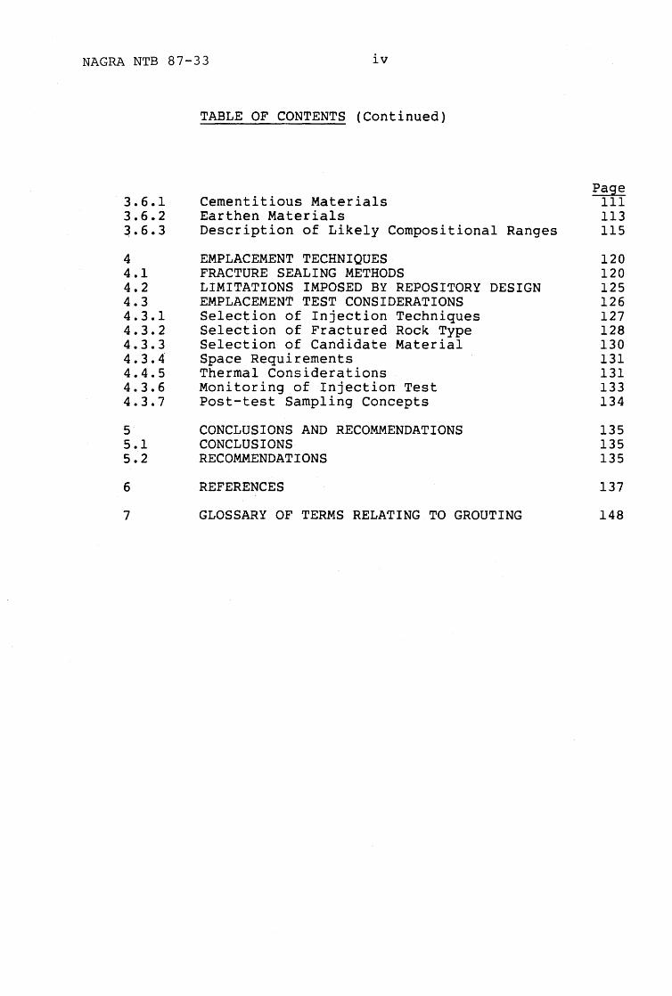
TABLE OF CONTENTS (Continued)
Cementitious Materials Earthen Materials Description of Likely Compositional Ranges
EMPLACEMENT TECHNIQUES FRACTURE SEALING METHODS LIMITATIONS IMPOSED BY REPOSITORY DESIGN EMPLACEMENT TEST CONSIDERATIONS Selection of Injection Techniques Selection of Fractured Rock Type Selection of Candidate Material Space Requirements Thermal Considerations Monitoring of Injection Test Post-test Sampling Concepts
CONCLUSIONS AND RECOMMENDATIONS CONCLUSIONS RECOMMENDATIONS
REFERENCES
GLOSSARY OF TERMS RELATING TO GROUTING
Page III 113 115
120 120 125 126 127 128 130 131 131 133 134
135 135 135
137
148

NAGRA NTB 87-33
TABLE NO.
2-1
2-2
2-3
3-1
3-2
3-3
3-4
3-5
v
LIST OF TABLES
TITLE
Criteria for comparative evaluation of seal materials
Summary of additives for cementitious materials mixes
Summary of chemical grouts
Physical properties of grout (approximately 130 days water curing at 7°C)
Summary of permeability and erodability studies on bentonite-bearing grouts (Chan, 1986)
Summary of general issues for priority seal materials for fracture sealing
Shear strength and plastic viscosity of neat cement grouts
Compositional ranges of priority sealing materials

NAGRA NTB 87-33
FIGURE NO.
2-1
2-2
2-3
2-4
3-1
3-2
3-3
3-4
3-5
vi
LIST OF FIGURES
TITLE
Screen of preliminary candidate seal materials
Crystal structure of smectite
Calculated and measured effects of density on the maximum swelling pressure of a compacted Wyoming (Na-rich) bentonite
Hydraulic conductivity of compacted bentonite/ sand mixtures as a function of bentonite content
The solubility of silica and alumina as a function of pH (after Correns, 1949)
Differential thermal analysis (DTA) curve for a smectite (nontronite) with quartz added as an internal standard. The magnitude and locations of peaks are characteristics of exothermic or endothermic reactions occurring at elevated temperatures
Illite/smectite expandabilities in natural mix-layer clays versus the temperature of the formation in which they occur.
Illite/smectite expandabilities for selected Gulf Coast shales as related to age.
Extent of reaction for a beidellite composition glass reacting to illite as a function of time (slope of each isotherm provides a rate constant for the illitization reaction), at 200 MPa (29,000 psi).

NAGRA NTB 87-33
Figure No.
3-6
3-7
4-2
4-3
4-1
vii
LIST OF FIGURES (Continued)
TITLE
Relationship between temperature and the time for the illitization reaction of a beidellite composition glass calculated from experimentally determined rate constants (Figure 3-5), at 200 MPa (29,000 psi)
Stability relationship diagrams for several common lowtemperature clay minerals calculated for the activity ~f several cations (K+, Na+, Mg +, H+) against silica activity, at 25°C, 1 atmosphere
Major fractures in heater hole no. 1 of the Buffer Mass Test at Stripa
Prototype for sealing of BMT heater holes. The grout is injected through the 1" tube, fills the space between the rubber sealings (R) and enters fractures which are exposed in the rock (F)
Principle for injecting rock with "dynamic injection technique".
A) percussion drilling machine, B) steel cylinder, C) slurry container, E) transducer F) valves, G) air pressure, I) borehole, 2) packer, 3) highpressure hose, 4) valve

NAGRA NTB 87-33 viii
EXECUTIVE SUMMARY
This state-of-the-art report has been prepared by
the members of the technical OECD/NEA-sponsored
Stripa Task Force on Sealing in furtherance of
Phase III of the Stripa Project. The objectives
of the report are: 1) to review progress in the
development of seal materials and emplacement
techniques; 2) to identify priority issues and
materials for sealing narrow aperture fractures;
and by so doing, 3) to provide a basis for devel
oping seal test programs such as that intended for
implementation at the Stripa Facility.
A system of seals may be a desirable or necessary
element to assure that repositories prevent release
of unacceptable amounts of radioactive waste.
Although such seals may be included in repository
systems, quantitative performance objectives
cannot be specified generically; rather, perform
ance specifications await definition on a case-by
case basis. Generalized performance objectives
can be defined, however. These objectives include
restricting water flow through the repository,
working compatibility with the in situ environment
and other repository barrier components, and
maintaining performance over an unspecified but
long duration of time (many thousands to perhaps
millions of years). During analysis and
recommendation of materials, practical constraints
such as the ability to emplace seals, a history of
successful use of the material, the availability
and cost of materials, and the desire to use
comparatively safe (i.e., non-toxic) materials
were also considered.

NAGRA NTB 87-33 ix
The initial list of material classes analyzed
included cementitious materials, ceramics, chemical grouts, clay materials, cement/clay
materials, metals, and organic substances (bitumen, tars, etc.). Of these, cementitious
materials and clay materials are recommended as priority materials because they can be designed to
meet all of the desired performance characteristics, there is a considerable history of success
ful use in similar engineering applications, and there is indirect evidence that they will continue
to perform for long periods of time. Chemical grouts are identified as a promising class of
materials that could be very useful for specialty applications. Chemical grouts were not selected
as a priority material because of their cost and because evidence for long-term performance is
lacking_ Cement/clay and bituminous materials may possess important performance characteristics but
have uncertain long-term performance. Both chemical grouts and bitumen have uncertain effects
on radionuclide mobility because of the introduction of organic substances into the repository
system. Synthetic materials, ceramics, and metals, are deferred in this report either for
practical reasons (e.g., emplaceability) or because the ability to provide seal functions
appears unlikely. Figure ES-l illustrates an example of the material screening process and
results. The significance of the figure is the process of materials screening, a technique
applicable to all programs. The ranking of criteria and materials shown in the figure may
vary from site to site and do not necessarily represent a consensus of all contributors to this
report.

Figure ES-l. Screen of preliminary candidate seal materials*
--
I Extensive
Ability to History of Systematic Criteria Perform as Effect on Usage in Data Base on
Hydrologic Emplace- Long-Term Mobility Materials Engineering Chemistry and Low I
Material Barrier ability Stability Radionuclide Availability Practice Performance Cost, Sign1f1cance of ~riteria
. -- ---_ .. _- V~ImpoI1?nt ,-- Important Desirable
Cementitious Materials
Clays (Bentonite)
: : : : : : : YpriOrityl
Cement-Clay Mixtures
Chemical Grouts
Bitumen
: : : : : : : : !110W pr i ori t y I
Ceramics
Metals
Synthetic FractureFilling Minerals
• acceptable performance
• performance uncertain
• •
• •
• • •
• • •
from further consideration for near-term studies
• acceptable performance probably achievable
o probably unacceptable performance t
• • •
*Mixtures and combinations may be used. +unacceptable performance will disqualify materials from priority consideration for grouting.
• o
• • • •
z ~ G')
~ Z 1-3 IJj
co -.....]
I w w
><

NAGRA NTB 87-33 xi
With clay materials and cementitious materials
identified as priority candidate materials, each material class is discussed in terms of behavior.
Cementitious materials achieve low permeability by being formulated to have minimum porosity and by
avoiding shrinkage and fracturing. Hydraulic conductivities in the range of 10-8 to 10-10
cm/sec are achievable if water:cement ratios are in the range of 0.3 to 0.5. The materials will
probably require the use of pozzolanic additives and plasticizers. Conductivities in this range
can probably be maintained if cementitious materials are not exposed to temperatures above
100°C. Clay materials achieve low permeability by a combination of physical and chemical processes.
Clays absorb water into their structures and develop internal swelling pressures that resist
water flow (both internally and at interfaces). Conductivities less than 10-10 cm/sec can be
achieved with Na-bentonite so long as a reasonable dry density is engineered on emplacement.
Emplacement considerations (i.e., mix design
requirements to achieve a pumpable, high
penetration grout) may affect the properties of
the material.
Clay materials deform plastically and reversibly
at temperatures below about 300 0 Ci hence, they may
be preferred for high temperature applications.
Note, however, that depending on water chemistry, elevated temperatures may enhance the kinetic
rates of alteration to less favorable clays (e.g.,
illite). Clay grouts also tend to be eroded under
high hydraulic gradients and groundwater flow
rates. Detailed discussion along these lines
results in identification of a preliminary set of

NAGRA NTB 87-33 xii
issues that can be resolved through field or
laboratory tests so that confidence in acceptable performance of designs is ultimately increased.
These issues are shown on Table ES-I. It should be emphasized, however, that this list is
preliminary and may be augmented or deminished as Stages III and IV of Stripa Phase III progress or
as member countries advance seal system designs.
Familiar technologies for emplacing seals in fractures include pressure injection, dynamic (or
vibratory) injection, and electrophoresis. Electrophoresis, the process of inducing clay
migration into fractures by imposing an electrostatic potential along the fracture, is least
promising because of the need to drill additional holes for electrodes and uneven results in field
tials. Normal pressure injection will probably prove satisfactory for many fracture sealing
needs. Attempts to seal narrower fractures using this standard technique are likely to result in
damage to the host rock. There are, however, two
dynamic injection techniques. One utilizes
mechanical vibration (Pusch, et al., 1985) and the other employs ultrasonic wave energy (Kameda,
1983). These vibratory techniques are superimposed on standard pressure injection techniques
and enhance penetration by decreasing the internal
friction between particles in the grout slurry.
Both techniques can be applied to either cementitious or clay grouts, with penetrations on
the order of decimeters reported in fractures with apertures on the order of 0.1 rnrn.

NAGRA NTB 87-33 xiii
Table ES-l. Summary of general issues for priority grouting materials for fracture sealing
Issue
(1) Define materials performance requirements.
(2) Select starting materials and prepare mix design(s); characterize selected materials.
(3) Select key materials properties and determine materials performance with respect to performance with respect to performance requirements; optimize materials properties.
Proposed Approach
Perform modeling of seal performance under several release scenarios including site geology, site hydrology, site geochemistry, repository design and (in situ conditions) site performance regulatory criteria (if any) to determine seal performance requirements for hydraulic conductivity, retardation potential, performance longevity, mechanical properties. Performance requirements are site specific based on (1), select cementitious materials and additives likely to produce desirable characteristics using test data and industry literature; priority should be given to inexpensive, available materials.
Determine limited range in which design parameters may be varied from literature. Perform trial mixes and preliminary laboratory tests (e.g., viscosity, penetrability, bleed, strength, hydraulic conductivity); select mix(es) based on (1) for further study.
Select key properties of grout based on (1) and devise test program. Perform standard laboratory tests to evaluate properties of selected materials.
Materials properties may include:
Viscosity
Bleed
Penetrability/set time
Hydraulic conductivity

NAGRANTB 87-33 xiv
Table ES-l. Summary of general issues for priority grouting materials for fracture sealing (continued)
Issue
(3) (Continued)
(4) Establish longevity requirements for grout and determine materials performance longevity (stability).
(5) Determine effects of grout material, emplacement, or alteration products on radionuclide mobility.
Proposed Approach
Interface hydraulic
conductivity
Unconfined/confined compressive
strength
Thermal expansion
Tensional strength
(flexural)
Shear strength/erodability
Based on (1), establish the longevity requirements for grout performance; longevity requirements will be sitespecific and probably specific to individual seals, materials, seal functions, or locations within the facility; estimate long-term compatibility to performance of grout in host environment through real-time and accelerated laboratory testing of grout materials; perform geochemical modeling, thermodynamic and kinetic calculations to estimate types and rates of materials alteration and consequences on performancej host environment includes host rock, ground water, waste, adjacent seals, backfills, waste package, temperature and pressure conditions.
Perform laboratory solubility and sorption testing using selected grout materials, alteration products (4), and altered ground water compositions and key radionuclides or analogs.
NAGRA NTB 87-33 xv
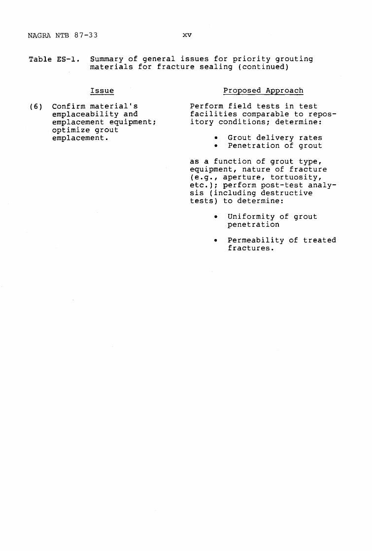
Table ES-l. Summary of general issues for priority grouting materials for fracture sealing (continued)
Issue
(6) Confirm material's emplaceability and emplacement equipment; optimize grout emplacement.
Proposed Approach
~erform field tests in test facilities comparable to repository conditions; determine:
• Grout delivery rates • Penetration of grout
as a function of grout type, equipment, nature of fracture (e.g., aperture, tortuosity, etc.); perform post-test analysis (including destructive tests) to determine:
• Uniformity of grout penetration
• Permeability of treated fractures.

1 INTRODUCTION
This State-of-the-Art Report on sealing small
aperture fractures in mined nuclear waste repositories is a compilation and summary of information
provided by international participants in the
Stripa Project. Contributors to this document are:
• Atomic Energy of Canada, Ltd.
• Building Research Establishment (UK)
• Nationale Genossenschaft fur die Lagerung Radioaktiver Abfalle (NAGRA) (Switzerland)
• Office of Crystalline Rock Development, Battelle Memorial Institute (USA)
• Swedish Geological Co.
• Swedish Nuclear Fuel and Waste Management Co. (SKB)
• Technical Research Centre of Finland
• University of Tokyo (Japan).
The information presented and the conclusions drawn
in this report are the result of discussions and acceptance among the participants representing
these institutions. The conclusions, however, do not represent consensus among the contributors for
the materials, issues, or research requirements applicable to their individual programs.
1.1 HISTORY OF THE STRIPA PROJECT
SKB:l35-Secl
The Stripa Project is an international cooperative
effort in the study of nuclear waste management. The Stripa Mine in central Sweden is an iron ore
SKB:135-Secl
2
mine in granitic host rock that has been actively
exploited since the Middle Ages. In 1977-1980, after it was abandoned for iron mining, the Stripa
Mine was the site of a series of investigations related to nuclear waste storage. Tests were
performed in facilities excavated in the mine as part of a cooperative agreement between the Swedish
Nuclear Fuel and Waste Management Co. (SKB) and the
United states Department of Energy (DOE).
The investigations included in situ tests to
examine the thermomechanical and hydrological properties of fractured, saturated granite as part of
an effort to improve understanding of conditions expected in the disposal of nuclear wastes in
crystalline rock bodies. The particular tests included a time-scaled heater test to investigate
the long-term thermomechanical response of granite to thermal loading; a full-~cale heater test that
simulated the short-term, near-field effects of the thermal pulse from emplaced nuclear wastes; and
hydrological tests that included large-scale
measurements of the hydraulic conductivity of the
fractured rock mass. This series of tests provided the foundation of knowledge upon which the Organi
zation for Economic Cooperation and Development/ Nuclear Energy Agency (OECD/NEA) Stripa Project was
based.
In 1980, a cooperative effort for research at the Stripa Mine was organized in the form of the
autonomous OECD/NEA Stripa Project. Under the management structure for the Stripa Project, the
responsibility for supervision for the research
program and for its finance resides with the Joint
Technical Committee (JTC) which is composed of

SKB:135-Secl
3
representatives from each of the participating
countries. The JTC also provides information on
the general progress of work to the DECO Steering
Committee for Nuclear Energy, through the NEA committee on Radioactive Waste Management and its
Coordinating Group on Geological Disposal. Each
research investigation is assigned to a principal
investigator. The conception of the experiments
and their realization are periodically reviewed by
two Technical Subgroups that deal with (a) hydrogeology, chemical transport, and geophysics and (b)
engineered barriers and rock mechanics. These
Technical Subgroups are composed of scientists and
engineers from the participating countries. The
SKB acts as the host organization and provides the
day-to-day management for the project.
The Stripa Project has been organized into
Phases. Phase I and Phase II are complete, and
Phase III is currently being performed. During Phase I, which lasted from 1980 until 1984, the
participating countries were Canada, Finland, France, Japan, Sweden, Switzerland, and the United
States. The first phase of the Stripa Project
consisted essentially of three principal
investigations:
• Hydrogeological and geochemical investigations of the granite rock mass to a depth of 1,230 meters below the ground surface
• Tracer migration tests to study mechanisms of radionuclide transport in the rock fractures
• Large-scale tests of the behavior of bentonite backfill material in waste emplacement boreholes and tunnels under conditions of elevated temperature.
SKB:135-Secl
4
Phase II of the Stripa Project began in 1983 and
was completed in early 1987. The original seven countries continued to participate in the Project
and were joined by Spain and the United Kingdom. The investigations that were performed in the
Stripa Mine in this second phase were:
• The development of crosshole geophysical and hydraulic methods for the detection and characterization of fracture zones
• Extended tracer migration experiments to study further the mechanisms of radionuclide transport in fractured granite
• The sealing of boreholes, tunnels, and shafts by use of highly compacted bentonite.
In 1985, the elements of a third phase of
investigations for the Stripa Project were first
conceptualized and then incorporated into a Program Plan for review by technical experts of the parti
cipating countries. After completion of the review of the Program Plan and accompanying modifications
during the early part of 1986, Phase III of the
Stripa Project was initiated in late 1986. The
participating countries include Canada, Finland, Japan, Sweden, Switzerland, the United Kingdom, and
the United States. Under Phase III, which is scheduled for completion in 1991, there are three
principal investigations:
• Characterization and validation of geologic structure, groundwater flow, and nuclide transport in a large, previously unexplored mass of Stripa granite
• Continued development of site characterization methods and concepts, including those related to borehole radar, borehole seismics, fracture-flow network modeling, in situ fracture characteristics, and tracer migration in fractured rock

5
• Identification, selection, and evaluation of materials (e.g., bentonite, cementitious or other grout) for the long-term sealing of fractured rock, including an in situ demonstration of the effectiveness of such materials for the long-term sealing of fractures that may act as groundwater flow paths.
Because of the integrated nature of these investi
gations, the two Technical Subgroups (hydrology/
transport/geophysics and engineered barriers/rock
mechanics) have been combined into a single group
for Phase III.
Rock sealing activities, as part of Phase III, are
subdivided into five stages:
• Stage I - State-of-the-art survey of fracture sealing materials
• Stage II - Determination of the physical properties of the grouts in the injection phase and in the injected state
• Stage III - Determination of the long-term stability
• Stage IV - Field pilot tests
• Stage V - Planning of large scale sealing test in deposition holes.
This report represents a first stage in the
investigation of the sealing of fractured rock.
1.2 SCOPE OF THE REPORT
SKB:135-Secl
This state-of-the-art report on sealing small
aperture fractures in nuclear waste repositories is
intended to aid selection and characterization of
materials that are most promising for long-term sealing of groundwater flow paths in fractured

6
crystalline rock. The results of this survey will
contribute materials and materials handling input to Stage Iof the Phase III investigations at
Stripa that address sealing of fractures, particularly fractures such as those that intersect waste
emplacement boreholes.
Topics to be covered in this report are the identification and discussion of:
(1) Priority candidate materials for sealing fractures in crystalline rock (based on performance properties, chemical or physical stability);
(2) Lower priority seal materials;
(3) Handling and emplacement techniques that produce significant reduction in the mass permeability of the fractured rock; and
(4) Recommendations for continued sealing materials and emplacement research.
This document is derived from the review and
interpretation of current literature and does not represent a report of original research or testing
results. It covers literature related to repository sealing, with emphasis on discussions that
pertain to sealing small aperture fractures. This report is not intended to summarize the entire
repository sealing literature or to incorporate generic engineering literature that may be only
peripherally relevant.
1.3 FORMAT OF THE REPORT
SKB:135-Secl
Following this Introduction (Section 1), Section 2 describes the performance objectives of seals,
emphasizing seals placed in fractures, shows an example of a screen of the materials that have been

SKB:135-Secl
7
considered candidate fracture sealing materials,
and identifies the priority materials for sealing fractures in granitic rock. Section 3 presents an
overview of the sealing properties of the priority candidate sealing materials. Formulations of these
materials that appear to meet sealing objectives are also presented in Section 3. Section 4
summarizes the techniques that have been investigated to emplace seals in fractures. Section 5
states the conclusions of this report and recommendations for materials development, emplacement
techniques, and further research. References and a glossary of terms are included in the final two
sections (Sections 6 and 7).

8
2 PERFORMANCE OBJECTIVES OF SEALING MATERIALS AND SELECTION OF PRIORITY MATERIALS
2.1 RECOMMENDED PERFORMANCE PROPERTIES
SKB:l35-Sec2
Repository seals may be used in nuclear waste
repositories to limit groundwater flow into and
away from the facility. Radionuclide transport is
expected to occur chiefly by means of dissolved,
colloidal, or suspended material in groundwater.
Therefore, limiting the movement of groundwater
through the repository by the use of seals may
contribute to meeting performance objectives of the
facility.
If seals are either necessary or desirable to meet
repository performance, at least two sealing
strategies may be employed; moreover, the strate
gies may be employed either separately or in combination. The first strategy is to limit flow
through the mined accesses (drifts, shafts, etc.) to the waste emplacement rooms. This strategy
emphasizes intercepting main flow channels and
diverting flow into the county-rock (i.e.,
restoring the host rock to a semblance of its
preconstruction condition). Seal system designs
for plugging man-made openings may include seals
for fractures that would otherwise short-circuit
seals placed in shafts and drifts. Such fractures include natural joints and faults, random frac
tures, and fractures related to construction
activities, such as the damaged rock zone
surrounding the openings.

SKB:135-Sec2
9
The second sealing strategy is to limit the access
of water to the waste by focusing on the pathways
that groundwater must traverse to reach the waste.
Although groundwater flowpaths in fractured rock are difficult to predict, it can be stated with
certainty that if groundwater is to transport radionuclides away from the repository, it must
pass through the fractures that emanate from the
waste disposal holes drilled into the floor or ribs
of the mined facility. If those fractures are
sealed effectively no waste can be accessed by
water; hence, no waste can be dissolved or
transported from the repository. Moreover, Pusch
et ale (1985) have suggested that if fractures
intersecting waste emplacement holes were sealed
such that groundwater flow were virtually nil
within several meters of the emplaced waste, then
the stability of the waste canister and overpack would be improved, and the diffusional migration of
radionuclides through the canister overpack
following canister breach would be ensured.
As implied above, it is not clearly established
that a system of repository seals is necessary to
achieve acceptable performance by repositories.
However, in those cases where seals are desirable
or necessary, the general performance characteris
tics for seals, including fracture seals, in a
nuclear waste repository include:
• Low hydraulic conductivity, including the seal itself and the interfaces between the seal and the host rock to minimize groundwater flow in sealed zones
• Physical properties that will permit the seal to maintain low hydraulic conductivity under in situ thermal and mechanical stresses

10
• Chemical compatibility with the host rock, groundwater, and the physico-chemical environment in the seal zone to limit any alteration of the seal that would increase its hydraulic conductivity
• With respect specifically to fracture sealing, desirable physical and chemical properties of the sealing material will include those that significantly reduce the erodability of the material from fractures under significant hydraulic heads (up to several MPa).
Longevity of performance is an issue that must be
addressed during candidate material selection.
Longevity is discussed further in Section 2.2. All
contributors generally agree that seals, if used,
should perform for a long period of time; however,
the exact length of time that seals should operate
is not well-defined. For the purposes of this
document, "a long time" is qualitatively considered to be on the order of thousands to millions of
years following the operational period of the repository. Physical and chemical compatibility
between the seal materials and the host environment are required to assure long-term performance of the
seals.
2.2 LONGEVITY EXPERIENCE WITH LOW PERMEABILITY SEAL P-ATERIALS
SKB:135-Sec2
As noted above, neither the need for seals nor the
longevity requirements for seal functions have been
uniformly agreed upon by participating countries.
Nevertheless, seal longevity is an issue that
members have agreed should be addressed. The most
commonly accepted approach to determining long-term
seal performance is to establish the long-term

SKB:135-Sec2
11
physical and chemical stability of the seal
material itself. By inference, the seal functions
will be achieved so long as the material remains
intact or any alteration can be shown to have no
effect on critical seal performance properties,
such as low hydraulic conductivity. In this
regard, several quantitative research programs have
been established in member countries to evaluate
the longevity of selected candidate seal
materials. These include laboratory studies and
natural analog studies. The results of these
quantitative studies are summarized in Section
3.3. In this section, however, a general overview
of experience with the longevity of common sealing
and grouting materials is presented.
Inference regarding materials longevity may be
derived from several disciplines. These include:
• History of engineering applications • Archeology • Geology.
Inferences derived from these disciplines are, for
the most part, qualitative and can only be coarse
indicators of longevity of candidate seal
materials. Materials that have considerable
history of engineering applications and may have
importance in repository sealing are cements,
clays, ceramics, metals, bitumen and tars, chemical
grouts, quartz sand, and almost all common rock
types and minerals (crushed and intact).
Inferences drawn from engineering applications -
Engineered structures to retain or seal out mois
ture, have been fabricated for several millennia
primarily from cementitiolls, rock, and bituminous

SKB:135-Sec2
12
materials. However, applications such as aqua
ducts, cisterns, etc. are generally poor analogs for saturated, subterranean environments. More
modern structures such as cementitious and earthen material dams, shaft liners, borehole plugs, and
rock seals, have shown that sealing materials can be engineered to remain intact and perform
satisfactorily under in situ conditions for periods on the order of decades or, more rarely, a century
or more. Thus, indirect evidence for longevity oE performance is promising but inconclusive. If
repository seals must perform for many thousands or millions of years, then the practical experience
with sealing and grouting materials is too incomplete to provide a reliable measure of seal
material longevity for repository sealing purposes.
Inferences from archeology - Several types of manmade materials that may act in low permeability
seals are found in ancient artifacts and structures which suggest the materials are stable under some
conditions for thousands of years. These materials include ceramics (among the oldest man-made mater
ials), cementitious materials (a type of ceramic), and metals. Much like engineered structures,
inferences based on archeological evidence are limited because the conditions to which the
materials have been exposed are probably unlike repository conditions. In addition, raw materials
and ancient production practices are largely unknown, and several millennia represents less time
than the expected longevity requirements of repository seals.
Inferences from geology - Inferences concerning
potential seal longevity for periods that exceed

13
human experience requires reference to geologic
time and geologic materials. Although frequently
uncertain, the age of most geologic materials is as
great or exceeds the many thousands to millions of years that seal materials may be required to
function. In addition, geologic environments are occasionally not unlike repository conditions.
Examples of such environments may be found in dia
genetic and metamorphic terrains, and geothermal
environments. Key geologic materials that may be
significant for sealing applications are clays,
naturally-occurring fracture-filling minerals, bitumen, as well as rock, sand, and gravel. The
very persistence of repository host rocks infers
that, if crushed to a sufficiently fine size or if
used in combination with other low permeability
materials, utilization of crushed host rock in seal
components may be a simple approach to obtaining
long-lived seals.
2.3 OTHER CONSIDERATIONS AFFECTING SELECTION OF LOW PERMEABILITY SEAL MATERIALS
SKB:135-Sec2
Several additional factors, not directly related to
materials performance as a long-lived hydrologic
barrier, will strongly affect the performance of
seals and seal materials and the selection of seal
materials for a nuclear waste repository. For
example, key to the selection of any seal material
must be evidence that the material can be emplaced
effectively using existing technologies or practi
cal new emplacement methods. With specific
reference to fracture sealing, the seal material
should be injectable into rock fractures with
little or no additional damage to the rock and with penetration on the order of several decimeters.

SKB:135-Sec2
14
Note that materials and emplacement technologies
will be required to seal fractures on the order of 0.1 mm aperture and smaller (Pusch et al., 1985;
Pusch, 1986). This requirement places additional constraints on seal material and emplacement
technology selection as discussed further in Sections 3 and 4.
An additional consideration for selecting seal
materials is to evaluate whether the waste isolation capacity of the repository and other
engineered barriers will be enhanced or compromised by the seals or by their alteration products and
by-products. For example, the degradation of seal materials should not significantly enhance the
chemical mobility of radionuclides. Accordingly, the potential effects of by-products of seal
material alteration, interactions between seals and the host environment, or irradiation of seal
materials on radionuclide mobility must be considered in materials selection.
Some candidate seal materials (e.g., clays) may
enhance the isolation ability of a repository by retarding the migration of cationic species by
sorption or reaction (i.e., adsorption, cation exchange, precipitation). Other materials,
however, may enhance radionuclide mobility by introducing chemical complexing agents (e.g.,
carbonate, sulfate) or organic materials capable of chelating radionuclides. These materials must be
excluded from priority consideration for sealing. This consideration is further described in Section
2.3.

SKB:135-Sec2
15
Priority materials recommended in this report for
sealing of fractures are familiar in engineering applications, with strong evidence that the
materials have been successfully emplaced and performed adequately for the functional lifetime of
the engineered structure. Familiar materials with well-known engineering properties will help reduce
research and development costs for both materials and emplacement technology. The preferred
materials should be reasonably safe to handle and should not contain excessive amounts of hazardous
substances that may present additional environmental, logistical, or licensing issues. This
rationale also extends to early demonstrations of materials for sealing (such as Stages III and IV of
Phase III tests); hence, the use of established materials for sealing purposes is a constraint
adopted in this document. Logistics and limitations on the emplacement of seal materials must be
considered in selection of seal materials and a sealing strategy. Limitations may arise due to the
space requirements for machinery, energy input requirements to obtain adequate sealing, and
safety/precautionary measures required during seal emplacement.
Priority sealing materials must be available in
large quantities. Variability in materials composition and performance between batches of starting
materials (e.g., cement, bentonite, additives, aggregate, water, etc.) should be minimal. Cost
will be a secondary consideration relative to performance. Thus, additional considerations for
selecting priority candidate seal materials include:

16
• Emplaceability, with adequate seal performance and assurance that a high quality seal will be produced
• Chemical effects on radionuclide mobility
• Experience in using and handling the material during engineering projects, particularly mining, tunneling, or other groundwater control projects
• Emplacement logistics and limitations related to emplacement of the materials in a confined underground space (space limitations, power consumption, toxicity, safety, etc.)
• Material availability and uniforimty
• Materials cost.
2.4 SUMMARY OF CRITERIA FOR COMPARATIVE EVALUATION OF SEAL MATERIALS
SKB:135-Sec2
Criteria for materials selection for repository
seals based on seal performance properties and additional considerations for sealing are
summarized in Table 2-1. The criteria fall into two categories: those necessary for acceptable
seal performance and those that are desirable but not necessary to achieve adequate performance.
Materials that possess the necessary characteristics but do not possess the other, desirable
characteristics, may nevertheless be successfully
applied in repository sealing. These latter
characteristics may discriminate between materials
possessing otherwise equivalent properties. In
general, development of a seal material meeting
these desirable criteria would consume fewer
resources (research, laboratory and field testing,
etc.) than materials that do not meet these
criteria.

17
Table 2-1. Criteria for comparative evaluation of seal materials
NECESSARY CHARACTERISTICS
1. Ability to perform as hydrologic barrier
Low intrinsic permeability
Low interface permeability (interface between seal and host materials)
2. Emplaceable in repository environment
Emplaceable using existing or practical new technology
Penetrate fractures uniformly, with good void filling to several decimeters depth or more with little or no damage to host rock
At least some material will meet the above criteria for fracture apertures as small as 0.1 mm
Minimum environmental hazard inherent in utilization
3. Ability to perform #1 over the long-term
Chemical stability under in situ physico-chemical conditions, or alteration does not impact ability to achieve criteria in #1 (above).
Physical stability under in situ stresses (mechanical, thermal, hydrologic)
4. Cause no enhancement of radionuclide mobility
Seal material, alteration products, and byproducts do not increase radionuclide solubility, do not reduce radionuc1ide sorption by host rock or other seal components, etc.
5. Available in large volumes with uniformity between batches
SKB:135-Sec2

18
Table 2-1. Criteria for comparative evaluation of seal materials (Continued)
DESIRABLE CHARACTERISTICS
1. Long history of use and well-documented performance in
engineering projects similar to nuclear waste repositories
(dams, tunnels, mines, foundations)
2. Extensive and systematic data bases on:
Material chemistry
Performance as function of chemistry, preparation procedures, environmental conditions
Emplacement technology
3. Low cost
Low materials cost
Minimal research and development cost
Low emplacement equipment cost (including research and development)
SKB:135-Sec2

19
The criteria presented in Table 2-1 are
qualitative. This situation necessarily arises because no quantitative criteria will universally
apply to all repository programs. The specific requirements for seals, if any, will undoubtedly be
site specific and may vary widely from site to site. For purposes of this report, however, these
general and widely applicable criteria are presented.
2.5 DESCRIPTION AND SCREEN OF PRELIMINARY CANDIDATE SEAL MATERIALS
SKB:135-Sec2
Several studies have included comparisons among
materials groups with respect to the potential for use in seals for nuclear waste repositories (e.g.,
Taylor et al., 1980; ONWI, 1980; Pusch et al.,
1985; Gray, 1986). These reports have identified
several groups of materials and several specific materials that may be considered for sealing.
Among the candidate materials types that may be used in fracture sealing (specifically) are:
• Cementitious materials • Earthen materials, particularly clays • Cement/clay materials • Chemical grouts • Bitumen • Fracture filling minerals • Ceramics • Metals.
The following sections define these materials and
describe a preliminary screen of the materials with respect to the criteria on Table 2-1. The screen
is illustrated in Figure 2-1. The screening mechanism is widely applicable to the members'
repository programs and represents an agreement among the participants on the overall screening

(J1
~ to ....., w U1 I
(J1
CD () tv
Criteria
Material SignIfIcance of Criteria
Cementitious Materials
Clays (Bentonite)
Cement-Clay Mixtures
Figure 2-1. Screen of preliminary candidate seal materials*
Extensive I Ability to History of Systematic
Perform as Effect on Usage in Data Base on Hydrologic Emplace- Long-Term Mobility Materials Engineering Chemistry and Low Barrier ability Stability Radionuclide Availability Practice Performance Cost
Very Important Important Desirable
- - - - ---- .. - - -•
- - ~--.~ pr ior it y I . . . . . .-- .
Chemical Grouts
Bitumen
• • • •
: : : e· : j : I J uw p r i "r i t y I
Ceramics
Metals
Synthetic FractureFilling Minerals
• acceptable performance
• performance uncertain
• • • • • •
• • • • from further consideration for near-term studies
• acceptable performance probably achievable
o probably unacceptable performance t
• • •
AMixtures and combinations may be used. tUndcceptdble performance will disqualify materials from priority consideration for grouting.
• o
• • • •
tv o

21
approach. The ranking of selection criteria and
the outcome of the screening may vary from program to program, however, and should not be interpreted
as a consensus of the participants.
2.5.1 Cementitious Materials
2.5.1.1 Definition and Overview of Cementitious Materials
SKB:135-Sec2
For purposes of this report, cementitious materials include portland cement-based grouts, mortars, and
concretes. Portland cement is a complex material composed of six major compounds (Aitcin, 1986):
• Tricalcium silicate • Dicalcium silicate • Tricalcium aluminate • Tetracalcium ferroaluminate • Gypsum • Alkali sulfate.
The cement is manufactured by heating siliceous
limestone and combining the resulting clinker with gypsum during grinding. The cementitious property
of these materials is obtained by the formation of
a hydrous calcium-silicate gel resulting from the
mixing of and exothermic reaction between water and cement. Neat cement paste (the plastic material
obtained by mixing water with powdered cement) contains no aggregate. Mortar contains fine
aggregate (sand), and concrete contains both fine and coarse aggregate. Cementitious grout is any
cementitious mixture that can be injected into a
formation without regard for the amount or size of
aggregate that may be included.
The properties of both the cementitious slurry and the cured grout can be varied, and certain

SKB:135-Sec2
22
desirable properties can be enhanced, through mix
design. Common mix design variables include cement type, water:cement ratio (w/c), the type of aggre
gate, if any, and the types of additives included: pozzolans, accelerators, expansive agents,
plasticizers, etc.
Portland cements commonly used in engineering applications and applicable to repository sealing
include Ordinary Portland Cement (ASTM Type I, API Class A, CSA Type 10), Sulfate Resistant Cement
(ASTM Type V, CSA Type 50, as well as most API cement classes in sulfate resistant form) and High
Early Strength Cement (ASTM Type III, API Class C, CSA Type 30) (e.g., Roy et al., 1985; Gray, 1986).
Some repository sealing studies have emphasized API Class H cement, a basic well cement available as
moderate and high sulfate resistant types (e.g., Roy et al., 1983, 1985). Expansive (tlshrinkage
compensating") cements (e.g. Class K, ChemComp) have also received some attention in sealing
studies (Gulick, 1978; Ballivy, 1986), and ordinary
cements can be formulated to be expansive with
appropriate additives in the mix.
Several types of additives are regularly used in the preparation of cementitious materials. Addi
tives are materials added to the mix after manufac
turing the cement, except water. The significance
of these materials is summarized in Table 2-2. A key additive to improve stability and long-term
performance of portland cement-based materials is pozzolan. Pozzolan is a group of reactive
siliceous materials (e.g., fly ash, silica fume,
etc.) that combine with free Ca(OH)2 in the
hydrated cement paste during the curing of the

(/)
~ tJj
I--' LV U1 I
(/) ro n tv
Type of Additive
1. Pozzolans
2. Plasticizers (fluidifiers, water-reducers, high-level waterreducers, superplasticizers)
3. Mineral additives
4. Accelerators
5. Retarders
Table 2-2. Summary of additives for cementitious materials mixes
Examples of TypicallyUsed Additives
Silica fume Silica flour Fly ash (several sources) Blast furnace slag
Melamine formaldehyde Sulfonated napthalene formaldehyde
Lignosulfonic acid and their salts Hydroxylated carboxylic acid and their salts
Clay, quartz powder, ground limestone, bentonite
CaC1 2 Other chlorides, carbonates silicates, and organic compounds (e.g., triethanolamine)
Lignosulfonic acid salts hydroxylated carbonic acid salts
Comments on Usage of Additives
Promote "pozzolanic" reaction between products of cement hydration (e.g., CaOH) and reactive silic~ (pozzolan) to produce cementitious C-S-H, reduce porosity, and improve strength
Lower water requirement for a given slump or degree of workability; improves workability and lowers viscosity of low water:cement ratio mixes; may tend to retard set of material
Improve workability and reduce bleed; improve suspension of aggregate and particulates; increase stiffness and density of paste
Achieve early setting time. CaC1 2 is used up to 2 wt% of cement. May be detrimental to cementitious materials at high temperature, reduce sulphate resistance, and increase shrinkage
Generally the same materials as water reducers; set time can be extended 30-50%; often used to offset accelerating effects of high temperature emplacement environment
N LV

(f)
~ tJ:I
I-' W Ln I
(f)
CD o tv
Table 2-2. Summary of additives for cementitious materials mixes (Continued)
Type of Additive
6. Expansionproducing additives
Examples of TypicallyUsed Additives
a) Aluminum, magnesium powders
b) Calcium sulfo-aluminate
Comments on Usage of Additives
a) Gas (H 2 , 02' N2 ) producing, cause expansion in plastic state
b) Produce expansive phase ett:ringite in hardelled state "/
c) Iron/iron-based compounds, c) Produce high volume o5C:idation products in hardened state
7. Air-entraining additives
8. Defoamers
9. Permeability reducers
10. Corrosion inhibitors
magnesium
Salts of wood resins, synthetic detergents, salts of sulfonated lignin, salts of petroleum acids, salts of proteinaceous materials, fatty and 'resinous acids and their salts
Tributyl phosphate
Soaps, oils, resins
Sodium benzonate, calcium lignosulfonate stannous chloride sodium nitrate
References: Gray, 1986 Klieger, 1978 Littlejohn, 1982 B. Mather, 1967b, 1978
Make foam; derived from resins, fats, or oils; cause air bubbles in cement paste, designed to prevent freeze-thaw damage in water saturated grout, concrete, etc.; may decrease slurry viscosity; utilized at about 0.5 wt% cement
Dissipate air or other gas bubbles that may be caused by natural aggregate, retarders, or water reducers
"Water-proofing" agents to prevent wetting of cementitious material; generally used as surfdce treatment on hardened material
Prevent rusting of embedded iron and steel components
tv .t:::.

SKB:l35-Sec2
25
material. This pozzolanic reaction ties up soluble
Ca in the concrete or grout and produces CaO-Si02-H20 (C-S-H) cementitious phases. By limiting the
presence of the highly soluble Ca(OH)2 and by production of additional C-S-H cementitious phases,
the pozzolanic reaction reduces the development of porosity and enhances the strength of the material.
Strong, dense, and low permeability cementitious
materials generally require carefully controlled mixing and low water:cement ratios. The use of
additives, such as plasticizers (water-reducing agents), improves the handling, pumpability, and homogeneity of cementitious materials and lower the viscosity of the fresh cementitious paste without
requiring substantial increases in the amount of mix water. Plasticizers are used in very small quantities in the mix (as little as grams per cubic meter of concrete). Commonly used plasticizers are melamine formaldehyde and sulphonated napthalene formaldehyde, although a number of other compounds
are occasionally used. These compounds have no apparent adverse effect on the stability or longevity of the final material; however, there appears to have been very little research into this matter.
Common aggregate, or inert additives and extenders in cementitious materials are sand, gravel, silt, and clay. These materials are often included to
improve the strength, handling, and other properties of cementitious materials. For grouting of
small aperture fractures, clay and silt are most useful because coarse grained aggregate is not easily injectable.

SKB:l35-Sec2
26
Clay, particularly Na- or Ca-bentonites, may be
added to high wlc, low viscosity cementitious grouts to reduce bleed ("stabilize") the grout and
act as a suspending agent that will reduce sedimentation of particles during injection (Littlejohn,
1982). The Na form is more effective in improving grout properties. Other clays, such as illite or
kaolinite, have very little beneficial effects, other than use as inert, inexpensive filters.
Schaffer and Daemen (1987) cite evidence that up to three percent bentonite (by weight of dry cement)
in a mix produces a stable grout and insignificant changes in materials properties. They also showed
that the addition of small amounts of clay (up to 2.5 percent) to an unstable (high bleed capacity)
cementitious grout to stabilize the material may increase the material's unconfined compressive
strength. This probably reflects improved homogeneity of the cured stable grout. The addition of
clay in large quantities may affect strength and setting properties of cementitious materials.
(Cementitious materials that have clay contents in excess of a few weight percent of the cement may be
considered clay-cement mixtures and are discussed in Section 2.5.3).
Several other cementitious materials (that are not
based on portland cement) may be applied in reposi
tory sealing. These materials have been studied
far less frequently in recent sealing technology studies and include high alumina cements, oxychlo
ride and oxysulphate cements. High alumina cements have high sulfate resistance and are generally used
in environments that will exceed several hundred
degrees C; however, at 100 to 200 o C, high aluminum
cements generally undergo greater degradation than

27
portland cement-based materials (Nelson, 1986).
The oxychloride and oxysulphate cements are not widely used in engineering applications although
some desirable properties may be achievable with them. Because of their limited advantages and the
uncertainties surrounding their performance, these cements probably do not merit high priority
consideration for near-term repository sealing research and testing.
2.5.1.2 Screen of Properties of Cementitious Materials for Sealing
SKB:135-Sec2
Figure 2-1 represents a materials screen of seven
preliminary candidate materials, including cementitious materials. The screening criteria are those
shown in Table 2-1. Cementitious materials appear to be satisfactory with respect to most criteria.
The properties of cementitious materials that can be applied in repository sealing include:
• Low hydraulic conductivity • Familiar utilization in engineering
projects • Familiar emplacement technology • Extensive research for sealing programs • Availability • Low cost.
As a result, cementitious materials have been
selected for priority consideration in continued research in repository sealing and for inclusion in
planning and testing leading up to pilot and fullscale sealing tests at Stripa. The properties and
basis for the properties of priority seal materials are described further in Section 3.
Although selected as a priority material, the
performance of cementitious materials in seals is

SKB:l35-Sec2
28
uncertain in several regards. These issues are
further described in Section 3. The first issue of concern is that the hydrologic barrier provided by
cementitious materials may be compromised if interface permeability cannot be controlled. Experience
suggests the cement-host interface is more permeable than the material itself (Section 3.1.1).
Studies have shown that the cementitious mix can be designed to improve interface permeability (Roy et
al., 1983). Expansive materials that limit shrinkage during material cure or provide a small
compressive stress on the interface appear effective in reducing interface permeability. The
shrinkage of the material, and consequent increase in the potential for flow at the interface, may be
reduced by the use of inert fillers and aggregate. This issue, particularly with respect to fracture
sealing, requires further study but appears resolvable through appropriate mix design.
The longevity of cementitious materials under
repository conditions is also uncertain although there is no definitive evidence that the long-term
performance of cementitious materials, at least in some applications, is unacceptable. These materi
als perform most satisfactorily at temperatures below about lOOOC and may degrade under acidic,
sulfate-rich, or carbon dioxide-rich conditions, and under conditions that include thermal cycling.
The stability of cementitious materials may be improved under adverse conditions by use of
sulfate-resistant cement, pozzolanic additives, and
by producing high strength, low porosity, and low
permeability materials through high-quality workmanship. The evidence for cement longevity from

2.5.2
SKB:135-Sec2
29
current research results is summarized in Section
3.3.1.
Earthen Materials
Earthen materials that may be used in repository sealing include clays, gravel, crushed rock, sand,
or combinations of these materials. Any earthen material used to seal narrow fractures will be a fine-grained material; thus, clays are of greatest intrinsic interest. "Clay," as used in this
report, refers to earthen, granular materials that contain a substantial amount of clay minerals (~30
percent). At this proportion, the clay mineral component is generally great enough to fill void spaces and surround all non-clay grains; hence the clay component controls the material properties of
the mixture (Mitchell, 1976). Clays include any material containing unfired clay minerals, such as
soils, pulverized shales, argillites and bentonites, etc., regardless of the type or quantity of
the other granular materials present so long as the clay mineral component controls the material behavior. One of these clays, bentonite, refers to a natural material containing a large portion of smectite resulting from the devitrification of volcanic ash. Bentonite is the clay that has
received the most attention in terms of repository sealing and sealing properties and has a history of
usage for fracture sealing. Accordingly, this discussion will emphasize bentonite and its major
!
component, smectite. Minor components in bentonite include quartz, feldspars, gypsum, calcite, other minerals, and glass.

30
2.5.2.1 Definition and Overview of Smectite and Bentonite
SKB:135-Sec2
Smectite is a group of clay minerals that share a
number of crystal structure, crystal chemical, and behavioral characteristics. Smectites tend to be
very fine grained «1-2~m diameter, 101 to 106 A thick), and have the characteristic platey habit of
most clay minerals. The smectite crystal structure contains clay (silicate) layers separated by inter
layer positively-charged ions (cations) (Figure 2-2). The interlayer cations are loosely held,
such that they can exchange for cations that are dissolved in solutions with which they corne into
contact. This ability to exchange cations is known as the cation exchange capacity. Na+ is a common
interlayer cation in smectites and is readily exchanged for many other cations in solutions.
Upon contact, the smectite absorbs water between clay sheets, increasing the unit cell dimension in
the direction perpendicular to the clay layers. The "swelling" capacity permits a smectite-bearing
clay to fill void spaces, heal fractures that occur through desiccation or stress, and, if the swelling
is restrained, to develop a swelling pressure against the confinement. The ultimate swelling
pressure that is reached upon hydration is determined by the nature of the interlayer cation(s),
composition of the hydrating fluid, the amount of swelling allowed prior to confinement, and the
compacted density of the bentonite prior to hydration. Swelling pressure under fully restrained
conditions, as a function of the compacted density of bentonite, is shown in Figure 2-3. The swelling
capacity (volume change) and swelling pressure tend to be lower if a high ionic strength fluid is in
contact with the bentonite.

Tetr(]hedr(]1 L(]yer
Oct(]hedr(] I L(]yer
Tetr(]hedral
L(]yer
31
Exchangeable cations
REFERENCE: GRIM, 1968
o @)
e
nH 2 0
OXYGEN
HYDROXYL
ALUMINUM ,IRON, MAGNES tUM
o and. SILICON I OCCASIONALLY' ALUMINUM
Figure 2-2. Crystal structure of smectite.
SKB:135-Sec2

c a.. ::E
50
40
• 30
20
10
o
32
c
1.0 1.5 2.0 2.5
Density gl em 3
A = CALCULATED, BASED ON DRY DENSITY OF COMPACTED BENTONiTE
3.0
B - CALCULATED, BASED ON BULK DENSITY, COMPLETE WATER SATURATION
OF COMPACTED BENTONITE
C - MEASURED t BENTONITE EXPOSED TO EXTERNAL WATER AT CONSTANT
VOLUME
REFERENCE: PUSCH, 1978A
Figure 2-3. Calculated and measured effects of density on the maximum swelling pressure of a compacted Wyoming (Na-rich) bentonite.
SKB:135-Sec2

SKB:135-Sec2
33
Saturated bentonite forms a very low permeability gel [as low as 10-11 cm/sec (Pusch, 1978b)] depending on many of the factors that control
swelling pressure (interlayer cation, composition of permeant fluid, compacted density of the
material). Bentonite imparts very low permeability to mixes in which it is included above about ten
weight percent. Figure 2-4 shows the effect of bentonite contents, density, and cation type on the
hydraulic conductivity of bentonite-sand mixes.
The mechanical properties of smectites (and bentonites) are strongly dependent on the water
content of the materials. Smectites generally require a higher water content before losing their
strength and behaving plastically ("plastic limit"). Sodium smectites retain plastic proper
ties up to several hundred weight percent water before behaving as a liquid ("liquid limit"). The
plastic behavior of bentonite is one of its key characteristics, and the property of plasticity is
imparted to non-clay granular materials (e.g., sand) to which smectite is added in small quan
tities. Under a wide range of water contents, therefore, bentonite and bentonite-bearing mixes
will deform plastically, rather than by brittle fracture. Among common clay minerals, smectites
impart low shear strength to materials in which they are incorporated, and the shear strength of
such materials drops rapidly as smectite content increases. Increased water content generally
reduces shear strength of clays, such as bentonite, although this relationship is not regular. As a
clay, such as bentonite, is left undisturbed it tends to increase in shear strength. This
"thixotropic" behavior is pronounced in bentonites and is probably the result of rearrangement and

10-2 __ ----------------3~4~----------------------------~
-CJ CD en ...... E CJ
• , 10- 4 1- 1 • 10-5 .. \,
~ 10 -6 - '\
~ 10-7
.. *~ ~ \ •• 0* - 10 -8 I- .\
o -\ ~ tt U
10-9 I- ~
~ A ~O ~ ~ 6, -. 10- 10 I- "-
~ " ~ RANGE FOR > N. BENTONITE
J: 10- 11 I- 0" CORRESPONDING TO 'Q... DENSITY 1.8-2.2 g/cml ............... or-
O t:J'-. (PUSCH, 1918.) * ....... o ____ ~_ ~~
10- 13 I-
10- 14 I I I I I I I I , 0 10 20 30 40 50 60 70 80 90 100
BENTONITE, ( %)
LEGEND
t 10% OREGON BENTONITE, 90" GLACIOFLUVIAL SAND. MODEL PLUG, DENSITY-2.1 g/cm3 ( T A Y LO RET A L, 198 0 )
• BENTONITE/SAND, DENSITY 2.0-2.2g/cm 3
(WHEELWRIGH T ET AL, 1981)
• BENTONITE/SAND, DENSITY 1.8g/cm3
(PUSCH, 1979)
• 10-20% BENTONITE, 10% SILT, 80-10" SAND, 10% GRAVEL, DENSITY 1.9-2.0g/cm1
(FAGERSTROM AND LUNDAHL, 1977)
* NOTE: Ca BENTONITE, OTHER VALUES ARE Na BENTONITE
• BENTONITE/CRUSHED GRANITE. DRY DENSITY AT MAXIMUM MODIFIED PROCTOR (YONG, ET AL, 1986)
o BENTONITE/SAND (GRIM, 1962)
o BENTONITE/SAND. DENSITY 2.09-2.18 g /em! (WESTIK, ET AL, 1983)
l::l BENTONITE/SAND AND BENTONITE/CRUSHED GRANITE, DENSITY 1.59-1.89 g/cm 3 (RADHAKRISHNA, ET AL, 1982)
o BENTONITE/SAND, (DIXON AND GRAY, 1985)
Figure 2-4. Hydraulic conductivity of compacted bentonite/ sand mixtures as a function of bentonite
SKB:135-Sec2 content.

35
organization of particles in the gel in response to
the electrostatic charges of the clay particles.
2.5.2.2 Screen of Properties of Bentonite for Sealing
SKB:135-Sec2
Figure 2-1 shows the screen of bentonite properties with respect to eight criteria listed in Table 2-1.
Bentonite is considered a priority material for
further sealing research including Stripa Phase III
testing, because it appears to possess many favorable properties. Uncertainties with bentonite
merit further study, but appear manageable.
Among the desirable properties of bentonite are:
• Low hydraulic conductivity
• Ability to achieve low hydraulic conductivity at the interface with the host, due to swelling capacity and ability to conform to irregularities in host and fill small voids, crevasses, and fractures
• Sorption of radionuclides by smectite (summarized in Meyer and Howard, 1983)
• Familiar utilization in engineering practice for sealing water-bearing formations
• Familiar and successful emplacement technology and experience, availability of material, and low cost
• Extensive data base in sealing properties and performance
• Fracture resistance through plastic deformation, and fracture healing capacity.
Major uncertainties in the use of bentonite for sealing may be resolved through further research
and testing. These uncertainties are:
• Longevity under repository conditions

SKB:135-Sec2
36
• Very low shear strength (high erodability) that may limit the applicability of the material where high hydraulic gradients and groundwater flow rates may occur.
The longevity issue, particularly the alteration of
smectite, has been extensively studied. Section 3.3.2 includes a summary of recent research. There
are conflicting data on smectite alteration rates, particularly with respect to the growth of nonswel
ling illite in smectite ("mixed-layer clays") under hydrothermal conditions. Smectite stability does
not appear to be a serious issue under dry heating conditions up to a maximum temperature for most
seals (e.g., -95°C in fracture seals intersecting waste disposal boreholes in crystalline rock).
Such conditions appear to have no effect on the crystalline structure of smectite, its swelling
capacity, or its hydrologic properties.
Erodability of bentonite gel under high hydrologic gradients appears to limit its utility signifi
cantly. If the material has the potential to be washed from a seal zone or fracture, it probably
will not provide a reliable hydrologic barrier. Increasing the shear strength of the material by
admixing sand, silt, or higher-strength clays (illite, kaolinite) may be effective. Cementitious
solids may also be admixed (see Section 2.5.3). Sandwiching clays between strong seal components
(e.g., cementitious materials) is a design alternative. By grouting a fracture with alternating
cementitious and clay materials, the clay may retain its low hydraulic conductivity and plasti
city while the cementitious grout provides a strong, rigid barrier to limit erosive groundwater
flow through fractures and to confine the clay within the fracture. The clay grout interlayer

2.5.3
SKB:135-Sec2
37
provides a degree of flexibility that may limit
through-going fractures under in situ stresses.
This design is being pursued in Japan (Tokonami,
personal communication, 1987). The erodability issue requires further study.
Mixtures of Clay and Cement
As already mentioned in the previous sections, the
addition of clay to cementitious grout mixes, as
the addition of cement to clay grouts, in small
proportion, may be used in grouting to offset some
of the potential problems encountered in applica
tion of these grouting materials without additives.
These problems include, for example:
• Cementitious grouts have high bleed and sedimentation when high water contents are used to achieve low viscosity slurries
• Clay grouts have generally poor resistance to erosion.
Larger proportions of additive clay or cement have
also been utilized. These are included in this
report as clay/cement mixtures. Cementitious
grouts with up to ten percent bentonite additive,
by weight of dry cement, have been used in Europe
for rock grouting (Cambefort, 1967j. Cambefort
(1967) also notes that clay grouts with up to 20
percent (and occasionally more) cement additive, by
weight of dry clay, are also used. The addition of
cement imparts strength to the clay grout that
reduces its erodability under hydraulic gradient.
The addition of clay to cementitious grout appears
to affect grout properties significan~ly as the clay content of the mix increases above a few
percent. For example, the addition of larger

SKB:135-Sec2
38
proportions of clay (over about three percent)
tends to alter the setting properties and slow the development of strength of the grout (Schaffer and
Daemen, 1987). Such grouts might be useful where strength (including resistance to erosion or pre
vention of fracturing under thermal or mechanical stress) is not a significant performance
requirement.
There appears to be relatively little systematic research on the properties and the performance of
clay-cement mixtures; i.e., clay-bearing (greater than five percent) cementitious grouts and cement
bearing clay grouts. Chan (1986) measured the hydraulic conductivity in artificial "fractures"
grouted by clay (Na- and Ca-bentonite) and by claycement mixtures subjected to incrementally
increased hydraulic gradients. In general, Chan found that the clay-cement grouts emplaced under
low gradients had initially higher hydraulic conductivities than clay grouts alone. Also, the
addition of cement improved the resistance of the clay grouts to erosion or channeling under high
hydraulic gradients; i.e., several times greater than the injection pressure used to emplace the
grout. Chan noted, however, that the neat clay grouts performed adequately if hydraulic gradients
did not exceed the initial injection pressure of the grout. He also notes that if a clay grout were
confined between erosion-resistant components, such as cementitious grouts, clay grouts would not be
subject to erosion.
Although mixtures have been used for grouting and other engineering purposes for several decades, no
systematic study of the materials longevity or the influence of one material on the properties and

39
stability of the other are only beginning to be
performed. Heimann and Hooton (1986) showed leach rates of some constituents in sulfate resistant
portland cement may be enhanced in the presence of Ca- and Na-bentonite in experimental systems con
taining saline Canadian Shield groundwater at
150°C. They attributed the increased leach rates
to the ability of impurities in the clay to produce lower pH in the associated fluid, possibly through
hydrolysis of adsorbed Al+ 3 ions. They also recog
nized enhancement of phase transformations of
primary cementitious phases to stronger but lower ° .. volume 11 A tobermor~te ~n the presence of clays,
particularly Na-bentonite. This phase transformation may increase the porosity of the cementitious
solids, and, consequently, the permeability of the
grout seal.
Current data suggest that mixtures of clay and
cement may have properties that can be well-applied in fracture sealing. Limited test results indicate
that significant questions remain with regard to materials longevity and long-term performance. The
desirable characteristics of cement-clay mixtures, in light of uncertainties and the additional
complexity of the materials, suggest that these mixtures should not be dismissed but merit lower
priority consideration relative to simpler cementitious or clay grouts containing no more than a few
weight percent of the other as an additive.
2.5.4 Chemical Grouts
2.5.4.1 Description of Chemical Grouts
SKB:135-Sec2
Chemical grouts are true solutions that include inorganic (silicate/aluminate type) and organic

SKB:135-Sec2
40
materials. Chemical grouts act in one of two
ways: 1) aqueous solutions of two or more
chemicals which, when mixed and injected, react to
form gels or solids which fill any voids; and 2) resin based materials which when mixed with a
catalyst, or on contact with groundwater, set to a pseudo-solid with low hydraulic conductivity. The
most frequently used chemical grouts are silicates and acrylamides, based on aqueous solutions. Other
chemical grouts include lignosulfites, phenoplasts, aminoplasts, polyacrylamide, acrylate, epoxy
resins, polyester resins, and polyurethane (Karol,
1982a). A summary of the nature of these materials
is shown in Table 2-3.
Experience has shown that most chemical grouts appear to be permanent and inert, with respect to
the requirements of engineering applications. They effectively provide additional strength to soils or
rock into which they are injected and provide the required seepage control. Chemical grouts
generally can be emplaced with good penetration, and their properties can be controlled as required
for specific applications.
The penetrability of chemical grouts general~y is due to the low viscosity of the grout fluids
relative to most other grouting materials (e.g., the viscosity of chemical grouts may approach that
of water). Unlike cementitious and clay grouts, chemical grouts contain no suspended particulates
(unless these are added as fillers); therefore, they can be successfully emplaced in fractures as
small as 0.1 mm and less. Because the grouts are emplaced as fluids, they should fill any voids in
fractures and substantially reduce the permeability of the fracture. As shown in Table 2-3, several

(I)
~ ttl
I-' W lJ1 I
(I)
m o rv
Class
Silicates
Composition Viscosity
dilute sodium silicate
(nSi02'Na20, n~3 to 4)
+ acid or acid salt
( e • g., N aH CO 3 )
or
dilute sodium silicate
and organic compound
(ethylacetate or
formaldehyde) ±
accelerator (salt)
very low
(3-10 cp);
increases
during
induction
period
Acrylamide Acrylamide monomer +
binder <-3-20% solids)
low;
constant
in water solution and during
catalysts (peroxides or induction
persalt) + accelerator period;
Table 2-3. Summary of chemical grouts
Grout Corrosivity/ Strength Permeability Toxicity
very low low; see
note 3
low very low
generally low; organic
reactants and soluble Na
may represent hazards
acrylamide in solution is
neurotoxic; accelerators
may be health hazards
(organic) ± inhibitor instantaneous
(potassium ferricyanide) gel
NOTES
1. Higher silicate content increases
strength but increases viscosity
and lengthens gel time.
2. Poor gel control.
3. If permitted to dry out after
emplacement, is subject to synersis,
or shrinkage due to loss of water;
results in a residual permeability;
increased silicate content reduces
synersis effect.
4. Subject to dissolution of unreacted
soda.
5. Gel time may be affected by
impurities or dissolved salts in
groundwater.
1. Subject to shrinkage due to
dehydration, particularly if
accompanied by heating; will
re-expand upon application of
hydraulic pressure; can re-seal but
not heal shrinkage fractures; may
increase permeability; shrinkage can
± accelerator (salt) be minimized by use of fillers.
2. Ions may migrate through water
incorporated in gel.
.t::>. j--J

Ul ~ tD
I--' LV U1 I
Ul CD o tv
Class
Acrylamide
(continued)
Ligno
Sulfonate
("chrome
lignins")
Phenoplast
Table 2-3. Summary of chemical grouts (Continued)
Grout Corrosivity/ Composition Viscosity Strength Permeability Toxicity NOTES
lignosulfonates +
Cr+6 compound
(Na2Cr207'2H20)
(200-600 g solids/
phenol (e .g.,
resorcinal) + aldehyde
(formaldehyde) +
catalyst (NaOH)
high toxicity of
Cr+6 compound
3. Gel time controlled by temperature,
concentration of catalyst,
activator, inhibitor.
4. NaCl or CaC12 dissolved in
groundwater tend to shorten gel
time.
1. Lignosulfonate tends to be variable
in composition.
2. Set time decreases with increased
catalysis solids solids content and decreases with
increased Na2Cr207'2H20 content.
very low low
(1.5-3.0) ; (propor-
constant tional to
until resin
gelation eon tent)
starts
low all components are
potential health hazards
or pollutants
3. Higher strength obtained in shorter
gel time mixes.
4. Subject to degradation by wet-dry
cycles.
1. Set control by dilution of
components or pH control (minimum
gel time at pH = 9).
2. Optimum percent at short gel time.
3. Very low resistance to wet-dry
cycles; cannot be emplaced in
dehydrating environment.
~ tv

(f) :;,;: IJj
I--' W U1 I
(f) (1) () tv
Table 2-3. Summary of chemical grouts (Continued)
Grout Corrosivity/ Class Composition Viscosity Strength Permeability Toxicity NOTES
Aminoplast urea + formaldehyde
Polyure
thanes
Acrylate
Epoxy
References:
+ acid catalyst + heat or
prepolymers or
precondensates
(polymers in which the
polymerization is
suspended)
polyisocyanate + polyol
or polyethers, polyesters
and glycols + catalyst
(tertiary amines and
tin salts)
similar to acrylamide
grouts
resin base (polyamide)
+ catalyst (hardener)
Karol, 1982a, b Department of the Army, 1973
very low
moderate
10-20 cp
low
relativ'ely high
high
(maintained
through
gel time)
low
low
grout solutions are toxic 1. Gel time is difficult to control and
and corrosive (formaldehyde rapid.
and acid)
all components are health
hazards
not a neurotoxin
possible irritant
2. Pr~polymers are easier to handle and
provide better gel control.
3. Break down under wet-dry cycles.
1. Performance and properties generally
similar to acrylamide
1. Generally inert, heat resistant,
with minimum shrinkage due to curing or heating.
2. Gel time controlled by temperature,
hardener concentration, and use of fuller materials.
~ W

44
types of chemical grouts have the characteristic of
maintaining their initial viscosity after catalyzation, gelling almost instantaneously at the end of
the injection period. Others do not maintain low viscosity through the injection period but become
increasingly viscous after catalyzation.
2.5.4.2 Screen of Properties of Chemical Grouts
SKB:135-Sec2
Chemical grouts have several desirable properties that may be usefully applied in repository sealing.
As shown in Figure 2-1, however, chemical grouts have been assigned a low priority for continued
research and may not merit further consideration for near-term research, including testing at
Stripa, unless the priority materials prove unsatisfactory. The principal favorable
characteristics of chemical grouts are:
• Low hydraulic conductivity
• Familiar usage in engineering projects, particularly in sealing water-bearing zones to eliminate seepage
• Material emplaceability in fine fractures
• Well-developed emplacement technology.
Chemical grouts present several problem areas for repository sealing. Most, if not all, can be
resolved by further research; however, extensive
research is likely to be costly and time-consuming
and, as a basic guideline for materials selection,
should be avoided (Section 2). Characteristics of
chemical grouts that require additional study and may restrict the use of chemical grouts over the
near-term include:
• Tendency to shrink (syneresis) due to dehydration that may irreversibly increase

SKB:135-Sec2
45
the permeability of grouted seal zones or fractures
• Limited length of engineering experience with these materials (30-40 years) to provide a substantial indication of longterm performance under repository conditions
• Uncertain stability in irradiated environments
• Uncertain effects of radionuclide migration; in general, complex organic substances that have unknown effects on the mobility of radionuclides should not be introduced to the repository environment, if avoidable
• Potential toxicity and additional environmental hazards of many grouts or constituents; the toxicity of alteration products, if any, are unknown
• High cost.
Chemical grouts are available under a variety of
commercial names. Many are proprietary and the formulas of the constituents are not readily avail
able for study and analysis by repository sealing
programs. Some chemical grouts tend to be diffi
cult to work with and several are toxic, as shown
in Table 2-3. In addition, sensitivity (alteration
of fluid and gel properties due to contact with
foreign substances such as metals, dissolved con
stituents, etc.) is a potential problem presented
by chemical grouts. The chemical stability of
these materials must be demonstrated for individual
applications because interactions with constituents
in groundwater or associated with the host forma
tion may result in unstable or soluble compounds in
the grouts.
Many of these materials tend to shrink in volume
due to dehydration (syneresis) causing an increase

46
in the permeability of grouted fractures over time.
This may present some problems for grouting in
waste disposal boreholes or other repository areas
that may be subject to drying or cyclic drying and wetting due to the proximity of heat-producing
waste. Although limited experience suggests no other apparent problems with the stability of the
materials themselves or degradation of their
hydraulic or mechanical properties, chemical grouts
may suffer microbial attack or degradation due to time, temperature, or irradiation. Because of
these uncertainties, and the lack of clear advantages in their use relative to the priority
materials, chemical grouts are not considered to be priority materials for repository sealing. Chemi
cal grouts are worthy of further consideration if the performance of priority materials is unsatis
factory or can be enhanced by combination with
chemical grouts.
2.5.5 Synthetic Minerals
2.5.5.1 Definition of Synthetic Minerals
SKB:135-Sec2
As proposed by Smith et ale (1980), it may be
possible to fill fractures by inducing the precipitation of cornmon fracture filling minerals. Pusch
et ale (1985) have provided an extensive review of the feasibility of fracture sealing by the precipi
tation of minerals and the synthetic production of fracture fillings that duplicate mineral fracture
fillings. The options discussed included 1) injection of vapor or solutions that react with the host
rock producing fracture-filling phases; 2) injection of supersaturated solutions that precipitate
fracture filling phases as temperature decreases; and 3) injection of clay gels (discussed

47
separately, elsewhere). Pusch et al., concluded
that low temperature artificial crystallization was the only promising approach to fracture sealing by
synthesizing or emplacing fracture filling materials in situ.
For use in crystalline (granitic) host rock, a
candidate reactive solution may include hydrofluoric acid, which may precipitate amorphous
silica phases and fluorite. Hot CO2 solutions may also cause artificial "weathering" of siliceous
minerals in the host rock, filling voids with amorphous silica phases or clays. Supersaturated
solutions may be used to precipitate phases such
as:
• Calcite • Zeolites • Gypsum • Iron oxides and hydroxides • Magnesium hydroxide.
2.5.5.2 Screen of Properties of Synthetic Materials
SKB:135-Sec2
Pusch et al.'s (1985) review of synthetic minerals
for sealing fractures concluded that a low permeability seal was unlikely to be obtainable,
and probably would not persist for a significant length of time. First, as Pusch et ale (1985)
pointed out, completely filling a fracture by
reaction products or precipitates is very difficult
because the reactive or saturated solutions will necessarily have to enter and move through the
fracture and occupy some of the void space. Thus,
some portion of the void space cannot be completely
filled by reaction products or precipitate.
Second, the resulting fracture filling is likely to
be brittle and subject to reopening under mechanical or thermal stresses imposed by construction,

2.5.6
SKB:135-Sec2
48
waste emplacement, or tectonics. Third, the
precipitates from solution may be redissolved by
intrusion of unsaturated groundwater in fractures,
particularly in the rock volume adjacent to the emplaced, heat-producing waste. Because of these
uncertainties and the total lack of field and engineering experience with the methods of synthe
tic production of fracture-filling minerals, the method is deferred from consideration for near-term
sealing studies (see Figure 2-1).
Ceramics
Ceramics encompass a wide variety of inorganic nonmetallic materials, dominated by silicates and
aluminosilicates, that are brittle and fracture without significant plastic deformation. Ceramics
may be crystalline to acrystalline (glasses). The starting materials in ceramic manufacturing are
almost always granular or powders. Heat is essential to the manufacture of ceramics either by
heat treatment (e.g., firing) or fusing of raw materials. In situ vitrification of host rocks to
provide sealing or to heal fractures and damaged zones may be considered, essentially, a process not
unlike the production of ceramics. Cements are ceramics that are considered separately here.
Although, ceramics provide a wide range of
desirable physical properties, including high strength, low permeability, and long-term
stability, Lankard's (1980) evaluation of ceramics for use in repository sealing concluded that
emplacement of ceramics is unfeasible and that these materials are inappropriate for repository
sealing. High energy input requirements, technology development for materials emplacement and

2.5.7
SKB:135-Sec2
49
application of heat, and possible thermal stresses
on host rocks have been cited (ONWI, 1980) as additional reasons to defer ceramics for use in
repository sealing, including fracture sealing. As shown in Figure 2-1 of this report, ceramics have
been deferred from near-term consideration in repository sealing because of these important
emplacement considerations.
Metals
Metal components have been considered in some
repository sealing applications, such as shaft
seals (Clayton et al., 1984). Metals that may be utilized include copper and low carbon steel.
These materials may be used in structural members in a seal system, for reinforcement, or as low
permeability barriers. Metals appear to be most usefully applied to repository sealing in combina
tion with other seal materials and components, such as concrete or clay bulkheads. The long-term
stability of metals in the repository environment depends on the physico-chemical conditions present
in situ. The reducing conditions expected in a basalt repository, for example, should favor the
use of some metals, e.g., copper. In contrast, oxidizing conditions and high ionic strength
brines, such as may prevail in salt repositories, may be corrosive to most metals. In the current
context, however, metals appear to have little
application for sealing fractures in the host rock
because emplacement appears impossible without
thermal or mechanical damage to host rock, high
energy requirements, and technology development. As shown in Figure 2-1, for the purpose of this
report (and for use in Stages III and IV of Phase III investigations at Stripa) metals have been

2.5.8
SKB:135-Sec2
50
deferred from consideration for sealing fractures.
Note, however, metals may be effectively applied in
sealing man-made access-ways and in other
engineered barriers in a nuclear waste repository.
Bitumen
Bitumen is a group of materials made up of complex colloidal mixes of heavy aliphatic and aromatic
hydrocarbons. Natural bitumens, such as tars, gilsonite, and other materials, clearly demonstrate
the longevity of these materials under some conditions. Bitumen is also produced as the "heavy"
residual in petroleum refining and may be treated after refining to produce a range of different
materials (industrial bitumens).
Bitumen has characteristically very low hydraulic conductivity. Bituminous materials are frequently
used for sealing structures from moisture and have a long history of use in construction. Many
bitumens have a degree of plasticity that would prevent the occurrence of propagation of through
going fractures in the materials. Because many bituminous substances have thermosetting
properties, their viscosity can be reduced sharply by application of moderate amounts of heat,
allowing flow, pumping, and injection of the materials. These properties, in concert with the
expected longevity of bitumens, suggests the
materials may be valuable in fracture sealing for a
nuclear waste repository.
Naturally occurring bitumens may have highly variable compositions, including mineral content
(e.g., clay minerals), trace element, and organic constituents. For this reason, as well as the

SKB:135-Sec2
51
relatively low cost of industrial bitumen derived
from ordinary petroleum refining, the Commission of the European Communities (1984) dismissed natural
bitumens from consideration for repository sealing.
Although bitumens appear to possess favorable properties, there are several significant
uncertainties regarding their applicability to _sealing a nuclear waste repository. For example,
bitumens are long-lived, but may be subject to oxidation, biodegradation, and radiolysis effects
that may alter the hydraulic and mechanical properties of the materials in the long term.
Bituminous materials are also subject to physical aging, due to ordering of colloids. Stiffening,
embrittlement, and growth of porosity with the generation of radiolytic hydrogen or methane gas
may be among the most significant effects of alteration and aging (Valkianinen and Vuorinen,
1985). Complexing of radionuclides by organic substances may increase the mobility of radio
nuclides released from waste packages. Thus, bituminous materials and their alteration products
containing organic substances may enhance radionuclide mobility. Because of the potential
for enhanced radionuclide mobility, somewhat uncertain long-term performance characteristics,
and likelihood that other materials will perform
adequately, bitumens should be considered low
priority materials for fracture sealing.

3
SKB:135-Sec3
52
DISCUSSION OF CANDIDATE SEALING MATERIALS
The previous section defined and described the
general nature of several types of candidate seal materials. Based on these discussions, cementi
tious and earthen materials, particularly bentonite, appear to hold the greatest promise for
fracture sealing and are recommended as priority materials for near-term sealing studies including
Stripa Project Phase II, III, and IV research and testing. As noted earlier (Section 2.1), the key
performance objectives and other characteristics of materials used for sealing a nuclear waste reposi
tory, including fracture sealing, are, at least:
• Low hydraulic conductivity, including forming a low hydraulic conductivity interface with the host formation
• Emplaceability, within practical constraints and using existing or new technology, without damage to the host rock.
• Structural and mechanical properties (strength, bond strength, flexibility, etc.) to maintain low hydraulic conductivity and materials durability under in situ mechanical and thermal stresses
• Long-term stability under in situ physicochemical conditions
Summary discussions of priority materials with respect to how they achieve their desired per
formance properties are contained in this section. Specific discussions relate to the hydrologic and
mechanical properties of priority candidate seal materials as they pertain to fracture sealing or grouting, as well as evidence regarding material

3.1
3.1.1
SKB:l35-Sec3
53
stability, and emp1aceability. These discussions
are provided as an aid for identifying issues that should be pursued prior to or coincident with
development of detailed test plans or seal system designs (Section 3.4).
HYDRAULIC CONDUCTIVITY OF CANDIDATE SEAL MATERIALS
Cementitious Materials
A very large number (hundreds) of cementitious
materials have been studied (or recommended) for the sealing of fractures in component rock. Within
the scope of this document, it is possible only to present details of the performance for a few repre
sentative mixtures and to discuss the performance properties and mechanisms of cements in general
(but quantitative) terms. These summaries are intended to provide the reader with a perception of
the type of performance that can be expected or achieved with cementitious materials that might be
developed or used in a repository seal system. Several relatively comprehensive comparative
studies of grout performance form the basis for this review. Studies completed by Hooton (1983,
1986a, 1986b), Hooton and Mukherjee (1982), Pusch et ale (1985) and Lau and Crawford (1986) are of
note. The results from physical tests on several materials conducted by Hooton on five candidate
grout materials are given in Table 3-1. The data lead to the conclusion that it is possible to
achieve a hydraulic conductivity in normal portland cement grout on the order of 10-8 to 10-9 em/sec
(10-10 to 10-11 m/sec).

U)
~ tJj .. I--' W Table 3-1. Physical properties of grout (approximately 130 days water curing at 7° C) U1 I
U)
m () w 'Water :Cement Average Average Average
Grout Ratio Apparent Compressive Hydraulic Bulk (Constant Poro~ity Strength Conductivity Densi~y
Flow) ( % ) (MPa) (cm/~9c x kg/m 10 )
1. API Class G 0.393 25.7 72.8 0.5 2035
2. API Class G + Fly Ash 0.471 36.1 39.2 22. 1852
3. API Class G + Bituminous Fly Ash 0.450 30.7 50.7 1.1 1925
4. Ordinary Portland U1 ~
Cement (CSA Type 10) 0.471 31.3 52.0 <0.13 1884
5. Ordinary Portland Cement + Fly Ash 0.550 39.6 28.7 73. 1785
6. Ordinary Portland Cement + Bituminous Fly Ash 0.493 31.8 48.5 0.4 1857
7. High Alumina Cement 0.436 36.4 50.3 1.5 2071
8. High Alumina Cement + Fly Ash 0.486 42.4 38.1 140. 1895
9 . High Alumina Cement + Bituminous Fly Ash 0.379 33.5 66.7 1.2 2087
Reference: Gray, 1986

55
Hydraulic conductivity (Ki ) may be the most
important performance parameter when developing
cementitious seal materials. Ki is primarily a
function of several factors:
• Porosity of the paste
• Cured porosity
• Fracture porosity and other secondary porosity.
In general, reduction in porosity (or increases in
density) and decreasing continuity (interconnec
tion) of pore spaces will decrease Ki in cementitious materials. Several types of porosity and
means commonly used to reduce porosity in cementitious materials are described below.
3.1.1.1 Cement Paste Porosity
SKB:135-Sec3
Cement paste porosity ("capillary space") is
commonly controlled in cementitious materials by maintaining low water/cement ratios (w/c) in
mixes. Low w/c ratios result in low porosity pastes because free water, i.e., water capable of
occupying and maintaining pore space in the paste, is minimized. Specific guidelines for mix design
have been identified. Verbeck (1978) shows that a decrease in w/c from 0.8 to 0.4 in well-cured
cementitious paste can result in decreasing the permeability of the material by a factor of 10 3 .
Moreover, Pusch (1986), found that a w/c ratio of about 0.5 produced hydrologic conductivities in the
range of 10-6 to 10-8 cm/sec, which he considered
adequate for fracture sealing application. Lower
ing w/c ratios also limits bleeding. The volume of bleed water is important because it may occupy
56
space in or surrounding a cementitious material
emplacement, such as an injected grout. This may
increase interconnected pore volume in the paste or
at the interface between the seal and the host (see below). Such conditions lead directly to substan
tial increase in the apparent Ki of the seal.
3.1.1.2 Cured Grout Porosity
SKB:135-Sec3
While original porosity in the fresh paste should be minimized, one of the phenomena that attends the
curing of cement is a reduction of porosity. This occurs because of the slow growth of cementitious
hydration products ("gel") into the original pore space in the paste. With growth of hydration
products, porosity becomes decreasingly interconnected and permeability decreases markedly. While
this is a general phenomenon, the time required
before Ki begins to decrease is a function of w/c. The cure time required to reach this condition is shorter if the w/c ratio is low (Verbeck, 1978).
The reduction of porosity during cure can be
enhanced through:
• Long cure times to enhance hydration of cement
• Use of additives, such as pozzolans, that increase the growth of cementitious phases while consuming soluble byproducts of the cement-water reaction.
Long cure will enhance the growth of hydration
phases, promoting full hydration of the cement by
controlling and limiting the loss of moisture from
the emplaced grout. Pozzo1ans enhance the growth
of C-S-H phases in the presence of Ca(OH)2 during
the cure. In the absence of pozzolans, the free calcium byproduct of the cement hydration reaction

57
remains soluble and may contribute to secondary
porosity.
A possible source of porosity in cured cementitious materials may reside within the gel phase itself.
The C-S-H gel may nucleate and grow in a crumpled sheet-like or tubular habit that appears to be most
pronounced if pore volumes are large, such as in high w/c mixes. These phases may recrystallize
with further growth, but may contribute to the total porosity of a material if recrystallization
is incomplete (Grudemo, 1964).
3.1.1.3 Fracture and Other Secondary Porosity
SKB:135-Sec3
Porosity developed following cure may be considered "secondary." As mentioned above, the secondary
porosity of cementitious materials can be reduced
by limiting dissolution of soluble Ca(OH)2 through the use of pozzolanic additives in the mix. During cure, the free calcium is combined with the sili
ceous pozzolan to produce hydrated calcium silicate phases and further reduce the pore volume of the
paste. Because of this, pozzolanic mixes tend to result in lower permeability materials than
equivalent non-pozzolanic materials.
The permeability of cementitious materials can be compromised by fractures. Secondary porosity
resulting from fractures can occur from:
• Failure under stress • Shrinkage • Unrestrained expansion • Degrading reactions.
Failure under stress can be eliminated by improving materials strength. Strength is discussed further

SKB:135-Sec3
58
below (Section 3.2.1). Of note, however, is that
the mechanical properties of cementitious materials
are largely dependent on porosity (Verbeck, 1978)
and, as with Ki' are improved by low w/c ratios, extended cure time, and pozzolanic admixtures.
Shrinkage is a complex phenomenon and may be due to
several factors. The most common cause of shrinkage is loss of moisture. Shrinkage can be mini
mized by low w/c ratios (i.e., minimizing free water), preventing water loss during cure, judi
cious control of temperature, the use of additives, and the use of large amounts of volume-stable
aggregate (e.g., sand, hard rock gravel, etc.); clayey aggregate may enhance shrinkage. Expansive
(shrinkage-compensating) cements are also available and can be prepared. High volume products of
cement hydration (calcium sulfoaluminates-hydrates) or gas production in the paste provide compensation
for cement shrinkage during or after cure. Expansive phases grow in both the plastic and hardened
grouts. If unres'-t~ained, therefore, expansion can fracture the cementitious material; hence, in ordi
nary engineering application, expansivity is often not desirable. In seal'i:t:lg practice, however,
unrestrained expansion is unlikely because the rock will confine the expanding cement. Restraint
causes internal stress to develop due to volume increasing reactions ("self-stress") and a compres
sive stress can be generated at the cement-host container interface. This is an important consi
deration because of the nature of the seal-rock
interface.
Sulfate attack or alkali-aggregate reaction may
degrade and promote fracturing in cementitious

59
materials. Sulphate-resistant cements may be used
to minimize the effects of sulphate. Opaline
aggregate is most likely to react with alkalis in
the cement matrix and should be avoided. High quality mix design is essential to minimizing
materials degradation.
3.1.1.4 Interface Permeability
SKB:135-Sec3
The interface between a cementitious seal and host
rock may be more permeable than the cement material
itself (e.g., Wakeley and Roy, 1982; Roy et al.,
1983). The interface permeability may reflect:
• Poor conformance between the host and the seal, due to emplacement, leaving large void spaces, bleed water, etc.
• Chemical incompatibility between the seal and host resulting in a weak, permeable bond, or a permeable reaction rim
• Mechanical incompatibility between the seal and host due to differential thermal and mechanical properties causing a porous or fractured bond
• Shrinkage of the cementitious material away from the rock after emplacement.
Very limited results (Roy et al., 1983) suggest
that under optimum conditions the interface permea-
bility may be equivalent to the material permeabil
ity, but more commonly, it may range to one or two
orders of magnitude more permeable than the seal
materials itself. The hydrologic nature of the
interface bond is only beginning to be studied
intensely. Shrinkage compensating cement may be
effective to assure a mechanically tight interface
is maintained that will help to keep permeability as low as possible at the interface. The strength

3.1.2
SKB:135-Sec3
60
of the bond between grout and rock which appears to
correlate with the hydrologic behavior of the
interface, is described in Section 3.2.1.
Earthen Materials
Clay-based grouts, including both bentonite- and
non-bentonite-based materials, incorporate a wide
range of performance characteristics (Cambefort,
1967). Extensive research, particularly by Pusch
(1978a, b, c; 1980, 1981, 1986) has been directed
toward the bentonite-rich materials on which this
summary will concentrate.
The very low permeability of saturated bentonite
gel (Figure 2-4) depends on the void ratio of the material (a function of original density and the
amount of swelling that occurs before confinement,
measured as the ratio of void volume to solid
volume), the proportion of bentonite (or more precisely, the proportion of smectite) in the
material, the inter layer cation species in the
smectite, the fabric of the clay (arrangement of
clay particles), and the ionic strength of the
permeant (Pusch, 1978a; Meyer and Howard, 1983;
Chan, 1986). The bentonite gel is composed of the
many fine smectite particles each surrounded by
thick adsorbed water layers. The low permeability of the gels is, therefore, the result of the small
pore spaces that occur between very fine-grained particles, and the "clogging" of pore spaces by the
adsorbed water layers. Because hydraulic conduc
tivity in bentonite gels tends to be very low,
diffusion of dissolved species may be the most
significant means for radionuclide transport. Dif
fusion coefficients for radionuclides are generally
less than 10-7 cm2/sec, which may represent, as an

61
approximation, movement of about six centimeters * per year.
The data show that above a critical clay density of
about 1.3 g/cm3 hydraulic conductivity, diffusi
vity, and swelling pressure tend to be largely
independent of temperature and, with the exception
of swelling pressure, tend to be independent of
groundwater composition. In addition, for mixtures
of bentonite and inert, fine aggregates, such as
silica sand, the hydraulic, diffusion and swelling
properties depend principally on the effective clay
dry density (i.e., the ratio of the mass of dry
bentonite to the sum of the volumes of the clay
plus voids) and are independent of the sand con
tent. It is probable that this also holds true for
mixtures of bentonite and inert silt and clay sized
materials and may apply in the design of fine clay
based grouts containing fine particulates such as
silica fume (Dixon and Gray, 1985: Cheung et al., 1985: Gray et al., 1984: Pusch, 1978a, b, 1980).
To determine some pertinent properties of clays
after injection into fractures, Chan (1982) injec
ted a number of clay-based materials at different
water contents into a model fracture with a 0.25 mm
aperture similar to that described by Lau and
Crawford (1986). A maximum hydraulic gradient of
approximately 3 was used. The lowest hydraulic
conductivity (-2.5 x 10⁻⁸ cm/sec) was observed
during tests on Avonsea1 (commercial) bentonite
after injection at the lowest possible water:clay
ratio (by mass) of 4. The liquid limit of the
*Based on the linear mean of the square (~x) of the displacement due to diffusion, disregarding tortuosity, expressed as ~x = [2 x diffusion coefficient (D) x time between observations (~ t)l! (Daniels and Alberty, 1966).
SKB:135-Sec3

3.2
3.2.1
SKB:135-Sec3
62
material is approximately 325 percent. It is noted
that the predominant exchangeable cations on the
montmorillonite clay mineral in Avonseal are Na+
and Ca 2+, with Na+ in larger proportion [Quigley
(1984)]. The effects of exchange of the cations on
the clay at injection for those present in the
groundwater on the mechanical and hydraulic
properties of the clay grout require investigation.
STRUCTURAL/MECHANICAL PROPERTIES
Cementitious Materials
The strength of cementitious grouts may be a key
advantage in their use as seals if the seals are to
resist structural loads, thermal stress, or
hydraulic stresses. Grouts should resist fractur
ing (and maintain low permeability) under in situ
stresses. The strength of these materials may vary
widely depending on temperature, water:cement ratio, aggregate type and content, additives,
curing conditions, and age. Data from Hooton shown
in Table 3-1 indicate a range of compressive
strengths for portland cement-based grouts of 29-73
MPa. This range lies in the middle of the values
for the unconfined compressive strengths of port
land cement based concretes [between 7-124 MPa,
(e.g., B. Mather 1966i 1967ai K. Mather, 1965].
Grouts should possess an equally wide range.
Based on portland cement-based concrete, the
tensile strength of cementitious materials should
be 10-12 percent of the unconfined compressive
strength, and flexural strength should be about
15-20 percent of the unconfined strength (Derucher,
1978). Shear strength of concretes is usually 40-
80 percent of the compressive strength. Thus, the

SKB:135-Sec3
63
failure of cementitious materials used in fracture
seals occurs under lower tensile or flexural
stresses than compressive stresses. Tensile
stresses may result from heating-cooling cycles proximal to the waste disposal borehole, material
shrinkage, construction activities, or tectonics.
The strength of cementitious materials, like
permeability, is largely a function of material
porosity. Strength generally increases as porosity
decreases; thus, strength is enhanced in low w/c
mixes, pozzolanic, and well-cured materials. The
emplacement requirements of a cementitious grout,
such as fluidity and low viscosity (Section 3.6)
may work against achieving optimal strength in
grouts designed for sealing fine fractures.
Resistance to fracture may be achieved through high
strength materials; however, these materials also
tend to be brittle. Alternatively, more plastic,
low strength materials may be designed that respond
to stress by deformation without fracturing.
Although achieving truly plastic cementitious
materials is severely limited, lower elastic moduli
can be obtained using low strength aggregate or
fillers, such as clays, in substantial quantities in the mix design. This option remains open as a
low priority for near-term studies.
Bond Strength
Preliminary studies of bond strength of cementi
tious grouts for repository sealing (Roy et al.,
1983) showed an expected correlation between
interface permeability and bond strength measured
in shear. These studies suggest the bond strength
has physical and chemical components. The physical

3.2.2
SKB:135-Sec3
64
component is evident in the higher bond strengths
measured on expansive mixes relative to non
expansive mixes. The expansive cements,
particularly, tend to be "locked" to the host and
irregularities in the grouted surfaces of the host.
The chemical component of bond strength is enhanced
in siliceous host rock, which participates in a
pozzolanic reaction with free Ca(OH)2 that tends to
accumulate at the interface (probably as a compo
nent in bleed water). Bond strength is also
enhanced at low w/c, much like other physical pro
perties. The range of bond strengths measured by
Roy et ale (1983) for expansive grout emplaced in
quartzite cores is 4-10 MPa (60°-90°C, 14 and 28
days) .
Earthen Materials
Bentonite grout will maintain low permeability
under in situ stresses in its soft, plastic state
by deforming without fracture. Bentonite remains
plastic under a wide range of water contents. If
dehydrated and fractured, the bentonite is expected
to rehydrate and heal any fractures by reswelling
upon contact with water. This reversible behavior
is a decided advantage of bentonite for use in
seals or seal components that have no structural
bearing requirements.
The major concern with respect to the mechanical
durability properties of bentonite is its low shear
strength when saturated, and the well-known ten
dency for bentonite gel to be eroded from fractures
subject to high hydraulic gradients. Pusch et ale
(1985) indicate that flow rates of 10-2 to 10-3
cm/sec are sufficient to erode bentonite grouts
consisting of soft Na-smectite gel. They suggest

65
that addition of sand or cement to the grout
markedly improves the erosion resistance of the
grout.
Chan (1986) investigated the potential for
bentonite-based grouts to erode under increasing
hydraulic gradient. The apparatus for preliminary
studies on hydraulic conductivity of bentonite
grouts was used. Bentonite with admixtures of
ordinary portland cement and silica fume in various
proportions were investigated. The data show that
the cement admixtures (CSA Type 10 cement), which
never exceeded 25 percent by dry mass of the solids
of the grout, tend to increase the erosion resis
tance of the grout (Table 3-2). The silica fume
appears to have a similar effect, at least in
combination with the cement. Critical hydraulic
gradients are defined for each mixture, above which
erosion is significant. These tests provide data
which, once the maximum hydraulic gradient to which
a grout will be subjected is known, will contribute
to material selection or form the basis for the
decision to include clay-based grouts in the seal
designs.
3.3 LONGEVITY CONSIDERATIONS
SKB:135-Sec3
Investigations on the priority sealing materials
have included long-term stability studies on the
materials or components of the materials. The
study of clay minerals alteration has proceeded as
a scientific research area independent of reposi
tory sealing studies; thus, clay alteration
research incorporates a large body of data produced
over many years. The summary on clay minerals
alteration (Section 3.3.2) based on Meyer and
Howard (1983) is, therefore, far more extensive

Ul :,;: to
r-' W Ul I
Ul m () w
GROUT MIX
4 parts of water,
1 part of Avonlea (Na)
Bentonite
(By weight)
4 parts of water,
1 part of Avonlea
(Na) Bentonite
Table 3--2. Summary of permeability and erodability studies
AVERAGE APPLIED LENGTH OF MAXIMUM METER
GAP GROUT INJECTION PRESSURE THICKNESS SPECIMEN, t PRESSURE liP
(mm) (mm) (kpa) (kpa) 1 2 3 4
0.25 255 10 5
10
20
30
45
70
90
200
.0.25 50 150 750
HYDRAULIC GRADIENT DURATION
1 (DAYS) 5 6
2 3
4 59
8 3
12 23
18 42
28 9
36 80
80 <1
1530 80
EQUIVALENT Ilk II
(m/s) 7
8.7xl0-10
9.0xl0-10
8.9xlO- IO
5.1xlO- IO
5.lxlO- lO
COMMENTS
• Grout taking on water.
4.4xlO-lO • Grout was effective at ~P 9
times of max injecting pressure.
9.9xlO-6 • Channelling in grout, Ilk II
value greatly increased.
8.6xl0-11 • The grout plug was retained
by the filter stone at one
end and a strip of No. 54 Whatman
Filter Paper at the other end
(i.e., the grout was completely
confined).
• Some unconnected fine cracks
perpendicular to the direction
of water flow appeared 14 days
after test, but they were closed
up 42 days after their
appearance.
0'\ 0'\

Cf)
~ tJj
...... w U1 I
Cf) m n w
GROUT MIX
16 parts of water,
3 parts of Avonlea
Bentonite, 1 part
of Type 10 cement
16 parts of water,
3 parts of Avonlea
Bentonite, 1 part
of Type 10 cement
Table 3-2. Summary of permeability and erodability studies
(Continued)
AVERAGE APPLIED LENGTH OF MAXIMUM METER
GAP GROUT INJECTION PRESSURE HYDRAULIC EQUIVALENT THICKNESS SPECIMEN, ». PRESSURE AP GRADIENT DURATION "k"
(rom) (rom) (kpa) (kpa) 1 (DAYS) (m/s) 1 2 3 4 5 6 7
0.25 280 5 50 18 3 2.3xl0-7
0.25 220 2 50 23 20 5.9xl0-8
100 46 7 6.7xl0-8
150 70 14 1.2xlO-7
200 93 10 3.0xlO-7
250 116 26 1. 8xlO-6
300 139 6 2.1xlO-6
COMMENTS
• Grout specimen cured for 7
days before the flow test.
• Injection easier for this '" grout than for bentonite grout .....j
(10- 7 vs 10-10 . It appeared that
the addition of cement to
bentonite caused the grouting
material to form larger
"aggregates."
• No channeling in grout when the
applied water pressure was 10
times of the injection pressure.
• Grout specimen cured for 7
days before the flow test.
• Some fine channels developed in
the grout, "k" value increased.

til ~ tJ:j
I-' W Ul I
til CD ('") w
GROUT MIX
16 parts of water,
3 parts of Avonlea
Bentonite, 1 part
of Type 10 cement
7 parts of water,
4 parts of Pembina
(Ca) Bentonite,
1 part of cement
7 parts of water,
4 parts of Pembina
(Ca) Bentonite,
1 part of cement
GAP
Table 3-2. Summary of permeability and erodability studies
(Continued)
AVERAGE APPLIED LENGTH OF MAXIMUM METER
GROUT INJECTION PRESSURE HYDRAULIC EQUIVALENT THICKNESS SPECIMEN, 1 PRESSURE l1P GRADIENT DURATION "k"
(rrun) (rrun) (kpa) (kpa) 1 (DAYS) (m/s) 1 2 3 4 5 6 7
0.25 220 3 50 23 14 1. Oxl0-6
100 46 9 2.0x10⁻⁶
200 93 8 7.5xlO-6
300 139 <1 2.1xl0-4
0.50 155 10 100 66 15 2.8xlO-8
200 132 8 1.8xlO-8
250 198 165 2.4xl0- 5
0.50 220 10 100 46 1 3.3x10⁻⁸
200 93 23 1.3xl0-8
250 116 12 2.0xlO- 7
300 139 4 3.7xlO-7
COMMENTS
• Grout specimen cured for 7
days before the flow test.
• Grout mix same as the above
specimen. Initial "k" value
much larger because the grout
was not filling the gap as well
as the above specimen.
• Grout specimen cured for 7
days before the flow test.
• Channels in grout visible,
"k" value greatly increased.
• Grout specimen cured for 7
days before the flow test.
• Some channels appeared in
the grout but they were not
interconnected.
0"\ 00

(J)
~ OJ
!-J W U1 I
(J)
CD n w
GROUT MIX
7 parts of water,
4 parts of Pembina
(Ca) Bentonite,
1 part of cement
35 parts of water
20 parts of Pembina
(Ca) Bentonite,
4 parts of cement,
1 part of silica fume
GAP
Table 3-2. Summary of permeability and erodability studies
(Continued)
AVERAGE APPLIED LENGTH OF MAXIMUM METER
GROUT INJECTION PRESSURE HYDRAULIC EQUIVALENT THICKNESS SPECIMEN, I PRESSURE liP GRADIENT DURATION "k"
(rrun) (rrun) (kpa) (kpa) 1 1 2 3 4 5
0.25 115 10 50 44
150 133
200 177
250 222
300 266
0.50 175 50 100 58
200 116
250 145
300 174
350 203
400 233
450 262
500 291
700 407
(DAYS) 6
7
14
6
4
31
5
3
5
11
8
7
1
2
4
(m/s) 7 COMMENTS
4.2xl0-9 • Grout specimen cured for 7
2.6xl0-8 days before the flow test.
5.3xl0-8
8.0xl0-8
3.8xlO-7 • Some small channels developed by
erosion or movement of particles
but they were not intercon
nected. "k" value increased.
3.9x10⁻⁹
3.1xl0-9
2.8xlO-9
2.6x10⁻⁹
2.6xlO-9
2.5xlO-9
2.5:..:10- 9
2.5xlO-9
2.3xlO-8 • No visible channels.
m '-0

(f)
~ 01 ....... w Ul I
(f)
m () w
Table 3-2. Summary of permeability and erodability studies
(Continued)
AVERAGE APPLIED LENGTH OF MAXIMUM METER
GAP GROUT INJECTION PRESSURE HYDRAULIC EQUIVALENT THICKNESS SPECIMEN, R. PRESSURE liP GRADIENT DURATION "k"
(nun) (nun) (kpa) (kpa) 1 (DAYS) (m/s) GROUT MIX 1 2 3 4 5 6 7
33 parts of water 0.50 175 50 50 13 1 2.3x10⁻⁸
20 parts of Pembina 100 27 1 2.4x10⁻⁸
(Ca) Bentonite, 150 41 0.1 2.3xlO-8
4 parts of cement, 100 27 6 8.5xlO-8
I part of silica fume 200 55 9 5.2xlO-9
(Plug "A") 250 69 4 5.3x10⁻⁹
300 82 5 5.3xI0-9
4 parts of water 195 50 350 96 4 5.5xI0-9
1 part of Avoniea 400 110 2 4.3x10⁻⁹
(Na) Bentonite 500 137 3 3.3xI0-9
(Plug "B") 600 165 1 3.lx10-9
1 4.lx10-9
7 mins 8.lxIO-7
5 mins I.OxlO- 6
1. Thickness of gap between 2 smooth plates. 2. Length of grout specimen injected in the gap by a certain injecting pressure. 3. Maximum pressure used for injection.
COMMENTS
• Plug "A" was injected by
Plug "8" and there was some
mixing or blending at the
boundary of the plugs. Plug
"A" provided confinement to
Plug "B" (clay and water
grout).
• At flP"'600 kpa, Plug "A"
could still confine Plug
liB". The "k" value of the
composite grout was small.
• Channeling through sample.
4. Water pressure used to force water through the grout specimen. Pressure was increased in steps. 5. Hydraulic gradient 1 = Applied water pressure/Average length of grout specimen. 6. Number of days the water pressure was applied to the grout specimen.
7. Equivalent hydraulic conductivity (k) is equal to: l~A' Q = flow rate through the specimen; I A = cross-sectional area of grout specimen perpendicular to the flow direction.
hydraulic gradient; and
-....]
0

3.3.1
SKB:135-Sec3
71
than the summary of cementitious materials
longevity in the following section.
Cementitious Materials
The longevity and stability of cementitious
materials remains a significant issue related to
their use in repository sealing. To perform
effectively as components of seals, concretes and
cements are required to maintain low hydraulic
conductivity both intrinsically and at interfaces
with the rock. Atkinson and Hearne (1984)
identified a number of factors that can affect
possible changes in cement material properties. These are:
• Continued internal microstructural changes and phase transformations. The cement will tend toward its most stable state, amorphous material may crystallize, reactions with aggregates may occur, and hydration reactions will tend towards completion
• Reactions with the groundwater; these include dissolution (leaching~ or reactions with ionic species such as S04-' CI- and HC03 that enhance dissolution or promote growth of expansive (high volume) phases that, if unrestrained, will cause fracturing of the cement matrix
• Corrosion of metal reinforcements, if present
• Action of microorganisms
• Radiation effects.
In addition to these, differential thermal
expansion between the rock and the seal could cause
excessive loads and may be physically disruptive.
In large concrete masses, such as those that may be used to plug shafts, the exothermic hydration reac
tions could cause considerable temperature rise.

SKB:135-Sec3
72
On cooling rock-seal interface permeability could
be increased. Moreover, cements used for grouts
may react chemically with fracture infills, such as
clays and calcite, or may separate from the rock due to temperature induced stress changes across
the sealed fracture. These physical processes will
increase the rate of ingress and egress of leaching
groundwaters.
Langton and Roy (1983), Taylor-Woodrow (1986),
Aitcin (1986), and Hooton (1986a) have examined the
properties of ancient cements and concretes. These
studies provide an analog against which the per
formance of cementitious materials emplaced in a
repository can be qualitatively assessed. They
indicate that the chemistry and mineralogy of the
cementitious phases in ancient materials are
similar to those in a modern product containing
portland cement. Characterization of the calcium
silicate hydrate (C-S-H), which is responsible for
the hydraulic properties of ancient and modern
cements, has indicated that C-S-H may still be xray amorphous after aging for as long as 3,000
years (Hooton, 1986b). This suggests that crys
tallization and/or other changes in C-S-H structure
can be expected to be very slow in cement-based
repository seals. The slow rate of alteration has
been substantiated in experimental programs described below.
Based on archaeological evidence, engineering
experience and thermodynamic studies, Atkinson and
Hearne (1984) concluded that for Ordinary Portland
Cement, the most likely mechanisms of degradation
are sulphate attack and Ca(OH)2 leaching. Other
factors are likely to have negligible effects. From imperfect calculations using diffusion

SKB:135-Sec3
73
equations it is concluded that the time required to
totally leach Ca(OH)2 from a one meter-thick cured
Ordinary Portland Cement paste could range from 350
to 5xl0 5 years. The authors recognize that the 350 year estimate is extremely pessimistic (a worst
case scenario) especially for a "deep" repository.
If sulphate-resistant portland cement is used,
leaching of free Ca(OH)2 is the most significant
factor leading to concrete degradation. Pozzolanic
additives may be used to limit free lime in the
cured material. A number of studies have been
directed to develop pozzolanic cements. Burnett et
ale (1985) has confirmed that admixing silica fume
not only significantly decreases the free Ca(OH)2
in the cement paste, it also decreases the hydraul
ic conductivity of sulphate-resistant portland
cement. Moreover, partial replacement of sulphate
resistant portland cement with silica fume produces
a material that, when injected into a laboratory
model of a rock fracture, produced a material with
a hydraulic conductivity which was less than 10-13
cm/s (Hooton, 1986). In addition, the expansion of
sulphate-resistant portland cement pastes in strong chloride and sulphate solutions were markedly
reduced by the addition of pozzolan.
Microscopic examination of cements invariably
reveals cement particles that are incompletely
hydrated. Hydrated boundaries surround unhydrated
particle centers. It was noted earlier that it is
now possible, through the use of superplasticizers,
to produce concretes which, on emplacement, possess
water contents that are insufficient to stoichio
metrically satisfy the hydration reaction. Water
flowing through microcracks in such concretes would
be incorporated in the cement by further hydration.

74
This should enhance longevity. It is pertinent
that increased cement grain size should decrease
the degree of cement hydration; increased fineness
is generally favored for high strength/low permeability concretes. Research is necessary to opti
mize material properties. Although the behavior,
fate, and long-term stability effects of superplas
ticizers added to cementitious mixes are receiving
increasing attention, research is necessary to show
that the small quantities of organic polymers added
to the cement do not adversely affect chemical
interactions between the groundwater and the
cement.
Several laboratory studies have concentrated on the
alteration of cements under controlled conditions.
Recent studies by Scheetz and Roy (1986) on con
cretes designed to be compatible with a siliceous
tuff environment show that low temperature cemen
titious C-S-H phases are altered to crystalline
tobermorite (also a cementitious phase) due to
hydrothermal treatment at temperatures between 90°
and 300°C. The reaction leads to a decrease in
molar volume which may increase porosity and permeability of the materials.* The associated
fluids increase in silica, sulfate, calcium,
sodium, and potassium concentrations due to
interaction with the concrete materials.
In the range of temperatures up to 95°C, reactions
in cementitious systems are expected to be very
slow, and alteration effects, if any, may be
imperceptible except in very long-term experiments.
*This increase in permeability has not yet been estimated; however, it seems likely that relatively simple bounding calculations could be performed to see if Ki increases due to increased porosity would be significant.
SKB:135-Sec3

SKB:135-Sec3
75
Grouts stored at temperatures up to 54°C showed
little difference from those stored at room temper
ature, in a study at waterways Experiment Station
(WES) (Buck et al., 1981). Over a three year study, Ca(OH)2 decreased and the C-S-H cementitious
phase grew with time.
Roy et ale (1983) show that ettringite, an
expansive phase in some candidate cementitious
materials, is unstable only above about 130° to
150°C in deionized water. Buck et ale (1985),
however, showed that ettringite appears to become
unstable between about 75° and lOOOC when grout
samples are stored in closed vials.
In separate studies by the Canadian Nuclear Fuel
Waste Management Program (Heimann and Hooton,
1986), the interactions of cements, clays, and
saline groundwater at 150°C have been examined.
The presence of clay, which may be introduced to a repository system in waste package buffer materi
als, backfills, seal components, and fracture
seals, appears to enhance the release of cations
from the cementitious materials. This phenomenon may be related to the ability of the clay to
suppress the pH buffering capacity of cementitious materials and prevent the rise of groundwater pH.
Pozzolanic additives appear to counteract the effects of the clay, perhaps by tying up free
Ca(OH)2 and by reducing the porosity and permeability of the cementitious materials. An interesting
result of these experiments pertains to the mechan
ical properties of the cementitious materials. In
the presence of Na-bentonite, the phase transforma
tion of the amorphous and poorly crystalline C-S-H
cementitious phase to Al-substituted-11A tober
morite was enhanced, probably due to excess silica

3.3.2
SKB:135-Sec3
76
released by the clay. At lower temperatures
«lOOOC), this phase transformation will produce
another high-strength C-S-H phase. This result
suggests the presence of clay may enhance the
longevity (stability) and strength of the material.
Agreeably, however, this phase transformation may
result in higher porosity of the cementitious
matrix because of the decrease in molar volume of
reaction products; which may increase the perme
ability of the material and enhance dissolution or
alternative of the cementitious matrix.
An additional design approach to enhance longevity
of cementitious materials for borehole and shaft
seals has been proposed by Roy (1980) and Grutzeck
et ale (1980). This involves proportioning the
concrete/mortar mix to match that of the rock mass
with which it is in contact to the degree possible.
Using this approach for candidate host rock such as
granite, silica fume or other pozzanic additive may
be replaced with rock flour as the principal
pozzolanic agent. Such suggestions are now being
studied in the International Stripa project and at
the Underground Research Laboratory in Canada.
Earthen Materials
The sealing functions of earthen seal materials,
such as low hydraulic conductivity, expansivity,
and self-healing of fractures generally are attri
butable to the clay mineral fraction in the mater
ial. The longevity of these materials as seals,
therefore, largely depends on the nature of the
clay minerals. This section emphasizes research
results on the stability of clay minerals. The
literature on clay mineral stability and alteration

77
is extensive. This summary is largely derived from
the review by Meyer and Howard (1983).
3.3.2.1 Clay Solubility
SKB:135-Sec3
Results of hydrothermal alteration experiments on
Na-montmorillonite at 250°C and less have recently
been reported (Howard and Roy, 1985). Using a low
ionic strength synthetic basaltic groundwater, a
small percentage of smectite layers collapsed,
apparently as an initial step toward illitization.
Enrichment of the reacted fluid in silica, alumi
num" sodium, calcium, and potassium indicated clay
dissolution under hydrothermal conditions. Similar
results were obtained by Taylor et ale (l980) on
Na-bentonite tested in synthetic basaltic ground
water at 250°C. The effects of dissolution, how
ever, are undoubtedly site specific and depend on
the groundwater chemistry and in situ temperatures.
Below about 100°C and at near neutral pH, dissolu
tion should be negligible. If the clay materials
(along with other seals) effectively limit the
groundwater flow rates, the effects of dissolution
will be further reduced.
Clay solubility may be affected by changes in pH
accompanying the alteration of host rock or cemen
titious materials. For example, if alteration of
cements increased the pH of ground water to about 9
or higher, the solubility of silica in the clay may
be increased substantially (Figure 3-1). The
release of silica from clay tetrahedral sheets
would be expected to alter the properties of clays
significantly. This would be particularly true in
fracture seals where any buffering capacity of the
relatively small amount of clay minerals present in
the seal clays would be overcome. In an open

78
system, species dissolved from a clay grout may be
transported from the fracture over time, and the
fracture permeability will increase. The compat
ibility between clay and cementitious materials, particularly in open systems dominated by the
cementitious material, requires further
investigation.
3.3.2.2 Clay Dehydration
SKB:135-Sec3
Temperature is a key factor in the stability of
clays (or clay minerals). Grim (1968) cites several studies in which individual clay minerals
were heated and the effects determined. A general
conclusion from Grim's summary is that many clay
minerals undergo some degree of dehydration of
inter layer water at temperatures up to 300°C. The
amount and rate of water loss vary among clay
minerals and are dependent upon the environment in
which the clays are heated. Under hydrothermal conditions, in which the partial pressure of water
is significant, dehydration of interlayer water in
clays occurs at higher temperatures than under dry
conditions. The difference between the dehydration temperature under dry and hydrothermal conditions
depends on the clay mineral.

79
10 Al 203
8
......... 6 U')
~ 0 ~ 4 E
2
0 0 2 4 6 8 10
pH
Figure 3-1. The solubility of silica and alumina as a function of pH (after Correns, 1949).
SKB:135-Sec3

SKB:135-Sec3
80
Under dry conditions, the water loss in most clays
due to heating up to 300°C is generally interlayer (or absorbed) water only, and is not due to
dehydroxylation (removal of OH-) from the crystal structure. As such, the dehydration occurring with
heating up to 300°C does not disrupt the clay structure, although shrinkage along the C-axis may
be evident. Except for Li-montmorillonite, which will permanently dehydrate at 105-l20 o C, hydrated
halloysite which will not rehydrate lost interlayer water, and kaolinite and chlorite which display
little or no dehydration up to 400-500 o C, clays
will rehydrate rapidly upon cooling from 300°C,
particularly if interlayer water is not completely removed in the heating cycle. In general, loss of
structural water or hydroxyl ions (OH-) will occur at a lower temperature when the clay minerals are
treated hydrothermally than when heated dry because of faster reaction kinetics under hydrothermal
conditions.
Differential thermal analysis (DTA) curves under dry conditions (Figure 3-2) show that smectites
tend to lose considerable interlayer water at 200°C or lower, and some expUlsion of structural hydroxyl
ions (OH-) may occur as low as 300°C. The rate and amount of loss of both inter layer and structural
water depends on the interlayer cation to some extent, as does the ability of the clay to
rehydrate (Eberl, 1978; Eberl et al., 1978). Nonetheless, the structure of the silicate frame
work, and the rehydration ability of most smectites
(Li and possibly NH4+ smectites, excepted) are
largely unaffected at temperatures up to 300°C. Illite may lose interlayer water at or below lOQOC.

Q) C' c:
aT Q)U ... 0 :7-: -0
~l E ~
Nontronite + 20 % quartz Sample Size: 100 mg Pressure: Almosphere Healing Rate: 10° Cimino Sample Capsule Open
415°
81
t £xo'''~rmic peo~
l EndothermiC peak
I Sbol
lOS-
\ 'fro
~\. Oflhydrotion
(inltJrlaYlr watlr)
50 100 200 300
".
~ . Oehydroxylation --- 765
(loss of structural OH-)
400 500 600 700 SOO
Temperature (OC)
REFERENCE: AFTER KOSTER VAN GROOS, 1981
Formation of anhydrous phases
1000
Figure 3-2. Differential thermal analysis (DTA) curve for a smectite (nontronite) with quartz added as an internal standard. The magnitude and locations of peaks are characteristics of exothermic or endothermic reactions occurring at elevated temperatures.
SKB:135-Sec3

82
Dehydration does not, in itself, carry an especial
ly serious consequence for the overall application of clays to sealing. Many seals will not be sub
jected to temperatures significantly higher than ambient (Kelsall et al., 1982). The effect on
fracture seals near waste emplacement holes,
however, may require further study. Should volume
reduction and cracking occur, with a concomittant increase in the permeability of the seal, aqueous
fluids in contact with most dehydrated clays would rehydrate and heal the clay seal to some degree.
The low permeability of the seal or backfill may be largely restored, assuming temperatures did not
exceed the restorative ability of the clay. Other consequences may be worthy of further research. A
dehydrated clay mass will not respond to mechanical stresses as do soft clay gels, such as those
examined in past research. Similarly, the thermal properties of clay seals may be substantially
changed by dehydration. The use of admixtures such as silica fume or quartz sand, which remain
relatively unaffected up to 300°C, may be used to minimize any mechanical or thermal effects due to
dehydration.
3.3.2.3 Phase Transformations and Reaction Rates
SKB:135-Sec3
Although Grim's (1968) summary shows that heating of pure clay phases to 300°C during DTA causes no
phase transformations and little or no breakdown of the crystal structure of clays, evidence exists
that equilibrium phase transformations in clays may
occur at temperatures well below 300°C when time
and reactive fluids are available to overcome sluggish reaction kinetics (Weaver, 1976; 1979).

SKB:135-Sec3
83
The literature on clay mineral stability is divided
between laboratory synthesis experiments, where particular phases are created and destroyed under
varying run conditions, and observations of natural clays undergoing diagenetic and low-grade meta
morphic alteration. Hydrothermal experiments emphasize the definition of boundary conditions
under which each clay mineral species is presumably most stable. The rate at which many of these
reactions proceed and the mechanisms involved have received little attention, until recently.
The fact that many clay minerals undergoing
diagenetic alteration do not attain an equilibrium state is apparent in many observations of meta
morphosed clays. The persistence of metastable species under anticipated repository conditions
requires an understanding of the kinetics of these various transformations along with simple
thermodynamic, equilibrium state calculations.
Stability relationships for smectites in anticipated repository environments are viewed to
be more important than those for other clay minerals because of the proposed usage of large
amounts of this highly sorptive and relatively low permeability clay mineral in backfills and seals,
including clay grouts for fracture sealing. Increasingly, attention is being given to the
stability of smectite, and the retention of its
favorable properties at elevated temperatures. At
the heart of the matter is the possible transformation of smectite to a nonexpandable illite at
temperatures proposed in many repository designs.
The solution of this problem lies in the ability to

SKB:135-Sec3
84
determine the rate of this diagenetic transforma
tion accurately and to identify those factors that can retard the reaction rate.
Smectites are stable and pervasive phases at the
earth's surface and at slightly elevated temperatures. Smectites have also been formed experimen
tally at higher temperatures, though equilibrium states in most cases have not been established;
i.e., reaction reversibility is not documented. In these very short duration hydrothermal experiments
(runs usually are less than 14 days), smectites are identified as remaining present at temperatures of
300°-400°C (Velde, 1977). with longer duration experiments, the maximum temperature at which
smectites are still stable decreases significantly (Eberl and Hower, 1976). This result agrees with
observations made in many low-grade diagenetic sequences that smectites which may be millions of
years old begin to disappear at temperatures below
100°C.
The most frequently observed alteration of smectite
clays is the incorporation of illite layers as the smectite is progressively transformed to illite
through a series of intermediate steps represented by a mixed-layer illite/ smectite (I/S) clay. The
progressive increase of nonexpandable illite layers
in the r/s clays with increased burial depth and
temperature is observed in sedimentary basins of all ages throughout the world (Perry and Hower,
1970; Weaver and Beck, 1971; van Moort, 1971; Heling, 1974; Hower et al., 1976; Srodon, 1979;
Boles and Franks, 1979; Weaver, 1979). Therefore,
it is of prime importance to identify the causes of
the transformation of smectite to illite and to

85
determine whether the illi~ization reaction is
controlled by equilibrium or kinetic
considerations.
The transformation of a smectite layer to an illite
layer requires an increase in the negative charge
in the structure and the incorporation of potassium
in the interlayer which collapses to a IDA spacing
and irreversibly expels interlayer water. The
increased negative charge is usually created by
A1 3+ for Si 4+ substitution in the smectite tetra
hedral sheet, through substitution within the
octahedral sheet of Mg2+ for A1 3+ or the reduction
of Fe3+ to Fe2+ can also enlarge the structure's
positive charge deficiency. A generalized equation
for the illitization of smectite is:
Smectite + A1 3+ + K+ + Illite + Si 4+ (Hower et al., 1976) (swelling (non-swelling
clay mineral) clay mineral)
SKB:135-Sec3
The actual reaction is not as simple as this, for
water is also released (Burst, 1969; Perry and
Hower, 1970). Magnesium released to solution is
also a common byproduct associated with illitiza
tion and is often correlated with the appearance at
depths of authigenic chlorite (Weaver and Beck,
1971; Hower et al., 1976; Boles and Franks, 1979).
The dissolution of K-feldspar and discrete illite
or mica flakes which is also observed with increas
ing burial depths is the most probable source of
the A1 3+ and K+ required for illitization (Hower et
al., 1976).
The observation that the percentage of illite
layers in the mixed-layer I/S clay increases at
greater burial depths led early investigators to

SKB:135-Sec3
86
consider that temperature is the primary driving
force behind the illitization process (Burst, 1969;
Perry and Hower, 1970; Weaver and Beck, 1971).
Contrary to early work by some Europeans, the illitization mechanism is not significantly
affected by increases in pressure (Dunoyer, 1970). Pressure plays a minimal role because illitization
is not simply a dehydration reaction, but rather one that includes major chemical changes in the
clay structure.
A major uncertainty concerning the observed
illitization of smectite is whether the reaction is
controlled by equilibrium or by reaction kinetics. If the illitization reaction is controlled by
equilibrium considerations, then the percentage of
illite layers in the I/S mixed-layer clay is deter
mined by prevailing temperature, pressure, and chemical conditions. The attraction of the equi
librium model is its potential for using I/S clays as a geothermometer in thermally altered shales.
The kinetic argument implies that illite is an
inevitable reaction product of smectite subjected
to increased temperatures, and that the rate at which the end product is achieved is dependent upon
those factors which affect the rate constants. These rate determining factors include temperature,
thermal history of the sediment, and the presence
of inhibiting ions in the interstitial fluid.
The resolution of this controversy is not readily
apparent from observations of r/s clays in natural diagenetic sequences. A plot of I/S expandability
against temperature reveals that from basin to
basin, and sometimes within the same basin, there
is a wide range in r/s clay mineral expandabilities
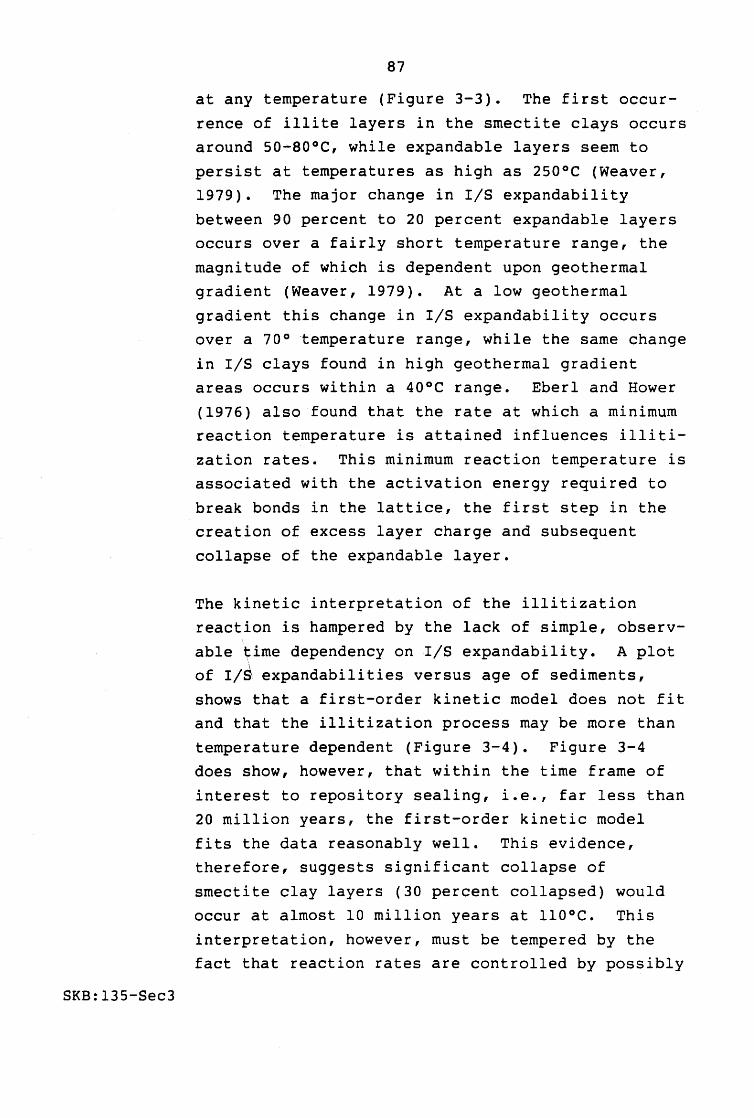
SKB:13S-Sec3
87
at any temperature (Figure 3-3). The first occur
rence of illite layers in the smectite clays occurs around 50-80°C, while expandable layers seem to
persist at temperatures as high as 250°C (Weaver, 1979). The major change in rls expandability
between 90 percent to 20 percent expandable layers occurs over a fairly short temperature range, the
magnitude of which is dependent upon geothermal
gradient (Weaver, 1979). At a low geothermal
gradient this change in rls expandability occurs over a 70° -temperature range, while the same change
in rls clays found in high geothermal gradient areas occurs within a 40°C range. Eberl and Hower
(1976) also found that the rate at which a minimum reaction temperature is attained influences illiti
zation rates. This minimum reaction temperature is associated with the activation energy required to
break bonds in the lattice, the first step in the creation of excess layer charge and subsequent
collapse of the expandable layer.
The kinetic interpretation of the illitization
reaction is hampered by the lack of simple, observ
able ~ime dependency on I/S expandability. A plot of r/~ expandabilities versus age of sediments,
shows that a first-order kinetic model does not fit and that the illitization process may be more than
temperature dependent (Figure 3-4). Figure 3-4
does show, however, that within the time frame of
interest to repository sealing, i.e., far less than 20 million years, the first-order kinetic model
fits the data reasonably well. This evidence,
therefore, suggests significant collapse of
smectite clay layers (30 percent collapsed) would
occur at almost 10 million years at 1100C. This
interpretation, however, must be tempered by the fact that reaction rates are controlled by possibly

88
50 - ... - -0 ..
I- 0 6 • ..
100 I- ~ 0 .. • • u 0 • 0 - • • ., .... ::J 150 I- .. -0
O • .... ., Q.
E • ., • .... .. • Hower et 01, 1976
200 l- • Perry and Hower, 1970
0 • Foscolos and Kodoma, 1974
o Boles and Fran ks, 1979 I-
~ Howard, 1981
250 I I I
0 25 50 75 100
0/0 Expandable Layers in lIS Cloys
Figure 3-3. Illite/smectite expandabilities in natural mixlayer clays versus the temperature of the formation in which they occur.
SKB:135-Sec3

en ... ~ ~ c
-.J
~ 0 ~
c 0 "'C c c 0. )(
W
~ 0
c::
89
2.4
110 0 C
2.0
1.6
1.2
0.8
¢
0.4 ~
o.o~ ____ ~ ______ ~ ______ ~ ______ ~ ______ ~ ______ ~ ______ ~ ____ __ o 10 20 30 40 50 60 70 80
Age, Millions of Years
REFERENCE· HOWARD, 1980
Figure 3-4. Illite/smectite expandabilities for selected Gulf Coast shales as related to age.
SKB:135-Sec3
SKB:135-Sec3
90
several physico-chemical factors, which are largely
unknown, and which may not pertain to seal environments in repository sites.
The chemistry of the interstitial fluids also plays
a significant role in the rates of illitization. Within intercalated sandstones and shales buried at
the same depth, with equal present-day temperatures
and equal thermal history inferred from sedimenta
tion rates, the r/s clays found in sandstone laminae are more expandable than those found in
adjacent shale laminae (Howard, 1981). This may be the result of greater salinity in the sand pore
waters. The presence of abundant Na+ and Ca 2+ in
the interlayer positions in the smectites effec
tively competes with K+ and retards the illitization reaction. Also, the greater organic acid
content of shales relative to sandstones, may enhance the breakdown of potassium feldspars and
increase the activity of potassium in pore water (Crossey et al., 1986). The potassium may increase
illitization rates in the shale. The transformation of smectite to a nonexpandable illite is also
the subject of many experimental studies. Results from this work reveal that the extent of reaction,
or the percentage of illite layers intergrown in the smectite, is dependent upon temperature, dura
tion of run, the nature of the interlayer cation, and fluid composition (Eberl and Hower, 1976;
Eberl, 1978). A K-beidellite (a montimorillonitegroup clay generally free of Mg or Fe in the
octahedral sites) glass formed from standard Ludox
gel procedures and reacted at temperatures between
250° and 400°C for up to nine months was altered to a mixed-layer illite/smectite clay. The extent of
reaction as a function of time was identified on a

SKB:135-Sec3
91
series of first-order-kinetic plots, so that the
slopes of the various isothermal lines are equal to
rate constants for the illitization reaction
(Figure 3-5). An Arrhenius plot of these rate constants against the inverse of temperature also
produces a straight line, the slope of which is a function of the activation energy. For a K
beidellite reacting to illite, an activation energy of 19.4 kcallmole is obtained, large enough to
suggest that breaking of Si-Al-O bonds within the lattice is a necessary step in the illitization
process (Eberl and Hower, 1976). This high activation energy probably represents the energy required
to break bonds in the tetrahedral layers so that A1 3+ can substitute for Si 4+ and increase the
negative structural charge.
The high temperature rate constants obtained in this experimental study can be extrapolated to
lower temperatures; consequently "run durations" measured in years can be obtained by means of the
calculated activation energies and the first order
Arrhenius equation (Figure 3-6). The rates thus
obtained are significantly faster than those observed in nature, i.e., at 90°C a smectite would
collapse to 20 percent expandable rls clay in less than one million years. By contrast, the Gulf
Coast Miocene sediments at 80°C have reacted only
to 50 percent expandable liS clay in 25 million
years. This contradiction led the authors and may subsequent investigators to conclude that the
degree of rls expandability is determined by
prevailing P-T conditions rather than the length of
time the clay had to react (Eberl and Hower, 1976;
Weaver, 1979).

~
:c c
-,;:J
0 c: 0 C
Q. )(
LaJ
~ 0
c:
92
2.2r-------------------------------------------------------------_
1.8
1.4
1.0
Beidellite Composition (First Order Reae tion)
-0.6
0.2 o ________________________________________ ~ ____ ~ ______ ~ ______ ~
o 80
REFERENCE: EBERL ANO HOWER, 1976
160
Days
240
Figure 3-5. Extent of reaction for a beidellite composition glass reacting to illite as a function of time (slope of each isotherm provides a rate constant for the illitization reaction), at 200 MPa (29,000 psi).
SKB:135-Sec3
320

93
1010r--------------_ .......
Ea = 19.6 kcal fMole
10~
o 20 40 60 80 100 120 140
Temperature,OC
REFERENCE.' EBERL AND HOWER, 1976
Figure 3-6. Relationship between temperature and the time for the illitization reaction of a beidellite composition glass calculated from experimentally determined rate constants (Figure 3-5), at 200 MPa (29,000 psi).
SKB:135-Sec3

SKB:135-Sec3
94
Eberl and Hower (1976) also recognize that the
presence of Na+, Mg 2+, and Ca+2 in the interstitial
fluids all have the effect of retarding reaction
rates, which would permit their results to be consistent with either a kinetic or equilibrium
interpretation. The effect of additional Na+ in
the interstitial fluids on reducing the rate of
silica removal from smectites illustrates the effect interstitial water chemistry can have on
illitization reactions (Lahann and Robertson,
1980).
Howard and Roy (1985) performed hydrothermal
alteration experiments using Na-montmorillonite and two artificial basaltic groundwaters (low K+; one
with Ca+ 2 , one without Ca+ 2 ). Their results
indicated the potential growth of nonexpandable
layers may be as high as 30 percent (150 0 C, 180 days) to 40 percent (250 0 C, 180 days), if K+ is
present in sufficient quantity. Other cations in solution appear to inhibit layer collapse and
formation of mixed layer (illite-smectite) clay. Reaction rates measured from these experiments are
faster than those extrapolated to lower temperatures based on the work of Eberl and Hower (1976).
The reasons for this result are uncertain, but may
include surface-area effects. The study recognized that in low permeability seals, for example, clay
mineral alteration rates may well be lower than in experimental systems where the supply and removal
of constituents is relatively uninhibited.
The energy required to dehydrate the interlayer cations found in smectites is inversely correlated
with rates of illitization in hydrothermal studies

SKB:135-Sec3
95
(Eberl, 1978). The dehydration energy available to
a clay corresponds to the negative structural charge created by substitution within primarily the
tetrahedral sheet; therefore, the low charge deficiency associated with smectites is insu,fficient to
dehydrate any interlayer cations and the layer remains completely expanded. As the layer charge
is increased by lattice substitution, cations with
low dehydration energies (e.g., potassium) are
dehydrated, and the layer collapses forming an
illite. The presence of other alkali and alkaline
earth cations with higher hydration energies in the
interlayer positions requires greater layer charge
deficiencies, or higher temperatures to collapse the expandable smectite layers. The implication
for natural clay assemblages is that the presence of these high hydration energy cations can effec
tively retard any illitization reaction when compared to a smectite with K+ already in the
inter layer positions.
Thermodynamic calculations indicate that smectites like other clays are stable at surface conditions
when compared to their component oxides in solution (Tardy and Garrels, 1974). However, when compared
to free energies calculated for illite, smectite is the unstable phase at surface conditions, and at
elevated temperatures. The implication is that smectites will eventually alter to illite under
diagenetic conditions even though the rates at which the reaction proceeds cannot be determined
from thermodynamic data.
Like illites, the variable composition of smectites results in a fairly diffuse and uncertain stability
field on various activity-activity diagrams.

SKB:135-Sec3
96
Smectites generally inhabit a field close to
amorphous silica saturation extending over a fairly
wide alkali/H+ ratio (Figure 3-7).
Smectites are ubiquitous at and near the earth's
surface in soil zones, on the ocean floor, as an authigenic cement in shallow-buried sandstones and
shales, and even in certain hydrothermal zones. However, in many of these cases, the smectites
under consideration are not pure phases, but
contain a small percentage of other clay layers
interstratified within the smectite packet. Closer investigation of many soil and diagenetic smectites
indicates that they contain a small percentage of nonexpandable layers. The only pure smectites
appear to be associated with freshly devitrified volcanic glass in recent bentonites, recent authi
genic cement in very porous sandstones, and recent hydrothermal alteration products. Given enough
time it is likely that even these examples would begin to incorporate other layers within the
smectite clay.
At this time there is no overall kinetic expression to explain the illitization reaction; at best there
are several elementary expressions which focus on individual steps, e.g., the release of Si 4+, and
the diffusion of K+. Despite the lack of consensus on whether illitization is a kinetic or equilibrium
phenomenon, the expected response of smectite clay
to the elevated temperatures anticipated in a
repository is for it to partially collapse to an
r/s clay. The extent of this collapse and the rate
at which it does this will be dependent on whether kinetic rates or equilibrium exert the greater
influence.

14
12
,.., ~ 10 LJ
"-.r c Z I..J
c:> o -1
4
2
Amorphous Si02 I Saturation --I
I I ,
No-Feldspar I , I I
I
u
c:> o ...J
18
16
8
6
97
Amorphous Si02 Soturotian~
I I
Mg -Chlorite I
5 4 3 -LOG [H4 Si0 4 J
I I
LJ
",.., + ~ u
12
2
Amorphous Si02 , Sotutation---1
K- Feldspar
Kaolinite
I I I I I I I I I I
543 - LOG (H 4 S i ° 4 J
REFERENCE GARRELS AND CHRISr, 1965
Figure 3-7. Stability relationship diagrams for several common low-temperature clay minerals calculated for the activity of several cations (K+, Na+, Mg2+, H+) against silica activity, at 25°C, 1 atmosphere.
SKB:135-Sec3

98
In summary, therefore, the longevity of smectite
clays appears to be dependent upon several factors.
Smectite stability is enhanced in silica-rich envi
ronments and low temperatures. Assuming that the kinetic model is correct, and utilizing the kinetic
diagrams produced by Eberl and Hower (1976), a
smectite would collapse to a virtually all illite
I/S clay at temperatures below 10QoC within 10 4-10 5
years. Note, however, that the results of Howard
and Roy (1985) suggest faster reaction rates may
pertain at these temperatures. The presence of
interstitial fluids high in alkali and alkaline
earth cations other than K+, and interlayer, or
exchange, cations other than K+ reduce the rate and
extent of illitization of smectites. The magnitude
of the retarding effect of other interstitial
cations in the pore fluids is uncertain at this
time. For example, a first-order kinetic model
appears to fit Gulf Coast data relating the extent
of illitization with the age of sediments. This model predicts only about 10 percent collapsed
layers would occur in smectites at 110°C at the end
of 10 6 years. Apparently, many environmental
factors (heating rates, maximum temperature, and
fluid chemistry) strongly affect the illitization
reaction under natural circumstances and could
control the stability of smectite clay minerals
under repository conditions. Of concern, though,
is the recognition that many of the physical and
chemical properties of even a slightly illitic I/S
clay may vary from those associated with a pure Na
bentonite.
3.3.2.4 Effects Due to Radiation
SKB:135-Sec3
Incorporation of clays in seals, such as fracture
seals near waste packages, that are intended to

99
contact and sorb long-lived radionuclides requires
that the clays remain stable and functional for
long time periods. The exposure of the clays to
ionizing radiation, particularly the radiation from sorbed radionuclides, may also decrease their long
term stability.
A study by Haire and Beall (1979) was restricted to
the morphologic effect on kaolinite and palygor
skite (attapulgite) by a strong alpha radiation
* source sorbed on the clays. Morphologic effects
(porosity, pitting, fragmentation of plates, and
clumping of rods) were evident, and the rate and
severity at which they appeared were directly related to the strength of the alpha source. Clays
loaded to only a small fraction of their sorptive
capacity remained apparently unchanged after
several weeks, but with radionuclides sorbed to
capacity, the clays rapidly showed evidence of
disruption. In addition, the palygorskite which has a far greater sorptive capacity, showed much
greater radiation damage in a given time. An
important conclusion of this work was that the
sorption of Es-253, as measured from the radio
nuclide concentration in brine carrier fluids,
remained unaffected by the disruption of the
sorbent. It must be noted, however, that the
sorption mechanism under these conditions was not
determined. The Es may be retained on the clay, or
may occur in an unknown insoluble and centrifuge
able phase. The experiment provides no evidence
*Es-253, 6 x 10¹⁰ alpha/minute-microgram or 6.6MeV alpha radiation; this alpha source is very high with respect to decay energy of individual radionuclides in waste inventories, but not large with respect to the decay energy of the entire waste inventories.
SKB:135-Sec3

SKB:135-Sec3
100
for either possibility, and the relevance of this
result to other clay minerals and radionuclides is
unknown.
The potential for crystallographic, and thereby
behavioral changes in clays due to irradiation by
sorbed sources may be estimated by exposure of clay
materials to radiation from external sources. The
morphological effects of an electron beam and gamma
irradiation on quartz and kaolinite have been
investigated (Spitsyn et al., 1980). The radiation
treatment (Co-60, 2.6 Mrad gamma/hr) resulted in
the formation of clumps from an initially evenly
dispersed and evenly size-distributed kaolinite sample. The electron beam (accelerating voltage,
Eo = 100 kev, time = ?) caused surficial pitting of the kaolinite crystals, and the clay crystals
became anhedral. Nonetheless, no structural
changes were apparent in the X-ray diffraction of
the sample. A volume increase in the surface layers of the kaolinite may have occurred due to
irradiation, although the causative mechanism for this phenomenon was not determined. Krumhansl
(1982) also showed no crystallographic changes
occurred in smectite (from bentonite) exposed to
1010 rads of 60Co gamma radiation.
No firm conclusions can be made based upon existing data for the irradiation effects on clays. Appar
ently, clays are not immune to crystallographic disruption from strong radiation sources. Long
term effects due to irradiation by nuclides in a
repository and the effects on the functional pro
perties of a clay seal or backfill are currently unknown.

101
Other components in earthen seals. Other
components of an earthen seal material may also be
altered under repository conditions. Quartz, for
example, is likely to occur in such materials
either as an accessory mineral in bentonite or as
noncohesive additive to clay-rich materials. At
low temperatures and pH between 4 and 10, quartz is
very stable. Increased temperatures will increase
quartz solubility; however, Pusch et ale (1985),
explain that temperatures up to 100°C should cause
little alteration of seal materials properties due
to quartz dissolution and subsequent silica precip
itation upon cooling. Long-term transport of
silica from a fracture seal at elevated tempera
tures may increase porosity in the seal. This
effect on seal integrity has not been widely
examined.
3.4 SUMMARY OF PROGRAM OF RESEARCH FOR PRIORITY SEAL MATERIALS
SKB:135-Sec3
The priority seal materials have been selected
because sufficient evidence has been generated to
show they can be effective seal materials, and
because any uncertainties they present can be
surmounted through practical research programs.
Sealing issues, however, require resolution before
final seal designs can be devised for a nuclear
waste repository.
Table 3-3 summarizes the sealing issues and a
proposed approach for addressing issues for the
candidate materials. The issues may be resolved
through:
• Laboratory testing • Field testing • Analytical studies and modeling.

102
Table 3-3. Summary of general issues for priority grouting materials for fracture sealing
Issue
(1) Define materials performance requirements.
(2) Select starting materials and prepare mix design(s); characterize selected materials.
(3) Select key materials properties and determine materials performance with respect to performance with respect to performance requirements; optimize materials properties.
SKB:135-Sec3
Proposed Approach
Perform modeling of seal performance under several release scenarios including site geology, site hydrology, site geochemistry, repository design and (in situ conditions) site performance regulatory criteria (if any) to determine seal performance requirements for hydraulic conductivity, retardation potential, performance longevity, mechanical properties. Performance requirements are site specific based on (1), select cementitious materials and additives likely to produce desirable characteristics using test data and industry literature; priority should be given to inexpensive, available materials.
Determine limited range in which design parameters may be varied from literature. Perform trial mixes and preliminary laboratory tests (e.g., viscosity, penetrability, bleed, strength, hydraulic conductivity); select mix(es) based on (1) for further study.
Select key properties of grout based on (1) and devise test program. Perform standard laboratory tests to evaluate properties of selected materials.
Materials properties may include:
Viscosity
Bleed
Penetrability/set time
Hydraulic conductivity

103
Table 3-3. Summary of general issues for priority grouting materials for fracture sealing (continued)
Issue
(3) (Continued)
(4) Establish longevity requirements for grout and determine materials performance longevity (stability).
(5) Determine effects of grout material, emplacement, or alteration products on radionuclide mobility.
SKB:135-Sec3
Proposed Approach
Interface hydraulic
conductivity
Unconfined/confined compressive
strength
Thermal expansion
Tensional strength
(flexural)
Shear strength/erodability
Based on (1), establish the longevity requirements for grout performance; longevity requirements will be sitespecific and probably specific to individual seals, materials, seal functions, or locations within the facility; estimate long-term compatibility to performance of grout in host environment through real-time and accelerated laboratory testing of grout materials; perform geochemical modeling, thermodynamic and kinetic calculations to estimate types and rates of materials alteration and consequences on performance; host environment includes host rock, ground water, waste, adjacent seals, backfills, waste package, temperature and pressure conditionse
Perform laboratory solubility and sorption testing using selected grout materials, alteration products (4), and altered ground water compositions and key radionuclides or analogs.

104
Table 3-3. Summary of general issues for priority grouting materials for fracture sealing (continued)
Issue
(6) Confirm material's emplaceability and emplacement equipment; optimize grout emplacement.
SKB:135-Sec3
Proposed Approach
Perf9rm field tests in test facilities comparable to repository conditions; determine:
• Grout delivery rates • Penetration of grout
as a function of grout type, equipment, nature of fracture (e.g., aperture, tortuosity, etc.); perform post-test analysis (including destructive tests) to determine:
• Uniformity of grout penetration
• Permeability of treated fractures.

SKB:135-Sec3
105
Laboratory testing may include bench scale tests.
Table 3-3 lists the potential approaches that
currently appear most significant. Final selection
of technical approaches to issue resolution will be included in future research planning activities.
Test planning will include equipment and test
location selection, optional methods evaluations,
and test/analysis procedure development.
The technical approach to seal materials research
and the priorities for testing and analyses are
individual to specific sealing programs, sites, and
in situ conditions. The approach shown in Table
3-3 is generic, but notes where site specific matters are most critical; e.g., definition of seal
performance requirements, definition of longevity
requirements, and tests to be performed. The
overall approach, however, should apply in all seal
material development programs:
• Determine performance requirements of grouts
• Select materials and formuli that appear likely to meet performance requirements, and characterize starting materials
• Select key (or priority) materials properties and determine materials performance; optimize materials performance with respect to performance requirements
• Establish longevity requirements for seal performance and determine materials longevity (stability) under in situ repository conditions
• Determine any effects of grout materials, their emplacement, or alteration products on radionuclide mobility
• Confirm materials emplaceability and emplacement equipment performance in situ and optimize grout emplacement.

106
3.S EMPLACEMENT CONSIDERATIONS
3.5.1
SKB:135-Sec3
Materials performance characteristics primarily
dictate seal materials selection and design. In
addition, emplacement considerations and emplace
ment methodology may also affect the design and
selection of seal materials. The special require
ments of grouting fine fractures in rock have been
summarized by Pusch et ale (1985), Pusch (1986),
Gray (1986) and references cited in those reports.
This section briefly summarizes the effects of
emplacement considerations on materials selection
for fracture sealing. Emplacement methods are
described in Section 4.
Cementitious Materials
In general, the grain size of particulate grouting
materials must be about 0.1-0.4 the size of the
aperture of the fracture to penetrate the fracture
successfully (Karol, 1982b). Common cementitious
grouts have been shown to penetrate into fractures
only a small fraction of a meter if the fracture
aperture is 0.3 rom or smaller (Pusch et al., 1985).
Both the Swedish (Pusch, 1986) and the Canadian
programs (Gray, 1986; Ballivy, 1986; Aitcin, 1986)
are investigating the performance of finer grind
cements such as reground sulphate resistant
portland cements and Geochem, microfine grouting
material (Me-SOD) that has penetration abilities
similar to chemical grouts (Shimoda and Ohmori,
1982).
Expressing the fineness of cements in terms of
specific surface area, as measured by the Blaine

SKB:135-Sec3
107
permeameter, Gray (1986) described sulfate
resistant portland cements and expansive cements
that have been reground to yield cements with
finenesses of 600 to 670 m2/kg, respectively (normal value -300 m2/kg). The influence of the
finer grain size on the rheological and setting
properties of cement/water mixtures (Aitcin, 1986)
shows that fine-grained cements tend to have higher
viscosity for a given w/c (or higher w/c is
required to produce a low viscosity paste with
fine-grained cements). This effect is pronounced
with Geochem grouting material, but not as
pronounced in finer-grained samples of Type 50
(ASTM Type V) or API Type K (expansive) cements.
The w/c of the Geochem mix was about 40-60 percent
higher (0.72) than in the portland cement mixes (0.45 to 0.55, without silica fume) for 12 second
flow cone time. In general, the finer-grained
cements tend to set (initial and final) faster than
coarser grinds of the same cement based on mixes of approximately the same initial viscosity. Geochem,
however, does not fit this general pattern, being
slower to set than the reground portland cement
materials, although it is considerably finer
grained. Aitcin (1986) noted that regrinding has a
tendency to cause mineral segregation because of
the variable hardness of the particles.
Penetration of grouts generally increases as the
viscosity of the grout decreases. In cementitious
slurries, viscosity can be reduced by increasing
the w/c ratio. If fluid, high w/c grouts are used, bentonite may be added to enhance the homogeneity
of a cementitious grout suspension by providing a
higher density fluid, and it will help to reduce
bleed ("stabilization").

SKB:135-Sec3
108
As described earlier, however, the w/c ratio
affects several properties of the grout and should
be kept as low as possible to maintain:
• Low hydraulic conductivity • High strength • High bond strength • Low bleed • Low shrinkage • Long-term materials stability and
performance.
Materials with w/c ratios of about 0.5 become
difficult to inject in fractures finer than about
0.5 rom aperture (Pusch, 1986) using standard
grouting methods because the viscosity of the paste
becomes relatively high. Table 3-4, for example,
shows the viscous properties of neat cement grouts
as a function of w/c. Below w/c = 0.5, viscosity
increases rapidly. Much thinner grouts are more
commonly used in grouting practice e.g., w/c = 3 to
10, (Pusch, 1986). Studies have been completed by
Lau and Crawford (1986) which show that two
placticizers, naphthalene sulphonate (NS-200) and
sulphonated naphthalene formaldehyde concentrate
(Lomar-D), will decrease the viscosity of rapid
hardening portland cement at w/c < 0.6. The
homogeneity of the mixtures is also improved. The
data indicate that NS-200 and Lomar-D are required
in proportions of up to 7.5 percent by dry mass of
cement to be effective. Tests have been completed
which show that a third, lignin-sulphonate based
superplasticizer, trade name Dica1, will be
effective with sulfate-resistant portland cement in
proportions of less than one percent by dry mass
cement (Ballivy, 1986). Studies are in progress to
examine the effects of this material on grouts in
their fresh and cured states (Gray, 1986).

109
Table 3-4. Shear strength and plastic viscosity of neat cement grouts
3.5.2
SKB:135-Sec3
w/c 0.3 0.4 0.5 0.6 0.7 1.0 2.0 5.0
10.00 20.00
Shear Stre~gth (dynes/cm )
3840 670 230 120
70 29 10 5.3 4.3 3.9
water 0 Ref: Littlejohn, 1982
Plastic Viscosity (poise)
4.03 0.90 0.37 0.20 0.13 0.06 0.025 0.014 0.012 0.011 0.010
Although lower viscosity grouts show improved
penetration and rate of delivery to a fracture, as
viscosity is decreased there is a well-documented
tendency for the grout to flow into a fracture
along irregular fingers. Low viscosity grouts tend
to be unable to push water out of the fracture but
to mingle with it. The void space in the fractures
is poorly filled and the grouting proves
ineffective. Thus, there is a practical limit to
reducing the viscosity of grout as a means to
penetrate saturated fractures.
Earthen Materials
Clay grouts generally incorporate only fine-grained
particulates. The majority of the particulates are
clay size unless admixtures, such as cement or
silt, are present. Clay grouts and chemical grouts
(pure solutions that usually contain no particu
lates) penetrate fractures finer than 0.3 rom more

110
effectively than ordinary cement grouts. Clay
grouts require water contents on the same order as
their liquid limits to be successfully emplaced by
standard grouting technology (Pusch et al., 1985). For Na-bentonite, the water content will be
about 300 wt% or more to achieve the required
liquidity. Water content in excess of the liquid
limit reduces viscosity of bentonite grouts and
makes them easier to emplace. High water contents,
however, tend to exhaust the swelling capacity of
the smectites in the bentonite, and the hydraulic
conductivity of the resultant fracture seals tends
to be higher than in clay grout seals formulated
with lower water contents. The erosion resistance
of these "low density" (high water content) clay
grouts is not as satisfactory as denser clay grouts because the thixotropic property (the ability to
set or gel and increase in shear strength when
undisturbed) of the clay grout is also dimin
ished. The high water content limits the development of an extensive flocculated clay fabric
that would tend to hold the clay particles
together. Means to overcome erosion of clay grouts
are discussed in Section 3.2.2
3.6 FORMULATIONS OF PRIORITY MATERIALS
SKB:135-Sec3
Section 2.4 includes a summary of performance
criteria for the materials for sealing fractured
rock in a mined nuclear waste repository. Based on
these criteria, priority materials were selected
from among several possible materials for use in fracture sealing and described in greater detail.
These materials have been ~elected for priority study and for use in field and laboratory tests.
The priority seal materials are:
3.6.1
SKB:135-Sec3
III
• Cementitious materials • Earthen materials, particularly bentonite.
Cementitious Materials
Cementitious materials offer several valuable
properties to repository sealing. These are:
• Low permeability
• Potential for long-term performance, if emplaced under good quality control and not exposed to environments known to degrade these materials
• High strength or, with proper mix design, a degree of flexibility.
Priority cementitious grouts include the following
components:
• Portland cement or a reground portland cement or other fine-grained cement product
• Pozzolan, such as silica fume
• Plasticizer
• Expansive additive, and other additives, as necessary.
The type of cement used will depend on local
conditions; e.g., if sulfate or acid conditions are
present. For grouting large-aperture fractures,
ordinary portland cement is expected to be servic
able. For fine aperture fractures, ultrafine
grained cements will be required. In order to
produce a material with adequate hydraulic conduc
tivity and strength, pozzolanic additives and low
water:cement ratios appear necessary. Plasticizers
will help reduce the viscosity of grouts formulated
with low water:cement ratios. Expansive additives
SKB:135-Sec3
112
will help preserve a strong, low hydraulic
conductivity bond between the grout and the host
rock by preventing shrinkage due to curing and
drying. Other additives, such as accelerators, air
entrainment additives, or clays may be required to
meet specific performance or emplacement needs.
The chemical longevity of cementitious materials
appears to be enhanced by the use of pozzolanic
additives, low water:cement ratios, and high
quality emplacement techniques that help reduce the
porosity and permeability of the final material.
The rate and amount of leaching from cementitious
materials tends to be lower when porosity and
permeability are low.
The longevity of cementitious grouts can be further
assured if the emplacement environment is well
characterized and the material design is adjusted
for conditions known to limit the service lifetime of portland cement-based materials. These condi
tions include high sulfate, acid, CO2, or elevated
temperatures. For example, poorly crystalline
C-S-H phases in cementitious materials cured at low
temperatures undergo phase transformations around
100°C which may increase the porosity of the
material and thereby reduce the longevity of the
material. This factor may be offset somewhat by
the greater thermodynamic stability of C-S-H phases
resulting from the transformation and possible
increased strength of the material due to the
transformation of C-S-H phases in the cementitious
gel to more crystalline C-S-H phases or
tobermorite.

3.6.2
SKB:135-Sec3
113
The mechanical stability of cementitious materials
is optimized by the use of pozzolans, high strength
aggregate (if any), and low water:cement ratios.
Cementitious materials can withstand the compressive stresses that are likely to occur in situ in a
mined nuclear waste repository in crystalline rock
and should be well-suited under these conditions.
Cementitious materials and their bonds with host
materials tend to be weakest under tension.
Thermal or mechanical stresses that place tension
across a bond in a fracture seal, for example, may
cause the fracture to reopen after grouting with
cementitious grout. The cement has no ability to
re-heal or re-cement after fracturing. Thus,
cementitious grouts appear least suitable under
tensile stress.
Earthen Materials
Earthen materials, particularly clays are considered widely applicable, high-priority
materials for repository sealing. Clays possess many favorable properties that support their
priority consideration. The priority earthen
materials for study as fracture sealing grouts
include:
• Commercial Na-bentonite
• Bentonite with small proportions of cement and fine- and/or coarse-grained, noncohesive and noncementitious admixtures.
Na-bentonite provides several desirable properties; e.g., low hydraulic conductivity, swelling capacity
and self-healing of fractures, and emplaceability.
For example, a clay grout consisting of bentonite
(substantially the Na form) and water, at its

SKB:135-Sec3
114
liquid limit (sufficient water to inject the mater
ial), achieves hydraulic conductivity of about 10-7
- 10-8 cm/sec (Chan, 1982; Pusch et al., 1985).
Higher water content, or the Ca form may result in higher hydraulic conductivity grout. The addition
of small amounts of cement or coarser grained
materials may impart greater erosion resistance to
the bentonite, perhaps at the sacrifice of
emplaceability in the finer aperture fractures.
There appears to be little evidence that
substantial alteration of the crystal structure of smectites will occur under repository conditions
that do not greatly exceed 100°C or include
extremely high or low pH groundwater. Cation
exchange in sodium smectite is likely to occur if
groundwater contains cations, such as calcium, with
a strong preference relative to sodium for exchange
sites. The introduction of calcium in exchange
sites will increase permeability of the clay but may improve its mechanical properties, particularly
with regard to erosion under high hydraulic gradients.
Clay-poor earthen materials can possess substantial
confined compressive strength and the addition of substantial clay fraction may decrease the strength
of the material. The addition of clay, however, imparts plasticity to the material, and, in the
case of bentonite, a fracture-healing ability upon
contact with water. Thus, clay-rich seals may
resist the effects of in situ stresses by plastic
deformation or self-healing any fractures that
occur (e.g., during a desiccation period) by
swelling upon the reintroduction of water (Pusch et
al., 1985).

3.6.3
SKB:135-Sec3
115
Investigations (e.g., Yong et al., 1986) have shown
that other pure clay minerals (e.g., kaolinite and
illite) and mixtures of clay minerals and other clay sized materials (materials such as rock flour
with particle sizes of less than two microns) can possess hydraulic conductivities as low as 10-8
cm/sec and through sorption can retard the rate of
radionuclide migration. The results s~ow that
mortmorillonite generally sorbs radiorluclides more
efficiently than most other minerals. These
material studies indicate that, by virtue of lower
hydraulic conductivity, higher sorptive capacity
for radionuclides, lower chemical diffusion
coefficients, and an ability to swell, bentonite
appears to be the most favored clay mineral for
sealing fractured rock near a nuclear waste
disposal vault.
Description of Likely Compositional Ranges
Table 3-5 contains a summary of the materials and compositional ranges of materials that are being
studied or have been recommended for further study
in participants' sealing research programs. Most
data are derived from the Swedish and Canadian
programs which have the most advance research
programs for fractured rock sealing. Several materials in addition to those listed have been
mentioned in terms of fracture sealing, particularly cements and additives for cement. The
references shown in the Table include lists of
these alternate materials.

Ul ?i: tIl .. ~ VJ un
~ Table 3-5. Compositional ranges of candidate sealing materials in current sealing programs m n VJ CEMENTITIOUS GROUTS
Cement 1. Class A (Type I, CSA Type 10)
2. Class B (Type II, CSA Type 20)
3. Class C (Type III, CSA Type 30)
4. Class H (standard oil well cement)
5. Class K (expansive cement)
6. Other sulphate resistant portland cement (Type V, CSA Type 50)
7. Portland cement, regrind
8. MC-500, fine grained grouting cement
9. Gypsum-free cement
10. Geochem (microfine portland cement + slag)
Reference Gray, 1986
Gray, 1986
Gray, 1986; Roy et al., 1983
Roy et al., 1983
Gulick, 1978; Ballivy, 1986; Aitcin, 1986
Gray, 1986; Ballivy, 1986; Aitcin, 1986
Gray 1986; Ballivy, 1986; Aitcin, 1986
Gray, 1986; Ballivy, 1986; Aitcin, 1986
Pusch, 1986
Ballivy, 1986; Aitcin, 1986
.......
....... 0'\

Ul ~ IJj
I--' W U1 I
Ul m n w
Table 3-5. Compositional ranges of candidate sealing materials in current sealing programs (Continued)
Additives
1. Pozzolans a. Silica fume b. Silica flour (with lime)
2. Plasticizers a. Napthalene sulphonate
b. Sulphonated napthalene formaldehyde
c. Lignin sulphonate (Dical)
3. Accelerators (as needed) CaC1 2
4. Expansive additives (not including Type K cement)
aluminum powder gypsum, hemihydrate
5. Clay a. Na-bentonite b. Ca-bentonite
water:cement ratio
CEMENTITIOUS GROUTS (Continued)
Proportions
0-10 wt%
up to 7.5% by dry mass up to 7.5% by dry mass <1% by dry mass
1-3% by dry weight
0.005 wt % 5-10 wt %
2-5% cement weight
0.6 - 0.4 (generally >0.5)
Reference
Ballivy, 1986; Aitcin, 1986 Pusch, 1986
Gray, 1986
Gray, 1986
Gray, 1986; Ballivy, 1986; Aitcin, 1986
Gray, 1986
Ballivy, 1986; Aitcin, 1986 Roy et al., 1983
Pirhonen, 1986 McCombie and Knecht, 1986
Pusch, 1986
......
...... '-.I

U)
~ OJ
~
w Table 3-5. Compositional ranges of candidate sealing materials in current sealing programs ~ (Continued) U)
ro ~ EARTHEN MATERIAL GROUTS
A.
B.
c.
A.
B.
Bentonite grout Na-bentonite Sand (-50)m quartz) Water
Bentonite grout Na-bentonite Water
Bentonite grout Ca-bentonite Water
PROPORTION
50 - 75% 25 - 50%
REFERENCE Pusch, 1986
150 - 400% optimum (500-600% may be required)
100% <500%
100%
Pusch, 1986
Pusch, 1986
EARTHEN/CEMENT MIXTURE GROUTS
PROPORTION REFERENCE Clay-cement grout
Commercial Na-bentonite Quartz filler (-50)m) Cement (-75)m, low alkali) Water
Commercial Na- or Ca-bentonite CSA Type 10 cement Silica fume Water
Silt grout Silt Cement Clay
75% 15% 10% 400%
15 - 34% 5 - 8% o - 2% 58 - 80%
75 - 95% 0.5% by weight 0.2 - 0.05%
Pusch et al., 1985
Chan, 1986
Pusch et al., 1985
~ ~ co

Ul !A! tIl
~ W U1 I
Ul CD () w
Table 3-5. Compositional ranges of candidate sealing materials in current sealing programs (Continued)
CHEMICAL GROUTS
NOTE: Not recommended in Canadian, Swiss, and u.S. Programs.
A. Sodium silicate grout Dynagrout (aluminate +
NaOH solution) Sodium silicate Water (neutral to slightly acid)
2.2%
20.0% 77.8%
Pusch, 1986 ........ ........ \D

4
120
EMPLACEMENT TECHNIQUES
Emplacement of seals, including materials handling
and transport, and quality control of the emplaced
material, will be key to the successful operation
and closure of a repository. Considerations for
emplacement include:
• Emplacement technology that can be used with priority sealing materials to achieve adequate seal performance
• Practical limits on emplacement technology
• Quality control of emplaced seals.
The literature related to emplacement of seals, in
general, is extensive. A number of references
related to general seal emplacement methods are
cited by ONWI (1980) and Meyer and Howard (1983).
This discussion will review research on grouting
fractured or damaged rock for nuclear waste
repositories. More extensive reviews of grouting
technology, in general, are found in Pusch et ale
(1985) and Gray (1986) and references cited in
these reports.
4.1 FRACTURE SEALING METHODS
SKB:135-Sec4
The general purpose in sealing or grouting frac
tures in host rock for nuclear waste repositories
is to restore the bulk permeability of the host
formation to a value close to its undisturbed
permeability for a specified (presumably long)
period of time. Grouting will require that
materials possessing certain desirable character
istics will be emplaced in fractures, some of which
may have very narrow apertures (0.1 rom or less).

SKB:135-Sec4
121
To meet the overall goals of the grouting opera
tion, the materials will possess low hydraulic
conductivity and a high degree of chemical and
physical stability in the emplaced environment. Thus, the emplacement technique must operate using
selected materials (priority sealing materials),
causing no additional damage to the host rock, and
meeting the space, logistical, and practical
limitations likely to prevail in a mined nuclear
waste repository.
The fracture grouting methods that may prove useful
in repository sealing include:
• Injection of grout slurry at high pressures • Electrophoresis • Dynamic injection.
Pressure Injection. Injection of grout slurries
under pressure can be applied to both priority grout materials, cementitious and clay grouts, as
well as to chemical grouts, and bitumen currently
considered lower priority material groups. Usually
grout is introduced into the fractures in the rock
under pressure through a packed-off interval of a
borehole or other opening. The grouting operation requires mixing and blending tanks, pumps, a power
source, packers, and connecting hoses, valves and
fittings [see Department of the Army (1973) for
illustrations and descriptions].
The applied pressure is usually in the range of 0.5-2.0 MPa (Pusch, 1986). The pressure must
overcome any hydraulic pressure on groundwater
residing in the fracture and push the water from
voids that will be filled by grout. The applied pressure provides the shear stress that forces the
grout to flow through a tortuous fracture. Pres
sure can be increased to improve the penetration of

SKB:135-Sec4
122
grouts, including coarse-grained materials. The
maximum pressure that can be applied varies from
site to site depending on in situ confining
stresses (e.g., Pirhonen, 1986), but excess
pressure will result in increasing the aperture of
existing fractures or increasing the number of
fractures in the rock being grouted. The
probability of damaging the host rock severely
limits the maximum pressure that can be applied.
Electrophoresis. Electrophoresis has been studied
by Pusch (1978c) and Pusch et ale (1985) and may be
effective in emplacing clays in fine fractures in
rock. The principal of electrophoresis is to drive
clays through fractures under a static electric
potential. Laboratory tests proved good penetra
tion (up to one meter) of montmorillonite through
irregular fractures using electrophoresis (Pusch, 1978c). A field test (Pusch et al., 1985) proved
less successful, with variable sealing of frac
tures. A key practical disadvantage to electro
phoresis, as presently configured, may be the need
to drill additional holes for electrodes which may
present sealing problems of their own. Electrophoresis may be effectively applied under select
circumstances but continued research appears
necessary.
"Dynamic Injection". Recent reports by Pusch
(1986) and Pusch et ale (1985), describe a novel injection technique named "dynamic injection" in
which a constant pressure is placed on the grout
slurry, not unlike ordinary pressure grouting, on
which are superimposed shear waves induced by
percussion. A similar technique, using ultrasonic
waves, has been demonstrated in shallow environ
ments at a quary in Japan (Kameda, 1983). The

SKB:135-Sec4
123
dynamic injection technique can be applied to
cementitious and clay grouts and is designed to
overcome the penetration limits caused by the high
viscosity of grouts that otherwise possess desirable properties. The shear imparted to the
grout by the percussion reduces the tendency for
cementitious and clay grouts to thicken during
injection into the fracture, and helps to keep silt
size particles suspended.
The method has been laboratory and field tested.
Figure 4-1 shows the grouting operation configura
tion of Pusch et al. (1985). These tests have
demonstrated that clay grouts containing water at the liquid limits and possessing good thixotropic
behavior, high swelling capacity, low hydraulic conductivity, and some degree of erosion resistance
can penetrate apertures as small as 0.1 rom several decimeters or even meters. In the same series of
tests, cementitious grout prepared at a low water:cement ratio (0.5) was emplaced with
penetration in excess of 0.5 m.
Pusch et al. (1985) have field tested the method using sodium bentonite prepared at its liquid
limit. These tests, in granite at Stripa, proved the method to be effective in sealing fractures.
As expected, however, at in situ high hydraulic gradients, the clay grout was not effective as a
barrier to groundwater flow, probably due to
erosion.
Special Methods to Produce Effective Fracture
Seals. Special means to produce effective fracture
seals entail using emplacement techniques such as
pressure or dynamic injection with a sequence of
materials designed to overcome potential problems
currently recognized in sealing with one material

,--------- ------,' " " , \ \ \ , \
124
The hOlt (1) ts 'frst 'flltd .tt~ tfte cl" slu~~y ~v
us. of the D.cktr tube (2) It Th. fle.ibl1 tube Cl) '''011 t"e 1'''9' C1lfndt~ witi'I
thl cllY slurry h .ttldltd .ftCI t ",I SUttc O"~S$U"'!
fs 1D0111d
c: 'trcuss tOft ".-et"f"9
cI V.lve (4) closld. 'nJecttOfl de"'ct ~"'''ed
Pusch et al., 1985
Figure 4-1. Principle for injecting rock with "dynamic injection technique".
SKB:135-Sec4
A) percussion drilling machine, B) steel cylinder, C) slurry container, E) transducer F) valves, G) air pressure, I) borehole, 2) packer, 3) high-pressure hose, 4) valve

125
or type of material alone. For example, Tokonami
(personal communication, 1987) describes current
efforts to emplace cementitious grout which would
be followed by a clay (bentonite) grout in a single
fracture seal. The cementitious grout provides
high erosion resistance during the resaturation
phase of the repository during which hydraulic
gradients through fractures may be greatest. Over
the long term the cementitious grouts may be
chemically altered, (for example, by dissolution)
and become nonfunctional, or in situ stresses may
cause fracturing of the grout, particularly if
tensile stresses occur. At the time when the
cementitious grout becomes ineffective, hydraulic
gradients will presumably be reduced to almost
negligible values; i.e., following resaturation of
the repository. Thus, the clay grout, with its
lower erosion resistance but good hydrologic,
chemical stability, plastic, and fracture healing
properties, will provide long-term, effective
sealing. Research in specially-designed emplace
ment of fracture grouts is ongoing in most of the
participants' repository sealing programs.
4.2 LIMITATIONS IMPOSED BY REPOSITORY DESIGN
SKB:135-Sec4
Several of the limitations on fracture seal
emplacement have been briefly mentioned in previous
sections. Other considerations that bear on the
practicality and selection of emplacement methods
are imposed by the repository (or test facility)
design itself. These are briefly described in this
section. The significance of these considerations
will vary from one facility to another.
The repository design will impose limits on the
available space for grouting equipment and, if

126
necessary, drilling equipment. This is not
expected to present serious consequences on grout
emplacement methods mentioned in Section 4.1.
These methods have been employed in tunnels, either in industrial/civil projects or in repository
sealing programs (Pusch et al., 1985). Space
limitations have not affected the equipment
selected, the methods utilized, or the results of
the grouting operations. Subsurface drilling
equipment is standard in mlnlng and tunneling, and
drilling should not be severely affected by space
limitations.
Grouting operations that produce excessive heat or
require high energy input present practical
obstacles. Repository design incorporates
ventilation and power systems, and these limit the
allowable heat output and power requirements of the emplacement methods. Experience has shown these
considerations have not affected grouting operations; however, extensive grouting programs have
not been performed in repositories or in repository
test facilities. Full-scale grouting operations
will take these considerations into account.
4.3 EMPLACEMENT TEST CONSIDERATIONS
SKB:135-Sec4
Practical issues must be identified and resolved
prior to performing full-scale in situ tests of
fracture sealing technology. Items to be included
are:
• Selection of injection technique
• Selection of fractured rock type and location
• Selection of candidate materials for each test

4.3.1
SKB:135-Sec4
127
• Space requirements
• Thermal considerations
• Monitoring of injection test
• Post-test sampling concepts.
A key preliminary activity will entail selection of
the most suitable grout injection technique(s), and
operation principles, and to construct or obtain
practical equipment. Pilot tests may be employed to verify the suitability of the selected injection
technique{s). Pilot tests may be followed by large
scale sealing tests in waste deposition holes,
fractured rock zones, and in seal zones.
The selection of suitable locations for the sealing test is of particular importance. More than one
test site may be necessary to verify methods and
procedures under a variety of conditions, such as
underground design, in situ stress and hydrologic
conditions, rock type, and the nature of the
fractures. The number of repeat tests required to
assure the grouting operations will result in
reproducible seals and seal performance will be determined.
Selection of Injection Techniques
A strong emphasis of early testing is the develop
ment of effective grout techniques. Thus,
conventional injection (grouting) which implies
that the grout is pressed into fractures under a
static pressure in the range of 0.5-2 MPa, is not
sufficient to bring in cement or clay suspensions
in fractures with a physical aperture that is
smaller than 0.1 mm. This aperture may represent
the upper end of the spectrum of fracture widths

4.3.2
SKB:135-Sec4
128
that will be dealt with in sealing fractures
intersecting waste emplacement boreholes in high
quality granitic rock. To some extent this can be
solved by reducing the viscosity of the grout, but
its sealing properties may thereby become
insufficient.
A very promising way of improving the penetrability
of cements and clays as well as other particulate
materials is the "dynamic injection technique",
described by Pusch et ale (1985) and summarized in
Section 4.1, or the similar ultrasonic vibration
method described by Kameda (1983). Both procedures
are based on the principle in which vibratory
motions are superimposed on the static injection
pressure and each has proven effective in emplacing
cementitious and clay grouts in narrow apperture
openings. At this time both methods merit
consideration in injection technology development.
Selection of Fractured Rock Type
The repository sealing program will determine which
types of fractures are significant to meeting
repository performance goals and determine
locations for performing tests within individual
facilities (candidate repository or test
facility). Each program may concentrate on
different grouting requirements; e.g., sealing of
major water-bearing fractures intersecting waste
emplacement boreholes. An example of such
fractures is shown in Figure 4-2.
In addition, grouting of crushed rock zones that
are intersected by repository tunnels is also of
great importance if required as part of the
temporary sealing to prevent severe water inflow in

TOP VIEW
• ! o
.... ,,..--·-N .-,
129
PERIPHERY
N
""7'.'
. ¥ ;;
•
. w a ~
•
. i
Pusch et al., 1985
Figure 4-2. Major fractures in heater hole no. 1 of the Buffer Mass Test at Stripa
SKB:135-Sec4
If

4.3.3
SKB:135-Sec4
130
the construction period or if required in permanent
seal designs as part of decommissioning a nuclear
waste repository. Suitable rock zones will be
identified in test facilities for pilot or demonstration tests.
Selection of Candidate Material
The priority materials discussed in Section 3 are
recommended candidates for use in individual tests.
The selection of appropriate materials for each
test or type of host rock/fracture must be com
pleted as part of individual test planning efforts.
Clay grouts may be suitable for sealing fractures
in the "near-field" rock intersecting waste
emplacement boreholes because they may retain their
flexibility and sealing functions during any temperature-induced change in aperture that the
fractures may undergo in a real repository. However, the potential loss of plasticity or alter
ation of the clay may degrade the performance of
clay seals and may require the use of alternate
seal materials. In addition, clay grouts may be subject to severe erosion due to hydraulic
gradients in situ. For this reason, both clay,
cementitious, and a combination of these grout
materials, in sequence, may be examined. For very
small aperture fractures, cementitious grouts will
require fine-grained cement.
Standard cementitious grouts may be most suitable
for sealing fractures with wide aperture and high
seepage rates. Cementitious grouts or a cement
clay sequential grouting operation may be included
in crushed rock zone sealing tests.

4.3.4
4.4.5
SKB:135-Sec4
131
Space Requirements
Two major points need to be considered regarding
space requirements for performing in situ grouting tests: 1) the dimensions of the shafts and drifts
available to bring in and handle the equipment for
injection, and 2) the spacing and orientation of
boreholes for grouting and the space requirements
for installing these boreholes. For example, there
appear to be two options for grouting fractures
extending from heater holes. One is to drill an
array of small diameter boreholes around the heater
hole for injection of grout. The second option
would entail injecting grout from the heater hole
itself by using a special megapacker (Figure
4-3). Space requirements will not present serious
constraints on the feasibility of grouting or
testing grouting method ,options if the need for grouting is clearly recognized and test facility
designs are reviewed and altered, as necessary, to be in conformance with expected space requirements.
Thermal Considerations
The grouting operations for all tests will most
likely take place at normal rock temperatures at
any test facility. The testing of the seals should
also be conducted at these temperatures. Further
investigations are required to determine whether
the effects of the heating/cooling process on the
performance of the grout emplaced around waste
emplacement boreholes can be included in the test
plans. A possible means of simulating the heating
effects is to insert a tightly fitting heater in the sealed hole and produce a heat pulse of
sufficient magnitude and duration. This would be a very valuable option for thermo-mechanical testing

30 =:::)11
132
7SSmm
,.. 1" TUSE
~I IX 190 saO SH ( Tl'LLuoaG)
Pusch et a1., 1985
Figure 4-3. Prototype for sealing of Buffer-Mass Test heater holes. The grout is injected through the 1" tube, fills the space between the rubber sealings (R) and enters fractures which are exposed in the rock (F)
SKB:135-Sec4

133
of grouts and modeling work that may be
incoroporated in repository development programs.
4.3.6 Monitoring of Injection Test
Documentation of the function and efficiency of the
seals is, of course, fundamental. The properties
or quantities that may be determined and the
corresponding monitoring principles are listed
below:
QUANTITY
a. Flow of water through
defined rock structure
before sealing
b. Flow of water through
defined rock structure
after sealing (also after
heat pulse if possible)
c. Injected amount of grout
d. ~dentification of grout
flow passages
e. Fracture aperture changes
in the course of grouting
(also during and after heat
pulse if possible)
SKB:135-Sec4
RECORDING PRINCIPLE
Precision flow meter for recording
flux of injected water
Precision flow meter for recording
flux of injected water
Direct measurement of material
retained in the grout cylinder
after injection. Also special
precision flow meter at the point
of injection
Acoustic emission or radar
technique. Tracer technique
Extensometers

4.3.7
134
Post-test Sampling Concepts
There may be valuable information to be gained by
determining the location of the injected grout and its
physical state after the termination of the tests. Any
sampling may be designed so that the degree of homo
geneity of the grout can be visualized, and so that
representative specimens can be extracted for physical
and chemical analysis.
The following quantities and possible means of
investigating them may be of particular interest.
QUANTITY OPERATION
a. Location and distribution
of grout
Break-up of the rock.
Microscopic examination of
samples
b. Homogeneity of the grout Determination of water content
and grain size distribution or
degree of segregation using
standard lab procedures
c. Grout-rock interface and
interaction
Break-up of the rock.
Microscopic examination of
samples
SKB:135-Sec4
Nondestructive methods to test grouting quality may be
included, if available, prior to destructive sampling
for comparison and evaluation of the validity of the
nondestructive techniques.

135
5 CONCLUSIONS AND RECOMMENDATIONS
5.1 CONCLUSIONS
The principal conclusions of the state-of-the-art
report on fracture sealing for mined nuclear waste
repositories, particularly those sited in
crystalline (i.e., granitic) rock are:
• Seals, including fracture seals, may be used to limit groundwater flow into and away from a nuclear waste repository and to limit the release of radionuclides that may be transported by groundwater movement
• Seals, if required to achieve repository performance or desirable from a performance standpoint, should have as long service life as possible; the primary means to assure long-term sealing functions is to assure long-term stability of the materials selected for sealing
• Seal materials selection and seal design will depend on quantitative sealing criteria; these criteria have not been established and probably cannot be established generically; each repository will have different sealing criteria and individually selected seal materials and designs
• In light of the above, however, the priority fracture seal materials, i.e., bentonite grouts and cementitious grouts and their mixtures, will probably be widely applicable and will meet sealing requirements that may be imposed by any of the participants' repository programs.
5.2 RECOMMENDATIONS
SKB:135-Sec5
Based on the state-of-the-art of fractured rock
sealing presented by the participants,

SKB:l35-Sec5
136
recommendations for research, conceptual develop
ment, and outstanding issues resolution are:
• Establish sealing criteria for fracture seals; these will provide an "index" by which materials and emplacement methods, as well as trial grouting operations can be evaluated
• Continue research directed toward improved grout penetration and grouting efficiency, including study of new products, grain size gradation effects, and fracture pretreatment
• Continue research on materials longevity under repository conditions; cementitious materials present the greatest uncertainties with respect to longevity and should be considered with priority; emphasis must be placed on the compatibility between seal materials and seal degradation occurring because of the juxtaposition of different sealing materials
• Consider dynamic injection a priority emplacement technique because of its effectiveness and applicability to both priority materials groups; continued research should include equipment development and its effects on host rock integrity, permeability, etc.
• Develop nondestructive seal quality control procedures to test the efficacy of a grouting operation and the penetration of grout in fractures.

6
1.
2.
3.
4.
5.
6.
7.
o o.
9.
SKB:135-Sec6
137
REFERENCES
Aitcin, P. C., 1986a, "Presentation on Grout Materials," October 7, 1986, AECL - Fuel Waste Technology Branch, Grouting Experiment Team Meeting No.3 (ms), Atomic Energy of Canada, Limited.
Aitchin, P. C., 1986b, Personal communication to M. Gray, Univerisity of Sherbrooke, Canada.
American Petroleum Institute (API), 1969, "API Bulletin on Oil-Well Cement Nomenclature," American Petroleum Institute, Washington, D.C., 7 pp.
Atkinson, A., and J. A. Hearne, 1984, "An Assessment of the Long-Term Durability of Concrete in Radioactive Waste Repositories," AERE-Rl1465, Harwell, United Kingdom.
Ballivy, G., 1986, "Presentation on Planning," October 7, 1986, AECL - Fuel Waste Technology Branch, Grouting Experiment Team Meeting No. 3 (ms), Atomic Energy of Canada, Limited.
Boles, J. R., and S. G. Franks, 1979, "Clay Diagenesis in Wilcox Sandstones of Southwest Texas: Implications of Smectite Diagenesis on Sandstone Cementation," Journal of Sedimentary Petrology, Vol. 49, pp. 55-70.
Buck, A. D., J. P. Burkes, and J. E. Rhoderick, 1981, "Examination of ERDA-I0 Grout Specimens at Different Ages," Miscellaneous Paper SL-81-20, Army Corps of Engineers, Waterways Experiment Station, Vicksburg, Mississippi, 25 pp.
Buck, A. D., J. P. Burkes, and T. S. Poole, 1985, "Thermal Stability of Certain Hydrated Phases in Systems Made Using Portland Cement," Miscellaneous Paper SL-85-7, U.S. Army Corps of Engineers, Waterways Experiment Station, Vicksburg, Mississippi, 19 pp.
Burnett, N. C., R. D. Hooton, R. B. Heimann, and M. Onofrei, 1984, "The Development of Cements and Concretes for Constructing Nuclear Waste Containers," Proceedings of the Materials Research Symposium: Scientific Basis for Nuclear Waste Management IX, Vol. 50.

138
10. Burst, J. F., 1969, "Diagenesis of Gulf Coast Clayey Sediments and Its Possible Relation to Petroleum Migration," American Association of Petroleum Geologists Bulletin, Vol. 53, pp. 73-93.
11. Cambefort, H., 1967, "Injection des Sols," Band I, Eyrables, Paris.
12. Chan, H. T., 1982, "Laboratory Study of Clay-Type Grouting Materials," Canadian Nuclear Society Conference, Winnipeg, September 13-15, 1982.
13. Chan, H. T., 1986, "Erosion of Clay-Based Grouts in Simulated Rock Fractures," in Proceedings of the 2nd International Conference on Radioactive Waste Management, Canadian Nuclear Society, Toronto, Ontario, pp. 195-201.
14. Cheung, S. C. H., M. N. Gray, and D. A. Dixon, 1985, "Hydraulic and Ionic Diffusion Properties of Bentonite-Sand Buffer Materials," in International Symposium on Coupled Processes Affecting Performance of a Nuclear Waste Repository, Lawrence Berkeley Laboratories, Livermore, California (in press).
15. Clayton, L. G., S. A. Gallagher, and D. J. Hanson, 1984, "Shaft Seal Design Concepts for a Nuclear Waste Repository in Basalt," SD-BWI-TI-174, Basalt Waste Isolation Project, Rockwell Hanford Operations, Richland, Washington, 75 pp.
16. Commission of the European Communities, 1984, The Backfilling and Sealing of Radioactive Waste Repositories, Office for Official Publications of the European Communities, Luxembourg, 482 pp.
17. Correns, C. W., 1949, Einfuerung in die Mineralogie, Springer-Verlag, Berlin.
18. Crossey, L. J., R. G. Surdam, R. Lahann, 1986 "Application of Organic/Inorganic Diagenesis to Porosity Prediction," in D. L. Gautier, ed., Roles of Organic Matter in Sediment Diagenesis, Special Publication No. 38, Society of Economic Paleontoligists and Mineralogists, Tulsa, Oklahoma, pp. 147-155.
19. Daniels, F. And R. A. Alberty, 1966, Physical Chemistry, John Wiley and Sons, New York, 767 pp.
20. Deer, W. A., R. A. Howie, and J. Zussman, 1966, An Introduction to the Rock Forming Minerals, Longman, London.
SKB:135-Sec6

139
21. Department of the Army, 1973, "Chemical Grouting," EM 1110-2-3504, Office of the Chief of Engineers, Washington, D. C.
22. Derucher, K. N., 1978, "Strength" in Significance of Tests and Properties of Concrete and ConcreteMaking Materials, STP, 169B, American Society for Testing and Materials, Philadelphia, Pennsylvaina, pp. 146-161.
23. Dixon, D. A., and M. N. Gray, 1985a, "The Engineering Properties of Buffer Material," in Proceedings of the 19th Information Meeting of the---Nuclear Fuel Waste Management Program, Toronto, Ontario, Canada, Atomic Energy of Canada Limited Technical Record, TR-350.
24. Dixon, D. A., and M. N. Gray, 1985b, "Engineering Properties of Buffer Material," AECL TR-350, Proceedings of the 19th Information Meeting of t~ Nuclear Waste Management Program, Vol. III, September 1985.
25. Dunoyer, G., 1970, "The Transformation of Clay Minerals During Diagenesis and Low-Grad~ Metamorphism, a Review," Sedimentology, Vol. 15, pp. 281-346.
26. Eberl, D., 1978, "The Reaction of Montmorillonite to Mixed-Layer Clay: the Effect of Interlayer Alkali and Alkaline Earth Cations," Geochimica et Cosmochimica Acta, Vol. 42, pp. 1-7.
27. Eberl, D., and J. Hower, 1976, "Kinetics of Illite Formation," Geological Society of America Bulletin, Vol. 87, pp. 1326-1330.
28. Eberl, D., G. Whitney, and H. Khoury, 1978, "Hydrothermal Reactivity of Smectite," American Mineralogist, Vol. 63, pp. 401-409.
29. Fagerstrom, H., and B. Lundahl, 1977, Handling of Buffer Material Quartz-Bentonite, KBS-37, KarnBransle-Sakarhet, Stockholm, Sweden.
30. Foscolos, A. E., and H. Kodoma, 1974, "Diagenesis of Clay Minerals From Lower Cretaceous Shales of Norhteastern British Columbia," Clays and Clay Minerals, Vol. 22, pp. 319-336.
31. Garrels, R. M., and C. L. Christ, 1965, Solutions, Minerals, and Equilibria, Freeman, Cooper and Co., San Francisco, California, 450 pp.
SKB:135-Sec6

140
32. Gray, M. N., compiler, 1986, "Stripa Phase III, Report on Sealing Materials and Methods (ms)," Atomic Energy of Canada Limited, Pinawa, Manitoba, 25 pp.
33. Gray, M. N., S. C. H. Cheung, and D. A. Dixon, 1984, "Swelling Pressures of Compacted Bentonite/ Sand Mixtures," in Proceedings of the MRS Symposium, Scientific Basis for Nuclear Waste Management, Boston, Massachusetts, pp. 523-530.
34. Grim, R. E., 1962, Applied Clay Mineralogy, McGrawHill Book Co., New York, New York.
35. Grim, R. E., 1968, Clay Mineralogy, McGraw-Hill Book Co., New York, New York, 596 pp.
36. Grudemo, A., 1964 "Electron Microscopy of Portland Cement Pastes," in HFW Taylor, ed., The Chemistry of Cements, Vol. 1, Academic Press, NY, pp. 371-389.
37. Grutzeck, M. W., B. E. Scheetz, E. L. White, and D. M. Roy, 1980, "Modified Cement-Based Borehole Pluggging Materials: Properties and Potential Longevity," Proceedings of a Workshop on Borehole and Shaft Plugging, OECD/NEA, Paris.
38. Gulick, C., 1978 , "Borehole Plugging - Materials Development Program," SAND78-0715, Sandia National Laboratories, Albuquerque, New Mexico, 19 pp.
39. Haire, R. G., and G. W. Beall, 1979, "Consequences of Radiation From Sorbed Transplutonium Elements on Clays Selected for Waste Isolation," in Radioactive Waste in Geologic Storage, S. Fried, ed., American Chemical Society, Washington, D.C., pp. 291-295.
40. Heimann, R. B., and R. D. Hooton, 1986, "Mineralogical Changes of Various Cement Formulations During Reaction with Groundwater in the Presence of Caand Na-Bentonite at 150 o C," Canadian Mineralogist, Vol. 24, p. 289-302.
41. Heling, D., 1974, "Diagenetic Alteration of Smectite in Argillaceous Sediments of the Rhinegragen (SW Germany)," Sedimentology, vol. 21, pp. 463-472.
42. Hemley, J. J., 1959, "Some Mineralogical Equilibria in the System K20-A1203-Si02-H20," American Journal of Science, Vol. 257, pp. 2~1-270.
SKB:135-Sec6

141
43. Hooton, R. D., and P. K. Mukherjee, 1982, "A Review of Cement-Based Grouts for Both Repository Sealing and the Construction of the Underground Research Laboratory," in 1st International Conference on Nuclear Waste Management, Canadian Nuclear Society, Winnipeg, Canada.
44. Hooton, R. D., 1983, Unpublished results from research in progress at Ontario Hydro Research Laboratories, Kipling Avenue, Toronto, Canada.
45. Hooton, R. D., 1986a, "Cement-Based Construction Grouts for Possible Possible Use at the URL," Ontario Hydro Research Report No. 83-393-K.
46. Hooton, R. D., 1986b, "Development of Concrete Mixtures for Radioactive Waste Disposal," in 2nd International Conference on Radioactive Waste--Management, Canadian Nuclear Society, Winnipeg, Canada.
47. Howard, J. J., 1980, Diagenesis of Mixed-Layer Illite-Smectite in Interlaminated Shales and Sandstones, Ph.D. Dissertation, State University of New York at Binghamton, Binghamton, New York, 158 pp.
48. Howard, J. J., 1981, "Li thium and Potassium Saturation of Illite/Smectite Clays From Interlaminated Shales and Sandstones," Clays and Clay Minerals, Vol. 29, pp. 136-147.
49. Howard, J. J., and D. M. Roy, 1985, "Development of Layer Charge and Kinetics of Experimental Smectite Alteration," Clays and Clay Minerals, Vol. 33, pp. 81-88.
50. Hower, J., W. V. Eslinger, M. E. Hower, and E. A. Perry, 1976, "Mechanisms of Burial Metamorphism of Argillaceous Sediment: 1. Mineralogical and Chemical Evidence," Geological Society of America Bulletin, Vol. 87, pp. 725-737.
51. Kameda, Y., 1983 "Studies on Grouting as an Engineered Barrier (III)," (in Japanese), Kajima Corporation.
52. Karol, R. H., 1982a, "Chemical Grouts and Their Properties," in Grouting in Geotechnical Engineering, W. H. Baker, ed., American Society of Civil Engineers, New York, pp. 359-377.
53. Karol, R. H., 1982b, "Seepage Control with Chemical Grout," in Grouting in Geotechnical Engineering, W. H. Baker, ed., American Society of Civil Engineers, New York, pp. 564-575.
SKB:135-Sec6

142
54. Kelsall, P. C., J. B. Case, W. E. Coons, and D. Meyer, 1982, Schematic Designs for Penetration Seals for a Reference Repository in Bedded Salt, ONWI-405, prepared by D'Appolonia Consulting Engineers, Inc. for Office of Nuclear Waste Isolation, Battelle Memorial Institute, Columbus, Ohio.
55. Klieger, P., 1978, "Air-Entraining Admixtures," in Significance of Tests and Properties of Concrete and Concrete-Making Materials, STP l69B, American Society for Testing and Materials, Philadelphia, Pennsylvania, pp. 787-803.
56. Koster van Groos, A. F., 1981, Determination of Dehydration Temperature of a Secondary Vug-Filling Mineral (Smectite Clay) Using Differential Thermal Analysis at Various Pressures, RHO-BWI-C-102, Rockwell Hanford Operations, Richland, Washington.
57. Krumhansl, J. L., 1982, "Mineralogic Stabili ty of a Bentonite Backfill in a Bedded Salt Repository Environment," Abstracts With Programs, 1982, Vol. 14, Geological Society of America, Boulder, Colorado, p. 536.
58. Lahann, R. W., and H. E. Roberson, 1980, "Dissolution of Silica From Montmorillonite: Effect of Solution Chemistry," Geochimica et Cosmochimica Acta, Vol. 44, pp. 1937-1944.
59. Langton, C. A., and D. M. Roy, 1983, " Longevity of Borehole and Shaft Sealing Materials: Characterization of Cement Based Ancient Building Materials," Reprot ONWI-202.
60. Lankard, D. R., 1980, "Consideration of the Suitability of Ceramic Materials as Materials for Sealing Underground Radioactive Waste Repositories (ms)," prepared for the Office of Nuclear Waste Isolation, Battelle Memorial Institute by Lankard Materials Laboratory, Inc., Columbus, Ohio, 5 pp.
61. Lau, D., and A. Crawford, 1986, "The Cement Grouting of Discontinuities in a Rock Mass," in Proceedings of the 27th Symposium on Rock Mechanics, H. L. Hartman, ed., University of Alabama, pp. 854-861.
62. Littlejohn, G. S., 1982, "Design of Cement Based Grouts in Grouting in Geotehcnical Engineering, W. H. Baker, ed., American Society of Civil Engineers, New York, pp. 35-48.
SKB:135-Sec6

143
63. Mather, B., 1966, Stronger Concrete, US-CE-C No. 6-851, U.S. Army Engineer waterways Experiment Station, Corps of Engineers, Vicksburg, Mississippi, 247 pp.
64. Mather, B., 1967a, Cement Performance in Concrete, US-CE-C No. 6-787, U.S. Army Engineer Waterways Experiment Station, Corps of Engineers, Vicksburg, Mississippi, 34 pp.
65. Mather, B., 1967b, "Admixtures for Concrete," Miscellaneous Paper No. 6-941, U.S. Army Corps of Engineers, Waterways Experiment Station, Vicksburg, Mississippi, 9 pp.
66. Mather, B., 1978, "Chemical Admixtures," in Significance of Tests and Properties of Concrete and Concrete-Making Materials, STP 169B, American Society for Testing and Materials, Philadelphia, Pennsylvania, pp. 823-835.
67. Mather, K., 1965, High-Strength, High-Density Concrete, US-CE-C No. 6-698, U.S. Army Engineer Waterways Experiment Station, Corps of Engineers, Vicksburg, Mississippi, 14 pp.
68. McCombie, C., and B. Knecht, 1986, "Stripa Project - Grouting of Small Fractures in Crystalline Rock in the Framework of Nuclear Waste Disposal: A Summary of the Situation in Switzerland (ms)," Nationale Genossenschaft fur die Lagerung Redioaktiver Abfalle (NAGRA), Baden, 6 pp.
69. Meyer, D., and J. J. Howard, eds., 1983, Evaluation of Clays and Clay Minerals for Application to Repository Sealing, ONWI-486, Office of Nuclear Waste Isolation, Battelle Memorial Institute, Columbus, Ohio, 180 pp.
70. Mitchell, J. K., 1976, Fundamentals of Soil Behavior, John Wiley and Sons, New York, New York.
71. Nelson, E. B., 1986, "Improved Cement Slurry Designed for Thermal EOR Wells," Oil and Gas Journal, Vol. 84, No. 48, pp. 39-44.
72. Office of Nuclear Waste Isolation (ONWI), 1980, Repository Sealing: Evaluations of Materials Research Objectives and Requirements, ONWI-108, Office of Nuclear Waste Isolation, Battelle Memorial Institute, Columbus, Ohio, 103 pp.
73. Perry, E. A., and J. Hower, 1970, "Burial Diagenesis in Gulf Coast Pelitic Sediments," Clays and Clay Minerals, Vol. 18, pp. 165-178.
SKB:135-Sec6

144
74. Pirhonen, V., 1986, "State of Art Study on Sealing Materials and Techniques (ms)," Technical Research Centre of Finland, Espoo, 4 pp.
75. Pusch, R., 1978a, Self-Injection of Highly Compacted Bentonite Into Rock Joints, KBS Teknisk Rapport 73, Karnbranslesakerhet, Stockholm.
76. Pusch, R., 1978b, Highly Compacted Na-Bentonite as Buffer Substance, KBS Teknisk Rapport 74, Karnbranslesakerhet, Stockholm.
77. Pusch, R., 1978c, Small Scale Bentonite Injection Test on Rock, KBS Teknisk Rappor~ 75, Karnbranslesakerhet, Stockholm.
78. Pusch, R., 1979, Water Percolation Effects on ClayPoor Bentonite/Quartz Buffer Material at High Hydraulic Gradients, KBS-19, University of Lulea, 11 pp.
79. Pusch, R., 1980, Permeability of Highly Compacted Bentonite, SKB Technical Report 80-16, Swedish Nuclear Fuel and Waste Management Co., Stockholm, 41 pp.
80. Pusch, R., 1981, Borehole Sealing with Highly Compacted Na Bentonite, SKB Teknisk Rapport 81-09, Swedish Nuclear Fuel and Waste Management Co., Stockholm, 51 pp.
81. Pusch, R., 1986, "Rock Sealing Mater ials and Techniques Used in Sweden (MS)," Swedish Geological Col, Lund, 26 pp.
82. Pusch, R., M. Erlstrom, and L. Borgesson, 1985, Sealing of Rock Fractures - A Survey of Potentially Useful Methods and Substances, SKB Technical Report 85-17, Swedish Nuclear Fuel and Waste Management Co., Stockholm, 136 pp.
83. Quigley, R. M., 1984, Quantitative Mineralogy and Preliminary Pore Water Fluid Chemistry of Candidate Buffer and Backfill Materials for a Nuclear Fuel Waste Disposal Vault, AECL-7812, Atomic Energy of Canada, Limited, Pinawa, Manitoba.
84. Radhakrishna, H. S., and H. T. Chan, 1982, "Laboratory Study of Physical Properties of Clay Buffers for a Nuclear Fuel Waste Vault," in Proceedings from the International Conference of Radioactive Waste Management, Toronto, Ontario.
SKB:135-Sec6

145
85. Roy, D. M., 1980, "Geochemical Factors in Borehole and Shaft Plugging Materials Stability," Proceedings of a Workshop on Borehole and Shaft Plugging, OECD/NEA, Paris.
86. Roy, D. M., M. W. Grutzeck, and L. D. Wakeley, 1983, Selection and Durability of Seal Materials for a Bedded Salt Repository: Preliminary Studies, ONWI-479, Office of Nuclear Waste Isolation, Battelle Memorial Institute, Columbus, Ohio, 168 pp.
87. Roy, D. M., M. W. Grutzeck, and L. D. Wakely, 1985, Salt Repository Seal Materials: A Synopsis of Early Cementitious Materials Development, BMI/ONWI-536, ONWI-479, Office of Nuclear Waste Isolation, Battelle Memorial Institute, Columbus, Ohio, 94 pp.
88. Schaffer, A., and J. J. Daemen, 1987 "Experimental Assessment of the Sealing Effectiveness of Rock Fracture Grouting," NUREG/CR-454l, u.S. Nuclear Regulatory Commission, Washington, D.C., 178 pp.
89. Scheetz, B. E., and D. M. Roy, 1986, Preliminary Survey of the Stability of Silica-Rich Cementitious Mortars (82-22 and 84-12) with Tuff, Los Alamos National Laboratories, Los Alamos, New Mexico, 69 pp. (in preparation).
90. Shimoda, M. and H. Ohmori, 1982, "Ultra Fine Grouting Material" in Grouting in Geotechnical Engineering, W. H. Baker, ed. American Society of Civil Engineers, New York, pp. 359-377.
91. Smith, M. J., et al., 1980, "Engineered Barrier Development for a Nuclear Waste Repository in Basalt: An Integration of Current Knowledge," RHO-BW1-ST-7, Rockwell Hanford Operations, Richland, Washington.
92. Spitsyn, V. I., V. D. Balukova, I. M. Kosareva, and E. I. Evko, 1980, "Influence of Ionizing Irradiation on the Properties of Aluminsilicate Mineral Rock Repositories of Radioactive Waste," in Scientific Basis for Nuclear Waste Management, Vol. 2, C. J. M. Norhtrup, Jr., ed., Plenum Press, New York, New York, pp. 593-599.
93. Srodon, J., 1979, "Correlation Between Coal and Clay Diagenesis in the Carboniferous of the Upper Silesian Coal Basin," in International Clay Conference-l978, Vol. 27 in Developments in Sedimentology, M. M. Mortland and V. C. Farmer, eds., Elsevier Scientific Publishing Co., New York, New York, pp. 337-347.
SKB:135-Sec6

94.
95.
96.
97.
98.
99.
100.
101.
102.
103.
104.
SKB:135-Sec6
146
Tardy, Y., and R. M. Garrels, 1974, "A Method of Estimating the Gibbs Energies of Formation of Layer Silicates," Geochimica et Cosmochimica Acta, Vol. 38, pp. 1101-1116.
Taylor, C. L., G. J. Anttonen, J. E. O'Rourke, and D. Allirot, 1980, Preliminary Geochemical and Physical Testing of Materials for Plugging for ManMade Accesses to a Repository in Basalt, RHO-BWI-C-66, Rockwell Hanford Operations, Richland, Washington.
Taylor-Woodrow Construction Ltd., 1986, "Archeological and Historical Examinatin of Concrete," CEC Report No. EUR 10937, Luxembourg.
Valkiainen, M., and U. Vuorinen, 1985, Properties of Bituminimization Produce from Olkiluoto Power Plant, Report YJT-85-24, Nuclear Waste Commission of Finish Power Companies, Helsinki, 71 pp.
van Moort, J. E., 1971, "A Comparative Study of the Diagenetic Alteration of Clay Minerals in Mesozoic Shales From Papua, New Guinea, and Tertiary Shales From Louisiana, USA," Clays and Clay Minerals, Vol. 19, pp . 1-2 0 •
Velde, B., 1977, Clays and Clay Minerals in Natural and Synthetic Systems, Vol. 21 in Developments in Sedimentology, Elsevier Scientific Publishing Co., New York, New York.
Verbeck, G., 1978, "Pore Structure" in Significance of Tests and Properties of Concrete and ConcreteMaking Materials, STP 169B, American Society for Testing and Materials, Philadelphia, Pennsylvania, pp. 262-274.
Wakelay, S. D. and D. M. Roy, 1982, itA Method for Testing the Permeability between Grout and Rock," Cement and Concrete Research, Vol. 12, pp. 533-534.
Weaver, C. E., 1976, Thermal Properties of Clays, Y/OWI/SUB-4496/2, Office of waste Isolation, Union Carbide, Nuclear Division, Oak Ridge, Tennessee.
Weaver, C. E., 1979, Geothermal Alteration of Clay Minerals and Shales: Diagenesis, ONWI-2l, Office of Nuclear Waste Isolation, Battelle Memorial Institue, Columbus, Ohio.
Weaver, C. E., and K. C. Beck, 1971, Clay Water Diagenesis During Burial: How Mud Becomes Gneiss,

147
Special Paper 134, Geological Society of America, pp. 1-78.
105. Westsik, J. H., F. N. Hodges, W. L. Kuhn, and T. R. Myers, 1983, "Water Migration Through Compacted Bentonite Backfills for Containment of High Level Nuclear Waste," Nuclear and Chemical waste Management, Vol. 4, pp. 291-299.
106. Wheelwright, E. J., F. N. Hodges, L. A. Bray, J. H. Westic, and D. H. Lester, 1981, Development of Backfill Material as an Engineered Barrier in the Waste Package System - Interim Topical Report, PNL-3873, Pacific Northwest Laboratory, Richland, Washington.
107. Yong, R. N., P. Boonsinsuk, and G. Wong, 1986, "Formulation of Backfill Material for a Nuclear Fuel Waste Disposal Vault," Canadian Geotechnical Journal, Vol. 23, No.2, pp. 216-228.
SKB:135-Sec6
148
7 GLOSSARY OF TERMS RELATING TO GROUTING
(API, 1969; Meyer and Howard, 1983; Gray, 1986)
Absorption - The assimilation of fluids into interstices.
Accelerator - A material which increases the rate at which
chemical reactions occur; materials that shorten the gel
time or set time of and increase the early strength of grouts or cementitious materials.
Activator - A material which causes a catalyst to begin its
function.
Additive - Any material other than the basic components of a grout system; in cementitious systems refers to materials
other than cement and water added after manufacture of the
cement to modify its properties.
Adhesion - Bond strength between unlike materials.
Adsorption - The attachment of water molecules or ions to
the surface of particles.
Aggregate - As a grouting material, relatively inert
granualar material, such as sand, gravel, slag, crushed
stone, etc. "Fine aggregate" is material that will pass a 0.25 inch screen; licoarse aggregate" is material that will
not pass a 0.25 inch screen. Aggregate is mixed with a
cementing agent (such as portland cement and water) to form
a grout material.
Alkali Aggregate Reaction - A chemical reaction between Na20 and K20 in the cement and certain silicate minerals in the
cement and certain silicate minerals in the aggregate, which
causes expansion resulting in weakening and cracking of
portland cement grout. See Reactive Aggregate.
SKB:135-Sec7

149
Base - Main component in a grout system.
Batch - Quantity of grout mixed at one time.
Bearing Capacity - The maximum stress a soil or rock will
support without excessive settlement or failure.
Bentonite - A clay derived from the alteration and
devitrification of sialic volcanic glasses composed
principally of clay minerals of the montmorillonite group,
characterized by high absorption and a very large volume
change with setting or drying; typically, containing small
portions of quartz and other silicates, calcite, and gypsum.
Binder - Anything which causes cohesion in loosely assembled
substances, such as clay or cement.
Blaine Fineness - The fineness of powdered materials such as
cement and pozzolans, expressed as surface area usually in
square centimeters per gram.
Bleed - The free water released from newly placed grout.
Bleeding - (water gain) The autogeneous flow of mixing water
within, or its separation from newly placed grout caused by
the settlement of the solid materials within the mass.
Bleeding Rate - The rate at which water is released from
grout by bleeding.
Bond Strength - Resistance to separation of set grout from
other materials with which it is in contact; a collective
expression for all forces such as adhesion, friction, and
longitudinal shear.
SKB:135-Sec7

150
Catalyst - A material which initiates or enhances a chemical
reaction.
Catalyst System - Those materials which, in combination,
cause chemical reactions to begin. Catalyst systems
normally consist of an initiator (catalyst) and an
activator.
Cation - An ion that moves, or would move toward a cathode;
hence nearly always synonymous with positive ion.
Cation Exchange (Capacity) - Ability for loosely bonded
cations in a solid, crystal or reactive substrate to be
replaced by cations in an associated solution: the mass of a
given cation that can be taken up by a material by cation
exchange or the equivalents of cations that can be taken up by a material by cation exchange.
Cement - Powdered clinker, formed by heating siliceous
calcium carbonate that is interground with gypsum, available
in several types or classes providing different properties;
a plastic paste formed by mixing powdered cement with water
with or without additives; the act of emplacing a
cementitious material.
Chemical Grout - Any grouting material characterized by
being a pure solution: no particles in suspension, (cf.,
Particulate Grout).
Chemical Grout System - Any mixture of materials used for
grouting purposes in which all elements of the system are
pure solutions (no particles in suspension).
Clay - Common usage in engineering and soil science, refers
to any fine-grained (predominantly less than 0.002 mrn),
earthen, more-or-Iess plastic material containing a
substantial proportion of clay minerals.
SKB:135-Sec7

151
Clay Mineral - Usually fine-grained, hydrous alumino or
magnesium silicates with a platy or fibrous habit due to
regular interlayers of octahedrally or tetrahedrally
coordinated cations. Clays frequently absorb water and
usually display compositional variability due to cation
substitution and ion exchange. The layer charge on clay
sheets is lower than in micas, frequently permitting ion
substitution and expansion of the interlayer spacing.
Heating tends to drive off adsorbed or interlayer water.
Clay minerals are often found in fine-grained aggregates,
which are plastic upon addition of water. Fibrous clays are
less common than platy clays.
Cohesion - Shearing resistance of a soil mass relatively
independent of soil loads.
Colloid - A substance composed of particles so finely divided that they do not settle out of a suspension. True
colloid range from 5 to 800 millimicrometers in size.
Colloidal Grout - A grout in which the dispersed solid
particles remain in suspension (colloids).
Concrete ~ A cementitious material usually emplaced as a
slurry consisting of cementitious binder and relatively
inert fine aggregate, and coarse aggregate.
Concrete, Preplaced Aggregate - Concrete produced by placing
coarse aggregate in a form and then injecting a portland cement-sand or resin grout to fill the interstices.
Consistency - The relative mobility or ability of freshly
mixed mortar or grout to flow; the usual measurements are
slump for stiff mixtures and flow for more fluid grouts.
SKB:135-Sec7

152
Core - A cylindrical sample of hardened grout, concrete,
rock or grouted deposits, usually obtained by means of a
core drill.
Creep - Time-dependent plastic or viscoelastic deformation
due to load.
Cure - The enhancement of properties of a grout, with time
by controlling conditions (temperature, humidity, etc.)
after mixing and emplacement.
Cure Time - The interval between combining all grout
ingredients or the formation of a gel and development of a
substantial proportion (-90 percent) its optimum properties,
such as strength; in cementitious systems, the period after
mixing during which moisture is strictly controlled and
minimized.
Deformability - A measure of the change in shape or volume
of a material under stress.
Direct Shear Test - A shear test in which soil under an
applied normal load is stressed to failure by moving one
section of the soil container (shear box) relative to the
other section.
Dispersing Agent - An additive which promotes dispersion of
particulate grout ingredients by reduction of inter-particle
attraction.
Drill - A machine or piece of equipment designed to
penetrate earth and/or rock formations.
Elastic Modulus - See Young's Modulus.
SKB:135-Sec7

153
Elasticity - The property of a material to return to its
original size and shape when load is removed after being
deformed.
Emulsifier - A substance which modifies the surface tension
of colloidal droplets, keeping them from coalescing, and
keeping them suspended.
Emulsion - A system containing dispersed colloidal droplets.
Endothermic - Pertaining to a reaction which occurs with the
absorption of heat.
Epoxy - A multi-component resin grout which usually provides
very high, tensile, compressive and bond strengths.
Exchangable Cation - In clays, a monovalent or divalent
cation which is electrostatically bound between weakly negative charged aluminosilicate sheets, and which can be
substituted by other cations dissolved in associated fluids under certain physiochemical conditions. The cation
exchange capacity of a clay is a measure of the ability of a clay to substitute its cations, and is usually measured in
milliequivalents per unit mass of clay.
Exothermic - Pertaining to a reaction which occurs with the evolution of heat.
Expansive Cement - A cement designed to increase in volume
or have minimal volume loss during cure (also shrinkagecompensating cement).
Extender - An additive whose primary purpose is to increase
total grout bulk or volume.
Fineness - A measure of particle-size distribution.
SKB:135-Sec7
154
Flow Cone - A device for measurement of grout consistency in
which a predetermined volume of grout is permitted to escape
through a precisely sized orifice, the time of efflux (flow
factor) being used as the indication of consistency.
Fluidifier - An additive employed in grout to increase
flowability without changing water content (also
plasticizer, superplasticizer, water reducer, high-level
water reducer).
Fly Ash - The finely divided residue resulting from the
combustion of ground or powdered coal and which is trans
ported from the firebox through the boiler by flue gases;
used as a pozzolanic (q.v.) additive in portland cement
based materials.
Fracture - A break or crack in a rock mass, regardless of
size, aperture, condition or orientation.
Gel - The condition where a liquid grout begins to exhibit
measurable shear strength.
Gel Time - The measured time interval between the mixing of
a grout system and the formation of a gel.
Grout - In soil and rock grouting, a material injected into
a soil or rock formation to change the physical
characteristics of the formation, such as permeability or
strength.
Groutability - The ability of a formation to accept grout.
Grout Mix - The constituents of a grout; e.g., for a neat
cement grout, the volume ratio of water to dry cement. The
cement portion is customarily taken as being unity. Thus a
5:1 mix would contain five cubic feet of water for each sack
(cubic foot) of dry cement.
SKB:135-Sec7

155
Grout Take - The measured quantity of grout injected into a
unit volume of formation, or a unit length of grout hole.
Hardener - In a two component epoxy or resin, the chemical
component which causes the base component to cure.
Heat of Hydration - Heat evolved by exothermic (q.v.)
chemical reactions with water, such as that evolved during
the setting and hardening of portland cement.
High Alumina Cement - Material in which monocalcalcium
aluminate is the primary cementitious constituent that, when
mixed with water, forms refractory material that resists
thermal shock and wide temperature changes; generally appli
cable in conditions that experience wide thermal cycles and conditions above 30QOC.
Hydration - Formation of a compound by combining water with
some other substance.
Hydraulic Cement - A material whose cementitious properties
are activated by the addition of water.
Hydraulic Conductivity - A measure of the ability of a soil
to transmit water flow, numerically equal to the gross velo
city of flow (or flow volume per unit time per area) divided
by the hydraulic gradient. Its units are velocity, commonly
centimeters per second.
Hydrostatic Head - The height of water which would exist
above a given point due to water fluid pressure.
Illite - Dioctahedral (rarer trioctahedral), monoclinic clay
mineral group, in which clay sheets or layers of octahe
drally coordinated cations (A1 3+, usually) sandwiched
SKB:135-Sec7

156
between Si04 tetrahedra linked in hexagonal networks. Like
muscovite, illites contain interlayer potassium ions,
although in illite these are coordinated to relatively
weakly negatively charged clay layers. The presence of the
bound inter layer potassium ions prevents significant
expansion of the crystal structure and ion exchange capacity
in illites. Illites dominate in sedimentary formations and
hydrothermal environments. They may occur due to alteration
of clays during diagenesis. Illite formation is favored by
alkaline conditions when aluminum and potassium are
available.
Inert - Not participating in any fashion in chemical
reactions.
Inhibitor - A material which stops or slows a chemical
reaction from occurring.
Injectability - See Grourability.
In Situ - Applied to a rock or soil when occurring in the
situation in which it is naturally formed or deposited; in
repository sealing, refers to seal zone conditions, includ
ing geologic, geochemical, stress and thermal conditions
during the operations period through the performance
lifetime requirement of seals.
Interstitial - Occurring between the grains or in the pores
in rock or soil.
Joint - A fracture or parting in a rock mass. Joints
usually occur in sets with common orientation or in regular
patterns. The term also refers to a single length, or to
the juncture between two connected lengths of casing, drill
rod, or grout pipe.
SKB:135-Sec7

157
Kaolinite - Triclinc or monoclinic dioctahedral clay,
usually white in color, occurring in massive aggregates;
each clay sheet is composed of gibbsite-like sheets composed
of aluminum octahedrally coordinated with oxygen and (OH)
ions coordinated with Si04 tetrahedra in a hexagonal array.
The chemistry of kaolinite [(Al4(Si4010)(OHa)] shows little
variation. There is little ion substitution in the clay
structure. There is little or no layer charge on clay
sheets, but kaolinite does not swell upon application of
water, or have a large cation exchange capacity, as many
other clay minerals do. Kaolinite occurs as a hydrothermal
alteration or weathering product of feldspar and other sili
cates. Its occurrence appears to be favored by alteration
of siliceous rocks under acid (or nonalkaline) conditions
(Grim, 1953; Deer et al., 1966). Polymorphs include dickite
and nacrite. Halloysite is a hydrated form which displays
swelling properties and a significant ion-exchange capacity.
Liquid Limit - The minimum water content of a soil or clay
in weight percent of the solids, at which the shear strength
of the material is very small and the material behaves as a
liquid; one of the Atterberg limits (see PLASTIC LIMIT).
Liquefaction - Instantaneous formation of "quick" (fluid)
conditions due to shock loading (seismic, explosives, etc.).
Matrix - A material in which particles are embedded, i.e.,
the cement paste in which the fine aggregate particles of a
grout are embedded.
Mixed-Layer Clays - Clays which contain usually two
different minerals which are randomly or regularly inter
stratified. The properties and behavior of mixed layer
clays generally reflect the constituent minerals and their
relative proportions. Mixed layer clays occur due to
SKB:135-Sec7

158
diagenetic effects or hydrothermal reactions. Illite
smectite, kaolinite-smectite, and chlorite-smectite commonly
occur in mixed layers.
Moisture Contnet - Also called water content. The ratio,
expressed as a percentage, of the weight of water in a given
soil mass to the weight of solid particles.
Neat Cement Grout - A mixture of hydraulic cement and water
without any added aggregate or filler materials~ mayor may
not contain additives.
Newtonian Fluid - A fluid in which viscosity is not a
function of the rate of shear.
Packer - A device inserted into a hole in which grout is to
be injected which acts to isolate a particular interval in
the hold and prevent return of the grout around the
injection pipe~ usually an expandable device actuated
mechanically, hydraulically, or pneumatically.
Particle-Size Distribution - The distribution by weight of
particles or granular material among various sizes; usually
expressed in terms of cumulative percentages larger or
smaller than each of a series of diameters (sieve openings)
or the percentages between certain ranges of diameters
(sieve openings).
Particulate Grout - Any grouting material characterized by
having undissolved (insoluble) particles in suspension (cf.,
Chemical Grout).
Penetrability - A grout property descriptive of its ability
to fill a porous mass. Primarily a function of lubricity
and viscosity.
SKB:135-Sec7

159
Permeability - An intrinsic property of a porous medium
which is an index of the rate at which a liquid can flow
through the pores, measured in darcys (dimension L2).
pH - A measure of hydrogen ion activity in a solution. A pH
of 7 indicates a neutral solution such as pure water. A pH
of less than 7 indicates acidity and a pH of greater than 7
indicates alkalinity.
Plastic Limit - The minimum water content at which a clay or
soil exhibits plasticity; one of the Atterberg limits (see
Liquid Limit).
Plasticizer - A material that increases plasticity and
reduces viscosity of a grout, cement paste, or mortar
without addition of water (syn. fluidifier superplasticizer,
water reducer, high-level water reducer).
Porosity - The ratio of the volume of voids in a material to
the total volume of the material including the voids, usually expressed as a percentage.
Portland Cement - A hydraulic cement based on calcium
silicates, calcium aluminates and ferrites that are combined
with calcium sulfate in manufacture.
Pozzolan - A siliceous or siliceous and aluminous material,
which in itself possesses little or no cementitious value
but will, in finely divided form and in the presence of
moisture, chemically react with calcium hydroxide at
ordinary temperatures to form compounds possessing
cementitious properties.
Proprietary - Made and marketed by one having the exclusive
right to manufacture and sell; privately owned and managed;
frequently entailing components or formuli that are
privately held.
SKB:135-Sec7

160
Pumpabi1ity - A measure of the properties of a particular
grout mix to be pumped as controlled by the equipment being
used, the formation being injected, and the engineering
objective limitations.
Reactant - A material which reacts chemically with the base
component of a grout system.
Reactive Aggregate - An aggregate containing siliceous
material (usually in amorphous or crypto-crystalline state)
which will react chemically with free alkali in the
cement. Usually results in expansion of the hardened
material, frequently of damaging extent.
Refusal - When the rate of grout take is low, or zero, at a
given pressure.
Resin - A material which usually constitutes the base of an
organic grout system.
Resin Grout - A grout system composed of essentially resi
nous materials such as epoxys, polyesters, and urethanes.
(In Europe, refers to any chemical grout system regardless
of chemical origin.)
Retarder - A material which slows the rate at which chemical
reactions occur.
Sand - Specifically, soil particles with a grain size
ranging from 0.076 mm to 2.0 mrn. Loosely, fine aggregate
component of grout - may include particle finer than 0.053
mm; consist chiefly of quartz of other silicates, but may
include carbonates and rock fragments.
SKB:135-Sec7

161
Segregation - The differential concentration of the
components of mixed grout, resulting in nonuniform
proportions in the mass.
Self-Stressing Grout - Expansive-cement grout in which the
expansion induces compressive stress in grout if the
expansion movement is restrained.
Set - The condition reached by a cement paste, or grout when
it has lost plasticity to an arbitrary degree, usually mea
sured in terms of resistance to penetration or deformation;
initial set refers to first stiffening; final set refers to an attainment of significant rigidity.
Setting Shrinkage - A reduction in volume of grout prior to
the final set of cement caused by bleeding, by the decrease
in volume due to the chemical combination of water with
cement, or by syneresis.
Set Time - A term defining (1) the hardening time of portland cement or (2) the gel time for a chemical grout.
Shrinkage-Compensating - A characteristic of grout made
using an expansive cement in which volume increase, if restrained, induces compressive stresses which are intended
to offset the tendency of drying shrinkage to induce ~ensile stresses. See Self-Stressing Grout.
Silt - Soil particles with grains in the range from 5 to 53
micrometers.
Slump - A measure of consistency of freshly mixed concrete or grout.
Slurry Grout - A fluid mixture of solids such as cement,
sand, or clays in water.
SKB:135-Sec7

162
Slurry Trench - A trench which is kept filled with a
bentonite slurry during the excavation process to stabilize
the walls of the trench.
Smectite (Montmorillonite Group) - Monoclinic dioctahedral
and trioctahedral clays. Principal dioctahedral smectites
include montmorillonite (commonly !(Ca,Na)O.7 (AI,Mg,Fe)4 [SiAI)a020] (OH)4 x nH 20), beidellite (an aluminous (VIAI +3
and IVAl+3) montmorillonite) and nontrionite (a ferric iron
rich IVFe +3 montmorillonite. Trioctahedral smectites
include l(Ca, Na)O.7(Mg, Fe)6[(SiAl)a020J OH 4 x H20, hectorite (a VILi+ - rich saponite), and sauconite (a VI Zn +2
- rich saponite). All are so-called swelling clays, whose
crystal structures expand to admit water and organic
liquids. All have significant ion exchange capacities.
Because the interlayer cation is frequently substituted,
smectites may carry H, Li, Be, Mg, K, Rb, Sr, Cs, and Ba
ions as well as Na+ and Ca 2+ in the interlayer sites. There
is a small anionic charge on the clay layers which is balanced by the interlayer cations. Water and organic
liquids are readily absorbed between layers, the quantity of
which is influenced somewhat by the interlayer cation
species. Smectites occur as weathering and hydrothermal
alteration products of acidic ash (bentonite). Calcium
montmorillonite is more common than the sodic form.
Smectites occur in hydrothermal assemblages also. The
availability of Mg and Ca and alkaline conditions, and the
absence of K during weathering of basic igneous rocks also
favor smectite formation.
Sorption - The major emphasis in this report is upon \
radionuclide sorption. Common usage indicates sorption as
any mechanism by which a solid (sorber or sorbent) removes
species from associated fluids (liquids or gases). Mechan
isms may include absorption, adsorption, ion exchange,
SKB:135-Sec7

163
chemical reactions (precipitation), and filtration. This
common usage arose because the effects of individual
mechanisms have not been regularly studied in experiments
regarding radionuclide-clay interaction.
Sulfate Resistance - Ability of portland cement-based
materials to resist chemical attack by solution or soils
high in dissolved sulfate; common aggressive sulphates are
those of Na, Mg and, to a lesser extent, Ca; generally
results in production of calciumsulfoaluminate
("ettringite") and other expansive phases that can result in
disintegration of the emplaced material. Sulfate resistance
is enhanced by decreasing calcium and aluminate content of
the cement [C 3A (3CaO-A1 20 3 ), and C3S (3CaO-Si02 )
compounds], use of pozzolanic additives, and use of low
water:cement ratios in mix, air entrainment, and avoidance
of CaC1 2 additive as an accelerator.
Suspension - A mixture of liquid and solid materials.
Suspension Agent - An additive which decreases the
settlement rate of particles in liquid.
Syneresis - The exudation of liquid (generally water) from a
set gel which is not stressed, due to the tightening of the
grout material structure.
Take - See Grout Take.
Toxic - A poisonous material
True Solution - One in which the componehts are 100 percent
dissolved in the base solvent.
Ultra Fine Grouring Material - Cementitious material with a
mean grain diameter of 4 micrometers and a maximum grain
diameter of 10 micrometers.
SKB:135-Sec7

164
Unconfined Compressive Strnegth - The force per unit area at which an unconfined prismatic or cylindrical specimen of
material will fail in a simple compression test without lateral support (syn., uniaxial compressive strength).
Viscosity - The internal fluid resistance of a substance
which makes it resist a tendency to flow under shear stress.
Void Ratio - The ratio of the volume of voids divided by the volume of solids in a given volume of soil or rock.
Waste Disposal Holes - Large diameter boreholes drilled into
the floor or ribs (walls) of waste disposal rooms in a mined nuclear waste repository; designed to accept the waste,
canisters, overpacks, containers, other buffers and materials including the waste package.
Water-Cement Ratio - The ratio of the weight of water to the
weight of portland cement in a cement grout or concrete mix. See GROUT MIX.
Water Gain - See Bleeding.
Young's Modulus - Also called elastic modulus. The ratio of
axial stress on a test specimen required to produce a unit of axial strain; limited to materials having a linear
stress-strain relationship over the range of loading.
SKB:135-Sec7