Technical Report 3 - Pennsylvania State University 3.pdf · Technical Report 3 ... Its...
65
Technical Report 3 University Hospitals Case Medical Center Cancer Hospital 11100 Euclid Avenue Cleveland, Ohio November 21 , 2009 Daniel C. Myers Structural Option Advisor: Dr. Ali Memari http://www.engr.psu.edu/ae/thesis/portfolios/2009/dcm234
Transcript of Technical Report 3 - Pennsylvania State University 3.pdf · Technical Report 3 ... Its...

Technical Report 3
University Hospitals Case Medical Center Cancer Hospital 11100 Euclid Avenue Cleveland, Ohio
November 21 , 2009
Daniel C. Myers
Structural Option Advisor: Dr. Ali Memari
http://www.engr.psu.edu/ae/thesis/portfolios/2009/dcm234
2 | P a g e
Daniel C. Myers Case Medical Center Structural Option Cancer Hospital Dr. Memari Technical Assignment 3 Cleveland, Ohio
The University Hospitals Case Medical Center Cancer Hospital is a 9 story research and patient care facility located in Cleveland, Ohio. Its infrastructure consists of steel and steel composite members which have been carefully arranged in order to conform to the modular architectural design system known as the Universal Grid, allowing full optimization of available space for varying use. Sloped curtain walls envelope the Cancer Hospital, consisting of exterior glazing and curved steel. The new Cancer Hospital will serve as an addition to the adjacent Case Medical Center which will integrate medical services once spread through 7 different buildings.
The purpose of this report is to evaluate is to evaluate the existing lateral force resisting system of the Cancer Hospital and make note of any significant areas of concern. The system includes 4 typical steel “chevron” braced frames rising the full height of the building, a singly braced frame also rising the full height of the building, and a singly braced frame which rises to the 4th level roof of the lower “L” shaped base.
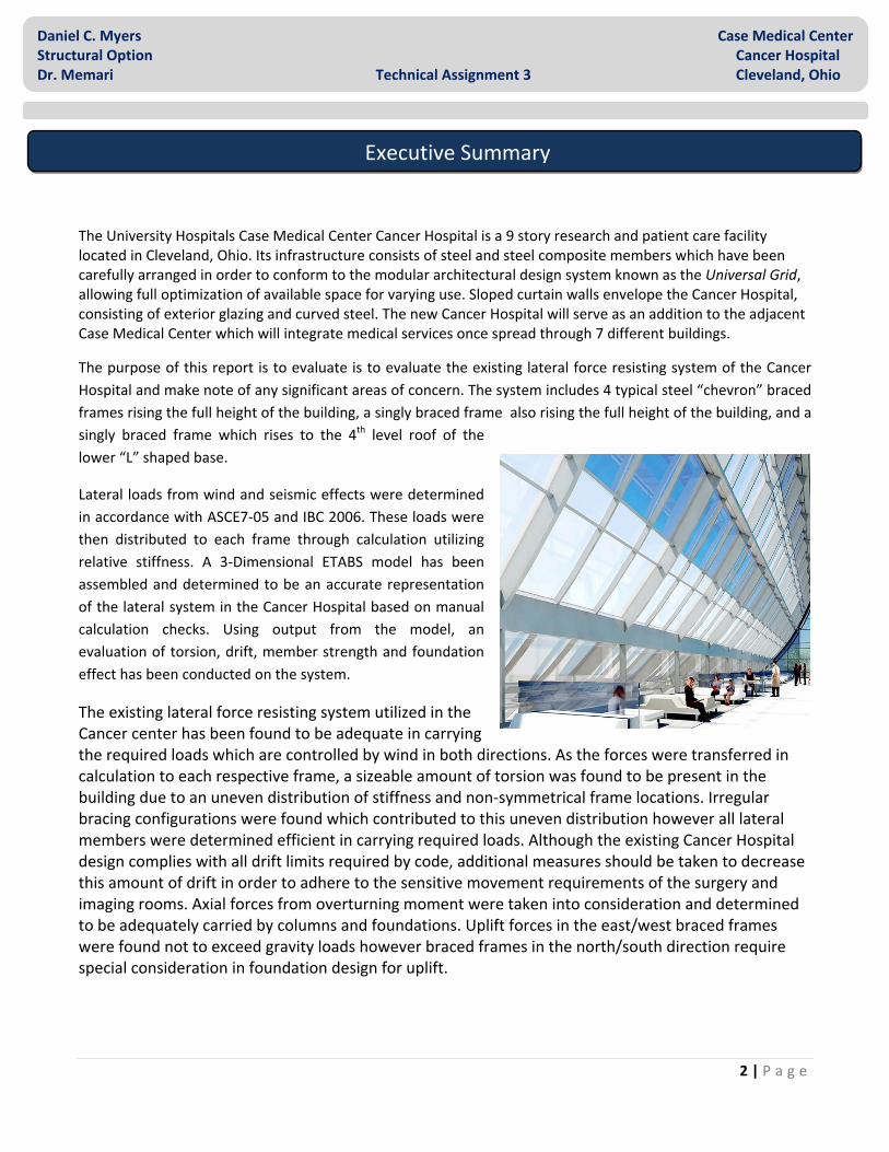
Lateral loads from wind and seismic effects were determined in accordance with ASCE7‐05 and IBC 2006. These loads were then distributed to each frame through calculation utilizing relative stiffness. A 3‐Dimensional ETABS model has been assembled and determined to be an accurate representation of the lateral system in the Cancer Hospital based on manual calculation checks. Using output from the model, an evaluation of torsion, drift, member strength and foundation effect has been conducted on the system.
The existing lateral force resisting system utilized in the Cancer center has been found to be adequate in carrying the required loads which are controlled by wind in both directions. As the forces were transferred in calculation to each respective frame, a sizeable amount of torsion was found to be present in the building due to an uneven distribution of stiffness and non‐symmetrical frame locations. Irregular bracing configurations were found which contributed to this uneven distribution however all lateral members were determined efficient in carrying required loads. Although the existing Cancer Hospital design complies with all drift limits required by code, additional measures should be taken to decrease this amount of drift in order to adhere to the sensitive movement requirements of the surgery and imaging rooms. Axial forces from overturning moment were taken into consideration and determined to be adequately carried by columns and foundations. Uplift forces in the east/west braced frames were found not to exceed gravity loads however braced frames in the north/south direction require special consideration in foundation design for uplift.
Executive Summary

3 | P a g e
Daniel C. Myers Case Medical Center Structural Option Cancer Hospital Dr. Memari Technical Assignment 3 Cleveland, Ohio
Introduction ……………………………………………………………………….……...………………..........… 4
Existing Structural Systems ........................................................................................ 5
Code and Design Requirements ................................................................................ 8
Lateral Loads
Seismic ………………….………………………………................................….……...........…..... 8
Wind ....………………….……………………………...............................…….……................. 12
Controlling Load ……………….…..…………………………...............…………......…....……….. 15
Load Path ……….………………….......................................………………....…….…..…...…. 17
Frame Contribution
Stiffness .............................................................................................................. 19
Rigidity ............................................................................................................... 20
Frame Force ........................................................................................................ 22
ETABS Model ...................................................................................................... 25
Design Checks
Member Strength .............................................................................................. 29
Drift Analysis ....................................................................................................... 31
Overturning Moment ........................................................................................ 33
Summary .................................................................................................................. 34
Conclusion ............................................................................................................... 36
Appendix A ............................................................................................................... 37
Appendix B ............................................................................................................... 46
Appendix D ............................................................................................................... 54
Appendix E ................................................................................................................ 62
Table of Contents
4 | P a g e
Daniel C. Myers Case Medical Center Structural Option Cancer Hospital Dr. Memari Technical Assignment 3 Cleveland, Ohio
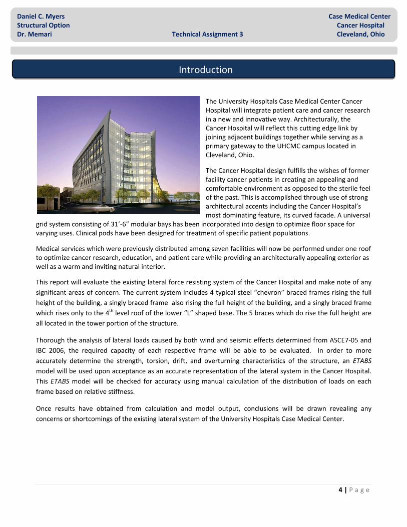
The University Hospitals Case Medical Center Cancer Hospital will integrate patient care and cancer research in a new and innovative way. Architecturally, the Cancer Hospital will reflect this cutting edge link by joining adjacent buildings together while serving as a primary gateway to the UHCMC campus located in Cleveland, Ohio.
The Cancer Hospital design fulfills the wishes of former facility cancer patients in creating an appealing and comfortable environment as opposed to the sterile feel of the past. This is accomplished through use of strong architectural accents including the Cancer Hospital’s most dominating feature, its curved facade. A universal
grid system consisting of 31’‐6” modular bays has been incorporated into design to optimize floor space for varying uses. Clinical pods have been designed for treatment of specific patient populations.
Medical services which were previously distributed among seven facilities will now be performed under one roof to optimize cancer research, education, and patient care while providing an architecturally appealing exterior as well as a warm and inviting natural interior.
This report will evaluate the existing lateral force resisting system of the Cancer Hospital and make note of any significant areas of concern. The current system includes 4 typical steel “chevron” braced frames rising the full height of the building, a singly braced frame also rising the full height of the building, and a singly braced frame which rises only to the 4th level roof of the lower “L” shaped base. The 5 braces which do rise the full height are all located in the tower portion of the structure.
Thorough the analysis of lateral loads caused by both wind and seismic effects determined from ASCE7‐05 and IBC 2006, the required capacity of each respective frame will be able to be evaluated. In order to more accurately determine the strength, torsion, drift, and overturning characteristics of the structure, an ETABS model will be used upon acceptance as an accurate representation of the lateral system in the Cancer Hospital. This ETABS model will be checked for accuracy using manual calculation of the distribution of loads on each frame based on relative stiffness.
Once results have obtained from calculation and model output, conclusions will be drawn revealing any concerns or shortcomings of the existing lateral system of the University Hospitals Case Medical Center.
Introduction

5 | P a g e
Daniel C. Myers Case Medical Center Structural Option Cancer Hospital Dr. Memari Technical Assignment 3 Cleveland, Ohio
Foundation
The Cancer Hospital consists of drilled piers transferring load to caissons for the gravity columns with the combined use of grade beams for the lateral force resisting frames. The drilled gravity piers/caissons range 30” to 60” in diameter depending on location. The drilled piers/caissons receiving lateral load are typically 66” in diameter. Along the south side, 36” thick spread footings, typically 48” by 72”, have been used to carry gravity load along the existing adjacent Case Medical Center Hospital. The grade beams which carry the lateral load to the drilled piers/caissons are typically 24” by 24” and consist of Grade 60, #7 reinforcement bars. All foundations are made from concrete having a compressive strength of 4000psi with the exception of the caissons and spread footings, which have a strength of 3000psi.
The soil on site has been classified as hard shale (see Figure 1). Thus, giving the caissons used in the foundation an end bearing capacity of 50kpf with a skin friction capacity of 10psi below the first 5’ of shale. The typical minimum penetration depth for the gravity piers/caissons is 3’‐0” and for the lateral, 16’‐6”.
Floor System
Being a primarily steel structure, the Cancer Hospital has a fairly typical composite steel beam and girder framing system. The typical composite floor slab is 5‐1/4” thick using 3000psi lightweight composite concrete, an 18 gauge 2” galvanized steel deck, and 3‐1/2” metal studs. This composite floor slab is used on all but the 2nd and 8th floors. The second floor requiring a thicker slab with normal weight concrete due the vibration requirements of the surgery and imaging rooms and the 8th due to the increased load from the mechanical system. The slab used on these floors consists of 6‐1/2” thick 3000psi normal weight concrete, an 18 gauge 2” galvanized steel deck, and 3‐1/2” metal studs. Both decks are reinforced with 6x6 Welded Wire Fabric; W4.5xW4.5 for the first floor, W3.5xW3.5 for the second and eighth floors, and W2.1x2.1 for the remaining floors.
Figure 1
Existing Structural Systems
Figure 2

6 | P a g e
Daniel C. Myers Case Medical Center Structural Option Cancer Hospital Dr. Memari Technical Assignment 3 Cleveland, Ohio
Framing
Bay sizes conform to the universal grid, having a typical size of 31’‐6” by 31’‐6”. Infill beams are typically W16x26 around the interior and W14x22 around the exterior framing into W24x68 girders (see Figure 2). For the larger breaks in the slab, such as the elevator shafts, HSS 8x4x1/4 tubes have been used. On the 4th and roof level, moment connections are utilized in conjunction with cantilevered beams in order to support the curved exterior façade. Smaller breaks used for mechanical, plumbing, etc., consist typically of W10x17. Columns consist of a typical W14 member decreasing in size with elevation and spliced every other floor starting with the second. All steel members conform to ASTM A‐992, Grade 50 unless otherwise noted.
Ground Level At the ground level, a 6” thick slab‐on‐grade is used with Grade 60 #5 reinforcement bars spaced @ 18”oc EW. The slab rests on a 10 mils min. vapor barrier on compacted granular material over a 2000psi mud slab. In the northeastern and southeastern section of the building special research equipment has been placed requiring a 12” thick slab‐on‐grade with Grade 60 #5 reinforcement bars placed @ 12”oc EW. Machine Room A 31’‐0” by 63’‐0” machine room is located on the 8th floor. Framing is similar to the rest of the structure however with shorter spans and larger members to account for the additional weight. Beams range from W21 beams to W40 beams depending on specific equipment.
Roof System
The roof of the Cancer Center is a sloped deck with a 63’‐0’ by 63’‐0” elevator penthouse perched at the southern corner. The roof slopes downward along the east and west sides of the building and allows drainage to the center third. The roof system consists of a 3”x20ga type ‘N’ galvanized steel deck. The roof deck rests typically rests on W14x22 beams framing into W21x44 girders with W18x35 beams being used to support mechanical equipment spaced uniformly across the building’s center. Roof decks lower than the top of the 8th level consist of 1.5”x20ga. type ‘B’ galvanized steel deck (see Figure 3).
Figure 3

7 | P a g e
Daniel C. Myers Case Medical Center Structural Option Cancer Hospital Dr. Memari Technical Assignment 3 Cleveland, Ohio
Lateral System
Lateral forces are resisted by a series of concentrically braced frames located at the center of the building near the main elevator core and along isolated points of the exterior bays (see Figure 4). This system consists of four chevron braces and two diagonal braces, which are used both in the north/south direction as well as the east/ west direction. Each brace typically consists of a 31’‐6” wide W24 beam, a 15’‐0’ tall W14 column, and two HSS8 size diagonal members (see Figure 5). Structural brace members beyond the 8th floor increase in size due to increased lateral loads.
Figure 4
Figure 5

8 | P a g e
Daniel C. Myers Case Medical Center Structural Option Cancer Hospital Dr. Memari Technical Assignment 3 Cleveland, Ohio
Codes
IBC 2006 International Building Code
ASCE‐7‐05 Design Code for Minimum Design Loads
LRFD Specifications for Structural Steel Design – Unified Version, 2005
References
ETABS V9.2.0
Seismic
All tables, figures, and equations used in calculation of seismic loads were done so in accordance with Chapter 12 of ASCE 7‐05. Although the structure falls under design category A allowing simplified procedure, the Equivalent Lateral Force Procedure was utilized in order to gain greater accuracy in the development of results. Due to the complexity and diversity of loads on each floor of the Cancer Center, a Load Key Diagram was obtained from the structural consultant in order to accurately calculate effective story weight to be used in the Equivalent Lateral Force Procedure (see Appendix D).
Code and Design Requirements
Lateral Loads
Figure 6
9 | P a g e
Daniel C. Myers Case Medical Center Structural Option Cancer Hospital Dr. Memari Technical Assignment 3 Cleveland, Ohio
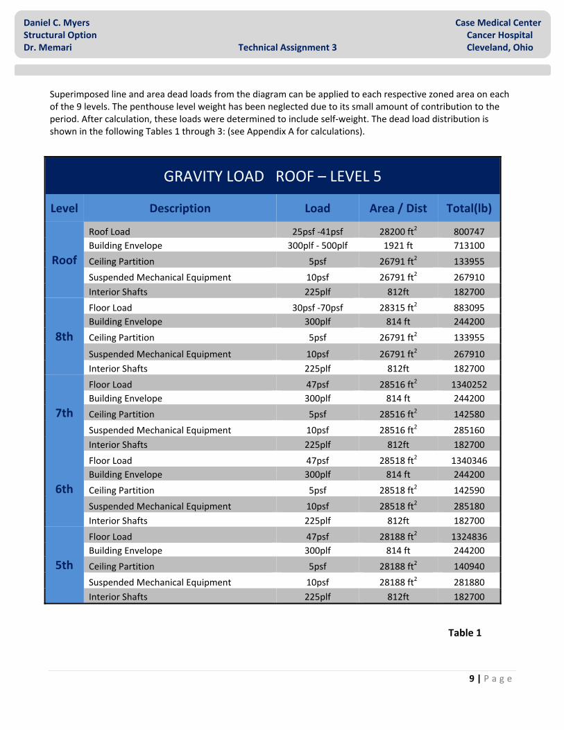
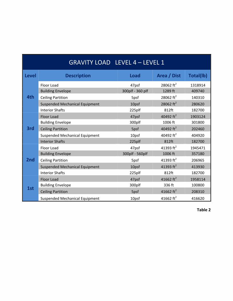
Superimposed line and area dead loads from the diagram can be applied to each respective zoned area on each of the 9 levels. The penthouse level weight has been neglected due to its small amount of contribution to the period. After calculation, these loads were determined to include self‐weight. The dead load distribution is shown in the following Tables 1 through 3: (see Appendix A for calculations).
Table 1
GRAVITY LOAD ROOF – LEVEL 5
Level Description Load Area / Dist Total(lb)
Roof
Roof Load 25psf ‐41psf 28200 ft2 800747 Building Envelope 300plf ‐ 500plf 1921 ft 713100
Ceiling Partition 5psf 26791 ft2 133955
Suspended Mechanical Equipment 10psf 26791 ft2 267910
Interior Shafts 225plf 812ft 182700
8th
Floor Load 30psf ‐70psf 28315 ft2 883095 Building Envelope 300plf 814 ft 244200
Ceiling Partition 5psf 26791 ft2 133955
Suspended Mechanical Equipment 10psf 26791 ft2 267910 Interior Shafts 225plf 812ft 182700
7th
Floor Load 47psf 28516 ft2 1340252 Building Envelope 300plf 814 ft 244200
Ceiling Partition 5psf 28516 ft2 142580
Suspended Mechanical Equipment 10psf 28516 ft2 285160 Interior Shafts 225plf 812ft 182700
6th
Floor Load 47psf 28518 ft2 1340346 Building Envelope 300plf 814 ft 244200
Ceiling Partition 5psf 28518 ft2 142590
Suspended Mechanical Equipment 10psf 28518 ft2 285180 Interior Shafts 225plf 812ft 182700
5th
Floor Load 47psf 28188 ft2 1324836 Building Envelope 300plf 814 ft 244200
Ceiling Partition 5psf 28188 ft2 140940
Suspended Mechanical Equipment 10psf 28188 ft2 281880 Interior Shafts 225plf 812ft 182700
GRAVITY LOAD LEVEL 4 – LEVEL 1
Level Description Load Area / Dist Total(lb)
4th
Floor Load 47psf 28062 ft2 1318914 Building Envelope 300plf ‐ 360 plf 1289 ft 409740
Ceiling Partition 5psf 28062 ft2 140310
Suspended Mechanical Equipment 10psf 28062 ft2 280620
Interior Shafts 225plf 812ft 182700
3rd
Floor Load 47psf 40492 ft2 1903124 Building Envelope 300plf 1006 ft 301800
Ceiling Partition 5psf 40492 ft2 202460
Suspended Mechanical Equipment 10psf 40492 ft2 404920
Interior Shafts 225plf 812ft 182700
2nd
Floor Load 47psf 41393 ft2 1945471 Building Envelope 300plf ‐ 560plf 1006 ft 357180
Ceiling Partition 5psf 41393 ft2 206965
Suspended Mechanical Equipment 10psf 41393 ft2 413930
Interior Shafts 225plf 812ft 182700
1st
Floor Load 47psf 41662 ft2 1958114 Building Envelope 300plf 336 ft 100800
Ceiling Partition 5psf 41662 ft2 208310
Suspended Mechanical Equipment 10psf 41662 ft2 416620
Table 2

11 | P a g e
Daniel C. Myers Case Medical Center Structural Option Cancer Hospital Dr. Memari Technical Assignment 3 Cleveland, Ohio
Table 3 Table 4
GRAVITY LOAD
Level Load(lb)
Roof 2098412 8 1711860
7 2194892
6 2195016 5 2174556
3 2995004 2 3106246
1 2683844
Total Wt. 19159830
The maximum lateral story force was determined to be 41.57k at the roof level (see Table 4). This value is reasonable due to the low amount of seismic activity in Cleveland, Ohio. Base shear was found to be 214.9 kips, placing it within 1% error when compared to value of 213.6k calculated by the consultant engineer (see Figure 5). For further calculation details see Appendix A.
SEISMIC FACTORS Ss 19.20% Sds 0.1536 S1 5.10% Sd1 0.058
Site Class C Occupancy Cat. IV Fa 1.2 Seismic Des. Cat. A
Fv 1.7 Cs 0.01
Sms 0.2304 Ta 1.31 Sm1 0.0867 V 214.9k
R 7 I 1.5
SEISMIC FORCES
Level wx hi Σwihi Cvx Story Force(k)
Roof 2098412 132 1431970472 0.19 41.57 8 1711860 117 1431970472 0.14 30.06 7 2194892 102 1431970472 0.16 33.60 6 2195016 87 1431970472 0.13 28.66 5 2174556 72 1431970472 0.11 23.50 4 2332284 57 1431970472 0.09 19.95 3 2995004 42 1431970472 0.09 18.88 2 3106246 28 1431970472 0.06 13.05 1 2683844 14 1431970472 0.03 5.64
Table 5
12 | P a g e
Daniel C. Myers Case Medical Center Structural Option Cancer Hospital Dr. Memari Technical Assignment 3 Cleveland, Ohio
Wind
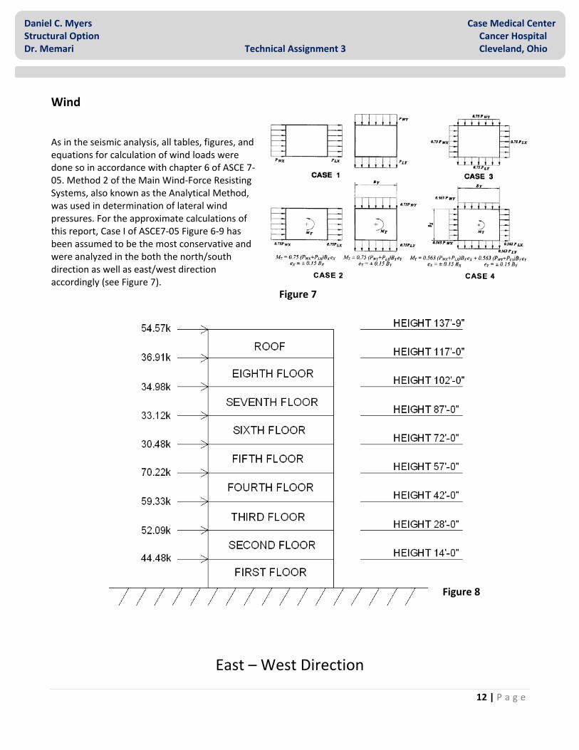
As in the seismic analysis, all tables, figures, and equations for calculation of wind loads were done so in accordance with chapter 6 of ASCE 7‐05. Method 2 of the Main Wind‐Force Resisting Systems, also known as the Analytical Method, was used in determination of lateral wind pressures. For the approximate calculations of this report, Case I of ASCE7‐05 Figure 6‐9 has been assumed to be the most conservative and were analyzed in the both the north/south direction as well as east/west direction accordingly (see Figure 7).
East – West Direction
Figure 7
Figure 8

13 | P a g e
Daniel C. Myers Case Medical Center Structural Option Cancer Hospital Dr. Memari Technical Assignment 3 Cleveland, Ohio
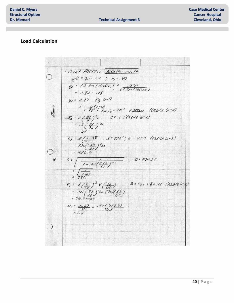
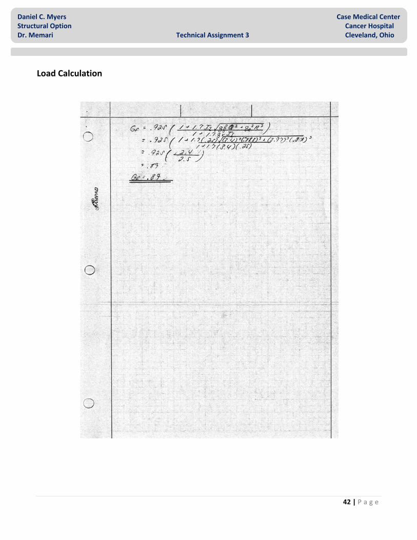
Different gust factors resulted due to flexibility (see Table 6). A conservative approach was taken in east/west direction in order to account for the vertical “L” shape caused by the lower 4 story, southern wing of the Cancer Hospital. Since the code is unclear about applying wind pressures to non‐uniform shapes, a rectangular shape was used in calculation. This will cause the lateral forces to be larger than in actuality (see Appendix D for North Elevation).
North – South Direction
For this analysis internal pressures and roof top uplift pressures have been ignored, however, overturning moment has been determined. The maximum point load was calculated to be 191k in the north/south direction and 54.57K in the east /west direction at the roof level (see Figures 8 – 9). The wind pressure and story shear for each are included in the following Tables 7 through 9: (see Appendix A for calculations).
Wind Factors
V 90mph n 0.4 Kd 0.85 G .89/.84 I 1.15 qz 20.27
Exp. Cat. B qi 22.7 Kzt 1 qh 22.7
Kh 1.2 Cp 0.8
Table 6
Figure 9

14 | P a g e
Daniel C. Myers Case Medical Center Structural Option Cancer Hospital Dr. Memari Technical Assignment 3 Cleveland, Ohio
Table 7
WIND ANALYSIS
Windward
Story Tributary Height (ft)
Kz qz (psf)
Penthouse 16.33 1.12 22.7 High Roof 7.17 1.08 21.9 Low Roof 13.58 1.06 21.5
8 15 1.03 20.9 7 15 0.99 20.1 6 15 0.95 19.3 5 15 0.89 18.0 4 15 0.84 17.0 3 14 0.77 15.6 2 14 0.68 13.8 1 14 0.57 11.6
Leeward 154.1 1.12 22.7
Side 154.1 1.12 22.7
Table 8
NORTH ‐ SOUTH DIRECTION
Story Tributary Height (ft)
External Pressure qGCp (psf)
Forces (k) Story Shear
(k) Overturn
Moment (ft‐k)
Roof 20.75 22.63 191.16 95.50 95.50 8 15 21.04 129.23 224.50 6363.25 7 15 20.27 122.19 346.50 12078.25 6 15 19.14 116.84 462.50 19578.25 5 15 17.68 106.70 568.50 28743.25 4 15 16.28 99.34 667.50 39445.75 3 14 14.29 84.26 751.50 51097.25 2 14 12.73 74.98 825.50 63473.25 1 14 10.70 63.56 888.50 76808.25

15 | P a g e
Daniel C. Myers Case Medical Center Structural Option Cancer Hospital Dr. Memari Technical Assignment 3 Cleveland, Ohio
Table 9
EAST ‐ WEST DIRECTION
Story Tributary Height (ft)
External Pressure qGCp (psf)
Forces (k) Story Shear
(k) Overturn
Moment (ft‐k) Roof 20.75 21.36 54.57 27.29 27.29 8 15 19.86 36.91 64.20 1818.43 7 15 19.13 34.98 99.18 3452.98 6 15 18.06 33.12 132.30 5598.28 5 15 16.69 30.48 162.78 8220.58 4 15 15.37 70.22 233.00 11598.13 3 14 13.49 59.33 292.33 15787.50 2 14 12.01 52.09 344.42 20626.67 1 14 10.10 44.48 388.90 26141.83
Controlling Load
Wind loads were compared to seismic loads in both the north/south and east/west directions. Wind was found to control over seismic in both orientations (see Table 10 and Charts 1 ‐ 2). This is as expected due to the low seismic region in which the Cancer Hospital is located. The north/south wind load is significantly larger than the east/west direction due to the increase in pressure area of on the north and south face. A difference in wind force from levels 1‐4 to levels 5‐R can be noticed in the east/west direction. This is caused by the decrease in the pressure zone size as the transition is made from the lower “L” shape to the upper tower levels.
Table 10
LATERAL LOADS
Story Wind N/S (k)
Wind E/W (k)
Seismic N/S (k)
Seismic E/W (k)
Roof 191.00 54.57 41.57 41.57
8 129.00 36.91 30.05 30.05
7 122.00 34.98 33.06 33.06
6 116.00 33.12 28.66 28.66
5 106.00 30.48 23.5 23.50
4 99.00 70.22 19.95 19.95
3 84.00 59.33 18.88 18.88
2 74.00 52.09 13.05 13.05
1 63.00 44.48 5.6 5.60
Ground 0.00 0.00 0.00 0.00

16 | P a g e
Daniel C. Myers Case Medical Center Structural Option Cancer Hospital Dr. Memari Technical Assignment 3 Cleveland, Ohio
020406080
100120140160180200
Roof 8 7 6 5 4 3 2 1
Lateral Load
(kips)
Story Level
Contolling Load in North ‐ South
Wind
Seismic
0
10
20
30
40
50
60
70
80
Roof 8 7 6 5 4 3 2 1
Lateral Load
(kips)
Story Level
Contolling Load in East ‐West
Wind
Seismic
Chart 1
Chart 2
17 | P a g e
Daniel C. Myers Case Medical Center Structural Option Cancer Hospital Dr. Memari Technical Assignment 3 Cleveland, Ohio
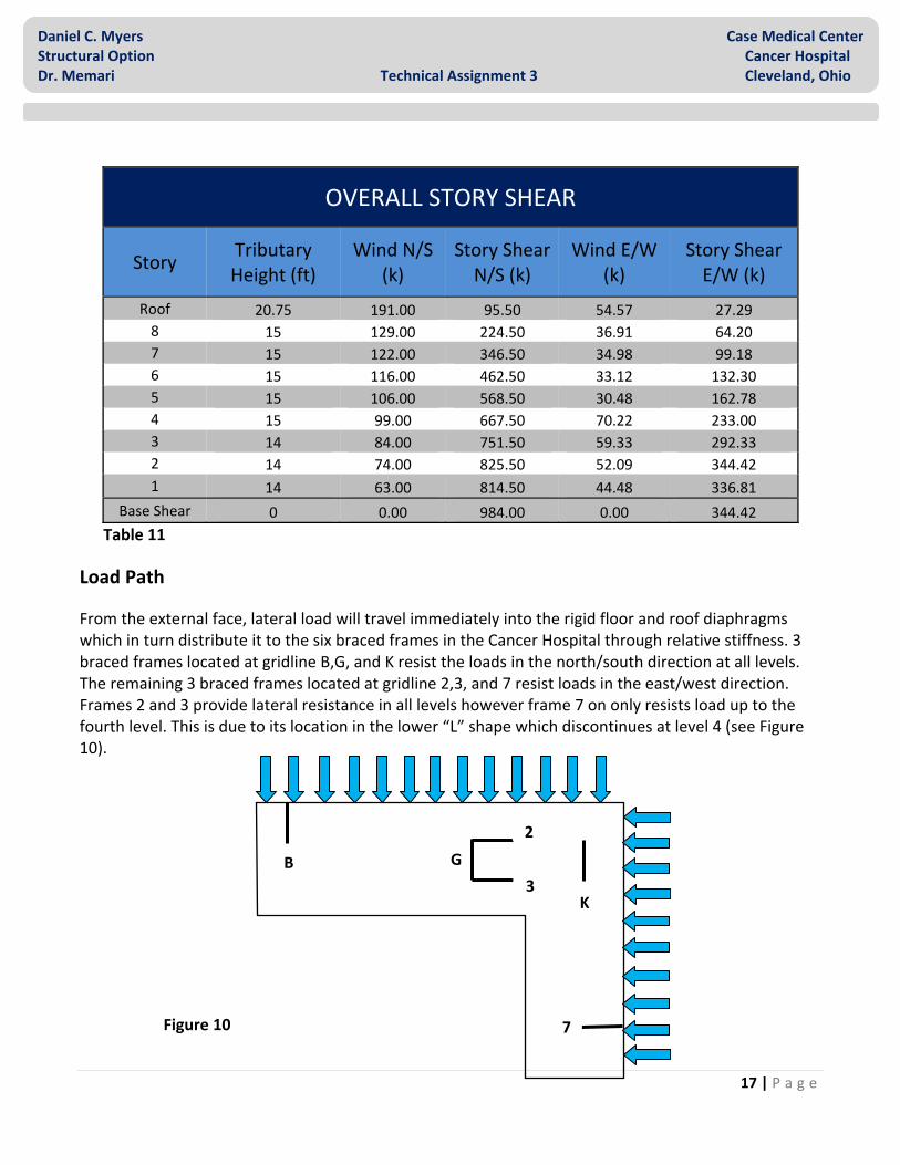
Table 11
Load Path
From the external face, lateral load will travel immediately into the rigid floor and roof diaphragms which in turn distribute it to the six braced frames in the Cancer Hospital through relative stiffness. 3 braced frames located at gridline B,G, and K resist the loads in the north/south direction at all levels. The remaining 3 braced frames located at gridline 2,3, and 7 resist loads in the east/west direction. Frames 2 and 3 provide lateral resistance in all levels however frame 7 on only resists load up to the fourth level. This is due to its location in the lower “L” shape which discontinues at level 4 (see Figure 10).
OVERALL STORY SHEAR
Story Tributary Height (ft)
Wind N/S (k)
Story Shear N/S (k)
Wind E/W (k)
Story Shear E/W (k)
Roof 20.75 191.00 95.50 54.57 27.29 8 15 129.00 224.50 36.91 64.20 7 15 122.00 346.50 34.98 99.18 6 15 116.00 462.50 33.12 132.30 5 15 106.00 568.50 30.48 162.78 4 15 99.00 667.50 70.22 233.00 3 14 84.00 751.50 59.33 292.33 2 14 74.00 825.50 52.09 344.42 1 14 63.00 814.50 44.48 336.81
Base Shear 0 0.00 984.00 0.00 344.42
B G
K
2
3
7Figure 10

18 | P a g e
Daniel C. Myers Case Medical Center Structural Option Cancer Hospital Dr. Memari Technical Assignment 3 Cleveland, Ohio
Once the lateral load has reached the frame at each story, it is then distributed to the members. The resulting horizontal force is transferred as shear and is primarily taken by either a “chevron” or single brace depending on the frame. In the case of the single brace, this wind load is the only load calculated in the strength design however, in the case of the “chevron” braces, the wind load is taken into account in conjunction with the gravity and live loads from the center point of the above beam (see Figure 11). On frame B and 7, the braces have been stepped back 4’‐0” from the beam and column corner joint forcing a moment into the beam and a moment connection. This step back has presumably been constructed due to the location of these frames at the perimeter of the structure. The effect of this special connection has been assumed to be negligible due to the small amount of eccentricity that it endues on the load path. The remaining amount of shear which has not been absorbed by the brace is transferred into the columns. This remaining shear is minimal and will not be taken into account for the approximate methods of calculation in this report. In addition to the shear force in the braces, the overall over‐turning of the frame causes a tensile force in the columns of the receiving side and a compressive force in the columns of the opposite side (see Figure 11). The beam has been assumed to take no axial load since it contributes minimally in comparison to the diaphragm.
Figure 11 Figure 11
19 | P a g e
Daniel C. Myers Case Medical Center Structural Option Cancer Hospital Dr. Memari Technical Assignment 3 Cleveland, Ohio
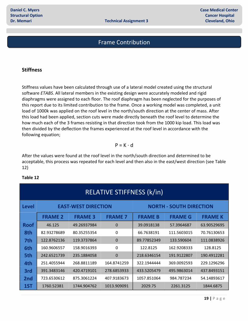
Stiffness
Stiffness values have been calculated through use of a lateral model created using the structural software ETABS. All lateral members in the existing design were accurately modeled and rigid diaphragms were assigned to each floor. The roof diaphragm has been neglected for the purposes of this report due to its limited contribution to the frame. Once a working model was completed, a unit load of 1000k was applied on the roof level in the north/south direction at the center of mass. After this load had been applied, section cuts were made directly beneath the roof level to determine the how much each of the 3 frames resisting in that direction took from the 1000 kip load. This load was then divided by the deflection the frames experienced at the roof level in accordance with the following equation;
P = K ∙ d
After the values were found at the roof level in the north/south direction and determined to be acceptable, this process was repeated for each level and then also in the east/west direction (see Table 12)
Table 12
RELATIVE STIFFNESS (k/in)
Level EAST‐WEST DIRECTION NORTH ‐ SOUTH DIRECTION
FRAME 2 FRAME 3 FRAME 7 FRAME B FRAME G FRAME K
Roof 46.125 49.26937984 0 39.0918138 57.3964687 63.90529695
8th 82.93278689 80.35255354 0 66.7638191 111.5603015 70.76130653
7th 122.8762136 119.3737864 0 89.77852349 133.590604 111.0838926
6th 160.9606557 158.9016393 0 122.8125 162.9208333 128.8125
5th 242.6521739 235.1884058 0 218.6346154 191.9122807 190.4912281
4th 251.4055944 268.8811189 164.8741259 322.1944444 369.0092593 229.1296296
3rd 391.3483146 420.4719101 278.6853933 433.5205479 495.9863014 437.8493151
2nd 723.6530612 875.3061224 407.9183673 1057.851064 984.787234 54.14893617
1ST 1760.52381 1744.904762 1013.909091 2029.75 2261.3125 1844.6875
Frame Contribution

20 | P a g e
Daniel C. Myers Case Medical Center Structural Option Cancer Hospital Dr. Memari Technical Assignment 3 Cleveland, Ohio
Rigidity
Of the 6 braced frames in the Cancer Hospital, only the frame located at gridline 7 does not rise to the full height of the structure. This will cause a different rigidity in levels 1 through 4 located in the lower “L” shape as opposed to levels 5 through 9 located in the upper tower. In order perform calculations, a theoretical square footprint has been assumed and a point in the extreme bottom left of this footprint has been selected. This point will serve as the zero point in which the distance to the frames will be based on (see Figure 12). Once these distances have been calculated in both the north/south as well as the east/west direction, the center of rigidity was calculated for each level using the following equations (see Table 13 for calculated values);
x = ΣKixi/ΣKi
y = ΣKiyi/ΣKi
.
200.9’
170.25’
43.41’
24.25’
181.75’
276.25’
B G
K
2
3
7
CR
Figure 12

21 | P a g e
Daniel C. Myers Case Medical Center Structural Option Cancer Hospital Dr. Memari Technical Assignment 3 Cleveland, Ohio
In addition to the center of rigidity, the center of mass was also calculated for future use. In order to find this figure, the centroids of both legs in the “L” shape bottoms were combined. For this approximate calculation, mass has been assumed to be uniformly distributed throughout the structure (see Table 14).
RIGIDITY
Level NORTH ‐ SOUTH EAST ‐ WEST
Roof 105.5957495 151.547828
8th 101.7555933 144.959525
7th 101.8614401 146.3818148
6th 102.4930708 142.1965655
5th 101.7699418 133.8245927
4th 146.6987028 133.4760194
3rd 149.3782366 139.8499726
2nd 144.1657082 107.0494225
1ST 141.5963084 137.5052144
Table 13
CENTER OF MASS
Level NORTH ‐ SOUTH (IN) EAST ‐ WEST (IN)
Roof 154.6 185.1
8th 154.6 185.1
7th 154.6 185.1
6th 154.6 185.1
5th 154.6 185.1
4th 186.2 152.2
3rd 186.2 152.2
2nd 186.2 152.2
1ST 186.2 152.2
Table 14

22 | P a g e
Daniel C. Myers Case Medical Center Structural Option Cancer Hospital Dr. Memari Technical Assignment 3 Cleveland, Ohio
Frame Force
Direct Shear
Once relative stiffness values had been found, the external forces were then distributed as direct shear to each frame. Calculations were performed in a spreadsheet using the following equation where ΣKi is the sum of the relative stiffness of each in‐plane frame;
Fdirect shear = Fi ∙ Ki / ΣKi
Torsion
In addition to the direct shear forces, each frame will take a torsional force at every level caused by the non‐symmetrical nature of both the building and the location of the braced frames. This torsion was found using a spreadsheet utilizing the following equation;
Ftorsion = Mi ∙ Kidi / ΣKidi
In this equation, the moment is caused by the force at the center of pressure multiplied by the eccentricity of the center of rigidity. In the case of seismic lateral loads, the eccentricity is from the center of mass to the center of rigidity. Each distance multiplied by the relative stiffness in the previous equation is measured from the location of the frame to the location of the center of mass.
Though analysis of obtained data, the Cancer Center appears to have significant torsional forces concentrated primarily at the braces closest to the outskirts of the building in both directions. The frames which are most affected include frame B, K, and 7. This torsional force is most likely due to the “L” shaped base, in addition to the off‐symmetrical location of the braced frames in the tower (see Figure 13). Investigation will be conducted in a future report to evaluate the effect of using a different structural configuration or material to reduce this torsional value.
Figure 13

23 | P a g e
Daniel C. Myers Case Medical Center Structural Option Cancer Hospital Dr. Memari Technical Assignment 3 Cleveland, Ohio
After both direct shear and torsion for each frame at every level were found, the forces were then added together to determine the total force at each level (see Tables 15 ‐ 18). Detailed spreadsheets used in calculating direct shear, torsion, and total force are provided in Appendix B.
TOTAL WIND FORCE NORTH – SOUTH
Level EAST – WEST DIRECTION NORTH – SOUTH DIRECTION
FRAME 2 FRAME 3 FRAME 7 FRAME B FRAME G FRAME K
Roof 1.240278687 0.449942102 0 43.90534703 69.55184905 80.84165279
8th 1.115356341 0.367014903 0 32.39268463 59.07335952 39.35386719
7th 1.073500892 0.35419318 0 30.89918768 49.82558346 43.35283322
6th 1.073475697 0.35991297 0 32.29008863 46.41741085 38.40071999
5th 2.546582094 0.838274081 0 33.18909731 35.77230379 39.46593351
4th 1.539867382 0.559326408 ‐2.324370176 29.97269392 41.77878042 28.72068046
3rd 1.249788276 0.456043848 ‐2.048479354 23.23058438 31.79960367 30.84095022
2nd 1.654922722 0.679835622 ‐2.147162838 31.29110835 36.55193919 2.255153606
1ST 0.984812681 0.331497374 ‐1.305434699 18.05023047 24.27955935 21.84951896
Table 15
TOTAL WIND FORCE EAST – WEST
Level EAST – WEST DIRECTION NORTH – SOUTH DIRECTION
FRAME 2 FRAME 3 FRAME 7 FRAME B FRAME G FRAME K
Roof 25.2915617 27.78602982 0 2.226500091 ‐1.210760669 ‐4.34393277
8th 17.76544566 17.84090249 0 1.901379267 ‐1.176720982 ‐2.405097947
7th 16.79894642 16.92653353 0 1.661416972 ‐0.915626458 ‐2.453390145
6th 15.72352767 16.13863801 0 1.735045089 ‐0.852473823 ‐2.171878593
5th 14.63927911 14.72513341 0 1.815632604 ‐0.590266387 ‐1.887962545
4th 23.05226208 26.57163859 20.9948538 8.367937613 ‐3.549554801 ‐7.102168658
3rd 19.08961658 22.07367999 18.77487203 5.872138304 ‐2.488241371 ‐7.078163755
2nd 15.8654339 21.52010621 14.37170995 10.25719327 ‐3.536573248 ‐0.626618601
1ST 15.59301161 16.59091608 12.28118757 4.814865074 ‐1.9867279 ‐5.222443121
Table 16

24 | P a g e
Daniel C. Myers Case Medical Center Structural Option Cancer Hospital Dr. Memari Technical Assignment 3 Cleveland, Ohio
TOTAL SEISMIC FORCE NORTH – SOUTH
Level EAST – WEST DIRECTION NORTH – SOUTH DIRECTION
FRAME 2 FRAME 3 FRAME 7 FRAME B FRAME G FRAME K
Roof 20.36932607 21.56785884 0 ‐0.549344044 0.298730804 1.071777902
8th 15.5212867 14.87275517 0 ‐0.501322498 0.31025725 0.634134247
7th 17.05829206 16.38646407 0 ‐0.508500929 0.28024085 0.750895885
6th 14.68712219 14.32656251 0 ‐0.486185135 0.238875694 0.608592303
5th 12.14270545 11.63532225 0 ‐0.453392766 0.147399044 0.471454719
4th 8.268199527 8.173406641 3.369772703 ‐2.922586248 1.239717661 2.480503729
3rd 7.637410594 7.594189693 3.412078417 ‐2.297061468 0.973349584 2.768834177
2nd 5.604178091 6.060909504 1.486765488 ‐3.159787712 1.088180124 0.193033484
1ST 2.450163227 2.252580484 0.90022316 ‐0.745150204 0.307466705 0.808227125
TOTAL SEISMIC FORCE EAST – WEST
Level EAST – WEST DIRECTION NORTH – SOUTH DIRECTION
FRAME 2 FRAME 3 FRAME 7 FRAME B FRAME G FRAME K
Roof 0.269439127 0.09774578 0 9.582275347 15.17445845 17.63443087
8th 0.2588618 0.085180077 0 7.553154181 13.76904165 9.170873172
7th 0.289302907 0.09545322 0 8.365923304 13.48540003 11.73131247
6th 0.264877166 0.088807532 0 8.004567798 11.50255442 9.514160646
5th 0.209172956 0.068854748 0 8.095005838 7.650980622 7.919474537
4th 0.947959779 0.344327664 ‐1.430908573 4.061599736 9.238705045 7.447330362
3rd 0.861969864 0.314530118 ‐1.412821279 3.688846343 7.821763782 8.814512167
2nd 0.898523556 0.369109876 ‐1.165780349 3.424073616 7.217306244 0.530046036
1ST 0.26866362 0.090434746 ‐0.356131495 1.107369863 2.371330128 2.491843635
Table 17
Table 18

25 | P a g e
Daniel C. Myers Case Medical Center Structural Option Cancer Hospital Dr. Memari Technical Assignment 3 Cleveland, Ohio
ETABS Model
As previously stated, an ETABS model has been constructed using the existing design of the Cancer Hospital. Even though the sub‐ground level is actually below the surface and not susceptible to direct lateral loads, the lateral members have been modeled in these areas to increase consistency with the existing design. The diaphragms between braces have been modeled as rigid in order to follow the method of stiffness calculation described previously (see Figure 14 ‐ 15).
Figure 14

26 | P a g e
Daniel C. Myers Case Medical Center Structural Option Cancer Hospital Dr. Memari Technical Assignment 3 Cleveland, Ohio
Upon completion of the modeling of all significant lateral members, un‐factored wind and seismic loads previously calculated were applied in the proper orientation. Initially, the model produced reasonable values for period:
Mode 1 (x): 2.343sec
Mode 2 (y): 1.978sec
Mode 3 (z): 1.610sec
7 3
3
4
5
6
7
8
PENT
ROOF
2K G B
GR
1
2
SUB GR
Figure 15

27 | P a g e
Daniel C. Myers Case Medical Center Structural Option Cancer Hospital Dr. Memari Technical Assignment 3 Cleveland, Ohio
Further investigation was then performed by selecting a representative frame from both the north/south direction and the east/west direction. The frames selected include frame K for analysis in the north/south direction and frame 2 for analysis in the east/west direction. Since wind controls in both directions, seismic loads were not considered. Using the shear cut command in ETABS, values for shear were obtained and compared to results of the manual load calculation using spreadsheets (see tables 19 ‐ 20). Any additional ETABS data is available upon request.
NORTH ‐ SOUTH DIRECTION USING FRAME K
Story Tributary Height (ft)
Forces (k) Frame Shear
(k) ETABS Frame Shear (k)
% Error
Roof 20.75 80.84 40.42 47.39 17.24% 8 15 39.35 79.77 71.91 9.86% 7 15 43.35 123.13 110.74 10.06% 6 15 38.40 161.53 139.34 13.74% 5 15 39.47 200.99 193.24 3.86% 4 15 28.72 229.71 181.00 21.21% 3 14 30.84 260.56 245.81 5.66% 2 14 2.26 262.81 38.94 85.18% 1 14 21.85 284.66 275.21 3.32%
EAST ‐ WEST DIRECTION USING FRAME 2
Story Tributary Height (ft)
Forces (k) Frame Shear
(k) ETABS Frame Shear (k)
% Error
Roof 20.75 25.29 12.65 26.29 107.91% 8 15 17.76 30.41 48.88 60.76% 7 15 16.79 47.20 65.33 38.43% 6 15 15.72 62.92 80.36 27.73% 5 15 14.63 77.55 98.41 26.91% 4 15 23.05 100.60 93.34 7.21% 3 14 19.05 119.65 111.36 6.92% 2 14 15.86 135.51 131.49 2.96% 1 14 15.59 151.10 152.01 0.61%
Table 19
Table 20

28 | P a g e
Daniel C. Myers Case Medical Center Structural Option Cancer Hospital Dr. Memari Technical Assignment 3 Cleveland, Ohio
Upon observation of the resulting error between manual calculation and the ETABS model, the percentage is well underneath the acceptable limit with the exception of two isolated points. The first area of error is on the 2nd and 4th level of frame K (see figure 16). Immediately, it is seen that both of these areas in the frame have a sizeable decrease in stiffness due to the 4th level having a single brace and the 2nd level having no brace at all. This large decrease in stiffness creates a shear reversal in the modeled frame causing the results from ETABS to be varied from the manual calculation. These special locations seem ineffective and future investigation will be conducted in order to find a more efficient approach. The second area of error can be seen in frame 2 from the 5th level to the Roof. In this area the ETABS model has taken a more conservative approach analyzing the lateral loads by creating a pressure zone that is more balanced with the increased size of the zone in the lower “L” shape. In the manual calculations, a less conservative approximation was made based strictly on area.
The center of rigidity from previous manual calculation was also compared to the value used in the ETABS model (see Table 21). Results yielded a sizeable difference in the north/south direction above level 4. This variation has been found to be caused by the consideration of the out‐of‐plane contribution of members acting in the opposite direction in the model. This consideration provides a more accurate result when compared to the manual calculation.
Upon comparison of results and evaluation of areas of concern, the ETABS model has been accepted as an accurate representation of the existing structural system in the Cancer Hospital. The model will be used to obtain values for deflection and member forces used in strength checks.
RIGIDITY COMPARISONLevel NORTH – SOUTH DIRECTION (in) EAST – WEST DIRECTION (in) Hand Calc Etabs %Error Hand Calc Etabs %Error
Roof 105.5957495 155.37425 32.04% 151.547828 174.92875 13.37%
8th 101.7555933 150.3958333 32.34% 144.959525 171.2143333 13.37%
7th 101.8614401 149.1854167 31.72% 146.3818148 168.1620833 13.37%
6th 102.4930708 146.8034167 30.18% 142.1965655 164.4718333 13.37%
5th 101.7699418 143.0035 28.83% 133.8245927 158.8278333 13.37%
4th 146.6987028 138.6399167 5.81% 133.4760194 152.2090833 13.37%
3rd 149.3782366 133.9120833 11.55% 139.8499726 152.5019167 13.37%
2nd 144.1657082 125.7456667 14.65% 107.0494225 154.4185833 13.37%
1ST 141.5963084 158.651 10.75% 137.5052144 154.0863333 13.37%
Table 21
Figure 16

29 | P a g e
Daniel C. Myers Case Medical Center Structural Option Cancer Hospital Dr. Memari Technical Assignment 3 Cleveland, Ohio
Member Strength
Critical members in the lateral system of the existing Cancer Hospital design have been checked to meet strength requirements. As mention previously, the ETABS model has been proven to be an accurate representation of the lateral system utilized in the Cancer Hospital and required service loads have been determined based on program output. Of the lateral system, Frame K is exposed to the highest amount of direct shear, torsion, and also has the most irregularities. For these reasons, Frame K has been chosen for member strength spot checks. Both the “chevron” brace configuration and the single brace configuration have been analyzed in addition to the columns at the base (see Figure 17). Loads on members were determined upon finding the controlling load combination in accordance with ASCE7‐05. See appendix C for detailed calculations.
Applicable load combinations considered include:
1.4D
1.2D + 1.6 L
1.2D + 1.6W+1.0L
.9D + 1.6
Design Checks
Figure 17

30 | P a g e
Daniel C. Myers Case Medical Center Structural Option Cancer Hospital Dr. Memari Technical Assignment 3 Cleveland, Ohio
Chevron Brace @ 6th Level
The chevron brace on the 6th level has been checked for strength (see Figure 18). Not only has lateral loading been considered, but also the dead and live load contribution from the beam on the 7th floor above. The 1.2D + 1.6W +1.0L load combination controls yielding an axial load of 152.3k. Using the AISC Steel Manual as a design aid, the HSS6x6x.5 has been found to have an allowable axial force of 159.92k, making this member adequate to carry the load.
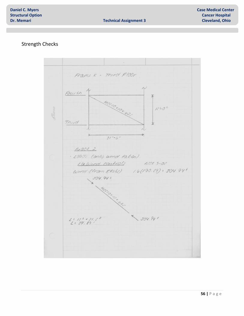
Single Brace @ 3th Level
The single brace on the 3rd level has been analyzed for strength (see Figure 19). This brace is susceptible to lateral loading only. The 1.2D + 1.6W +1.0L load combination also controls in this frame, producing a required axial load of 304.94k. With the use of the AISC Steel Manual for design, the HSS10x10x.625 member was found to have an allowable axial force of 388.58k thus making it acceptable to carry the required load.
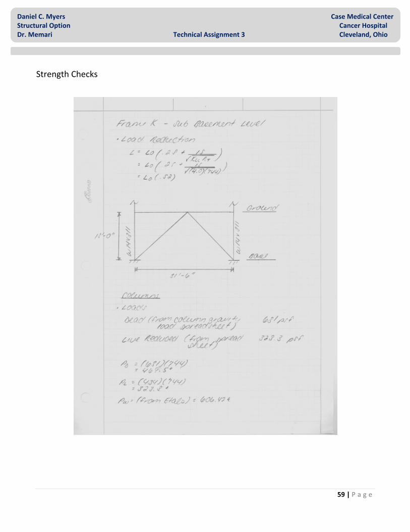
Columns @ Base
The columns at the base level have also been chosen for a strength check (see Figure 20). In addition to the dead and live load from the floors above, these two members are exposed to an axial load at the receiving side of the lateral load, and a compressive load at the opposite side, due to overturning. Both members have been checked to handle the combination of the lateral compressive load in addition to the gravity and live loads of the stories above. The controlling load combination was determined to be 1.2D + 1.6W + 1.0L, yielding a required load of 1856.9k. With the use of the AISC Steel Manual, the W14x311 columns were found to have a maximum axial load capacity of 1846.3k. Although this strength is less than what is required, a conservative approach was taken in determining the loads from the floors above. This capacity, being within 5%, has been determined to be acceptable to carry the axial load (see Table 22).
Figure 18
Figure 19
Figure 20

31 | P a g e
Daniel C. Myers Case Medical Center Structural Option Cancer Hospital Dr. Memari Technical Assignment 3 Cleveland, Ohio
COLUMN LOAD TAKE DOWN
Level Dead Live Reduction Area
Pent 40 psf 30 psf 15.6 psf 744 ft2
Roof 56 psf 100 psf 52 psf 744 ft2
8th 45 psf 150 psf 78 psf 744 ft2
7th 62 psf 60 psf 32 psf 744 ft2
6th 62 psf 60 plf 32 psf 744 ft2
5th 62 psf 60 psf 32 psf 744 ft2
4th 62 psf 60 plf 32 psf 744 ft2
3rd 62 psf 60 psf 32 psf 744 ft2
2nd 62 psf 125 psf 65 psf 744 ft2
1st 62 psf 60 psf 32 psf 744 ft2
Ground 56 psf 100 psf 52 psf 744 ft2
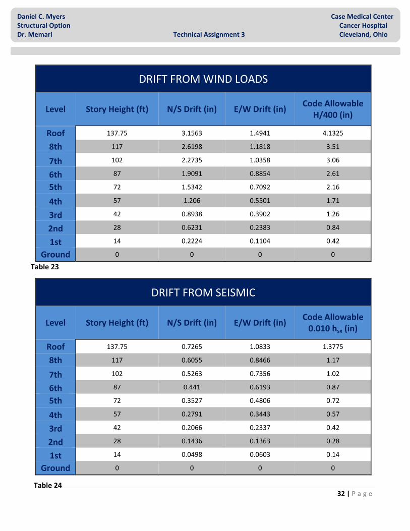
Drift Analysis
The Cancer Hospital has been checked for both story and overall drift from not only wind lateral loads, but also seismic in accordance with ASCE7‐05 and IBC 2006. Drift results have been found using program output from the ETABS model. By referencing code, acceptable drift limits were found for both wind and seismic at each level (see Table 23 ‐ 24). The seismic allowable drift limit is found from the equation 0.010 hsx and the wind allowable drift limit is found using H/400. Drift at all stories due to all lateral loads in each direction were found to be within the limits of code. The maximum drift was determined to be 3.16” at the roof level and caused by wind in the north/south direction. Although this amount of drift is within the acceptable limit, a value this high presents a concern on the levels where medical imaging and surgeries are performed. Further investigation will be conducted in order to determine the effect of the existing drift on the strict movement criteria in these spaces.
Table 22
32 | P a g e
Daniel C. Myers Case Medical Center Structural Option Cancer Hospital Dr. Memari Technical Assignment 3 Cleveland, Ohio
DRIFT FROM WIND LOADS
Level Story Height (ft) N/S Drift (in) E/W Drift (in) Code Allowable
H/400 (in)
Roof 137.75 3.1563 1.4941 4.1325
8th 117 2.6198 1.1818 3.51
7th 102 2.2735 1.0358 3.06
6th 87 1.9091 0.8854 2.61
5th 72 1.5342 0.7092 2.16
4th 57 1.206 0.5501 1.71
3rd 42 0.8938 0.3902 1.26
2nd 28 0.6231 0.2383 0.84
1st 14 0.2224 0.1104 0.42
Ground 0 0 0 0
DRIFT FROM SEISMIC
Level Story Height (ft) N/S Drift (in) E/W Drift (in) Code Allowable 0.010 hsx (in)
Roof 137.75 0.7265 1.0833 1.3775
8th 117 0.6055 0.8466 1.17
7th 102 0.5263 0.7356 1.02
6th 87 0.441 0.6193 0.87
5th 72 0.3527 0.4806 0.72
4th 57 0.2791 0.3443 0.57
3rd 42 0.2066 0.2337 0.42
2nd 28 0.1436 0.1363 0.28
1st 14 0.0498 0.0603 0.14
Ground 0 0 0 0
Table 23
Table 24

33 | P a g e
Daniel C. Myers Case Medical Center Structural Option Cancer Hospital Dr. Memari Technical Assignment 3 Cleveland, Ohio
Overturning Moment
Axial Effect
Overturning moment has been calculated and taken into account in the member design check (see Tables 25 ‐26). In the existing system of the Cancer Hospital, axial loads from overturning cause compressive and tensile forces in the columns making up each braced frame. The largest overturning moment has been found to be in the bottom columns of Frame K. These columns have been determined through a representative strength check to be adequate to carry the required load.
Foundation
Foundations in the existing system will be exposed to uplift force caused by overturning moments. The magnitude of the uplift forces depends on the direction of the lateral load. Gravity loads have been found to exceed the uplift force in all east/west frames and require no special foundation. In frame K it was found that uplift forces in the lower three levels exceeded the 469.5k gravity load. For this reason special foundation design for uplift force is required for frames in the north/south direction.
NORTH ‐ SOUTH DIRECTION USING FRAME K
Story Tributary Height (ft)
Forces (k) Frame Shear (k)
Overturn Moment (ft‐
k)
Uplift Force (k)
Foundation Effect
Roof 20.75 80.84 40.42 40.42 1.28 NONE 8 15 39.35 79.77 2578.93 81.87 NONE 7 15 43.35 123.13 4707.01 149.43 NONE 6 15 38.40 161.53 7448.24 236.45 NONE 5 15 39.47 200.99 10773.47 342.01 NONE 4 15 28.72 229.71 14610.10 463.81 NONE 3 14 30.84 260.56 18742.96 595.01 YES 2 14 2.26 262.81 22972.41 729.28 YES 1 14 21.85 284.66 27370.61 868.91 YES
Table 25
34 | P a g e
Daniel C. Myers Case Medical Center Structural Option Cancer Hospital Dr. Memari Technical Assignment 3 Cleveland, Ohio
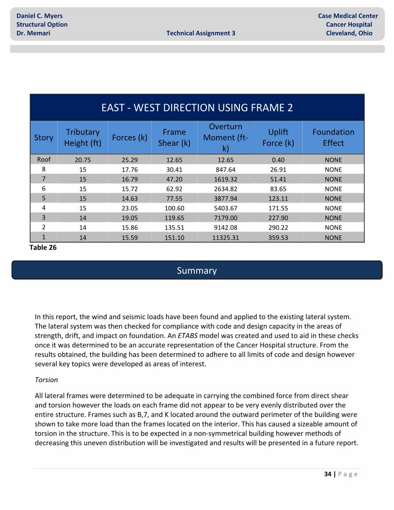
EAST ‐ WEST DIRECTION USING FRAME 2
Story Tributary Height (ft)
Forces (k) Frame Shear (k)
Overturn Moment (ft‐
k)
Uplift Force (k)
Foundation Effect
Roof 20.75 25.29 12.65 12.65 0.40 NONE 8 15 17.76 30.41 847.64 26.91 NONE 7 15 16.79 47.20 1619.32 51.41 NONE 6 15 15.72 62.92 2634.82 83.65 NONE 5 15 14.63 77.55 3877.94 123.11 NONE 4 15 23.05 100.60 5403.67 171.55 NONE 3 14 19.05 119.65 7179.00 227.90 NONE 2 14 15.86 135.51 9142.08 290.22 NONE 1 14 15.59 151.10 11325.31 359.53 NONE
In this report, the wind and seismic loads have been found and applied to the existing lateral system. The lateral system was then checked for compliance with code and design capacity in the areas of strength, drift, and impact on foundation. An ETABS model was created and used to aid in these checks once it was determined to be an accurate representation of the Cancer Hospital structure. From the results obtained, the building has been determined to adhere to all limits of code and design however several key topics were developed as areas of interest.
Torsion
All lateral frames were determined to be adequate in carrying the combined force from direct shear and torsion however the loads on each frame did not appear to be very evenly distributed over the entire structure. Frames such as B,7, and K located around the outward perimeter of the building were shown to take more load than the frames located on the interior. This has caused a sizeable amount of torsion in the structure. This is to be expected in a non‐symmetrical building however methods of decreasing this uneven distribution will be investigated and results will be presented in a future report.
Table 26
Summary

35 | P a g e
Daniel C. Myers Case Medical Center Structural Option Cancer Hospital Dr. Memari Technical Assignment 3 Cleveland, Ohio
Bracing Irregularity
In certain frames throughout the lateral structure, irregular bracing has been identified. This has caused stress reversals in the frames which hold these atypical configurations and aids in the uneven distribution of forces to the structure. Additional research will be conducted to determine the reason for these irregular bracing patterns and alternatives will be evaluated.
Member Strength
Critical members in the lateral structure of the Cancer Hospital have been checked for strength to resist loads both from lateral contributions as well as predetermined live and dead loads if applicable. Member strength capacity was found to be typically within 5‐10% of the required loads. Not only have the members been found to be adequate to carry the required loads, but also efficient in design.
Drift
The existing structure complies with all required drift limits for both wind and seismic loads however the maximum drift from wind in the north/south direction causes a significant drift of 3.14”. In a normal structure this would not be a concern however, due to the low amount of movement required in the imaging and surgery rooms, an effort should be made to decrease this value.
Overturning Moment
In addition to the direct lateral shear, axial forces from overturning moment were also considered. Though a spot check, the columns in the lateral frames were determined to capable of carrying this addition load. Uplift forces were evaluated against the gravity loads transferred axially to the foundation. Gravity loads were found to exceed the uplift force in all east/west frames and require no special foundation design however this is not the case in the north/south direction. In frame K it was found that uplift forces in the lower three levels exceeded the 469.5k gravity load. For this reason special foundation design for uplift force is required for frames in the north/south direction.
Table 27
AREAS OF CONCERN EAST‐WEST DIRECTION NORTH ‐ SOUTH DIRECTION
FRAME 2 FRAME 3 FRAME 7 FRAME B FRAME G FRAME K
Torsion NO NO YES YES NO YES
Irregularity NO NO YES YES YES YES
Strength NO NO NO NO NO NO
Drift NO NO NO YES YES YES
Overturning NO NO NO YES YES YES
36 | P a g e
Daniel C. Myers Case Medical Center Structural Option Cancer Hospital Dr. Memari Technical Assignment 3 Cleveland, Ohio
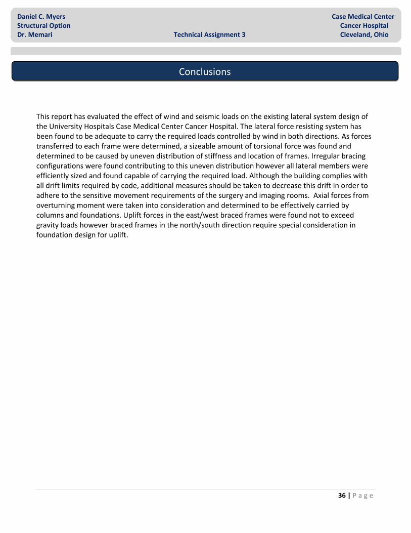
This report has evaluated the effect of wind and seismic loads on the existing lateral system design of the University Hospitals Case Medical Center Cancer Hospital. The lateral force resisting system has been found to be adequate to carry the required loads controlled by wind in both directions. As forces transferred to each frame were determined, a sizeable amount of torsional force was found and determined to be caused by uneven distribution of stiffness and location of frames. Irregular bracing configurations were found contributing to this uneven distribution however all lateral members were efficiently sized and found capable of carrying the required load. Although the building complies with all drift limits required by code, additional measures should be taken to decrease this drift in order to adhere to the sensitive movement requirements of the surgery and imaging rooms. Axial forces from overturning moment were taken into consideration and determined to be effectively carried by columns and foundations. Uplift forces in the east/west braced frames were found not to exceed gravity loads however braced frames in the north/south direction require special consideration in foundation design for uplift.
Conclusions

37 | P a g e
Daniel C. Myers Case Medical Center Structural Option Cancer Hospital Dr. Memari Technical Assignment 3 Cleveland, Ohio
Load Calculation
Appendix A

38 | P a g e
Daniel C. Myers Case Medical Center Structural Option Cancer Hospital Dr. Memari Technical Assignment 3 Cleveland, Ohio
Load Calculation

39 | P a g e
Daniel C. Myers Case Medical Center Structural Option Cancer Hospital Dr. Memari Technical Assignment 3 Cleveland, Ohio
Load Calculation
40 | P a g e
Daniel C. Myers Case Medical Center Structural Option Cancer Hospital Dr. Memari Technical Assignment 3 Cleveland, Ohio
Load Calculation

41 | P a g e
Daniel C. Myers Case Medical Center Structural Option Cancer Hospital Dr. Memari Technical Assignment 3 Cleveland, Ohio
Load Calculation
42 | P a g e
Daniel C. Myers Case Medical Center Structural Option Cancer Hospital Dr. Memari Technical Assignment 3 Cleveland, Ohio
Load Calculation

43 | P a g e
Daniel C. Myers Case Medical Center Structural Option Cancer Hospital Dr. Memari Technical Assignment 3 Cleveland, Ohio
Load Calculation

44 | P a g e
Daniel C. Myers Case Medical Center Structural Option Cancer Hospital Dr. Memari Technical Assignment 3 Cleveland, Ohio
Load Calculation

45 | P a g e
Daniel C. Myers Case Medical Center Structural Option Cancer Hospital Dr. Memari Technical Assignment 3 Cleveland, Ohio
Load Calculation

46 | P a g e
Daniel C. Myers Case Medical Center Structural Option Cancer Hospital Dr. Memari Technical Assignment 3 Cleveland, Ohio
Spreadsheet Output
TOTAL SEISMIC FORCE NORTH ‐ SOUTH
Level EAST ‐ WEST DIRECTION NORTH ‐ SOUTH DIRECTION
FRAME 2 FRAME 3 FRAME 7 FRAME B FRAME G FRAME K
Roof 20.36932607 21.56785884 0 ‐0.549344044 0.298730804 1.071777902
8th 15.5212867 14.87275517 0 ‐0.501322498 0.31025725 0.634134247
7th 17.05829206 16.38646407 0 ‐0.508500929 0.28024085 0.750895885
6th 14.68712219 14.32656251 0 ‐0.486185135 0.238875694 0.608592303
5th 12.14270545 11.63532225 0 ‐0.453392766 0.147399044 0.471454719
4th 8.268199527 8.173406641 3.369772703 ‐2.922586248 1.239717661 2.480503729
3rd 7.637410594 7.594189693 3.412078417 ‐2.297061468 0.973349584 2.768834177
2nd 5.604178091 6.060909504 1.486765488 ‐3.159787712 1.088180124 0.193033484
1ST 2.450163227 2.252580484 0.90022316 ‐0.745150204 0.307466705 0.808227125
SEISMIC DIRECT SHEAR NORTH ‐ SOUTH Level X ‐ DIRECTION Y ‐ DIRECTION
FRAME 2 FRAME 3 FRAME 7 FRAME B FRAME G FRAME K
Roof 20.09988694 21.47011306 0 0 0 0
8th 15.2624249 14.7875751 0 0 0 0
7th 16.76898915 16.29101085 0 0 0 0
6th 14.42224502 14.23775498 0 0 0 0
5th 11.9335325 11.5664675 0 0 0 0
4th 7.320239748 7.829078977 4.800681275 0 0 0
3rd 6.775440729 7.279659574 4.824899696 0 0 0
2nd 4.705654535 5.691799628 2.652545837 0 0 0
1ST 2.181499607 2.162145738 1.256354655 0 0 0
Appendix B

47 | P a g e
Daniel C. Myers Case Medical Center Structural Option Cancer Hospital Dr. Memari Technical Assignment 3 Cleveland, Ohio
Spreadsheet Output
SEISMIC TORSION FORCE NORTH ‐ SOUTH Level X ‐ DIRECTION Y ‐ DIRECTION
FRAME 2 FRAME 3 FRAME 7 FRAME B FRAME G FRAME K
Roof 0.269439127 0.09774578 0 ‐0.549344044 0.298730804 1.071777902
8th 0.2588618 0.085180077 0 ‐0.501322498 0.31025725 0.634134247
7th 0.289302907 0.09545322 0 ‐0.508500929 0.28024085 0.750895885
6th 0.264877166 0.088807532 0 ‐0.486185135 0.238875694 0.608592303
5th 0.209172956 0.068854748 0 ‐0.453392766 0.147399044 0.471454719
4th 0.947959779 0.344327664 ‐1.430908573 ‐2.922586248 1.239717661 2.480503729
3rd 0.861969864 0.314530118 ‐1.412821279 ‐2.297061468 0.973349584 2.768834177
2nd 0.898523556 0.369109876 ‐1.165780349 ‐3.159787712 1.088180124 0.193033484
1ST 0.26866362 0.090434746 ‐0.356131495 ‐0.745150204 0.307466705 0.808227125

48 | P a g e
Daniel C. Myers Case Medical Center Structural Option Cancer Hospital Dr. Memari Technical Assignment 3 Cleveland, Ohio
Spreadsheet Output
TOTAL SEISMIC FORCE EAST ‐ WEST
Level EAST ‐ WEST DIRECTION NORTH ‐ SOUTH DIRECTION
FRAME 2 FRAME 3 FRAME 7 FRAME B FRAME G FRAME K
Roof 0.269439127 0.09774578 0 9.582275347 15.17445845 17.63443087
8th 0.2588618 0.085180077 0 7.553154181 13.76904165 9.170873172
7th 0.289302907 0.09545322 0 8.365923304 13.48540003 11.73131247
6th 0.264877166 0.088807532 0 8.004567798 11.50255442 9.514160646
5th 0.209172956 0.068854748 0 8.095005838 7.650980622 7.919474537
4th 0.947959779 0.344327664 ‐1.430908573 4.061599736 9.238705045 7.447330362
3rd 0.861969864 0.314530118 ‐1.412821279 3.688846343 7.821763782 8.814512167
2nd 0.898523556 0.369109876 ‐1.165780349 3.424073616 7.217306244 0.530046036
1ST 0.26866362 0.090434746 ‐0.356131495 1.107369863 2.371330128 2.491843635
SEISMIC DIRECT SHEAR EAST ‐ WEST Level X ‐ DIRECTION Y ‐ DIRECTION
FRAME 2 FRAME 3 FRAME 7 FRAME B FRAME G FRAME K
Roof 0 0 0 10.13161939 14.87572764 16.56265296
8th 0 0 0 8.054476679 13.4587844 8.536738924
7th 0 0 0 8.874424233 13.20515918 10.98041659
6th 0 0 0 8.490752932 11.26367872 8.905568343
5th 0 0 0 8.548398604 7.503581579 7.448019817
4th 0 0 0 6.984185983 7.998987384 4.966826633
3rd 0 0 0 5.985907811 6.848414198 6.045677991
2nd 0 0 0 6.583861328 6.12912612 0.337012552
1ST 0 0 0 1.852520067 2.063863423 1.68361651

49 | P a g e
Daniel C. Myers Case Medical Center Structural Option Cancer Hospital Dr. Memari Technical Assignment 3 Cleveland, Ohio
Spreadsheet Output
SEISMIC TORSION FORCE EAST ‐ WEST Level X ‐ DIRECTION Y ‐ DIRECTION
FRAME 2 FRAME 3 FRAME 7 FRAME B FRAME G FRAME K
Roof 0.269439127 0.09774578 0 ‐0.549344044 0.298730804 1.071777902
8th 0.2588618 0.085180077 0 ‐0.501322498 0.31025725 0.634134247
7th 0.289302907 0.09545322 0 ‐0.508500929 0.28024085 0.750895885
6th 0.264877166 0.088807532 0 ‐0.486185135 0.238875694 0.608592303
5th 0.209172956 0.068854748 0 ‐0.453392766 0.147399044 0.471454719
4th 0.947959779 0.344327664 ‐1.430908573 ‐2.922586248 1.239717661 2.480503729
3rd 0.861969864 0.314530118 ‐1.412821279 ‐2.297061468 0.973349584 2.768834177
2nd 0.898523556 0.369109876 ‐1.165780349 ‐3.159787712 1.088180124 0.193033484
1ST 0.26866362 0.090434746 ‐0.356131495 ‐0.745150204 0.307466705 0.808227125

50 | P a g e
Daniel C. Myers Case Medical Center Structural Option Cancer Hospital Dr. Memari Technical Assignment 3 Cleveland, Ohio
Spreadsheet Output
TOTAL WIND FORCE NORTH ‐ SOUTH
Level EAST ‐ WEST DIRECTION NORTH SOUTH DIRECTION
FRAME 2 FRAME 3 FRAME 7 FRAME B FRAME G FRAME K
Roof 1.240278687 0.449942102 0 43.90534703 69.55184905 80.84165279
8th 1.115356341 0.367014903 0 32.39268463 59.07335952 39.35386719
7th 1.073500892 0.35419318 0 30.89918768 49.82558346 43.35283322
6th 1.073475697 0.35991297 0 32.29008863 46.41741085 38.40071999
5th 2.546582094 0.838274081 0 33.18909731 35.77230379 39.46593351
4th 1.539867382 0.559326408 ‐2.324370176 29.97269392 41.77878042 28.72068046
3rd 1.249788276 0.456043848 ‐2.048479354 23.23058438 31.79960367 30.84095022
2nd 1.654922722 0.679835622 ‐2.147162838 31.29110835 36.55193919 2.255153606
1ST 0.984812681 0.331497374 ‐1.305434699 18.05023047 24.27955935 21.84951896
WIND DIRECT SHEAR NORTH ‐ SOUTH Level X ‐ DIRECTION Y ‐ DIRECTION
FRAME 2 FRAME 3 FRAME 7 FRAME B FRAME G FRAME K
Roof 0 0 0 46.4340804 68.1767353 75.90805868
8th 0 0 0 34.55272997 57.7365559 36.62157663
7th 0 0 0 32.786055 48.78570866 40.56652384
6th 0 0 0 34.26046582 45.4493121 35.93425957
5th 0 0 0 38.70894041 33.97778995 33.72619465
4th 0 0 0 34.7201477 39.76498107 24.69134623
3rd 0 0 0 26.56114223 30.38832359 26.82635918
2nd 0 0 0 37.11088285 34.54770235 1.899619801
1ST 0 0 0 20.78165116 23.15251018 18.88688367

51 | P a g e
Daniel C. Myers Case Medical Center Structural Option Cancer Hospital Dr. Memari Technical Assignment 3 Cleveland, Ohio
Spreadsheet Output
WIND TORSION FORCE NORTH ‐ SOUTH Level X ‐ DIRECTION Y ‐ DIRECTION
FRAME 2 FRAME 3 FRAME 7 FRAME B FRAME G FRAME K
Roof 1.240278687 0.449942102 0 ‐2.528733362 1.375113754 4.933594104
8th 1.115356341 0.367014903 0 ‐2.160045343 1.336803615 2.73229056
7th 1.073500892 0.35419318 0 ‐1.886867323 1.039874801 2.78630938
6th 1.073475697 0.35991297 0 ‐1.97037719 0.968098747 2.46646042
5th 2.546582094 0.838274081 0 ‐5.519843091 1.79451384 5.739738859
4th 1.539867382 0.559326408 ‐2.324370176 ‐4.747453778 2.013799353 4.029334227
3rd 1.249788276 0.456043848 ‐2.048479354 ‐3.330557844 1.41128008 4.014591039
2nd 1.654922722 0.679835622 ‐2.147162838 ‐5.819774503 2.004236841 0.355533806
1ST 0.984812681 0.331497374 ‐1.305434699 ‐2.731420688 1.12704917 2.96263529

52 | P a g e
Daniel C. Myers Case Medical Center Structural Option Cancer Hospital Dr. Memari Technical Assignment 3 Cleveland, Ohio
Spreadsheet Output
TOTAL WIND FORCE EAST ‐ WEST
Level EAST ‐ WEST DIRECTION NORTH ‐ SOUTH DIRECTION
FRAME 2 FRAME 3 FRAME 7 FRAME B FRAME G FRAME K
Roof 25.2915617 27.78602982 0 2.226500091 ‐1.210760669 ‐4.34393277
8th 17.76544566 17.84090249 0 1.901379267 ‐1.176720982 ‐2.405097947
7th 16.79894642 16.92653353 0 1.661416972 ‐0.915626458 ‐2.453390145
6th 15.72352767 16.13863801 0 1.735045089 ‐0.852473823 ‐2.171878593
5th 14.63927911 14.72513341 0 1.815632604 ‐0.590266387 ‐1.887962545
4th 23.05226208 26.57163859 20.9948538 8.367937613 ‐3.549554801 ‐7.102168658
3rd 19.08961658 22.07367999 18.77487203 5.872138304 ‐2.488241371 ‐7.078163755
2nd 15.8654339 21.52010621 14.37170995 10.25719327 ‐3.536573248 ‐0.626618601
1ST 15.59301161 16.59091608 12.28118757 4.814865074 ‐1.9867279 ‐5.222443121
WIND DIRECT SHEAR EAST ‐ WEST Level X ‐ DIRECTION Y ‐ DIRECTION
FRAME 2 FRAME 3 FRAME 7 FRAME B FRAME G FRAME K
Roof 26.38360274 28.18219501 0 0 0 0
8th 18.74723775 18.16396725 0 0 0 0
7th 17.74418119 17.23840631 0 0 0 0
6th 16.66879275 16.45556475 0 0 0 0
5th 15.47692203 15.00086547 0 0 0 0
4th 25.76645685 27.55751623 16.89788193 0 0 0
3rd 21.29313021 22.87773525 15.16317854 0 0 0
2nd 18.7821899 22.71829788 10.58739422 0 0 0
1ST 17.32900936 17.17526954 9.980007105 0 0 0

53 | P a g e
Daniel C. Myers Case Medical Center Structural Option Cancer Hospital Dr. Memari Technical Assignment 3 Cleveland, Ohio
Spreadsheet Output
WIND TORSION FORCE EAST ‐ WEST Level
X ‐ DIRECTION Y ‐ DIRECTION
FRAME 2 FRAME 3 FRAME 7 FRAME B FRAME G FRAME K
Roof ‐1.092041039 ‐0.396165189 0 2.226500091 ‐1.210760669 ‐4.34393277
8th ‐0.981792085 ‐0.323064758 0 1.901379267 ‐1.176720982 ‐2.405097947
7th ‐0.945234771 ‐0.311872782 0 1.661416972 ‐0.915626458 ‐2.453390145
6th ‐0.945265072 ‐0.316926746 0 1.735045089 ‐0.852473823 ‐2.171878593
5th ‐0.837642919 ‐0.275732068 0 1.815632604 ‐0.590266387 ‐1.887962545
4th ‐2.714194764 ‐0.985877631 4.096971878 8.367937613 ‐3.549554801 ‐7.102168658
3rd ‐2.203513632 ‐0.804055259 3.61169349 5.872138304 ‐2.488241371 ‐7.078163755
2nd ‐2.916756 ‐1.198191676 3.784315731 10.25719327 ‐3.536573248 ‐0.626618601
1ST ‐1.735997755 ‐0.58435346 2.301180469 4.814865074 ‐1.9867279 ‐5.222443121

54 | P a g e
Daniel C. Myers Case Medical Center Structural Option Cancer Hospital Dr. Memari Technical Assignment 3 Cleveland, Ohio
Strength Checks
Appendix C

55 | P a g e
Daniel C. Myers Case Medical Center Structural Option Cancer Hospital Dr. Memari Technical Assignment 3 Cleveland, Ohio
Strength Checks
56 | P a g e
Daniel C. Myers Case Medical Center Structural Option Cancer Hospital Dr. Memari Technical Assignment 3 Cleveland, Ohio
Strength Checks

57 | P a g e
Daniel C. Myers Case Medical Center Structural Option Cancer Hospital Dr. Memari Technical Assignment 3 Cleveland, Ohio
Strength Checks

58 | P a g e
Daniel C. Myers Case Medical Center Structural Option Cancer Hospital Dr. Memari Technical Assignment 3 Cleveland, Ohio
Strength Checks
59 | P a g e
Daniel C. Myers Case Medical Center Structural Option Cancer Hospital Dr. Memari Technical Assignment 3 Cleveland, Ohio
Strength Checks

60 | P a g e
Daniel C. Myers Case Medical Center Structural Option Cancer Hospital Dr. Memari Technical Assignment 3 Cleveland, Ohio
Strength Checks

61 | P a g e
Daniel C. Myers Case Medical Center Structural Option Cancer Hospital Dr. Memari Technical Assignment 3 Cleveland, Ohio
Strength Checks

62 | P a g e
Daniel C. Myers Case Medical Center Structural Option Cancer Hospital Dr. Memari Technical Assignment 3 Cleveland, Ohio
Level 6 Floor Plan
Appendix D

63 | P a g e
Daniel C. Myers Case Medical Center Structural Option Cancer Hospital Dr. Memari Technical Assignment 3 Cleveland, Ohio
Level 6 Floor Plan

64 | P a g e
Daniel C. Myers Case Medical Center Structural Option Cancer Hospital Dr. Memari Technical Assignment 3 Cleveland, Ohio
Elevation

65 | P a g e
Daniel C. Myers Case Medical Center Structural Option Cancer Hospital Dr. Memari Technical Assignment 3 Cleveland, Ohio
Loading Diagram