Thomas Christen, ABB Corporate Research, ABB Switzerland ...
1473-1-8873 / 2CKA001473B8873 │ 18.04.2016
Technical Reference Manual ABB-free@home®
Compact combination 1/1gang with T13 SSA-F-1.1.2-508

Table of contents
Technical Reference Manual 1473-1-8873 / 2CKA001473B8873 │2
Table of contents
1 Information on the manual .......................................................................................................................................... 3 2 Safety .......................................................................................................................................................................... 4
2.1 Information and symbols used ........................................................................................................................ 4 2.2 Intended use ................................................................................................................................................... 5 2.3 Improper use .................................................................................................................................................. 5 2.4 Target group / Qualifications of personnel ...................................................................................................... 5 2.5 Safety instructions .......................................................................................................................................... 6 2.6 Environment ................................................................................................................................................... 7
3 Setup and function ...................................................................................................................................................... 8 3.1 Scope of supply .............................................................................................................................................. 9 3.2 Overview of types ........................................................................................................................................... 9 3.3 Functions ........................................................................................................................................................ 9 3.4 Device overview ........................................................................................................................................... 10
4 Technical data ........................................................................................................................................................... 11 4.1 Types of load ................................................................................................................................................ 11 4.2 Dimensional drawings .................................................................................................................................. 12
5 Connection and installation ....................................................................................................................................... 13 5.1 Planning instructions .................................................................................................................................... 13 5.2 Safety instructions ........................................................................................................................................ 13 5.3 Circuit diagrams ............................................................................................................................................ 14 5.4 Installation .................................................................................................................................................... 15
6 Commissioning ......................................................................................................................................................... 16 6.1 Allocation of devices and definition of channels ........................................................................................... 16 6.2 Setting options per channel .......................................................................................................................... 22 6.3 Links ............................................................................................................................................................. 25
7 Update ...................................................................................................................................................................... 27 8 Operation .................................................................................................................................................................. 27 9 Maintenance ............................................................................................................................................................. 27
9.1 Cleaning ....................................................................................................................................................... 27 10 Notes ......................................................................................................................................................................... 28 11 Index ......................................................................................................................................................................... 29
Information on the manual
Technical Reference Manual 1473-1-8873 / 2CKA001473B8873 │3
1 Information on the manual
Please read this manual carefully and observe the information it contains. This will assist you in preventing injuries and damage to property, and ensure both reliable operation and a long service life for the device.
Please keep this manual in a safe place.
If you pass the device on, also pass on this manual along with it.
ABB accepts no liability for any failure to observe the instructions in this manual.
If you require additional information or have questions about the device, please contact ABB or visit our Internet site at:
www.abb.ch/freeathome
Safety
Technical Reference Manual 1473-1-8873 / 2CKA001473B8873 │4
2 Safety
The device has been constructed according to the latest valid regulations governing technology and is operationally reliable. It has been tested and left the factory in a technically safe and reliable state.
However, residual hazards remain. Read and adhere to the safety instructions to prevent hazards of this kind.
ABB accepts no liability for any failure to observe the safety instructions.
2.1 Information and symbols used
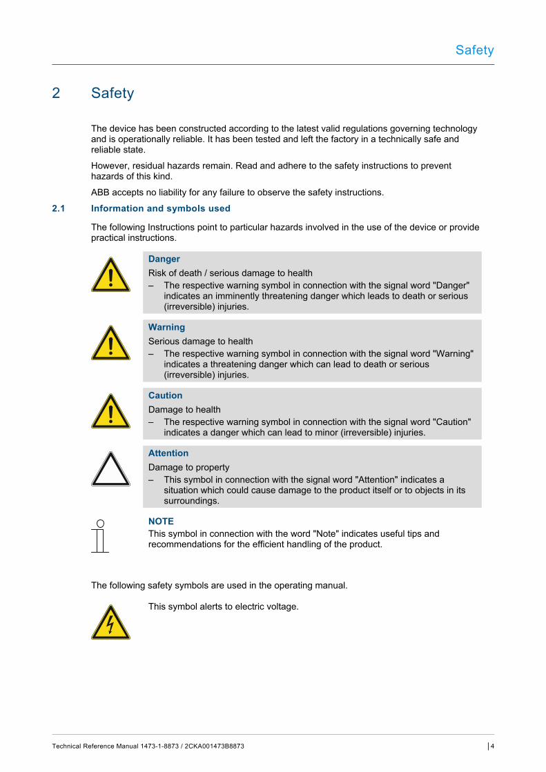
The following Instructions point to particular hazards involved in the use of the device or provide practical instructions.
Danger Risk of death / serious damage to health – The respective warning symbol in connection with the signal word "Danger"
indicates an imminently threatening danger which leads to death or serious (irreversible) injuries.
Warning Serious damage to health – The respective warning symbol in connection with the signal word "Warning"
indicates a threatening danger which can lead to death or serious (irreversible) injuries.
Caution Damage to health – The respective warning symbol in connection with the signal word "Caution"
indicates a danger which can lead to minor (irreversible) injuries.
Attention Damage to property – This symbol in connection with the signal word "Attention" indicates a
situation which could cause damage to the product itself or to objects in its surroundings.
NOTE This symbol in connection with the word "Note" indicates useful tips and recommendations for the efficient handling of the product.
The following safety symbols are used in the operating manual.
This symbol alerts to electric voltage.
Safety
Technical Reference Manual 1473-1-8873 / 2CKA001473B8873 │5
2.2 Intended use
This device is a sensor/switch actuator unit for decentralized flush-mounted installation.
The device is intended for the following: ■ Switching 230 V loads ■ Operation according to the listed technical data ■ Installation in dry interior rooms and suitable flush-mounted boxes ■ Use with the connecting options available on the device
The intended use also includes adherence to all specifications in this manual.
2.3 Improper use
Each use not listed in Chapter 2.2 “Intended use“ on page 5 is deemed improper use and can lead to personal injury and damage to property.
ABB is not liable for damages caused by use deemed contrary to the intended use of the device. The associated risk is borne exclusively by the user/operator.
The device is not intended for the following: ■ Unauthorized structural changes ■ Repairs ■ Outdoor use ■ Insert with an additional bus coupler
2.4 Target group / Qualifications of personnel
Installation, commissioning and maintenance of the device must only be carried out by trained and properly qualified electrical installers.
The electrical installer must have read and understood the manual and follow the instructions provided.
The electrical installer must adhere to the valid national regulations in his/her country governing the installation, functional test, repair and maintenance of electrical products.
The electrical installer must be familiar with and correctly apply the "five safety rules" (DIN VDE 0105, EN 50110):
1. Disconnect 2. Secure against being re-connected 3. Ensure there is no voltage 4. Connect to earth and short-circuit 5. Cover or barricade adjacent live parts
Safety
Technical Reference Manual 1473-1-8873 / 2CKA001473B8873 │6
2.5 Safety instructions
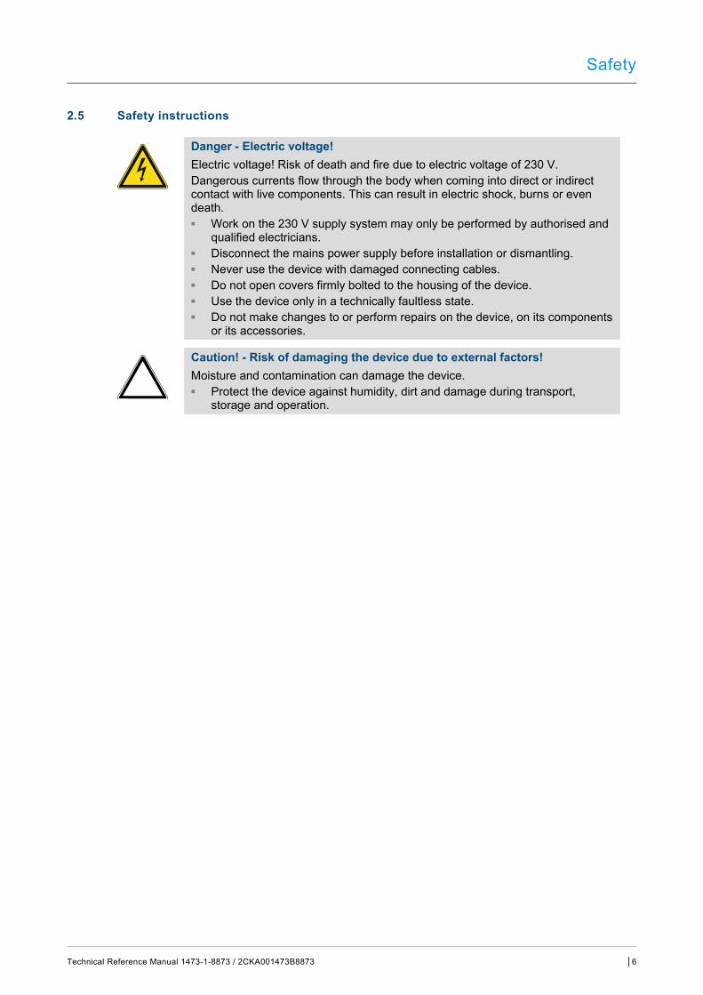
Danger - Electric voltage! Electric voltage! Risk of death and fire due to electric voltage of 230 V. Dangerous currents flow through the body when coming into direct or indirect contact with live components. This can result in electric shock, burns or even death. ■ Work on the 230 V supply system may only be performed by authorised and
qualified electricians. ■ Disconnect the mains power supply before installation or dismantling. ■ Never use the device with damaged connecting cables. ■ Do not open covers firmly bolted to the housing of the device. ■ Use the device only in a technically faultless state. ■ Do not make changes to or perform repairs on the device, on its components
or its accessories.
Caution! - Risk of damaging the device due to external factors! Moisture and contamination can damage the device. ■ Protect the device against humidity, dirt and damage during transport,
storage and operation.
Safety
Technical Reference Manual 1473-1-8873 / 2CKA001473B8873 │7
2.6 Environment
Consider the protection of the environment! Used electric and electronic devices must not be disposed of with domestic waste. – The device contains valuable raw materials which can be recycled.
Therefore, dispose of the device at the appropriate collecting depot.
All packaging materials and devices bear the markings and test seals for proper disposal. Always dispose of the packaging material and electric devices and their components via the authorized collecting depots and disposal companies.
The products meet the legal requirements, in particular the laws governing electronic and electrical devices and the REACH ordinance.
(EU Directive 2002/96/EC WEEE and 2002/95/EC RoHS)
(EU REACH ordinance and law for the implementation of the ordinance (EC) No.1907/2006).

Setup and function
Technical Reference Manual 1473-1-8873 / 2CKA001473B8873 │8
3 Setup and function
Fig. 1: Product overview
[1] Flush-mounted insert, 1/1gang with T13 [2] Support ring [3] Cover frame [4] Cover plate with push-buttons and socket outlet
This device is a sensor/switch actuator unit with socket outlet for decentralized flush-mounted installation. The device serves both as control element and as actuator for switching electric loads.
Sensor and actuator are combined in a flush-mounted insert [1]. The sensor and switching channels have been pre-programmed at the point of delivery (push-buttons left/right: off/on). This configuration can be changed and adapted.
After activating the bus voltage and connecting the load, the load can be switched directly on the control element. The integrated bus coupler makes possible the connection to the free@home bus line.
Additional product features: ■ Green LEDs as light for orientation and status indication. ■ Exchangeable push-buttons with the corresponding icons.

Setup and function
Technical Reference Manual 1473-1-8873 / 2CKA001473B8873 │9
3.1 Scope of supply
The scope of supply includes the following: ■Flush-mounted insert [1]
And, depending on the model: ■ Support ring [2] ■ Cover frame [3] ■ Cover plate with push-buttons and socket outlet [4]
See Figure on Page 8.
NOTE Depending on their use, the push-buttons can be selected with different printing. Additional information about the switch ranges is available in the electronic catalogue (www.busch-jaeger-catalogue.com).
3.2 Overview of types
Sensor channels Actuator channels Product name Switching load
1
1 Compact combination
1/1gang with T13 1 x 2300 W
Table 1: Overview of types
3.3 Functions
The following table provides an overview of the possible functions and applications of the device:
Icon of the operating surface Information
Name: Sensor
Type: Sensor
Made available by: Sensor/switch actuator
Function: Control element for the control of free@home functions
Name: Switch actuator
Type: Actuator
Made available by: Sensor/switch actuator
Function: Switches connected loads
Table 2: Overview of functions
Setup and function
Technical Reference Manual 1473-1-8873 / 2CKA001473B8873 │10
3.4 Device overview
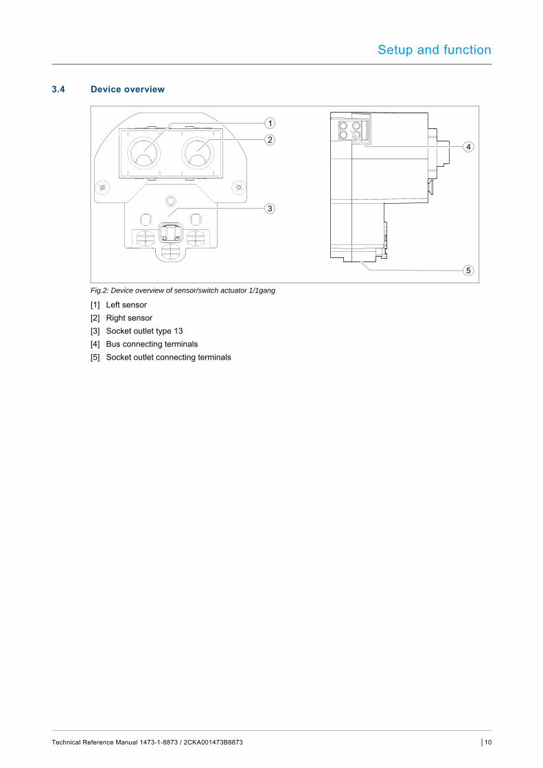
Fig.2: Device overview of sensor/switch actuator 1/1gang
[1] Left sensor [2] Right sensor [3] Socket outlet type 13 [4] Bus connecting terminals [5] Socket outlet connecting terminals

Technical data
Technical Reference Manual 1473-1-8873 / 2CKA001473B8873 │11
4 Technical data
Designation Value
Power Supply 24 V DC (via bus line)
Bus subscribers 1 (12 mA)
Bus connection
Connecting terminal 0.4 - 0.8 mm
Line type J-Y(St)Y, 2 x 2 x 0.8 mm
Wire stripping 6 - 7 mm
Maximum load 10 AX
Switched load line Connection 230 V AC, 50/60 Hz
Screw terminals 2 x 2.5 mm2 rigid 2 x 1.5 mm2 flexible
Switching capacity 1 x 10 Ax
Socket outlet type 13 10 A, 250 V AC
Protection type IP20
Ambient temperature -5°C - +45°C
Storage temperature -20°C - +70°C
Table 3: Technical data
4.1 Types of load
Load type Maximum load
2300 W
2300 W
2300 VA
2300 W
(CFLi)
2300 W
Typical 100 W
LEDi 230 V~
Typical 100 W
Table 4: Types of load
Technical data
Technical Reference Manual 1473-1-8873 / 2CKA001473B8873 │12
4.2 Dimensional drawings
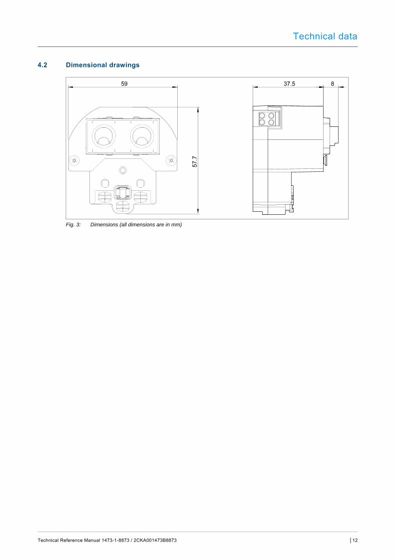
Fig. 3: Dimensions (all dimensions are in mm)
Connection and installation
Technical Reference Manual 1473-1-8873 / 2CKA001473B8873 │13
5 Connection and installation
5.1 Planning instructions
NOTE Planning and application instructions for the system are available in system manual for ABB-free@home®. This can be downloaded via www.abb.ch/freeathome.
5.2 Safety instructions
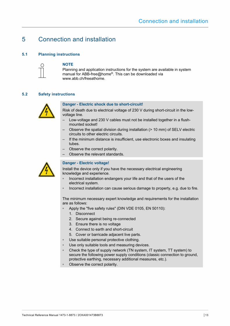
Danger - Electric shock due to short-circuit! Risk of death due to electrical voltage of 230 V during short-circuit in the low-voltage line. – Low-voltage and 230 V cables must not be installed together in a flush-
mounted socket! – Observe the spatial division during installation (> 10 mm) of SELV electric
circuits to other electric circuits. – If the minimum distance is insufficient, use electronic boxes and insulating
tubes. – Observe the correct polarity. – Observe the relevant standards.
Danger - Electric voltage! Install the device only if you have the necessary electrical engineering knowledge and experience. ■ Incorrect installation endangers your life and that of the users of the
electrical system. ■ Incorrect installation can cause serious damage to property, e.g. due to fire. The minimum necessary expert knowledge and requirements for the installation are as follows: ■ Apply the "five safety rules" (DIN VDE 0105, EN 50110):
1. Disconnect 2. Secure against being re-connected 3. Ensure there is no voltage 4. Connect to earth and short-circuit 5. Cover or barricade adjacent live parts.
■ Use suitable personal protective clothing. ■ Use only suitable tools and measuring devices. ■ Check the type of supply network (TN system, IT system, TT system) to
secure the following power supply conditions (classic connection to ground, protective earthing, necessary additional measures, etc.).
■ Observe the correct polarity.

Connection and installation
Technical Reference Manual 1473-1-8873 / 2CKA001473B8873 │14
5.3 Circuit diagrams
Fig. 4: Electrical connection
[1] Support ring [2] Device insert [3] 230 V power cord [4] Flush-mounted installation box [5] Bus line
Ⓐ Designation of channel for software commissioning (example)

Connection and installation
Technical Reference Manual 1473-1-8873 / 2CKA001473B8873 │15
5.4 Installation
NOTE They may only be installed in dry interior rooms in flush-mounted boxes. Observe the currently valid regulations.
To install the device, perform the following steps:
1. Pull off the identification label and glue it into the device plan (at System Access Point).
2. Connect the bus line with the bus connection terminal [1] (see chapter 5.3 “Circuit diagrams“ on page 14). Observe the correct polarity.
3. Connect the 230 V power cord to the socket outlet connection [2].
4. Turn the device into the correct installation position. The socket outlet must be at the bottom.
5. Insert the device into the flush-mounted box and screw the device on.
6. Attach the cover frame [4] together with the cover plate [5] to the Support ring [3] and screw the cover plate on.
Fig. 5: Connection
Fig. 6: Installation
Commissioning
Technical Reference Manual 1473-1-8873 / 2CKA001473B8873 │16
6 Commissioning
Commissioning of the device is always carried out via the Web-based surface of the System Access Point. It is assumed that the basic commissioning steps of the overall system have already been carried out. Knowledge about the Web-based commissioning software of the System Access Point is assumed.
The System Access Point establishes the connection between the free@home participants and the smartphone, tablet or PC. The System Access Point is used to identify and program the participants during commissioning.
Devices which are physically connected to the free@home bus, log themselves automatically into the System Access Point. They transmit information about their type and supported functions (see chapter 3.3 “Functions“ on page 9).
During initial commissioning all devices are given a universal name, e.g. "Sensor/switch actuator 1/1gang". The installer must assign names that are practical and specific for the system, e.g. in "Living room ceiling light".
The devices must be parameterised for the use of additional functions.
NOTE General information about commissioning and parameterization is available in the technical reference manual and the online Help of the System Access Point.
6.1 Allocation of devices and definition of channels
The devices connected to the system must be identified, i.e. they are allocated to a room according to their function and are given a practical name.
The allocation is made via the allocation function of the Web-based user interface of the System Access Point.

Commissioning
Technical Reference Manual 1473-1-8873 / 2CKA001473B8873 │17
6.1.1 Add device
Fig. 7: Allocation - Start screen
Fig. 8: Add device
■In the "Add device" bar select the desired application and pull the icon via drag-and-drop onto the floor plan in the working area.
A window opens which lists all the devices suitable for the application selected.

Commissioning
Technical Reference Manual 1473-1-8873 / 2CKA001473B8873 │18
Fig. 9: Allocation of devices
The device can be identified via the serial number or via switching.
Identification via serial number
Commissioning
Technical Reference Manual 1473-1-8873 / 2CKA001473B8873 │19
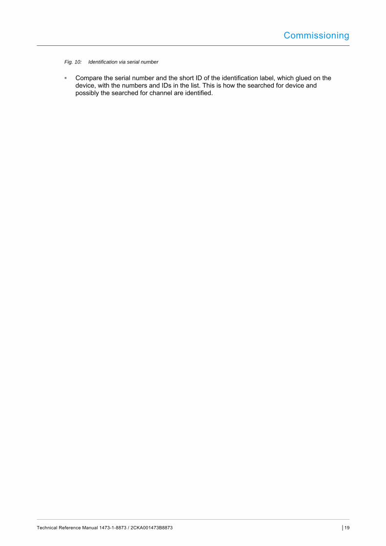
Fig. 10: Identification via serial number
■ Compare the serial number and the short ID of the identification label, which glued on the device, with the numbers and IDs in the list. This is how the searched for device and possibly the searched for channel are identified.
Commissioning
Technical Reference Manual 1473-1-8873 / 2CKA001473B8873 │20
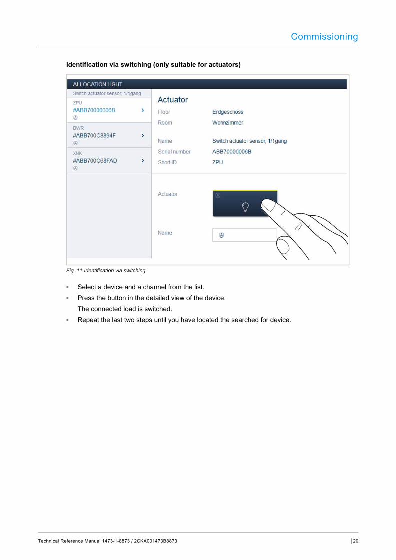
Identification via switching (only suitable for actuators)
Fig. 11 Identification via switching
■ Select a device and a channel from the list. ■ Press the button in the detailed view of the device.
The connected load is switched. ■ Repeat the last two steps until you have located the searched for device.
Commissioning
Technical Reference Manual 1473-1-8873 / 2CKA001473B8873 │21
Assigning a name
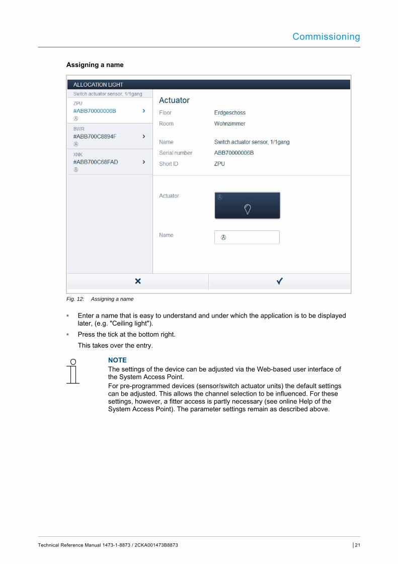
Fig. 12: Assigning a name
■ Enter a name that is easy to understand and under which the application is to be displayed later, (e.g. "Ceiling light").
■ Press the tick at the bottom right. This takes over the entry.
NOTE The settings of the device can be adjusted via the Web-based user interface of the System Access Point. For pre-programmed devices (sensor/switch actuator units) the default settings can be adjusted. This allows the channel selection to be influenced. For these settings, however, a fitter access is partly necessary (see online Help of the System Access Point). The parameter settings remain as described above.
Commissioning
Technical Reference Manual 1473-1-8873 / 2CKA001473B8873 │22
6.2 Setting options per channel
General settings and special parameter settings must be made for each channel.
The settings are made via the allocation function of the Web-based user interface of the System Access Point.
Select device
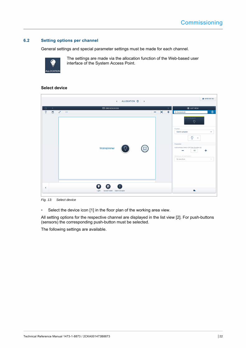
Fig. 13: Select device
■ Select the device icon [1] in the floor plan of the working area view.
All setting options for the respective channel are displayed in the list view [2]. For push-buttons (sensors) the corresponding push-button must be selected.
The following settings are available.
Commissioning
Technical Reference Manual 1473-1-8873 / 2CKA001473B8873 │23
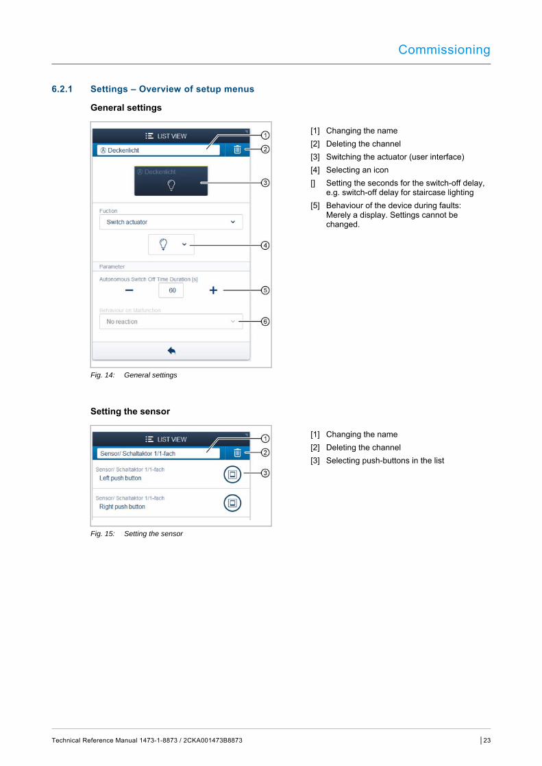
6.2.1 Settings – Overview of setup menus
General settings
[1] Changing the name [2] Deleting the channel [3] Switching the actuator (user interface) [4] Selecting an icon [] Setting the seconds for the switch-off delay,
e.g. switch-off delay for staircase lighting [5] Behaviour of the device during faults:
Merely a display. Settings cannot be changed.
Fig. 14: General settings
Setting the sensor
[1] Changing the name [2] Deleting the channel [3] Selecting push-buttons in the list
Fig. 15: Setting the sensor
Commissioning
Technical Reference Manual 1473-1-8873 / 2CKA001473B8873 │24
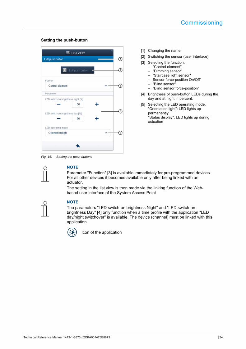
Setting the push-button
[1] Changing the name [2] Switching the sensor (user interface) [3] Selecting the function.
– "Control element" – "Dimming sensor" – "Staircase light sensor" – Sensor force-position On/Off" – "Blind sensor" – "Blind sensor force-position"
[4] Brightness of push-button LEDs during the day and at night in percent.
[5] Selecting the LED operating mode. "Orientation light": LED lights up permanently. "Status display": LED lights up during actuation
Fig. 16: Setting the push-buttons
NOTE Parameter "Function" [3] is available immediately for pre-programmed devices. For all other devices it becomes available only after being linked with an actuator. The setting in the list view is then made via the linking function of the Web-based user interface of the System Access Point.
NOTE The parameters "LED switch-on brightness Night" and "LED switch-on brightness Day" [4] only function when a time profile with the application "LED day/night switchover" is available. The device (channel) must be linked with this application.
Icon of the application

Commissioning
Technical Reference Manual 1473-1-8873 / 2CKA001473B8873 │25
6.3 Links
The sensor/switch actuator units created via the allocation function can now be linked with each other. This allows simple switch-off or two-way circuits to be implemented.
The linking in the list view is made via the linking function of the Web-based user interface of the System Access Point.
NOTE For pre-programmed devices (switch actuator units) a link is automatically established between actuator and sensor, since they are combined in the one device.
6.3.1 Linking actuator and sensor
Fig. 17: Linking actuator and sensor
1. On the working area select the sensor [1] that is to be linked with the actuator. . Select the actuator [2] that is to be served by the sensor. 2. Press "Save" at the bottom right to take over the entries.
A blue connecting line indicates the link between the two devices. The configuration is now transmitted automatically to the devices. The transmission can, depending on the number of affected devices, take a number of seconds. During the transmission a progress bar is displayed around the devices affected.
Commissioning
Technical Reference Manual 1473-1-8873 / 2CKA001473B8873 │26
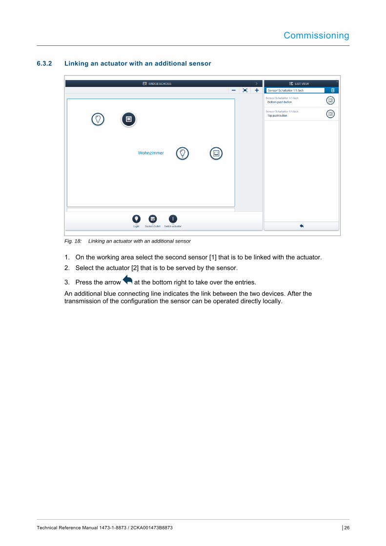
6.3.2 Linking an actuator with an additional sensor
Fig. 18: Linking an actuator with an additional sensor
1. On the working area select the second sensor [1] that is to be linked with the actuator. 2. Select the actuator [2] that is to be served by the sensor.
3. Press the arrow at the bottom right to take over the entries.
An additional blue connecting line indicates the link between the two devices. After the transmission of the configuration the sensor can be operated directly locally.
Update
Technical Reference Manual 1473-1-8873 / 2CKA001473B8873 │27
7 Update
A firmware update is carried out via the Web-based user interface of the System Access Point.
8 Operation
Operation is carried out by pressing the individual push-buttons (not included in the scope of delivery). The function of the push-buttons is fixed via the assigned application or its pre-programming and its parameter settings.
Extensive applications are available for the push-buttons (control buttons).
9 Maintenance
The device is maintenance-free. In case of damage, e.g. during transport or storage), do not perform repairs. Once the device is opened, the warranty is void.
Access to the device must be guaranteed for operation, testing, inspection, maintenance and repairs (according to DIN VDE 0100-520).
9.1 Cleaning
Caution! - Risk of damaging the device! ■ When spraying on cleaning agents, these can enter the device through
crevices. – Do not spray cleaning agents directly onto the device.
■ Aggressive cleaning agents can damage the surface of the device. – Never use caustic agents, abrasive agents or solvents.
Clean dirty devices with a soft dry cloth.
– If this is insufficient, the cloth can be moistened slightly with a soap solution.
Notes
Technical Reference Manual 1473-1-8873 / 2CKA001473B8873 │28
10 Notes
Index
Technical Reference Manual 1473-1-8873 / 2CKA001473B8873 │29
11 Index
A Actuator ................................................................................. 9 Add device ........................................................................... 17 Allocation of devices ............................................................ 16
B Bus coupler ............................................................................ 8
C Circuit diagrams ............................................................. 14, 15 Cleaning .............................................................................. 27 Commissioning .................................................................... 16 Connection and installation ................................................. 13
D Device overview .................................................................. 10 Dimensional drawings ......................................................... 12
E Environment .......................................................................... 7
F Firmware update .................................................................. 27 Functions ......................................................................... 9, 16
G General settings .................................................................. 23
I Identification ........................................................................ 18 Identification label .......................................................... 15, 19 Improper use ......................................................................... 5 Information and symbols used ............................................... 4 Information on the manual ..................................................... 3 Initial commissioning ........................................................... 16 Installation ........................................................................... 15 Intended use .......................................................................... 5
L LED ........................................................................................ 8 Liability ................................................................................... 3 Links .................................................................................... 25
actuator ........................................................................... 25 Additional sensors .......................................................... 26 sensor ............................................................................. 25
M Maintenance ........................................................................27
N Notes ....................................................................................28
O Operation .............................................................................27 Overview of types ..................................................................9
P Planning instructions ............................................................13 Power Supply .......................................................................11 Protection type .....................................................................11
Q Qualification of personnel ......................................................5
S Safety .....................................................................................4 Safety instructions ............................................................6, 13 Scope of supply .....................................................................9 Select device ........................................................................22 Sensor ....................................................................................9 Serial number .......................................................................18 Setting the sensor ................................................................23 Settings ................................................................................23 Setup and function .................................................................8 Setup menus ........................................................................23 Socket outlet ..........................................................................8 Switching capacity ...............................................................11 System Access Point ...........................................................16
T Target group ..........................................................................5 Technical data ......................................................................11 Temperature
ambient ...........................................................................11 storage ............................................................................11
Types of load .......................................................................11
U Update .................................................................................27

Index
Technical Reference Manual 1473-1-8873 / 2CKA001473B8873 │30
A member of the ABB Group ABB Switzerland AG Low-voltage products Brown Boveri Platz 3 5400 Baden Tel.: +41 58 586 06 53 www.ABB.ch/gebaeudeautomation
NOTE We reserve the right to at all times make technical changes as well as changes to the contents of this document without prior notice. The detailed specifications agreed upon apply for orders. ABB accepts no responsibility for errors or incompleteness in this document. We reserve all rights in this document and in the subject matter and illustrations contained therein. The document and its contents, or extracts thereof, must not be reproduced, transmitted or reused by third parties without prior written consent by ABB. Copyright© 2016 Busch-Jaeger Elektro GmbH All rights reserved
Tech
nica
l Ref
eren
ce M
anua
l 14
73-1
-887
3 / 2
CK
A00
1473
B88
73