Technical Papers in Hydrology 24 · 2014-12-29 · 3.1 Pitot-Prandtl tube 3.2 Venturi meter for...
79
Transcript of Technical Papers in Hydrology 24 · 2014-12-29 · 3.1 Pitot-Prandtl tube 3.2 Venturi meter for...


Technical Papers in Hydrology 24

In this series:
1. Perennial ice and snow masses. A guide for compilation and assemblage of data for a world inventory. 2. Seasonal snow cover. A guide for measurement, compilation and assemblage of data. 3 . Variations of existing glaciers. A guide to international practices for their measurement. 4 . Antarctic glaciology in the International Hydrological Decade. 5. Combined heat, ice and water balances at selected glacier basins. A guide for compilation and
assemblage of data for glacier mass balance measurements. 6. Textbooks on hydrology—analyses and synoptic tables of contents of selected textbooks. 7. Scientific framework of world water balance. 8. Flood studies-an international guide for collection and processing of data. 9. Guide to world inventory of sea, lake, and river ice.
10. Curricula and syllabi in hydrology. 11. Teaching aids in hydrology. 12. Ecology of water weeds in the netropics. 13. The teaching of hydrology. 14. Legends for geohydrochemical maps. 15. Research on urban hydrology, vol. 1. 16. Research on urban hydrology, vol 2. 17. Hydrological problems arising from the development of energy. 18. Urban hydrological modelling and catchment research, international summary. 19. Remote sensing of snow and ice. 20. Predicting effects of power plant once-through cooling on aquatic systems. 21. Research on urban hydrology, Vol. 3 . 22. Curricula and syllabi in hydrology. 23. Dispersion and self-purification of pollutants in surface water systems. 24. Experimental facilities in water resources education. 25. Teaching the systems approach to water resources development. 26. Study of the relationship between water quality and sediment transport.

A contribution to the International Hydrological Programme
Experimental facilities in water resources education
Report by a team of authors on IHP-II Project B.2.1.4, "Experimental facilities in water resources education"
Unesco

T h e designations employed and the presentation of the material do not imply the expression of any opinion whatsoever on the part of Unesco concerning the legal status of any country or territory, or of its authorities, or concerning the frontiers of any country or territory.
Published in 1983 by the United Nations Educational, Scientific and Cultural Organization 7, place de Fontcnoy, 75700 Paris Printed by Imprimerie de la Manutention, Mayenne
ISBN 92-3-102107-9
©Unesco 1983
Printed in France
Preface
Although the total amount of water on earth is generally assumed to have remained virtually constant, the rapid growth of population, together with the extension of irrigated agriculture and industrial development, are stressing the quantity and quality aspects of the natural system. Because of the increasing problems, m a n has begun to realize that he can no longer follow a "use and discard" philosophy—either with water resources or any other natural resource. A s a result, the need for a consistent policy of rational management of water resources has become evident.
Rational water management, however, should be founded upon a thorough understanding of water «availability and movement. Thus, as a contribution to the solution of the world's water problems, Unesco, in 1965, began the first world-wide programme of studies of the hydrological cycle—the International Hydrological Decade (I H D ) . The research programme was complemented by a major effort in the field of hydrological education and training. The activities undertaken during the Decade proved to be of great interest and value to M e m b e r States. By the end ofthat period, a majority of Unesco 's M e m b e r States had formed I H D National Committees to carry out relevant national activities and to participate in regional and international co-operation within the I H D programme. The knowledge of the world's water resources had substantially improved. Hydrology became widely recognized as an independent professional option and facilities for the training of hydrologists had been developed.
Conscious of the need to expand upon the efforts initiated during the International Hydrological Decade and, following the recommendations of M e m b e r States, Unesco, in 1975, launched a new long-term intergovernmental programme, the International Hydrological Programme (IHP), to follow the Decade.
Although the I H P is basically a scientific and educational programme, Unesco has been aware from the beginning of a need to direct its activities toward the practical solutions of the world's very real water resources problems. Accordingly,, and in line with the recommendations of the 1977 United Nations Water Conference, the objectives of the International Hydro-logical Programme have been gradually expanded in order to cover not only hydrological processes considered in interrelationship with the environment and h u m a n activities, but also the scientific aspects of multi-purpose utilization and conservation of water resources to meet the needs of economic and social development. Thus, while maintaining IHP's scientific concept, the objectives have shifted perceptibly towards a multidisciplinary approach to the assessment, planning, and rational m a n a gement of water resources.
A s part of Unesco 's contribution to the objectives of the I H P , two publication series are issued: "Studies and Reports in Hydrology" and "Technical Papers in Hydrology". In addition to these publications, and in order to expedite exchange of information in the areas in which it is most needed, works of a preliminary nature are issued in the form of Technical Documents.
The "Technical Papers in hydrology" series, to which this volume belongs, is intended to provide a means for the exchange of information on hydrological techniques and for the coordination of research and data collection. Unesco uses this series as a means of bringing together and making k n o w n the experience accumulated by hydrologists throughout the world.

Contents
FOREWORD 13
1. INTRODUCTION 15
1.1 The importance of the experimental experience in water resources education 15
1.1.1 Understanding the hydrologie cycle 15
1.1.2 Study of hydraulics and hydrological processes 19
1.1.3 Role in the educational process 19
1.2 The necessity of experimental practice 20
1.2.1 Understanding of theory 20
1.2.2 Training of practitioners 20
1.2.3 The gathering of data and its improvement for water resources design needs 21
1.2.4 The gathering of data for operation and management
of water resources projects 21
1.3 Water resources data 22
1.3.1 Definition 22
1.3.2 Purpose of data 22
1.3.3 Quality.of data 23
1.4 The objectives of the monograph 23
1.4.1 Scope of hydraulics and hydrology facilities 23
1.4.2 Educational level of facilities 23
1.4.3 Suggestions for teachers 24
2. GENERAL CONCEPTS OF MEASUREMENTS 25
2.1 General 25
Definition and characteristics of measurements; 25 dimensions and units
Simple and derived measurements 26
Accuracy 26
Precision of instruments 26
Sources of error 26
Total accuracy 26
Temporal and spatial variability of water resources data 27
Water resources variables 27
The nature of water resources variables 27
Measurements and instruments for water resources variables 28
Data handling 28
Data collecting, reliability and reduction 28
Verification and correlation of measurements 29
HYDRAULICS LABORATORIES 31
General 31
The purpose of experimental hydraulics teaching 31
Classification of laboratory equipment and facilities 32
Operation of the hydraulic teaching facility 32
Measurement of physical properties 33
Liquid density 33
Viscosity 33
Surface tension measurement 34
General purpose equipment 34
Water level measuring equipment 34
Pressure measuring equipment 35
Velocity measuring equipment 35
Discharge measuring equipment 35
Classroom facilities 35
Energy law demonstration 39
Momentum law demonstration 39
Reynolds experiment 39
Open channel demonstration 39
3.5 Laboratory facilities 41
3.5.1 General layout 41
3.5.2 Flow in pipes 41
3.5.3 Flow in open channels 42
3.5.4 Hydraulic structures 42
3.5.5 Pumps and turbines 42
3.5.6 Hydraulic models 46
3.5.7 Flow visualisation 46
3.5.8 Calibration facilities 48
4. HYDROLOGICAL TEACHING FACILITIES 49
4.1 General 49
4.1.1 Variables in the hydrologie cycle 49
4.1.2 Experimental hydrological teaching facilities 49
4.1.3 The hydraulics laboratory as a prerequisite 51
4.1.4 List of instruments 51
4.1.5 Need for calibration 52
4.1.6 New and special equipment 53
4.2 Indoor teaching facilities 53
4.2.1 Relation to hydraulics and soil physics laboratories 53
4.2.2 Display and demonstration of equipment 53
4.2.3 Facilities for calibration of instruments 54
4.2.4 Groundwater analogies 55
4.2.5 Facilities for interpretation of aerial photography and remote sensing data 57
4.2.6 Data processing and transmission equipment 57
4.3 Experimental watershed and field measurements 58
4.3.1 The experimental watershed 58
4.3.2 The meteorological station 59
4.3.3 The hydrometric station 59
4.3.4 Soil moisture probes and lysimeters 61
4.3.5 Piezometric level observation wells 63
4.3.6 Pumping tests and dispersion studies 64

THE USE OF EXPERIMENTAL FACILITIES IN WATER RESOURCES EDUCATION 67
5.1 General 67
67 5.1.1 The role of experimental facilities in the
training of water resources practitioners
5.1.2 Differences in the approach to the training of technicians and students ' 67
5.1.3 Relation of the laboratory to theoretical work 68
5.2 Methodology 69
5.2.1 Effect of class size and level of instruction on the choice of teaching methodology 69
5.2.2 Importance of the involvement of the teachers in laboratory experiments 69
5.2.3 Organisation of laboratory and experimental work 70
5.3 Field and outdoor work 70
5.3.1 Relation of field work to laboratory work 70
5.3.2 Methodology specific for field work 71
5.4 Concluding remarks 72
Table 5.1 - Priorities allotted to subjects related to experimental facilities according to the training level of practitioners in water resources 73
Bibliography, Chapter 1 77
Bibliography, Chapter 2
Bibliography, Chapters 3 and 4
Bibliography, Chapter 5
78
79
82

List of illustrations
1.1 Main processes and storage states composing the hydrologie cycle
1.2 The five reservoirs in the land phase of the hydrologie cycle and their related flux functions
3.1 Pitot-Prandtl tube
3.2 Venturi meter for pipe flow
3.3 Rehbock weir for design discharge of 50 l.s
3.4 Vertical Reynolds tube experiment
3.5 Piezometric measurements at an abrupt expansion
3.6 Hydraulic jump in a rectangular flume
3.7 Model of a spillway in a fixed bed flume
3.8 Surface flow pattern visualization
4.1 Hydrologie cycle
4.2 A Hele-Shaw ground water analog model showing interface between intruding sea water and fresh water in a coastal aquifer with impervious layers
4.3 Schematic drawing of a weighable lysimeter

Foreword
The educational programme of the International Hydrological Programme is a follow-up of the activities carried out by the International Hydrological Decade (1965-1974) but the scope has been broadened to include the various applications of hydrology to the development and management of water resources.
The Intergovernmental Council for the IHP established a programme of publications in the field of hydrological and water resources education, partially to replace older IHD publications issued around 1972 or to treat fields which so far had not yet been covered. The Council established a working group on Teaching Aids which met in Padova, Italy (March 1976), Paris (October 1979) and Paris (September 1981) with the main aim of preparing four reports to be published by Unesco.
(a) Teaching the systems approach to water resources development (b) Teaching the use of computers in water resources development (c) Experimental facilities in water resources education (d) Teaching aids in hydrology
The Council entrusted Mr. R. A. Lopardo (Argentina) with the task of compiling the present publication. He was assisted by a Team of Authors, consisting of Messrs. L. de Backer (Belgium), M. H. Diskin (Israel) and J. M. Wiggert (USA). The team held three meetings: Koblenz (FRG) in May 1979, Graz (Austria) in November 1980 and Koblenz (FRG) in September 1981. The Virginia Polytechnic Institute and State University, Blacksburg, Virginia, USA greatly assisted in the preparation of the final manuscript and Unesco is much indebted.
This publication is intended to serve students but particularly teachers and those who are involved in the planning and design of experimental facilities related to water resources education. It is conceived as a teaching and planning aid for undergraduate and post-graduate studies.
The four publications mentioned above are closely inter-related and the reader of this publication is particularly advised to consult the report on teaching aids in hydrology.
13

1. Introduction
1.1. THE IMPORTANCE OF THE EXPERIMENTAL EXPERIENCE IN WATER RESOURCES EDUCATION
Everybody understands an idea, a fact or a problem much better when he has experienced it. Then one can talk about it, explain the situation or discuss possible solutions. In the field of water resources, the problem of one is the problem of all because water resources have no borders. Therefore, problems of water resources concern all of us, not only the specialists. Exchange of information about water resources eases the problem and leads to more efficient solutions than when people fight each other because of lack of knowledge. Let us not forget that the word rival comes from the same root as the word river. The."right for water" still leads to good or bad experiences at all levels of survival, individual, regional, national and international, sometimes simply due to the degree of understanding. Water resources are of vital importance for the world population which is going to increase by about two billion souls by the year 1990. A level of understanding on the proper use of water resources can be reached without conflict by taking advantage of previous experience.
The field of water resources is very complex and requires the cooperation of different types of specialists to bring water of the right quality to the right place and at the right moment. Much has still to be learned scientifically about water resources. Fortunately, much has been learned by experience and can be transmitted through education (IWRA, 1975). It is the main purpose of this publication to show that experimental facilities can help greatly in the training of water resources practitioners. Broadly speaking, the idea of "experimental experience" is that of an educational process which consists in repeating time after time through the handling of materials and equipment the experiences which lead to a desirable level of knowledge. This in turn will lead to increase the amount of information and data necessary to improve our understanding in the field of water resources. The experimental educational process is particularly important because it brings the student into a simulated situation which allows him to make mistakes and to correct them before he is confronted with the real problem.
1.1.1. Understanding the Hydrologie Cycle
The role of water in our universe does not need to be demonstrated here. However, the water needs of mankind and the desire to improve man's quality of life make it compulsory to understand the water cycle or hydrologie cycle in order to evaluate the available water resources necessary to meet these goals without harmfully disturbing the natural process.
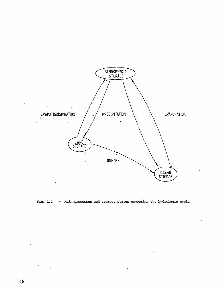
The hydrologie cycle is an expression of the ideas that the quantity of water on earth is constant and that this quantity of water takes part in a number of natural processes which transfer* it from one state of storage to another. The primary states of storage are those in the oceans, in ice, in the atmosphere and on or in the land. The main transfer processes are evaporation, precipitation and runoff (Figure 1.1).
Early in their schooling, people are taught about the basic concepts of evaporation, E, (from sea and bare land) and évapotranspiration, ET, (from vegetated land) under the sun's action on these surfaces as well as of precipitation, P, from the clouds due to the effect of water vapour condensation in atmosphere. This domain of "hydrometeorology" involves the atmosphere and is limited to the earth's surface.
From there, the various paths followed by the precipitated water reaching the oceans or returning to the atmosphere are complex and not easily separated. Indeed, it is sometimes hard to visualise the various parts; for example the runoff, R, which feeds the river and the infiltration, I, covering the behaviour of the part of the water infiltrating the soil profile.
15
EVAPOTRANSPIRATION EVAPORATION
Fig. 1.1 - Main processes and storage states composing the hydrologie cycle
16

The runoff process is the domain of the "Surface Hydrology" and the infiltration process is that of "Agrohydrology".
The soil is a temporary water reservoir from which the plants feed. The water of the soil reservoir that is not returned back to the atmosphere by évapotranspiration nor retained in the soil by capillary forces percolates through the subsoil to the aquifers. These are groundwater reservoirs where water fills up all the cavities and pores within the geological formations. This is the domain of "Hydrogeology".
In an unconfined aquifer the level of the water surface is called the "piezometric level". In a confined aquifer the piezometric level is the sum of pressure head and water elevation. Where the piezometric level is the same as that of the ground or higher, a "spring" appears and where it is in contact with a river, groundwater flow contributes to the "base flow" of the river on its way to the sea.
As fresh water is continuously replenished in the land phase of the hydrologie cycle, man not only catches it, either at the earth's surface in springs, rivers, ponds, lakes and man-made reservoirs or below the surface in aquifers with the help of pumps, but also returns most of what he uses back as waste water either in the rivers, in the ground or in the sea. The bypassing of the natural cycle created by agricultural, industrial and domestic activities has generated two major water resources problems of supply and pollution. The complexity of these problems results from the conflicting combinations of the quantity and the quality of the water needs and uses as functions of time and space.
The first and most important quality of water resources is their quantity. Quantitative aspects of water resources have traditionally formed the basis of water resources education. This publication concerns only the experimental facilities for the study of these quantitative aspects. A book on water quality surveys has already been published by UNESCO and WHO in 1978.
The total amount of water in vapour, liquid and solid phases is essentially constant around the earth. Most of the water is in the ocean, but water resources available to man are unequally distributed in time and space over the land surfaces.
With the symbols introduced above, a water balance equation for a given catchment and during a given period of time can be presented as follows:
• P = ET + R + I +_ AS (1.1)
where AS represents with the plus sign the increase of storage and with the minus sign the loss of storage in the catchment.
The terms of this equation are commonly expressed in units of water depth and must be determined with maximum accuracy. The difficulties encountered with this equation are due to the fact that the methods used for the determination of the terms in it seldom involve the same time period and that it often occurs that more than one term remains unknown. Besides, direct measurements are not always possible, so the terms of the equation are often estimates obtained through calculations of other data.
Another approach showing the relations between the flux'(or process) functions and the natural water reservoirs of a region for the water cycle over land surfaces is illustrated in Figure 1.2. This approach allows for the explication of the variations of the water storage during a given period of time At in the hydrologie cycle according to the following equation:
ASm = AS, + AS„ + AS„ + AS "+AS„ ' (1.2) T A P S G R
where AS is the total water storage variation, and
AS is the storage variation of the soil surface subjected to the flux functions P, E, R, I
AS is the storage variation of the soil profile subjected to the flux functions E, I, L, D
AS is the storage variation in the subsoil subjected to the flux functions D and A
AS is the storage variation in the groundwater reservoirs subjected to the flux functions A, B, W
AS is the storage variation in the rivers and lakes subjected to the flux functions R, L, B, Q
This change in water storage is related to the flux functions by
AST = P - (E + Q + W) (1.3)
17

FLUX FUNCTIONS: E. EVAPOTRANSPIRATION P. PRECIPITATION I. INFILTRATION R. RAPID RUNOFF L. SLOW RUNOFF D.DRAINAGE OF THE SOIL PROFILE RESERVOIR A. AQUIFER INPUT FLUX B.BASE FLOW W.WATER LOSSES FROM THE AQUIFER Q.RIVER DISCHARGE
2 - The five reservoirs in the land phase of the hydrologie cycle and their related flux functions
The time period At to be considered still raises problems due to the fact that the hydrological terms (P, E, R, I, L, D, A, B, W and Q) which link the water reservoirs depend upon natural phenomena involving different time scales, e.g., from minutes for P to months and years for W (De Backer, 1978).
From Figure 1.2., it can also be seen that over a long time period, for which AS equals zero, the total flow discharge of a river Q is given by the sum of the rapid runoff R, delayed runoff L, and the base flow B
Q = R + L + B (1.4)
It should be pointed out that the precipitation P and the flow discharge Q are the only two hydrological terms commonly measured.
It is tempting to use the simple Rainfall-Runoff relationship frequently considered in modelling when one realizes the intricacy of the natural ways followed by water. Such simple models are based on the idea that surface runoff R and delayed runoff L contribute most to the total flow discharge. However, studies based on measurements show that the base flow B can contribute up to two-thirds of the total flow discharge Q of the river over a year.
Fortunately, the terms in Equation (1.2) can be studied separately according to the specific water resources objectives and could possibly be measured by means of actual, advanced or new methodologies and technologies.
These very schematic and brief considerations about the hydrologie cycle and its relations with water resources emphasize the need for more hydrological data of different types and more studies. This implies in turn the development of more experimental facilities for water resources education.
1.1.2. Study of Hydraulics and Hydrological Processes
Today it appears that most of the plentiful catchments have been tapped or no longer meet our needs and that waste water pollutes our environment. We thus have to find new ways to supply more water and to manage our effluents. Hydraulics is used to solve problems with well-defined boundary conditions, but hydrological processes are considered when natural conditions must be taken into account. Hydrological study is thus used for such projects as the development of new catchments, artificial recharge of aquifers, waste water disposal, etc. One has to determine the location and the size of watersheds large enough to fill new reservoirs and supply the amount of water required, of wells either for groundwater supply or for artificial recharge or for wastewater disposal by selecting the adequate aquifers, of infiltration sites for artificial recharge or waste water disposal, etc. All these determinations ' imply knowledge of the hydrological processes involved in the water cycle as they are affected by man's activities. With the development of multipurpose water works, the complexity of the problems and the amount of information necessary to study the projects increase drastically. What was some time ago a one-man project now becomes a team project involving many more' specialized people.
A long historical series of hydraulic and hydrological data is needed before the project starts, and after the completion of the entire work more data must be collected regularly in order to follow its behaviour and to insure its maintenance as well as to verify the various hypotheses and models made during the establishment of the project. The improvement of our knowledge about hydraulics and hydrological processes depends upon these continuing studies through guided experience.
1.1.3. Role in the Educational Process
A harmony in the teaching of geoscientific knowledge is established through books, laboratory work and field trips. In natural sciences, the process is basically descriptive. In engineering sciences, a high level of abstraction is necessary in order to define the system in which a given phenomenon occurs.
While natural phenomena and mechanisms are often not yet fully understood, engineers have physical laws and technical tools which allow them to work with systems well defined by boundary conditions. It is then obvious that the transfer of knowledge through demonstrations and practice are far better developed in engineering than in natural sciences and experimental facilities in engineering education are readily available where technological development requires experimental skill due to the degree of sophistication. Yet, experimental experience plays a more important role in natural sciences because the amount of knowledge still to be acquired is overwhelmingly greater than in engineering sciences.
Water resources sciences proceed with the combination of both types of experiences; the sophistication found in engineering and the understanding of hydrological processes which belong to natural sciences. The part devoted to experimental experience for water resources
19

education is thus of prime importance and must be developed at all levels of education through-exercises, laboratory, field trips and reports.
1.2. THE NECESSITY OF EXPERIMENTAL PRACTICE
In addition to the motivation described above about the importance of experimental experience in water resources education, experimental practice is a necessity in the understanding of theory, in the training of practitioners, in the gathering of data and its improvement for water resources design needs and for operation and management of water resources projects.
1.2.1. Understanding of Theory
Deep in the nature of man, curiosity acts as one of life's driving forces: the desire to know. Several steps mixed with reasoning are involved in the process of acquiring knowledge. Observation and description, analysis and interpretation, separation and relation, induction and deduction, experimentation and verification all converge with intuition toward principles or laws. Together with rules, and conventions they form the basis of what is called theory. It is transmitted from generation to 'generation, and whenever necessary, modified, improved or rejected.
No matter how ambitious one man can be, he will never be able to rediscover in one life all the heritage of knowledge. In his field of activities he will pick up whatever is .useful to him. Even such selection is time consuming and therefore educational programs have been set up, for example, by UNESCO in the Technical Papers in Hydrology, N° 10 and N° 13.
In water resources education, the theoretical part involves the principles, laws, rules and conventions of hydraulics and hydrology. By means of carefully selected demonstrations and experiments, the students can go concisely through the steps that lead to their establishment and so satisfy their curiosity by rediscovering the theory. They should also understand the field of application and limitations of the theory. Through experience, they can also develop inventiveness and appreciate the quality of data.
Another very important reason for experimental practice is the improvement of theory. Many applications of theory are made possible by analogy between some phenomena. Theory also gives rise to models either physical, analog or digital (UNESCO, Technical Paper in Hydrology, N° 11). Practical experience with models helps greatly in understanding not only the theory on which they are based and the phenomena-simulated by the models, but also their limitations in giving a true picture of the phenomena.
Both laboratory and field facilities are described for hydraulics and hydrology in Chapters 3 and 4.
1.2.2. Training of Practitioners
A practitioner is one who practices a. profession. Do such professions as those of hydraulician and hydrologist exist? Yes, despite the fact that the domains of knowledge required to be fully qualified are so large that even if one could understand all the theories, it is impossible for him to put them all in practice. Therefore, one speaks usually of technicians, engineers or researchers in some specialized fields of hydraulics or of hydrology. Thus there exist some training levels that depend mostly upon the amount of theory which -the practitioner wants or is able to understand as well as his ability to put them into practice. All educational programs include experimental practice for these reasons. This is particularly true in hydraulics and in hydrology because the sophistication of most theories and equipment requires a great deal of intellectual as well as manual ability, not only in the laboratories but also in the field (WMO, Guide to Hydrological Practices, 3rd Edition, 1974).
The practitioner cannot always repeat exactly the same experiment, especially in natural phenomena, and must constantly demonstrate the reliability of his results. Moreover, the water resources managerial decision on which often- depends the well being of the population and/or the preservation of the environment depends, in turn, on the conclusions drawn by the practitioner.
The teaching of experimental practice in water resources obviously does not include all the situations .which the practitioner will encounter but should give him the background necessary to adapt his knowledge to real situations. To be a,good practitioner implies more than repeating exactly what he has learned at school. Self teaching and self training characterise the efficient practitioner. However diligent in his profession, he cannot be aware of all the new developments that occur in this: growing science of water resources. Continuing education programs with organized field trips and laboratory visits are presented in each specialisation and contribute largely to the training of the active practitioner.
20

1.2.3. The Gathering of Data and its Improvement for Water Resources Design Needs
Water is in perpetual movement. The only way to evaluate the amount of water available for a given purpose is to measure regularly and/or predict the water fluxes that cross at any moment the input and output boundaries, first according to natural conditions, second within the design structures, and third according to the disturbed natural conditions. The comparison between the undisturbed condition and the new situations shows the feasibility of the design to meet the required needs and to define the consequences that the future design structures will bring to the local water balance. Most water problems occur because these precautions are not taken rigorously.
Hydrological measurements (see Chapter 4) might seem expensive at a time when water resources are not yet needed. However, prediction is impossible without a historical recording of hydrological measurements. The longer the record, the better the prediction.
Hydraulics measurements (see Chapter 3) are usually taken only when a model of some • structure is required. The running and/or maintenance of such models might involve a period of time exceeding the time of the study in order to verify the results obtained by the model with those of the prototype.
Special procedures must be set in order to give enough reliability to the measurements before any treatment, interpretation and use., Chapter 2 is devoted to these considerations. The results of measurements are therefore only part of all the data needed for water resources design (see Section 1.3).
Data gathering is expected to be a well organised activity in which a great deal of responsibility is involved. Many users of these data need them for various purposes either directly related to the concerned water resources design or for later development of activities involving the same water resources (see Section 1.2.4).
Educational programs in water resources must give the student an opportunity not only to perform some measurements but also to present the data in a way that will allow him and others to use them later on. This presentation varies from one service to the other but all information must be at hand to guarantee the meaning of the data. As it was mentioned above, water resources design needs might develop anywhere and at any moment. This means that water resources data gathering over long periods of time is of utmost importance everywhere. This . might have seemed impossible some years ago but since the development of remote sensing technology water resources investigation can be made almost anywhere provided enough ground truth data are available to establish the relationship with the remote sensed data. Today, the amount of information obtained from remote sensing by far outnumbers the availability of corresponding ground truth information. Experimental practice in the gathering of data in these new fields will therefore lead to meeting the needs required in water resources designs of water works.
1.2.4. The Gathering of Data for Operation and Management of Water Resources Projects
The development of water resources projects requires several years and as many data as possible. The data should cover not only periods before the projects are initiated but also complementary data during development. Once a project has been executed its operation requires the gathering of data necessary to meet requirements of operation. Sophisticated equipment is developed to guarantee measurements on a "real time" basis. At such levels of operation the computer is a necessity. The control of all the elements of the project can thus be maintained and their behaviour followed according to the predictions as well as to the models developed during the study of the project. Modifications can then be brought forth and accidents prevented.
Students in water resources education also should be aware of data gathering expressly for water resources management. These data involve not only:all the data necessary for water resources design and project elaboration and operation but also data pertaining to the eval- • uation and prediction of water resources needs within the project, and even those of other projects if the resources are not completely available within the project.
As the level at which one studies water resources increases, the degree of complexity of data gathering increases along with the degree of reliability of the measurements. This emphasizes the importance of experimental experience in the training at all levels in water resources. Special attention should'be drawn to the use of models in the operation and the management of water resources projects:
Data gathering must not only be well organized but also well understood by all parties. On one side, those who perform the measurements and prepare the data necessary for the running of the models must receive a general outline of the models and have a good understanding of the scope of the project. The instructor's readiness to learn and answer the students' questions about situations where "their" data are used contributes highly to improve their motivation for the work, their integration into the project and, as a consequence, the reliability of the
21
data. On the other side, those who elaborate and/or work with the models/ besides the general scope of the project, need training in measurements in order to understand both the field conditions and especially the work as well as the limits involved in obtaining the data.
A common language thus develops among all partners of the project and leads to a mutual understanding between those who produce and those who use the data, and therefore to the efficiency of operation and management of the project.
1.3. WATER RESOURCES DATA
The collection of data is essential to analysis, design and management of water resources projects. In this section the nature of data for water resources development uses is discussed, along with the purpose and usefulness of data.
1.3.1. Definition
Water resources data are understood to be numerical values of the measurements of those hydrological and meteorological phenomena which change with time and which can be measured directly or by a direct consequence of their occurrence, and other, more general information which does not change with time, needed in water resources development. Hydrological and meteorological data result from the measurement of physical phenomena such as velocity, discharge, groundwater levels, sediment carried by stream flow, evaporation quantities, precipitation, wind speed, temperature, specific humidity, cloud cover and insolation. Some data result from simple, single measurements, such as wind speed, water stage, precipitation, stream flow velocity at a point and groundwater levels. Other data.are derived from one or more simple measurements, such as stream discharge, évapotranspiration, groundwater flow, and dewpoint. In any case, all data of this sort are directly applicable to water resources management.
Some data are records of time-varying phenomena; examples are wind speed, precipitation and discharge. Others are records of phenomena which are relatively constant with time and normally do not need repeated measurements to establish a time function. Examples of non-varying information are catchment size, stream slope and soil structure. These data are often available from sources other than measurement by the water resources data gathering team. They can be obtained from topographic maps, soil survey maps and the like.
Some data are used in water resources work but are not essentially hydrological in nature. Such factors as land use, demographic figures and water requirements for industry are examples. Collection of data of this sort is outside the scope of this work. This monograph is concerned only with measurements of a hydrological and meteorological nature.
1.3.2. Purpose of Data
The collection of data serves a primary purpose in water resources management and development; as an information source for analysis, design and operation of facilities. Often measurement and data collection are directed to a specific purpose or project, and have utility only to meet that particular need. Despite the limited utility however, this purpose of data is, of course, extremely important. Data collection can be performed for purposes other than design, for example, a measurement and data collection network might be developed for a flood-forecasting program. . .
. Data are gathered and stored in order to build up an information base for future, unspecified uses. This may be the most important function of water resources data collection. It has already been noted that the planning and design of water resources systems depends heavily on an inventory of accurate and relevant data. These data are very often time dependent, so historical records are often essential for. many projects. In many cases the value of the information gained from the data is a function of the length of record. For example, stream flow records provide more accurate estimates and permit more types of analysis if the records are long and.unbroken. It is apparent that data collection networks must be designed with the idea that future uses may have needs presently unrecognized, that long, continuous records may be necessary, and that fairly broad areal coverage by data is desirable.
Obviously, it is extremely difficult to plan data collection networks to meet future, unspecified needs for the data. Nevertheless, the difficulty does not lessen the importance of this purpose, but rather makes it imperative that careful, serious work be done in collecting and preparing data for these kinds of data bases. The opportunity to take the measurements and record the data will pass and will not be present in the future. It is better to err on the side of taking more data than to find that insufficient data were taken.
22

1.3.3. Quality of Data
Data quality can refer to several aspects of data. One feature of data quality is continuity. Continuity is that unique property that time series of measurements have. The quality of data which describes time-dependent variables is impaired if there are breaks or gaps in the record. Records can be of high quality in other ways, but if they are not continuous the data may be useless for many purposes.
Data should also be consistent in the statistical sense, they should be a record of measurements of variables of the same population. Sometimes this feature of data is destroyed by moving a gauge,, or by changing environmental factors in the area of the measuring site. It is quite possible, of course, that this aspect of data is outside of the control of the manager of the data collection scheme. It is therefore important to place on record information, other than the data recorded, that will give future users an evaluation of the extent of changes in environmental factors. Consistency of data includes consistency of its precision and accuracy.
The collection of data should be undertaken with a good understanding of the requirement of completeness. Data should be complete, sufficient to the purpose, whether the purpose is operation and management of a-project or economic design of a major water resources system. Completeness can have a statistical context, but the meaning goes beyond that to meeting the technical and engineering needs. The burden of designing an information and data system for future needs rests heavily on the data gathering office and its administrators.
1.4. THE OBJECTIVES OF THE MONOGRAPH
This monograph is intended as a guide to the teacher of water resources technicians and university students, to aid the teacher in establishing physical facilities which can introduce the learner to methods, techniques and instruments used in water resources management and assessment. It is not intended to be an exhaustive list of equipment and their descriptions or a laboratory manual, rather it is to be a form of rough blueprint to aid in the planning of the laboratory experience and to aid the teacher in the selection of equipment and experiments. The facilities described are limited to hydrological and hydraulic aspects of water resources design and management. Specifically excluded are matters directly related to water quality.
1.4.1. Scope of Hydraulics and Hydrology Facilities
The facilities described in this monograph are classified into two types, hydraulic and hydrological. The hydraulic facilities are representative of a quite traditional hydraulic or fluid mechanics laboratory. The activities in the hydraulic facilities are intended to present demonstrations and experiments that illustrate and amplify on principles of fluid mechanics. Experiments requiring calibration and use of standard laboratory instruments are envisioned along with operation of equipment such as pumps, valves, gates, etc. Descriptions of basic and desirable equipment and instruments are provided, along with some suggestions on sizes and capabilities. Emphasis is given to equipment found in hydraulics laboratories, such as open-channel flumes, both with and without sediment flows.
Hydrological teaching facilities is a term used to describe equipment and instruments—and places to use them—that are normally associated with field work in hydrology. The placé of instruments for measuring meteorological variables, precipitation, evaporation, stream velocity and stage, discharge and soil moisture is described. Specialised equipment and its need is described—some examples are groundwater analogies, photographic interpretation and data handling equipment. A section is devoted to description of outdoor, or field work, and some attention is paid to the details of that aspect of hydrological facilities, an area that the authors believe is extremely important.
1.4.2. . Educational Level of Facilities
The water resources experts who would be the subject of training given in the facilities described here are intended to be senior-level technicians and university students. Senior-level technicians can be expected to be field party chiefs or others in responsible charge of data collection in the field and storage of data. Of course, it is apparent that such technicians need good training and -experience in measurement techniques". In all the teaching facilities described here there are devices for measuring properties of fluids and materials and calibration equipment as well as instruments and equipment more specifically directed to hydraulics and hydrology. This has been done because the authors believe that senior technicians need a practical understanding of basic fluid flow concepts, so that the senior technician can make good judgements when faced with new experiences in the field. The senior technician must be trained to be able to manage without close supervision. University students, too, need training in measurement techniques, and although their expertise in the use
23

of instruments and techniques need not be as high as that of senior technicians, their understanding of the purpose, techniques, and strengths and limitations of measurements is essential. Obviously, university students of engineering in hydraulics, hydrology and water resources need a sound foundation in the properties of water and in the basic concepts of fluid flow, as well as some understanding of practical or applied hydraulics and hydrology. In the authors' thinking, the needs of senior practitioners and university students are parallel enough to permit the use of common facilities. The teacher will have to determine the specific direction of experiments and projects for the two groups. The facilities described in this monograph are not intended for research per se, but it is recognised that some of the equipment could be used for basic or applied research. Normally, research activities require considerably more free space and flexibility of space and equipment than is proposed to the teacher in this monograph.
1.4.3. Suggestions for Teachers
The chapters that follow have been planned to be suggestions for teachers that represent, in the authors' opinion, a minimum facility for training in the measurement and collecting of water resources data. These are recommendations for equipment and instruments for both hydraulic and hydrological teaching facilities, and descriptions of possible physical arrangements. Also included are suggestions for outdoor facilities and activities. The authors believe experience in realistic situations to be an essential part of the training program for water resources data gathering practitioners.
The individual teacher developing and using a water resources training facility will likely find it necessary to modify the recommendations and suggestions found in this monograph. Restrictions imposed by funding, class size, climate, level of trainee, objectives of training program, etc., are all factors which must be considered, and can possibly lead to differences in selection of alternatives in facility size and equipment. Nevertheless, this monograph should provide a ready source of information to aid the training of water resources practitioners.
24

2. General concepts of measurements
2.1. GENERAL
In this chapter definitions and meanings of some of the terms used are established, and the general importance of measurement is discussed, along with its relationship to data and variables. The treatment is not intended to be a guide to statistical and probabilistic foundations for designing a program of experimental measurement, rather it is planned to provide a general background in terminology and to be a reminder of some of the important considerations in data collections.
2.1.1. Definition and Characteristics of Measurements; Dimensions and Units
Measurement is the name given to the value or amount of length, capacity, velocity, or some other property of a quantifiable, physical entity. Measurement is obtained through the act of measuring. The values of the measurement of the physical entity serve to describe it. Measurements are expressed by the concepts of dimensions and units.
Dimensions are the names given to those singular attributes of physical entities that describe their relation to other physical entities. Examples of dimensions are the qualities of mass, length, time, temperature and electrical charge. Many of those singular attributes are recognized in applied fluid mechanics and hydrology. Some, such as temperature, are important in defining properties of the fluid, like density and viscosity. Other attributes are quite directly part of the phenomena of fluid flow. This is particularly true of mass, length and time. For example, velocity and acceleration can.be expressed as combinations of length and time, and pressure is a combination of mass,^ length and time. In fluid mechanics practice force can be expressed through the empirical relationship of Newton's First Law, force equals mass times acceleration, where acceleration is expressed dimensionally as length divided by time squared. It should be stressed that because dimensions are descriptions of the singular attributes they cannot be reduced further, although they can be stated alternatively through essentially empirical relationships as described above...
Units are arbitrary measures of dimensions and combinations of dimensions because measurements are essentially artificial and arbitrary. Although the measurement is artificial and the unit is arbitrary, the properties of the physical entity-being measured is neither artificial nor arbitrary. For example, the area of a lake is a physical reality regardless of the dimensions and units used to describe it. The dimension of area is usually expressed as length squared. The units of area are arbitrary, however; they can be hectares, square metres., etc.' Similarly, the time interval between discharge measurements can be expressed in minutes, hours, days, etc., and although our concept of time is that it is physically real, the. unit is arbitrary even though it may be based on an observation of a physical phenomenon (the rotation of the earth).
There are many systems of units, but the metric Systeme International (SI) and the English are probably the most widely used. The Systeme International is the only recommended one. All systems have been developed for many years and contain units that are constructed to describe measurements of combinations of dimensions. For example, discharge can be expressed in cubic metres per second, but it is a combination of the dimensions of length cubed divided by time. The relationship of units to dimensions is valuable in conversion from one system of units to another.
25

2.1.2. Simple and Derived Measurements
Simple measurements are those taken of entities or the phenomena directly, for example, flow velocity or rainfall depth. Many water- resources data are records of measurements of this kind. The data representing these measurements are very important since they are the bases for a great part of the water resources information.
Derived measurements is the name given to values of variables which are computed from other measurements, but are still values representing a fundamental variable. For example, infiltration is estimated by observing rainfall and runoff, and essentially taking the difference. Similarly, discharge in a stream can be determined by measuring velocity at a number of points and combining these with measurements of the area of the cross-section of flow.
2.2. ACCURACY
Accuracy is a description of the closeness of a measurement to the true value of a • physical entity. The concepts of accuracy of data are important in any data collection effort. In water resources data there are problems of matching the accuracy of one set of data to another. Involved in the definition of accuracy are precision of instruments and problems of systematic and casual errors. In this section the topics named above are treated in a general fashion, and some aspects peculiar to the accuracy of water resources data are discussed.
2.2.1. Precision of Instruments
Precision is the ability to discriminate between different values of the same variable. It largely is a function of the instrument used. As an example of instrument precision, some rain gauges are precise to 0.1 mm. The capabilities of instruments used in water resources data collection are generally well known, and information on the precision of most is generally available from the manufacturer. When planning data collection networks and management practices it is essential that consideration of the precision of the instruments be included. Such considerations can limit the general accuracy of the data being collected, or it can affect the selection of the instruments or the method of data reduction.
2.2.2. Sources of Error
Errors lead to an erosion of the accuracy of data. The operator or the instrument can contribute to the magnitude of errors which may be casual errors or systematic errors. Casual errors are relatively small positive or negative random variations from the true value due to various sources. They are usually described in statistical terms. Systematic errors consistently tend to either overestimate or underestimate the measurement. For example, a staff gauge may have an erroneous reference elevation, or a current meter may have a faulty bearing, causing drag which slows down the propeller's revolution count. Some systematic errors can be corrected if the nature of the change in the data can be ascertained. Sometimes systematic errors are present in data which are used in turn for further computation, or which are reduced in some other way, and the reduced data are all that is kept in archives. In such a case the reduced data are in error, and the correction for systematic error would have to go back to the data where the error was introduced.
Errors due to the operator's.mistakes sometimes enter into data. These are random in nature and may be sometimes positive and sometimes negative. They typically occur through human error; misreading a gauge, or writing down an incorrect number. It is also possible that a malfunctioning instrument can introduce these errors. It is virtually impossible to correct such errors unless they are noticed at the -time of measurement. Since these errors generally affect only one item of data, they are not subject to correction as are systematic errors.
2.2.3. Total Accuracy
The total accuracy is a function of the combination of instrument precision, casual and systematic errors. Instrument precision can be expressed in a statistical fashion, as a unit of precision plus or minus a number. That number usually is the standard deviation, which, if a normal distribution describes the instrument's Variation in precision, means that approximately 68 percent of the measurements made will be within the range. Of course, the magnitude of systematic errors and mistakes cannot be expressed in a probabilistic manner, although their occurrence can be anticipated in a.statistical sense.
The aspect of matching the accuracy of water resources measurement and data gathering to their purpose is extremely important. It is essential to consider the ways in which the data are to be used, so that the accuracy of the data is appropriate to their purpose. If unnecessary accuracy is attained, the cost of acquiring data will be higher than necessary, and
26

alternative uses for the money allocated to data collection will be lost. If the accuracy of the data is insufficient, the loss of information can never be recovered in many cases, and further losses may be incurred through poor design, faulty operation or some other, similar consequence of poor information. However, since the future use of water resources data is not known, it is considered better to err by having too much accuracy rather than too little. The senior water resources practitioner should be aware of the problem of matching accuracy, and he should understand the role the practitioner plays in matching objectives and data gathering.
Generally speaking, the accuracy of measurement should be that of the precision of the instrument. Only through techniques such as replication can accuracy greater than instrument precision be attained. However, since variables measured in water resources work are nearly always time varying, space varying or both, replication of many commonly made measurements is impossible. A measurement of less precision than that of the instrument may take just as long to perform, and so it will not represent a cost saving. The problem of matching the need for accuracy in data collection to the purpose is more severe in water resources applications since the future use is often unknown, and the requirement of the level of accuracy cannot be determined. In this regard, it is important for.the water resources practitioner to record his estimates of accuracy: of the data he collects so a future user can make an assessment of its importance.
2.2.4. Temporal and Spatial Variability of Water Resources Data
Most useful water resources information is highly variable in space and time. As an example, rainfall rates vary widely during a storm, as is seen from looking at a trace of a recording rain gage. Rainfall distribution varies widely spatially, too. Similar examples can be given of nearly all water resources variables. The planners and managers of a data collection system must be aware of this variability and take it into account. The selection of locations for measurements and the sampling intervals must be carefully considered in relation to the purpose of the measurement. There are approaches to optimization of gauging networks that have been successfully applied, and offer valuable examples of the optimization technique. The use of "benchmark" stations, which are stations that are established for acquiring long-term records, and a program to correlate short-term records at other nearby stations might prove to be valuable and productive, and better than an attempt to establish a very large number of long-term stations.
Experimental basins are often used to help establish the nature of hydrological regimes, so that the knowledge .of the regimes can be extended to operational use and for development of water resources generally. The data collection networks for experimental basins will be much more extensive than those networks intended to establish a general data base for water resources systems. Too, the experimental basins will often have special requirements that need to be met. Much like benchmark stations, special care must be taken in the selection, location and operation of the data collection system on these experimental basins. The accuracy expected for measurements taken in experimental basins is higher than that usually attainable in field measurements.
2.3. WATER RESOURCES VARIABLES
Measurements and data collection and storage are means to obtain values of water resources variables. The variables themselves are the things of interest and importance in the analysis, design and operation of water resources systems and in the science of hydrology. The hydro-logic cycle is studied through measurements which provide data. These data in turn serve to describe the water.resources variables, and finally our understanding of the hydrologie cycle is increased by the study of the nature of the variables.
2.3.1. The Nature of Water Resources Variables
Most water resources variables can be considered state variables of a dynamic system. State variables are called that because they describe the state of the system at any particular time. The name comes from the literature of dynamic programming. The system is usually the catchment or some part of it, and the state variables describe its conditions. Since the system is dynamic, state variables are time dependent. In hydrological systems these state variables also have a space dependency. The time and space dependency is, of course, the reason for on-going data collections of water resources variable measurement. The very nature of time and space dependency is what the hydrologist and water resources analyst wants to determine. State variables may be exemplified by precipitation, stream discharge, soil moisture and groundwater levels.
Related-to state variables are parameters, those entities that describe the catchment itself. Examples might be stream length, basin area and a trace of the watershed. While state
27

variables are functions of time and space, parameters are considered to be invariant in analysis. Of course some, if not all, parameters change with time when time is measured on a very long scale, and sometimes man's activities change parameters through construction (a dredging and channel straightening project) or through land use. It is useful to think of water resources data collection in this sense because it parallels the newer ways of describing the response of catchments through numerical simulation.
One can also describe the characteristics of water resources variables in the same general way that measurements were described in Section 2.1.1., in terms of their dimensions and units. As with the measurements, some state variables and parameters have simple dimensional description, others are expressed as combinations of dimensions. Units, of course, are arbitrary and conversion from one system of units to another is a simple process.
2.3.2. Measurements and Instruments for Water Resources Variables •
Instruments used to measure water resources variables are as varied as the variables themselves. Some instruments are available to measure the state variables directly. In fact, the concept of the utility of a specific variable and the development of an instrument to measure it are parallel and mutually dependent. Other instruments measure variables from which the water resources variables of interest are computed. Many instruments are standard devices in engineering and science practice. Devices for measuring length, time, mass and temperature, for example are not particularly unique to the water resources field. Other instruments are unique to hydrology, hydraulics and water resources. This list would include apparatus for measuring evaporation, precipitation and soil moisture content.
New instruments and techniques are constantly being introduced for the measurement of-water resources variables. Examples are radar for measurement of precipitation, radioactive tracers for diffusion studies, ultrasound for flow, etc. One can expect these new instruments to trigger the development of new ideas about water resources variables and their management.
2.4. DATA HANDLING
Central to the problem of producing useful data for water resources planning, management and operation is the handling of the data after the measurements are taken. A program of variable measurement and data collection is not complete unless care is given to the handling and storage of the data. The quality of the data handling and storage should be at least equivalent to the quality of measurement.
2.4.1. Data Collecting, Reliability and Reduction
Data collection should be systematic, with methods of data handling standardized as is the measurement process. Data handling includes transmission, reduction, recording, storage, and recovery, and each operation should be given attention.
Transmission of data is sometimes the simple act of delivering a notebook, but it can also include electronic transmission of signals in some way. Remote rain and snow gauges have been in common use for some time, as an example, and the information that they acquire is often sent by wire. Transmission of data can also include delivery of information to a user from the storage location or archives. Sometimes that delivery can be through electronic means. The data transmitted can be in the form of printed or written tables but it can also be on magnetic tapes or punched cards.
Data reduction refers to the transformation of the values of the measurements themselves to the values to be stored; which are the variables of interest. Reduction is sometimes done by hand, but it can be done by a computer. Care must be exercised in the reduction of data', because systematic and casual errors can arise here as easily as they do in the field. The accuracy of the information after reduction should not be less than that of the data brought in for reduction. In some cases, again using rain gauges as an example, the sensor can transmit data electronically to a central computer where the measurements are transformed or reduced to the desired variable form and then stored for future use by the computer. In such instances, no intervention by man is necessary in the flow of information. . • •
Recording,, storage and recovery of data refer to the processes of creating and using a data bank. Data are stored in the data bank; those stored data are called a data base. As implied earlier, a data bank can be a computer memory device, with electronic connections to the sensors of measurements, or terminals for entering data, and with connections to users through electronic displays, printers or some other device. Data banks can be less elaborate, too, and may simply be files, decks of punched cards, magnetic tapes, or similar storage equipment.
Whatever methods of data handling are used, the same level of care in development and operation of them should be exercised as done in the collection of measurement data. The
28

accessibility and reliability of the results of a data collection program is as important as any other factor in water resources development.
2.4.2. Verification and Correlation of Measurements
Independent checks of the data collected in field measurements make it possible to verify their correctness. This can be done in several ways, one of which is repetition of the measurement in the field, sometimes with a different instrument. For some time varying measurements it will not be possible to replicate, of course. In some cases an additional measurement may be too costly, or otherwise impossible. Often, verification in a rough way can be achieved in the data reduction stage through comparisons. Values which are significantly different from those of previously taken measurements may be suspected of error.
Several types of correlation, consistency and statistical analyses are available as checks on the correctness of data. In some cases it may be possible to establish the correctness of the data, or rather the lack of gross errors and mistakes, by computing the correlation coefficients between the observed data and other data collected at the same site or at nearby sites. Techniques such as double mass curves may be useful in this respect. Some stochastic variables may be checked by computing auto-correlation coefficients of the series of values as they are being collected or reduced.
29

3. Hydraulics laboratories
3.1. GENERAL
As Stelczer writes in the 1972 UNESCO publication, "Teaching Aids in Hydrology", (Technical Paper in Hydrology, N° 11): "For a proper understanding of hydrological phenomena, an understanding of the related hydraulics and the relevant relationships are essential. No up-to-date teaching of hydraulics is possible without demonstrating the hydraulic processes, and it is inevitably necessary for the students not only to observe the phenomena but to perform measurements personally in order to determine the characteristic values, get an idea of the nature of relationships and discern the roles of variables."
Experimental techniques in fluid mechanics have been used since the earliest efforts in this science, but the hydraulics laboratory as an educational or research tool was not developed until the introduction of physical models for the study of hydraulic problems. Only at the beginning of this century, after the early research work on hydraulic models, has the hydraulics laboratory become universally required for experimental research and education.
3.1.1. The Purpose of Experimental Hydraulics Teaching j • -
In many disciplines, rational theories are sufficient to account for the various phenomena which comprise their fields. In fluid mechanics, too, the application of the conservation principle to mass, energy and momentum together with the fluid state equation should be enough to solve any problem, taking proper account of the boundary conditions of the case under study. However, even within the framework of the relatively simple Newtonian mechanics, where the general equations that describe fluid movement are well known, many problems still require experimental treatment. This is mainly due to approximations in describing the boundary conditions or simplifications introduced in the equations.
Considering the importance of experimentation in the field of hydraulics it is thus imperative to introduce it during the educational stages of professionals and technicians. In addition to its role in solving real problems, the experimental observation permits the student to clearly understand the fundamental principles which cannot be easily explained by the teacher. The student will be able to come into contact with the fundamental laws and verify their validity.
It is possible to demonstrate the fundamental laws through experiments using simple equipment, which can be constructed locally. A complex and very precise system is not always the most suitable for educational purposes. The student must be able to observe and understand all the equipment which is used in the experiment and at the same time, he must keep in mind the purpose of the experiment.
The hydraulics laboratory facilities should offer the possibility of performing classic experiments, and the demonstration of fundamental laws. Generally, the hydraulics laboratory should have facilities for scientific and technological research in addition to those specifically for educational purposes.
The dimensions of the laboratory will depend on educational requirements, the available means, and the laboratory's expected use in research. Naturally, the design of the laboratory is an important task because it will impose conditions on the equipment to be installed, it will also determine its characteristics in relation to the aim, whether educational only, or educational and basic and/or technological research. Generally it will be worthwhile to combine the purposes, but too many technological uses will compete with the educational
31

purposes. However, limited applied research can be recommended from the educational point of view.
3.1.2. Classification of Laboratory Equipment and Facilities
The experimental equipment of the hydraulics laboratory may be classified according to its objective in three groups: equipment for measuring physical properties of the fluid and characteristics of the flow, classroom demonstration facilities and laboratory facilities.
The first group comprises conventional instruments, generally manufactured, which are usually kept in a storeroom, and taken out only for performing experiments. Once the experiments are finished, the instruments are put away in the store after routine maintenance.
Classroom equipment is specifically designed to demonstrate the fundamental laws and criteria of hydraulics. Examples of such equipment are devices for the energy law and the momentum law demonstration, the Reynolds experiment, a capillary rise demonstration, and a flume for open-channel flow demonstration. The students' access to this equipment is usually restricted, and the teacher will usually perform these demonstrations.
The equipment which is classified as laboratory facilities allows the teacher to set practical exercises where students have to conduct measurements and interpret results. The purpose of these laboratory facilities, in addition to providing training in the use of measuring techniques, is to introduce the student to experimental research. In order to perform experimental exercises in hydraulics, it is necessary to have a laboratory which includes important basic facilities such as a water supply, water distribution systems, constant level tanks, water collection systems, discharge meters, energy supply, etc. The following equipment is usually considered as part of the laboratory facilities: pipe systems to verify laminar flow conditions; pipe systems to determine the friction factor, equipment for measuring velocity profiles, local energy losses, and to show the fluctuations in a surge tank; flumes for the study of the hydraulic jump, sluice gates, Venturi flumes, measuring weirs, mobile beds, etc.; equipment for the study of flow patterns around hydraulic structures, such as splitters, spillways, stilling basins, bridge piers, gates, etc.
Other laboratory facilities are those related to hydraulic machines, such as pumps and turbines. The facilities comprise equipment to determine characteristic curves of the machines. A variable speed pump and a model of a Pelton turbine may be considered. Eventually other turbine models may be added to this equipment.
A hydraulic model for educational purposes is important as well. The best case is the model of a hydraulic project which includes several elements, such as spillways, energy dissi-pators, powerhouse intakes, navigation locks, outlet works, etc. The model is especially useful because it shows both the importance of modeling techniques in the solution of typical water resources projects and it gives an insight of the interaction between the flow patterns and the various parts of the structure.
At the hydraulic laboratory it is essential to have adequate calibration facilities. They allow the periodic control of all the measuring equipment, especially for pressure, velocity and discharge measurements. They also guarantee the quality of the results obtained in the laboratory.
3.1.3. Operation of the Hydraulic Teaching Facility
Since the students must use the experimental facilities themselves for measuring and visualisation, some precautions and maintenance are needed for the laboratory. Work in the laboratory should be organized so that students are not left unsupervised by a teacher or senior laboratory attendant during experiments. Basically, the use of as low a voltage as possible in all electric circuits and the inclusion of circuit breakers are elementary precautions to prevent serious accidents. Other precautions can also be considered to avoid possible injuries. These include various items such as constructing grates and fences for reservoirs and wells, foreseeing adequate head clearance for pipes and conduits, and following general considerations of industrial safety.
Most hydraulics laboratories operate with a closed water system using circulating water pumps. The maintenance of such systems requires extra precautions with regard to prevention of contamination and loss of:water. Some continuous addition of fresh water may however be needed, as well as the periodic replacement of the entire volume of water in the system. The interval between changes depends on the filtering equipment.
The successful operation of a hydraulics laboratory usually depends on the availability of a workshop for the construction and repair;of equipment. The workshop can in some cases be used also by students working on a research project.
32

3.2. MEASUREMENT OF PHYSICAL PROPERTIES
Although other physical properties of fluids could be examined, only the three most important will be considered in this monograph, namely, density, viscosity and surface tension. The experiments connected to their determination should provide the student with a knowledge in depth of the equipment concerned.
3.2.1. Liquid Density
The liquid density is defined as the mass per unit volume. Specific weight is the weight of a unit volume. Liquid density is a function of temperature and pressure, while the specific weight changes also with the acceleration of gravity.
One of the simplest methods for measuring the density of liquids, and at the same time one of the most suitable for educational purposes, is the pycnometer. It is a small glass flask and a ground glass plug with a leveling mark. The method consists in determining the mass of the empty pycnometer, then full of distilled water, and then full of the liquid whose density is to be determined. The experiment must be performed at a constant temperature.
Another method is by means of density meters or hydrometers, based upon Archimedes' principle. A number of hydrometers are usually required, since each one covers a limited range of values. Taking into account that the fundamental principle is that of bouyancy on a semi-submerged body, their practical use is of educational interest, as they permit some concepts of hydrostatics to be applied.
3.2.2. Viscosity
Viscosity is the fluid property which accounts for the stress resistance. Newton's viscosity law expresses a linear relation between shear stress and velocity gradient with a proportionality coefficient defined as the dynamic viscosity. The ratio of the dynamic viscosity to density is called "kinematic viscosity", although it should be considered as a momentum diffusivity coefficient. Viscosity depends slightly on pressure, but primarily it is a function of temperature. An increase in temperature will result in a decrease of viscosity in liquids, and an increase of viscosity in gases. Due to the importance of this variation, it is necessary that any equipment for measuring viscosity should be provided with a thermometer. In order to assure a constant temperature, the use of thermostatic system is recommended.
Not all fluids follow Newton's linear law. Several liquids, such as water with a high concentration of clay, are non-Newtonian. Such fluids require special analysis.
Although many types of viscosity meters are available, most of them are quite unsuitable for collecting scientific or engineering data, however, they may be useful for educational purposes. The four types of viscosity meters which will be considered herein are the capillary tube, the concentric cylinder rotary viscosity meter, the cone-and-plate type of rotary viscosity meter and the Stokes spheres method.
The essential feature of the capillary tube viscosity meter is the measurement of the frictional pressure drop associated with the laminar flow of a fluid at a given rate through a long, smooth, cylindrical tube of known dimensions. It can be shown that the viscosity of the fluid can be deduced from a series of such measurements. Some equipment based on this principle makes the determination of the viscosity relative to a known viscosity (pure water for example). This simple system is called the Oswald viscosity meter and is described in physics textbooks.
The concentric cylinder rotary viscosity meter is designed to shear a fluid located in the annulus between two concentric cylinders, one of which is rotating while the other is stationary. It can be shown that a series of measurements of the angular speed of the rotating cylinder and of the torque applied to the stationary cylinder can be interpreted to provide the viscosity for the liquid under shear. A variety of these instruments are commercially available. Care must be taken to avoid significant temperature rise in the sample due to friction while under shear. One of the simplest viscosity meters to use is the rotating cylinder in an "infinite" medium, being really a modification of the concentric cylinder viscosity meter in which the radius of the outer cylinder is extended effectively to infinity. The viscosity can be deduced from measurements of the torque required to rotate a cylindrical rod at various known speeds when it is immersed in an infinite fluid.
The cone and plate viscosity meter consist essentially of a flat, horizontal plate and an inverted cone, the apex of which is in nearly in contact with the plate. The angle between the plate and the cone surface is very small (usually less than one degree) and the fluid sample is located in this small gap between the cone and plate. The viscosity can be computed from the measurement of the torque required to rotate the cone at various speeds. For non-Newtonian fluids the shear stress can be explored with the cone-and-plate viscometer to reasonably high
33
values, comparable to those attainable with the concentric cylinder viscometer but below those reached with a capillary tube viscometer.
The Stokes viscosity meter is not a commercial apparatus, but a very interesting experimental facility for educational purposes. It is based on the measurement of the terminal fall velocity of a small sphere in a long vertical tube full of liquid. Although this method of determining the viscosity is not common it has the advantage of easy construction. To compute the viscosity it is necessary to account for the resistance that the fluid exerts on a solid, but the accuracy of the result is not extremely high.
3.2.3. Surface Tension Measurement
Surface tension was previously considered to be a force associated with the formation of an interface between two liquids or a liquid and a gas or solid. Now it is recognized as a property accounting for the specific energy per unit area needed to form such an interface. There are many methods for the experimental determination of surface tension. Briefly, it is possible to measure the surface tension by several methods. One method is the measurement of the capillary rise of the fluid in a cylindrical tube of a known small diameter. The method requires that the contact angle between the fluid and the tube material be.known. Another way to determine surface tension is the measurement of the energy needed to tear an object off the surface of a liquid. Examples of this method are Wilhelmy's sliding plate and Nowy's ring method. Some methods are based on the determination of the shape of static drops or rising bubbles. These methods have the advantage that they permit the measurement of interfacial tension between two inviscid liquids. There are also methods based on dynamic systems, for example the jet method. More elaborate methods for measuring surface tension are still subject to research.
A simple classroom demonstration of surface tension effects is based on the capillary rise between converging glass plates. These plates, with a separation of 0.2 mm to 0.5 mm approximately at one end, are introduced into a low rectangular basin full of distilled water, and the hyperbolic curve is obtained experimentally.
3.3. GENERAL PURPOSE EQUIPMENT
This section considers general purpose laboratory and hydrometric equipment such as those instruments devoted to the measurement of liquid level, pressure, velocity and discharge.
3.3.1. Water Level Measuring Equipment
Liquid level may be either static or dynamic. In order to measure level in the former case, one of the most suitable instruments is the point gauge, which is a mechanical system with accuracy of up to 0.1 mm. Toothed bar instruments are desirable, but friction type instruments may be acceptable for educational purposes. The extremity in contact with water may be of the point or hook type. The first one is more simple and makes contact with the water surface from above. The latter requires larger glass tube diameters, but the capillary error is obviously reduced and its use is easier for the operator. These devices may be associated with an electrical system, capable of detecting the contact between the point gauge and the water surface, for example with the light of.a small lamp or. the sound of a bell.
Measurements and records of slowly changing levels may be obtained with a float gauge or with a more complex water level follower. The float gauge follows the movement of the water surface with a float body which induces the movement of a mechanical system which documents the record of the situation on an appropriate instrument. The water level follower is an electromechanical instrument, making use of the vibrating point or another similar technique. The new equipment of this kind is a very practical instrument generally for use in physical models, with precision of 0.2 mm to 0.3 mm.
For river level records the bubble gauge is also used. It transfers the pressure due to water level to a U-tube manometer filled with mercury by means of a gas purging system. River stage may be recorded to + 3 mm by this method. When the level variation is rapid, none of these instruments is reliable.
Even in laboratories in which maritime or coastal research is not planned, it will be convenient to have equipment for water surface wave measurements. An example of its use is the wave measurement downstream from a hydraulic jump. Surface waves may be detected by either a resistance type gauge or a capacitance type gauge. The latter is considered to be more reliable, but the former has been used successfully for research purposes. Both are suitable for an educational laboratory.
Along with the detection instrument and its associated electronic system, which transforms the water level variation into an equivalent electric signal, it will be necessary to have a recording system. For educational purposes a simple paper recorder will usually be enough for
34

wave amplitudes and periods in elementary computations. Obviously, if research on random waves is to be performed a magnetic tape recorder will be necessary, together with a computer which permits analysis of the signal recorded.
3.3.2. Pressure Measuring Equipment
Pressure measurements may be classified into static and dynamic. Static pressure may be measured by single piezometers, U-tube manometers, both vertical and tilted, and industrial manometers. It is not necessary to describe here in detail these well known instruments.
When the requirement is to measure dynamic pressures, pressure transducers are obviously required. The usual type of transducers consist of membranes whose deformation, acting on a Wheatstone bridge turns a mechanical oscillation caused by pressure fluctuation into an electric signal for recording and data analysis. This equipment requires a special power supply and output recorder. Interesting experiments on pressure fluctuations at spillways, gates and energy dissipators can be performed if the laboratory has pressure transducer instrumentation.
3.3.3. Velocity Measuring Equipment
There are several types of instruments for measuring flow velocities, but at least two of them should be included in the educational laboratory. These are the Pitot tube and the current meter. The Pitot tube may be made of metal or plastic material.
A special design of a Pitot tube suitable for velocity measurement is called a Pitot-Prandtl tube (Fig. 3.1). It has two pressure taps, one dynamic for total energy, and the other static for the piezometric energy. The difference in liquid height depends on the velocity at the measuring point.
Although widely used, the current meter is a delicate instrument which cannot be manufactured everywhere, but catalogues may be consulted for the purchase of current meters of standard design. Velocity of flow at a point is measured by counting revolutions of a current meter rotor during a measured short time period. Laboratory micro-current meters are very useful for measuring velocities in physical models. The low limit of this kind of instruments is usually 2 or 3 cm/s. More complex current meters and other special devices make possible the recording of velocity fluctuations to illustrate turbulence effects.
3.3.4. Discharge Measuring Equipment
The laboratory should contain both pipe and open channel discharge measuring devices. There are different standards in different countries for these kinds of equipment.
A venturimeter, a diaphragm, a bend meter or other devices for measuring discharge in pipes, should be included. Figure 3.2 is an illustration of a typical venturimeter instal-latir- .
«n indispensable piece of equipment for discharge measurement in open channels is a weir. The equipment consists of a relatively narrow channel with a system of interchangeable weirs. For educational purposes, the device should be equipped with several kinds of weirs, for example, Rehbock, Cipolleti, and V-notch. The channel should be designed for a specified maximum discharge. A suitable value may be 50 1/s. Figure 3.3 illustrates approximate dimensions for such a weir. Special attention must be paid to the zero of the point gauge so that it corresponds to the lowest point of the crest of the weir. Rehbock weirs require care to vent the underside of the nappe.
3.4. CLASSROOM FACILITIES
The list of the experiments suitable for classroom use include the demonstrations of the energy law, the momentum law, the Reynolds experiment, and open channel flow.
The interest in the classroom facility is qualitative rather than quantitative, even though it is necessary to measure some valuer in order to verify the laws. The equipment must be situated in the classroom where the teacher holds the lecture. It may be useful to make them portable, to allow easy transportation and connection to a water circuit. It would be still better to design them with a closed and independent water circuit. The classroom where this equipment is situated must provide a good view, so that students may appreciate the various phenomena that the teacher wants to explain. It is possible to use these demonstrations either before or after a specific lecture on the subjects, but a prior exhibition of the phenomena which will be theoretically treated later is always recommended.
35

un
1—
o«=
c II
-o
o
I/O
_i
CD
s"
3
-J
_1
rt c.
f. 1—
H
-U
<Ö
C
n) H 0< I
4J
0
i)
•rH
fu
01
QE
'0 = *
36
radius between zero and 1.8 D
exit diameter
_ _ PRESSURE HOLES Dia Q.1 d max
radius between zero and 5.5 d
Fig. 3.2 - Venturi meter for pipe flow
37

s
LO
O"
\ c 1—
1—
: <C
" tai cu
-o
cu
cu /
LU
C
FLOW P
z
/ Á'h -
Jjii ^
yiji
1/
' '
íi ! i i
i'
• i'
1 i 'i
•'
'!
i
i 1
1 Ü ' % '
i M
I i
- i
1 li
1
O
11 1
. I
:••!, t
JO. ,|
1
r¡_
ví 1
&!
' •
i !
i" ,! ,
1
1
1
1 ,1
t
1
1 1
' 1
i!¡
I-I,
>::
j
1 1
1
i 1
"i ^
mm
im
i
r~T
1 •
• 1
i 1 1
1
• li'!! ji: iiiiiiiiii
• ¡i
' i i
i ;
.;
i •
i i
11 i
i i
i
1
1
1 •
• .
• ¡
1 '
X
A\
' 1
' •'III
-
i
h
• i
II
i '
- !
i
»
1 •
Mi
-!
;¡: i '
"A\"
A E R A T I O N a
LO
L3
—a
] [
c>" 1
EE
3)
|nja
l
V ©
m of 50 1 irge
£ Fiq. 3.3 - Rehbock weir for desiqn disc
1
38

3.4.1. Energy Law Demonstration
A number of different experiments can be used to demonstrate the energy principle. A repetition of Torricelli's experiment, measuring the water velocity through an orifice in a tank wall, is a good experiment to describe the Bernoulli equation. Another application of the energy equation without energy losses is the Pitot tube, described in Section 3.3.3. It must be designed for educational purposes, showing clearly the dynamic and static level difference. The velocity can be determined by other methods, and the Pitot tube can be used to verify the energy law.
The best energy law demonstration can be done with the venturimeter, even if it is usually necessary to take into account energy losses. A tilting variable slope venturimeter is very useful to demonstrate the Bernoulli equation and the interrelationship of the pressure and elevation terms. The educational experiments with a venturimeter include the following: verification of the piezometric level distribution, energy line description, discharge measurement, mean velocity computations, venturimeter coefficient determination, and a cavitation demonstration at the narrowest section of the tube. For the last purpose a transparent venturi tube and a stroboscopic lamp are needed. It is possible to calculate the pressure of the cavitating flow by means of the energy law and to see the cavitation bubbles in the model.
3.4.2. Momentum Law Demonstration
Several experiments can demonstrate the momentum conservation principle. Two of them included in the group of classroom facilities are the hydraulic jump and the dynamic action of a liquid jet.
The momentum law application for the calculations of the hydraulic jump is well known. If the channel has a rectangular section and horizontal bed, the momentum law verification can be made using the equation for the conjugate depths ratio. It is possible to verify this relation quite well even in a small flume, although a narrow channel will affect the length of the jump. The hydraulic jump demonstration equipment can be constructed as a self-containing unit including a small pump and a discharge meter.
A good experiment for the momentum law demonstration is the measurement of the dynamic action of a jet on a circular plane plate suspended by an inextensible thread. The equipment consist of a discharge meter, a nozzle with known diameter and an angle meter to determine the plate displacement when the jet moves it.
3.4.3. Reynolds Experiment
The Reynolds experiment equipment demonstrates the difference between laminar and turbulent flows and can be used for critical Reynolds number computation. Briefly, the equipment consists of a cylindrical glass tube which allows the injection of dye at the entrance section. For low Reynolds numbers it is possible to see the stable line of dye colouring in the tube, and for greater velocities above the critical Reynolds number, the colouring diffusion indicates turbulent flow.
The use of a vertical Reynolds tube is suggested with an ascending flow, see Fig. 3.4. The vertical glass tube shows no deviation of the dye line to the side walls, because gravity forces are balanced. It also allows the parabolic velocity profile of laminar flow to be shown. Without flow in the glass tube the opening of the colouring dye circuit gives a compact cloud. Then, with the sudden opening of the tube valve the colouring moves following the velocity profile, and the parabolic distribution is shown.
The use of several glass tubes with different diameters is useful to demonstrate the influence of the diameter on the flow regime. If it is possible, this experiment can be repeated with other liquids, i.e. such as kerosene and glycerine, to show the influence of kinematic viscosity.
3.4.4. Open Channel Demonstration
A small flume of approximately 2 m long, 5 cm wide, with a working depth not greater than 15 cm is sufficient for classroom demonstrations. The flume should have an adjustable slope, and a completely closed water system. It is recommended to have adjusting screws by means of which the slope of the flume bed can be varied from -3% to43%. A water level control gate must be fitted at one end of the flume, and another small gate can be placed in the demonstration section of the flume. The small flume can be used for carrying out the classic experiments of elementary hydraulics, such as drowned or free flow underneath a sluice gate, localization of the hydraulic jump, and other demonstrations on open channel flow. The water level can be checked by means of level gauges, thus enabling theoretical formulae to be checked experimentally.
39

<?/////;//////77>
cr
flow direction
( siphon H o w ]
glass tube
dye line
bottle with n dye
I
O-
VA
y>
z
l\
7ZZ
%
I / P.V.C. tube
I ZZZZZZ Yl//fW<\£&& — S Z — _
-d to the
reservoir ^ p 7
ß 2 2?
Í
/ / / ////////////,
TZZZ)
connection to water
supply
FIG 3-i». VERTICAL REYNOLDS TUBE EXPERIMENT
Design from the Hydraulic Laboratory of La Plata National University, Argentina
Fig. 3.4 Vertical Reynolds tube experiment
40

There is no need for a small demonstration channel if a large tilting flume is available in the laboratory. All the above demonstrations can be done in this case in the large flume.
3.5. LABORATORY FACILITIES
Primarily, a hydraulics laboratory must be designed for the student's practical experience in topics related to conventional hydraulics courses, special projects, regular courses or for research introduction. It is very difficult to recommend the best facilities and dimensions for an educational hydraulics laboratory because they depend on many local factors. These include the degree of interest in hydraulics in the courses, space availability, the institution's budget, the number of teachers, the number of students and also the eventual possibility of basic and applied research activities. In many cases it will be possible to use existing installations and to modify or to extend them.
3.5.1. General Layout
A covered space of 15 m width and 40 m length has reasonable dimensions for an educational hydraulics laboratory. The laboratory area can be reduced if the number of students is small and if not all of the educational models described in this monograph are installed.
A separate water circuit must be provided for the educational laboratory. It will be composed of the external water supply, a reservoir with an appropriate filter, a pump station, a constant level tank with several outlets, and pipes for water distribution and return channels. A suitable discharge capacity is 100 1/s, but more discharge capacity is always desirable in order to allow for future laboratory expansion. For 100 1/s discharge, the storage reservoir must have more than 100 m usable volume and the constant level tank must have a volume of 8 m or more. The tank must be placed at least 4 m above the floor. It is better to have several pumps of different sizes in the system rather than only one big pump. For different design discharge rates it is possible to calculate the reservoir and tank volumes with the same ratios. It may be necessary to have a small auxiliary pump to empty the reservoir, and also it is necessary to anticipate the disposal of the used water. The length of the weirs in the constant level tank must be calculated in order to minimize discharge fluctuations. The overflow pipe must have an adequate capacity.
If•there is a river near the laboratory, a gravity water supply system may be possible. This will call for certain changes in the water supply system. The water distribution to different points i'n the laboratory can be done either by overhead pipes or underground pipes fitted into small trenches covered by prefabricated slabs. The former is easier to construct and to identify the conduits, but the second method is generally tidier and more functional.
The laboratory floor must have a small slope towards the boundaries, where small gutters must be installed. All water losses, overflows, and cleaning water will go to the gutters, and then out of the laboratory. Special consideration should be given to the lighting of the hydraulics laboratory. This is of particular importance for laboratories intended for research. A small workshop is required for the construction of small educational models, for mechanical repair of laboratory facilities and for general maintenance. Usually, an educational laboratory will not need complex workshop facilities. Wood, acrylic and metals are the common materials, and only ordinary equipment is needed. A small welding machine, a good set of tools, an electric drill, etc., are obviously essential devices.
3.5.2. Flow in Pipes
An educational laboratory can easily have good, inexpensive models to show clearly flow phenomena in closed conduits. General examples include the practical demonstration of laminar flow, friction factor, transverse velocity distribution, local energy losses, and unsteady flow in pipes.
The laminar flow experiment can be performed with a closed circuit filled with oil and served by a small pump. The main part of the circuit is a tube 50 cm long and 5 mm in diameter with piezometers at each end.
An experiment with theoretical and practical applications is the determination of friction factors for smooth pipes at different Reynolds Numbers. If the object of the experiment is to demonstrate the transition from laminar to turbulent flow, a careful design of the equipment is required. One possibility is to use a constant level tank movable vertically over several meters. Alternatively, the pipe under test is connected via a good throttling valve to the controlled water supply of the laboratory. The pipe tested may be a glass tube 2m long and 5 mm in diameter.
The experiment to determine the transverse velocity profile of steady flow in pipes requires a pipe of at least 10 cm diameter with an undisturbed length of 50 diameters or more so that a boundary layer can be developed. The instrumentation needed is a small Pitot tube or
41
a hypodermic needle and means to move it across the pipe. Another closed conduit experiment, suitable for the laboratory, is the verification of the local energy loss at a sudden pipe enlargement. The equipment needed is several piezometric tubes connected to the pipe before and after the enlargement. Additional piezometers should be located in the ring-shaped section of the enlargement to demonstrate that the pressure in this section is different than that of the small diameter pipe (see Fig. 3.5). The experimental results can be checked with the theoretical equation and published values.
Local losses can also be illustrated in other models. In this group, discharge pipe meters such as orifices, nozzles, bends, etc. can be considered. A general model for energy loss measurements in conduits can be constructed in the laboratory workshop with several pipes of different diameters, bends, valves, venturimeter, nozzle, orifice meter, and other accessories. This equipment can also be bought. Special manufacturer's catalogues should be consulted.
An experimental demonstration of unsteady flow in closed conduits is an optional project. The model requires a surge tank in the form of a vertical cylindrical, transparent tank of approximately 25 cm diameter and a long pipe of about 5 cm diameter the length of which must carefully calculated. It also requires a quick acting valve at the end of the conduit. It is desirable to have an electromechanical system to control the valve closure. Instrumentation for measuring fast level fluctuations, as described in Section 3.3.1 must be used for recording water level oscillations.
3.5.3. Flow in Open Channels
Many open channel experiments can be carried out in a multipurpose horizontal flume which can be designed and constructed by the laboratory staff. Such a flume should be 40 to 80 cm wide and 30 to 60 cm deep and between 6 and 12 m long. The flume should be equipped with an entrance box and means to regulate the inflow and a gate at the downstream end to regulate the depth of flow. Examples of experiments that can be carried out in this flume include the hydraulic jump (Fig. 3.6), flow at open chanel contractions and expansions, effects of a sill, etc. The horizontal flume can also be used for hydraulic structures models tests.as described in Section 3.5.4.
A glass-walled flume with variable slope is also useful for open channel flow experiments. This kind of equipment can be bought, selecting from different models constructed by special manufacturers. Flume dimensions depend on laboratory requirements, but the following dimensions for a tilted laboratory flume are typical: 15 cm to 25 cm width, 40 cm to 60 cm height, 6 m to 10 m long. The slope ranges can be from +10% to -3%. Obviously, all dimensions are larger than the dimensions of the small flume intended for classroom demonstration, described in Section 3.4.4. The maximum discharge will be from 60 1/s to 100 1/s. This piece of equipment will generally define the capacity of the general water supply system.
The tilting flume can be used for the experiments described above for the horizontal flume, however it is more useful for experiments in mobile bed flow, introducing different granular materials. Students can then observe ripples, dunes and perhaps antidunes, and they can also verify the conditions of initiation of motion. The design of the sediment recirculation system must be done very carefully. Perhaps the best solution is to have a special flume for sediment motion studies.
3.5.4. Hydraulic Structures
With a relatively low cost the laboratory may have a fixed slope flume with glass panels and horizontal concrete floor. This channel usually has larger dimensions than the tilting flume. It can be used for many experiments, some of them similar to those described for the other flumes. However, this flume is suitable for verification experiments of various hydraulic structures such as splitters, spillways, stilling basins, bridge piers, sluice gates, etc. (Fig. 3.7).
A two-dimensional physical model of a high overflow spillway in the fixed slope channel may be used to show the flow action over several structures, because the spillways may have piers, tainter gates, chute blocks and an energy dissipator. If the channel width is 50 cm to 60 cm the model may contain a central gate bay, two piers and two half spillway gate bays. This experiment is more useful if the students have previously computed the theoretical discharge, pressures; pier contraction effects and dissipation efficiency.
3.5.5. Pumps and Turbines
A separate section of the laboratory should be reserved for hydraulic machinery models. These installations are too complex to construct in a laboratory workshop, and special
42
-ilnW
TH
Iir*n
4tH
tTfH
"ti
w ZO
L"D=ia
a
o
•H
m c m
a,
0)
4J
a
•3 G (0
4J Id
03 4J
id
<u e
o
•ri U
•P <D e
o
N
0)
en •H
43

H
m M
a
r-H 3
tn
G
«
.u
ü
eu u & o
•H
H a
rd n
-a
>
i 3:
•H
44

-f -I
-tiaffiZmm ?WfH • A
Fig. 3.7 - Model of a spillway in a fixed bed flume
45

manufacturers have compact equipment available, with the possibility of choosing between several different installations.
The centrifugal pump is the most widely used type of hydraulic machine. All engineers need tc be acquainted with its operation and performance characteristics. In many installations more than one centrifugal pump is employed operating either in parallel for high flow rates or in series for high discharge pressures. In some cases it is possible to use the circulating pumps of the hydraulics laboratory for the pump test experiment. Pre-designed pump test sets are available with two or more identical centrifugal pumps. Generally, the following instruments are provided: several pressure and vacuum gauges, venturimeter, manometers, V-notch weir, rectangular weir, ammeters, voltmeters, tachometer and torque meters for the pumps. The equipment may be used to test a single pump or for an advanced test using both pumps. The experiments available are the following: head-discharge curves at various pump speeds, pump efficiency curves, derivation of iso-efficiency curves, study of two pumps in parallel, study of two pumps in series, and comparison of power measurement by electrical and mechanical methods. The students may calculate the theoretical performance of the pumps and compare this with the results they obtain during experiments. In some cases it is possible to use the circulating pumps of the hydraulics laboratory for the pump test experiments.
Turbine model sets for educational purposes are designed by several special manufacturers. There are models for Pelton turbine tests, for Francis turbine tests and for Kaplan turbine tests. Compound models are also available, such as the universal radial flow machine apparatus for testing the performance of a single centrifugal pump, two pumps in parallel or series, a small reversible pump-turbine, etc. Manufacturer's catalogues may be consulted for more information.
3.5.6. Hydraulic Models
The installation and use of a comprehensive hydraulic model as an educational facility is desirable. It is outside the scope of this monograph to discuss hydraulic similarity laws and the basis of physical model design and operation. The use of a Froude model of a real or imaginary watercourse is suggested. The simulation of different hydraulic structures can be tested in this model.
A suitable model can represent a multipurpose dam, with a powerhouse intake, a spillway, energy dissipators, outlet structures, locks, erosion protection works, etc. Students can test the different structures when subjected to normal and flood flow, and also the interaction between various structures. This model is a good opportunity to use measuring equipment. The model may also be used to show a dam's operation and the effects of human activity on the watercourse.
Movable bed models allow for local scour visualisation. Bridge piers may be placed on the movable bed river section, downstream of the energy dissipation structures in order to see the local erosion around the piers. Sediment scales can be obtained from hydraulic model books. If it is not feasible to obtain movable bed similarity the use of any erodible coarse material, including specially manufactured artificial sands, is possible. The results obtained are qualitative but very useful to show the students a vivid picture of the effect of fluvial hydraulic works. Morphological, fluvial and tidal studies may need distorted models and artificial roughness.
3.5.7. Flow Visualisation
Many experiments can be used to visualise streamlines, vortex formations, separation effects, flow patterns, velocity profiles, etc. For this purpose there are certain techniques of flow visualisation used in hydraulics and fluid mechanics research. Different techniques are connected with the type of element used as trace for the visualisation and, of course, with the recording system.
Tracers can be liquids, solids or bubbles. Liquids used are generally made with soluble dyes in water. There are many chemical dyes with different characteristics for different uses. Each laboratory has its own selection and preference. Solid tracers are usually floating elements for surface trajectories in open channel flows, see Fig. 3.8. Tracers range from sophisticated floating lights to simple confetti made from small perforations of computer cards. Flow visualisation in the fluid can be done with solid tracers, the best known of them is aluminium powder.
If the flow has air entrainment (a hydraulic jump or high velocity flows) air bubbles can be efficient natural tracers. Sometimes, for photographic or cinematographic reasons, artificial bubbles must be included into the fluid. This can be done by the addition of a quantity of detergent, but if detergents are used the quantities must be very small to avoid contamination of the water supply of the laboratory.
46

a o •H 4J itf N
•H H
ra 3 t/1
•H >
G
n
<D
4J 4J rtf ft
O
IH
0 Ü
m
CO
•r)
47
Flow visualisations can be performed for student view or for graphic records. Cinematographic camera and other diverse photographic equipment are the usual recording systems. In any case, the illumination and the classroom conditions are very important. The use of cameras with instantaneous development is useful for educational purposes.
3.5.8. Calibration Facilities
One of the important functions of a hydraulics laboratory is the calibration of measuring devices used in hydraulics, mostly flow measuring instruments. Calibration is a process whereby a correlation is established between the readings of the measuring device and the corresponding true value of the variable measured. A prerequisite for actually carrying out a calibration process is the ability to determine the true value of the variable considered by some independent means or instruments that yield results with better precision, than that of the instrument being calibrated. It is obvious that the more accurate instruments used as standards of comparison also need to be calibrated from time to time. Special attention should be given to the correct setting of the zero reading of the measuring device being calibrated. The calibration should span the full range*over which the device is expected to operate.
The calibration facilities of a hydraulics laboratory are provided usually as a commercial activity which is also a service to industry. The inclusion of such facilities in a teaching laboratory has important educational aspects. It can be used for establishing the concepts of precision and accuracy, and for teaching the correct procedures of using various measuring devices. The facilities are, of course, also used for teaching the calibration procedures of various instruments.
The most important calibration facility of a hydraulics laboratory is a set of precise volumetric containers for the calibration of water meters and discharge measuring equipment. The volumetric containers range from small and medium size precision flasks to large accurate volumetric or weighing tanks which can be designed and built as part of the laboratory structure. The flasks measure only one fixed volume, while the volumetric or weighing tanks have scales that enable the accurate determination of volumes of water smaller than the capacity of the tanks. These tanks also require calibration after being constructed or installed in the laboratory. In some cases this may require the use of a specially constructed, relatively large flask which delivers accurately known quantities of water to the tanks. A precaution recommended in all volumetric work is to record temperatures and to make allowance for volume changes if applicable.
The main use of the volumetric calibration containers is for calibration of instruments and equipment for measuring volumes and rates of flow. These can range from instruments for measuring domestic water supplies to flumes and weirs used for discharge measurements in streams. Large measuring flumes may require the use of an intermediate accurate flow meter which is calibrated with the aid of the volumetric tank and is then used to calibrate the flume. For measuring rates of flow the volumetric tanks are used with precise stop watches or other time measuring instruments.
Other calibration facilities in a hydraulics laboratory include equipment for calibration of flow velocity meters, pressure gages, moisture probes, etc. If a separate hydrological laboratory is available some of these facilities may be located in the hydrological laboratory. Thus, a towing tank which is used for calibration of current meters may be part of a hydraulics laboratory or it could be included in a hydrological teaching facility (see Section 4.2.3).
The maintenance of the calibration facilities of a hydraulics or a hydrological laboratory should be carefully planned and periodically carried out. The purpose of such a maintenance program is to maintain a high standard of precision obtainable with the calibration facilities. Special records should be kept of the factors which may affect the performance of the calibration equipment. The records should include plans and specifications of the equipment, as well as installation and calibration notes. A program of periodic checks of the calibration equipment should be prepared and the results of such checks should be kept on file with other records of each calibration instrument.
48

4 . Hydrological teaching facilities
4.1. GENERAL
Hydrology is the study of water in nature. It is one of the basic elements of water resources education, since it provides the tools for estimating the availability of water for the various projects contemplated, and for evaluating the risks involved in adopting any plan involving water in nature. The systematic study of hydrology is usually done with reference to the hydrologie cycle (Fig. 1.1. and Pig. 4.1.), which shows by a schematic outline the relationship between the various processes that take place in nature while water is transported and transformed from one natural storage to another.
4.1.1. Variables in the Hydrologie Cycle
The quantitative description of each of the processes in the hydrologie cycle requires the definition of one or more variables which may be called hydrological variables. These are entities that can be measured directly, or derived from other direct measurements in the natural environment. The most prominent hydrological variables are precipitation, évapotranspiration, runoff, infiltration, soil moisture, percolation, and groundwater flow. Other variables, either derived from those listed or related to them, are used in specific studies of processes or relationships related to the hydrologie cycle.
Hydrological variables change constantly with respect to both time and space. Values measured at a fixed location over a period of time give an indication of the time variability of the variable. Simultaneous measurements of the magnitude of a variable over a given area could produce a measure of the space variability of that variable.
Hydrology is concerned with the descriptions of the space and time variability of the hydrological variables, as well as with the relationships between the variables. These relationships are often represented as system models, in which one variable is taken to be the input to the system and another variable is considered to be the output of the system. The definition of the model system usually requires the identification of some hydrological variables as state variables of the system, and also the measurement of some non-variable quantities related to the watersheds studied. These are usually used to evaluate the parameters of the system model developed.
An important part of hydrological analysis is the development of representative average values for the hydrological variables. The averaging process is done with respect to both space and time in such a way that the value assigned to a variable at any time represents as nearly as possible the mean values of that variable over an element of area (or space) and over a period of time. The choice of the size of the area over which averaging is done and its time interval depends mainly on the problem considered. The size of the smallest area and the magnitude of the shortest time interval used for the averaging process are also influenced by the types of instruments employed for measuring the hydrological variables.
4.1.2. Experimental Hydrological Teaching Facilities
The important role of hydrological variables in the study and applications of hydrology, and in the design of water resources projects makes it imperative that students of hydrology be exposed as early as possible to methods of data collection, storage and analysis. The performance of actual measurements of hydrological data in a laboratory and under field conditions is invaluable for the process of teaching a student the concepts of accuracy of measurements and precision of measurements. The handling of the various instruments gives the user an
49

d)
H O
>l
O
O
•r)
tn
O
H Gl
•H
&4
50

opportunity to evaluate the capabilities of existing methods of measuring and recording the values of the hydrological variables.
An experimental teaching facility in hydrology can be considered to be any set up where students of hydrology can be exposed to instruments for measuring and recording of hydrological variables and to equipment for the handling and storage of hydrological data. The, simplest hydrological teaching facility is a display of meteorological and hydrological measuring instruments. If the display is systematic and comprehensive, and if it is accompanied by suitable explanation cards, it may contribute significantly towards the practical aspects of the hydrological education of students using the facility. The value of this type of experimental facility is enhanced if the students are encouraged to handle the various instruments and get some ideas about their construction, operation and maintenance.
A more desirable experimental hydrological teaching facility is a laboratory where the use of the hydrological instruments can be demonstrated and where students can perform experiments involving the calibration and use of the equipment available. It is also useful to have a workshop where the students can practice procedures of disassembling, cleaning and repair of instruments. The use of the equipment considered in the experiments should simulate.field conditions as closely as conditions permit. In experiments involving calibrations of instruments the program should include an analysis of the various sources of error and their influence on the accuracy of the final result under field conditions.
An experimental watershed, which is primarily a research tool, is the best facility for teaching practices of collection, handling and analysis of hydrological data. This watershed is usually of relatively small size,, although it does not necessarily have to be so. The experimental watershed should be well equipped with various instruments for accurately evaluating the hydrological variables. In addition to the number and quality of instruments used on it, the experimental watershed is characterized by the fact that the measurements are planned to give a complete picture of the state of the watershed at any time. Values of the various hydrological variables obtained from an experimental watershed can be used for testing the validity of various system models proposed to represent the watershed or parts of it. Such a verification should, however, be done with the understanding that the extrapolation of the results to other watersheds is uncertain.
4.1.3. The Hydraulics Laboratory as a Prerequisite
The study of hydraulics and fluid mechanics is generally accepted as a prerequisite to the study of hydrology. Concepts and methods developed for the study of the flow of fluids in man made conduits form a good background for the study of water behaviour and movement in nature. In a similar manner, a program of hydraulics laboratory practice should be adopted as a prerequisite to training of hydrologists in the practical aspects of data collection and data handling.
A good hydraulics laboratory program provides the student with an understanding of the principles of fluid flow measurements as well as familiarity with the main types of flow measuring devices for pipe flow and for open channel flow. The hydraulics laboratory should also provide the future hydrologist with a demonstration of the various concepts used in the theoretical analysis of flow problems and with a chance to assess the effects of various assumptions and approximations used in the solution of flow problems.
The hydraulics laboratory training program should be based on actual performance of the experiments by the students and not only on demonstrations. The direct contact with instruments and laboratory equipment and the collection of readings under actual flow conditions give the student a feel for the value of the results. The subsequent processing of the data establishes for the student the link between the raw data and the final result or equation which forms the objective of the experiment. The completion of a hydraulics laboratory program should also provide the student with some ideas about the planning of an experiment and the organization of an experimental investigation of a real problem. Further details about hydraulics laboratories are given in Chapter Three.
4.1.4. List of Instruments
The equipment comprising an experimental teaching facility should include both standard or conventional instruments and advanced or experimental equipment. The standard instruments should be of the types used by the meteorological and hydrological services of the country where the laboratory is located. Other equipment could include alternative instruments used in other countries as well as advanced instrumentation used primarily for research. New experimental equipment being developed for the measurement of hydrological variables should also be included if possible.
The list of desirable instruments for an experimental hydrological facility given below is neither mandatory nor exhaustive. It represents a collection of items which could give the
51

Student an appreciation of the range of equipment needed for the collection and handling of hydrological data. The list does not specify the trade names or manufacturers of instruments. Descriptions of the various instruments are also not included as they are available in a number of textbooks and publications. Useful sources of such descriptions are the WMO publications.
I. Meteorological Instruments 1. Thermometers, plain and recording. 2. Maximum and minimum thermometers. 3. Wet and dry bulb thermometers. 4. Hygrometers, plain and recording. 5. Solar radiation meters. 6. Anemometers, plain and recording.
II. Precipitation, Evaporation, and Evapotranspiration Instruments 1. Collecting rain gauges. 2. Recording rain gauges. 3. Storage rain gauges. 4. Telemetering rain gauges. 5. Snow gauges. 6. Snow samplers. 7. Evaporation pans. 8. Atmometers. 9. Lysimeters.
III. Stream Velocity Measuring Instruments 1. Current meters. 2. Floats. 3. Pitot tubes. 4. Salt velocity probes.
IV. Stream Stage Measuring Instruments 1. Staff gauges. 2. Floats and stilling wells. 3. Stage recorders. 4. Bubbler pressure equipment.
V. Discharge Measuring Equipment 1. Critical depth flumes. 2. Broad-crested weirs. 3. Thin plate weirs. 4. Salt dilution equipment. 5. Ultrasonic equipment. 6. Suspended sediment samplers. 7. Bed load samplers.
VI. Soil Moisture Measuring Instruments 1. Sprinkler infiltrometers. 2. Ring infiltrometers. 3. Soil moisture probes. 4. Observation well water level probes. 5. Soil conductivity meters (permeameters).
VII. Auxiliary Equipment 1. Surveying instruments. 2. Drilling and soil sampling equipment. 3. Service vehicles and boats.
4.1.5. Need for Calibration
The quality of data collected by any instrument depends on its proper calibration. In the process of calibration a relationship is established between the actual reading of the instrument and the magnitude of the variable measured by that instrument. In some cases the calibration involves simply marking of the values of the scale division. In other cases it may involve the determination of a value of a correction factor or coefficient to be applied to the reading of the instrument. More complicated calibration processes may involve establishing a functional relationship between the value of a correction coefficient and the magnitude of the variable measured.
Many instruments used in hydrological data collection.and hydrological investigations are calibrated by their manufacturers and do not require recalibration. There are, however, many instruments that require recalibration at regular intervals. As a matter of general policy it is advisable to check from time to time the performance of all instruments used for collection of hydrological data even if their manufacturers do not specifically require periodic calibrations (see Section 3.5.8).
52

Hydrological teaching facilities should include equipment for the calibration of hydro-logical instruments. The calibration procedures should form part of the program of training in these facilities. Some of the calibration equipment would form part of a hydraulics laboratory but the calibration of some of the meteorological hydrometric and hydrological instruments may require special calibration equipment not usually available in a hydraulics laboratory.
4.1.6. Hew and Special Equipment
Hydrology, like other disciplines, is characterised by a dual approach to instruments, measuring equipment and methods. On the one hand there is a need to standardise the equipment and methods of measurement to ensure a homogeneous series of results. On the other hand there is the need to keep up with new developments and to introduce advanced instruments and methods which are designed to improve the quality of the results, ease the work of collecting and processing of data, or add new measurements which were not previously performed.
The hydrological teaching facility should of course reflect this dual approach by including both types of equipment in its inventory. Systematic collections of manufacturer's catalogs and reprints of articles describing new instruments and equipment should also be maintained and made available to students in the facility. Part of the resources and activities of the hydrological teaching facility should be devoted to the experimental use of new instruments and the testing of new ideas for developing measuring equipment or methods.
The calibration of hydrological instruments is an activity of the hydrological teaching facility in which the new and special equipment require very accurate measurements of the variable used in the calibration process under laboratory conditions. Since the calibration process is carried out at relatively infrequent intervals, the cost of the process can be higher than in routine measurements. This combination of circumstances is suitable for the introduction and development of new or special methods of measurement. Further developments may bring about the adoption of these new methods for general use in hydrological measurements.
4.2. INDOOR TEACHING FACILITIES
The indoor hydrological experimental teaching facilities should preferably be part of a complex of laboratories including a hydraulics or fluid mechanics laboratory and a soil physics laboratory. The functions and facilities in these laboratories overlap to some extent. The close physical proximity of the laboratories should promote cooperation between them so that they complement, rather than compete with each other. The facilities and equipment in one laboratory could in this case be used for experimental programs originating in another laboratory. Experimental programs using facilities of more than one laboratory should be encouraged.
4.2.1. Relation to Hydraulics and Soil Physics Laboratories
The cooperation between the hydrological laboratory and the hydraulics laboratory will mostly in the.facilities for calibration of velocity and discharge measuring equipment. Facilities for testing small scale models of hydraulic structures could also be made available to the hydrological laboratory for studying the flow conditions in and around structures used for discharge measurements in streams. Another subject suitable for the cooperation of these two laboratories is the development and testing of new equipment or methods of flow and velocity measurements.
The interaction between the hydrological laboratory and the soil physics laboratory will be to a large extent in problems of the calibration of soil moisture measuring instruments and the determination of the granulometric composition of soil samples. Some cooperation can be expected also in special studies related to groundwater flow, dispersion, and unsaturated flow. Special equipment such as permeameters, infiltration columns, and radioactive tracing equipment could also be jointly operated by the hydrological and the soil physics laboratories.
The hydrological teaching facility usually includes, in addition to the indoor hydrological laboratory, an outdoors facility or an experimental watershed. In such cases there are possibilities for comprehensive programs in which the laboratories participate. Students using the experimental facilities should be given opportunities to participate in some phases of ongoing study programs. They should also receive an outline of goals of the programs as well as a chance to study progress reports of these programs.
4.2.2. Display and Demonstration of Equipment
The purpose of the display and demonstration section of the indoor hydrological teaching facility is to acquaint the students with the principles of operation of the various instruments and their construction. The equipment should preferably be grouped according to the type
53

of measurement performed or the hydrological variable involved. If possible a few different instruments performing the same measurements should be displayed for each category. Old instruments indicating the history of development of new equipment should also be included.
Each of the instruments displayed should be accompanied by an explanation card and by a drawing outlining the components of the instrument and its principles of operation. Cross-sectional drawings should also be included where applicable. For some instruments it may be more instructive to show them taken apart or without an outer casing. In all cases the purpose should be to stress the physical principles and the method of operation of the instrument displayed in such a way to attract the attention and curiosity of the students.
In many cases it is also possible to arrange for working demonstrations of the various items of equipment. This can be either on a continuous basis, where the instrument is in use all the time, or in an intermittent mode where the operation is started by the student watching the display. The value of any such demonstration is enhanced if it is accompanied by a suitable explanation, either on a displayed card or on a printed- sheet which the student may keep. Prerecorded sound or video tapes may also be used, if available, to describe the operation.
Some, equipment may be too complicated or too expensive for the above types of demonstrations. These instruments could be demonstrated to the students by the laboratory staff at regular intervals or according to demand. The demonstration should of course be accompanied by suitable explanations and if possible by some handout in the form of sheets -of information and pertinent data.
While most of the equipment displayed or demonstrated will be actual equipment used .on a regular basis, there will be some experimental facilities that will have to be represented by small scale models. These will be mostly models of hydrometric gaging stations and flow measuring flumes. The scale chosen for these models should not be too small. Although the hydraulics principle involved can usually be demonstrated in a model built to a very small scale, there may be some boundary effects which can give a false impression of the operation of the prototype installation. A scale which is too small may also leave the student unaware of some of the practical problems related to the use of such facilities under real field conditions.
The indoor teaching facility could include a film library in its display and demonstration section. Film strips taken of actual measuring installations are very valuable for teaching the students the correct procedures for organizing and carrying out regular data collection programs as well as special study programs.
4.2.3. Facilities for Calibration of Instruments
An important role of the hydrological laboratory is to provide facilities for the calibration of measuring equipment used in hydrology. Some of the calibration equipment would normally be located in the hydraulics laboratory or in the soil physics laboratory if such laboratories are available. If these laboratories do not exist, the calibration equipment would be part of the hydrological laboratory. In any case, the use, operation and maintenance of calibrations specific to hydrometric stations is described in Section 4.3.3.
The most prominent calibration equipment in a hydrological laboratory is a towing tank for the calibration of velocity measuring instruments, mostly current meters. The towing tank is usually in the form of a long straight rectangular channel. However, some designs in which the towing tank is circular in plan and rectangular in cross section are also available. In either case the channel is fitted with a carriage which can be driven along the axis of the channel at various controlled speeds. The current meter or other velocity measuring device is suspended from the towing carriage and submerged in the water in the channel. The dimensions of the channel should be large enough to prevent wall or free surface effects on the instrument being calibrated. In this respect, different facilities are needed for the calibration of very small current meters used for laboratory investigations than those needed for the regular current meter.
During calibration the instrument is towed at various speeds in the still water and a record is made of the reading of the instrument and the correct speed of the carriage. The ratio of these two quantities provides the calibration or correction factor of the instrument tested. The quality of the calibration depends on a number of factors. Some of them depend on the calibration equipment and others on the procedure used. The most important procedural precautions are to allow sufficient time between calibration runs for the water in the channel to become still again, and to avoid the carriage acceleration and deceleration periods when taking readings of the instrument being calibrated.
Other calibration facilities in the hydrological laboratory may include equipment for the calibration of pressure gauges, manometers and barometers, equipment for checking hygrometers or other instruments for measuring relative and absolute air humidity, and equipment for accurate calibration of soil moisture probes. Equipment for calibrating conductivity meters, turbidity meters and colorimeters may also be useful for a hydrological laboratory used for
54

teaching purposes. Some of the above equipment will be located in the hydraulics laboratory, in the soil testing laboratory, or in the water quality laboratory, if-such laboratories are separately available. There are some instruments which need special procedures and equipment for their calibration. In some cases the calibration must be carried out in the field prior to the use of the instrument concerned.
Examples of instruments that require special calibration procedures are the various probes for measuring soil moisture in the field. Thus, a specific example to consider is the neutron probe, which measures the soil moisture by the scattering of neutrons emitted from a radioactive source within the instrument. It appears that the amount of neutron scattering or diffusion in the soil depends on both the soil water content and the bulk density of the soil. The calibration of a neutron probe thus requires the definition of a family of lines relating the count rate of the instrument to soil moisture for various values of wet soil density. The use of a neutron probe in the field depends on simultaneously measuring the bulk density which may be done either by the classical method of sampling, or with a gamma ray probe which also needs calibration.
Another example of a special calibration procedure is the tensiometer based on the measurement of the suction pressure in the soil with a porous cup. The relationship between the suction pressure and the soil moisture at any given site shows a hysteresis loop which must be determined before using the instrument. This curve should be obtained in the laboratory using a sample of soil collected in the field around the tensiometer. The sample is subjected to different values of suction on a drying and on a wetting process. In each case the water content of the soil is determined at the corresponding suction pressure read on the tensiometer.
4.2.4. Groundwater Analogies
Analog models of groundwater flow were used before the development of high-speed high-capacity digital computers for the solution of many practical problems related to the behaviour and management of groundwater aquifers. In recent years the use of analog models has given way to computer programs for the numerical solutions of the basic flow equations. The use of analog models in a hydrological teaching facility is, however, very instructive and should be recommended as a tool for demonstrations.
The most common groundwater analogy is the Hele-Shaw model in which a two-dimensional groundwater flow is represented by the flow of a viscous fluid (oil or water) in a narrow space between parallel transparent plates (Fig. 4.2). The model is quite versatile since it is possible to represent in it a variety of recharge and pumping schemes, the effects of changes in boundary conditions, intrusion of sea water, etc. With the proper selection of fluids used in the model and the spacings of the plates it is possible to have a highly compressed time scale so that a few minutes of model operation represent a time period of a year in the prototype. The model is thus very useful for demonstrations of long-term effects of proposed changes in the management or operation of groundwater resources.
Simple cases of groundwater flow can also be solved with the aid of special electrical conducting paper or shallow trays containing a conducting fluid. The boundary conditions of the problem are set up by suitable strips of conducting or insulating material as the case may be. The flow field is determined with the aid of a probe connected to a suitable galvanometer which is used to trace the equipotential lines. These, devices, as well as the Hele-Shaw model, can be used also for solving fluid mechanics problems of potential flow or ideal fluid flow not related to groundwater flow.
A different, more complicated type of electrical analog consists of elements containing resistors and capacitors interconnected in such a way that the currents and voltages in the elements of the model represent the values of groundwater discharge and piezometric head in corresponding sections of the aquifer system. These electrical analog models are useful in cases where the groundwater system studied has complicated geometry and boundary conditions. If the system is composed of a number of interconnected aquifers it may be found that a numerical solution is not always practical. An alternative method of studying the behaviour of such a complicated aquifer system may be these models, even though they represent a continuous medium in a discontinuous manner.
Electrical analog models may also be used for demonstrating some surface runoff systems. An analog model for flood routing in sections of a long river, or in the channel system of a watershed may be very useful as a demonstration of the various phenomena involved in the routing process. Either linear or non-linear elements may be used in the electrical analog model to demonstrate the effects of non-linearities on the shape of the resulting runoff hydrograph.
Additional groundwater models which may be included in an indoor teaching facility are a sand box model and a rubber membrane apparatus. These models are useful for demonstrating the fields of flow in special cases but their ability to give reliable numerical results is rather
55

">» , V*V ~rr%&0 *r¿¡*
Fig. 4.2 - A Hele-Shaw ground water analog model showing interface between intruding sea water and fresh water in a coastal aquifer with impervious layers
56

limited. The sand box model can be used for demonstrating qualitatively cases of three dimensional flows. The rubber membrane analog can be used to demonstrate the phreatic surface around a group of wells pumping at various rates.
4.2.5. Facilities for interpretation of Aerial Photography and Remote Sensing Data
An important part of the work of a hydrologist is the preparation of reports describing the conditions in, and the physical properties of the watersheds in which his investigations take place. Such reports are prepared on the basis of visits to the watersheds considered as well as the study of maps and aerial photographs of the area if available. For large watersheds, use can be made of pictures and other data supplied by satellites.
The information and data usually presented in watershed descriptions comprise the size and shape of the watershed, the length and slope of the main stream, the average slope of the land surface, the drainage density and stream orders, major types of soil and rock outcrops, types of vegetation and areal extent of the various types, size of urban areas, land use divisions, etc. Much of this information can be obtained from aerial photographs or satellite pictures. Information needed for special studies such as the extent of flooding after heavy storms or the degree of wetness at specific dates of various parts of the watershed can also be obtained from aerial photographs and satellite pictures.
Some of the mapping work based on aerial photographs needs very special equipment available only in geodesy institutions. If possible, some liaison should be established between the hydrological laboratory and an establishment where this special equipment is available. The students in the hydrological teaching facility could benefit from a visit to a geodesical institute by improving their understanding and appreciation of map making procedures.
However, some facilities for interpretation of aerial photographs should also be available in the hydrological laboratory. The equipment needed includes mirror stereoscopes, suitable magnifiers, parallax bars, transparent tracing sheets and suitable marking pens, working tables with good lighting, etc. The equipment provided should include means for projecting and copying maps at scales that are different than the original maps. Equipment for automatic reading and recording the coordinates of points of interest is very useful. The recording can be done on punched cards, on punched tape or on magnetic tape.
The section of the hydrological' laboratory devoted to the interpretation of aerial photographs and mapping should include also an extensive collection of aerial photographs and of maps displaying various features of interest to hydrologists. A collection of sets of photographs of a certain watershed taken at different times and under a variety of conditions can be very instructive. The collection can include photographs taken under different lighting and meteorological conditions over a relatively short period of time as well as photographs taken under approximately equal conditions on various occasions spanning a long period of time. These sets of photographs can be used to demonstrate the variability due to ambient conditions as well as that due to natural or man made changes in watersheds.
Further details and a comprehensive treatment of the subject are given in UNESCO's publication " "Teaching Aids in Hydrology" (in press).
4.2.6. Data Processing and Transmission Equipment
Equipment and facilities for data handling and processing is a useful addition to an indoor hydrological teaching facility. However, it should be mentioned that while desirable, the equipment is not essential. Since the equipment is quite expensive it should be included only if it can be used for research projects as well as teaching. The equipment and facilities for data handling and data processing, if included in the indoor teaching facility, should be chosen with two objectives in mind. One is to give each student an opportunity to carry out some project involving the use of such equipment. The second objective is to demonstrate to the students the variety of available equipment and the latest developments in this field. It is of course not necessary nor possible to actually include many different items of equipment of various makes, but descriptive material on the various developments should be kept on file. The students should be encouraged to consult the files containing both manufacturers' catalogs and reprints of articles describing the use of the equipment as part of their projects in the hydrological laboratory.
The data acquisition equipment actually available in the laboratory should include analog to digital converters that can be connected to suitable transducers on various instruments in the laboratory, as well as mass memory equipment for storing the digital output (magnetic tape, computer diskettes, etc.). Equipment for producing punched cards or a punched tape is also advisable. Data transmission equipment could include both units which make use of telephone lines and units which depend on wireless transmission of data. The latter could be connected to some of the laboratory equipment but a better demonstration is obtained if the equipment is
57

used for the transmission of field data from an experimental watershed or a regular gauging station.
The data processing equipment in the indoor teaching facility should include one or more mini-computers as well as a few terminals of a large capacity digital computer. The use of these facilities in an on-line mode should be demonstrated to the students and practiced by them during their work at the laboratory. Equipment for graphical display of the results should be included as an integral part of the processing equipment. Both the mini-computer and the central computer should have peripheral plotting equipment for producing diagrams and maps.
An important part of the data processing and handling equipment is the software needed for the proper use of the computer facilities. The software consists mostly of standard computer programs available in the central core memory or in auxiliary memory. However special programs, written for specific needs of hydrological data processing or research purposes, should also be included. The hydrological teaching laboratory should have a wide collection of well documented computer programs as part of the data processing facility.
The standard software collection should include one or more statistical computation packages, some programs for plotting of maps and diagrams and some monitoring programs for recording signals from multi-channel real time inputs. The special programs could include programs for the generation of synthetic data, programs for identification of hydrological model parameters, programs for the preparation of forecasts and flood warnings, etc. Some of the students using the teaching laboratory would be expected to use the programs available in the computer facility as part of their training. Others should be encouraged to prepare,their own special computer programs for the various problems assigned to them in the laboratory or as parts of research projects carried out in the experimental watershed.
4.3. EXPERIMENTAL WATERSHED AND FIELD MEASUREMENTS
An important objective of the practical training programs of the hydrological teaching facilities is to give the students some field experience under conditions similar to those existing in actual watersheds. Such field experience can be obtained on any watershed where routine hydrological observations- are conducted.' However, if an experimental watershed, used mainly for research purposes is available, it is the best place to gain the field experience. By participating in the collection of hydrological data and their initial evaluation and transmission, the students acquire an appreciation of the accuracy and reliability of the data. This appreciation is valuable in the more advanced work of hydrological analysis and research. With the above objective in mind, the program of field measurements should give the students varied experience with measuring equipment covering many hydrological variables. The program of field measurements may be extended to include training in the use of surveying and topographic equipment.
4.3.1. The Experimental Watershed
The experimental watershed should have a variety of instruments installed on it (see Section 4.1.2.). The students can thus get the chance to see and to use the various equipment. The design of the equipment layout should be based on a program of research for the experimental watershed. The students should receive full explanations about the research program. Their own observations should be incorporated, as much as possible, in the data used for.the research program.
The equipment included in the experimental watershed should include the following items : a) one or more hydrometric stations, including sediment sampling equipment in at least one of the stations; b) a centrally located meteorological station with a number of recording rain gauges distributed over the watershed; c) "one or two evaporation pans additional to that contained in the meteorological station; d) a set of soil moisture probes and lysimeters at suitable locations;.e) observation wells for monitoring changes in groundwater levels; f) a few infiltration plots at representative locations and portable equipment for measuring the infiltration characteristics of the soil; g) some experimental plots for studying surface erosion and sediment production processes; h) equipment for conducting pumping tests and dispersion studies if groundwater conditions are suitable; and i) snow courses and snow sampling equipment if applicable.
The equipment actually included in any given experimental watershed will depend on the specific conditions at the site considered, on the program of research for the area concerned, and on the budget available.- The process of establishing an experimental watershed is usually prolonged and it may take a few years to install all the equipment and get it to operate properly. The composition of the equipment may change with time as a result of changes in the research objectives and development of the instrumentation available.
58

4.3.2. The Meteorological Station
The meteorological station is an essential part of the experimental watershed. It should be located in a central position in the watershed and be easily accessible. If possible it should have facilities for transmitting the observations to a data collection center. The meteorological station need not be a synoptic station, but it should have enough instruments to be classified as either a principal climatological station or an agricultural station.
The meteorological station should be set up in an open space sufficiently removed from houses and tall trees. The area assigned to the station should be of the order of 20 m by 30 m. The area should be fenced in but the fencing material should not be dense. Some of the instruments of the station will be housed in a standard meteorological louvered screen hut and others will be in the open space around the hut in the fenced-in area.
The list of instruments in the louvered screen hut includes a number of thermometers. A thermograph, a hygrometer or a hygrograph, and an atmometer. The thermograph produces a continuous record of the temperature variation while the other thermometers give only single readings. The ordinary thermometer gives the temperature at the time of observation. The maximum-minimum thermometer set produces the daily extreme temperatures. The other thermometer in the instrument hut is a wet bulb thermometer-used in conjunction with the ordinary thermometer to form a Psychrometer for air humidity determinations. A continuous record of air humidity is obtained by a hygrograph. This may be a hair hygrograph or one based on changes in the electrical conductivity of some moisture sensitive material. The atmometer in the louvered screen hut is used to measure the daily evaporation under shaded windless conditions. The instrument may be based on the water loss in a wetted evaporative porous material or on weighing the loss of water from a cup or small pan. The evaporation measured by an atmometer is, of course, not the same as that measured by a standard outdoor evaporation pan.
The fenced-in area around the meteorological louvered screen hut should contain a recording rain gauge as well as a regular daily rain gauge. The rain gauges should be placed so that their readings are not influenced by the meteorological hut, by the fence, or by other objects in and near the meteorological station. The rain gauges should be equipped with suitable snow shields and heating elements if the climatic conditions require it. Some space in the fenced-in area should be allocated for one or two open-air evaporation pans. One of these would be a standard pan, either on the ground surface or a sunken pan, the other could be a non-standard pan for research purposes. It is also possible to have a lysimeter for measuring évapotranspiration from the soil as part of the meteorological station. Other outdoor instruments placed in the area of the meteorological station should include a recording anemometer or an anemograph for measuring wind speed and wind direction on a continuous basis and an integrating anemometer for measuring the integral of the wind speed with respect to time. A radiation meter for recording the solar radiation received at the site should also be included in the outdoor equipment of the meteorological station.
In addition to the instruments placed in the-meteorological station, the experimental watershed should have a number of recording and non-recording rain gauges placed at suitable locations in the watershed or near its boundaries. The number of gauges would depend on the size of the watershed and the type of studies carried out in it. A minimum number suggested for small experimental watersheds could be 3 to 5 gauges. One additional open-air standard evaporation pan should also be placed at a suitable location outside the meteorological station. Other special instruments can be required as parts of research programs using small plots for the study of infiltration and erosion processes or precise water balance evaluations. Equipment for measuring snow accumulation and water equivalent of snow should also be placed in the experimental watershed if the climatic conditions justify it. If the snow precipitation forms a significant factor in the hydrological balance equation, the experimental watershed should have facilities for conducting snow surveys.
4.3.3. The Hydrometrie Station
The main hydrometric station of the experimental watershed should preferably be established at a natural control section of the main stream in the area concerned. If such a natural control section does not exist, the possibility of constructing an artificial control section should be studied. In addition to the main hydrometric station a second station should be established on one of the smaller tributaries to the main stream. The flow measuring element in the second station preferably should be a critical depth flume or some other form of measuring flume or weir.
The main purpose of establishing two measuring sites in an experimental watershed is to demonstrate the influence of the size' of the watershed on the outflow characteristics due to given storm events. The soil types and vegetative cover in the smaller watershed should therefore be similar to those existing in the larger watershed. The two hydrometric stations could also demonstrate, if constructed according to the above recommendation, the difference
59

between the data collection procedures associated with the two types of stations and their different calibration requirements.
Both hydrometric stations require calibration ¿ri situ. The purpose of the calibration procedure is to establish the rating curve of the station, which is an expression of the relationship between the stage or depth of flow recorded at the measuring site and the discharge flowing past the station. For the measuring flume such a relationship can be derived by relatively simple theoretical considerations and an empirical discharge coefficient. The value of the coefficient can usually be estimated from past experience or published reports. The purpose of the calibration procedure in this case is to check the values of the discharge coefficient. This would require only a few calibration operations at different rates of flow. Interpolations and extrapolations can be made with confidence on the basis of the calibration results and the theoretical derivation.
In the case of the hydrometric station established at a'natural or artificial control section the calibration procedure is more tedious. The presence of a control section ensures that the relationship between stage and discharge is unique but the form of the relationship is not known. The definition of the rating curve requires in this case a larger number of calibration operations at various flow rates covering a large span of values of flow rates. If the distribution of calibration points within this span is uniform, the rating curve is well defined and interpolation can be depended on. Extrapolation beyond the range of flows covered by the calibration operations is risky and should be done with great caution.
The calibration operations usually involve accurate measurements of the flow in the stream channel near the measuring station and recording the values of the stage at the measuring site of the hydrometric station at the same times. The usual method of flow measurement is based on measuring the velocity of flow at a number of points at a suitable cross section and the depths of flow at a number of points across the same section. The velocity measuring equipment should previously be calibrated in a towing channel. Suitable arrangements for measuring the velocities and depths should be available at or near the two hydrometric stations of the experimental watershed.
Alternative methods for flow measurement for calibration purposes could also be employed. These may include salt or other tracer dilution methods, salt velocity method, use of electromagnetic or ultrasonic flow measuring equipment, etc. If possible, two different methods should be used so that comparisons between the results obtained by the. various methods for the same hydrometric station could be made. Care should be exercised in carrying out the calibration procedure to ensure that the method used for calibration produces results that are more accurate than the readings of the device being calibrated.
The complete definition of the rating curve of the hydrometric station may be spread over a long period of time. The time required depends on the variability of flow in the stream concerned and the frequency of conducting calibration operations. These should be carried out at frequent intervals as part of the educational program of the teaching facility. Careful records should be kept of all calibration operations and the results obtained. The original field observations and notes should be kept on file as well as the computations made to define each point on the rating curve. Complete reviews of the rating curves for each station should be made from time to time to check for shifts in the rating curves with time or for the appearance of hysteresis loops.
The zero point for stage measurements should be established with reference to the known elevation of a permanent benchmark near the site of the station. The stage measurements at each gauging station should be done in a stilling well on the bank of the stream. The entrance to the stilling well should be large enough to prevent clogging by bottom or floating sediments and debris. It should be protected by a coarse screen to prevent undesirable entry of large objects to the well. The stage measuring equipment should consist of a suitable continuous recorder operated by a float in the stilling well. In addition, equipment for transmission of stage readings at regular time intervals to the data collection center could also be included. Facilities for manual measurements of the stage, either in the stilling well or in the stream channel, should also be available. These readings, taken from time to time, should be compared to thé values recorded on the automatic recorder. The zero setting of the stage recorder should be checked periodically against the benchmark near the hydrometric station.
The main hydrological station in the experimental watershed should also contain facilities for sediment sampling. This can be done either at the station itself or at a nearby section. The sediment sampling facilities could be in the form of a mechanism for transversing the stream and collecting samples of water and any material suspended in it. In many cases, the sampling is done manually instead of by a traversing mechanism. At each point across the section the sampler should be moved up and down so as to collect a depth integrated sample. The number of samples collected should be large enough to produce an estimate of the average suspended sediment load of the stream at the time of measurement. In some cases the sample is collected continuously as the sampler is moved across the stream section as well as moving it up and down in a vertical motion.
60

The results of the suspended sediment load measurements are expressed in the form of a sediment rating curve. This is usually in the form of a plot of sediment concentration against the rate of discharge. The sediment rating curve can be used in conjunction with the discharge hydrographs recorded at the hydrometric station to estimate the quantities of sediment passing the station and the rate of flow of sediments.
Bed load sampling equipment should also be included as part of the facilities of the main hydrometric station. This usually takes the form of a specially designed box or basket which is placed at the bottom of the stream channel. The device is withdrawn at regular intervals and the quantities of bed load material collected are noted. /The interpretation of this information in terms of bed load movement in the stream is, however, fairly uncertain.
4.3.4. Soil Moisture Probes and Lysimeters
The.soil is the receptacle of most of the precipitation over land areas, the reservoir for évapotranspiration. It is also the location of transit between atmospheric and groundwater. The knowledge of the amount of water contained in the soil, evaporating from the soil, infiltrating into the soil and percolating through the soil is thus of utmost importance in the study of water resources. Soil moisture probes furnish the means of repeatedly measuring the water content without disturbing the soil profile. Soil water storage variations are deduced from these measurements which must be linked to the tensiometric measurements in order to determine the direction of flow downward for infiltration and upward for évapotranspiration.
Another means of measuring évapotranspiration consists in establishing the water balance of a large volume of soil covered with plants and confined below the surface of the soil in a container equipped with a drainage system. Such large containers are called lysimeters. They have become more sophisticated because more accuracy is needed. Soil moisture probes and lysimeters are two types of facilities necessary for field measurements in any experimental watershed and water resources study.
The neutron dispersion method is at the present time the most prevalent one used to follow the evolution of soil water content profiles in the field without disturbing the soil. The main advantages of a neutron probe are: the possibility to make measurements quickly and frequently at the same places, the measurements at different locations can be made with only one apparatus, and the simplicity of the use of the apparatus. But these are also some disadvantages. The degree of the accuracy and the reliability of the results is lower than that obtained with the gravimetric method and depends largely on the probe calibration. Other disadvantages are the difficulty to measure water content close to the soil surface and in soils containing organic matter, and the fragility of some components of the probe and the necessity of safety precautions against radiation. A neutron probe must therefore be used with great care and caution.
In order to determine soil water content profile in the field, an access tube for the moisture probe must be placed in the soil. Its length must be a few centimeters longer than the maximum desired depth of measurement because the scintillator in the neutron probe is not placed at the end of the probe. The access tubes are generally made of aluminium and their inner diameter is standardized to 41 mm. The bottom of the tube must be completely tight. At the upper part of the tube a lid will prevent the rain from entering. The external surface of the access tube must be in tight contact with the neighbouring soil in order to avoid cavities and water infiltration. The measurements are then made successively by lowering the probe in the access tube to the desired depths. Near the soil surface the influence sphere extends into the air as well as in the soil, therefore,, there is a minimum working depth which ranges between 10 to 30 cm, depending on the size of the influence sphere.
The accuracy of the results is mainly a function of the following factors. A variation of 0.1 g/cm of the bulk density might involve a water content variation of 1.5%. Some elements such as boron, chlorine, or iron at high concentration, behave as absorbers of the slow neutrons and influence the validity of the results. A significant quantity of organic matter is also a cause of errors. The error due to fluctuations in the count rate decreases with the increase of the counting time and becomes negligible when the counting time is greater than half a minute.
Tensiometers and resistance blocks are sometimes used to determine the soil water content. Moisture characteristic curves which gives the relationship between the soil water content and the soil water suction are then needed to obtain the water content from water suction measurement. Special attention must be given to hysteresis effects, see Section 4.2.3.
The tensiometer is constituted of a porous cup connected to a manometer through a water, circuit. The porous cup is in contact with the soil so that a pressure equilibrium can be reached between the water in the soil and that in the manometer. Therefore, a water flow to and from the soil will occur through the porous cup for the functioning of the manometer. The amount of water required for this function determines the sensitivity of the tensiometer and therefore its technical characteristics.
61

1—
^
z
LO
Si
pê
_ T
T-
_l
O
o
ti.
LxJ
•—
I/O
LO
L
U
LU
•4
.
LU
C
O
c;
Ou
L_l
•<
ta
=:
z «r
LS
c
: i—
_ ^
i C
^J
c:
LU
>
L
U
_J
O-J
C
-J
LU
1—
o.
LU
L
U
z •tf
—1
CL)
m
CVJ
LU
-a:
z •<
Cf
LO
-r
C-J
_J
—1
o. II
a.
m
*J"
_l _l
Ou
ii
cc
D_
• |3
CL
II
O-
-J"
m D
2b
-" H L
U
CO
>-LU
* Cí
C3
z i—
=3
L
O
,_ o
m
LU
3
o
i—
LU
LU
r-J
m
i£
«C
1
u-
LU
1
3
z -X.
cu
m
m
EL GAUGE
ft
—i
-j-m
3C
-a:
LU
>
_J
LH
m
LU
tt c
a
cz.
-<
«O
La
ta
3
LJ
>
p-
m
LU
LL
CS
<c
CO
m
a) a)
H
•s en •H
eu
»H
O
en c
•H
11) n
-o
u
•H
4J
td
0
w
m
•H
62

The porous cup is generally made of ceramic which can sustain a suction of not more than one atmosphere, because beyond this suction vapourisation of water occurs and the tensiometer is out of use. The hydraulic circuit should be as rigid and its volume as small as possible. Different types of manometers might be used. The most common are the mercury manometer and the vacuum gauge manometer. Actually, although rather expensive, pressure transducers can be used to record electrically the water tension variations.
When the porous cup is saturated with water, it is impermeable to air for suction less than the bubbling pressure of the cup. A limitation of the tensiometer comes from the fact that water vapourises when the pressure becomes too low. The range of measurement of a tensiometer thus covers only a part of the complete range of the water suctions existing in the soil. Higher suctions can be determined with resistance blocks.
The principle of the resistance block is based on the fact that when two electrodes are introduced in the soil the electrical resistance between them varies with the water content of the soil. However, factors other than water content influence the electrical measurement, especially the quality of the contact between the soil and the electrodes, as well as the salinity and temperature variations in the soil. In order to reduce the effect of these factors, there should be some improvement in the manufacture of resistance blocks. Presently, resistance blocks are manufactured with two parallel electrodes firmly embedded in a rigid porous medium, which usually consists of gypsum. The apparatus used to measure the electrical resistance is an ohmmeter or a Wheatstone bridge. Alternating current prevents the polarisation of the electrodes and allows for repeated recordings.
The lysimeter is an apparatus used to estimate' the actual évapotranspiration by measuring the drainage and the water content of a soil profile in natural conditions when rainfall is known. In general a lysimeter is essentially a container placed in the soil. This container is filled with the same soil, preferably undisturbed, and a drain is installed at the bottom of the container. The soil in the container is then considered to be in the same climatological conditions as the soil in the field around it. The depth of the lysimeter should be larger than the root zone of the plants in the vicinity, and its surface area should be at least 1 m .
There are two types of lysimeters, the non-weighable lysimeters and the weighable lysi-meters (Fig. 4.3). The data obtained with the weighable ones are more accurate than those obtained from the non-weighable lysimeters, but they require a great investment in equipment and maintenance. In this type of apparatus, the cost increases with the degree of accuracy. So, in a given évapotranspiration study, it is important to decide whether to make the same investment in one accurate weighable lysimeter or in several less accurate non-weighable lysimeters.
4.3.5. Piezometric Level Observation Wells
In the hydrologie cycle, the part of the precipitation which percolates through the soil reaches an impervious geological layer at some depth below the soil surface. It accumulates there and flows underground toward a low level which can be a spring, a river, or another underground reservoir. The observation of the piezometric levels is very important because it enables estimates of the amount of water available in the aquifer and the direction of the groundwater flow. If one wants to know the velocity of the groundwater flow, it is necessary to determine the aquifer characteristics and thus to perform pumping tests (see Section 4.3.6) in which the measurement of the piezometric level is also required.
The observation of the piezometric level can be made in any kind of well. However, wells which are specifically drilled for this purpose are of small diameter, in order to reduce the cost, and are called piezometers. A diameter of 125 mm is recommended in order to introduce a pump for cleaning purposes, while 50 mm diameter is enough for manual measurement. The smaller the diameter of the piezometer the faster its response to groundwater level fluctuation. A piezometer consists of a steel or plastic tube with a screen at its end. The tube should penetrate below the groundwater level for at least one meter. A filter made of sand or of small gravel is placed around the screen in order to prevent the clogging of the piezometer and to facilitate the movement of water to or from the aquifer. A plug of clay, sand or cement around the outside of the tube prevents water infiltration from above. At the soil surface the tube is fastened in concrete and a lid with an air inlet covers the tube.
The measurement of piezometric level can be made either manually or automatically. Manual reading is the most common because the groundwater levels fluctuate rather slowly, however, barometric pressure changes can induce rapid variation of the piezometric level. Automatic equipment such as recorders or.telemetric systems are expensive and usually considered only in special cases.
The basic measurement of piezometric level is the distance between the water level in the piezometer and a reference level at the soil surface, usually the edge of the piezometer tube! When the reference level is well defined it can be integrated into any topographic network and a map of the piezometric level can be drawn when several piezometers are installed in a given
63

region. The accuracy of the measurement depends upon the equipment used. Since a distance is generally measured with a tape graduated every centimeter, the accuracy is of the order of +0.5 cm. Moreover, the devices used to detect the piezometric level prevent any improvement of this precision whether they are electrical contacts or floats.
4.3.6. Pumping Tests and Dispersion Studies•
Aquifers are an important supply of quality water for human consumption. They are also widely tapped for agricultural and industrial and recreational activities, therefore, it is vital to determine the geological dimensions of these groundwater reservoirs as well as their hydrogeological properties (Davis and.De Wiest, 1966). Such determination is important not only to know the volume of available water and the rate at which'the water can be pumped, but also to protect the aquifer against pollution and to make the right decisions in case of eventual pollution. Consequently, it is highly advisable to give some training in pumping tests and dispersion studies' to technicians and students in water resources, however, experimental facilities are quite expensive. Frequently, one takes advantage of ongoing tests and studies in which technicians and students can be involved.
Pumping tests make it possible to determine the hydrological properties of the aquifer which combined with the piezometric measurements allows for the calculation of the velocity and the direction of groundwater flow. Moreover, the velocity of groundwater flow is necessary in dispersion studies. Experimental equipment for dispersion studies is basically the same as that for pumping tests but requires additional facilities.
Pumping tests are used for the determination of hydrogeological properties of an aquifer. The method is based on the knowledge of the conditions which prevail when creating a local disturbance within the aquifer itself. The disturbance is the local drawdown of the piezometric level. The conditions are the constant groundwater flow discharge from the pumping well and the positions of the water level measured in one or more piezometers at some distances from the well. The measurements are made from the moment the pump is started to the moment the changes of the drawdown becomes negligible. The results are presented on log-log graph paper. The variation of the drawdown with time is called the time-drawdown curve.
Since the rate of drawdown varies widely from the beginning of pumping, the intervals between readings should be spaced accordingly. Great care should be taken to maintain the same discharge during the entire pumping test and to avoid recharging the aquifer with the discharged water.
Several methods are available to analyze the time-drawdown curves (Kruseman and De Ridder, 1973) in order to calculate the transmissivity, the specific yield in unconfined aquifers or the storage coefficient in confined aquifers and other hydrogeological properties. Similar analyses can be performed on curves established during the rising of the groundwater level after the end of pumping. Recharge wells can sometimes be used in a similar manner.
The determination of the hydrogeological properties of the aquifer depends upon the accuracy of the field measurements of the water depth and of the discharge during the time of the pumping test. The water level in the piezometers can be measured quite accurately by hand within a few millimeters with an electrical device, and the time with a chronometer.
Dispersion studies should not be overlooked in the training of water resources practitioners. Together with diffusion, chemical reactions, ion exchange, adsorption, precipitation and decay due to biological activities, dispersion is a major process responsible for quality change in the aquifer resulting from pollution (UNESCO-WHO, 1978) . The need for dispersion studies is increasing in order to protect the natural quality of the large and vital groundwater supplies against pollution. Indeed, when an aquifer is polluted, even if it is possible it is very expensive to recover its natural quality for community, agricultural and industrial uses. Therefore, dispersion studies should "be carried out before any pollution reaches the aquifer.
Tracers are used, in dispersion studies. The use of a tracer induces a known, small local pollutiontwhich is usually harmless. Dispersion results from two phenomena, convection and diffusion, acting simultaneously. Hence, in addition to the hydrogeological properties and the piezometric levels of the aquifer necessary to calculate the velocity and the direction of groundwater flow, it is necessary to follow the evolution of the tracer concentration in the groundwater iri order to estimate the dispersion coefficient.
Tracers are substances which.should not interact with the aquifer and are assumed to travel at the same velocity as the groundwater. They are.either mineral (NaCl, KCl, etc.), organic (fluorescin, rhodamin; etc.), or radioactive (I , Br , Tritium, etc.) (Drost, et al., 1974). The evolution of the tracer concentration is followed in the measuring wells or piezometers, either directly by devices such as a conductivity meter, a scintillator or by taking successive water samples for later analyses.
64
Geoelectrical techniques are also used in dispersion studies. All these techniques and solutions of the general dispersion studies are quite sophisticated. If is beyond the scope of this presentation to go into details. The interested reader would want to go to the specialised literature on the subject (Fried, 1975).
65
5. The use of experimental facilities in water resources education
5.1. GENERAL
Most educational programs include practical work in order to train practitioners. This is particularly true in the field of water resources. However, due to the complexity of the hydrologie cycle itself and the large range of operations to be performed in water resources management, various levels of training have to be considered. These include technicians, engineers, hydrologists and researchers.
The role of experimental facilities in the training of the different types of water resources practitioners is discussed in the following sections as well as the relationship of the laboratory to theoretical work at all levels of instruction.
5.1.1. The Role of Experimental Facilities in the Training of Water Resources Practitioners
As part of his education the student must encounter concepts in the classroom and also have practical experience with equipment in the laboratory and the field. On the basis of the previous chapters the various subjects necessary for the training of water resources practitioners are summarized in Table 5.1. The table illustrates these items with reference to their respective chapters and sections. With the help of these experimental facilities, the student can be expected to grasp the concepts more quickly and with better understanding. The time spent in learning processes and in handling equipment is thus shortened. Each process and piece of equipment must be thoroughly understood by the student, because his ability to perform his work well is essential to the success of water-resources projects and management.
The execution of the training program involves the risk that the student might be lost in details and forget the main goal. The teacher must constantly keep that risk in mind and develop the framework within which the experiments and the measurements are made. This means that the experimental facilities are not developed for themselves, but as a means to transfer knowledge and skill on an individual basis. The experimental facilities should enhance the dialogue between teacher and student.
The number of concepts and instruments to be mastered by the water resources practitioner is very large. The time devoted to introduce all the items of the list will far exceed a practical training period. It is clear that priority should be given to some concepts and equipment in the preparation of a training program. There are very few existing institutions which can offer all these experimental facilities. In new institutions all these items cannot be installed from the beginning, therefore some selection will have to be made. Suggested priorities are given in Table 5.1. The priority for each level of education should be interpreted in terms of the program of education of the students.
Whenever experimental facilities are available they should be used. This means that people to operate them should also be available and that the programs in water resources education have to be carefully planned in each institution. The objectives of these programs will define the types of experimental facilities needed. These facilities will play their role in fulfilling these objectives only if people are present to develop and operate them;
5.1.2. Differences in the Approach to the Training of Technicians and Students
It is obvious that the training curriculum of the candidate will be different depending upon his background knowledge and motivation. Training in water resources on a quantitative basis requires general knowledge in earth sciences as well as in physics, especially mechanics, hydraulics and electricity. It also assumes an appropriate knowledge of mathematics, data
67

processing and computer programming. The combination of these studies in adequate depth seldom occurs in the same educational program in the sciences, engineering, agriculture or other relevant disciplines. The water resources educational and practical training programs should take these various theoretical backgrounds into account as well as the intended career of the practitioner. Classroom demonstrations, laboratory and field exercises should be arranged so as to meet their specific interest and needs.
Table 5.1 includes entries for the three categories of practitioners: water res'ources technicians, students with a primary interest in water resources, and students with a secondary interest in water resources. Priorities are indicated in the table for each category.
Programs for the training of water resources technicians must include experimental facilities pertaining to measurement and data gathering equipment. Technician training requires intensive handling of instruments and detailed instructions in .their use and maintenance.
Students with a secondary interest in water resources will acquire a background in hydraulics and hydrology and concentrate on one or the other. In addition to introducing students to measurement and data gathering equipment, experimental facilities will include devices and materials necessary to acquaint the students with various models. The students must be familiar with data treatment and interpretation procedures in order to participate in water resources designs and to collaborate in the establishment of water resources projects.
Students with a primary interest in water resources are asked to develop their training both in hydraulics and in hydrology. It requires all the experimental facilities necessary to other students. Moreover, since their profession will lead them toward water resources management, experimental facilities should give them an opportunity to assist hydraulicians and hydrologists operationally active in the field. Therefore, they should not only be able to develop models but also to verify new working hypotheses by conducting original field and laboratory research.
5.1.3. Relation of the Laboratory to Theoretical Work
Laboratory work has several purposes in educational programs. Laboratory work in this context is taken to mean field work as well as other experimental work. Actually, it aims at confronting the student with reality for the following reasons:
a) To understand the theory (laws, concepts, and conventions established in the discipline);
b) To acquire skill in obtaining and evaluating data necessary to run and verify models, to quantify design and project work, as well as to manage and develop water resources;
c) To develop new methodologies, models and laws through creative efforts. Although practical training should give the students an opportunity to deal with experimental facilities allowing them to fulfill these three purposes, it is clear that priority should be given to the first two. Since the third goal is devoted essentially to research work it is not discussed here.
Laboratory work is intended for the acquisition of skill during the training of practitioners. Moreover, during the professional life of practitioners, laboratory work is necessary to obtain the valuable data required for the establishment of water resources works and projects as well as for water resources management.
Theoretical work continues to be the best background that practitioners can bring to the solution of practical problems. Confronted with the complexity of water resources processes and systems, the practitioner must handle problems separately and then combine the individual-solutions into the general scheme. . Theoretical equations or models exist or can be developed, and they increasingly are used to solve separate problems. The solution of a problem through theoretical equations involves two kinds of requirements, the definition of boundary conditions and the determination of some parameters and coefficients. Boundary conditions are defined by the physical situations to which the theoretical equation is applied while parameters and coefficients pertain to the mechanisms and processes described by the equation.
In some problems where theoretical equations are not available or are too complicated other approaches may be taken. Many problems can be treated by defining the variables as the input and the output of a system. This approach requires the definition of state variables and parameters in addition to the input and output functions.
Boundary conditions, parameters, coefficients, state variables, input and output functions are the data needed to obtain the theoretical solution or the solution based on a system approach. Most of these data must be obtained through laboratory and field work. Once the solution is found, the theoretical values produced should be verified, if possible, by additional experimental values. This is the process of verification of the model adopted. Therefore, there exists a direct relationship between theoretical and laboratory work.
As it has been stated in Section 1.2.4, the purpose of the data should be made clear to those who perform the measurements needed in the solution of problems. Conversely, those who
68

establish the models for the solution of the problems should be aware of the types of measurements to be performed.
Water resources educational programs should be adapted to the needs of the training of technicians and students of various interest even though the experimental facilities used are mostly the same for all levels of instruction. This distinction can quickly be- summarized by considering the levels of theoretical work required. Water resources technicians do need basic theoretical understanding about the laws involved in the establishment of measurement equipment and devices. They need general information concerning the principles of the models describing the mechanics and processes in water resources and of data gathering. The needs of the student are the same but the theoretical work must be developed more thoroughly.
Sections 1.1.2. and 1.1.3. discuss the roles of hydraulics and hydrology in water resources sciences. There it is made clear that data are obtained not only in the laboratory but also in the field. The relation of field and outdoor work to laboratory work is discussed in Section 5.3.1.
5.2. METHODOLOGY
It is evident that rigid standards for. the use of experimental facilities in water resources education do not exist. Local practice and traditions influence the methodology of experimental courses in great measure. The objectives of each institution, the degree of importance of theoretical or practical courses, the type of practitioners required in the region, the size of classrooms and laboratories, the number of students, the proximity of an experimental watershed to perform field measurements, the level and number of the teaching staff and the students' background are different points to be taken into account.
With few exceptions, theory and experimental work must have logical connection. Instruction should include instruments display, experimental classroom demonstrations, laboratory and practical field work.
5.2.1. Effect of Class Size and Level of Instruction on the Choice of Teaching Methodology
It is difficult to make satisfactory communication with an individual student when the instructional group is large. This is especially true in the context of practical laboratory work.
The optimum number of students per teacher and the optimum number of students per experimental facility always requires some decision by each institution. A classroom demonstration can be performed for fifty students or more, depending on class sizes, equipment size, students' seating distribution, etc. Obviously, a small number of students is always desirable to allow better visualisation and exchange of questions, discussions and remarks. If for any reason the number of students becomes too large, only a few of them will be participating.
If laboratory dimensions are adequate and the facilities are appropriate, the groups of students for experimental projects may be composed of four or five students.
When field measurements are planned, the groups must be organised so that there are not more than three or four students to each instrument and about ten persons in the entire group. Twenty students around a current meter on a bridge over a water course will result in only five making all the measurements.
When the number of students exceeds the optimum number just described, the teacher must be more and more involved in explanations and demonstrations. In such cases the teacher cannot always obtain the students' attention and maintain general discipline, in spite of the technical importance of the demonstration. When the number of students is appropriate the teacher can give the basic ideas of the experiment or measurement and the students can execute the work, including the calculations and graphing of results.
The methodology of technician training depends heavily on measurements, hydrological equipment handling, metrology, measurement of properties and the use of instruments to measure levels, pressures, velocities and discharges both in the laboratory and the field. Well designed and carefully organised printed instructions are very useful.
The methodology of instruction of students at various levels should include classroom demonstrations of general laws. The experimental projects in hydraulics and hydorology must be related to theoretical and practical lectures about the subject.
For students with primary interest in water resources, an introduction to creative experimental projects is essential. Individual work must be performed by each student, but it should be related to that of others in order to introduce the concepts of cooperative research.
5.2.2. Importance of the Involvement of the Teachers in Laboratory Experiments
The teacher has the responsibility of the explanation of basic concepts, preparation, organisation and the evaluation of the students' work, but he should not be involved in the
69

execution of the experiment. The teacher has all the responsibility for the final results of his classroom demonstrations and he must be sure that the experiments are properly performed in order to allow greatest possible understanding of the laws and criteria. General maintenance of equipment and instrumentation is usually the task of a laboratory technician, but the design, organisation and control of the facilities is the task of the teacher.
In all experiments performed by students, the teacher must give the basic concepts, he must relate the experimental work to the theoretical laws and he must give detailed instructions according to the level of students. He must also oversee the preparation, execution and evaluation of the experimental results, the calculations performed by the students and their conclusions. When training advanced students for research, the success of the effort depends strongly on cooperation.between student and teacher. Teachers advise and verify the work but they must never govern the students rigidly. The student needs the teacher's advice because at first he does not know the scope of the subject that he is developing and he cannot always solve all the technological difficulties of the project.
The use of experimental facilities needs teachers at all levels of competence and supporting staff, and their numbers need to be determined. A small but enthusiastic staff of teachers of high level and practical experience, assisted by junior graduates or advanced students can hold experimental programmes of high standards. Experimental programmes will be more successful for the students if some teachers are involved in basic or applied research or subjects connected with the curricula.
5.2.3. Organisation of Laboratory and Experimental Work
The teacher should always verify the performance of the equipment before its use by the students. Printed instructions for experiments should have an amount of detail appropriate to the purpose of the experiment and the level of the students.
Generally, experimental work on a subject must be performed after the theoretical lectures. When the laboratory work is well organised it is sometimes possible to induce first the "discovery" of certain laws with the experiments before the general lecture.
The evaluation of experimental work must be considered at three different stages : the knowledge and attention of the student during the observations and measurements, the quality of the report on the experiment, and the final degree of progress of the student in the main subject.
Reports are often neglected by teachers and students. An awareness should be developed in the students that communication with others is an important task of the professional and a skill which must be mastered, and report writing is an essential element.of this skill.
Different kinds of reports are required of each category of students. Technicians' reports will be evaluated on the basis of experiment planning, equipment and operation descriptions, presentation of experimental results and evaluation of errors. The text of this report need not contain theoretical analysis, but it must be clear and carefully prepared, with special regard for tables, figures, and instrumentation instructions. The student's report must include a comprehensive synthesis of basic concepts, it must have a good description of equipment, an adequate presentation of results and a careful evaluation on accuracy and statistical calculations if needed. The conclusions of the report must be clearly presented and compatible with the objective.
5.3. FIELD AND OUTDOOR WORK
Field and outdoor work are of utmost importance in water resources training since all hydrological phenomena occur,in nature. Therefore many measurements will have to be performed• outside the laboratory. Technicians need outdoor training because they will spend a great deal of their professional time running equipment and collecting data outside. Such training is especially important for students in water resources because it sometimes is the only opportunity for them to be in contact with field work and equipment. This section deals with the relation of field work to laboratory work and the methodology specific for field work.
5.3.1. Relation of Field Work to Laboratory Work
-Conceptually speaking, nature is an open field laboratory. Shifting from laboratory to field work means a change from artificial to natural systems. Practically, the conditions of work are completely different despite efforts to realize the same conditions in the field.as in the laboratory. The most troublesome.difference is the fact that a natural event does not occur twice the same way and therefore no field experiment can be repeated. The non-reproducibility of a natural event makes it imperative to rely on laboratory work for the calibration and the maintenance of field measuring equipment, sample analysis and data interpretation.
70

5.3.2. Methodology Specific for Field Work
Field work requires some organisation other than that required of laboratory work. It involves the transportation of people and of equipment to the measurement sites, the setting of equipment on these sites and the collecting of data. Since no return to the laboratory is possible during the expedition, check lists must be prepared for all equipment to be used and all operations to be performed on the field. Upon return from the field, additional requirements are made of the work team.
A vehicle adapted to transportation of people and equipment and to field conditions must be available. Auxiliary fuel tanks and tool boxes should be provided for off-road driving where repair facilities are not available. The vehicle should be selected according to the number of students, the type of equipment to be carried and the sites.
A tight schedule should be observed taking into account travelling time and rest stops in addition to periods of field work. Overnight accommodations or camping gear should be-planned if necessary.
The material, including measuring and auxiliary equipment, must be confined in appropriate casing in order to occupy as little space as possible in the vehicle, and to be easily carried from the vehicle to the observation sites and back. An inventory of the contents of each box and of all the material should be at hand aboard the vehicle.
The people have to be dressed according to weather and field conditions. Food should be provided, either by each individual or collectively.
Caution should be taken to observe all traffic regulations, particularly those pertaining to oversize equipment loaded outside the vehicle as well as to the transportation of chemical or radioactive products. It is extremely important that all official authorizations have been obtained for the use of these chemical or radioisotopic products.
The measurement site should be chosen before the trip. Whether on public or private land, it is imperative for the expedition to be authorized by the local administration or the landlord, and to inform them of the date and the type of activity that the team will perform on their property. A good relationship with local people is necessary for the success of field work. The measurement site should be restored to its original conditions upon the departure of the team.
The unloading of the equipment for the vehicle should be done expeditiously and carefully. All equipment unnecessary to the measurements must be locked in the vehicle unless a guard remains close by. Equipment must be verified with the check list before and after use.
Equipment for field measurement usually has to be assembled on the site according to the instruction sheets. At least one member of the team should have performed this operation previously and be responsible for it. He can show the assembling procedure to the other members of the team who will help in handling the tools and the various parts. A rehearsal could be done if the assembly and setting of the equipment are part of the training program. When the equipment is put together, it should be tested before being used. The measurement site is then carefully selected and cleared of all unnecessary items.
As the equipment is being installed, references and standards must be taken and calibration and warm-up time must be observed. When power driven equipment is used, an auxiliary battery, alternator or gas engine must be at hand and in good working condition. In the case of sampling, a sufficient number of containers must be readily available, labelled and stored in carrying boxes provided beforehand. Before definitive measurements or samplings are performed a test of the equipment should be made and items such as field books, data sheets, recorders, cameras, stop watches and walkie-talkies must be ready if they are to be used.
The responsibility of each member of the team must be clearly defined and all operations to be performed during the measurements must be well synchronised. In the field, besides collection of the main measurements obtained with the specific equipment, it is of utmost importance to gather all auxiliary data pertaining to the measurement itself with respect to date, time, site, equipment, operators and weather conditions. The auxiliary data should be recorded on the same sheets as the measurements or on a separate data sheet bearing the same references as the measurement sheets.
The names of the operators are important not only in assessment with regard to the quality of work but also for reference which could be needed later in measurement interpretation as well as instruction for returning to the site or selecting a new site for future measurements.
Field work does not end when the work team comes back to the laboratory. Additional tasks are expected from the team.with regard to the material and data. Equipment, tools and vehicles coming back from the field should be taken care of by the members of the team by cleaning and noting necessary repairs before placing them back in their appropriate places in the laboratory, the toolshop, and the garage. This requirement helps greatly in saving time for future uses on the field trips. Information concerning actual performance can also prevent later breakdowns or give clues to the improvement of the equipment or the methodology of operation.
71
In most cases, data collected in the field are recorded in field books which are taken on each trip and which are usually not suitable to data handling. Field data should be immediately transcribed on data sheets or other recording devices appropriate to the laboratory filing procedures. The original field data should be stored in all cases. The transcription of these data should be checked before filing by the person responsible for the programme.
When these requirements are fulfilled by the members of the team and when the programme supervisor has given his approval, the field work can be considered as having been completed.
5.4. CONCLUDING REMARKS
The purpose of this monograph is to provide a general guide for planning and use of experimental facilities for the education of practitioners in the field of hydrology and water resources. The monograph has been written to advise institutions and teachers involved in water resources studies on methods of planning and operating such facilities. In order to make the monograph as useful as possible, a number of experiments and demonstrations are described which the authors believe are essential in the training of practitioners in the design, construction and operation of water resources. 'The facilities considered in this monograph do not include water quality, coastal and marine facilities.
This monograph is directed to teachers in water resources facilities because teachers have the main responsibility for development, design and operation of these facilities. It is hoped that the monograph will stimulate teachers to plan and develop new facilities and that it will encourage the active participation of teachers in laboratory teaching.
The practical experience important to water resources can be obtained by taking part in the work of institutions or organisations engaged in the collection of the various data or in applied research. However, the process of gaining this experience is more efficient and comprehensive if done systematically in teaching facilities devoted to this purpose. These include hydraulics laboratories, hydrological laboratories and experimental watersheds. Institutions should be aware of the fact that the success of a program of education in water resources relies largely on its experimental facilities, and particularly on the qualification and motivation of the teachers.
The facilities considered are important for the training of technicians, engineers, hydrologists, and water resources specialists at various levels of training. These levels are; technical specialists, students with a secondary interest in water resources, and students with a primary interest in water resources. Although many elements of training are common to the three levels, there are differences in emphasis. The facilities proposed have been selected to fulfill the needs of these students interested in-water resources so that they can be used in regular or special selective curricula.
Training in water resources should also include the experience necessary to gain skills in gathering data out-of-doors, in conditions that are typical of field work. As a result, a part of the monograph deals with studies that should be offered as field work, and describes the field facility.
In the use of the experimental facilities emphasis should be given to the active participation of the users in the actual field work and data reduction. This leads to the close contact between teachers and students, and the efficient exchange of ideas between them. The importance of report writing in this respect is strongly emphasized.'
Teachers may find this monograph too general or obvious in their own discipline, and remain unsatisfied in others. Additional references to more detailed literature and a general bibliography are given which may be consulted. It is hoped that the material will be of use to teachers in and planners of experimental facilities for water resources education.
72

TABLE 5.1.: PRIORITIES ALLOTTED TO SUBJECTS RELATED TO EXPERIMENTAL FACILITIES ACCORDING TO THE TRAINING LEVEL OP PRACTITIONERS IN WATER RESOURCES
Section N° Subject
Levels of Education
Water Resources Technicians
Students With Secondary Interest in Water Resources
Students With Primary Interest in Water Resources
2 General Concepts of Measurement
2.1.1 dimensions and units 2.1.2 simple and derived measurements
2.2.1 precision of instruments 2.2.2 sources of error 2.2.3 total accuracy
2 2
1 1 3
1 1
2 1 2
1 1
1 1 1
2.3 Water resources variables
2.4 Data handling
3.2
Hydraulics Laboratories
Physical properties
density viscosity surface tension and capillary rise
3.3 General purpose equipment
3.3.1 3.3.2 3.3.3 3.3.4
water level pressure .velocity discharge
1 1 1 1
1 1 1 1
3.4 Classroom demonstration
3.4.1 3.4.2 3.4.3 3.4.4
energy law momentum law Reynolds experiment open channel
1 1 1 1
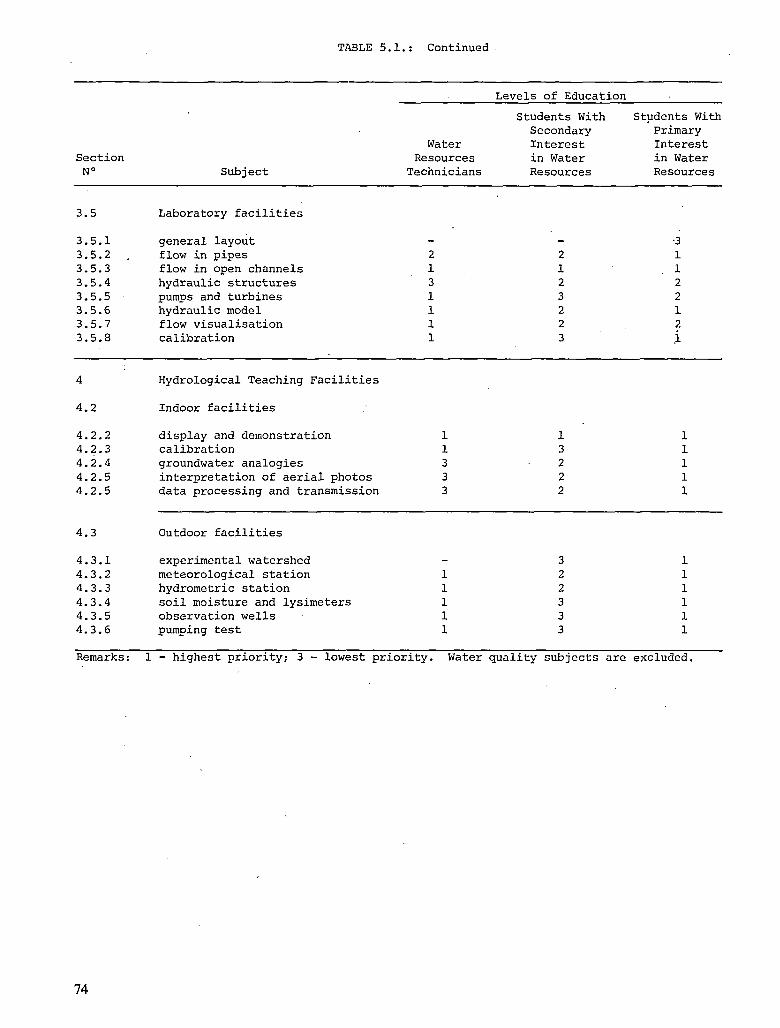
TABLE 5.1.: Continued
Section N° Subject
Levels of Education
Water Resources
Technicians
Students With Secondary Interest in Water Resources
Students With Primary Interest in Water Resources
3.5 Laboratory facilities
3.5.1 3.5.2 , 3.5.3 3.5.4 3.5.5 3.5.6 3.5.7 3.5.8
general layout flow in pipes flow in open channels hydraulic structures pumps and turbines hydraulic model flow visualisation calibration
•3
1 1 2 2 1 2
i
4.2
Hydrological Teaching Facilities
Indoor facilities
4.2.2 display and demonstration 4.2.3 calibration 4.2.4 groundwater analogies 4.2.5 interpretation of aerial photos 4.2.5 data processing and transmission
4.3 Outdoor facilities
4.3.1 experimental watershed 4.3.2 meteorological station 4.3.3 hydrometric station 4.3.4 soil moisture and lysimeters 4.3.5 observation wells 4.3.6 pumping test
Remarks: 1 - highest priority; 3 - lowest priority. Water quality subjects are excluded.
74

Bibliographies

CHAPTER ONE
Amorocho, J. and Brandstetter, A. 1971. Determination of non-linear response functions in rainfall-runoff relations. Water Resour. Res. 7(5). 1087-1101.
Chow, V.T., Fried, J.J., and Kuzek, R.J. 1975. International Seminar on Water Resources. UNESCO - International Water Resources Association, Paris-Strasbourg. IWRA.
Crawford, N.H. and Linsley, R.K. 1966. Digital simulation in hydrology. Stanford Watershed Model IV. Technical Report No. 12. Department Civ. Eng., Stanford University.
De Backer, L.W. 1978. Premanagement water resources study. NATO Advanced Study Institute on Water Resources and Land Use Planning, Louvain-la-Neuve, Belgium, 295-313.
de Marsily, G. 1971. La relation pluie-debit sur le bassin versant experimental de l'Hallue. Centre d'Informatique Géologique, Ecole Nat. Sup. des Mines de Paris, Fontainebleau LHM/R/71/15, 33 p.
Köhler, M.A. and Linsley, R.K. 1951. Predicting the runoff from storm-rainfall. Research Paper N° 34. U.S. Weather Bureau. Washington D.C.
Lorent, B. and Gevers, M. 1976. Identification of a rainfall-runoff process. Application to the1 Semois River. 4th I.F.A.C. Symposium on identification and system parameter. TBILISI, USSR, 10 p.
Osborne, H.B., Mills, W.C., and Lane, L.J. 1972. Uncertainties in estimating runoff producing rainfall for thunderstorm rainfall-runoff models. Inter. Symp. on Uncertainties in Hydrology and Water Resources Systems, Univ. of Arizona; Tucson, Vol. 1, p. 189-202.
UNESCO, Curricula and syllabi in Hydrology, Technical Paper in Hydrology N° 10.
UNESCO, Teaching aids in Hydrology, Technical Paper in Hydrology, N° 11.
UNESCO, The Teaching of Hydrology, Technical Paper in Hydrology, N°13.
UNESCO-WHO, 1978. Water quality surveys. A guide for the collection and interpretation of water quality data. IHD-WHO Working Grouj,, Studies and reports in Hydrology, N° 23.
World.Meteorological Organisation (WMO). 1974. Guide to hydrological practices, 3rd edition, Geneva.
77

CHAPTER TWO
Anonymous. 1975. Handbook of Data Communications. Manchester, U.K., the U.K. Post Office.
Deen, S.M. 1977. Fundamentals of Data Base Systems. London, Macmillan.
Doll, D.R. 1978. Data Communications, Facilities, Networks and System Design. New York, John Wiley and Sons.
Ellis, B. 1966. Basic Concepts of Measurement. Cambridge, U.K. University Press.
Feingold, C. 1971. Introduction to Data Processing. Dubuque, Iowa. Wm. C. Brown Publishers.
Gortier, H. 1975. Dimensionsanalyse. Berlin. Springer-Verlag.
Hall, C.W. 1977. Errors in Experimentation. Champaign, Illinois. Matrix.
Huntley, H.E. 1967. Dimensional Analysis. New York. Dover.
Isaacson, E. de St Q., Issacson, M. de St Q. 1975. Dimensional Methods in Engineering and Physics. London, Edward Arnold (Pub) Ltd.
Katzan, H. Jr. 1975. Computer Data Management and Data Base Technology. New York. Van Nostrand Reinhold.
Lewis, R. 1972. Engineering Quantities and Systems of Units. • London. Applied Science Pub.
London, K.R. 1974. Documentation Standards. London. Mason and Lipscomb.
Pugh, E.M.; Winslow, G.H. 1966. The Analysis of Physical Measurements. Reading, Mass. Addison-Wesley.
Sippl, C.J. 1976. Data Communications Dictionary. New York. Van Nostrand Reinho'ld.
Wood, W.G.; Martin, D.G. 1974. Experimental Method. Bath, U.K. Pitman.
Zuch, E.L. (ed). 1979. Data Acquisition and Conversion Handbook. Mansfield, Mass. Datel-Intersel.
78

CHAPTERS THREE AND FOUR
Ackers, P.; White, W.R.; Perkins, J.A.; Harrison, A.J.M. 1978. Weirs and Flumes'for Flow Measurement. John Wiley and Sons, New York.
Addison, H. 1949. Hydraulic Measurements. (2nd ed.), Chapman and Hall, London.
Albertson, M.L. and Tullis, J.P. 1967. Hydro Machinery Laboratory, Engineering Research Center, Colorado State University, Fort Collins, Coloardo.
Allen, J. 1947. Scale Models in Hydraulic Engineering. Longman Green and Co., London.
Anderson, E.W. 1974. Drainage basin instrumentation in fieldwork. Teaching Geography, No. 21, Geographical Association.
Asanuma, T. 1977. Flow Visualization. Proceedings of the International Symposium on Flow Visualization, Tokyo, Japan.
Anon. 1942. Hydraulic Models. American Society of Civil Engineers, New York.
Anon. 1976. Stevens Water Resources Data Book (2nd ed.), Leupold s Stevens Inc. Beaverton, Oregon.
Anon. 1977. National Handbook of Recommended Methods for Water Data Acquisition. Office of Water Data Coordination, U.S. Geological Survey, Reston, Virginia.
Bos, M.G. 1976. Field manual for research in agricultural hydrology. U.S. Department of Agriculture, Agricultural Research Service, Washington, D.C.
Brakensiek, D.L., Osborne, H.B., Rawls, W.J. 1979. Field manual for research in agricultural hydrology. Agriculture Handbook, NO. 24, U.S. Department of Agriculture, Washington, D.C.
Charlton, F.G. 1978. Measuring flow in open channels: A review of methods. Construction Industry Research and Information Association. London.
Chow, V.T. 1964. Handbook of Hydrology. McGraw Hill Book Co., New York.
Clayton, C.G. 1972. Modern Development in Flow Measurement. Peter Peregrinus Ltd., London.
Freeman, J.R. 1929. Hydraulic Laboratory Practice, American Society of Mechanical Engineers, New York, N.Y.
Gregory, K.J.; Walling, D.E. 1971. Field measurements in the drainage basin. Geography, Vol. 56, pp. 277-292.
Hellstrom, B.; Reinius, E. 1963. The Hydraulic Laboratory at the Royal Institute of Technology, Stockholm, Division of Hydraulics at the Royal Institute of Technology, Stockholm, Sweden, Bulletin No. 63.
Herschy, R.W. 1978. Hydrometry, Principles and Practice. John Wiley and Sons, New York.
IAHS-UNESCO. 1973. Results of Research on Representative and Experimental Basins. Proc. of the Wellington Symp., Vol. 1 and 2, UNESCO, Paris.
Kleinschmidt, R.S. 1958. Design of a Hydraulics Laboratory for Harvard University, Harvard University Sanitary Engineering, Reprint No. 25, (New Series) from Journal of the Boston Society of Civil Engineers, Vol. 45, pp. 397-409, No. 4.
Linford, A. 1961. Flow Measurement and Meters (2nd ed.), E.F.N. Spon Ltd., London.
Mathews, S.T. 1963. The Hydrodynamic Research Facilities of the National Research Council, National Research Council of Canada, Ottawa, Mechanical Engineering, Report No. MB-251.
Mathieson, R.; Stebbings, J. 1964. Design of a Modern Hydraulics Laboratory for Teaching and Research. Paper No. 6757, Proc. Instn. Civil Engineers, Vol. 29, pp. 657-676.
79

Motta, V.F. 1962. Report on Visits to European Hydraulics Laboratories, Universidade do Rio Grande do Sul, Instituto de Pesquisas Hidráulicas, Publ. No. 383, Universidade do Rio Grande do Sul, P. Alegre, Brasil.
Nemec, J. 1972. Engineering Hydrology. McGraw Hill Publishing Co., London..
Newson, M.D. 1979. Hydrology: Measurement and Application. Macmillan, London.
Shen, H.W. 1966. Visitation of Foreign Hydraulic Laboratories. Colorado State University, Publication No. CER67-68HWS31, Noc. 1967.
Simon, A.L. 1976. Practical Hydraulics. John Wiley and Sons Inc., New York, N.Y.
Toebes, C ; and Ouryvaev, V. 1970. Representative and Experimental Basins; an International Guide for Research and Practice. UNESCO, Paris.
UNESCO. 1969. The Use of Analog and Digital Computers in Hydrology (Proc. Tucson Symp.).
UNESCO-WMO-IAHS. 1973. Hydrometry. Proceedings of the Koblenz Symposium, Vol. 1 and 2, UNESCO, Paris.
USBR. 1953. Hydraulic Laboratory Practice, U.S. Dept. of the Interior, Denver, Colorado.
USBR. 1967. Water Measurement Manual. (2nd ed.). U.S. Dept. of the Interior, Denver, Colorado.
World Meteorological Organization. 1975. Modern Developments in Hydrometry. Vol. 1, WMO-427.
Yalin, M.S. 1971. Theory of Hydraulic Models. The Macmillan Press, Ltd., London.
Moisture Probe
Drost, H.; Moser, H.; Neumaier, F; and Rauert, W. 1974. Isotope methods in ground water hydrology. 'Euro Isotop Office, 136-140.
Gardner, W. and Kirkham, D. 1952. Determination of soil moisture by neutron scattering. Soil Science, 73, 391-401.
Hewlett, J.D. and al. 1964. Instrumental and soil moisture variance using the neutron scattering method. Soil Science, 97, 1, 19-24.
Hillel, D. 1974. L'eau et le sol. Ed. Vander, Louvain, 78-80.
Majerczyk, J.; Zuber, A. 1966. The influence of composition and density of soils on readings of neutron moisture probes. Radioisotope Instr., Industry Geophys. Pise. Symp., Warsawa.
Normand, M. 1969. La mesure de l'humidité du sol. Application aux problèmes d'hydraulique agricole, Cerafer, Bulletin Technique du Genie Rural, N° 103.
Tensiometer
Perrier, E.R. and Evans, D.D. 1961. Soil moisture evaluation by tensiometers. Soil Sc. Soe. Amer. Proc, 25, 3, 1973-1975.
Richards, L.A. 1942. Soil moisture tensiometer material and construction. Soil Science, 53, 241-248.
Richards, L.A. 1956. Soil suction measurements with tensiometers. Methods of soil analysis, American Soc. Agron., Monograph 9, 153-1.
Shishnov, K.N. 1962. Soil moisture meter and its use in the study of the behavior of soil moisture. Soviet Soil Science, 8, 963-868.
World Meteorological Organization. 1974. Guide to hydrological practice, 2.77-2.78.
80

Bouyoucos, G.. 1962. A continuous electric soil moisture recorder. Agronomy Journal, 54, N° 6, 549.
Croney, D.; Coleman, J.D.; and Currer, E.W.H. 1951. The electrical resistance method of measuring soil moisture. Brit. J. Appl. Sei., 2, 85-91.
Gluart, G.Y.; Baver, L.D. 1950. Salinity effects on soil moisture electrical resistance relationships. Soil Se. Soc. Am. Proc, 15, 56-63.
Weaver, H.A.; and Jamison, V.C. 1951. Limitations in the use of electrical resistance soil moisture units. Agron. J., 43, 602-605.
Lysimeter
De Backer, L. W. and J. Batardy. 1979. Actual évapotranspiration measured by high accuracy lysimeter. Hydrology Symposium EGS, Vienne, EOS, Trans. AGU, vol. 60, p. 582.
Hillel, D. and al. 1969. New design of a low cost Hydraulic lysimeter for field measurement of évapotranspiration. Israel J. Agr. Res. 19, 57-63.
Pelton, W.L. 1961. The use of lysimetric methods to measure évapotranspiration. Proc. Hydrol. Symp., 2, 106-134.
Van Bavel, C.H.M. and Myers, L.E. 1962. An automatic weighing lysimeter. Agr. Eng., 43, 580-583.
Wells and Pumping Tests
Chow, V.T. 1964. Advances in hydroscience. Academic Press, New York, London.
Davis, S.N. and De Wiest, R.J.M. 1966. Hydrogeology. John Wiley and Sons, New York, 463 p.
Drost, W.; Moser, H.; Neumaier, F.; and Rauert, W. 1974. Isotope methods in groundwater hydrology. CED, Brussels, Eurisotop 61, Monograph 16, 176 p.
Fried, J.J. 1975. Groundwater pollution. Theory, methodology modelling and practical rules. Elseviers Sc. Pub. Co., Amsterdam, Oxford, N.Y., 330 p.
Johnson, E.E. 1966. Groundwater and wells. E.E. Johnson, Inc., St. Paul, Minn., 440 p.
Kruseman, G. P. and De Ridder, N.A. 1973.' Analysis and evaluation of pumping test data. International Institute for Land Reclamation and Improvement (ILRI), Bulletin N° 11, 2nd edition, Wageningen.
Schneebeli, G. 1966. Hydraulique souterraine, Eyrolles, Paris.
UNESCO-WHO. 1978. Water Quality Surveys. A guide for the collection and interpretation of water quality data. Co-ed. UNESCO-WHO, Paris-Geneva, Studies and Reports in Hydrology, N° 23, 350 p. (ISBN 92-3-101473-0).
CHAPTER FIVE
Albina, H. Hydraulica General. Trabajos de Laboratorio. 2 vol., Centro de Estudiantes de Ingenieria. La Plata.
Albina, H. and Lopardo, R.A. 1970. Una Experiencia sobre método logia de la enseñanza practica de la hidráulica, Sem. de la enseñanza IV Congreso Latinoamericano de Hidráulica IAHR, Mexico.
Chow, V.T. 1959. Open channel hydraulics, McGraw Hill, Tokyo.
Fordham. 1948. On the calculations of surface tension from measurement of pendant drops, Proc. Royal Soc, 194, Al.
Freeman, J.R. 1929. Hydraulic Laboratory .Practice, American Society of Mechanical Engineering.
Freire Motta, V. 1952. Report on visits to European hydraulics laboratories, Universidade do Rio Grande do Sul, Porto Alegre.
Gridel, H. 1955. Le laboratoire National D'Hydraulique de Chatou, No. 247 de Travaux, Paris, Mai.
Gyorke, 0. 1973. European hydraulics laboratories: a survey, UNESCO, Paris.
Hellstrom, B. and Reinius, E. 1963. The Hydraulic Laboratory at the Royal Institute of Technology, Stockholm, Division of Hydraulics at the Royal Institute of Technology, Stockholm, Sweden, Bulletin No. 63.
I.M.F. Universite de Toulouse. Guide des travaux pratiques, Toulouse (France).
Knapp, R.T. 1936.' The hydraulic-machinery laboratory at the California Institute of Technology, A.S.M.E. Transactions, pp. 663-676.
Knapp, R.T.; Levy, J..; O'Neill, J.P.; and Brown, F.B. 1948. The Hydrodynamics Laboratory of the California Institute of Technology, Transactions of the ASME, pp. 437-457.
Lopardo, R.A. and Albina, H.• 1970. Los trabajos prácticos de iniciación a la investigación en la enseñanza de la hidráulica, IAHR, IV Congreso Latinoamericano de Hidráulica, Seminario de Enseñanza, Mexico.
Lopardo, R.A. and Guaycochea, D. 1980. Disendo y verificación sobre modelo de un vertedero de gran altura. Pautas para un trabajo practico, C.E.I.L.P., La Plata, Argentina.
Macagno, E.O. 1961. Teoria y experiencia en mechanica de fluidos, Consejo Nac. de Investigaciones Cient. y Técnicas, Buenos Aires.
Martinez Fonseca, R. 1980. Dispositivos modulares en la enseñanza de la hidráulica, IAHR, IX Congreso Latinoamericano de Hidráulica, Merida (Venezuela), (pag. 589-595) .
NEUFERT. 1958. Nave de ensayos hidráulicos, Escuela Superior Técnica de Darmstadt. Revista Informes de la Construcción N° 105, Instituto Técnico de la Construcción y del Cemento.
NEYRPIC. 1951. The Neyrpic Hydraulic Research Laboratory, General Outline, Laboratoire Dauphinois D'Hydraulique, Grenoble.
Rouse, H. 1961. Laboratory Instruction in the Mechanics of Fluids, University of Iowa, Iowa City.
Schuyf, J.P. 1966. The measurement of turbulent velocity fluctuations with a propeller-type current meter, Journal of Hydraulic Research, Vol. 4, N°2, 1966, pag. 37-54.
Schwedes, K. and Weiher, H. 1977. Water Level transducer for niveau-and-wave measurements, Proc. XVII IAHR Congress, Baden-Baden, vol. 6, pag. 587-591.
82

Shen, H.W. 1967. Visitation of Foreign Hydraulic Laboratories, Colorado State University, Publication N° CER67-68HWS31.
Simmler, H. 1965. Institut fur Wasserwirtschft und Konstruktiven Wasserbau an der Techischen Hochschule Graz, Das Neue Institut fur Wasserbau, Graz.
SOGREAH. Hydraulic laboratory equipment, Grenoble, France.
Stelczer, K. Hydraulic models, Teaching Aids in Hydrology, UNESCO Technical Papers in Hydrology N° 11.
Troskolanski, A.T. Theorie et pratique des mesures hydrauliques, Dunod, Paris.
Bureau of Reclamation. 1958. Hydraulic Laboratory Practice, Engineering Monograph N° 18, Denver, Colorado.
Van Wazer, J.R.; Lyons, J.W.; Kim, K.Y.; and Colwell, R.E. 1963. Viscosity and flow measurement, Interscience, New York.
Various Catalogues. Armfield, Sogreah, Gilkes, Italia, Didacta, Iowa University, Plint, Altech Coimbatore, etc.
World Meteorological Organization. 1971. Use of weirs and flumes in stream gauging. Technical Note N° 117, WMO-N° 280, Geneve.
83

ISBN 92-3-102107-9