
Technical manual for the EMC 10/4 embroidery peripheral · •Four Melco Embroidery Heads • 10...
124
• Four Melco Embroidery Heads • 10 Needles with automatic color change • Automatic Trimmer Option Technical manual for the EMC 10/4 embroidery peripheral Part Number 110305-01, Revision A European Compliance Version A Saurer Group Company
Transcript of Technical manual for the EMC 10/4 embroidery peripheral · •Four Melco Embroidery Heads • 10...
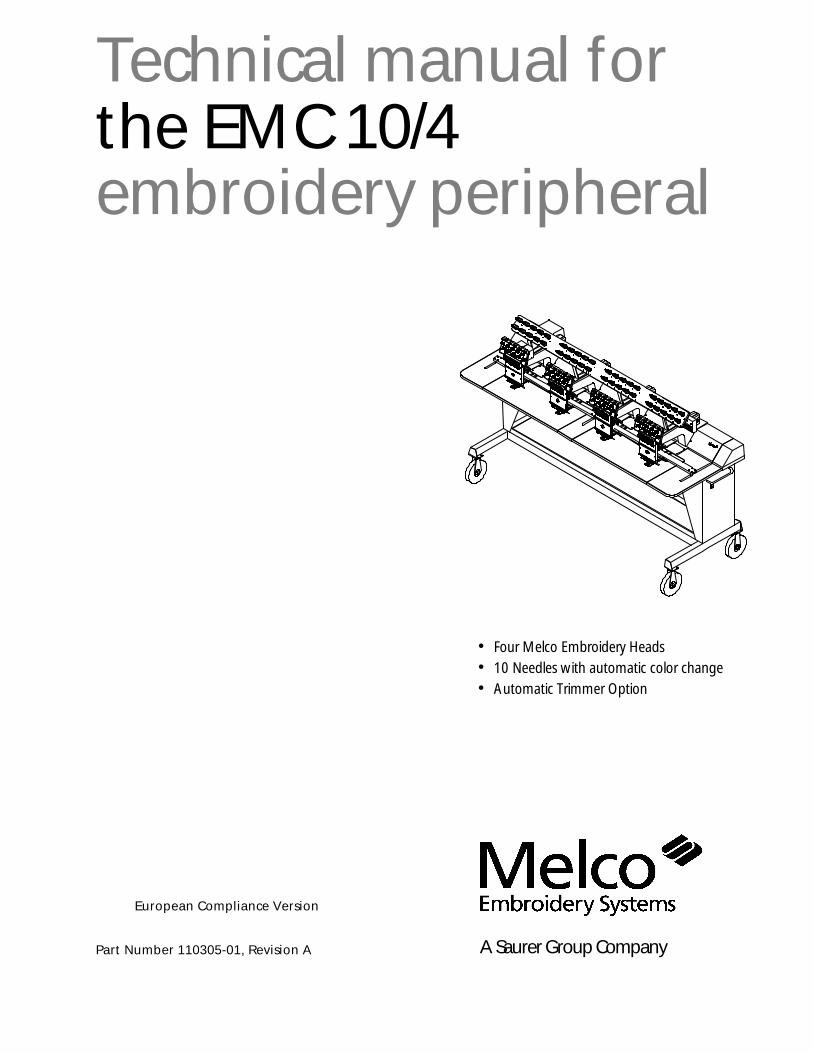
• Four Melco Embroidery Heads• 10 Needles with automatic color change• Automatic Trimmer Option
Technical manual forthe EMC 10/4embroidery peripheral
Part Number 110305-01, Revision A
European Compliance Version
A Saurer Group Company

1575 West 124th AvenueDenver, Colorado 80234United States of AmericaInternet Address: [email protected]
Copyright © Melco Embroidery Systems, 1996
ALL RIGHTS RESERVED No part of this publication may be reproduced, stored in a retrieval system, ortransmitted in any form or by any means (electronic, mechanical, photocopying, recording, orotherwise) without prior written approval of Melco Embroidery Systems. Melco reserves the right torevise this publication and to make changes in it at any time without obligation of Melco to notify anyperson or organization of such revisions or changes.
All precautions have been taken to avoid errors or misrepresentations of facts, equipment, orproducts. However, Melco Embroidery Systems does not assume any liability to any party for loss ordamage caused by errors or omissions.
Printed in the United States of America
First Printing: June, 1996

Table of Contents
1. Introduction 1 - 1
Scope Of Manual 1 - 1Warranty Registration 1 - 1Standard Conventions Used In Manual 1 - 1Explanation Of Symbols 1 - 2Glossary Of Terms 1 - 3Maintenance Philosophy 1 - 3
Static Electricity And Grounding Strap Use 1 - 3Warranty Considerations 1 - 3
System Overview 1 - 3Physical/Functional Arrangement 1 - 4Configuring the EMC 10/4 1 - 5
Configuration Procedure 1 - 6
2. Service Adjustments 2 - 1
General 2 - 1Drive Belt Tensions 2 - 1Physical/Functional Identification 2 - 1
Controller Section 2 - 1Keyboard Section 2 - 2
Display Screen Intensity 2 - 2Carriage Section 2 - 3
Carriage Set Home Position 2 - 3X Drive Belt Tension 2 - 5Y Drive Belt Tensions 2 - 7
Under Carriage Section 2 - 8X Motor Belt Tension 2 - 8Y Motor Belt Tension 2 - 9AC Input Voltage Selection 2 - 9Power Supply +5 Volt Adjustment 2 - 10
Head Section 2 - 12Z Drive Mechanical System 2 - 12
Z Drive Motor Belt Tension 2 - 13Synchronizing The Embroidery Heads 2 - 13
Z Encoder System Introduction 2 - 16Z Encoder Inspection 2 - 17Z Shaft Encoder Calibration 2 - 18Thread Tensioner Check Spring Adjustment 2 - 19
Adjustment Hints 2 - 20Cross Roller Bearing Centering 2 - 21Retainer Plate Bearing Adjustment 2 - 22
Alternate Method 2 - 23Lower Rail Retainer Adjustment 2 - 24Jump Stitch Solenoid 2 - 25
i EMC 10/4 Technical Manual

Plunger Positioning 2 - 25Bracket Positioning 2 - 26
Color Change Motor Belt Tension 2 - 27Thread Break Brush Adjustment 2 - 28
Head #4 2 - 28Head #s 1, 2, and 3 2 - 28
Trimmer Option 2 - 30Sequence of Trim Events 2 - 30Trimmer Set Up And Adjustments 2 - 31Z Timeout Errors 2 - 31Trimmers Not Trimming Properly 2 - 33Spring Knife 2 - 34Under Thread Presser 2 - 37Movable Knife 2 - 38Checking Select Position 2 - 41Select Position Adjustment 2 - 42Picker Finger Centering 2 - 43Picker Home Position 2 - 44Picker Height/Depth Position 2 - 44Grabber Adjustments 2 - 45
Under Thread Control (UTC) Adjustments 2 - 48Rotary Hook Retaining Finger Positioning 2 - 48
Sew Test 2 - 50Preliminary Checks 2 - 51Perform The Test 2 - 51
3. Mechanical Disassembly 3 - 1
General 3 - 1Static Electricity / Grounding Strap Use 3 - 1
Embroidery Peripheral 3 - 2Removing the Rear Covers 3 - 2
Controller Section Rear Cover #4 3 - 3Removing the Tensioner Covers 3 - 3
Controller Section 3 - 5EMI Box Cover Removal 3 - 5CPU PCB Replacement 3 - 6Trimmer Interface Board Replacement 3 - 7Backplane PCB Replacement 3 - 8
Keyboard Section 3 - 8Keyboard/Display Replacement 3 - 8
Carriage Section 3 - 10X Drive Belt Replacement 3 - 10Y Drive Belt Replacement 3 - 12
Under Carriage Section 3 - 14X and Y Drive Motors and Belts 3 - 14X Y Z Motor Drives 3 - 15Power Supply Replacement 3 - 17
Table of Contents
EMC 10/4 Technical Manual ii

Head Section 3 - 18General 3 - 18Arm and Bed Assembly 3 - 18Z Motor Replacement 3 - 19Z Shaft Encoder Installation 3 - 20Thread Tree Assembly Removal 3 - 22Removing the Thread Tensioner Bracket Assembly 3 - 23Replacing An Individual Thread Tensioner 3 - 24Changing A Check Spring 3 - 24Replacing A Thread Break Contact Post 3 - 26Replacing The Thread Break Wiper Brush 3 - 27
Head #4 3 - 27Head #s 1, 2, and 3 3 - 28
Replacing A Needle Bar 3 - 28Needle Case Removal 3 - 31
Head #4 3 - 31Head #s 1, 2, and 3 3 - 31
Installing Needle Case 3 - 33Head #4 3 - 33Head #s 1, 2, and 3 3 - 35
Replacing Needle Case Cross Roller Bearing 3 - 36Needle Centering 3 - 36
Replacing Reciprocator / Needle Bar Guide Shaft 3 - 37Jump Stitch Solenoid Replacement 3 - 39
Head #4 3 - 39Head #s 1, 2, and 3 3 - 40
Color Change PCB Replacement 3 - 41Color Change Motor Replacement 3 - 43Color Change Cam Assembly Replacement 3 - 44Trimmer Assemblies 3 - 45
Grabber Drive Assembly 3 - 45Grabber Blade 3 - 46Trimmer Drive Assembly 3 - 48Picker Solenoid Assembly 3 - 49Home Position Optical Switch 3 - 50Picker Assembly 3 - 50Movable Knife 3 - 51Movable Knife Drive Arm 3 - 53
UTC Replacement 3 - 54
INDEX
Table of Contents
iii EMC 10/4 Technical Manual

This page intentionally left blank
Table of Contents
EMC 10/4 Technical Manual iv

1. Introduction
Scope Of Manual
The EMC 10/4 Embroidery Peripheral Technical Manual is designed to provide theuser with information necessary to perform repairs beyond routine operatormaintenance.
The Melco EMC 10/4 Embroidery Peripheral is one of several embroidery peripheralsin Melco’s EDS II and EDS III family of products. The EMC 10/4 is a four headembroidery machine, which is assembled with the Melco ten-needle, cylinder armembroidery heads. It is designed to allow for flat goods and cap frame embroidery.It is equipped with an Under Thread Control (UTC) device which is used to detectthe presence of bobbin thread. An optional Thread Trimmer system is also available.
This technical manual is presented in three basic sections: 1) an overview of generalinformation, such as the proper configuration of the peripheral, found in thisintroductory section, 2) service adjustments, and 3) mechanical disassembly andreplacement of the major components of the embroidery peripheral.
Warranty Registration
Please complete the Warranty Registration form upon installation of the system;and return it to Melco to validate and register the machine warranty. If no WarrantyRegistration is on file at Melco when warranty service is requested, it will beassumed that your warranty began on the 7th day after the ship date from Melco.
Standard Conventions Used In Manual
Throughout this manual several abbreviations and specific terms may be used. Thefollowing explains some of this terminology:
When referring to the Embroidery Peripheral or peripherals, the initials "EP" or"EPs" may occasionally be used. When speaking of a "printed circuit board," theitem may quite often be referred to as a "PCB."
The terms "X Beam", "Y Beam", "Beam", "Carriage", "Carriage Assembly" and"Pantograph" may all refer to the same general area. Specifically, the Pantographconsists of the Y Beam (the part that moves forward and backward) and the XCarriage (the part within the Y Beam that moves left and right, and to which thehoops or cap frame drivers are attached).
Certain procedures in the manual require actions such as pressing a certain key, ortyping some letters at the computer keyboard. The following is a list of some of themore commonly used conventions found in this manual.
• To indicate a key on the computer keyboard, it is referred to as simply thekey in question, for example: Press the Enter key to initiate the application.
1 - 1
110305-01, Rev A 1. Introduction

• Typing with the computer keyboard is referred to in BOLD letters, forexample: Type: run and press Enter to start.
• To indicate that two keys must be pressed simultaneously the followingconventions are used: with the computer keyboard, the first key to bepressed and held down is simply referred to, then the second key whichneeds to be pressed while the first key is held down is referred to after acomma, for example: Press Shift,8 to type an asterisk (*).
Explanation Of Symbols
Caution!
Indicates a machine component will move. Keep clear!
Shock hazard. No user replaceable parts behind this label. Do not open!
Pinch point, Keep clear!
Pinch point, Keep clear!
Pinch point, Keep clear!
1 - 2 Explanation Of Symbols
EMC 10/4 Technical Manual Melco Embroidery Systems

Glossary Of Terms
Several words or terms are used in this manual that are unique or specialized in usewith the embroidery industry or Melco embroidery equipment. A glossary of theseterms is located in the appendix section of the EMC 10/4 Operation manual. Referto that appendix for information on terms that may be unfamiliar to you.
Maintenance Philosophy
The maintenance philosophy used in this manual, and practiced at Melco, is toisolate potential problems within the system to a "practical" replacement assembly.Therefore, components are typically not repaired, but rather, a circuit board ormechanical "assembly" may be replaced. In the process of isolating problems in themachine, the person performing the trouble shooting must also practice goodtrouble shooting techniques. Good trouble shooting techniques include, but are notlimited to, guarding against static electricity causing damage to machinecomponents.
Static Electricity And Grounding Strap Use
The embroidery peripheral electronic circuits are quite sensitive to static electricity.Melco recommends that personnel use anti-static techniques when performingmaintenance on the machine.
Failure to use a grounding strap, or failure to practice other good maintenance orrepair techniques may cause damage to the machine and possible harm topersonnel.
Warranty Considerations
Some areas of maintenance require factory trained personnel to assure properservice. If unauthorized personnel attempt to service these areas, the FACTORYWARRANTY MAY BE VOIDED.
Therefore, it is recommended that Melco factory trained personnel be consultedwhenever the "FACTORY SERVICE ADVISED" statement is noted with a procedure.
Although areas marked specifically for factory service are subject to voiding thewarranty if performed improperly, any service that is improperly performed maycause the warranty to be voided.
System Overview
The EMC 10/4 Embroidery Peripheral alone is not a productive unit until it is linkedto an EDS program or the Disk Drive Option program. Once the EMC 10/4 isdownloaded by one of these programs, they combine into a system to producehigh quality embroidered goods.
Warranty Considerations 1 - 3
110305-01, Rev A 1. Introduction

Physical/Functional Arrangement
The EMC 10/4 may be divided into several distinct physical and/or functional areasof description (see Figure 1-1). All the computerized controls are housed under therear covers between the far left (#4) embroidery head and the second embroideryhead from the left (#3). This area is called the Controller Section.
The power supply is located in the area under the rear cover between the far right(#1) embroidery head and the second embroidery head from the right (#2).
The keyboard is located between the tensioner assemblies of the middle two heads(#2 and #3).
Another area, the Carriage Section, consists of the mechanical devices that hold thegarments and move them forward and backward (y beam) and left to right (xcarriage). The x carriage and y beam assembly is located just above the table topand positioned under the embroidery head arms. The carriage section also consistsof the drive belts, pulleys, and shafts associated with the device, and the carriagecentering mechanics and electronics. The motors that drive the carriage are afunctional part of the carriage section but are physically located under the carriage,in the frame of the peripheral called the Under Carriage Section.
Controller Section(under rearcover #4)
Carriage Section
Keyboard Section
Embroidery Head Section (head #1)
Under Carriage Section
Figure 1 - 1
1 - 4 System Overview
EMC 10/4 Technical Manual Melco Embroidery Systems

The Under Carriage Section is described as that area under the embroidery headplatform and within the frame support legs. The X and Y drive motors arepositioned directly under the embroidery head platform between the middle twoembroidery heads ( #2 and #3). In addition to the motors, the under carriagesection contains the X, Y, and Z motor drive electronics inside the left framesupport leg; and the AC power input module inside the right frame support leg.
Another distinct section of the EMC 10/4 is the Embroidery Head Section. Thissection consists of each of the 4 heads, the Z drive motor and associated head drivemechanics and the optional trimmer devices.
Please note that Sections 2 and 3 of this manual are laid out in accordance with theabove machine functional/physical descriptions.
Configuring the EMC 10/4
Occasionally during the operation of the EMC 10/4, certain situations may arisewhen the peripheral software simply "locks up."
You may often recover from this type of situation by performing what is called"Configuring" (or Re-configuring) the embroidery peripheral. (When this type ofsituation happens with a computer, you are usually asked to perform a "softreboot" [Ctrl], [Alt], [Del].)
You must also configure the peripheral any time you install a new CPU (CentralProcessor Unit) printed circuit board.
Configuration is initially set at the factory. However, if for any reason theconfiguration is not set properly, or if you have replaced the CPU board, you shouldknow how to set the configuration.
NOTICE: Re-configuring your EMC 10/4 will clear the power fail rescue function forthe current situation.
There are three items that must be set in each EMC 10/4 Embroidery Peripheralbefore it is used in the Melco system for the first time.
First you must set the Peripheral Program. The CPU PCB used on the EMC 10/4Embroidery Peripheral may also be used in other embroidery peripherals producedat Melco. Therefore, you must tell the CPU board what peripheral it is being used in.
If the CPU PCB is ever replaced, you must reconfigure the peripheral before using itagain.
CAUTION! If the EMC 10/4 is not configured with the correct Peripheral Program, itwill not run properly, and may become damaged.
Configuring the EMC 10/4 1 - 5
110305-01, Rev A 1. Introduction

The second configuration item is the network address (or Unit Number). The UnitNumber must be set and be different for each peripheral attached to an EDS II orEDS III computer or network. There may be up to 64 (16 if using EDS II software)total embroidery peripherals attached to any one computer, and each must have itsown Unit Number. The number is selected from the peripheral Keyboard and isbetween 1 and 64 (16 if using EDS II software).
The third and last configuration item is to choose if you want the Display Languageto appear in English or Spanish.
The ‘‘configuration mode’’ in the EMC 10/4 is accessible by pressing a certainkeystroke combination while switching ON the power. When the EMC 10/4 isinitially turned ON, and any time you wish to change the configuration status of themachine, refer to the following steps:
NOTE: If the Peripheral Program has not been downloaded (the programand unit number alternately show on the display), you can also enter intothe configuration mode without turning the machine OFF, then ON again.
Configuration Procedure
1. Before you turn ON the EMC 10/4 (or if the unit has not yet been"downloaded"), locate the 10-key keyboard at the front of the peripheral unit,between heads #2 and #3.
2. Also locate the power switch at the right end of the unit (see Figure 1-2).
3. Turn ON the EMC 10/4 by moving the power switch to the ON position; andwithin 5 seconds, press and hold the 3 keys ON the peripheral keyboard marked: , , and .
4. Hold these keys depressed until the unit ‘‘beeps’’ and the display shows amessage depicting the Peripheral Program currently selected.
PowerSwitch
Figure 1 - 2
1 - 6 System Overview
EMC 10/4 Technical Manual Melco Embroidery Systems

The peripheral will now be in the ‘‘configuration mode,’’ and you can release the 3keys.
NOTE: If the unit is already ON, but has not yet "downloaded," you need only todepress and hold the 3 peripheral keyboard keys until the unit beeps toget into the configuration mode, then proceed. You do not need to turnthe EMC 10/4 OFF, then ON again.
When the EMC 10/4 is in the ‘‘configuration mode,’’ you can set (or change) thePeripheral Program, Unit Number, and Display language for the machine.
PeripheralProgram
5. To set the Peripheral Program, simply depress the or keys on theperipheral keyboard until the correct program shows on the display. Theprograms specific to the EMC 10/4 are: EMC 10/4, (without trimmers), or EMC10/4T (with the trimmer option). After getting the proper program nameshowing on the display, depress the key on the peripheral keyboard to"set" the program.
Unit Number 6. After the key is depressed the configuration item will go to the Unit Numberselection. To select a Unit Number, again simply depress the or keyson the peripheral keyboard until the desired Unit Number shows on the display.(You cannot have two peripherals with the same Unit Number attached to anEDS operating system.) After the desired number is showing on the display,depress the key on the keyboard.
DisplayLanguage
7. The last item you may select in the configuration mode is the language used forshowing the information in the display. Again, depress the or keys onthe peripheral keyboard until English or Spanish appears on the display.
8. After the desired language is showing on the display, depress the key onthe peripheral keyboard.
The EMC 10/4 configuration is now complete.
Configuring the EMC 10/4 1 - 7
110305-01, Rev A 1. Introduction

This page intentionally left blank
1 - 8 System Overview
EMC 10/4 Technical Manual Melco Embroidery Systems

2. Service Adjustments
General
This section of the manual provides detailed information for performing machineadjustments required during maintenance or parts replacement. The procedures areguidelines for performing service maintenance, and must be used by personnelpracticing good maintenance technique. Good maintenance technique includes,but is not limited to, adhering to all precautions and safety considerations whenworking on the unit; and using the correct tools for the job being performed.
It is recommended that some procedures in this section be performed by factorytrained personnel to obtain best results. This reference is indicated by stating"FACTORY SERVICE ADVISED" at the start of the procedure.
Drive Belt Tensions
"FACTORY SERVICE ADVISED"
CAUTION! Damage to the machine may result if belt tensions are improperlyperformed.
All drive belts require special procedures and tools for setting the proper tensions. Ifthe tension settings are attempted without using the proper procedures and tools(and without proper training in some cases), machine components may bedamaged. If a belt tension adjustment is needed, follow the procedure in themanual or, if "factory service is advised," contact your local factory trained servicerepresentative.
Physical/Functional Identification
As discussed in Section 1 of this manual, the EMC 10/4 is functionally and/orphysically arranged into several sections. This section of the manual is laid out inaccordance to those machine areas. To identify these areas refer to Section 1 of themanual.
Controller Section
The controller section is so named because of its many controlling functions.Located within the controller section is the CPU PCB. the CPU processes data andtranslates instructions that are input to the unit by the operator. The TrimmerInterface PCB is also located in the controller section. This PCB helps to interpretdata relating to such things as color change, embroidery speed, and trimmer timing(with trimmer option).
Although no adjustments are performed inside the controller section of the EMC10/4, there are occasions when reference is directed to this section to monitor ormeasure the results of other adjustments.
Physical/Functional Identification 2 - 1
110305-01, Rev A 2. Service Adjustments

Keyboard Section
Operator control of the EMC 10/4 is performed through the keyboard keys. Thedisplay, in turn, provides machine communication back to the operator.
Display Screen Intensity
Adjusting the intensity of the display requires the removal of machine covers togain access to the adjusting potentiometer on the keyboard PCB.
1. Turn OFF the power switch to the EMC 10/4.
2. Remove the long rear tensioner cover from behind the keyboard (refer toChapter 3 for removal information).
3. The rear of the keyboard is now exposed and accessible from the rear. Locate theintensity adjustment pot on the right side of the keyboard printed circuit boardas shown in Figure 2-1.
4. Turn ON the power switch to the EMC 10/4.
5. While watching the display from the front, reach under or over the keyboardassembly to the adjustment potentiometer and rotate it clockwise to increaseintensity on the display, or counterclockwise to decrease the intensity on thedisplay.
6. After the desired intensity is obtained, turn OFF the power to the EMC 10/4 andreinstall any and all covers and screws removed to make this adjustment.
KeyboardPCB
KeyboardCover
intensityadjustmentpotentiometer
Figure 2 - 1
2 - 2 Keyboard Section
EMC 10/4 Technical Manual Melco Embroidery Systems
Carriage Section
This section consists of the mechanical device and associated parts for securing andmoving the hoops in the x and y coordinates during the stitching process. Thisassembly is sometimes referred to as the pantograph. The main cross memberconsists of 2 basic parts, the X carriage and the Y beam.
The X carriage has the 4 hoop holders attached to it and the X carriage itself issecured inside the Y beam. It is driven left and right by a single belt within theassembly. This belt is driven by the spline shaft. The spline shaft is attached to the Xmotor through a belt and pulley arrangement.
The Y beam is secured at each end to a sliding bushing and shaft combinationwhich allows forward and backward movement of the beam. The Y beam is drivenby a drive belt at each end and 2 drive belts in the middle. The beam ismechanically coupled to the Y drive motor through these 4 belts, a long belt driveshaft, and the motor drive belt.
Carriage Set Home Position
When the set home function is initiated, the pantograph moves to the center of theembroidery field and then returns to its previous position. The left to right centerposition of the carriage is determined by the X home disk position in reference tothe position detect PCB at the front of the X carriage ball spline drive shaft. Theserelative positions may be changed whenever the X carriage drive belt is removed orreplaced. The position of the X home disk assembly must therefore be checked andadjusted at the mechanical center of the X carriage movement.
The most forward disk of the 3 disks in front of the ball spline shaft should becentered (or very nearly centered) at the bottom of the front support bracket asshown in Figure 2-3. If not centered, you must move the X carriage belt withoutmoving the X carriage from its centered position.
"FACTORY SERVICE ADVISED"
Note: Performing this procedure results in the need for setting X belt tensionwhich in turn requires using a special service tool.
1. Turn OFF the embroidery peripheral and unplug the power cord.
2. Remove the table top inserts and the middle table top section.
3. Position the X carriage approximately at the center of the embroidery field.
4. Install a cap frame driver to one of the heads. (If the cap frame option is not onthis unit, skip to the next step.)
Carriage Set Home Position 2 - 3
110305-01, Rev A 2. Service Adjustments

5. Position the X carriage left/right movement to center the cap frame driver hoopnotch directly over the cylinder arm cover of the embroidery head as shown inFigure 2-2. (If no cap frame driver, center the hoop attaching mechanism overthe cylinder arm as best as you can determine.)
6. Loosen the 2 phillips screws at each X carriage belt clamp (see Figure 2-5). Byrotating the socket head cap screws counter-clockwise evenly at the ends ofboth clamps, loosen the X carriage belt enough to allow it to slip around thespline shaft pulley.
7. Rotate the spline shaft (allowing the X carriage belt to slip around the pulley)until the front disk is centered (or very nearly centered) at the bottom of thefront support bracket as Figure 2-3 shows.
8. By rotating the socket head cap screws clockwise evenly at the ends of bothclamps, tighten the X carriage belt enough to keep it from slipping during theremainder of this procedure.
9. Insure the cap frame driver hoop notch is still directly over the cylinder arm coverwhen the front disk is centered at the bottom of the front support bracket andremove the cap frame driver.
Cap FrameDriver
Cap FrameGuide toArm Covercenterline
ArmCover
CapFrameGuide
Needle Plate
Figure 2 - 2
2 - 4 Carriage Section
EMC 10/4 Technical Manual Melco Embroidery Systems

10. Refer to the following X Drive Belt Tension procedure to retension the belt.
X Drive Belt Tension
"FACTORY SERVICE ADVISED"
Note: This procedure requires using a special service tool: the X-Belt Fixture, partnumber 995509-01.
1. Turn OFF the embroidery peripheral and unplug the power cord.
2. Remove the table top inserts and the middle table top section.
3. Position the X carriage to the center of the embroidery field by centering one ofthe threaded inserts on the bottom of the carriage over the center of theembroidery head bed covers as shown in Figure 2-5.
4. Check the set home position and adjust if required by referring to the previousprocedure.
5. Inspect the two X carriage belt ends under the carriage assembly (see Figure 2-4).The clamps at each end should be the same distance from the socket head capscrew mounts.
6. Loosen the 2 phillips head screws that secure the X carriage belt clamps to the Xcarriage at both ends of the X carriage belt (see Figure 2-4).
right side of theMost ForwardDisk protrudingthe same amountas the left side
left side of theMost Forward Diskprotruding thesame amount asthe right side
Front Support Bracket
Figure 2 - 3
X Drive Belt Tension 2 - 5
110305-01, Rev A 2. Service Adjustments

7. With the carriage still centered, attach the X-Belt Fixture (p/n 995509-01) ontothe x carriage belt, centered between the spline drive pulley and one of the endclamps as shown in Figure 2-5.
8. When properly tensioned, the fixture hanging arm will just be touching theunder side of the carriage foam. If it is touching when first installed, you mustloosen the belt enough to see clearance between the hanging arm and thefoam and then re-tension.
9. At the end of the X carriage belt with the largest gap between the socket headcap screw mount and the belt clamp, turn the socket head cap screw clockwiseto tighten the belt.
NOTE: When tightening the belt tension you will want to tighten evenly at the eachend to maintain nearly even gaps between the clamps and the mounts.
10. Continue to tighten the socket head cap screw until the fixture hanging arm justtouches the under side of the carriage foam.
11. Remove the fixture and tighten the 2 phillips head screws that secure the Xcarriage belt clamps to the X carriage at both ends of the X carriage belt.
12. Reattach the middle table top section and the table top inserts.
socket headcap screw
Left Xcarriagesection
X carriage beltphillips headscrew (2 ea)
belt clamp
Figure 2 - 4
phillips screws
X carriage beltsocket headcap screw
X-Belt Fixture(995509-01)
threadedinsert
embroidery head bed
Figure 2 - 5
2 - 6 Carriage Section
EMC 10/4 Technical Manual Melco Embroidery Systems

Y Drive Belt Tensions
Note: This procedure requires the use of a special service tool: the Gates 5MTensiometer, available from Melco, part number 992165-01.
1. Remove all table tops and move the Y beam all the way to the rear.
2. Properly attach a Gates 5M Tensiometer to the belt, midway between the beamand the idler pulley tensioning assembly (see Figure 2-6) and check the tension.
3. The tension scale should read 20 plus or minus 1 with the Gates tensiometer.
4. Adjust as described in the following steps, checking the tension with thetensiometer frequently until the proper value (20 ± 1) is measured.
a) Tighten the belt tension screw at the front of the idler pulley bracketclockwise to increase the belt tension.
b) Loosen the belt tension screw at the front of the idler pulley bracketcounterclockwise to decrease the belt tension.
5. Repeat the above procedure for all the Y drive belts to ensure that they are"balanced" (tensioned the same).
6. Reinstall the table tops that were removed earlier.
Y carriageand beam
Gates 5MTensiometer
midway betweenthe beam and theidler pulley
belt tensionscrew
idler pulley
Figure 2 - 6
Y Drive Belt Tensions 2 - 7
110305-01, Rev A 2. Service Adjustments

Under Carriage Section
This section is physically located in and about the peripheral support framework. TheX and Y motors are attached under the embroidery head platform, and the powersupply and motor drivers are found inside the frame support legs at either end.
X Motor Belt Tension
Note: This procedure requires using a 0 to 40 pound special service tool pull gauge.
1. Loosen the 4 X motor socket head cap screws enough for the motor to move onthe motor bracket. (Refer to Figure 2-7.)
2. Wrap a piece of small, strong cable or cord around the X motor drive pulley tothe side nearest the motor.
3. Form loops in the ends of the cable or cord and hook a 0 to 40 pound pullgauge into the loops.
4. Pull straight down on the pull gauge until it reads 30 pounds.
5. While holding the pull gauge at the 30 pound reading, tighten the 4 motorsocket head cap screws to secure the motor with the belt tensioned at 30pounds of pull.
6. Remove the cable or cord.
socket headcap screws(2 of 4)
0-40 poundpull gauge
X Drive Motor
cableor cord
motorpulley
Illustration shown tensioning theX motor belt only. The setup forthe Y motor belt will be identicalexcept on the Y motor.
Y DriveMotor
motorbelt
Figure 2 - 7
2 - 8 Under Carriage Section
EMC 10/4 Technical Manual Melco Embroidery Systems

Y Motor Belt Tension
Note: This procedure requires the use of a special service tool: a 0 to 40 poundpull gauge.
1. Loosen the 4 Y motor socket head cap screws enough for the motor to move onthe motor bracket. (Refer to Figure 2-7.)
2. Wrap a piece of small, strong cable or cord around the Y motor drive pulley ofthe side nearest the motor.
3. Form loops in the ends of the cable or cord and hook a 0 to 40 pound pullgauge into the loops.
4. Pull straight down on the pull gauge until it reads 30 pounds.
5. While holding the pull gauge at the 30 pound reading, tighten the 4 motorsocket head cap screws to secure the motor with the belt tensioned at 30pounds of pull.
6. Remove the cable or cord.
AC Input Voltage Selection
Locate the power distribution assembly inside the right chassis support leg. Slidethe voltage selector switch to one of two positions: 115 volts or 220 volts,depending on your input voltage.
VoltageSelectorSwitch
Fuseslocatedbehindthis cover
Main PowerInput Cordinstalls here
power distribution assembly locatedinside right chassis support leg
Figure 2 - 8
AC Input Voltage Selection 2 - 9
110305-01, Rev A 2. Service Adjustments

Power Supply +5 Volt Adjustment
This adjustment is for setting the +5 volts required for all electronic control systems.
NOTE: There is no adjustment for the +24 volts that is used to operate the colorchange motor, trimmers, and jump stitch solenoids.
Tools Required: Digital Voltmeter and insulated alignment tool.
1. Remove Rear Cover #4 (Controller Section), then remove the EMI Box cover toaccess the CPU PCB. Refer to Figure 2-9 to locate the test points for measuringthe +5 volts (TP12 {GND} and TP13 {+5 Volts}).
2. Turn the Peripheral ON, and put it into the Configuration Mode. Do not allowthe peripheral to "Download" from the system controller.
3. Check VDC and VAC ripple for both +5 and +24 volt output. Specs for:+5 volts = +5 VDC +/- 0.05 VDC (+4.95 to 5.05), AC Ripple = 0.15 VAC;+24 volts = +24 VDC +/- 0.36 VDC (23.64 to 24.36), AC Ripple = 0.10 VAC.
4. Turn the power OFF, then ON again to the peripheral, this time allowing themachine to "Download" from the controller.
5. Check the DC voltages again. Do not check AC voltages at this time.
6. If the +5 volts needs adjustment, you must first remove cover #2 between heads#1 and #2.
First LED (green)
Second LED (first red) Third LED
(second red)
TP13 +5 Volts (behind Trimmer Interface PCB)
TP12 GND
CPU PCB
Figure 2 - 9
2 - 10 Under Carriage Section
EMC 10/4 Technical Manual Melco Embroidery Systems

7. Locate the +5 volt adjustment potentiometer on the 500 watt power supply,directly above the DC connector block when viewed from the front of themachine through the two heads (see the illustration in Figure 2-10).
8. Using the alignment tool, adjust the potentiometer to +5 volts +/- 0.05 (between+4.95 and +5.05 volts).
NOTE: The +24 volt power supply is not adjustable. Should the voltage becomeout of the specified range on the previous page, it may be necessary toreplace the power supply.
+5 volt adjustmentpotentiometer
DCconnectorblock
POWER SUPPLY (Front View)
ACconnectorblock
Figure 2 - 10
Power Supply +5 Volt Adjustment 2 - 11
110305-01, Rev A 2. Service Adjustments
Head Section
Within this defined section, you will find the embroidery heads and associated partssuch as, the thread tree, thread tensioners, and needle cases, as well as the colorchange system, top thread break detection, and jump stitch devices. The heads areobviously the predominant ingredient needed in performing the actual embroiderystitching. They are precision built, finely tuned, mechanical devices designed forquality production.
Also found in this section are the Z drive and encoder systems, the optional trimmermechanism, and the under thread control (UTC) system.
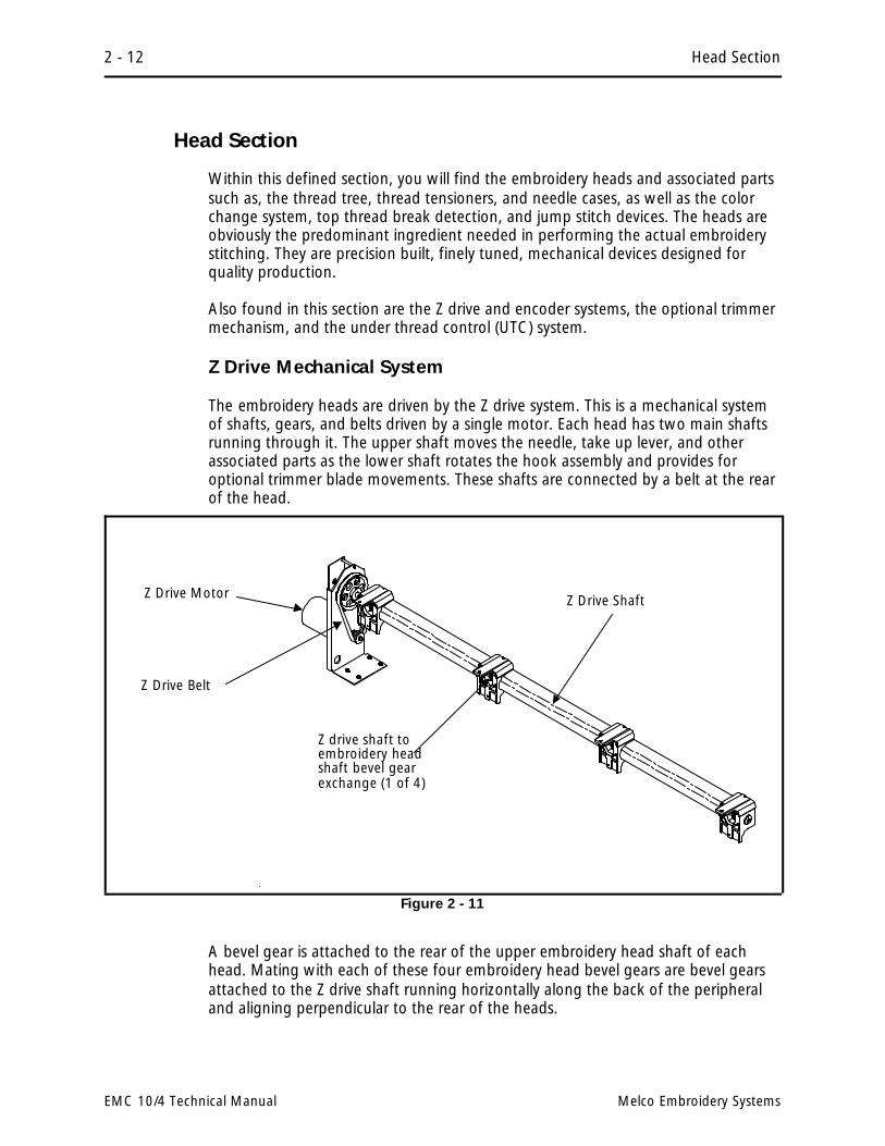
Z Drive Mechanical System
The embroidery heads are driven by the Z drive system. This is a mechanical systemof shafts, gears, and belts driven by a single motor. Each head has two main shaftsrunning through it. The upper shaft moves the needle, take up lever, and otherassociated parts as the lower shaft rotates the hook assembly and provides foroptional trimmer blade movements. These shafts are connected by a belt at the rearof the head.
A bevel gear is attached to the rear of the upper embroidery head shaft of eachhead. Mating with each of these four embroidery head bevel gears are bevel gearsattached to the Z drive shaft running horizontally along the back of the peripheraland aligning perpendicular to the rear of the heads.
Z drive shaft toembroidery headshaft bevel gearexchange (1 of 4)
Z Drive Motor Z Drive Shaft
Z Drive Belt
Figure 2 - 11
2 - 12 Head Section
EMC 10/4 Technical Manual Melco Embroidery Systems
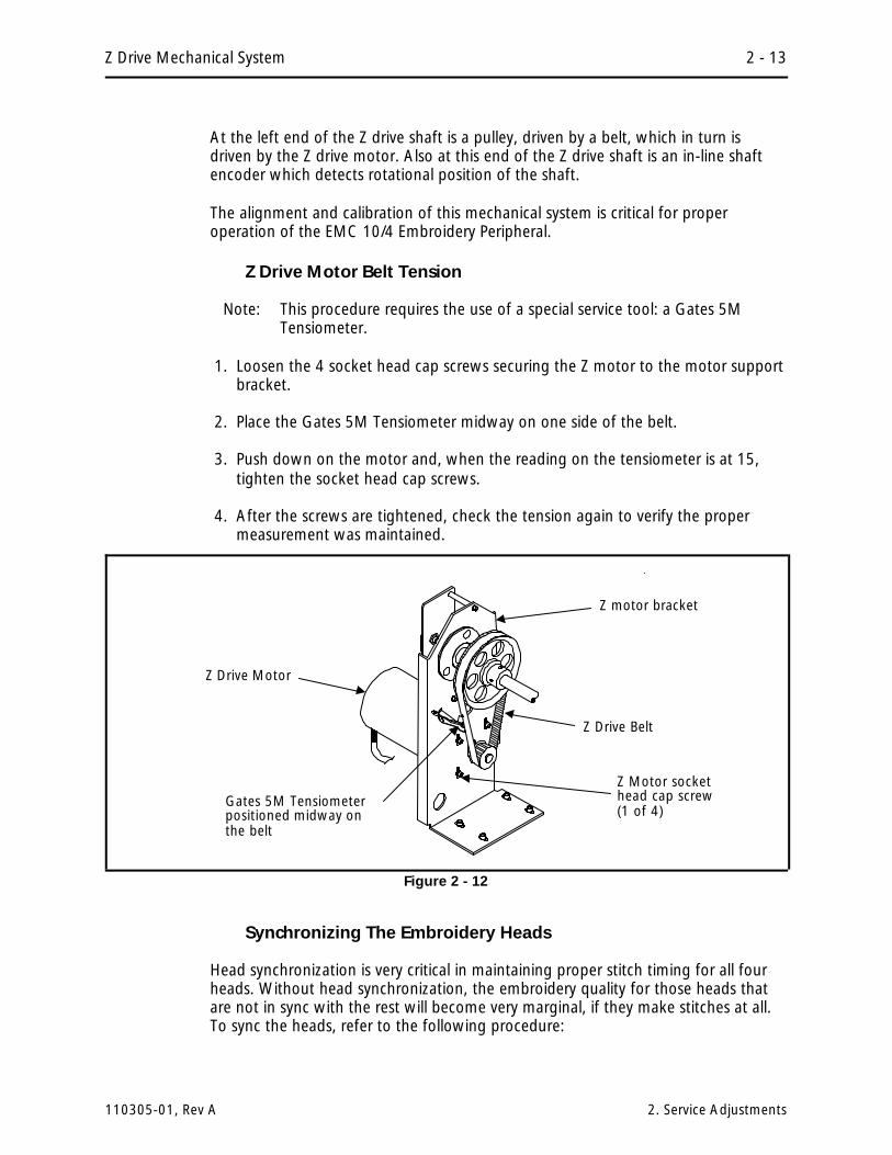
At the left end of the Z drive shaft is a pulley, driven by a belt, which in turn isdriven by the Z drive motor. Also at this end of the Z drive shaft is an in-line shaftencoder which detects rotational position of the shaft.
The alignment and calibration of this mechanical system is critical for properoperation of the EMC 10/4 Embroidery Peripheral.
Z Drive Motor Belt Tension
Note: This procedure requires the use of a special service tool: a Gates 5MTensiometer.
1. Loosen the 4 socket head cap screws securing the Z motor to the motor supportbracket.
2. Place the Gates 5M Tensiometer midway on one side of the belt.
3. Push down on the motor and, when the reading on the tensiometer is at 15,tighten the socket head cap screws.
4. After the screws are tightened, check the tension again to verify the propermeasurement was maintained.
Synchronizing The Embroidery Heads
Head synchronization is very critical in maintaining proper stitch timing for all fourheads. Without head synchronization, the embroidery quality for those heads thatare not in sync with the rest will become very marginal, if they make stitches at all.To sync the heads, refer to the following procedure:
Z Motor sockethead cap screw(1 of 4)
Z Drive Motor
Gates 5M Tensiometerpositioned midway onthe belt
Z Drive Belt
Z motor bracket
Figure 2 - 12
Z Drive Mechanical System 2 - 13
110305-01, Rev A 2. Service Adjustments

1. Remove the #4, and then the #5 rear covers.
2. With the 5 mm hex wrench, rotate the Z drive shaft to the HU position on thedisk at the right end of the Z drive shaft (see Figure 2-13).
3. Turn ON the peripheral and ensure the Z encoder is at the headup position withthe Z drive shaft at HU. (The third LED on the CPU should come ON within +/- 3degrees of rotation around the HU mechanical position of the Z drive shaft.)
4. Perform the Z Shaft Encoder Calibration procedure in this section of the manualif the previous step is not met.
5. When the Z drive shaft and Z shaft encoder are set at the HU position, check thathead #4 is set to the mechanical headup position by installing the headupfixture as described in the Z Shaft Encoder Calibration procedure.
Head #4 must be at its mechanical headup position when the Z drive shaft is at HUand the Z shaft encoder is indicating the headup signal (third LED on CPU).
6. To adjust head #4 to its mechanical headup position, you must have the #5 rearcover removed. For all other heads, you must remove the shroud over the Zdrive shaft section just to the right of the head as you would view it from therear.
NOTE: It remains IMPORTANT to insure that the Z drive shaft stays at the HUposition during this procedure.
Head TimingDisk at theright end ofthe Z Shaft
Socket HeadCap Screwfor 5 mm hexwrench
disk positionindicator
Figure 2 - 13
2 - 14 Head Section
EMC 10/4 Technical Manual Melco Embroidery Systems

7. Loosen the socket head cap screw in the locking collar of the bevel gear on the Zdrive shaft associated with the embroidery head (see Figure 2-14). This willloosen the grasp of the Z drive shaft on the head.
8. Rotate the embroidery head upper shaft (not the Z drive shaft) until the headupalignment tool is installed at the head’s mechanical headup position.
9. Refer to the section on gear mesh on the following page and retighten thelocking collar of the bevel gear on the Z drive shaft loosened in Step 7. This willsecure the head position.
IMPORTANT! Anytime an embroidery head is re-synchronized, you must checkand adjust the hook timing (if needed) on that head. Refer to the hook timingprocedure in the EMC 10/4 Operation Manual.
Shaft Drive Gear Mesh
Engaging the bevel gears on the Z drive shaft and the mating bevel gear on each ofthe 4 embroidery heads must be a sound mechanical union. The couplingrelationship between these gears is called the gear mesh.
The gear mesh must be tight enough to avoid excess "backlash" between thegears, while not binding (approximately .003 to .005 inch gear spacing).
When adjusted properly, you should be able to "feel" the free movement betweenthe mating gears, while you may not be able to "see" the movement.
socket headcap screw
LockingCollar
TOP, REAR of Head (gear boxcover removed)
Z Drive Shaft(shroud removed)
Z ShaftBevel Gear
Z Shaft LeftShroud
Figure 2 - 14
Z Drive Mechanical System 2 - 15
110305-01, Rev A 2. Service Adjustments

Z Encoder System Introduction
The ability to place stitches precisely at high speed is dependent on the accurateoperation of the electronics and electromechanical assemblies. The "key" to this isthe Z encoder. The information provided to the CPU and 4 axis driver by the Zencoder is the basis for all the embroidery head activity.
The Z Encoder is a two channel quadrature output with index pulse. If you send theoutput to an oscilloscope you will see two square wave signals, one slightly aheadof the other. You will also see a third signal, the index pulse. The CPU interpretsthese signals to determine position, speed, and headup.
The CPU uses this information to determine when to move the beam, when to stopthe head for a color change, when setting home position is allowed, how fast thehead is running, how many stitches have been embroidered, etc.
It is important for the technician to understand that the peripheral operationalsoftware handles the motor control circuitry differently when the Z axis is runningthan it does when the Z axis is stopped. When running, the motor control circuitryallows the X,Y, and Z axis motors only minute errors in rotation. Any error greaterthan the allowed error will cause the motor to be driven to eliminate the error.When the peripheral is stopped however, the software that controls the Z motorallows a larger "window" of error. The purpose of this window is to keep themotors from oscillating around the null, hunting for absolute position.
The third LED on the CPU, can be used by the technician to see if the CPU is in factreceiving a headup (or mark) pulse from the encoder (indicating that the encoderand associated cables are functional). It should be noted however, that "theheadup LED does NOT have to be lit when the peripheral is stopped, and the LEDCANNOT be used to make a determination of the Z encoder alignment status." Ifused in conjunction with the proper headup tool, the LED can be used to see if theheadup pulse is triggering early or late as compared to absolute mechanical headup.
The use of the procedures described in the following pages will result in the mostproper, accurate alignment and repair of the Z encoder system that is possible andor feasible for use in the field by a technician.
It can be seen that the proper alignment of the Z encoder can result in maintainingembroidery quality and proper machine operation. Slight Z encoder misalignmentcan cause many kinds of erratic operation and/or intermittent thread breaks. Alarger misalignment can be the cause of equipment damage and subsequentelectronic or mechanical failures. The careful application of the Z encoderprocedures by a factory trained technician will result in a machine that will operatecorrectly and reliably.
2 - 16 Head Section
EMC 10/4 Technical Manual Melco Embroidery Systems

Z Encoder Inspection
"FACTORY SERVICE ADVISED"
This procedure is a guide for determining the condition of the encoder. Ifunauthorized personnel attempt to service this area, the Factory Warranty May BeVoided if the work is improperly performed and damage occurs.
Inspect the Z shaft encoder following the steps below. If the requirements of thisprocess are not met, replace the encoder by following the Shaft Encoder Installationprocedure in Section 3 of this manual.
1. Remove the Rear Cover #4. Then remove the EMI Box Cover to gain access tothe CPU Board. (Refer to specific instructions for removal.)
2. Remove Rear Cover #5, to gain access to the Z Drive System.
3. It is important that the computer not down load a design to the peripheral. Youmay disable the peripheral from the computer by the following method: Locatethe , , and keys on the keyboard of the EMC 10/4 EmbroideryPeripheral.
4. Turn ON the peripheral power, and within 5 seconds, press and hold the , , and keys together.
5. Hold the keys until the "configuration mode" is initiated and the peripheralprogram name appears on the display.
Note: Do not perform any other keystrokes while in the configuration mode.
6. Locate the 2 red LEDs and 1 green LED on the outside end at the top of the CPUPCB in the EMI box (see Figure 2-15).
7. Rotate the heads manually in a clockwise direction by inserting the 5 mm hexwrench into the socket head cap screw in the right end of the Z drive shaft ofthe machine (see Figure 2-13).
8. While slowly rotating the heads, check that the third LED (second red one) blinksonce each revolution at the HU or "headup" mark on the disk at the right endof the Z drive shaft.
Third LED (second red one)This is the LED for headup indication
top left sectionof CPU PCB
first red LED
green LED
Figure 2 - 15
Z Encoder Inspection 2 - 17
110305-01, Rev A 2. Service Adjustments

9. Inspect the electrical connectors (encoder cable plug and encoder body) for loosewires, loose fits, and any visual damage. Clean connections and/or replacecomponents as necessary.
If the "test" above fails or is in question, contact your local Melco servicerepresentative for advise. Refer to Section 3 of this manual for the installationprocedure for a new Z shaft encoder.
Z Shaft Encoder Calibration
"FACTORY SERVICE ADVISED"
CAUTION! Failure to properly calibrate the Z shaft encoder after replacing it, maycause damage when attempting to operate the machine.
Note: This procedure requires the use of a special service tool: the Melco 10 needleheadup fixture (p/n 995673-01).
1. Install the Z shaft encoder as described in Section 3 of this manual.
2. With the embroidery peripheral turned OFF, remove the cover #4. Then removethe EMI Box Cover to gain access to the CPU Board. (Refer to specific instructionsfor removal.) This will expose the three LEDs along the top left of the CPU.
Note: To perform this procedure, it is important that the peripheral doesnot "download." To insure this condition remove the network cable (orboot disk if the disk drive option is installed).
3. With the network cable removed (or boot disk not inserted into a disk driveoption), turn ON the embroidery peripheral.
4. Position the Melco 10 needle headup fixture (p/n 995673-01) into the headupalignment hole in the top of head #4, just in front of the thread tree (see Figure2-16).
headup alignmentpin tool
Figure 2 - 16
2 - 18 Head Section
EMC 10/4 Technical Manual Melco Embroidery Systems

5. Locate the third LED in from the end on the top left of the CPU. Most likely thisLED will not be glowing. It is only supposed to glow for a 1 degree durationeach revolution of the Z shaft encoder.
6. Slowly rotate the heads at the 5 mm socket head cap screw in the right end ofthe Z drive shaft until the headup alignment pin tool inserts into the hole in theheadup alignment collar on the Zshaft. This is the "mechanical"headup position for head # 4.
7. Now loosen the encoder couplersocket head cap screws at theleft end of the Z shaft (see Figure2-17) and slowly rotate thecoupling and encoder (encodershaft socket head cap screws arestill tight) in either direction untilthe third LED on the CPU glows.
8. When the third LED is glowing,tighten the Z shaft socket headcap screws on the encodercoupler.
9. Remove the headup alignmentpin tool.
10. Turn the embroidery peripheralOFF and attach the networkcable (or install the boot disk ifthe disk drive option is installed).
11. Turn the embroidery peripheral ON again and allow its program to download.
12. Go to the head timing menu and check that when the heads are brought toheadup, that the third LED on the CPU glows within plus or minus 3 degrees ofrotation.
13. Reinstall all covers removed during this procedure.
Thread Tensioner Check Spring Adjustment
After replacing a thread check spring, install the thread tensioner into the threadtensioner mounting bracket. You must then adjust the tension of the check springagainst the thread break contact. To set this tension:
1. Slightly loosen the set screw in the top of the thread tensioner mounting bracketthat secures the thread tensioner (see Figure 3-20 in Section 3).
Z Shaft
Z shaftsocket headcap screws
encodershaft sockethead capscrew (1 of 2)
Encoder
encodercoupling
Figure 2 - 17
Thread Tensioner Check Spring Adjustment 2 - 19
110305-01, Rev A 2. Service Adjustments

2. Rotate the thread tensioner to the position where the check spring is justtouching the left side of the thread break contact (brass post). See Figure 2-18.
3. Observe the position of the thread tensioner check spring, then continue torotate the thread tensioner clockwise the distance of 2 spokes of the rotatingdisk (see Figure 2-18). This represents 40 degrees rotation.
4. Tighten the set screw in the top of the thread tensioner bracket.
Adjustment Hints
The following is a discussion of embroidery quality issues with respect to the checkspring adjustment:
As you exceed 2 spokes you may start to see deterioration of the tightening of thestitch due to a reduced rotational stroke of the check spring. A certain amount ofstroke distance is required to take up the thread slack and cinch the stitch properly.If the check spring is too tight against the thread break post it will not retract farenough to make that stroke needed for a good tight stitch. False thread breakmessages may also occur with a setting too tight.
If you rotate less than 2 spokes you will begin to lose the force needed to make atight stitch. You may have enough stroke but not enough force to cinch up thestitch tightly. You may also begin to have failure of thread break detection. Youmust have enough rotation to cause the check spring to make a good contact withthe thread break contact post. A poor contact will often not provide the signal tostop embroidering when there is a thread break.
thread breakcontact post
ThreadCheckSpring
thread tensioner (front view)
2 spokesrotation
check springjust touchingthread breakcontact
Figure 2 - 18
1 spoke
rotatingdisk
2 spokes
0 spoke
thread tensioner (side view)
2 - 20 Head Section
EMC 10/4 Technical Manual Melco Embroidery Systems

Cross Roller Bearing Centering
The cross roller bearing must be installed between the embroidery head v-rail andthe needle case v-rail attached to the retainer plate. When these two are slidtogether and the retainer plate is centered on the head, the cross roller bearingmust be centered (equal distance from each end of the rails).
1. With the needle case and retainer plate assembly removed, lay the cross rollerbearing onto the embroidery head v-rail. Orient the bearing with the weldededge down and position it to the right edge of the v-rail.
2. Place the retainer plate assembly onto the cross roller bearing at the right end ofthe embroidery head v-rail. (The needle case should be removed for easieradjustment.)
3. Slide the retainer plate assembly left to the point where the left edge of theretainer plate is aligned with the center of the needle bar guide shaft felt pad(see Figure 2-19).
4. Position the left edge of the cross roller bearing in line with the left edge of theretainer plate and the center of the needle bar guide shaft felt pad. (The secondroller of the cross roller bearing should just be engaging between theembroidery head v-rail and the needle case v-rail.)
5. Slide the retainer plate assembly onto the embroidery head v-rail and cross rollerbearing.
retainer plate
cross roller bearing
embroideryhead v-rail
needle bar guideshaft felt pad
TOP VIEW
Figure 2 - 19
Cross Roller Bearing Centering 2 - 21
110305-01, Rev A 2. Service Adjustments

6. Check that the cross roller bearing is centered in the 2 v-rails by the followingmethod:
a) Center the retainer plate assembly on the embroidery head v-rail.
b) Carefully insert a solid instrument, such as a straight hex wrench, into theopening at one end where the two v-rails join. Insert the instrument untilit contacts the cross roller bearing. Do not force it any further.
c) Mark the position of the instrument at the end of the embroidery headv-rail, when the instrument is inserted to where it contacts the cross rollerbearing.
d) Repeat this on the other side of the v-rails and compare the two marks.They should be very close to the same - within about 3/32 of an inch.
e) Repeat the above procedure for centering the cross roller bearing until thechecking verifies it is within the proper tolerance.
7. Push the retainer plate assembly left and right as far as possible without thebearings coming off the end of the embroidery head v-rail. While moving theretainer plate assembly try to hold the bearings from rotating (one at a time)with your fingers. With a medium amount of pressure, you should be able tostop the bearing rotation.
Both bearings should require the same amount of pressure to prevent rotation orthe cross roller bearing will migrate out of position.
8. If the test in step 7 shows an incorrect adjustment, refer to the next section,Retainer Plate Bearing Adjustment, to make the proper adjustment.
Retainer Plate Bearing Adjustment
Note: This procedure requires the use of a special service tool: the V-Rail Adjustmentfixture (p/n 995675-01). To adjust without the fixture, refer to theAlternate Method at the end of this procedure.
1. Loosen the two socket head cap screws holding the needle case v-rail to theretainer plate assembly as indicated in the figure below.
2. Install the retainer plate assembly with the cross roller bearing centered betweenthe 2 v-rails (see Cross Roller Bearing Centering on the previous page.
3. Install the v-rail adjustment fixture (p/n 995675-01) into the middle front hole ofthe retainer plate assembly as shown in Figure 2-20.
4. Snug the needle case v-rail to the retainer plate assembly very lightly with thesocket head cap screws. Do not overtighten the screws or the fixture will beunable to perform its adjustment properly.
2 - 22 Head Section
EMC 10/4 Technical Manual Melco Embroidery Systems

5. Carefully and slowly rotate the v-rail adjustment fixture (either clockwise orcounter-clockwise) until you feel a slight resistance. The left and right retainerplate bearings should now be snug against the bottom of the embroidery headv-rail.
6. Tighten the socket head cap screws securely and remove the fixture.
7. Push the retainer plate assembly left and right as far as possible without thebearings coming off the end of the embroidery head v-rail. While moving theretainer plate assembly try to hold the bearings from rotating (one at a time)with your fingers. With a medium amount of pressure, you should be able tostop the bearing rotation.
Both bearings should require the same amount of pressure to prevent rotation orthe cross roller bearing will migrate out of position.
8. If required, loosen the socket head cap screws and repeat this process until thebearings are adjusted as described in step 7.
Alternate Method
A1.After steps 1 and 2, set the retainer plate in its approximate location and snugthe two socket head cap screws as described in step 4.
A2.Attach the needle case as described in Section 3 of this manual.
A3.Check the bearing pressure as described in step 7.
A4. If adjustment is needed, place a flat blade screw driver or similar instrument towedge between the needle case side plate and the needle case V-rail.
retainer plateassembly(cross rollerinstalled andcentered)
install v-railadjustmentfixture here
embroideryhead V-rail
retainer platebearing (rightside)
socket headcap screws
v-railadjustmentfixture
retainer platebearing (leftside)
needle caseV-rail
Figure 2 - 20
Retainer Plate Bearing Adjustment 2 - 23
110305-01, Rev A 2. Service Adjustments

A5.Loosen the V-rail sockethead cap screw on theside you are attending.(With the upper needlecase cover off, you canreach the screw throughthe front of the needlecase.)
A6.Lightly pry in this area andretighten the socket headcap screw.
A7.Check the adjustment asdescribed in step 7 andrepeat until it is properlyachieved.
A8.Repeat the procedure forthe bearing on the otherside.
Lower Rail Retainer Adjustment
This adjustment affects the forward and backward movement of the bottom of theneedle case. Do not make the adjustment so tightly that you preload the rollerbearing in the head so it wears prematurely. Do not have so much free play thatthe needle has excessive movement.
pry lightlywith a flatblade screwdriver here
Needle Caseright side plate
needlecaseV-rail
Figure 2 - 21
gap between zeropreload and .002"
lower railretainer
rollerbearing
screw (underlower rail retainer)
needle caselower rail(needle caseremoved toshow detail)NOTE: if trimmer option
installed, grabber partsmust be removed toaccess screw.
front ofhead
Figure 2 - 22
2 - 24 Head Section
EMC 10/4 Technical Manual Melco Embroidery Systems

1. Install the needle case into the lower rail retainer and attach the needle case tothe retainer plate assembly. Refer to Section 3 in this manual on installing theneedle case assembly.
2. Loosen the screw under the lower rail retainer (see Figure 2-22) and push ittoward the rear to remove the play between the retainer and the lower rail ofthe needle case.
Note: If you have the trimmer option, you will have to remove the grabber bladeguide assembly to access the screw.
3. When the gap between the needle case bottom rail and the embroidery headroller bearing (see Figure 2-22) is between zero preload and .002", tighten thescrew under the lower rail retainer.
Jump Stitch Solenoid
If a jump stitch solenoid has been replaced, you may have to perform one or moreof the adjustment procedures below:
NOTE: The needle case must be removed to perform the adjustment procedures inthis section. See Section 3 for needle case removal.
Plunger Positioning
During the jump stitch solenoid replacement procedure in Section 3, you were tocount the number of threads that are showing beyond the solenoid bracket. If thiswas not done, the following procedure will help position the solenoid plungerproperly. There are two plunger positions of concern:
PlungerPosition 1
The jump stitch solenoid must be positioned so that the plunger is close enough toactuate the needle bar driver reciprocator when the solenoid is engaged (energized).
PlungerPosition 2
The plunger also must not be contacting the reciprocator during normalembroidery, when the solenoid is relaxed or not energized.
A typical dimension for the gap between the relaxed solenoid plunger and needlebar driver reciprocator (see Figure 2-23) is approximately 0.015 to 0.045 inches(0.4 to 1.1 mm).
To obtain this gap, loosen the locking nut on the solenoid and rotate the solenoidinside the bracket until the gap is proper. Tighten the locking nut.
Jump Stitch Solenoid 2 - 25
110305-01, Rev A 2. Service Adjustments

Bracket Positioning
When attaching the jump stitch solenoid and bracket, it is not only necessary toplace the plunger correctly, but you must also position the assembly in the properforward to backward relationship. There are three concerns in positioning thesolenoid and bracket assembly:
BracketPosition 1
The solenoid and bracket assembly should be far enough forward so the plungerwill cause the reciprocator to rotate enough to release the needle bar during thejump stitch cycle.
BracketPosition 2
The solenoid and bracket assembly must not be so far forward that it causes thereciprocator to rotate to its mechanical rotational limit. This may cause prematurefailure of the reciprocator mechanism.
BracketPosition 3
The solenoid and bracket assembly must not be so far backward that it contacts theembroidery head connecting rod during its mechanical motion.
To position the solenoid and bracket:
1. Put the new solenoid and bracket assembly in place and push it to the back ofthe cutout in the side of the head.
2. Attach it to the embroidery head with the 2 screws removed earlier, then checkthe alignment to be within the above 3 positions. Be sure that the plungercontacts the reciprocator mechanism, that the mechanism works properly, andthat the jump stitch assembly does not contact the embroidery head connectingrod during its mechanical motion.
Needle Bar DriverReciprocator
Jump StitchSolenoid
Gap 0.015"- 0.045" (0.4 - 1.1 mm)
Drawing Not To Scale
locking nut
solenoidbracket
Figure 2 - 23
2 - 26 Head Section
EMC 10/4 Technical Manual Melco Embroidery Systems
3. Attach the solenoid wires to the color change PCB on head #4 or the threadbreak harness connection on the other embroidery heads.
Note: The two wires coming from the solenoid body and connecting at the smallblack plastic connector, can be damaged if they are twisted together.Twisting the wires together will reduce their length and can put unduestress at the connections at both ends. We therefore do not recommendtwisting these wires together. If you must group these wires together,use "cable ties" (plastic straps) these are available at most electronicsupply stores.
4. Reinstall all covers removed to change the jump stitch solenoid and testembroider a large letter (6 inch block I, for example) to check the machine forproper jump stitch operation.
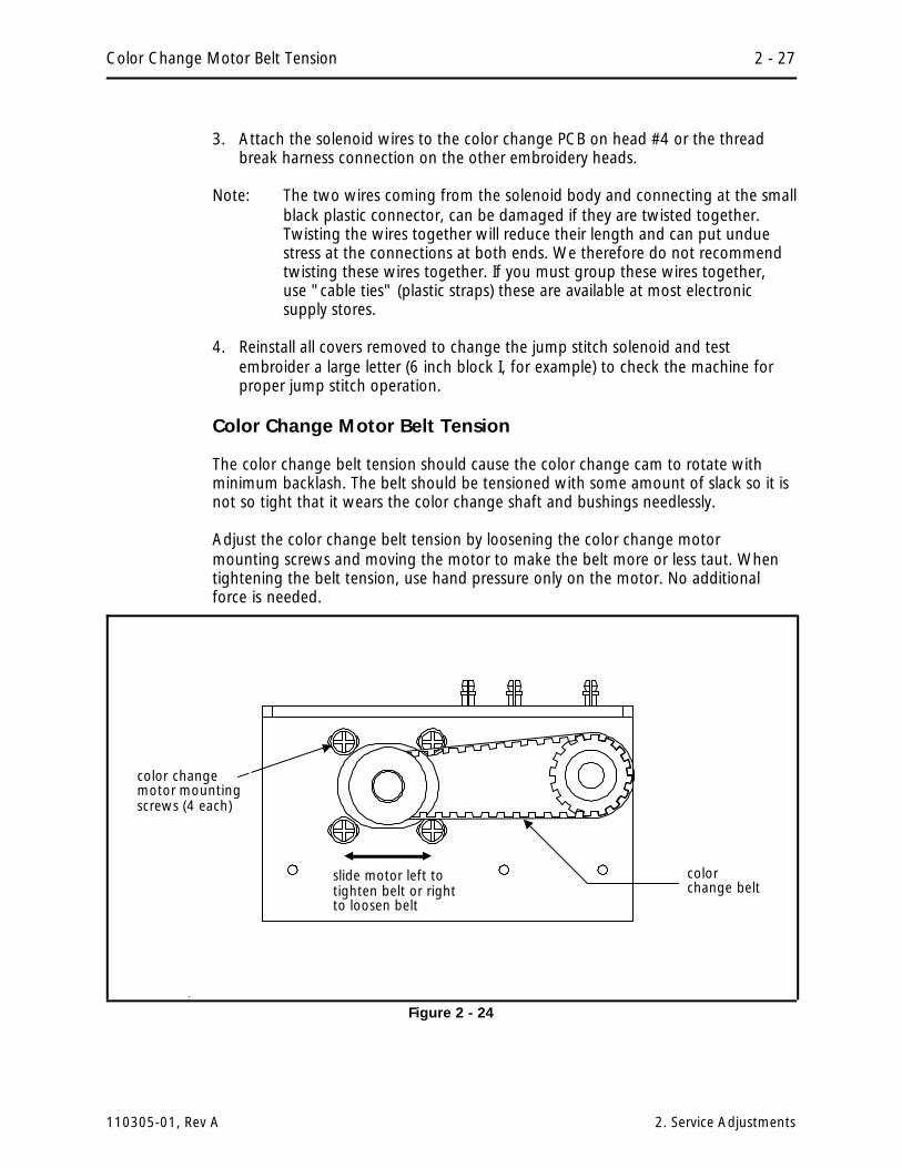
Color Change Motor Belt Tension
The color change belt tension should cause the color change cam to rotate withminimum backlash. The belt should be tensioned with some amount of slack so it isnot so tight that it wears the color change shaft and bushings needlessly.
Adjust the color change belt tension by loosening the color change motormounting screws and moving the motor to make the belt more or less taut. Whentightening the belt tension, use hand pressure only on the motor. No additionalforce is needed.
colorchange belt
slide motor left totighten belt or rightto loosen belt
color changemotor mountingscrews (4 each)
Figure 2 - 24
Color Change Motor Belt Tension 2 - 27
110305-01, Rev A 2. Service Adjustments

Thread Break Brush Adjustment
Head #4
The thread break brush must be adjusted to make proper contact with the threadbreak contact posts coming off the rear of the thread tensioner assembly PCB.
1. Put the needle case in any selected needle position.
2. Loosen the thread break brush bracket mounting screws at the color change PCB(see Figure 2-25).
3. Position the thread break brush so it is centered directly under the selectedneedle thread break contact post coming from the thread tensioner assemblyPCB.
4. Tighten the thread break brush bracket mounting screws securely, but notovertighten.
Head #s 1, 2, and 3
The thread break brush must be adjusted to make proper contact with the threadbreak contact posts coming off the rear of the thread tensioner assembly PCB.
1. Put the needle case in any selected needle position.
Thread BreakBrush
Color ChangePCBThread Break Brush
Bracket MountingScrews
Thread BreakContact Post
Figure 2 - 25
2 - 28 Head Section
EMC 10/4 Technical Manual Melco Embroidery Systems

2. Loosen the thread break brush bracket mounting screws at the top of the head(see Figure 2-26).
3. Position the thread break brush so it is centered directly under the selectedneedle thread break contact post coming from the thread tensioner assemblyPCB.
4. Tighten the thread break brush bracket mounting screws securely.
ThreadBreak Brush
Thread BreakContact Post
Thread BreakBrush BracketMounting Screws
Thread BreakBrush Bracket
Figure 2 - 26
Thread Break Brush Adjustment 2 - 29
110305-01, Rev A 2. Service Adjustments

Trimmer Option
The trimmer option for the EMC 10/4 Embroidery Peripheral is assembled andthoroughly tested before the machine is shipped. Although the set up of thetrimmers should not change during normal use, there are a few things to be awareof to prevent problems.
• Dirt, dust, and thread lint debris can build up and prevent the movableknife (in the rotary hook assembly) from actuating correctly. Keep thearea clean and you shouldn’t have a problem. If for some reason you findthat the movable knife is out of adjustment a procedure for adjusting it ispresented in this section.
• Thread birdnesting around the rotary hook, picker, and UTC sensor armcould cause the knife and/or picker, to become misadjusted.
• The trimmers are operated independently on each of the 4 embroideryheads. If the heads are not synchronized to each other, not only will theembroidery quality be effected, but the trimmers are likely to displaymarginal operational characteristics as well.
Sequence of Trim Events
During the trim function, many events occur with a set timing sequence to enablethe trimming action to be successful. The following steps provide you with a verygeneral outline (and sometimes brief descriptions) of the major actions that takeplace during the trim function.
1. While embroidering a design, the trim function is initiated when the embroideryperipheral detects the design code for: a color change, a trim, a set number ofconsecutive jump stitches, or the end of design.
2. The heads will slow to about 100 stitches per minute, which is the speed rangefor the trimming action.
3. The picker engages with the current thread loop as it is being formed in thehook and bobbin area. This process is required to provide the correct length forrestarting the embroidery next time this thread color is used.
4. The movable knife comes forward to the ready state for trimming. During itsforward movement, it separates the top thread from the thread that is loopedaround the hook. It is here where it "selects" the top thread and bobbin threadfor trimming.
5. When the movable knife returns to the "home" position, the selected threadswill be cut between the movable knife and the spring knife.
6. The beam makes two moves that clears the top thread (now called the tail) outof the material.
2 - 30 Head Section
EMC 10/4 Technical Manual Melco Embroidery Systems

7. At approximately the same time the threads are being cut and the beam ismoving to clear the tail, the grabber reaches out from behind the needle areaand "grabs" the tail, pulling it up and back into the Velcro wiper strip.
8. When the trim is complete the peripheral begins embroidering againautomatically.
Trimmer Set Up And Adjustments
The following procedures provide a guide for adjusting various portions of thetrimmer system.
"FACTORY SERVICE ADVISED"
Note: This procedure requires the use of several service tools: a medium screwdriver, a small screw driver, a 3/32" hex wrench, a 1.5 mm hex wrench, a2 mm hex wrench, and a 2.5 mm hex wrench in addition to the 5 mm Zdrive shaft hex wrench.
Note: In addition to the "standard" tools needed above, you will need a torquewrench (0-250 in/lbs) if making adjustments to the "select" position.
CAUTION! If these adjustments are attempted without using the proper proceduresand tools (and without proper training in some cases), machine components maybe damaged and operation of the trimmers may become inconsistent. Failure tocomply with this caution may void the warranty!
Although many adjustments are fairly straight forward, some are not and they arerecommended to be performed by factory trained technical personnel. Theseadjustments are marked: "FACTORY SERVICE ADVISED."
NOTE: Before attempting to adjust any trimmer mechanisms, ensure that theembroidery heads are properly synchronized to each other. Refer to theembroidery head synchronization procedures in this manual for details inthis area.
Z Timeout Errors
An area of concern with the trimmer system is when birdnesting occurs in the hookarea. If a birdnest builds up in the hook area, there is a potential that movable knifemovement may be obstructed and a mechanical slippage or bending may occurwith one or more components of the trimmer system. This is the most probablecause for the trimmer system to create Z timeout errors. When Z timeout errors area result of the trimmer system, there are two general areas that may contribute tothe situation: 1) bent or broken parts in the trimmer cam system, and 2) movableknife select position adjustment.
Trimmer Option 2 - 31
110305-01, Rev A 2. Service Adjustments

Damaged Trimmer Cam or Trimmer Solenoid
To check for a damaged trimmer cam or trimmer solenoid, refer to the followingprocedure:
1. Remove the rear bed cover of the head to expose the trimmer camming area asseen in Figure 2-27.
2. Turn the machine power ON.
3. Go to the HEAD TIMING MENU and press to turn HEAD TIMING ON.
4. Press the and keys simultaneously to go into the "Z pos" mode. On thedisplay you will see: ’Z pos’ followed with a numerical indication in degrees.
5. With the 5 mm hex wrench at the right end of the Z drive shaft, slowly rotateclockwise until the number of degrees indicated in the display reads between280 and 300.
6. Refer to Figure 2-27 and manually engage the trimmer solenoid pin into thetrimmer cam groove by pushing the protruded end of the pin inward with a flatbladed screw driver.
7. Hold the trimmer solenoid pin in as you continue to apply clockwise rotation tothe Z drive shaft. Rotate the shaft at least one full revolution.
Drill hole in rear ofcam. (must be facingnearly straight upwardat embroidery headheadup position) Engage solenoid pin
into cam groove bypushing here with flatbladed screw driver
trimmersolenoid
trimmercam
solenoid pin endshown engagedin cam groove
Figure 2 - 27
2 - 32 Head Section
EMC 10/4 Technical Manual Melco Embroidery Systems

You should not feel any restrictions during the rotation. If you do, you may have adamaged trimmer cam or trimmer solenoid.
NOTE: You may remove the trimmer solenoid for inspection or replacement.However, when the trimmer solenoid mount is moved, the movable knifehome position may become mis-adjusted.
8. Go to the Mechanical Disassembly section of the manual for the procedure toreplace the trimmer solenoid.
9. While the trimmer solenoid is removed, inspect the trimmer cam for damage. Ifthe cam is damaged beyond use, factory service is recommended to replace it.
10. Go to the movable knife home position adjustment procedure after the solenoidis reinstalled.
11. Repeat this procedure to check again for unrestricted cam assembly movement.
Checking "Headup" Position
Before checking/adjusting movable knife "home" or "select" positions, you shouldcheck the cam positions at headup.
1. Remove the embroidery head rear bed cover to expose the trimmer cammingmechanisms shown in Figure 2-27.
WARNING! Keep clear of the moving parts that are exposed during the operationof the next step(s).
2. Go to the HEAD TIMING MENU and press to turn HEAD TIMING ON. Putthe heads to the "headup" position by pressing the key combination.
3. Locate the holes in the rear of the cams (see Figure 2-27) and check that they arefacing nearly straight upward. If the holes are not facing close to straightupward, the select position may require adjustment. Refer to the Select PositionAdjustment section in this chapter for information on recommended factoryservice.
Trimmers Not Trimming Properly
When the trimmers are not providing adequate trim quality, there are three generalareas that may be contributing to the situation: 1) The physical condition of thetrimmer parts, 2) The Movable Knife "home" position, and 3) The Movable Knife"select" position.
Trimmer Option 2 - 33
110305-01, Rev A 2. Service Adjustments

Physical Condition Of Trimmer Parts
ComponentIdentification
Figure 2-28, identifies those components that comprise the trimmer system: thespring knife, movable knife, and the under thread presser. These components arecovered by the front bed plate and the needle plate (see inset in Figure 2-28).Remove the screws holding these covers to gain access to the trimmer area. Youmay test the trimmer adjustments without the covers in place, but they must beinstalled to embroider.
Spring Knife
Poor trimming quality and non trimming may be caused by the condition of thespring knife.
This situation may result if the spring knife is worn or is not parallel to the trimmingaction of the movable knife. Check this condition of the spring knife by inspectingthe marks left on the surface of the movable knife that is under the spring knife. Ifthe marks are more severe in the area that aligns with one edge of the spring knife,the spring knife may need to be replaced. Another way to check this condition is toperform the "ink wipeoff test" as described in the following steps.
1. With the machine turned OFF, disconnect the connecting link from the movableknife drive arm by lifting it from the front pin (see Figure 2-28).
Connecting Link
UnderThreadPresser
SpringKnife
NeedlePlateSupportBracket
Picker(engaged)
Movable KnifeDrive Arm FrontPin
MovableKnife
Rotary Hook and Rotary HookSupport Bracket not shown
Figure 2 - 28 Trimmer Component ID
Front Bed Plate
Needle Plate
bed plateattaching screw(1 of 4)
2 - 34 Head Section
EMC 10/4 Technical Manual Melco Embroidery Systems

2. Pull the movable knife forward with a small hex wrench hooked behind it.
3. With a black marking pen mark the areas of the movable knife as shown in theleft illustration of Figure 2-29.
4. Push the movable knife back under the spring knife to simulate the threadcutting action.
5. Again pull the knife forward and inspect where the marking pen ink has beenwiped off. Refer to the remaining three illustrations in Figure 2-29 to determineif the spring knife has a problem.
The spring knife has no adjustment. You should make no attempt to bend orreshape the spring knife in any way.
The general condition of sharpness of the blade will also affect trimming quality. Itmay be that the spring knife has simply become dull and needs replaced.
Replace the spring knife per the instructions in Section 3 of this manual. Do notattempt to make any adjustment to the spring knife, however, after replacing aspring knife and all the covers and needle plate, it is advised to operate the TRIMIMMEDIATE command several times to allow the spring knife to ’seat’ itself with themovable knife.
You may check the thread cutting ability in much the same way as the ink wipeofftest by performing actual thread cuts at several locations across the cutting rangeof the blade. To do this follow the steps below:
1. With the machine turned OFF, disconnect the connecting link from the movableknife drive arm by lifting it from the front pin (see Figure 2-28).
2. Pull the movable knife forward with a small hex wrench hooked behind it.
ink wipeoff inthis areaSpring Knifetilted left
ink wipeoff inthis areaSpring Knifetilted right
ink wipeoff inthese areasSpring Knife OK
Apply Ink in theseareas of theMovable Knife
Figure 2 - 29 Ink Wipeoff Test
Trimmer Option 2 - 35
110305-01, Rev A 2. Service Adjustments

3. Obtain a piece of upper thread from the tensioner assembly and drape it overthe movable knife (see Figure 2-30).
4. With the thread draped over the movable knife from back to front, gently holdthe thread so there is some slack and then push the knife back until the threadis cut. This cut should be clean, and should not be frayed.
5. Repeat Step 4 with the thread positioned at different locations across cuttingsurface.
6. If the thread is frayed at any location you may need to replace the spring knife,movable knife, or both.
Replace the fixed blade per the instructions in Section 3 of this manual. Do notattempt to make any adjustment to the fixed blade. After replacing a fixed blade, itis advised to operate the TRIM IMMEDIATE command several times to allow thefixed blade to ’seat’ itself with the movable knife.
1. Drape some Threadover the Movable Knifefrom front to back.
2. Push Movable Knifeback with your thumbor forefinger, to cut thethread.
Figure 2 - 30 Checking The Cut
2 - 36 Head Section
EMC 10/4 Technical Manual Melco Embroidery Systems

Under Thread Presser
The under thread presser, shown in Figure 2-31, holds the bobbin thread after atrim. This permits a loop of bobbin thread for the next stitch. While the underthread presser holds the bobbin thread there should only be enough pressureapplied to hold the thread in place under the movable knife. If the under threadpresser is damaged it can cause problems that look like tension troubles. Forexample, if the pressure of the under thread presser against the movable knife istoo much, it may hold the bobbin thread and not allow a loop to be formed, or itmay nick or fray the thread, again making it look like the bobbin tension isincorrect. Another example, would be if the under thread presser is "crumpled"(see Figure 2-31), it does not allow the movable knife to pass under the spring knifecompletely to cut the thread, causing a "no cut" condition. If the under threadpresser is damaged it can cause intermittent long tails of the upper thread.
Checking the under thread presser is done in two parts. First by looking at the partitself to see if there has been any "crumpling" as shown in the bottom left sectionof Figure 2-31. Crumpling is damage caused by the movable knife hitting the underthread presser. If you see visual evidence of any damage, replace the under threadpresser as described in Section 3 of this manual.
Profile when damaged
Profile of good condition
SIDE VIEW
.50"
TOP VIEW
Under ThreadPresser (underspring knife)
Figure 2 - 31 Under Thread Presser
SpringKnife
MovableKnife
Trimmer Option 2 - 37
110305-01, Rev A 2. Service Adjustments

The second part of checking under thread presser is to check if the bobbin thread isin fact being held in place.
1. While the machine is still turned OFF, remove the font bed cover and disconnectthe connecting link from the movable knife drive arm by lifting it from the frontpin (see Figure 2-28.)
2. Pull the movable knife forward with a small hex wrench hooked behind it.
3. Leaving the bobbin case in the rotary hook, pull off some bobbin thread, anddrape it over the movable knife (see Figure 2-30).
4. With the bobbin thread draped over the movable knife from back to front,gently hold the thread so there is some slack and then push the knife back untilthe thread is cut. This cut should be clean, and should not be frayed.
If the thread is frayed you may need to replace the spring knife, movable knife, orboth.
5. The "top" thread should be loose and fall away, because it has no support. The"bottom" thread should be held in place under the movable knife by the underthread presser.
6. If the under thread presser does not provide the required action, replace it andcheck using steps 2 to 4 again.
7. After you are satisfied with the under thread presser action, re-attach theconnecting link and front bed plate (see Figure 2-28).
Movable Knife
Home Position
The movable knife home position is where the knife stops under the spring knifeafter completing a trim cycle. This position is shown in Figure 2-32. Notice thatwhen properly positioned, the part of the rear tip of the movable knife that slopesaway from the top surface is showing in front of the leading edge of the springknife.
To check that the movable knife is at home position, perform these steps:
1. If the front bed plate is not installed, install it now.
2. Turn the machine power ON.
WARNING! Keep clear of the moving parts that are exposed during the operationof the next steps.
3. Set "home" when prompted to set home on the display.
2 - 38 Head Section
EMC 10/4 Technical Manual Melco Embroidery Systems

4. Go to the TRIM MENU and perform a TRIM IMMEDIATE command.
5. The movable knife should be located under the spring knife, positioned as shownin Figure 2-32. If the sloped rear tip of the movable knife is not showing infront of the leading edge of the spring knife, the "home" position needs to beadjusted. DO NOT Adjust if the knife position looks like Figure 2-32.
6. To adjust movable knife home position, loosen the two screws at the connectinglink drive block in the camming section of the trimmer system (see Figure 2-33).
7. By moving the movable knife, position it to the described home position,allowing the connecting link block to reposition on the camming frame.
8. Snug the two connecting link block screws.
WARNING! Keep clear of the moving parts that are exposed during the operationof the next step(s).
9. Perform a TRIM IMMEDIATE command again and check for the correct homeposition.
10. Repeat steps 7, 8, and 9 until the movable knife home position is correct.
11. Tighten the two connecting link block screws when the home position isadjusted correctly.
Movable Knife
Spring Knife
The part of the rear tipof the movable knifethat slopes away fromthe top surface isshowing in front of theleading edge of thespring knife.
Figure 2 - 32 Movable Knife Home Position
Trimmer Option 2 - 39
110305-01, Rev A 2. Service Adjustments

Home Position Sensor
If the movable knife is mechanically adjusted correctly for home position, but the"Trimmer Not Home" message comes ON, the home position sensor needsadjustment. This adjustment is to move the indicator tab (attached near the cam) tothe middle of the photo sensor when the movable knife is at the home position(see Figures 2-32 and 2-33). To make the adjustment:
1. Loosen the two socket head cap screws that hold the indicator.
2. Move the indicator forward or backward the required amount.
3. Retighten the screws.
WARNING! Keep clear of the moving parts that are exposed during the operationof the next step(s).
4. Repeat the TRIM IMMEDIATE cycle and recheck for the message. Repeat theadjustment as needed until the message no longer comes ON after the TRIMIMMEDIATE cycle.
Photo Sensor
Movable Knife"home" positionindicator adjustmentscrews
Indicator Tab
Connecting Link screws foradjusting Movable Knife"home" position
Engage solenoid pininto cam groove bypushing here with flatbladed screw driver
trimmersolenoid
solenoid pin endshown engagedin cam groove
Figure 2 - 33
2 - 40 Head Section
EMC 10/4 Technical Manual Melco Embroidery Systems

Checking Select Position
After adjusting the movable knife home position, you must check for the movableknife "select" position. If adjustment is required it is recommended that Melcofactory-trained personnel be consulted.
1. Replace the standard needle plate on the embroidery head arm (See Figure2-28). Do not install the raised needle plate used with cap frames.
2. Turn the machine power ON.
3. Go to the HEAD TIMING MENU and press to turn HEAD TIMING ON.
4. Press the and keys simultaneously to go into the "Z pos" mode. On thedisplay you will see: ’Z pos’ followed with a numerical indication in degrees.
WARNING! Potential danger exists any time you perform service around a rotatingbelt. Please use caution during the following steps.
5. Remove the rear bed cover of the embroidery head to expose the trimmercamming area as seen in Figure 2-33.
6. With the 5 mm hex wrench at the right end of the Z drive shaft, slowly rotateclockwise until the number of degrees indicated in the display reads between280 and 300.
7. Refer to Figure 2-33 and manually engage the trimmer solenoid pin into thetrimmer cam groove by pushing the protruded end of the pin inward with a flatbladed screw driver.
8. Hold the trimmer solenoid pin in as you continue to apply clockwise rotation tothe Z drive shaft. Rotate the shaft at least one full revolution. Slowly rotate untilthe entire camming apparatus begins to move forward. Typically, this will readsomewhere in the range of 301 to 303 on the numerical display.
9. Before rotating the Z drive shaft any further, place the Melco select positionfixture (p/n 995372-01) into the needle plate hole (see Figure 2-34). If you donot have the fixture, you may use one of several substitute items (such as a 1.5mm bent hex wrench or the butt of a needle).
10. Now continue to slowly rotate the Z drive shaft clockwise until the movableknife just contacts the select position fixture or substitute item (see Figure 2-34).
11. Stop rotation and allow the preload of the movable knife against the fixture torelax.
12. Check the reading of the display to be between 311 and 313 degrees.
Trimmer Option 2 - 41
110305-01, Rev A 2. Service Adjustments
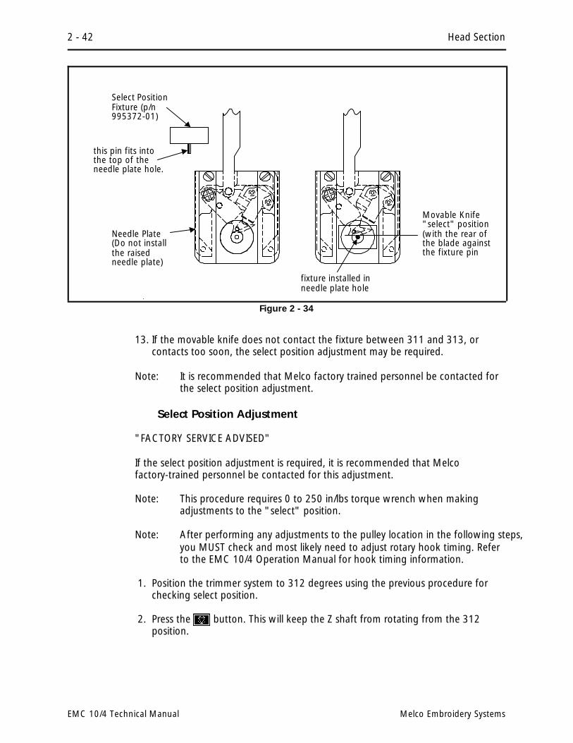
13. If the movable knife does not contact the fixture between 311 and 313, orcontacts too soon, the select position adjustment may be required.
Note: It is recommended that Melco factory trained personnel be contacted forthe select position adjustment.
Select Position Adjustment
"FACTORY SERVICE ADVISED"
If the select position adjustment is required, it is recommended that Melcofactory-trained personnel be contacted for this adjustment.
Note: This procedure requires 0 to 250 in/lbs torque wrench when makingadjustments to the "select" position.
Note: After performing any adjustments to the pulley location in the following steps,you MUST check and most likely need to adjust rotary hook timing. Referto the EMC 10/4 Operation Manual for hook timing information.
1. Position the trimmer system to 312 degrees using the previous procedure forchecking select position.
2. Press the button. This will keep the Z shaft from rotating from the 312position.
Movable Knife"select" position(with the rear ofthe blade againstthe fixture pin
Select PositionFixture (p/n995372-01)
fixture installed inneedle plate hole
Needle Plate(Do not installthe raisedneedle plate)
this pin fits intothe top of theneedle plate hole.
Figure 2 - 34
2 - 42 Head Section
EMC 10/4 Technical Manual Melco Embroidery Systems

3. Loosen the large sockethead cap screw in thelocking collar for the TopBobbin Drive Pulley (seeFigure 2-35) and rotatethe belt and pulleyslightly until the movableknife just contacts theselect position fixture(see Figure 2-34).
4. Stop rotating and hold thebelt and pulley in placewhile you tighten thelarge socket head screwin locking collar to 45inch lbs (6.22 km) oftorque.
5. Remove the select position fixture.
6. Press the key to rotate the head to the headup position.
7. Perform the select position checking procedure again, to check that the movableknife now just contacts the select position fixture in the needle plate holebetween 311 and 313 degrees.
8. Insure all areas loosened to adjust for select position are properly retightenedbefore continuing.
9. Refer to the EMC 10/4 Operation Manual for the procedure to reset hook timing.
Picker Finger Centering
If the cap frame option is not part of your system, you may refer to the followingprocedure to center the picker fingers, should it become necessary.
If your EMC 10/4 has the cap frame option, you must give centering priority to thecap frame driver. When the cap frame driver is centered properly, the picker fingerswill automatically come into proper center alignment. This is because the dovetailclamp for the cap frame driver is fixed to the same bracket as the picker fingers.
1. Loosen the two picker/dovetail bracket screws on the cylinder arm shown inFigure 2-36).
2a. Move the bracket left or right until the picker fingers are centered on the needleshaft.
OR
sockethead capscrew
Top BobbinDrive Pulley
belt
LockingCollar
TOP, REAR of Head
Figure 2 - 35
Trimmer Option 2 - 43
110305-01, Rev A 2. Service Adjustments

2b. With both trimmers and cap frame options on the machine, move the bracket tocenter the installed cap frame driver on the embroidery head arm.
3. Retighten the screws.
Picker Home Position
Note: This procedure requires the use of a special service tool: the Melco pickerset fixture (p/n 995339-01).
1. Install the picker set fixture (as shown in Figure 2-37) to set the picker homeposition.
2. Loosen the set screw inside the swivel pin body shown in Figure 2-36.
3. Move the picker until it rests in the fixture at the picker home position as shownin Figure 2-37.
4. Retighten the set screw.
Picker Height/Depth Position
Note: This procedure requires the use of a special service tool: the Melco picker setfixture (p/n 995339-01).
Front View
CL
The Pickershould becentered onthe BobbinShaft.
Dovetailclamp
Figure 2 - 36
Picker HeightAdjustmentScrews
Adjust Picker Home Positionhere (locking set screw insideswivel pin body)
Picker/dovetail bracket attachment screws (side to side pickerassembly positioning is made by loosening these 2 screws.)
Left Side View
Dovetailclamp
2 - 44 Head Section
EMC 10/4 Technical Manual Melco Embroidery Systems
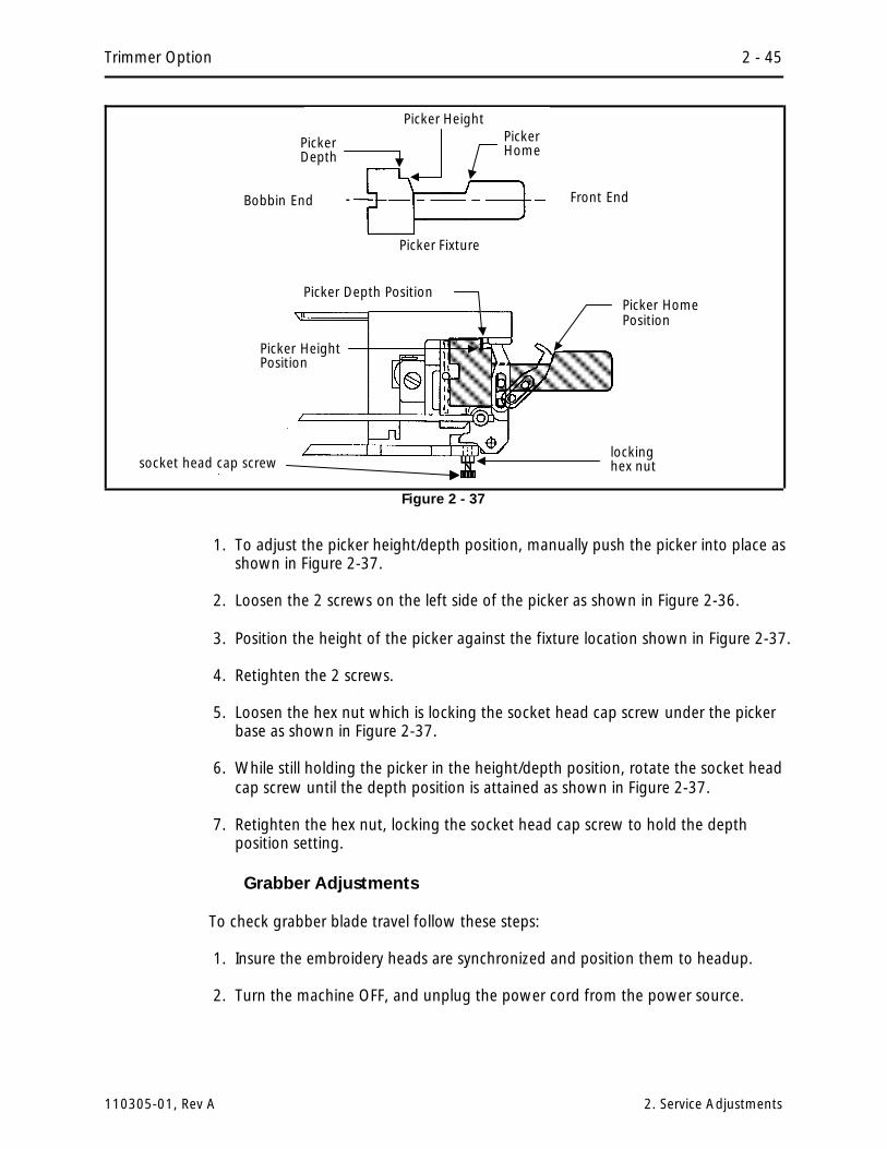
1. To adjust the picker height/depth position, manually push the picker into place asshown in Figure 2-37.
2. Loosen the 2 screws on the left side of the picker as shown in Figure 2-36.
3. Position the height of the picker against the fixture location shown in Figure 2-37.
4. Retighten the 2 screws.
5. Loosen the hex nut which is locking the socket head cap screw under the pickerbase as shown in Figure 2-37.
6. While still holding the picker in the height/depth position, rotate the socket headcap screw until the depth position is attained as shown in Figure 2-37.
7. Retighten the hex nut, locking the socket head cap screw to hold the depthposition setting.
Grabber Adjustments
To check grabber blade travel follow these steps:
1. Insure the embroidery heads are synchronized and position them to headup.
2. Turn the machine OFF, and unplug the power cord from the power source.
socket head cap screwlockinghex nut
Picker Depth PositionPicker HomePosition
Picker HeightPosition
Figure 2 - 37
Picker Fixture
Bobbin End Front End
PickerDepth
PickerHome
Picker Height
Trimmer Option 2 - 45
110305-01, Rev A 2. Service Adjustments
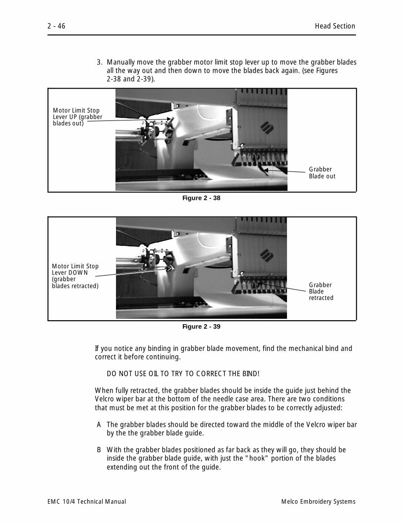
3. Manually move the grabber motor limit stop lever up to move the grabber bladesall the way out and then down to move the blades back again. (see Figures2-38 and 2-39).
If you notice any binding in grabber blade movement, find the mechanical bind andcorrect it before continuing.
DO NOT USE OIL TO TRY TO CORRECT THE BIND!
When fully retracted, the grabber blades should be inside the guide just behind theVelcro wiper bar at the bottom of the needle case area. There are two conditionsthat must be met at this position for the grabber blades to be correctly adjusted:
A The grabber blades should be directed toward the middle of the Velcro wiper barby the the grabber blade guide.
B With the grabber blades positioned as far back as they will go, they should beinside the grabber blade guide, with just the "hook" portion of the bladesextending out the front of the guide.
GrabberBlade out
Motor Limit StopLever UP (grabberblades out)
Figure 2 - 38
GrabberBladeretracted
Motor Limit StopLever DOWN(grabberblades retracted)
Figure 2 - 39
2 - 46 Head Section
EMC 10/4 Technical Manual Melco Embroidery Systems

To Adjust For A:
1. Position the grabber blades as far back as they will go into the grabber bladeguides by manually moving the motor limit stop lever down as shown in Figure2-39.
2. Locate the socket head cap screw in the end of the grabber blade guide (seeFigure 2-50).
3. Loosen the cap screw and move the guide until the grabber blade is directedtoward the middle of the Velcro wiper bar.
4. Tighten the socket head cap screw in the grabber blade guide.
To Adjust For B:
The grabber blade travel is adjusted at the wire swivel where the transition bracketand guide rod enter into the rear of the head. From the transition bracket, the rodis inserted into the wire swivel and held in place with a set screw.
1. Position the grabber blades as far back as they will go into the grabber bladeguides by manually moving the motor limit stop lever down as shown in Figure2-39.
2. Find the small set screw at the right side of the wire swivel in the grabber bladetransition bracket (see Figure 2-51).
3. Loosen the set screw in the wire swivel and position the grabber blade so thehook is protruding between 1.5 and 2.5 mm (.060 - .100 inches) from theguide (see the inset in Figure 2-50).
grabberbladeguide
sockethead capscrew
1 1/2 to2 1/2 mm(.060 - .100inches)
GrabberBladeGuide
grabberbladehookportion
VelcroWiper Bar
grabber bladehook portion
FRONT VIEW
Figure 2 - 40
Trimmer Option 2 - 47
110305-01, Rev A 2. Service Adjustments

4. Tighten the set screw in the wire swivel.
5. Replace all covers after making the grabber adjustments.
Under Thread Control (UTC) Adjustments
It is very important that you follow these instructions any time the rotary hookretaining finger or UTC is loosened or moved. Please follow the instructions in theorder they occur.
Note: The procedures in this section require the following special tools:1) a small straight blade screw driver with a thin blade, and2) the Melco UTC combination gauge part number 009027-01.
Rotary Hook Retaining Finger Positioning
1. Attach the UTC assembly as described earlier in this procedure.
2. Turn the machine ON and go to the Head Timing menu.
3. Position the head to the "Needle Depth" location.
4. Slightly loosen the 2 UTC assembly mounting screws from under the needle platesupport bracket.
Transition Bracketand Guide Rod atrear of head
Grabber Blade
Figure 2 - 41
2 - 48 Head Section
EMC 10/4 Technical Manual Melco Embroidery Systems
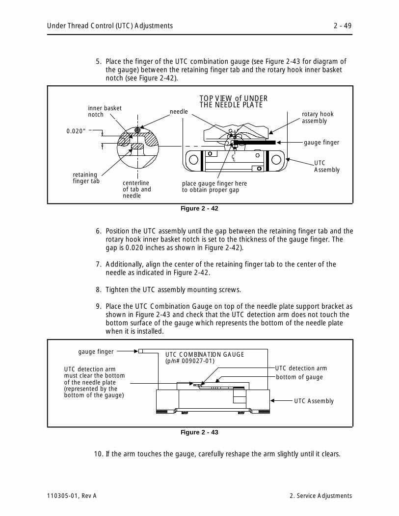
5. Place the finger of the UTC combination gauge (see Figure 2-43 for diagram ofthe gauge) between the retaining finger tab and the rotary hook inner basketnotch (see Figure 2-42).
6. Position the UTC assembly until the gap between the retaining finger tab and therotary hook inner basket notch is set to the thickness of the gauge finger. Thegap is 0.020 inches as shown in Figure 2-42).
7. Additionally, align the center of the retaining finger tab to the center of theneedle as indicated in Figure 2-42.
8. Tighten the UTC assembly mounting screws.
9. Place the UTC Combination Gauge on top of the needle plate support bracket asshown in Figure 2-43 and check that the UTC detection arm does not touch thebottom surface of the gauge which represents the bottom of the needle platewhen it is installed.
10. If the arm touches the gauge, carefully reshape the arm slightly until it clears.
0.020"
rotary hookassembly
retainingfinger tab
inner basketnotch
UTCAssembly
TOP VIEW of UNDERTHE NEEDLE PLATE
centerlineof tab andneedle
C L
place gauge finger hereto obtain proper gap
needle
gauge finger
Figure 2 - 42
UTC detection arm
UTC COMBINATION GAUGE(p/n# 009027-01)
bottom of gauge
gauge finger
UTC detection armmust clear the bottomof the needle plate(represented by thebottom of the gauge)
UTC Assembly
Figure 2 - 43
Under Thread Control (UTC) Adjustments 2 - 49
110305-01, Rev A 2. Service Adjustments

11. Refer to Figure 2-44 and lift the connecting link off of the movable knifeassembly.
12. Check that the movable knife clears the UTC detection arm by physically movingthe knife under the UTC detection arm and back.
13. If the knife touches the arm, reshape the arm slightly until it clears then repeatsteps 9 through 12.
14. Re-attach the connecting link to the pin on the movable knife assembly.
Caution! When installing the covers, be sure not to pinch the UTC Assembly wires!
15. Re-attach the right side rotary hook cover, the needle plate, and the front bedcover.
Sew Test
We now must actually embroider onto properly hooped material to prove theadjustment is proper. A special design named UTCTEST comes on a disk with yourmachine. Load the design into your EDS software or optional disk drive and send itto the sewing peripheral.
The primary purpose of the UTC is to signal when the bobbin thread runs out orbreaks. The UTC has a mechanical arm that is bumped by the bobbin thread duringevery stitch. When the sensor is not bumped for the number of consecutive stitchesthat are set as "Bobbin Count," the machine stops, backs up, and beeps.
If the UTC is too close to the needle, it may not react reliably in detecting theabsence of bobbin thread. If the UTC is too far away from the needle, it may falselyindicate that the machine is out of bobbin thread when it indeed has bobbin thread.
movable knife
UTC detection arm
connectinglink
lift connectinglink here
Figure 2 - 44
2 - 50 Head Section
EMC 10/4 Technical Manual Melco Embroidery Systems

Additionally, if the bobbin tension is set too loose, it may also falsely indicate thatthe machine is out of bobbin thread when it has bobbin thread.
Preliminary Checks
The following must be checked before performing the embroidering:
1. Check that the bobbin tension is within the proper adjustment specifications asdescribed in the operation manual.
2. Verify that the BOB. COUNT in the BOBBIN MENU is set to 5.
Perform The Test
During the embroidering:
A)Check that the UTC detects an absence of bobbin thread when you run out ofbobbin thread and displays the CHECK BOBBIN message.
1. Test for this by wrapping a foot or so of thread around an empty bobbin.
2. Embroider the test design until the thread is completely used.
3. Repeat steps 1 and 2 until the bobbin runs out at least once in bothdirections of diagonal stitching in the test design.
4. If the sensor does not detect when the bobbin runs out of thread, slightlyloosen the UTC sensor body at the screws shown in Figure 2-45, and atthe slotted screw hole (left side) move the sensor a very small amountaway from the needle. Re-tighten the screws.
UTC sensorbody screws
slottedscrew hole
UTCsensor body
VIEW from UNDER theUTC ASSEMBLY(assembly shown removed fromneedle plate support bracket,but is actually attached duringthis adjustment)
Figure 45
Sew Test 2 - 51
110305-01, Rev A 2. Service Adjustments

B) Check that the UTC does not falsely signal the CHECK BOBBIN message whenthread is still on the bobbin.
1. Test for this by simply sewing with the test design. For reliable results,embroider the design for at least 5 minutes, or about 4000 stitches at750 stitches per minute.
2. If you get false CHECK BOBBIN messages, slightly loosen the UTC sensorbody at the screws shown in Figure 2-45, and at the slotted screw hole(left side) move the sensor a very small amount closer to the needle.Re-tighten the screws.
2 - 52 Head Section
EMC 10/4 Technical Manual Melco Embroidery Systems

3. Mechanical Disassembly
General
This section of the manual provides detailed information for performing partsreplacements that may be required during the life of the product. The proceduresare guidelines for performing repair maintenance; and must be used by personnelpracticing good maintenance and repair technique. Good maintenance techniqueincludes, but is not limited to, adhering to all precautions and safety considerationswhen working on the unit; and using the correct tools for the job being performed.
With certain areas in this section it is recommended that the procedure beperformed by a factory trained technician. This reference is indicated by stating"FACTORY SERVICE ADVISED" at the start of the procedure.
WARNING! Failure to practice good maintenance and repair technique may resultin injury to personnel performing the work, and damage to the equipment!
NOTE: The System Warranty is exclusive of, and may be VOID if, poor maintenancepractices have caused damage to the equipment.
Static Electricity / Grounding Strap Use
Any time work is performed inside the covered areas of the embroidery peripheral,it is recommended that a static grounding strap be used.
The grounding strap must be connected in the proper manner to insure the staticcharge on the persons body is neutralized to the chassis ground level of theembroidery peripheral when working in the electronic areas under the covers.
When working inside the controller section (EMI box) of the EMC 10/4, a goodposition for attaching the grounding strap is on the EMI box cover flange (seeFigure 3-1). After removing the EMI box cover, locate the flange around the top ofthe EMI box that holds the nuts for mounting the EMI cover. This box is efficientlygrounded and the flange is easily accessible, to allow the alligator clamp to beattached effectively.
After placing the wristband over your wrist, attach the alligator clamp of thegrounding strap to the EMI box flange (or any other metal which is proven to havechassis electrical ground level).
When working inside the area under the keyboard and display, attach thegrounding strap to any metal which is proven to have chassis electrical groundlevel, but on that side of the machine.
Static Electricity / Grounding Strap Use 3 - 1
110305-01, Rev A 3. Mechanical Disassembly
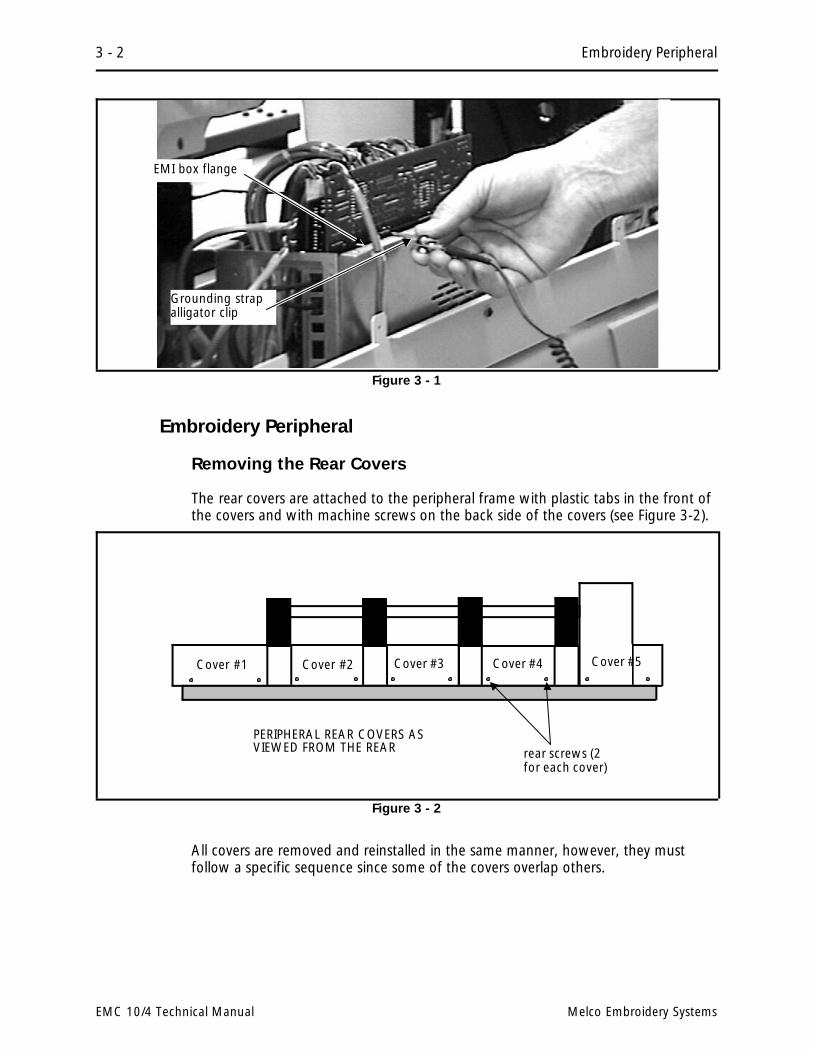
Embroidery Peripheral
Removing the Rear Covers
The rear covers are attached to the peripheral frame with plastic tabs in the front ofthe covers and with machine screws on the back side of the covers (see Figure 3-2).
All covers are removed and reinstalled in the same manner, however, they mustfollow a specific sequence since some of the covers overlap others.
Grounding strapalligator clip
EMI box flange
Figure 3 - 1
Cover #3 Cover #4Cover #2Cover #1
PERIPHERAL REAR COVERS ASVIEWED FROM THE REAR
Cover #5
rear screws (2for each cover)
Figure 3 - 2
3 - 2 Embroidery Peripheral
EMC 10/4 Technical Manual Melco Embroidery Systems

Controller Section Rear Cover #4
Rear cover #4 covers the Controller Section which houses the EMI (Electro-MagneticInterference) box and its printed circuit boards. As with other covers, it is attachedwith screws at the rear and tabs on the front. Cover #4 overlaps covers #3 and #5,and is the first of the 5 covers to be removed and becomes the last cover installed.
After removing cover #4 you will remove cover #5, which covers the Z motor andencoder area; then remove covers #3, #2, and then #1 in that order in the otherdirection. (Refer to Figure 3-2 for an illustration of the covers and theirremoval/installation sequence.
Removing the Tensioner Covers
There are several covers attached around the keyboard, embroidery head tensionerbrackets, and needle case assemblies. Refer to Figure 3-3 and the followingprocedures for removing any and all of these covers.
1. To remove the long cover from the rear of the tensioner brackets on embroideryheads #1, #2, and #3, remove the 2 screws (a) and 7 screws (b). Remove therear tensioner cover out of place carefully, using the following sub-steps:
a) Slide the cover to the left under the left end tensioner cover.
b) Lift the right end back to clear the right end tensioner cover.
c) Slide the rear cover out to the right side.
head #4
Keyboardand cover
.e
.e
.e .d
.d
.d
.d
.d
.d
.d
.d
.c .c .c .c .c .c
.b.b.b.a
.b.b.b.a .
.f
.f
.f
.b
head #2 head #3 head #1
Left endtensioner cover
right endtensioner cover
rear tensionercover
upper frontcover (2 ea)
lower frontcover (3 ea)
.d
.d
.d
.d
Figure 3 - 3
Removing the Tensioner Covers 3 - 3
110305-01, Rev A 3. Mechanical Disassembly

2. To remove any or all of the lower front covers (between needle cases), removethe 2 screws (c) for each cover. Pull down slightly on the cover to remove thepin in the top of the cover from the grommet in the bottom of the upper frontcover (between the tensioner brackets), then carefully remove the lower frontcover from the area.
3. To remove the upper front covers or the keyboard and cover from between thetensioner brackets, you must first remove the lower front cover associated withthe upper front cover you wish to remove. Next, disconnect all associatedharness connections with the cover you are removing. Then, remove the screws(b) and screws (d) associated with the upper front cover and remove the covercarefully. Use care not to damage any components or cables.
4. To remove the left end tensioner cover, loosen the 2 screws (a) and remove the 3screws (e). Slide the cover to the left slightly to remove it from the loosenedscrews (a) and carefully remove the cover.
5. To remove the right end tensioner cover, remove the 1 screw (b) holding the reartensioner cover and remove the 3 screws (f). Remove the right end tensionercover carefully.
3 - 4 Embroidery Peripheral
EMC 10/4 Technical Manual Melco Embroidery Systems

Controller Section
Caution: When the EMI box cover is removed, three printed circuit boards areexposed. These are the CPU, the trimmer interface board, and the backplane board.DO NOT TOUCH THE BOARDS WITHOUT USING ANTISTATIC PRECAUTIONS.
Caution: Never run the embroidery peripheral without the electronics cover inplace. The cover forms the top of the EMI shield around the boards to reduce RFinterference. Running the equipment without the shield (cover) can be a violationof FCC regulations.
CAUTION! In removing any PCBs from the EMC 10/4, use extreme care inhandling. Portions of the boards are very sensitive to static charges and handlingthem must be done using a static grounding strap as instructed in specificprocedures in this manual.
EMI Box Cover Removal
1. Turn OFF the power switch to the EMC 10/4 and remove the power cord fromthe power source electrical outlet and the rear of the machine.
2. Remove the #4 rear cover of the embroidery peripheral as described in a previousprocedure.
3. Loosen the 6 screws on the top of the EMI box cover (see Figure 3-4).
4. Carefully lift the cover out of place and set it aside.
EMI BoxCoverscrews
Figure 3 - 4
EMI Box Cover Removal 3 - 5
110305-01, Rev A 3. Mechanical Disassembly

CPU PCB Replacement
1. Turn OFF the power switch to the EMC 10/4 and remove the power cord fromthe power source electrical outlet and the rear of the machine.
2. Remove the controller section rear cover #4 as previously described.
3. Remove the EMI box cover as previously described.
CAUTION! Failure to use a properly installed static grounding strap may causedamage to the electronics in the EMC 10/4.
4. Install a static grounding strap between the EMC 10/4 and the personnelperforming this procedure.
5. Remove the interface cables connected to the CPU PCB at the rear of the EMC10/4.
6. Remove the screw and washer attaching the CPU PCB bracket to the EMI boxside (refer to Figure 3-5).
Top view of EMI Box with the2 upright PCBs installed andmost harnesses removed.
interfacecables
PCB attachingscrews andwashers
CPU PCB
TrimmerInterfaceBoard
REAR OF MACHINE
BackplanePCB
Figure 3 - 5
3 - 6 Controller Section
EMC 10/4 Technical Manual Melco Embroidery Systems

CAUTION! Use care not to drop any hardware into the base of the Controller area.
7. Remove the various ribbon cables from the connectors on the CPU PCB.
8. Grasp the CPU PCB at the top corners of the board and carefully pull the boardup and out of the card edge connectors mounted on the backplane PCB at thebottom of the EMI box. (Use a gentle rocking motion to make it slightly easierto release the board from the connectors.)
CAUTION! Once the CPU PCB is removed from the EMC 10/4, use extreme care inhandling the assembly. Portions of this board are very sensitive to static charges.Any further handling of the CPU PCB must be done with the continued use of thestatic grounding strap still installed as instructed in specific procedures in thismanual.
9. To replace the CPU PCB, perform the previous steps in reverse order.
10. If during this procedure, the CPU has indeed been replaced with a different one,you must "configure" the embroidery peripheral. Refer to Section 1 of thismanual for information regarding the configuration process.
Trimmer Interface Board Replacement
1. Turn OFF the power switch to the EMC 10/4 and remove the power cord fromthe power source electrical outlet and the rear of the machine.
2. Remove the controller section rear cover #4 as previously described.
3. Remove the EMI box cover as previously described.
CAUTION! Failure to use a properly installed static grounding strap may causedamage to the electronics in the EMC 10/4.
4. Install a static grounding strap between the EMC 10/4 and the personnelperforming this procedure.
5. Remove the screw and washer attaching the Trimmer Interface board bracket tothe EMI box side (refer to Figure 3-5).
6. Remove the various cables from the connectors of the Trimmer Interface board.
7. Grasp the Trimmer Interface board at the top corners of the board and carefullypull the board up and out of the card edge connectors mounted on thebackplane PCB at the bottom of the EMI Box. (Use a gentle rocking motion tomake it slightly easier to release the board from the connectors.)
Trimmer Interface Board Replacement 3 - 7
110305-01, Rev A 3. Mechanical Disassembly

CAUTION! Once the Trimmer Interface board is removed from the EMC 10/4, useextreme care in handling it. Portions of this board are very sensitive to staticcharges. Any further handling of the Trimmer Interface board must be done withthe continued use of the static grounding strap still installed as instructed in specificprocedures in this manual.
8. To replace the Trimmer Interface board, perform the previous steps in reverseorder.
Backplane PCB Replacement
The backplane PCB sits on bottom of the controller section, and contains theconnector where both the CPU and trimmer interface PCBs are inserted.
1. To remove and replace the backplane PCB, first remove the controller sectionrear cover #4, the EMI box cover, CPU PCB, and trimmer interface board asearlier described.
2. Disconnect the cables from the backplane PCB, then remove the screws holdingthe PCB to the base of the controller section; and any ground wire attached tothe screws.
3. Lift the PCB out of the controller section.
4. Replace the backplane PCB using the previous steps in reverse.
Keyboard Section
Keyboard/Display Replacement
To remove the keyboard/display assembly from the cover, refer to Figure 3-6 andthe following procedure:
1. Turn OFF the power switch to the EMC 10/4 and remove the power cord fromthe power source electrical outlet and the rear of the machine.
2. Refer to the Tensioner Cover removal section of this manual and remove thelower front cover under the keyboard and between the middle two embroideryhead needle cases.
3. Next, remove the screw from the rear tensioner cover that goes into the top andrear of the keyboard cover.
4. Install a static grounding strap as described in an earlier procedure.
5. Disconnect the keyboard harness connection from the PCB.
6. Remove the ground wire from the rear bottom of the keyboard cover.
3 - 8 Keyboard Section
EMC 10/4 Technical Manual Melco Embroidery Systems

7. Refer to Figure 3-6 inset and remove the zener diode assembly ring terminalfrom the top of the #2 head needle case.
8. Remove the 4 screws holding the keyboard cover to the tensioner brackets of the2 middle embroidery heads and remove the keyboard and cover to a surfacewhich is free of static electricity.
9. Remove the keyboard/display assembly from the cover by removing the 4 screwssecuring the PCB to the standoffs in the cover.
10. Transfer the key caps from the old keyboard PCB to the new keyboard PCB bysimply lifting them off of the keys by using finger pressure only. It isrecommended that this be done one key at a time to avoid errors in key caparrangement on the new keyboard PCB.
11. When the key caps are transferred, reinstall the keyboard/display assembly byreversing the preceding steps.
Refer to the Adjustment Section of this manual for information in adjusting theintensity of the display, if required.
zener diodeassembly fromkeyboard PCB
standoff(1 of 4)
KeyboardAssembly
attaching screwand hardware(1 of 4)
KeyboardCover
ground wire tothe bottom ofkeyboard cover
Figure 3 - 6
Keyboard/Display Replacement 3 - 9
110305-01, Rev A 3. Mechanical Disassembly

Carriage Section
This assembly and its installation to the peripheral requires specific factory toolingand training to maintain the assembly’s parallelism with the rest of the peripheral.Portions of the carriage assembly may be disassembled to replace various partswithout sacrificing the overall orthogonal integrity.
X Drive Belt Replacement
"FACTORY SERVICE ADVISED"
NOTE 1: The carriage assembly must be partially removed to replace the x carriagedrive belt.
NOTE 2: Be advised that a special quick-drying adhesive is required to complete thisprocedure.
1. Turn OFF the embroidery peripheral and unplug the power cord.
2. Remove the table top inserts and the middle table top section.
3. Position the y beam to mid-range of the y axis movement. Position the x carriageslightly left or right of mid-range of the x axis movement.
4. From under the carriage assembly, remove the socket head cap screw thattensions the belt at the end of the clamp on one end of the belt (see Figure 3-7).
5. Next, remove the 2 phillips head screws that secure the x drive belt clamp to thex carriage at the same end as in the previous step.
6. Remove the 4 socket head cap screws from the top of the beam at each of the 2end and one middle support. (This step involves the removal of 12 socket headcap screws in all.)
socket headcap screw
Left Xcarriagesection
X carriage belt
phillips headscrew (2 ea)
belt clamp
Figure 3 - 7
3 - 10 Carriage Section
EMC 10/4 Technical Manual Melco Embroidery Systems

7. Lift the x carriage and y beam off the 3 supports and lay it up side down acrossthe 2 end table top sections.
8. Remove the socket head cap screw and 2 phillips head screws at the remaining xdrive belt clamp.
9. Remove the x drive belt clamp from ONLY ONE END of the old belt. Leaving oneclamp on the old belt will provide you with a guide to work from wheninstalling the first clamp on the new belt.
10. Tape the new x drive belt to the unclamped end of the old belt and pull the newbelt into place around the spline shaft pulley and idler rollers. Remove the oldbelt from the new belt.
11. Using the remaining clamp on the old belt as a guide and referring to Figure3-8, perform the following procedure to attach the clamp removed from theold belt to one end of the new belt.
a) Orient the clamp with the cutout for the belt in the small edge facing you.
b) With the smooth side of one end of the new belt facing the cutout, slidethat end of the belt into the slot in the clamp. The belt teeth will befacing toward the threaded through hole.
c) Position the belt through the clamp far enough to insert the retaining pininto the fold at the end of the belt (see Figure 3-8, A).
d) While holding the pin is place, pull the belt back through the clamp untilthe pin is captured in the pin cutouts on the clamp (see Figure 3-8, B).
x drivebeltclamp
x drivebelt
threadedthroughhole
retainingpin
BA
Figure 3 - 8
X Drive Belt Replacement 3 - 11
110305-01, Rev A 3. Mechanical Disassembly

12. Remove the remaining clamp from the old belt and perform the previousprocedure to attach the clamp to the other end of the new belt.
13. Attach the new x drive belt and clamp to ONLY ONE END of the x carriage byloosely attaching the socket head cap screw and 2 phillips head screws at theremaining x drive belt clamp.
14. Reposition the x carriage and y beam onto the 2 end and one middle y drivesupports and reattach the 4 socket head cap screws from the top of the beamat each of the supports.
15. Attach the other end of the new belt and clamp to the x carriage by looselyattaching the socket head cap screw and 2 phillips head screws at the clamp.
16. Position the 2 socket head cap screws equally into each clamps insuring not tothe tension the belt at this time.
17. Refer to Section 2 of this manual to adjust the tension of the X Carriage DriveBelt.
18. Reattach the table top inserts and the middle table top section.
Y Drive Belt Replacement
"FACTORY SERVICE ADVISED"
This procedure requires a specific adjustment tool (Gates 5M Tensiometer) forproper adjustment.
1. Turn OFF the power switch to the EMC 10/4 and remove the power cord fromthe power source electrical outlet and the rear of the machine.
2. Remove the EMC 10/4 table covers.
3. Loosen the belt tension adjustment screw at the front of the idler pulley bracket.This allows the old belt to become slack for ease in replacement (see Figure 3-9).
Belt TensionAdjustment Screw
Idler Pulley
Figure 3 - 9
3 - 12 Carriage Section
EMC 10/4 Technical Manual Melco Embroidery Systems

4. Remove the two screws, flat washers, and lock washers at the top of the Y-beltbracket. These screws go through the belt and into the belt clamp underneaththe belt to secure the Y drive belt between the two pieces.
Caution: Overtightening the screws in the next step may cause the belt clamp to bedamaged.
5. Place the new belt around the two pulleys and secure both ends of the beltbetween the Y-belt bracket and the belt clamp piece with the two screws andassociated hardware removed in the previous step.
6. Refer to Section 2 of this manual for adjusting the Y drive belt tension.
7. Replace the table covers and test the machine for proper embroidery quality.
screws, andhardwareattachingbelt to clamp
Belt Clamp (underneath)
Y Belt
Y BeltBracket
Figure 3 - 10
Y Drive Belt Replacement 3 - 13
110305-01, Rev A 3. Mechanical Disassembly

Under Carriage Section
X and Y Drive Motors and Belts
The X and Y Drive motors are located below the embroidery heads and table top.
The X motor provides "side to side" motion of the hoop carriage. The Y motorprovides "front to back" movements of the pantograph (Beam).
"FACTORY SERVICE ADVISED" Special tools are required for proper adjustment.
Tools Required: A zero to 40 lbs. spring scale, 12 inch length of strong cord orcable, a set of socket head wrenches.
1. Turn the peripheral OFF and unplug the power cord from the source voltage.
2. Remove the two socket heat screws holding the covers around the X and Y drivemotor pulleys and belts. Remove the covers.
3. Disconnect motor encoder harness connection from of the motor encoderhousing and the motor drive in-line harness connection (see Figure 3-11).
4. Remove the four socket head cap screws attaching the motor to the bracket.
5. Tilt the motor slightly to allow the drive belt to slip off the motor drive pulley andremove the motor from the support bracket.
Y Motor and EncoderHarness Connections(x motor connectionsthe same)
socket headcap screw(4 each permotor)
X MotorBracket
X Motor
Y Motor
Y MotorBracket
DriveBelt
cord orcable
0-40 poundspring scale
Figure 3 - 11
3 - 14 Under Carriage Section
EMC 10/4 Technical Manual Melco Embroidery Systems

6. Loosen the pulley set screws and remove the pulley from the motor shaft.
7. Place the pulley on the new motor shaft and tighten the pulley set screws.
8. Put the new motor in place in the support bracket and slip the drive belt over thepulley. Insure the other end of the drive belt remains on the pulley associatedwith the x or y mechanism.
9. With the existing hardware, attach the motor to the bracket, but DO NOTtighten the four socket head cap screws at this time.
10. Locate a length of strong cord or cable sufficient to loop over the motor pulleywith four to six inches of cable hanging below the motor.
11. Loop this cable around the motor pulley between the belt and the pulley flangenearest the motor body. Tie the ends of the cable together.
12. Position a 0 to 40 lb. spring scale into the cable loop and pull down with thespring scale until the scale reads 30 lbs. With the pull tension still applied withthe spring scale, tighten the attaching socket head cap screws securing themotor to the bracket. (Use the same procedure for either motor.)
13. Reattach the cables and any covers removed during the procedure.
X Y Z Motor Drives
There are three identical XYZ motor drive PCBs located below the embroidery headsand table top. Access to this section is gained by removing the cover in the leftframe support leg.
WARNING! When the cover is removed, and the machine is ON, potential harmfulvoltage and current is exposed.
The capacitors in this section may store fairly high voltage and current for afew moments after power is removed, therefore extreme care is advisedwhen working in this area immediately after removing power.
It is advise that you delay any work in this area for at least one (1) minuteafter removing power, to allow the voltage to "bleed" from the capacitors.
If unauthorized personnel attempt to service this area, the Factory Warranty May BeVoided if the work is improperly performed. To replace one or more of the XYZmotor drives refer to the following steps:
1. Turn the peripheral OFF and disconnect the power source.
X Y Z Motor Drives 3 - 15
110305-01, Rev A 3. Mechanical Disassembly
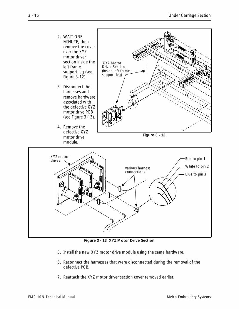
2. WAIT ONEMINUTE, thenremove the coverover the XYZmotor driversection inside theleft framesupport leg (seeFigure 3-12).
3. Disconnect theharnesses andremove hardwareassociated withthe defective XYZmotor drive PCB(see Figure 3-13).
4. Remove thedefective XYZmotor drivemodule.
5. Install the new XYZ motor drive module using the same hardware.
6. Reconnect the harnesses that were disconnected during the removal of thedefective PCB.
7. Reattach the XYZ motor driver section cover removed earlier.
XYZ MotorDriver Section(inside left framesupport leg)
Figure 3 - 12
Red to pin 1
White to pin 2
Blue to pin 3
various harnessconnections
XYZ motordrives
Figure 3 - 13 XYZ Motor Drive Section
3 - 16 Under Carriage Section
EMC 10/4 Technical Manual Melco Embroidery Systems

Power Supply Replacement
The power supply is mounted under the top cover between heads #1 and #2. Toremove the power supply assembly:
1. Turn the peripheral OFF and disconnect the power source.
2. Remove top cover #2 between heads #1 and #2.
3. Disconnect the AC and DC wiring (see Figure 3-14).
4. The power supply is attached into self gripping posts at each of the bottom fourcorners of the power supply box. Pull up on the power supply with a sharp tugto release it from the gripping posts and lift it free of the mounting plate.
5. Reattach the new power supply assembly by placing it in position above the selfgripping posts, then pressing downward to engage the posts firmly into theholes in the power supply.
6. Reattach the AC and DC wiring following the color coded wire information inFigure 3-14.
7. Power up the machine and check the +5VDC and adjust if necessary. Refer tothe +5 Volt Adjustment in Section 2 of this manual.
self gripping posts
POWER SUPPLY (Front View) AC Wiring
DC Wiring
Figure 3 - 14 Power Supply Section
Power Supply Replacement 3 - 17
110305-01, Rev A 3. Mechanical Disassembly

Head Section
General
The Melco embroidery head consists of several physical assemblies. This section ofthe manual describes the removal and replacement of most of the major assembliesof the head.
Arm and Bed Assembly
The arm and bed assembly provides a stable embroidery head platform. All othercomponents of the heads are attached to this assembly.
Inside the arm and bed assemblies are the shafts, belts, and pulleys that drive theneedle and rotary hook. Attached to the outside of the arm and bed assemblies arethe needle cases and color change mechanism (head #4 only), thread treeassembly, and trimmer grabber blade control (head #2 only).
Figure 3 - 15 Head Section
3 - 18 Head Section
EMC 10/4 Technical Manual Melco Embroidery Systems
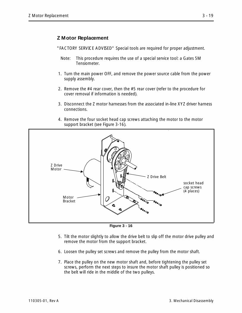
Z Motor Replacement
"FACTORY SERVICE ADVISED" Special tools are required for proper adjustment.
Note: This procedure requires the use of a special service tool: a Gates 5MTensiometer.
1. Turn the main power OFF, and remove the power source cable from the powersupply assembly.
2. Remove the #4 rear cover, then the #5 rear cover (refer to the procedure forcover removal if information is needed).
3. Disconnect the Z motor harnesses from the associated in-line XYZ driver harnessconnections.
4. Remove the four socket head cap screws attaching the motor to the motorsupport bracket (see Figure 3-16).
5. Tilt the motor slightly to allow the drive belt to slip off the motor drive pulley andremove the motor from the support bracket.
6. Loosen the pulley set screws and remove the pulley from the motor shaft.
7. Place the pulley on the new motor shaft and, before tightening the pulley setscrews, perform the next steps to insure the motor shaft pulley is positioned sothe belt will ride in the middle of the two pulleys.
socket headcap screws(4 places)
Z DriveMotor
MotorBracket
Z Drive Belt
Figure 3 - 16
Z Motor Replacement 3 - 19
110305-01, Rev A 3. Mechanical Disassembly

8. Put the new motor in place in the support bracket and slip the drive belt over thepulley. Insure the other end of the drive belt remains on the pulley associatedwith the z drive mechanism.
9. With the existing hardware, attach the motor to the bracket, but DO NOTtighten the four socket head cap screws at this time.
10. Remove the motor pulley set screws and apply Loctite 222 or equivalent screwadhesive, then reinstall the set screws.
11. Position the motor pulley on the motor shaft so the belt will ride squarely onboth pulleys and that the belt will not ride up on the flanges of either pulley.
12. Insure the set screws are in line with the flats of the motor shaft and tighten themotor pulley set screws.
13. Refer to the Z Motor Belt Tensioning procedure in Section 2 of this manual toadjust the belt tension as you secure the motor to the support bracket.
Z Shaft Encoder Installation
The Melco EMC 10/4 Embroidery Peripheral uses a shaft encoder on the end of theZ drive shaft to the left of embroidery head #4. It’s function is to provide theinformation required by the CPU.
"FACTORY SERVICE ADVISED"
CAUTION! If the Z shaft encoder is replaced, DO NOT OPERATE THE EMBROIDERYPERIPHERAL until the new Z shaft encoder is properly calibrated!
To replace the encoder follow these steps:
1. Turn the machine OFF, then disconnect the power from the power source.
2. Remove the #4 rear cover, then the #5 rear cover (refer to the procedure forcover removal if information is needed).
3. Disconnect the Z encoder harness from the z encoder.
4. Using proper antistatic precautions, disconnect the encoder cable from the CPUboard.
5. Loosen the two coupler socket head cap screws that secure the coupling to the Zencoder shaft (see Figure 3-17).
6. Loosen and unthread the jam nut on the encoder shaft.
7. Pull the encoder out of the shaft coupling and encoder mount. Capture the jamnut and washer as the encoder shaft is removed.
3 - 20 Head Section
EMC 10/4 Technical Manual Melco Embroidery Systems

8. Insert the new encoder/shaft into the hole of the encoder mount, place thewasher and then the jam nut onto the encoder shaft as you insert the shaftthrough the mounting plate.
9. Insert the encoder shaft into the shaft coupling.
10. Tighten the jam nut, and then snug the coupling socket head cap screws ontothe encoder shaft.
11. Connect the encoder cable to the CPU board.
CAUTION! If the Z shaft encoder is replaced, DO NOT OPERATE THE EMBROIDERYPERIPHERAL until the new Z shaft encoder is properly calibrated!
12. Calibrate the Z encoder per section 2 of this manual.
Z encoder shaft sockethead cap screws(1 of 2 shown)
encodermount
Jam Nut
Z Encoder Cable
Z Encoder
shaft coupling
Figure 3 - 17
Z Shaft Encoder Installation 3 - 21
110305-01, Rev A 3. Mechanical Disassembly

Thread Tree Assembly Removal
If you need to remove the thread tree for any reason, refer to the followingprocedure:
1. Turn OFF the EMC 10/4 and disconnect the power cord from its power source.
2. Carefully grasp the thread guide tubes individually and remove them frombehind the thread tensioner assembly by pulling on each thread guide tube (seeFigure 3-18).
3. Remove the 3 screws from each of the four embroidery heads that secure thethread tree bracket. Two people are recommended in then lifting off the threadtree assembly.
thread guide tubes
thread tree bracket thread tensionerassembly
3 screws
thread tree
Figure 3 - 18
3 - 22 Head Section
EMC 10/4 Technical Manual Melco Embroidery Systems

Removing the Thread Tensioner Bracket Assembly
The thread tensioner bracket assembly is attached to the top of the needle case. Toremove the tensioner bracket assembly refer to the procedure that follows.
1. Turn OFF the EMC 10/4 and disconnect the power cord from its power source.
2. Remove the side, rear, end, and front covers from each side of the head wherethe tensioner bracket is coming off (refer to cover removal section.
3. Disconnect the thread break harness connection at the rear of the tensionerassembly PCB.
4. Remove the 4 socket head cap screws at the front as shown in Figure 3-19.
5. Carefully lay the tensioner bracket assembly (with the thread tubes still attached)over the top of the thread tree.
The thread guide tubes from the thread tree extend into the tensioner bracket. Ifyou wish to remove the tensioner bracket assembly further from the head, you willneed to remove the thread guide tubes.
6. Remove the thread from the thread guide tubes.
7. Carefully grasp the thread guide tubes individually and remove them from thethread tensioner bracket assembly by pulling on each thread guide tube nearwhere it enters the hole in the thread tensioner bracket.
Thread TensionerAssembly
4 socket headcap screws
Figure 3 - 19
Removing the Thread Tensioner Bracket Assembly 3 - 23
110305-01, Rev A 3. Mechanical Disassembly

Replacing An Individual Thread Tensioner
Each thread tensioner is secured by a set screw against the thread tensioner shaftinside the thread tensioner bracket. The set screw is accessible through a slot at thetop of the tensioner bracket.
1. Using a 2.5 mm hex wrench, loosen the set screw associated with the threadtensioner to be removed (see Figure 3-20).
2. Pull the thread tensioner out of the tensioner bracket.
3. To reinstall the thread tensioner, refer to the next procedure for changing acheck spring.
4. After inserting the thread tensioner into the tensioner bracket, perform thethread tensioner check spring adjustment from Section 2 of this manual. Thisadjustment procedure, not only adjusts the check spring tension, but securesthe thread tensioner in the tensioner bracket by tightening the set screwpreviously loosened in this procedure.
Changing A Check Spring
1. As described previously in this manual, remove the thread tensioner associatedwith the check spring that is being changed.
2. Remove the old check spring and discard it.
ThreadTensionerBracket Thread
Tensioner
set screw, accessiblethrough the slot in thetop of the threadtensioner bracket
ThreadTensionershaft
Figure 3 - 20
3 - 24 Head Section
EMC 10/4 Technical Manual Melco Embroidery Systems

3. Attach the new check spring as follows:
a) Position the check spring around the end of the tensioner shaft as shownin Figure 3-21.
b) Insert the straight length of spring wire that is inside the check spring coilinto the groove cut in the tensioner shaft as shown.
4. While holding the check spring in position, place the thread tensioner into thetensioner bracket. Insure the tensioner shaft seats into the smaller diameterhole in the bracket with the check spring still positioned on the tensioner shaftproperly.
5. After inserting the thread tensioner into the tensioner bracket, perform thethread tensioner check spring adjustment from Section 2 of this manual. Thisadjustment procedure, not only adjusts the check spring tension, but securesthe thread tensioner in the tensioner bracket by tightening the set screwloosened to remove the thread tensioner.
CheckSpring
ThreadTensioner
straight spring wireinto groove intensioner shaft
ThreadTensionershaft
Figure 3 - 21
Changing A Check Spring 3 - 25
110305-01, Rev A 3. Mechanical Disassembly

Replacing A Thread Break Contact Post
1. As described previously in this manual, remove the thread tensioner associatedwith the thread break contact post to be replaced.
2. Remove the thread break contact post (see Figure 3-22) by rotating itcounter-clockwise out of its location in the thread tensioner bracket.
3. Install the new thread break contact post by rotating it clockwise into thetensioner bracket. Secure the post "finger-tight" only.
CAUTION! Use care not to cross thread the post when installing it.
4. Reinstall the thread tensioner and check spring as described in a previousprocedure in this section, then perform check spring adjustment from Section 2of this manual.
Thread Tensioner Bracket
ThreadBreakContactPost
SHOWN WITH #10TENSIONER REMOVED
Figure 3 - 22
3 - 26 Head Section
EMC 10/4 Technical Manual Melco Embroidery Systems

Replacing The Thread Break Wiper Brush
Head #4
1. Remove the two color change covers.
2. Locate the thread break wiper brush attached to the bracket coming from thecolor change PCB (see Figure 3-23).
3. Remove the thread break brush by removing the screw, thread break groundwire, and associated hardware that secures it to the bracket.
4. Replace the brush with the identical part to insure proper operation. Attach thescrew, thread break ground wire, and associated hardware as shown in Figure3.23.
5. Refer to Section 2 of this manual for the adjustment procedure for the threadbreak wiper brush.
thread breakground wire
colorchangePCB
thread breakwiper brushbracket
flat washer
attachingscrew
thread breakwiper brush
star washer
Figure 3 - 23
Replacing The Thread Break Wiper Brush 3 - 27
110305-01, Rev A 3. Mechanical Disassembly

Head #s 1, 2, and 3
1. Remove the covers per the cover removal section.
2. Locate the thread break wiper brush attached to the thread break wiper brushbracket (see Figure 3-24).
3. Remove the thread break brush by removing the screw, thread break groundwire, and associated hardware that secures it to the bracket.
4. Replace the brush with the identical part to insure proper operation. Attach thescrew, thread break ground wire, and associated hardware as shown in Figure3-24.
5. Refer to Section 2 of this manual for the adjustment procedure for the threadbreak wiper brush.
Replacing A Needle Bar
To replace a needle bar, refer to the steps below, then turn to the Needle BarHeight Adjustment Procedure in the EMC 10/4 Operation Manual.
1. Turn ON the EMC 10/4 and bring the embroidery head to the HEADUP position.
2. Turn OFF the EMC 10/4 and disconnect the power cord from its power source.
thread breakground wire
thread breakwiper brushbracket
attachingscrew
thread breakwiper brush
star washer
thread break wiperbrush support bracket
Figure 3 - 24
3 - 28 Head Section
EMC 10/4 Technical Manual Melco Embroidery Systems
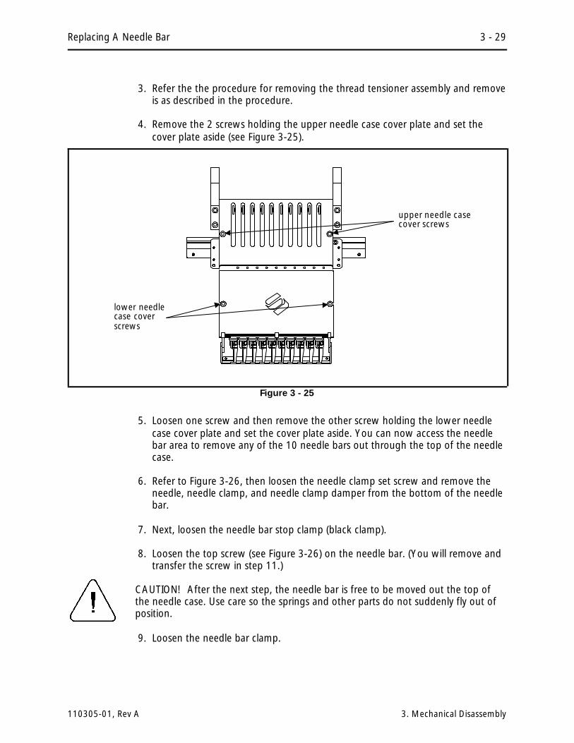
3. Refer the the procedure for removing the thread tensioner assembly and removeis as described in the procedure.
4. Remove the 2 screws holding the upper needle case cover plate and set thecover plate aside (see Figure 3-25).
5. Loosen one screw and then remove the other screw holding the lower needlecase cover plate and set the cover plate aside. You can now access the needlebar area to remove any of the 10 needle bars out through the top of the needlecase.
6. Refer to Figure 3-26, then loosen the needle clamp set screw and remove theneedle, needle clamp, and needle clamp damper from the bottom of the needlebar.
7. Next, loosen the needle bar stop clamp (black clamp).
8. Loosen the top screw (see Figure 3-26) on the needle bar. (You will remove andtransfer the screw in step 11.)
CAUTION! After the next step, the needle bar is free to be moved out the top ofthe needle case. Use care so the springs and other parts do not suddenly fly out ofposition.
9. Loosen the needle bar clamp.
upper needle casecover screws
lower needlecase coverscrews
Figure 3 - 25
Replacing A Needle Bar 3 - 29
110305-01, Rev A 3. Mechanical Disassembly

10. Carefully captureand retain thevarious parts thatbecome released bythe needle bar asyou remove theneedle bar upwardand out the top ofthe needle case.
11. Transfer the screwfrom the top of theold needle bar tothe top of the newneedle bar. ApplyLoctite screwadhesive number222 or equivalent tothe screw if possible.
12. Install a new needlebar by inserting itfrom the top of theneedle case andthrough the variouspieces in the ordershown in Figure3-26.
13. Install a new needleinto the needleclamp and tightenthe needle clampscrew to secure theneedle and capture the needle bar.
14. You may reinstall the upper needle case cover at this time. The lower needlecase cover must, however, remain off to perform the needle bar heightadjustment.
15. After installing a new needle bar, you must adjust the needle bar height. Referto the EMC 10/4 Operation Manual for the adjustment procedure for needlebar height.
16. When the needle bar height has been properly adjusted, reinstall the lowerneedle case cover.
Top Screw -
** Needle Bar Holding Spring -
Needle Bar -
Flat Washer -
Felt Pad -
Upper Needle Case casing -
Needle Case Damper -
Stop Clamp -
Connecting Stud -
** Presser Foot Spring -
Presser Foot upper hole -
Needle Case Damper -
shim -
Felt Pad -
Lower Needle Case casing -
Presser Foot lower hole -
Needle Clamp Damper -
Needle Clamp -
NEEDLE BARINSTALLATIONCROSS SECTION, LEFTSIDE VIEW
** Note: The end of each spring with the smaller coil faces up.
Figure 3 - 26
3 - 30 Head Section
EMC 10/4 Technical Manual Melco Embroidery Systems

Needle Case Removal
It may become necessary to remove the needle case from the front of the head toreplace the needle bar driver, take up lever gear, needle bar reciprocator, or otherassociated parts. Refer to the following steps and Figures 3-27 and 3-28 to removethe needle case from embroidery head.
Head #4
1. Turn ON the EMC 10/4 and bring the head to the HEADUP position.
2. Turn OFF the EMC 10/4 and disconnect the power cord from its power source.
3. Refer to the procedure for removing the thread tensioner assembly and remove itas described in the procedure.
4. Position the needle case to mid-point (needle 5 or 6), then secure the bearingretainer plate assembly from sliding left or right by placing any workableclamping devise onto each end of the V-rail.
5. Remove the 2 screws holding the upper needle case cover plate and set thecover plate aside.
Caution! You must remove the needle position LED sensor interrupter blade toavoid damage to the LEDs on the color change PCB.
6. Remove one and loosen the other of the 2 screws that hold the sensorinterrupter blade to the top of the needle case (see Figure 3-28). Carefully slidethe blade out from between the LEDs under the color change PCB.
7. Hold the needle case securely with one hand while you remove the 4 sockethead cap screws that secure the needle case to the bearing retainer plateassembly near the top of the needle case (see Figure 3-28).
8. Lift the needle case slightly to disengage the lower rail from the lower railretainer coming from the bottom of the embroidery head arm.
9. The needle case will now be free to remove from the the head.
Using care not to damage any components, set the needle case aside.
Head #s 1, 2, and 3
1. Turn ON the EMC 10/4 and bring the head to the HEADUP position.
2. Turn OFF the EMC 10/4 and disconnect the power cord from its power source.
Needle Case Removal 3 - 31
110305-01, Rev A 3. Mechanical Disassembly

upper needle casecover screws
embroideryhead v-rail(left end)
clampingdevices onends of v-rail
bearing retainerplate assembly(left side)
tensionersupportbracket
Figure 3 - 27
Needle Case
Needle Case Lower Rail
Retainer Plate Assembly
socketheadcapscrews(4 each)
Lower Rail Retainer (onembroidery head arm)
Sensor Interrupter Blade
2 screws holdingsensor interrupterblade
Figure 3 - 28
3 - 32 Head Section
EMC 10/4 Technical Manual Melco Embroidery Systems

3. Remove the thread tensioner bracket assembly as described in a previousprocedure.
4. Position the needle case to mid-point (needle 5 or 6), then secure the bearingretainer plate assembly from sliding left or right by placing any workableclamping devise onto each end of the V-rail.
5. Remove the 2 screws holding the upper needle case cover plate and set thecover plate aside.
6. Hold the needle case securely with one hand while you remove the 4 sockethead cap screws that secure the needle case to the bearing retainer plateassembly near the top of the needle case.
7. Lift the needle case slightly to disengage the lower rail from the lower railretainer coming from the bottom of the embroidery head arm.
8. The needle case will now be free to remove from the head.
Using care not to damage any components, set the needle case aside.
Installing Needle Case
To reattach the needle cases refer to Figures 3-27, 3-28, and 3-29 and thefollowing procedure:
Head #4
1. Insure the following conditions are set:
a) The cross roller bearing is properly installed and centered. Refer to Section 2of this manual for adjustment procedure.
b) The retainer plate assembly bearings are properly adjusted. Refer to Section2 of this manual for adjustment procedure.
c) The bearing retainer plate assembly is clamped from moving left or right bya clamping device on each end of the V-rail.
d) The head is at its mechanical "headup" position.
e) The color change cam is in position for a selected needle (preferably needle#5 or #6).
2. Refer to Figure 3-28 and insert the needle case lower rail into the lower railretainer. Insure the grabber blade fits into the grabber bar assembly at thebottom of the needle case.
Installing Needle Case 3 - 33
110305-01, Rev A 3. Mechanical Disassembly

3. Rotate the upper part of the needle case into position on the front of the headas you insure the following alignments:
a) All the take up lever slots are positioned onto the take up lever guide railand the active take up lever gear teeth are engaged with the take uplever drive gear teeth. With the head still in the headup position, insurethe top tooth of the take up lever drive gear engages with the 5th"valley" of the take up lever gears.
b) The needle case color change pins fit into the color change cam properly.
c) The needle case rests solidly and completely on the bearing retainer plateassembly and is positioned to the right so the right side of the needlecase is against the socket head cap screw in the bearing retainer plate asshown in Figure 3-29.
4. Align the 4 through holes on the upper section of the needle case with the 4threaded holes in the bearing retainer plate assembly.
5. Install and tighten the 4 socket head cap screws.
6. Reattach the LED sensor interrupter blade to the top of the needle case.
7. Remove the clamping devises from each end of the V-rail and reinstall all coversthat were removed during the procedure.
socket headcap screw
needle casebearingretainerplate
Figure 3 - 29
3 - 34 Head Section
EMC 10/4 Technical Manual Melco Embroidery Systems

Head #s 1, 2, and 3
1. Insure the following conditions are set:
a) The cross roller bearing is properly installed and centered. Refer to Section 2of this manual for adjustment procedure.
b) The retainer plate assembly bearings are properly adjusted. Refer to Section2 of this manual for adjustment procedure.
c) The bearing retainer plate assembly is clamped from moving left or right bya clamping device on each end of the V-rail.
d) The head is at its mechanical "headup" position.
2. Refer to Figure 3-28 and insert the needle case lower rail into the lower railretainer. Insure the grabber blade fits into the grabber bar assembly at thebottom of the needle case.
3. Rotate the upper part of the needle case into position on the front of the headas you insure the following alignments:
a) All the take up lever slots are positioned onto the take up lever guide railand the active take up lever gear teeth are engaged with the take uplever drive gear teeth. With the embroidery head still in the headupposition, insure the top tooth of the take up lever drive gear engageswith the 5th "valley" of the take up lever gears.
b) The needle case rests solidly and completely on the bearing retainer plateassembly and is positioned to the right so the right side of the needlecase is against the socket head cap screw in the bearing retainer plate asshown in Figure 3-29.
4. Align the 4 through holes on the upper section of the needle case with the 4threaded holes in the bearing retainer plate assembly.
5. Install and tighten the 4 socket head cap screws.
6. Remove the clamping devises from each end of the V-rail and reinstall all coversthat were removed during the procedure.
Installing Needle Case 3 - 35
110305-01, Rev A 3. Mechanical Disassembly

Replacing Needle Case Cross Roller Bearing
Refer to the figures within the needle case removal and installation procedures forthis procedure.
1. Remove the needle case as described previously in this manual.
CAUTION! In the next step, some needle cases may become free to move off thesides of the embroidery heads if bumped. To account for this possibility, you shouldattach a clamping device on the outside ends of the v-rails of any embroidery headsthat are put into this situation.
2. Loosen the clamps holding the needle case linkage shafts and remove the linkageshafts from both sides of the head being worked on.
3. Carefully slide the bearing retainer plate assembly with cross roller bearing offeither end of the V-rail.
4. Position the new cross roller bearing onto the V-rail and install the bearingretainer plate assembly. Refer to the cross roller bearing adjustment procedurein Section 2 of this manual.
5. Check for proper adjustment of the bearing retainer plate assembly bearings byreferring to the adjustment procedure for bearing retainer plate assemblybearings also found in Section 2 of this manual.
6. Reinstall the needle case linkage shafts on both sides of the needle case.
7. Reinstall the needle case that was previously removed.
Needle Centering
8. Insure the #4 embroidery head needle is centered in the needle plate hole whenin the proper color index position for any needle.
Note: The #4 embroidery head needle must be centered before the others.
9. Center the same needle position for each of the other heads by adjusting thelinkage shafts at the various clamps.
3 - 36 Head Section
EMC 10/4 Technical Manual Melco Embroidery Systems

Replacing Reciprocator / Needle Bar Guide Shaft
1. Remove the needle case as described previously in this manual.
2. Loosen the set screw from the left side of the head that secures the needle barguide shaft (see Figure 3-30).
3. Remove the retaining clip from the needle bar guide shaft (see Figure 3-31).
4. Slide the needle bar guide shaft up through the hole in the top of the head toremove it (see Figure 3-31).
Note: If you are only replacing the needle bar guide shaft, proceed to step 8.
5. Remove the reciprocator from the connecting rod by pulling it straight out of thehead (see Figure 3-30). Discard the reciprocator.
6. On the new reciprocator place a drop of machine oil on the reciprocatorconnecting stud (located on the lower back side of the reciprocator).
7. Install the new reciprocator into the head (see Figures 3-30 & 3-31). Make sure itis oriented properly and insert the connecting stud onto the connecting rod.
8. Add two drops of machine oil onto the needle bar guide shaft (or new guideshaft if replacing).
Guide Shaft flat
FRONT VIEW
Set Screw in left side
Connecting Rod (behind theguide shaft)
Needle BarGuide Shaft
Reciprocator
groove in guide shaftfor Retaining Clip
Figure 3 - 30
Replacing Reciprocator / Needle Bar Guide Shaft 3 - 37
110305-01, Rev A 3. Mechanical Disassembly

9. Install the needle bar guide shaft as follows (see Figures 3-30 & 3-31):
a) Insert the guide shaft down through the hole in the top of the head.
b) Insert the guide shaft through the reciprocator.
c) Insert the guide shaft down through the roller bearing.
10. Turn the needle bar guide shaft until the flat near the top faces the left side ofthe head (see Figure 3-30).
11. Pull the needle bar guide shaft down until it seats into the lower hole.
12. Tighten the set screw on the left side of the head to secure the needle bar guideshaft (see Figure 3-30).
13. Reinstall the retaining clip onto the needle bar guide shaft (see Figure 3-31).
hole for removing orinstalling guide shaft
Reciprocator
Roller Bearing
Lower RailRetainer
Retaining Clip
Needle BarGuide Shaft
Figure 3 - 31
3 - 38 Head Section
EMC 10/4 Technical Manual Melco Embroidery Systems
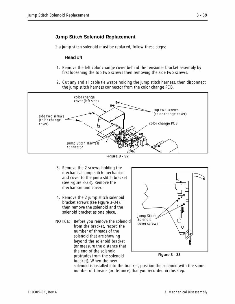
Jump Stitch Solenoid Replacement
If a jump stitch solenoid must be replaced, follow these steps:
Head #4
1. Remove the left color change cover behind the tensioner bracket assembly byfirst loosening the top two screws then removing the side two screws.
2. Cut any and all cable tie wraps holding the jump stitch harness, then disconnectthe jump stitch harness connector from the color change PCB.
3. Remove the 2 screws holding themechanical jump stitch mechanismand cover to the jump stitch bracket(see Figure 3-33). Remove themechanism and cover.
4. Remove the 2 jump stitch solenoidbracket screws (see Figure 3-34),then remove the solenoid and thesolenoid bracket as one piece.
NOTICE: Before you remove the solenoidfrom the bracket, record thenumber of threads of thesolenoid that are showingbeyond the solenoid bracket(or measure the distance thatthe end of the solenoidprotrudes from the solenoidbracket). When the newsolenoid is installed into the bracket, position the solenoid with the samenumber of threads (or distance) that you recorded in this step.
top two screws (color change cover)
side two screws(color changecover)
Jump Stitch Harnessconnector
color change PCB
color changecover (left side)
Figure 3 - 32
Jump StitchSolenoidcover screws
Figure 3 - 33
Jump Stitch Solenoid Replacement 3 - 39
110305-01, Rev A 3. Mechanical Disassembly

5. Loosen the solenoid locking nut then rotate the bracket off of the solenoid.
6. Replace with new solenoid by reversing the previous procedure. Adjust theposition of the solenoid into the solenoid bracket using the "thread counts" ormeasurement you obtained in that procedure (see previous NOTICE).
7. Position the jump stitch bracket back in the head against the mechanical stop.
8. Rotate clockwise with a 5 mm hex wrench in the right end of the Z drive shaft tomove the heads through at least one revolution to check that no mechanicalinterference occurs.
NOTE: During installation the solenoid must be adjusted properly. If you did notadhere to the previous NOTICE, or if for some other reason, theadjustment for the solenoid is not correct, Refer to the Jump StitchAdjustment procedure in Section 2 for the proper adjustments.
Head #s 1, 2, and 3
1. Disconnect the jump stitch harness from the thread break harness at the top ofthe embroidery head arm behind the thread tensioner.
2. Remove the 2 screws holding the mechanical jump stitch mechanism and coverto the jump stitch bracket (see Figure 3-33). Remove the mechanism and cover.
3. Remove the 2 jump stitch solenoid bracket screws (see Figure 3-34), then removethe solenoid and the solenoid bracket.
Jump Stitch Solenoidlocking nut
2 screws of thesolenoid bracket.
record solenoidthreads here
Jump StitchSolenoidcover
Jump StitchSolenoid andBracket
Figure 3 - 34
3 - 40 Head Section
EMC 10/4 Technical Manual Melco Embroidery Systems

NOTICE: Before you remove the solenoid from the bracket, record the number ofthreads of the solenoid that are showing beyond the solenoid bracket (ormeasure the distance that the end of the solenoid protrudes from thesolenoid bracket). When the new solenoid is installed into the bracket,position the solenoid with the same number of threads (or distance) thatyou recorded in this step.
4. Loosen the solenoid locking nut then rotate the bracket off of the solenoid.
5. Replace with new solenoid by reversing the previous procedure. Adjust theposition of the solenoid into the solenoid bracket using the "thread counts" ormeasurement you obtained in that procedure (see previous NOTICE).
6. Position the jump stitch bracket back in the head against the mechanical stop.
7. Rotate clockwise with a 5 mm hex wrench in the right end of the Z drive shaft tomove the heads through at least one revolution to check that no mechanicalinterference occurs.
NOTE: During installation the solenoid must be adjusted properly. If you did notadhere to the previous NOTICE, or if for some other reason, theadjustment for the solenoid is not correct, Refer to the Jump StitchAdjustment procedure in Section 2 for the proper adjustments.
Color Change PCB Replacement
The Color Change PCB controls color change commands from the design andkeyboard, thread break information, the jump stitch solenoid, and the color changemotor. The color change PCB, motor, cam, and wire harnesses are located underthe covers directly behind the embroidery head tensioner assembly. To remove thecolor change PCB refer to the following procedure:
1. Remove the left color change cover behind the tensioner assembly by firstloosening the top two screws then removing the side two screws as shown inFigure 3-35.
2. Remove the two screws in the side of the right color change area cover andremove the cover.
3. Remove the left side tensioner bracket cover.
4. Attach a static grounding strap between yourself and the color change mountingbracket.
5. In clockwise rotation from the middle of the left side of the color change PCB,disconnect the following 5 harnesses: jump stitch solenoid, color change motor,10 needle color change power, 18 color interface, and 10 needle grabber.
Color Change PCB Replacement 3 - 41
110305-01, Rev A 3. Mechanical Disassembly

6. Locate and disconnect the thread break harness from the rear of the threadtensioner PCB.
CAUTION! The Color Change PCB is snapped into place on top of the color changebracket. Be careful not to damage the LED sensors or any other components whenremoving the PCB.
7. Remove the color change PCB by lightly prying up on the board near the 4 catchpins that hold the PCB in place (see Figure 3-36). The color change PCB shouldsimply lift off of the color change housing.
8. Remove the 2 screws securing the thread break contact brush assembly onto theold color change PCB.
9. Attach the thread break brush assembly to the new color change PCB. Transferthe two nylon spacers, or if damaged, install two new spacers between thethread break contact brush bracket and the new color change PCB (see Figure3-36). The screws need only to be snugged slightly, since you will be adjustingthe brush position after the next step.
CAUTION! In the next step, press only on the board, DO NOT press on boardcomponents.
10. To reinstall the color change PCB, align the holes in the board over the catchpins in the color change bracket and lightly press on the board to seat it inplace. DO NOT press on board components.
color changecover (right side)
top two screws (color change cover)
side two screws(color changecover)
color changecover (left side)
color changePCB
side two screws(color changecover)
Figure 3 - 35
3 - 42 Head Section
EMC 10/4 Technical Manual Melco Embroidery Systems

11. Reinstall the thread break harness connection to the thread tensioner PCB, thenrefer to Section 2 of this manual to adjust the thread break contact brushposition.
12. Reinstall the remaining harnesses to the new color change PCB (refer to thefigure on the previous page).
13. Reattach the color change area covers removed during earlier steps in thisprocedure.
Color Change Motor Replacement
To remove the color change motor refer to the following steps:
1. First remove the color change area covers and the left side tensioner bracketcover.
2. Remove the color change PCB as described in previous procedures.
3. Loosen and remove the 4 color change motor mounting screws (see Figure 3-37).
4 catch pinsholding colorchange PCB
Transfer the thread break brushassembly by removing 2 screws.Be sure to transfer the 2 nylonspacers under the bracket to thenew PCB for insulation of thebracket from the PCB circuits. color
change PCB
Figure 3 - 36
Color Change Motor Replacement 3 - 43
110305-01, Rev A 3. Mechanical Disassembly

4. When the motor is loose, pull off the drive belt.
5. Loosen the pulley set screws and remove the motor drive pulley.
6. The motor is now loose and can be removed.
7. Replace the motor and reverse the preceding steps.
8. Refer to the color change motor belt tension adjustment procedure in Section 2of this manual and adjust the belt.
9. Replace all the covers removed to perform this service.
Color Change Cam Assembly Replacement
The color change cam and associated hardware is replaced as an assembly withinthe color change bracket.
1. Remove the left side tensioner bracket cover and the color change area coversbehind the tensioner assembly.
2. Remove the color change PCB as described earlier.
3. Remove the color change motor as described earlier.
4. Remove the 2 screws, then remove the color change bracket (with cam ). Referto Figure 3-38.
4 motormounting screws
color change motor
2 pulley setscrews
motordrivepulley
drive belt
Figure 3 - 37
3 - 44 Head Section
EMC 10/4 Technical Manual Melco Embroidery Systems

5. Lay the color change mount key into the embroidery head key way, then put thenew color change bracket (with the cam) into position.
6. Ensure the needle case is positioned with the needle centered in the needle platehole by moving the color change bracket to obtain the needle centering, thentighten the color change bracket screws. Check and center (if needed) the otherheads by adjusting the needle case linkage shafts between the various needlecases.
7. Reinstall the color change motor and color change PCB as previously describedand reattach the color change area cover behind the tensioner assembly.
Trimmer Assemblies
The thread trimmer assemblies lie in three general areas of the head: in and aboutthe hook and bobbin area, on the arm casting behind the front of the head, and inand throughout the cylinder bed. Replacement procedures for these various partsare found in this section.
Grabber Drive Assembly
FACTORY SERVICE ADVISED!
The grabber drive assembly is mounted to the left side of the # 2 embroidery headarm casting (see Figure 3-39). A factory trained technician is recommended forremoving and installing parts in this section.
color changebracket (with cam)
2 color changebracket screws color change
mount key
Figure 3 - 38
Trimmer Assemblies 3 - 45
110305-01, Rev A 3. Mechanical Disassembly

Grabber Blade
1. Remove the 4 screws and take off the top grabber blade cover.
2. Remove the two button head screws that secure the grabber blade to thegrabber drive assembly where it enters into the embroidery head arm casting(See Figure 3-40).
Figure 3 - 39 Grabber Drive Assembly
2 button head screws securing grabber blade
Grabber Blade
Figure 3 - 40
3 - 46 Head Section
EMC 10/4 Technical Manual Melco Embroidery Systems

3. Remove the 4 screws to free the front grabber blade cover (see Figure 3-41).Slide the grabber blade out of the grabber blade guide (just behind the Velcrowiper bar) as you remove the cover and grabber blade.
4. Reverse order of the previous steps to replace the grabber blade.
When reinstalling the grabber blade, be sure to slide the grabber blade into thefront blade cover and then the grabber blade guide before installing the screws toattach the grabber blade to the grabber drive assembly at the entry into the armcasting.
When tightening the covers, some positioning adjustment may be required toensure smooth blade movement.
topgrabberbladecover
grabber blade guide
front grabber blade cover
the finger ispointing to thegrabber blade
Velcro wiper bar
Figure 3 - 41
Trimmer Assemblies 3 - 47
110305-01, Rev A 3. Mechanical Disassembly

Trimmer Drive Assembly
Trimmer Cam
FACTORY SERVICE ADVISED!
This assembly is mounted under the head in the rear bed. To remove thismechanical assembly requires several steps, including removing the embroideryhead from the frame. A factory trained technician is recommended for removal andinstallation of parts in this area.
Trimmer Solenoid
NOTE; When the trimmer solenoid mount is moved, the movable knife homeposition may become mis-adjusted. Refer to the movable knife homeposition adjustment procedure after the solenoid is reinstalled.
1. Remove the head rear bed cover to gain access to the trimmer drive assembly.
2. Refer to Figure 3-42 and mark the position of the solenoid mount in its track onthe movable frame. This will aid in returning the assembly to its currentposition, helping to keep the movable knife home position as close as possible.
3. Remove the socket head cap screw from the solenoid mount and lift the solenoidand mount out together.
4. Loosen the set screw in the top of the solenoid mount to allow the solenoid tobe rotate out of the mount.
hex nut betweensolenoid and mount
capheadscrew
trimmer solenoid
mark solenoidmount position
solenoid mount
socket head cap screw
opticalswitch
set screw in top ofsolenoid mount
Figure 3 - 42 Trimmer Camming Mechanism
3 - 48 Head Section
EMC 10/4 Technical Manual Melco Embroidery Systems

5. Loosen the hex nut between the the solenoid body and the mount, then rotatethe solenoid assembly out of the mount.
6. Rotate a new solenoid assembly into the mount. Do not tighten the hex nut orset screw in the top of the mount at this time.
7. Reinstall the solenoid and mount to the movable frame and refer to theadjustments section of this manual to adjust for solenoid positioning andmovable knife home position. When the trimmer solenoid and mount arereinstalled you may also need to adjust the home stop screw or adjust thesolenoid mount to achieve proper travel of the solenoid pin into the cam groove.
8. Reinstall the head rear bed cover.
Picker Solenoid Assembly
FACTORY SERVICE ADVISED!
This assembly is mounted at the rear of the trimmer drive assembly in the rear bedof the embroidery head. To remove the solenoid requires among its steps, theremoval of the trimmer drive assembly from the embroidery head.
1. Remove the head rear bed cover to gain access to the trimmer drive assembly.
2. Refer to Figure 3-44 and remove the cap head screw holding the movable knifeconnecting link to the drive block.
3. Remove the four hex bolts holding the trimmer drive assembly into the bed of theembroidery head. Allow the assembly to be lowered from the bottom of the bed.
4. Disconnect the picker link from the picker solenoid plunger by removing the setscrew and swivel clamp that hold them together.
5. Disconnect the home position optical switch and trimmer solenoid in-lineconnectors from the picker solenoid harnessing.
6. Loosen the hex nut that snugs the solenoid to the mounting bracket. Rotate thesolenoid out of the mounting bracket.
7. Reverse the previous procedure to install a new picker solenoid.
8. Refer to Section 2 of this manual for checking and performing the various pickeradjustments.
Trimmer Assemblies 3 - 49
110305-01, Rev A 3. Mechanical Disassembly

Home Position Optical Switch
1. Remove the cap head screw holding the body of the optical switch in position(see Figure 3-42).
2. Carefully manipulate the switch harness through the cutout in the bracket untilyou can access and disconnect the in-line connector.
3. Connect the new optical switch to the in-line connector and place the switch inposition on the bracket.
4. Reconnect the optical switch with the cap head screw.
Picker Assembly
1. Remove the screws holding the needle plate. Remove the needle plate.
2. Disconnect the picker link from the picker base by loosening the set screw insidethe swivel pivot of the picker base (see Figure 3-43).
3. Remove the external retaining ring at right end of the picker base shaft.
4. Slide the picker assembly out of the picker bracket mount.
When re-attaching the picker link to the picker assembly, refer to the alignmentsection of this manual for the alignment procedure for the picker position.
mounting screws
PickerBracketMount
PickerPicker Link
Swivel Pivot
set screw
ExternalRetainingRing
PickerBase andshaft
Figure 3 - 43
3 - 50 Head Section
EMC 10/4 Technical Manual Melco Embroidery Systems

Movable Knife
1. Remove the screws holding the needle plate. Remove the needle plate.
2. Remove the screws holding the front and rear bed covers and remove the covers.
3. Lift the forward end of the connecting link from the pin on the movable knifedrive arm (see Figure 3-44).
4. Push the movable knife all the way back until it stops.
5. Loosen the hex socket screw holding the movable knife to the top of the knifedrive arm.
6. Rotate the movable knife out of the spring knife, then remove the hex socketscrew and the movable knife.
7. Place the new movable knife on the top of the knife drive arm, positioning thealignment hole in the knife over the alignment pin in the arm.
8. Apply Loctite 222 screw adhesive (or equivalent) and install the hex socket screwand snug it with your fingers.
Connecting Link
pin on Movable KnifeDrive Arm
hexsocketscrew
MovableKnife
Spring Knifeand UnderThread Presser
alignmentpin/hole
button head screw
button head screwand spacer betweenblade and presser
Figure 3 - 44
Trimmer Assemblies 3 - 51
110305-01, Rev A 3. Mechanical Disassembly

9. Rotate the knife and arm clockwise until the back side of the knife is restingagainst the left side of the needle plate bracket.
10. Tighten the hex socket screw.
Spring Knife/Under Thread Presser
1. Remove the screws holding the needle plate. Remove the needle plate.
2. Remove the screws holding the front and rear bed covers. Remove the covers.
3. Lift the forward end of the connecting link from the pin on the movable knifedrive arm (see Figure 3-44).
4. Rotate the movable knife forward to remove it from under the spring knife andunder thread presser.
5. Remove the two button head screws from the top of the spring knife.
Note: In the next step it is important to note at which screw hole any spacer mightbe located.
6. Remove the spring knife, the under thread presser, and/or a spacer.
Note 1: A spacer may be placed under one of the screws for leveling at initialinstallation. If reinstalling the old spring knife, you must reinstall thespacer at the same location as it is currently.
Note 2: When installing a new spring knife, disregard the spacer and attach thenew spring knife without using the spacer. Later in the adjustmentprocess you may need a spacer, but you cannot determine it at this time.
7. Replace the required new parts.
Note 1: If the old spring knife is reinstalled and a spacer was under one screw hole,replace the spacer at the same screw location.
Note 2: If a new spring knife is being installed, DO NOT install any spacer.
8. Install and tighten the 2 button head screws.
The only adjustment for the spring knife is for the inclusion of a spacer, if needed).However, after replacing a spring knife, it is advised to operate the TRIMIMMEDIATE command several times to allow the spring knife to "seat" with themovable knife. Then refer to Section 2 of the manual for adjustment information.
3 - 52 Head Section
EMC 10/4 Technical Manual Melco Embroidery Systems

Movable Knife Drive Arm
1. Remove the screws holding the needle plate. Remove the needle plate.
2. Remove the screws holding the front and rear bed covers. Remove the covers.
3. Lift the forward end of the connecting link from the pin on the movable knifedrive arm (see Figure 3-45).
4. Remove the small pan head screw and fixing clip from the bottom of the needleplate bracket.
The clip is held into a slot in the arm shaft by the screw and the combination holdsthe arm shaft in place. Once this clip is removed, the arm shaft is free to be removeout of the top of the needle plate bracket.
small panhead screw
fixing clip
Connecting Link
Needle PlateBracket
Movable Knifedrive arm
Figure 3 - 45
Trimmer Assemblies 3 - 53
110305-01, Rev A 3. Mechanical Disassembly

UTC Replacement
To remove the UTC assembly refer to the steps that follow:
1. With the machine in the head up position, turn the power switch OFF.
2. Remove the table top insert from the machine to access the Hook and UTC area.
3. Remove the needle plate, front bed cover, and right side rotary hook cover toaccess the UTC assembly including the sensor cable and connection to theharnessing in the bed.
4. Disconnect the sensor cable from the harness inside the bed and remove thecable from around the needle plate support bracket (see Figure 3-46).
5. Remove the 2 UTC assembly mounting screws that hold the UTC assembly androtary hook retaining finger to the bottom of the needle plate support bracket(see Figure 3-46).
To attach the UTC assembly, refer to the steps that follow.
6. Connect the sensor cable from the new UTC assembly to the harness inside thebed as indicated in Figure 3-46.
7. Rotate the rotary hook inner basket to position the notch to the top so theretaining finger tab will fit into the notch properly when the UTC assembly isattached.
harness connectioninside the bed
UTC sensor cable(part of UTC assembly)
UTC assemblymounting screws,securing UTC assemblyand rotary hookretaining finger
UTC sensorassembly
needle platesupport bracket
Figure 3 - 46
3 - 54 Head Section
EMC 10/4 Technical Manual Melco Embroidery Systems

8. Place the UTC assembly under the needle plate support bracket as shown inFigure 3-47 and install the 2 UTC assembly mounting screws.
10. Perform the UTC adjustments in Chapter 2 of this manual.
UTC assemblyand rotary hookretaining finger
needle platesupportbracket
UTC assemblymounting screws
Figure 47
UTC Replacement 3 - 55
110305-01, Rev A 3. Mechanical Disassembly

This page intentionally left blank
3 - 56 Head Section
EMC 10/4 Technical Manual Melco Embroidery Systems

#
+5 Volt Power Supplyadjustment 2-10
AAC Voltage Selection 2-9
BBackplane PCB Replacement 3-8
CCheck Spring
adjustment 2-19replacement 3-24
Color Change Cam Replacement 3-44Color Change Motor Belt
tension 2-27Color Change Motor Replacement 3-43Color Change PCB Replacement 3-41Configuration Procedure 1-6Configuring
display language 1-7peripheral program 1-7unit number 1-7
Coversremoving EMI box 3-5removing rear 3-2removing tensioner 3-3
CPU PCB Replacement 3-6Cross Roller Bearing
centering 2-21replacement 3-36
DDisplay Language 1-6Display Screen Intensity 2-2Drive Belt Tensions 2-1
G
Grabber 3-46adjustments 2-45
Grounding Strap Use 3-1
H
Head Synchronizing 2-13
I
Input Voltage Selection 2-9
J
Jump Stitch Solenoidadjustment 2-25replacement 3-39
K
Keyboard/Display Replacement 3-8
L
Lower Rail Retaineradjustment 2-24
MMaintenance Philosophy 1-3Movable Knife 3-51
home position 2-38home position sensor 2-40select position 2-41
Movable Knife Drive Arm 3-53
N
Needle Bar Guide Shaft Replacement 3-37Needle Bar Replacement 3-28Needle Case
installation 3-33removal 3-31
P
Peripheral Program 1-5Picker
height/depth position 2-45home position 2-44
Picker Assemblyhome position switch 3-50
Picker Fingerposition 2-43
Picker Solenoid 3-49Power Supply Replacement 3-17
R
Reciprocator Replacement 3-37Retainer Plate Bearing
adjustment 2-22Rotary Hook
retaining finger positioning 2-49
S
Spring Knife 2-34, 3-52Static Electricity 1-3, 3-1
T
Thread Break Brushadjustment 2-28
Thread Break Contact Postreplacement 3-26
Thread Break Wiper Brushreplacement 3-27
INDEX
EMC 10/4 Technical Manual i

Thread Tensionerreplacement 3-24
Thread Tensioner Bracketremoval 3-23
Thread Tree Assemblyremoval 3-22
Trimmer Cam 3-48Trimmer Interface Board Replacement 3-7Trimmer Solenoid 3-48Trimmer System 2-30, 3-45Trimmers
components 2-34grabber 2-45, 3-45movable knife 2-38, 3-51not trimming 2-33picker finger 2-43setup and adjustment 2-31spring knife 2-34, 3-52under thread presser 2-37, 3-52Z timeout errors 2-31
U
Under Thread Control (UTC)adjustment 2-48detection arm height 2-50hook retaining finger position 2-49replacement 3-54sew test 2-52
Under Thread Presser 2-37, 3-52Unit Number 1-6
W
Warrantyconsiderations 1-3registration 1-1
X
X Drive Beltreplacement 3-10tension 2-3, 2-5
X Drive Motorreplacement 3-14
X Motor Beltreplacement 3-14tension 2-8
XYZ Motor Drives 3-15
YY Drive Belt
replacement 3-12tension 2-7
Y Drive Motorreplacement 3-14
Y Motor Beltreplacement 3-14tension 2-9
ZZ Drive
gear mesh adjustment 2-15Z Drive Mechanical System 2-12Z Drive Motor Belt
tension 2-13Z Encoder
calibration 2-18inspection 2-17installation 3-20
Z Encoder System 2-16Z Motor
replacement 3-19
INDEX
ii EMC 10/4 Technical Manual