Installation, Operation, and Maintenance Manual for … · EMC 10/12 Installation, Operation, and...
84
A Saurer Group Company Part Number 110268-01, Revision C Installation, Operation, and Maintenance Manual for the EMC 10/12 embroidery peripheral • Twelve-Head Embroidery Peripheral European Compliance version
Transcript of Installation, Operation, and Maintenance Manual for … · EMC 10/12 Installation, Operation, and...

A Saurer Group CompanyPart Number 110268-01, Revision C
Installation, Operation,and MaintenanceManual for the EMC 10/12 embroidery peripheral
• Twelve-Head Embroidery Peripheral
European Compliance version

1575 West 124th AvenueDenver, Colorado 80234United States of AmericaE-mail: [email protected]
© Copyright 1996 by Melco Embroidery Systems
ALL RIGHTS RESERVED No part of this publication may be reproduced, stored in a retrieval system,or transmitted in any form or by any means (electronic, mechanical, photocopying, recording, orotherwise) without prior written approval of Melco Embroidery Systems. Melco reserves the rightto revise this publication and to make changes in it at any time without obligation of Melco tonotify any person or organization of such revisions or changes.
All precautions have been taken to avoid errors or misrepresentations of facts, equipment, orproducts. However, Melco does not assume any liability to any party for loss or damage caused byerrors or omissions.
Printed in the United States of America
Revision A, December 1995Revision B, February 1996Revision C, June 1996
Table of Contents
General
EMC 10/12 Specifications iiiSafe Operating Principles ivExplanation of Symbols v
1. Installation
Machine Working Environment 1-1Moving the Crated Machine 1-1Removing the Crate 1-1Positioning the Machine 1-2Removing the Shipping Clamp 1-3Connecting the Monitor and Keyboard 1-3Connecting the Power Cables 1-3
2. Operation
Hazards of Operation 2-2Threading 2-3Tensions 2-5Keypad 2-6Control Panel 2-7
3. Hoops and Frames
Preparing the Material 3-1Flat Goods Hooping 3-1The Sash Frame 3-2Oversize Flat Goods 3-4Tubular Goods 3-5Caps and Visors 3-6
Table of Contents
i
4. Recovery Methods
Thread Break Switch 4-1Thread Break Indicator LED 4-1Frame Function 4-2Power Failure Recovery 4-2Manual Color Index Adjustment 4-3Installing a Needle 4-4
5. Maintenance
Cleaning 5-1Lubrication 5-2Adjustments 5-8Replacement Parts 5-13
6. Troubleshooting Guide
Thread Breakage 6-1Skipped Stitches 6-2Needle Breaks 6-2Loose Stitches 6-3
7. Status Messages
Control Panel 7-1Status Bar 7-1
8. Glossary 8-1
Index
Table of Contents
ii

iii
Multi-Head Embroidery PeripheralEMC 10/12 Specifications
Maximum embroidery speed
1000 stitches per minute, 800 stitches perminute on caps
Number of Heads
12
Number of needles
10 per sewing head
Dimensions
238.8"w X 60.3"h X 47.5"d6.06meter X 1.53meter X 1.20meter
Weight
3,960 lbs1,800 kg
Shipping weight
4,224 lbs1,920 kg
Power consumption
220V/230V/240V/single phase/50/60Hz
Noise level and test conditions
Equivalent continuous A weighted sound pres-sure level at 1.0 meters from the floor is 84db.
The peak C weighted instantaneous soundpressure level is 84db.
The noise level was measured sewing a testdesign at 750 spm.
Recommended power conditioning equip-ment
Power line conditioner
Embroidering field size
11" x 16"28cm x 41cm (per head)
Intended use
The EMC 10/12 is designed to embroider ontextile products which are placed easily in aMelco embroidery hoop. The machine shouldnot be used on thick leather, wood, plastic, orother dense material.
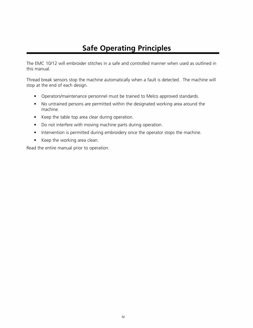
Safe Operating Principles
The EMC 10/12 will embroider stitches in a safe and controlled manner when used as outlined inthis manual.
Thread break sensors stop the machine automatically when a fault is detected. The machine willstop at the end of each design.
• Operators/maintenance personnel must be trained to Melco approved standards.
• No untrained persons are permitted within the designated working area around themachine.
• Keep the table top area clear during operation.
• Do not interfere with moving machine parts during operation.
• Intervention is permitted during embroidery once the operator stops the machine.
• Keep the working area clean.
Read the entire manual prior to operation.
iv
v
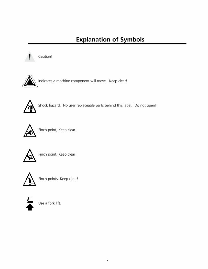
Explanation of Symbols
Caution!
Indicates a machine component will move. Keep clear!
Shock hazard. No user replaceable parts behind this label. Do not open!
Pinch point, Keep clear!
Pinch point, Keep clear!
Pinch points, Keep clear!
Use a fork lift.

vi
This page intentionally left blank

Installation 1-1
1. Installation
Machine Working Environment
The EMC 10/12 peripheral must be positioned on a hard dry flat surface capable of supporting amachine weight of 3,960 lbs (1,800kg). A working corridor of 1.5m must be provided around themachine’s perimeter for operation and maintenance. The area surrounding the machine shouldhave adequate lighting, and the ambient room temperature should not fall below 55 degrees F(13 degrees C).
Moving the Crated Machine
Do not attempt to manually lift or move the EMC 10/12. Use a fork lift to move thecrated machine. Place the lifting forks as diagrammed on the crate.
Removing the Crate
The crate is constructed as illustrated in Figure 1-1. Disassemble according to steps in Figure 1-1.When fully dismantled, the crate, packing material, and wrapper should be disposed of safelyLEAVE THE MACHINE ON THE PALLET.
110268-01 Rev. C 1. Installation
Figure 1-1
1. Remove lid (nailed).2. Remove both ends (nailed).3. Remove top bearers (6x).4. Remove sides (2x).5. Remove hermetically sealed bag.6. Remove hold down nuts (4x).
PALLET
1-2 Installation
EMC 10/12 Installation, Operation, and Maintenance Manual Melco Embroidery Systems
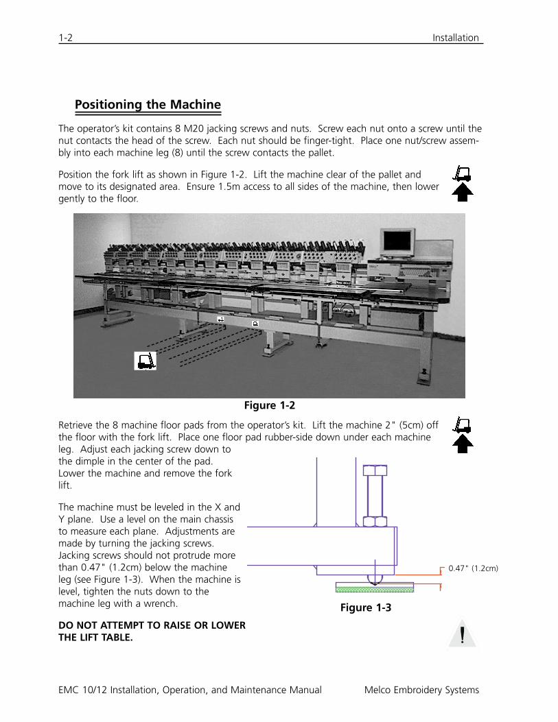
Positioning the Machine
The operator’s kit contains 8 M20 jacking screws and nuts. Screw each nut onto a screw until thenut contacts the head of the screw. Each nut should be finger-tight. Place one nut/screw assem-bly into each machine leg (8) until the screw contacts the pallet.
Position the fork lift as shown in Figure 1-2. Lift the machine clear of the pallet andmove to its designated area. Ensure 1.5m access to all sides of the machine, then lowergently to the floor.
Retrieve the 8 machine floor pads from the operator’s kit. Lift the machine 2" (5cm) offthe floor with the fork lift. Place one floor pad rubber-side down under each machineleg. Adjust each jacking screw down tothe dimple in the center of the pad.Lower the machine and remove the forklift.
The machine must be leveled in the X andY plane. Use a level on the main chassisto measure each plane. Adjustments aremade by turning the jacking screws.Jacking screws should not protrude morethan 0.47" (1.2cm) below the machineleg (see Figure 1-3). When the machine islevel, tighten the nuts down to themachine leg with a wrench.
DO NOT ATTEMPT TO RAISE OR LOWERTHE LIFT TABLE.
Figure 1-2
Figure 1-3
0.47" (1.2cm)

Installation 1-3
Removing the Shipping Clamp
Remove the shipping clamp affixed to the color change housing (see Figure 1-4) by unscrewingthe 4 cap head screws. Attached to the clamp is a pack with 2 button-head screws; affix thesescrews to the color change housing. Retain the clamp and screws; always use the clamp whenthe machine is transported.
Connecting the Monitor and Keyboard
The following step must be performed by a qualified electrical engineer. DO NOT connect themain power supply now. Always use anti-static wristbands when working with printed circuitboards.
The monitor ships in a separate carton. The power leads for the monitor and keyboard are con-nected to the machine. The video lead is connected to the monitor. The keyboard is securelytaped to its base at the right-hand side of the machine. Refer to Figure 1-5 and follow thesesteps to connect the monitor and keyboard.
110268-01 Rev. C 1. Installation
Figure 1-4
1-4 Installation
EMC 10/12 Installation, Operation, and Maintenance Manual Melco Embroidery Systems
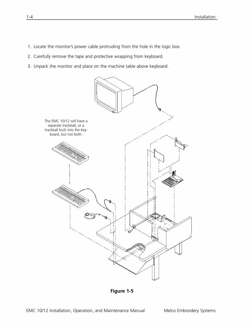
1. Locate the monitor’s power cable protruding from the hole in the logic box.
2. Carefully remove the tape and protective wrapping from keyboard.
3. Unpack the monitor and place on the machine table above keyboard.
Figure 1-5
The EMC 10/12 will have aseparate trackball, or a
trackball built into the key-board, but not both.
Installation 1-5
4. Remove the logic box top casing.
5. Connect the monitor power cable to the monitor.
6. Pass the video cable from the monitor through the hole in the logic box casing and connect tothe video card. Secure with the terminal screws.
7. Replace the logic box casing top.
Connecting Power Cables
1. Assure the power switch is in the OFF position.
2. Connect the power cord to the power socket.
110268-01 Rev. C 1. Installation

1-6 Installation
EMC 10/12 Installation, Operation, and Maintenance Manual Melco Embroidery Systems
This page intentionally left blank
Operation 2-1
2. Operation
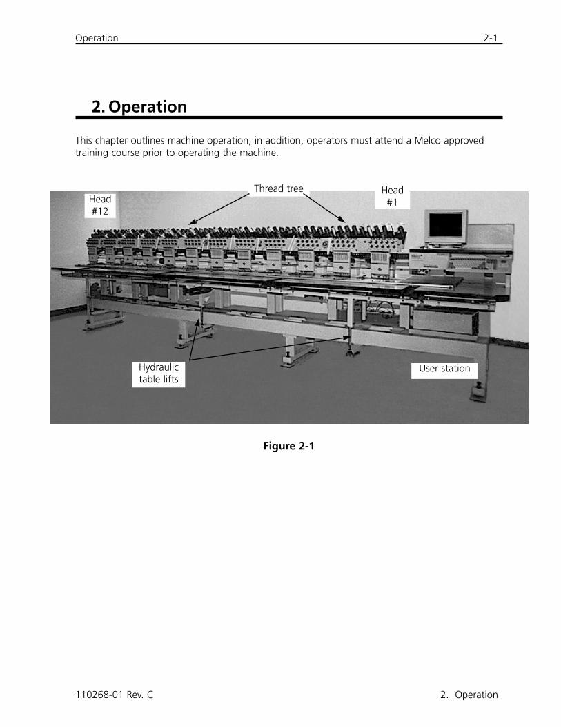
This chapter outlines machine operation; in addition, operators must attend a Melco approvedtraining course prior to operating the machine.
110268-01 Rev. C 2. Operation
Figure 2-1
Thread tree
User station
Head#1Head
#12
Hydraulictable lifts
2-2 Hazards of Operation
EMC 10/12 Installation, Operation, and Maintenance Manual Melco Embroidery Systems
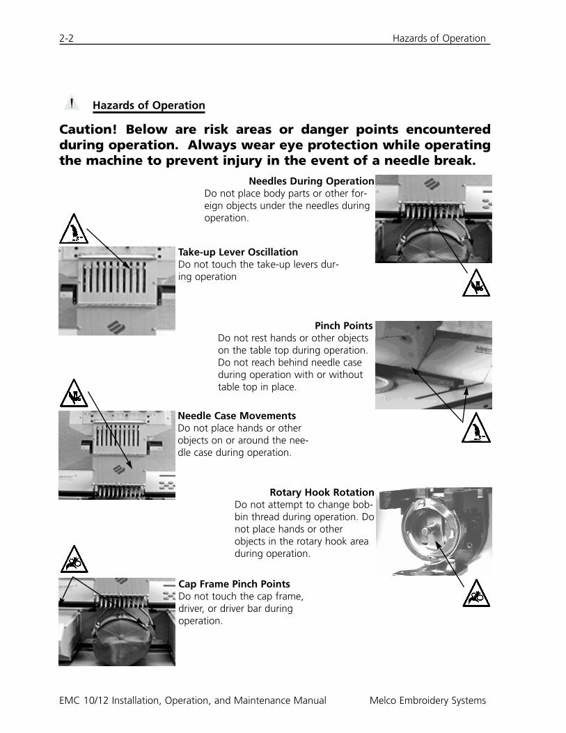
Hazards of Operation
Caution! Below are risk areas or danger points encounteredduring operation. Always wear eye protection while operatingthe machine to prevent injury in the event of a needle break.
Needles During OperationDo not place body parts or other for-eign objects under the needles duringoperation.
Pinch PointsDo not rest hands or other objectson the table top during operation.Do not reach behind needle caseduring operation with or withouttable top in place.
Rotary Hook RotationDo not attempt to change bob-bin thread during operation. Donot place hands or otherobjects in the rotary hook areaduring operation.
Take-up Lever OscillationDo not touch the take-up levers dur-ing operation
Needle Case MovementsDo not place hands or otherobjects on or around the nee-dle case during operation.
Cap Frame Pinch PointsDo not touch the cap frame,driver, or driver bar duringoperation.
Threading 2-3
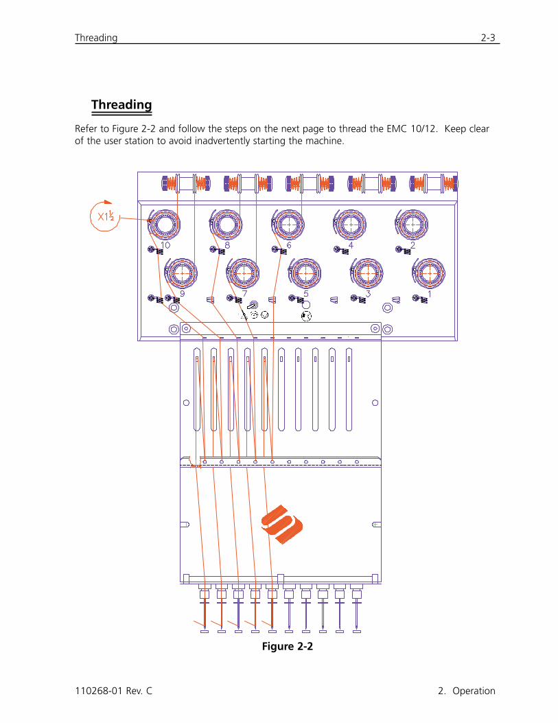
Threading
Refer to Figure 2-2 and follow the steps on the next page to thread the EMC 10/12. Keep clearof the user station to avoid inadvertently starting the machine.
110268-01 Rev. C 2. Operation
Figure 2-2
2-4 Threading
EMC 10/12 Installation, Operation, and Maintenance Manual Melco Embroidery Systems
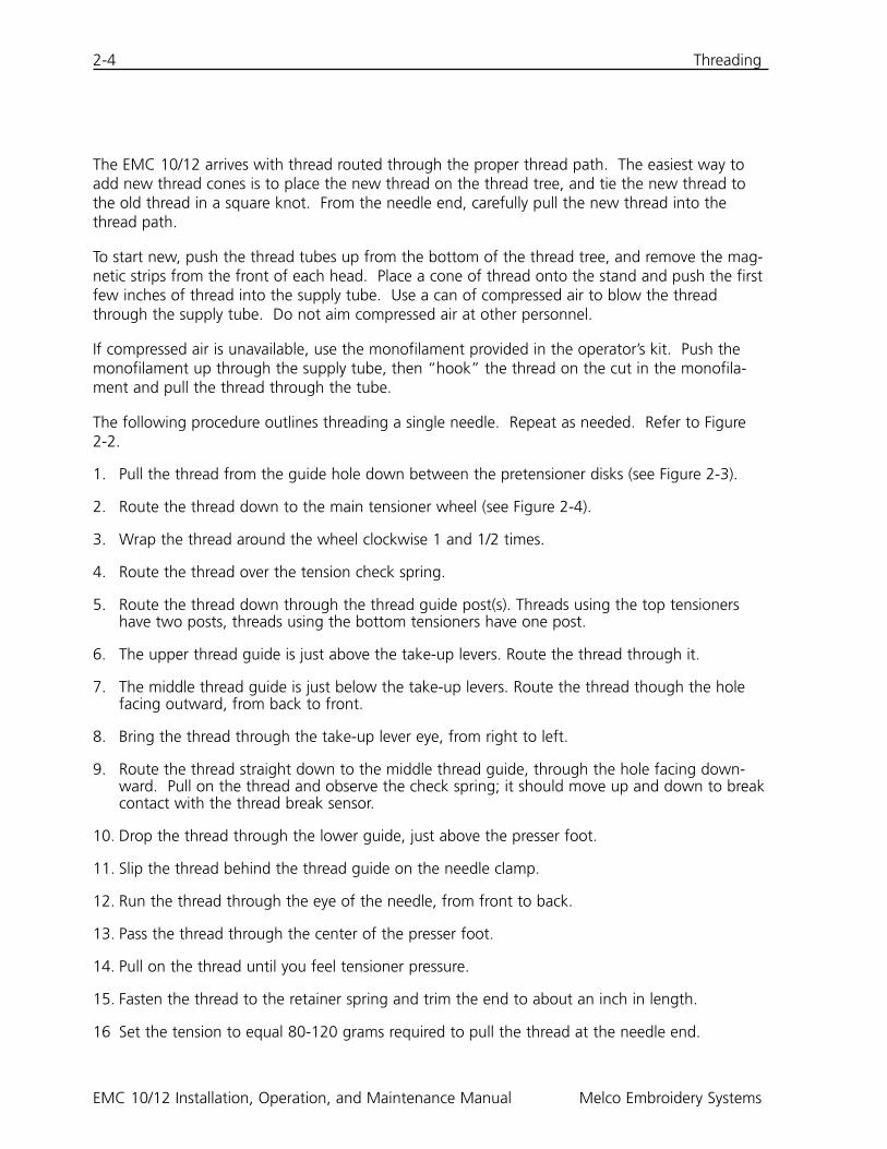
The EMC 10/12 arrives with thread routed through the proper thread path. The easiest way toadd new thread cones is to place the new thread on the thread tree, and tie the new thread tothe old thread in a square knot. From the needle end, carefully pull the new thread into thethread path.
To start new, push the thread tubes up from the bottom of the thread tree, and remove the mag-netic strips from the front of each head. Place a cone of thread onto the stand and push the firstfew inches of thread into the supply tube. Use a can of compressed air to blow the threadthrough the supply tube. Do not aim compressed air at other personnel.
If compressed air is unavailable, use the monofilament provided in the operator’s kit. Push themonofilament up through the supply tube, then “hook” the thread on the cut in the monofila-ment and pull the thread through the tube.
The following procedure outlines threading a single needle. Repeat as needed. Refer to Figure 2-2.
1. Pull the thread from the guide hole down between the pretensioner disks (see Figure 2-3).
2. Route the thread down to the main tensioner wheel (see Figure 2-4).
3. Wrap the thread around the wheel clockwise 1 and 1/2 times.
4. Route the thread over the tension check spring.
5. Route the thread down through the thread guide post(s). Threads using the top tensionershave two posts, threads using the bottom tensioners have one post.
6. The upper thread guide is just above the take-up levers. Route the thread through it.
7. The middle thread guide is just below the take-up levers. Route the thread though the holefacing outward, from back to front.
8. Bring the thread through the take-up lever eye, from right to left.
9. Route the thread straight down to the middle thread guide, through the hole facing down-ward. Pull on the thread and observe the check spring; it should move up and down to breakcontact with the thread break sensor.
10. Drop the thread through the lower guide, just above the presser foot.
11. Slip the thread behind the thread guide on the needle clamp.
12. Run the thread through the eye of the needle, from front to back.
13. Pass the thread through the center of the presser foot.
14. Pull on the thread until you feel tensioner pressure.
15. Fasten the thread to the retainer spring and trim the end to about an inch in length.
16 Set the tension to equal 80-120 grams required to pull the thread at the needle end.
Tensions 2-5
Tensions
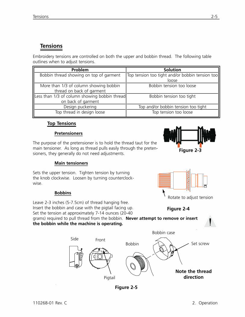
Embroidery tensions are controlled on both the upper and bobbin thread. The following tableoutlines when to adjust tensions.
Top Tensions
Pretensioners
The purpose of the pretensioner is to hold the thread taut for themain tensioner. As long as thread pulls easily through the preten-sioners, they generally do not need adjustments.
Main tensioners
Sets the upper tension. Tighten tension by turningthe knob clockwise. Loosen by turning counterclock-wise.
Bobbins
Leave 2-3 inches (5-7.5cm) of thread hanging free.Insert the bobbin and case with the pigtail facing up.Set the tension at approximately 7-14 ounces (20-40grams) required to pull thread from the bobbin. Never attempt to remove or insertthe bobbin while the machine is operating.
110268-01 Rev. C 2. Operation
ProblemBobbin thread showing on top of garment
More than 1/3 of column showing bobbinthread on back of garment
Less than 1/3 of column showing bobbin threadon back of garmentDesign puckering
Top thread in design loose
SolutionTop tension too tight and/or bobbin tension too
looseBobbin tension too loose
Bobbin tension too tight
Top and/or bobbin tension too tightTop tension too loose
Figure 2-4
Rotate to adjust tension
Figure 2-3
Figure 2-5
Side FrontBobbin
Bobbin case
Pigtail
Set screw
Note the threaddirection
2-6 Keypad
EMC 10/12 Installation, Operation, and Maintenance Manual Melco Embroidery Systems
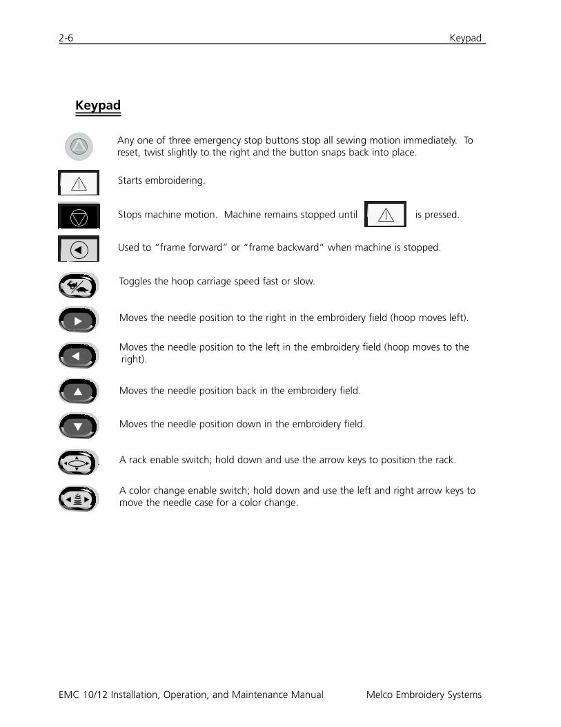
Keypad
▲
Starts embroidering.
Stops machine motion. Machine remains stopped until is pressed.
Used to “frame forward” or “frame backward” when machine is stopped.
Toggles the hoop carriage speed fast or slow.
▼ Moves the needle position to the right in the embroidery field (hoop moves left).
▲
Moves the needle position to the left in the embroidery field (hoop moves to theright).
▲ Moves the needle position back in the embroidery field.
▼ Moves the needle position down in the embroidery field.
▲
▼
▼▲ ▲
A rack enable switch; hold down and use the arrow keys to position the rack.
Any one of three emergency stop buttons stop all sewing motion immediately. Toreset, twist slightly to the right and the button snaps back into place.
▼▲
A color change enable switch; hold down and use the left and right arrow keys tomove the needle case for a color change.
Control Panel 2-7
Control Panel
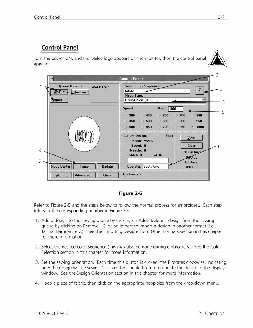
Turn the power ON, and the Melco logo appears on the monitor, then the control panelappears.
Refer to Figure 2-5 and the steps below to follow the normal process for embroidery. Each steprefers to the corresponding number in Figure 2-6.
1. Add a design to the sewing queue by clicking on Add. Delete a design from the sewingqueue by clicking on Remove. Click on Import to import a design in another format (i.e.,Tajima, Barudan, etc.). See the Importing Designs from Other Formats section in this chapterfor more information.
2. Select the desired color sequence (this may also be done during embroidery). See the ColorSelection section in this chapter for more information.
3. Set the sewing orientation. Each time this button is clicked, the F rotates clockwise, indicatinghow the design will be sewn. Click on the Update button to update the design in the displaywindow. See the Design Orientation section in this chapter for more information.
4. Hoop a piece of fabric, then click on the appropriate hoop size from the drop-down menu.
110268-01 Rev. C 2. Operation
Figure 2-6
1
2
3
4
5
6
7
8
2-8 Control Panel
EMC 10/12 Installation, Operation, and Maintenance Manual Melco Embroidery Systems
5. Change the sewing speed if desired. Speed defaults to the last value entered until changedagain. Choose a preset speed or type the value into the box in increments of 10. Sewingspeed may be changed at any time (even while embroidering). Maximum speed is 1000stitches per minute (spm).
6. Enter the operator’s name to store statistical information such as stitches sewn and threadbreaks.
7. Click on the Hoop Center button to move the rack to the center of the selectedhoop.
8. Click on Trace to trace the design before sewing to make sure it will fit in the select-ed hoop.
Ensure the table top and all sewing heads are unobstructed then press . Themachine beeps several times to alert all personnel to stay clear and begins embroider-ing.
Loading A Design
You may retrieve a design from any directory or subdirectory within either the C: drive (hard disk)or the A: drive (external floppy disk).
Previewing A Design
There are two ways to preview a design; one is by looking at the outline only, the other is byusing EDS III software. Both methods are explained below:
To look at the outline of a design:
1. Go to the Control Panel to add designs to the sewing queue.
2. Scroll through the design list and click on a design to highlight it.
3. Click on Update.
The outline of the design will be shown in the Display Window.
To look at the complete design:
1. From the Control Panel, click on Close.
2. Go to File and click on Open.
3. Scroll through the design list and double-click on a design.
The complete design will be shown on the screen.
Viewing the Design While it Sews 2-9
Viewing the Design While it Sews
As a design sews, you can watch it being created on the screen by following these instructions:
1. Click on the View button in the Control Panel and the design is displayed stitch by stitch.
2. Return to the Control Panel by pressing any key.
Viewing the Design Without Sewing
To see the design or part of the design without sewing:
1. Click on Advanced... and a dialog box will appear.
2. In the bottom-left corner is a button labeled Move Now. Below that are two boxes for X/Ycoordinates (explained in detail later in this Chapter) and below those is a grayed-out box forStitch Number.
3. Click on the Stitch Number box and the label will change to solid black lettering. The X/Ycoordinate boxes will become grayed-out.
4. Type in a stitch number. If you want to see the entire design, type in the last stitchnumber. For example, if a design has 9137 stitches, type in 9137. The rack willmove to that stitch.
5. Press [ENTER] or click on Exit.
6. Click on View in the Control Panel. The design displays up to the stitch number you entered.
7. Press any key to return to the Control Panel.
8. Reset the stitch count before sewing by clicking on Clear.
Importing Designs From Other Formats
You have the option of importing designs that are not in the DOS format. When you import otherdesigns, their format is automatically translated.
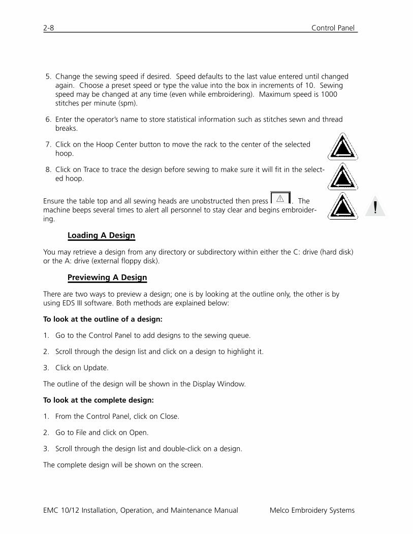
From the Control Panel, click on Import (refer toFigure 2-6). A dialog box appears (shown in Figure2-6). giving you the option to change drives andchoose from a variety of common formats.
Once you find the design you want click on thefilename and then click on OK, or double-click onthe filename and the design will be loaded into theDesign Queue.
110268-01 Rev. C 2. Operation
Figure 2-7
2-10 Setting the Hoop Size
EMC 10/12 Installation, Operation, and Maintenance Manual Melco Embroidery Systems
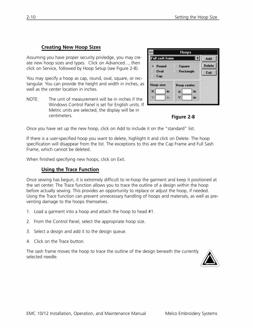
Creating New Hoop Sizes
Assuming you have proper security privledge, you may cre-ate new hoop sizes and types. Click on Advanced..., thenclick on Service, followed by Hoop Setup (see Figure 2-8).
You may specify a hoop as cap, round, oval, square, or rec-tangular. You can provide the height and width in inches, aswell as the center location in inches.
NOTE: The unit of measurement will be in inches if theWindows Control Panel is set for English units. IfMetric units are selected, the display will be incentimeters.
Once you have set up the new hoop, click on Add to include it on the "standard" list.
If there is a user-specified hoop you want to delete, highlight it and click on Delete. The hoopspecification will disappear from the list. The exceptions to this are the Cap Frame and Full SashFrame, which cannot be deleted.
When finished specifying new hoops, click on Exit.
Using the Trace Function
Once sewing has begun, it is extremely difficult to re-hoop the garment and keep it positioned atthe set center. The Trace function allows you to trace the outline of a design within the hoopbefore actually sewing. This provides an opportunity to replace or adjust the hoop, if needed.Using the Trace function can prevent unnecessary handling of hoops and materials, as well as pre-venting damage to the hoops themselves.
1. Load a garment into a hoop and attach the hoop to head #1.
2. From the Control Panel, select the appropriate hoop size.
3. Select a design and add it to the design queue.
4. Click on the Trace button.
The sash frame moves the hoop to trace the outline of the design beneath the currentlyselected needle.
Figure 2-8
Changing the Design Orientation 2-11
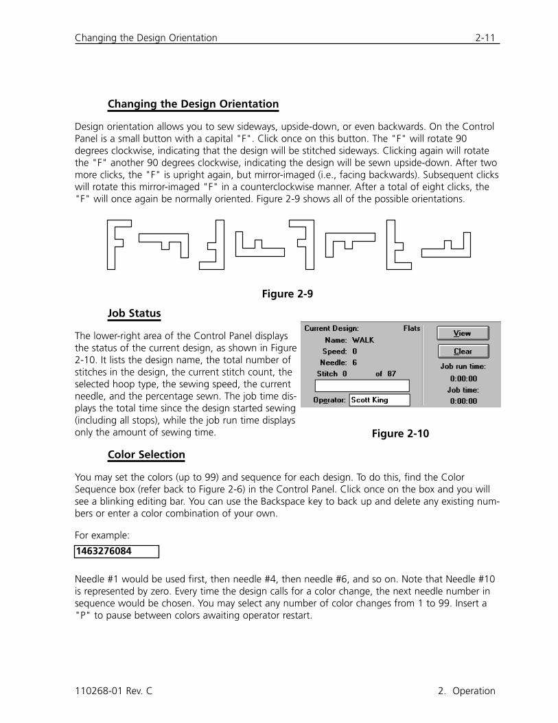
Changing the Design Orientation
Design orientation allows you to sew sideways, upside-down, or even backwards. On the ControlPanel is a small button with a capital "F". Click once on this button. The "F" will rotate 90degrees clockwise, indicating that the design will be stitched sideways. Clicking again will rotatethe "F" another 90 degrees clockwise, indicating the design will be sewn upside-down. After twomore clicks, the "F" is upright again, but mirror-imaged (i.e., facing backwards). Subsequent clickswill rotate this mirror-imaged "F" in a counterclockwise manner. After a total of eight clicks, the"F" will once again be normally oriented. Figure 2-9 shows all of the possible orientations.
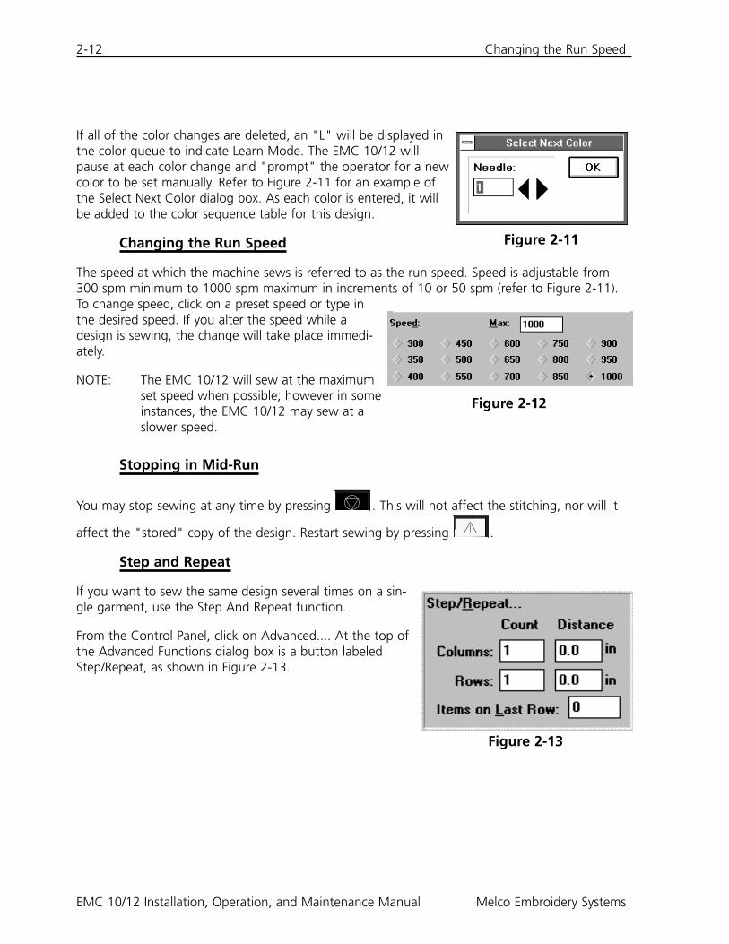
Job Status
The lower-right area of the Control Panel displaysthe status of the current design, as shown in Figure2-10. It lists the design name, the total number ofstitches in the design, the current stitch count, theselected hoop type, the sewing speed, the currentneedle, and the percentage sewn. The job time dis-plays the total time since the design started sewing(including all stops), while the job run time displaysonly the amount of sewing time.
Color Selection
You may set the colors (up to 99) and sequence for each design. To do this, find the ColorSequence box (refer back to Figure 2-6) in the Control Panel. Click once on the box and you willsee a blinking editing bar. You can use the Backspace key to back up and delete any existing num-bers or enter a color combination of your own.
For example:
Needle #1 would be used first, then needle #4, then needle #6, and so on. Note that Needle #10is represented by zero. Every time the design calls for a color change, the next needle number insequence would be chosen. You may select any number of color changes from 1 to 99. Insert a"P" to pause between colors awaiting operator restart.
110268-01 Rev. C 2. Operation
Figure 2-9
Figure 2-10
1463276084
2-12 Changing the Run Speed
EMC 10/12 Installation, Operation, and Maintenance Manual Melco Embroidery Systems
If all of the color changes are deleted, an "L" will be displayed inthe color queue to indicate Learn Mode. The EMC 10/12 willpause at each color change and "prompt" the operator for a newcolor to be set manually. Refer to Figure 2-11 for an example ofthe Select Next Color dialog box. As each color is entered, it willbe added to the color sequence table for this design.
Changing the Run Speed
The speed at which the machine sews is referred to as the run speed. Speed is adjustable from300 spm minimum to 1000 spm maximum in increments of 10 or 50 spm (refer to Figure 2-11).To change speed, click on a preset speed or type inthe desired speed. If you alter the speed while adesign is sewing, the change will take place immedi-ately.
NOTE: The EMC 10/12 will sew at the maximumset speed when possible; however in someinstances, the EMC 10/12 may sew at aslower speed.
Stopping in Mid-Run
You may stop sewing at any time by pressing . This will not affect the stitching, nor will it
affect the "stored" copy of the design. Restart sewing by pressing .
Step and Repeat
If you want to sew the same design several times on a sin-gle garment, use the Step And Repeat function.
From the Control Panel, click on Advanced.... At the top ofthe Advanced Functions dialog box is a button labeledStep/Repeat, as shown in Figure 2-13.
Figure 2-11
Figure 2-12
Figure 2-13
Step and Repeat 2-13
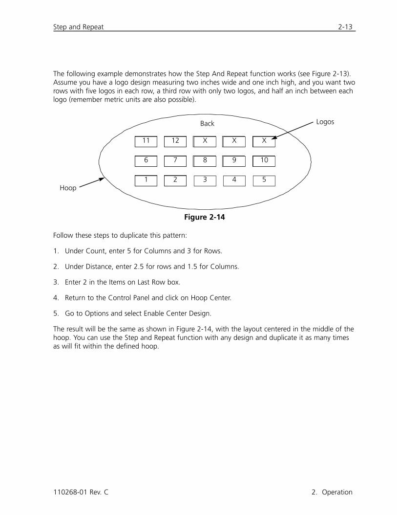
The following example demonstrates how the Step And Repeat function works (see Figure 2-13).Assume you have a logo design measuring two inches wide and one inch high, and you want tworows with five logos in each row, a third row with only two logos, and half an inch between eachlogo (remember metric units are also possible).
Follow these steps to duplicate this pattern:
1. Under Count, enter 5 for Columns and 3 for Rows.
2. Under Distance, enter 2.5 for rows and 1.5 for Columns.
3. Enter 2 in the Items on Last Row box.
4. Return to the Control Panel and click on Hoop Center.
5. Go to Options and select Enable Center Design.
The result will be the same as shown in Figure 2-14, with the layout centered in the middle of thehoop. You can use the Step and Repeat function with any design and duplicate it as many timesas will fit within the defined hoop.
110268-01 Rev. C 2. Operation
Figure 2-14
Hoop
LogosBack
3 4 51 2
6 7 8 9 10
11 12 X X X
2-14 Security
EMC 10/12 Installation, Operation, and Maintenance Manual Melco Embroidery Systems
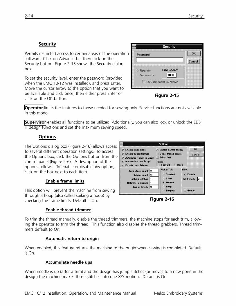
Security
Permits restricted access to certain areas of the operationsoftware. Click on Advanced..., then click on theSecurity button. Figure 2-15 shows the Security dialogbox.
To set the security level, enter the password (providedwhen the EMC 10/12 was installed), and press Enter.Move the cursor arrow to the option that you want tobe available and click once, then either press Enter orclick on the OK button.
Operator limits the features to those needed for sewing only. Service functions are not availablein this mode.
Supervisor enables all functions to be utilized. Additionally, you can also lock or unlock the EDSIII design functions and set the maximum sewing speed.
Options
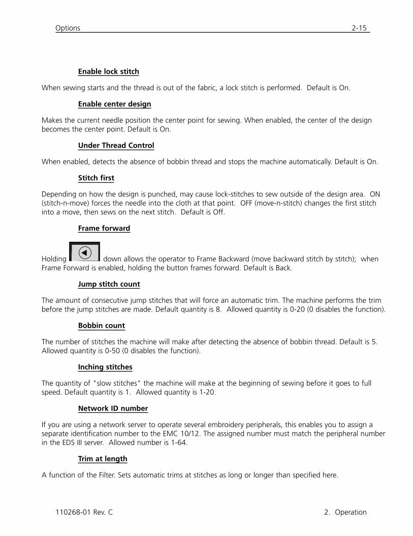
The Options dialog box (Figure 2-16) allows accessto several different operation settings. To accessthe Options box, click the Options button from thecontrol panel (Figure 2-6). A description of theoptions follows. To enable or disable any option,click on the box next to each item.
Enable frame limits
This option will prevent the machine from sewingthrough a hoop (also called spiking a hoop) bychecking the frame limits. Default is On.
Enable thread trimmer
To trim the thread manually, disable the thread trimmers; the machine stops for each trim, allow-ing the operator to trim the thread. This function also disables the thread grabbers. Thread trim-mers default to On.
Automatic return to origin
When enabled, this feature returns the machine to the origin when sewing is completed. Defaultis On.
Accumulate needle ups
When needle is up (after a trim) and the design has jump stitches (or moves to a new point in thedesign) the machine makes those stitches into one X/Y motion. Default is On.
Figure 2-15
Figure 2-16
Options 2-15
Enable lock stitch
When sewing starts and the thread is out of the fabric, a lock stitch is performed. Default is On.
Enable center design
Makes the current needle position the center point for sewing. When enabled, the center of the designbecomes the center point. Default is On.
Under Thread Control
When enabled, detects the absence of bobbin thread and stops the machine automatically. Default is On.
Stitch first
Depending on how the design is punched, may cause lock-stitches to sew outside of the design area. ON(stitch-n-move) forces the needle into the cloth at that point. OFF (move-n-stitch) changes the first stitchinto a move, then sews on the next stitch. Default is Off.
Frame forward
Holding down allows the operator to Frame Backward (move backward stitch by stitch); whenFrame Forward is enabled, holding the button frames forward. Default is Back.
Jump stitch count
The amount of consecutive jump stitches that will force an automatic trim. The machine performs the trimbefore the jump stitches are made. Default quantity is 8. Allowed quantity is 0-20 (0 disables the function).
Bobbin count
The number of stitches the machine will make after detecting the absence of bobbin thread. Default is 5.Allowed quantity is 0-50 (0 disables the function).
Inching stitches
The quantity of "slow stitches" the machine will make at the beginning of sewing before it goes to fullspeed. Default quantity is 1. Allowed quantity is 1-20.
Network ID number
If you are using a network server to operate several embroidery peripherals, this enables you to assign aseparate identification number to the EMC 10/12. The assigned number must match the peripheral numberin the EDS III server. Allowed number is 1-64.
Trim at length
A function of the Filter. Sets automatic trims at stitches as long or longer than specified here.
▲
110268-01 Rev. C 2. Operation
2-16 Options
EMC 10/12 Installation, Operation, and Maintenance Manual Melco Embroidery Systems
Picker tail
Allows you to select the length of thread tail left after a trim.
Filter
Converts jump stitches into a single stitch. Use Trim at Length to insert automatic trims.
SS length
Sets the shortest stitch length allowed when the Filter is enabled.
Gentle
Reduces the maximum stitch length permitted at a given speed. Permits slower rack movements, butyields better embroidery. Analogous to the "gentle cycle" of a washing machine.
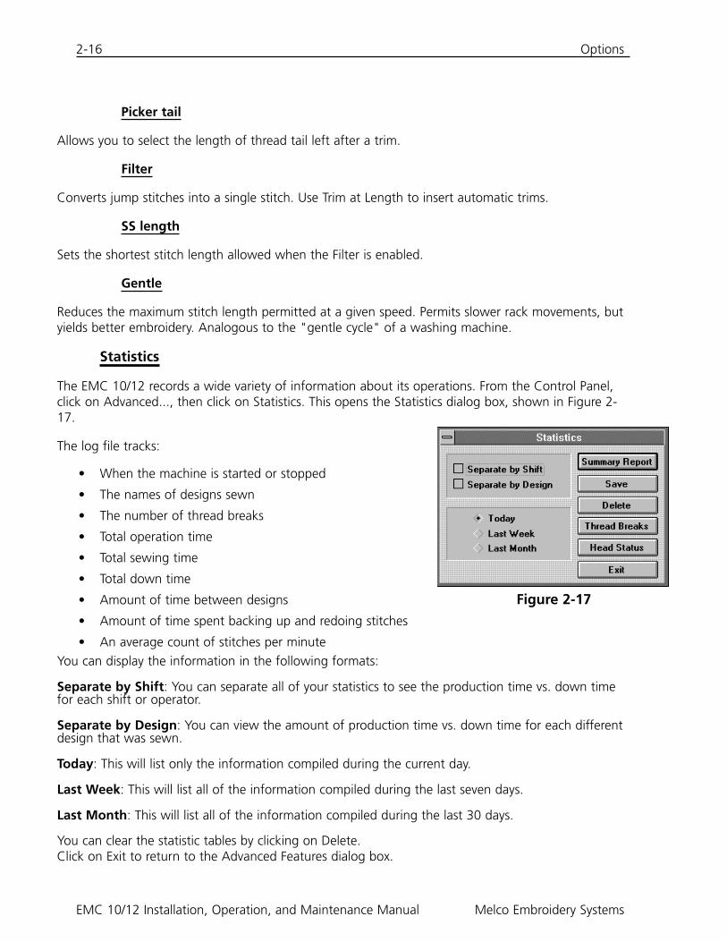
Statistics
The EMC 10/12 records a wide variety of information about its operations. From the Control Panel,click on Advanced..., then click on Statistics. This opens the Statistics dialog box, shown in Figure 2-17.
The log file tracks:
• When the machine is started or stopped
• The names of designs sewn
• The number of thread breaks
• Total operation time
• Total sewing time
• Total down time
• Amount of time between designs
• Amount of time spent backing up and redoing stitches
• An average count of stitches per minuteYou can display the information in the following formats:
Separate by Shift: You can separate all of your statistics to see the production time vs. down timefor each shift or operator.
Separate by Design: You can view the amount of production time vs. down time for each differentdesign that was sewn.
Today: This will list only the information compiled during the current day.
Last Week: This will list all of the information compiled during the last seven days.
Last Month: This will list all of the information compiled during the last 30 days.
You can clear the statistic tables by clicking on Delete.Click on Exit to return to the Advanced Features dialog box.
Figure 2-17
Move Now 2-17
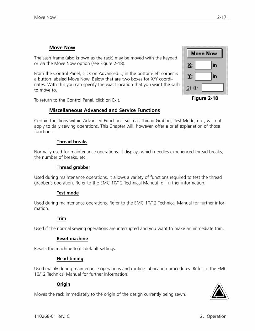
Move Now
The sash frame (also known as the rack) may be moved with the keypador via the Move Now option (see Figure 2-18).
From the Control Panel, click on Advanced...; in the bottom-left corner isa button labeled Move Now. Below that are two boxes for X/Y coordi-nates. With this you can specify the exact location that you want the sashto move to.
To return to the Control Panel, click on Exit.
Miscellaneous Advanced and Service Functions
Certain functions within Advanced Functions, such as Thread Grabber, Test Mode, etc., will notapply to daily sewing operations. This Chapter will, however, offer a brief explanation of thosefunctions.
Thread breaks
Normally used for maintenance operations. It displays which needles experienced thread breaks,the number of breaks, etc.
Thread grabber
Used during maintenance operations. It allows a variety of functions required to test the threadgrabber's operation. Refer to the EMC 10/12 Technical Manual for further information.
Test mode
Used during maintenance operations. Refer to the EMC 10/12 Technical Manual for further infor-mation.
Trim
Used if the normal sewing operations are interrupted and you want to make an immediate trim.
Reset machine
Resets the machine to its default settings.
Head timing
Used mainly during maintenance operations and routine lubrication procedures. Refer to the EMC10/12 Technical Manual for further information.
Origin
Moves the rack immediately to the origin of the design currently being sewn.
110268-01 Rev. C 2. Operation
Figure 2-18

2-18 Miscellaneous Features
EMC 10/12 Installation, Operation, and Maintenance Manual Melco Embroidery Systems
This page intentionally left blank.
Preparing the Material 3-1
3. Hoops and Frames
Preparing the Material
Whether you are sewing flat goods, tubular goods (such as sweatshirts), or caps, you must firstplace your material into an appropriate hoop. The EMC 10/12 has the same hooping versatility asall of the sewing peripherals in the Melco line of embroidery equipment.
Flat Goods Hooping
Whenever you hoop material, make sure that it is straight, fold-free, and stretched tightly. Followthese steps for proper hooping.
1. Use the right size hoop for the job. The design should fit inside the hoop with a small marginof space between it and the hoop, but without a lot of extra material.
NOTE: The Trace function allows you to check if a design will fit in the hoop. Refer to Chapter2 for more information.
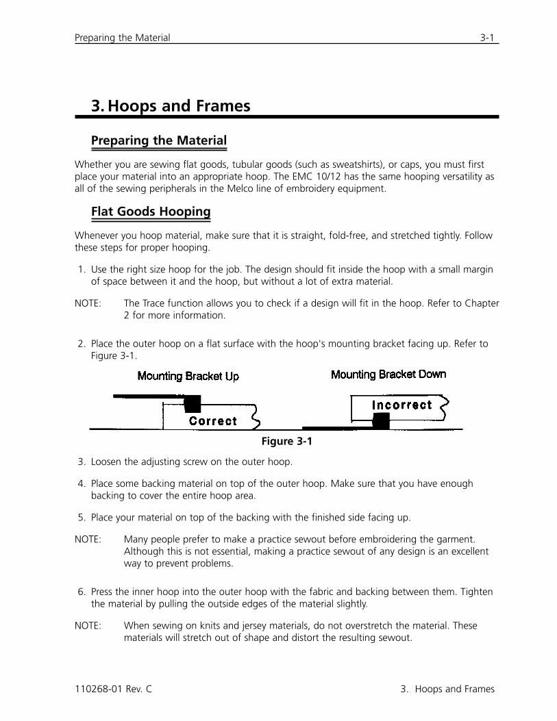
2. Place the outer hoop on a flat surface with the hoop's mounting bracket facing up. Refer toFigure 3-1.
3. Loosen the adjusting screw on the outer hoop.
4. Place some backing material on top of the outer hoop. Make sure that you have enoughbacking to cover the entire hoop area.
5. Place your material on top of the backing with the finished side facing up.
NOTE: Many people prefer to make a practice sewout before embroidering the garment.Although this is not essential, making a practice sewout of any design is an excellentway to prevent problems.
6. Press the inner hoop into the outer hoop with the fabric and backing between them. Tightenthe material by pulling the outside edges of the material slightly.
NOTE: When sewing on knits and jersey materials, do not overstretch the material. Thesematerials will stretch out of shape and distort the resulting sewout.
110268-01 Rev. C 3. Hoops and Frames
Figure 3-1
3-2 The Sash Frame
EMC 10/12 Installation, Operation, and Maintenance Manual Melco Embroidery Systems
7. Tighten the adjusting screw on the outer hoop. Tightening this screw will not tighten the fab-ric, it simply secures it. Tightening the screw too much can "burn" a permanent circle in yourmaterial.
The Sash Frame
The sash frame consists of aluminum beams attached to the drive motors. Most garment hoopswill attach to this sash assembly, but for oversize materials and cap frames, a different sasharrangement must be used (which is explained in more detail later in this section).
Attaching Hoops To The Sash Frame
To attach hoops to the sash frame, simply lay the hoop with the brackets on the frame, align themounting holes with the holes in the brackets, and install the thumb screws snugly. Neverattempt to attach hoops to the sash frame while the machine is operating.
Do not use pliers or other tools to tighten these screws, or damage may result. Use a coin toloosen the screws if they are too tight to loosen by hand.
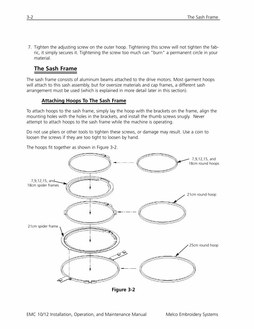
The hoops fit together as shown in Figure 3-2.
Figure 3-2
7,9,12,15, and18cm spider frames
7,9,12,15, and18cm round hoops
21cm round hoop
21cm spider frame
25cm round hoop

The Sash Frame 3-3
Disconnecting the Sash Frame
In order to attach cap frames, sew tubular goods, or perform certain types of service adjustments,you must disconnect the sash frame before lowering the sewing table. Only qualified operators ormaintenance personnel should perform this task.
1. Remove all hoops.
2. Using the keypad, press the [DOWN ARROW] key until the lower edge of the sashframe is at the forward part of the sewing table and far enough to the right toexpose the #1 Y-drive on the drop table.
3. Referring to Figure 3-3, remove the six socket head capscrews labeled "A" from the sash frame (located belowthe User Station). Do not loosen or remove any otherscrews or nuts.
4. Referring to Figure 3-4, remove the two socket head capscrews labeled "B" from the Y-axis bearing supports. Donot loosen or remove any other screws in this area.Repeat this step at all four Y-axis bearing support loca-tions.
5. Referring to Figure 3-5, remove the two socket head capscrews designated as "C" at the far end of the sashframe (located below sewing head #12). Do not loosenor remove any other screws in this area.
6. Slide the loose part of the sash frame to the left and tothe front until it sits only on the front and left end of thedrop table. Do not remove the sash from the table. Thetable may be lowered with the sash frame still on thetable top without interfering with cap or tubular frames.
110268-01 Rev. C 3. Hoops and Frames
Figure 3-3
A
Figure 3-4
B
Figure 3-5
C
3-4 Oversize Flat Goods
EMC 10/12 Installation, Operation, and Maintenance Manual Melco Embroidery Systems
Lowering the Table
A crank-type handle is underneath the table, located at about the mid-point. Unfold thehandle and rotate in a counter-clockwise direction to lower the table. If the table doesnot move freely, check for an obstruction. Keep rotating until the table stops at the fulldown position, then fold the handle back underneath.
Oversize Flat Goods
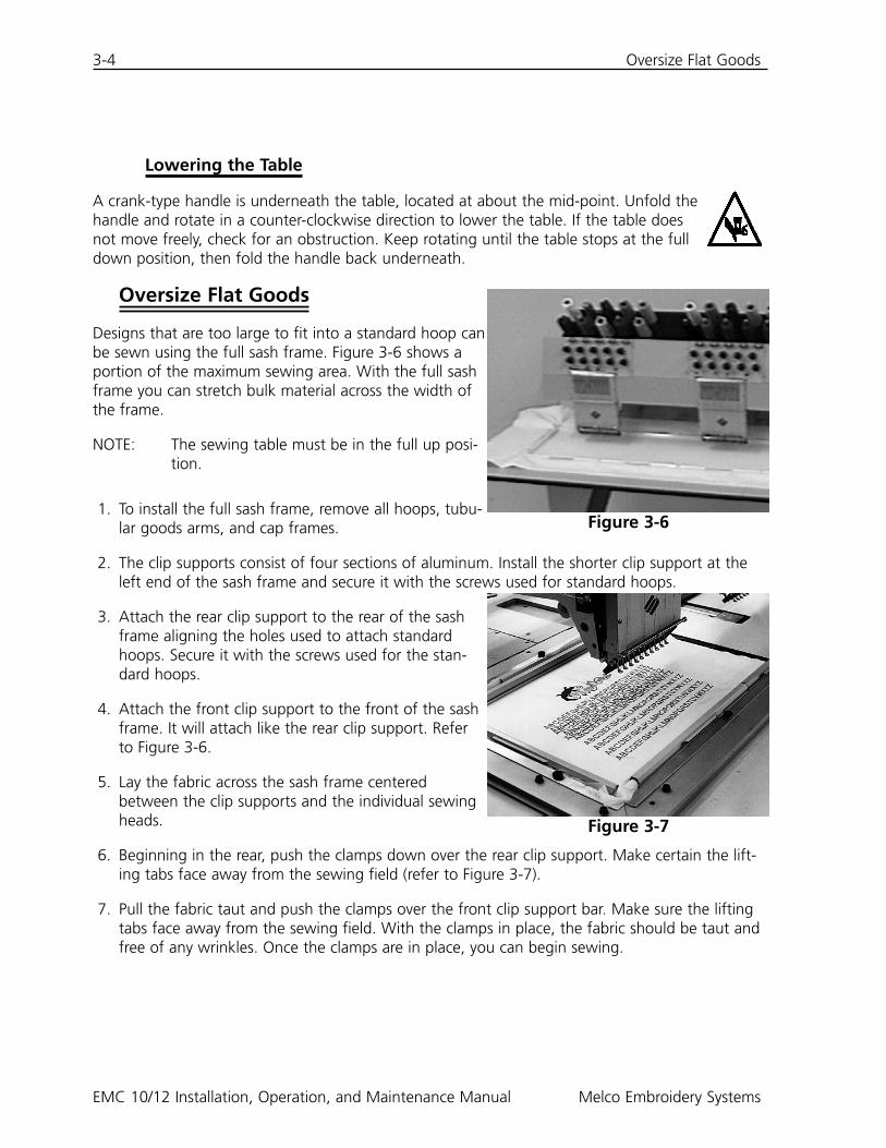
Designs that are too large to fit into a standard hoop canbe sewn using the full sash frame. Figure 3-6 shows aportion of the maximum sewing area. With the full sashframe you can stretch bulk material across the width ofthe frame.
NOTE: The sewing table must be in the full up posi-tion.
1. To install the full sash frame, remove all hoops, tubu-lar goods arms, and cap frames.
2. The clip supports consist of four sections of aluminum. Install the shorter clip support at theleft end of the sash frame and secure it with the screws used for standard hoops.
3. Attach the rear clip support to the rear of the sashframe aligning the holes used to attach standardhoops. Secure it with the screws used for the stan-dard hoops.
4. Attach the front clip support to the front of the sashframe. It will attach like the rear clip support. Referto Figure 3-6.
5. Lay the fabric across the sash frame centeredbetween the clip supports and the individual sewingheads.
6. Beginning in the rear, push the clamps down over the rear clip support. Make certain the lift-ing tabs face away from the sewing field (refer to Figure 3-7).
7. Pull the fabric taut and push the clamps over the front clip support bar. Make sure the liftingtabs face away from the sewing field. With the clamps in place, the fabric should be taut andfree of any wrinkles. Once the clamps are in place, you can begin sewing.
Figure 3-6
Figure 3-7
Tubular Goods 3-5
Tubular Goods
For tubular garments (pillow cases, jacket sleeves, etc.),use the tubular frame.
NOTE: Remove the sash frame and lower thesewing table below the cylinder arm.
1. Using the keypad, center the sash framebetween the sewing heads.
2. Disconnect the front portion of the sash frame andlower the sewing table (refer to the previous sec-tion).
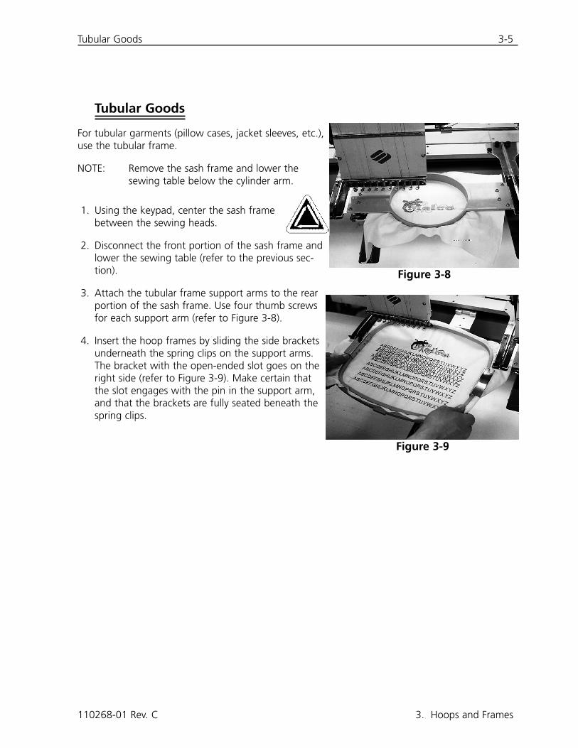
3. Attach the tubular frame support arms to the rearportion of the sash frame. Use four thumb screwsfor each support arm (refer to Figure 3-8).
4. Insert the hoop frames by sliding the side bracketsunderneath the spring clips on the support arms.The bracket with the open-ended slot goes on theright side (refer to Figure 3-9). Make certain thatthe slot engages with the pin in the support arm,and that the brackets are fully seated beneath thespring clips.
110268-01 Rev. C 3. Hoops and Frames
Figure 3-8
Figure 3-9
3-6 Caps and Visors
EMC 10/12 Installation, Operation, and Maintenance Manual Melco Embroidery Systems
Caps and Visors
Follow these steps to properly hoop a cap or visor.
NOTE: The sewing table must be completely down.
1. Insert the cap frame into the cap gauge.
2. Open the cap frame cover with the latch on the frame's left side and lift so that it rests on thestop on the right side of the gauge.
NOTE: If you use backing, place it in the cap before loading the cap into the frame.
3. Slide the top of the cap around frame. Keep the sides of the cap inside the frame's outeredges. Push the cap onto the frame as far as possible. On most caps, you will need to turn thesweat band inside-out. If there is a braided rope trim across the bill, pull it to the back of thecap and out of the sewing area.
4. Snap the bill holders (the bungy cords) over the bill. Pull the cap front tight on the frame.
5. Close the frame's cover. Keep the cap as straight, fold-free, and tight as possible.
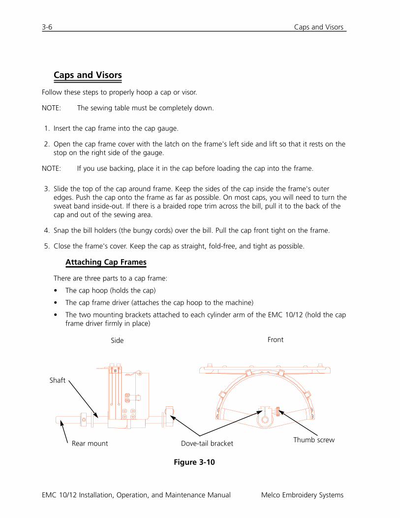
Attaching Cap Frames
There are three parts to a cap frame:
• The cap hoop (holds the cap)
• The cap frame driver (attaches the cap hoop to the machine)
• The two mounting brackets attached to each cylinder arm of the EMC 10/12 (hold the capframe driver firmly in place)
Figure 3-10
Side Front
Rear mount Dove-tail bracket Thumb screw
Shaft
Caps and Visors 3-7
1. Center the sash frame assembly in both X and Y directions using the arrow keys onthe keypad.
2. Disconnect the standard sash frame (refer to the Flat Garments section) and lower the sewingtable to its lowest position to gain access to the cap frame mounting brackets.
3. Under the #1 cylinder arm, locate two mounting brackets:
• A dove-tail bracket under the needle area.
• A bracket with a round hole at the rear of the cylinder arm.
4. Loosen the thumb screw on the rear bracket.
5. Loosen the thumb screw on the dove-tail bracket.
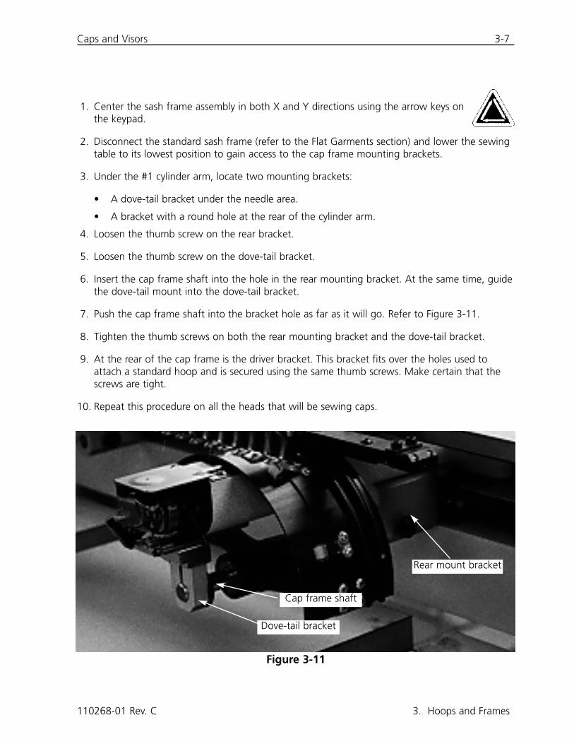
6. Insert the cap frame shaft into the hole in the rear mounting bracket. At the same time, guidethe dove-tail mount into the dove-tail bracket.
7. Push the cap frame shaft into the bracket hole as far as it will go. Refer to Figure 3-11.
8. Tighten the thumb screws on both the rear mounting bracket and the dove-tail bracket.
9. At the rear of the cap frame is the driver bracket. This bracket fits over the holes used toattach a standard hoop and is secured using the same thumb screws. Make certain that thescrews are tight.
10. Repeat this procedure on all the heads that will be sewing caps.
110268-01 Rev. C 3. Hoops and Frames
Figure 3-11
Dove-tail bracket
Cap frame shaft
Rear mount bracket
3-8 Caps and Visors
EMC 10/12 Installation, Operation, and Maintenance Manual Melco Embroidery Systems
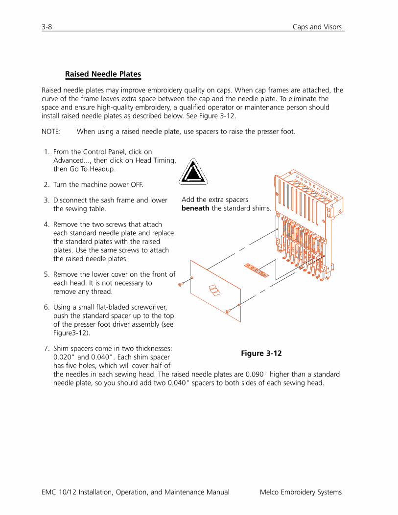
Raised Needle Plates
Raised needle plates may improve embroidery quality on caps. When cap frames are attached, thecurve of the frame leaves extra space between the cap and the needle plate. To eliminate thespace and ensure high-quality embroidery, a qualified operator or maintenance person shouldinstall raised needle plates as described below. See Figure 3-12.
NOTE: When using a raised needle plate, use spacers to raise the presser foot.
1. From the Control Panel, click onAdvanced..., then click on Head Timing,then Go To Headup.
2. Turn the machine power OFF.
3. Disconnect the sash frame and lowerthe sewing table.
4. Remove the two screws that attacheach standard needle plate and replacethe standard plates with the raisedplates. Use the same screws to attachthe raised needle plates.
5. Remove the lower cover on the front ofeach head. It is not necessary toremove any thread.
6. Using a small flat-bladed screwdriver,push the standard spacer up to the topof the presser foot driver assembly (seeFigure3-12).
7. Shim spacers come in two thicknesses:0.020" and 0.040". Each shim spacerhas five holes, which will cover half ofthe needles in each sewing head. The raised needle plates are 0.090" higher than a standardneedle plate, so you should add two 0.040" spacers to both sides of each sewing head.
Figure 3-12
Add the extra spacersbeneath the standard shims.
Caps and Visors 3-9
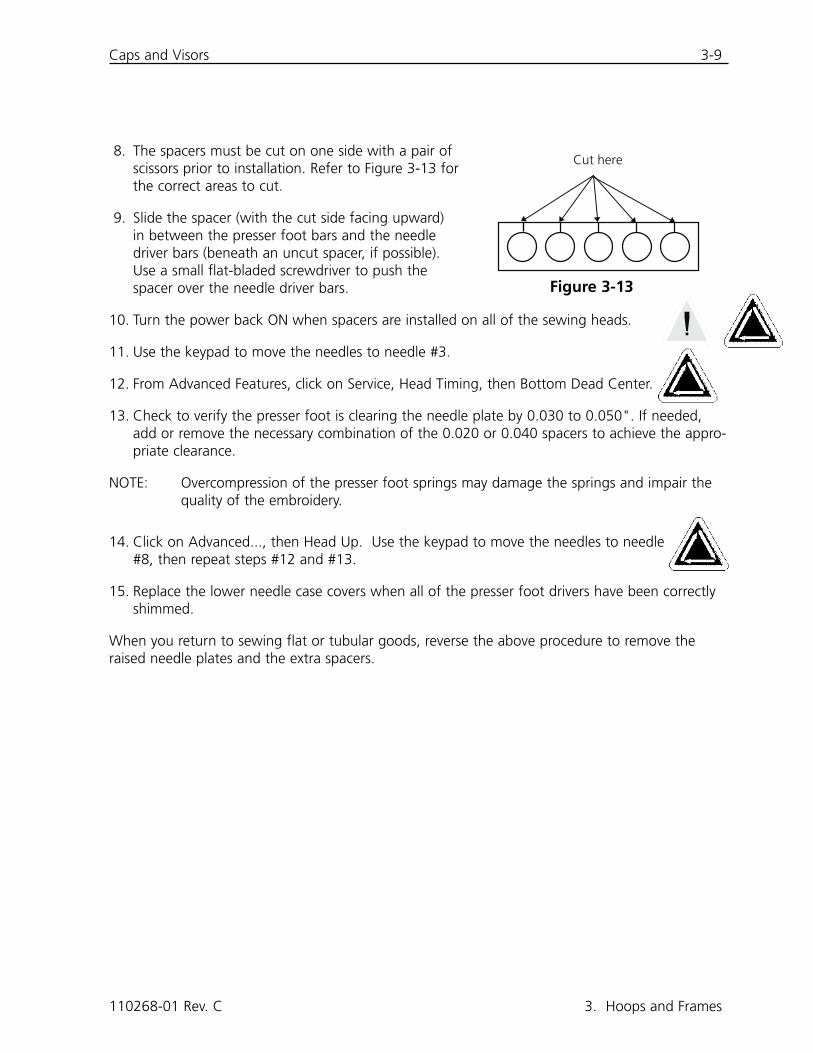
8. The spacers must be cut on one side with a pair ofscissors prior to installation. Refer to Figure 3-13 forthe correct areas to cut.
9. Slide the spacer (with the cut side facing upward)in between the presser foot bars and the needledriver bars (beneath an uncut spacer, if possible).Use a small flat-bladed screwdriver to push thespacer over the needle driver bars.
10. Turn the power back ON when spacers are installed on all of the sewing heads.
11. Use the keypad to move the needles to needle #3.
12. From Advanced Features, click on Service, Head Timing, then Bottom Dead Center.
13. Check to verify the presser foot is clearing the needle plate by 0.030 to 0.050". If needed,add or remove the necessary combination of the 0.020 or 0.040 spacers to achieve the appro-priate clearance.
NOTE: Overcompression of the presser foot springs may damage the springs and impair thequality of the embroidery.
14. Click on Advanced..., then Head Up. Use the keypad to move the needles to needle#8, then repeat steps #12 and #13.
15. Replace the lower needle case covers when all of the presser foot drivers have been correctlyshimmed.
When you return to sewing flat or tubular goods, reverse the above procedure to remove theraised needle plates and the extra spacers.
110268-01 Rev. C 3. Hoops and Frames
Cut here
Figure 3-13

3-10 Caps and Visors
EMC 10/12 Installation, Operation, and Maintenance Manual Melco Embroidery Systems
This page intentionally left blank.

Thread Break Switch 4-1
4. Recovery Methods
This chapter provides information on how to recover from broken threads, missed stitches,mechanical failures, and power outages. Operators and maintenance personnel must attend aMelco approved training course prior to operating or maintaining the machine.
Thread Break Switch
Each head has a thread break switch below the tensioners with
(ON), (AUTO), and (OFF) positions (seeFigure 4-1). The switch controls whether the individual headstitches as it moves through a design. The table below summa-rizes the functions of the switch.
Thread Break Indicator LED
Next to each Thread Break Switch is a yellow LED that signals a thread break (refer to Figure 4-1).When a thread break is detected, the LED on that particular head will be illuminated to showwhere the break is located. A blinking LED indicates an under-thread break while a steadily glow-ing LED indicates an upper-thread break.
110268-01 Rev. C 4. Recovery Methods
Figure 4-1
Setting ResultSews during thread break and framing recovery.Use to restitch an area.Only heads with thread breaks will sew duringthread break recovery or framing. Should beused for normal operation.Disables the sewing head.
4-2 Frame Function
EMC 10/12 Installation, Operation, and Maintenance Manual Melco Embroidery Systems
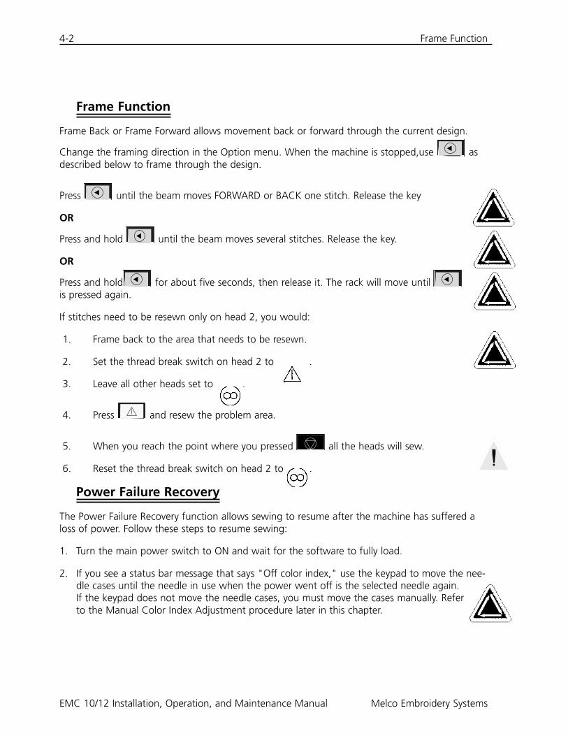
Frame Function
Frame Back or Frame Forward allows movement back or forward through the current design.
Change the framing direction in the Option menu. When the machine is stopped,use asdescribed below to frame through the design.
Press until the beam moves FORWARD or BACK one stitch. Release the key
OR
Press and hold until the beam moves several stitches. Release the key.
OR
Press and hold for about five seconds, then release it. The rack will move until is pressed again.
If stitches need to be resewn only on head 2, you would:
1. Frame back to the area that needs to be resewn.
2. Set the thread break switch on head 2 to .
3. Leave all other heads set to .
4. Press and resew the problem area.
5. When you reach the point where you pressed all the heads will sew.
6. Reset the thread break switch on head 2 to .
Power Failure Recovery
The Power Failure Recovery function allows sewing to resume after the machine has suffered aloss of power. Follow these steps to resume sewing:
1. Turn the main power switch to ON and wait for the software to fully load.
2. If you see a status bar message that says "Off color index," use the keypad to move the nee-dle cases until the needle in use when the power went off is the selected needle again.If the keypad does not move the needle cases, you must move the cases manually. Referto the Manual Color Index Adjustment procedure later in this chapter.
▲▲▲
▲
▲

Manual Color Index Adjustment 4-3
3. If the color index is set correctly, but you see a status bar message that says "Not atheadup," click on Advanced..., then Go To Headup.
4. Click on Advanced..., then Power Failure Recovery.
5. The machine should return to the last stitch made before the power loss and allow you toresume sewing from that point.
NOTE: To maximize your ability to recover from a power loss, designs should be stored on thehard drive, and daily setup should include Hoop Center, Enable Center Design, andAutomatic Return To Origin. Although they are not a part of Power Fail Recovery, thesethree steps will enable you to perform a "manual" recovery if the above procedurefails.
6. If the Power Fail Recover option does not work:
Select Hoop Center, then reload your design. Use the Frame Forward procedure until youreach the last stitch sewn before the power loss and restart at that point. If you know thestitch number, use the Go To Stitch function.
Manual Color Index Adjustment
If the message "Off color index" appears and movingthe needle cases with the keypad has no effect, adjustthe color index manually. A special tool is provided inthe tool kit for this purpose.
1. With the machine power ON and stopped, insertthe index adjustment tool into the hole in the rightside of the color change box (refer to Figure 4-2).
2. Slowly rotate the tool back and forth while watch-ing the LEDs on the front.
3. When one of the LEDs lights up, you are on thecolor index.
110268-01 Rev. C 4. Recovery Methods
Figure 4-2
4-4 Installing a Needle
EMC 10/12 Installation, Operation, and Maintenance Manual Melco Embroidery Systems
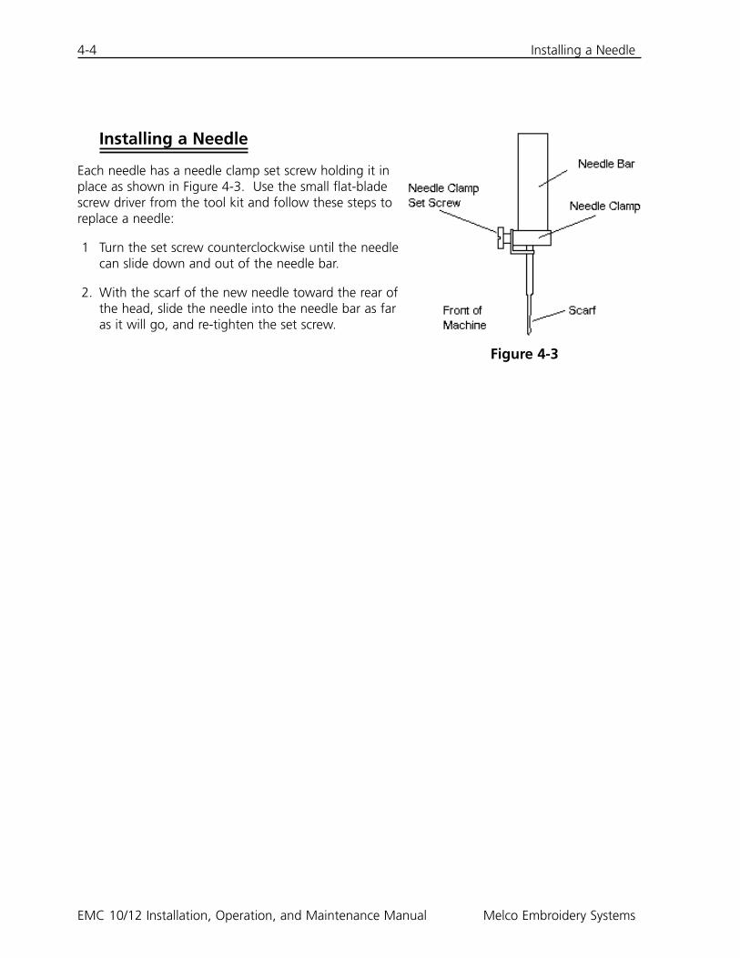
Installing a Needle
Each needle has a needle clamp set screw holding it inplace as shown in Figure 4-3. Use the small flat-bladescrew driver from the tool kit and follow these steps toreplace a needle:
1 Turn the set screw counterclockwise until the needlecan slide down and out of the needle bar.
2. With the scarf of the new needle toward the rear ofthe head, slide the needle into the needle bar as faras it will go, and re-tighten the set screw.
Figure 4-3

Cleaning 5-1
5. Maintenance
This chapter outlines machine maintenance; in addition, maintenance personnel must attend aMelco approved training course prior to maintaining the machine.
Cleaning
Exterior Surfaces
Clean outer plastic surfaces once per month with a soft, clean cloth, a mild detergent and water.Wring out the cloth before wiping the surfaces. Do not get water or any other fluids inside themachine or on any of the working mechanical surfaces.
NOTE: If an accidental spill occurs, turn the machine off then wipe up excess fluid with aclean dry cloth and allow the machine to dry completely before turning the power on.
The Rotary Hook Area
1. Clean this area once per week with the machine power OFF.
2. Remove the 2 needle plate screws and needle plate.
3. Clean the exposed area with the brush supplied in the operator’s kit.
Trimmer Assemblies
1 Clean the trimmer areas once per week with the machine power OFF.
2. Remove the 2 needle plate screws and needle plate.
3. Use a small brush to clear away thread and dust.
Genius Trackball
The trackball in the computer keyboard must be cleaned periodically to ensure maximum perfor-mance. Follow these steps to clean the trackball.
1. Put your fingernails into the grooves on the plastic ring surrounding the ball, and turn coun-terclockwise 45 degrees. The ring will loosen.
2. Turn the trackball upside-down. The ball and ring should come out. Set them aside.
3. Blow out any dirt or lint from the opening using canned air.
4. Use a cotton swab soaked with isopropyl alcohol to clean the rubber rollers.
5. Clean the ball with alcohol and replace it in the housing. Reinstall the ring to secure the ball.
110268-01 Rev. C 5. Maintenance
5-2 Lubrication
EMC 10/12 Installation, Operation, and Maintenance Manual Melco Embroidery Systems
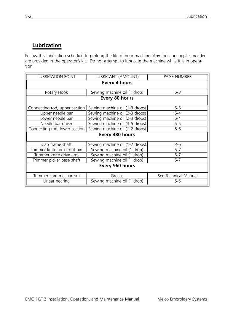
Lubrication
Follow this lubrication schedule to prolong the life of your machine. Any tools or supplies neededare provided in the operator’s kit. Do not attempt to lubricate the machine while it is in opera-tion.
LUBRICATION POINT
Rotary Hook
Connecting rod, upper sectionUpper needle barLower needle barNeedle bar driver
Connecting rod, lower section
Cap frame shaftTrimmer knife arm front pin
Trimmer knife drive armTrimmer picker base shaft
Trimmer cam mechanismLinear bearing
LUBRICANT (AMOUNT)
Sewing machine oil (1 drop)
Sewing machine oil (1-3 drops)Sewing machine oil (2-3 drops)Sewing machine oil (2-3 drops)Sewing machine oil (3-5 drops)Sewing machine oil (1-2 drops)
Sewing machine oil (1-2 drops)Sewing machine oil (1 drop)Sewing machine oil (1 drop)Sewing machine oil (1 drop)
GreaseSewing machine oil (1 drop)
PAGE NUMBER
5-3
5-55-45-45-55-6
3-65-75-75-7
See Technical Manual5-6
Every 4 hours
Every 80 hours
Every 480 hours
Every 960 hours
Lubrication 5-3
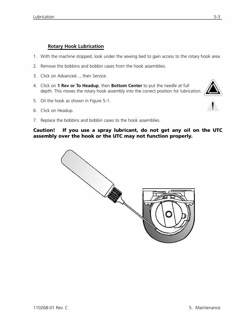
Rotary Hook Lubrication
1. With the machine stopped, look under the sewing bed to gain access to the rotary hook area.
2. Remove the bobbins and bobbin cases from the hook assemblies.
3. Click on Advanced..., then Service.
4. Click on 1 Rev or To Headup, then Bottom Center to put the needle at fulldepth. This moves the rotary hook assembly into the correct position for lubrication.
5. Oil the hook as shown in Figure 5-1.
6. Click on Headup.
7. Replace the bobbins and bobbin cases to the hook assemblies.
Caution! If you use a spray lubricant, do not get any oil on the UTCassembly over the hook or the UTC may not function properly.
110268-01 Rev. C 5. Maintenance
5-4 Lubrication
EMC 10/12 Installation, Operation, and Maintenance Manual Melco Embroidery Systems
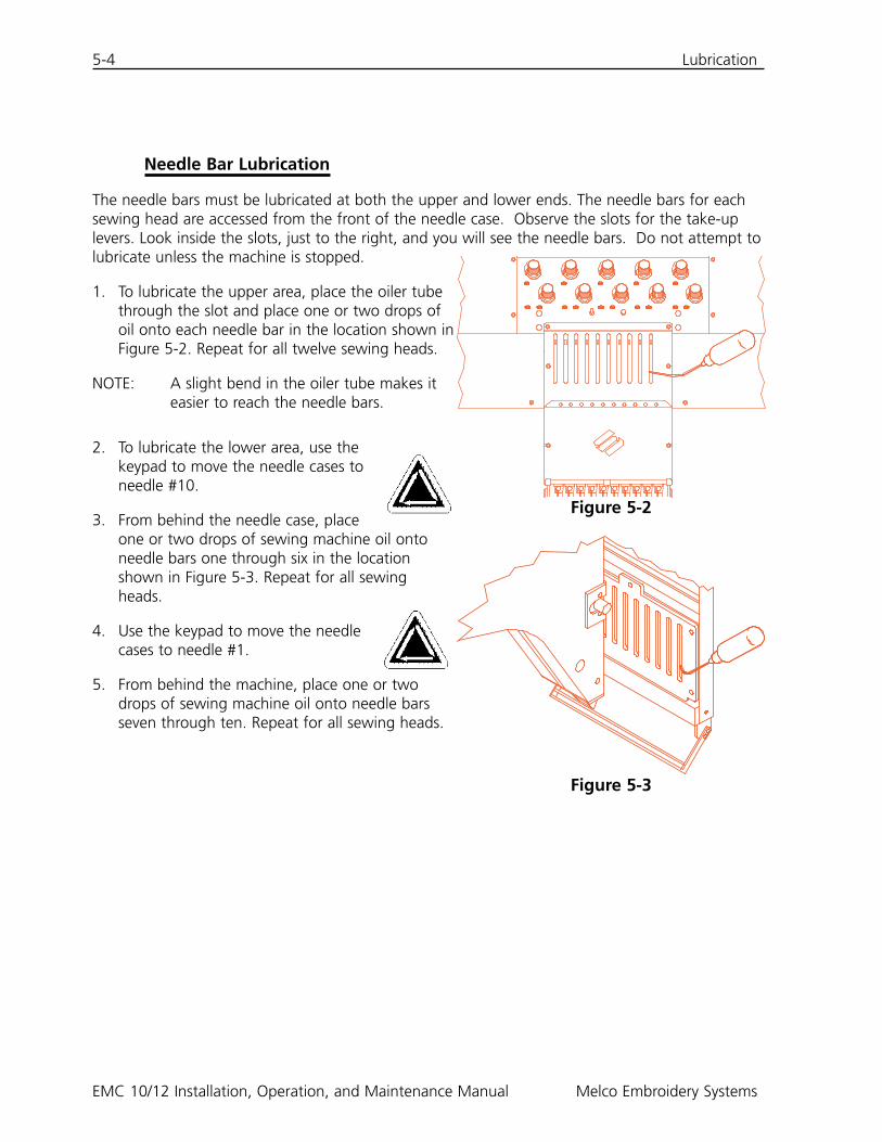
Needle Bar Lubrication
The needle bars must be lubricated at both the upper and lower ends. The needle bars for eachsewing head are accessed from the front of the needle case. Observe the slots for the take-uplevers. Look inside the slots, just to the right, and you will see the needle bars. Do not attempt tolubricate unless the machine is stopped.
1. To lubricate the upper area, place the oiler tubethrough the slot and place one or two drops ofoil onto each needle bar in the location shown inFigure 5-2. Repeat for all twelve sewing heads.
NOTE: A slight bend in the oiler tube makes iteasier to reach the needle bars.
2. To lubricate the lower area, use thekeypad to move the needle cases toneedle #10.
3. From behind the needle case, placeone or two drops of sewing machine oil ontoneedle bars one through six in the locationshown in Figure 5-3. Repeat for all sewingheads.
4. Use the keypad to move the needlecases to needle #1.
5. From behind the machine, place one or twodrops of sewing machine oil onto needle barsseven through ten. Repeat for all sewing heads.
Figure 5-2
Figure 5-3
Lubrication 5-5
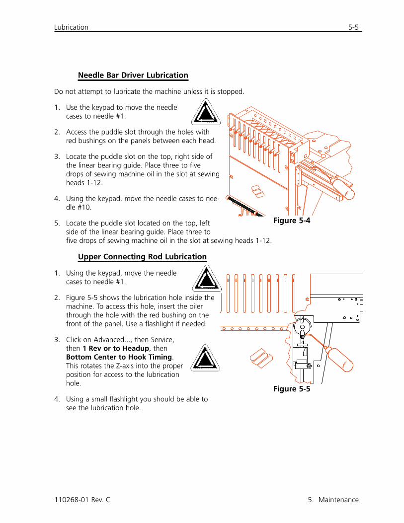
Needle Bar Driver Lubrication
Do not attempt to lubricate the machine unless it is stopped.
1. Use the keypad to move the needlecases to needle #1.
2. Access the puddle slot through the holes withred bushings on the panels between each head.
3. Locate the puddle slot on the top, right side ofthe linear bearing guide. Place three to fivedrops of sewing machine oil in the slot at sewingheads 1-12.
4. Using the keypad, move the needle cases to nee-dle #10.
5. Locate the puddle slot located on the top, leftside of the linear bearing guide. Place three tofive drops of sewing machine oil in the slot at sewing heads 1-12.
Upper Connecting Rod Lubrication
1. Using the keypad, move the needlecases to needle #1.
2. Figure 5-5 shows the lubrication hole inside themachine. To access this hole, insert the oilerthrough the hole with the red bushing on thefront of the panel. Use a flashlight if needed.
3. Click on Advanced..., then Service,then 1 Rev or to Headup, thenBottom Center to Hook Timing.This rotates the Z-axis into the properposition for access to the lubricationhole.
4. Using a small flashlight you should be able tosee the lubrication hole.
110268-01 Rev. C 5. Maintenance
Figure 5-4
Figure 5-5
5-6 Lubrication
EMC 10/12 Installation, Operation, and Maintenance Manual Melco Embroidery Systems
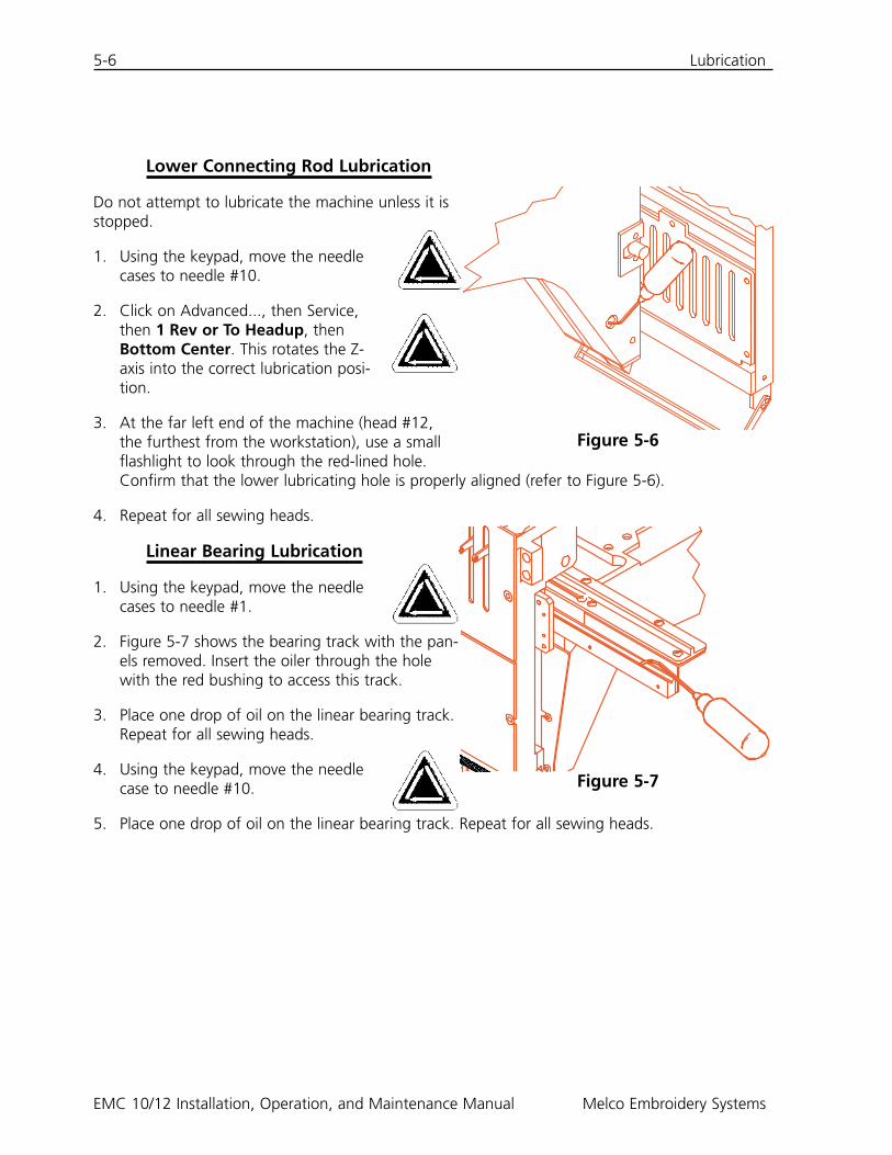
Lower Connecting Rod Lubrication
Do not attempt to lubricate the machine unless it isstopped.
1. Using the keypad, move the needlecases to needle #10.
2. Click on Advanced..., then Service,then 1 Rev or To Headup, thenBottom Center. This rotates the Z-axis into the correct lubrication posi-tion.
3. At the far left end of the machine (head #12,the furthest from the workstation), use a smallflashlight to look through the red-lined hole.Confirm that the lower lubricating hole is properly aligned (refer to Figure 5-6).
4. Repeat for all sewing heads.
Linear Bearing Lubrication
1. Using the keypad, move the needlecases to needle #1.
2. Figure 5-7 shows the bearing track with the pan-els removed. Insert the oiler through the holewith the red bushing to access this track.
3. Place one drop of oil on the linear bearing track.Repeat for all sewing heads.
4. Using the keypad, move the needlecase to needle #10.
5. Place one drop of oil on the linear bearing track. Repeat for all sewing heads.
Figure 5-6
Figure 5-7
Lubrication 5-7
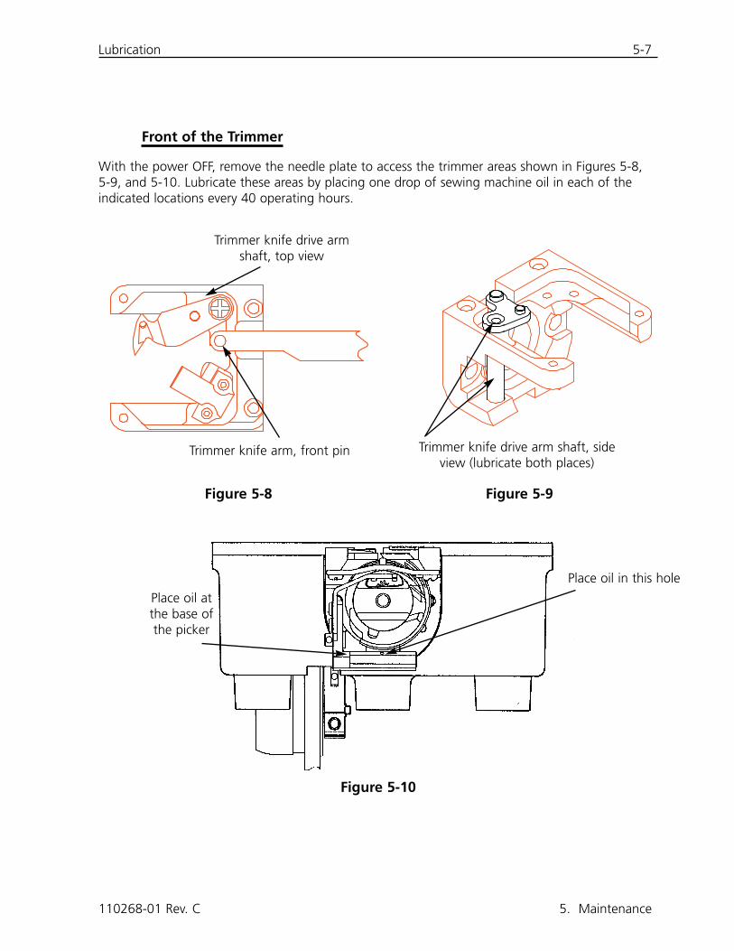
Front of the Trimmer
With the power OFF, remove the needle plate to access the trimmer areas shown in Figures 5-8,5-9, and 5-10. Lubricate these areas by placing one drop of sewing machine oil in each of theindicated locations every 40 operating hours.
110268-01 Rev. C 5. Maintenance
Figure 5-9Figure 5-8
Figure 5-10
Trimmer knife drive armshaft, top view
Trimmer knife arm, front pin Trimmer knife drive arm shaft, sideview (lubricate both places)
Place oil atthe base ofthe picker
Place oil in this hole
5-8 Adjustments
EMC 10/12 Installation, Operation, and Maintenance Manual Melco Embroidery Systems
Trimmer Cam Assembly
The trimmer cam assembly should be lubricated every six months. Refer to the EMC 10/12 techni-cal manual for access to the trimmer cam assembly.
Adjustments
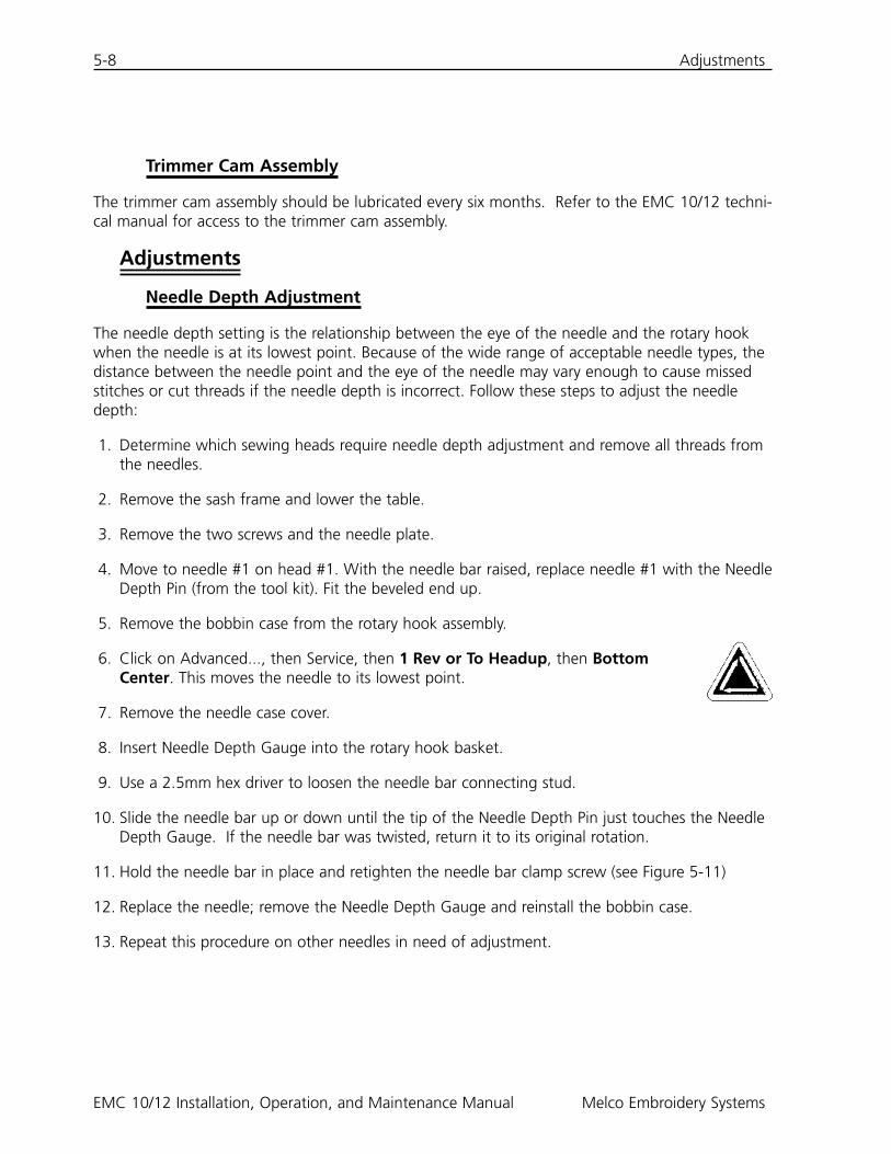
Needle Depth Adjustment
The needle depth setting is the relationship between the eye of the needle and the rotary hookwhen the needle is at its lowest point. Because of the wide range of acceptable needle types, thedistance between the needle point and the eye of the needle may vary enough to cause missedstitches or cut threads if the needle depth is incorrect. Follow these steps to adjust the needledepth:
1. Determine which sewing heads require needle depth adjustment and remove all threads fromthe needles.
2. Remove the sash frame and lower the table.
3. Remove the two screws and the needle plate.
4. Move to needle #1 on head #1. With the needle bar raised, replace needle #1 with the NeedleDepth Pin (from the tool kit). Fit the beveled end up.
5. Remove the bobbin case from the rotary hook assembly.
6. Click on Advanced..., then Service, then 1 Rev or To Headup, then BottomCenter. This moves the needle to its lowest point.
7. Remove the needle case cover.
8. Insert Needle Depth Gauge into the rotary hook basket.
9. Use a 2.5mm hex driver to loosen the needle bar connecting stud.
10. Slide the needle bar up or down until the tip of the Needle Depth Pin just touches the NeedleDepth Gauge. If the needle bar was twisted, return it to its original rotation.
11. Hold the needle bar in place and retighten the needle bar clamp screw (see Figure 5-11)
12. Replace the needle; remove the Needle Depth Gauge and reinstall the bobbin case.
13. Repeat this procedure on other needles in need of adjustment.
Adjustments 5-9
110268-01 Rev. C 5. Maintenance
Figure 5-11
Upper dead stopclamp screw
Needle bar clamp
Needle clamp
5-10 Adjustments
EMC 10/12 Installation, Operation, and Maintenance Manual Melco Embroidery Systems
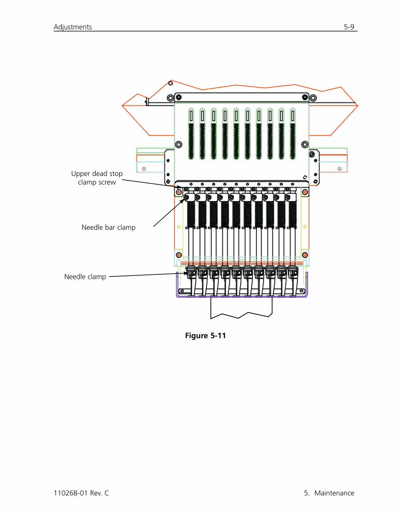
Checking Hook Timing
1. Install a new needle so that the needle/hook point posi-tioning can be better evaluated.
2. Remove the two screws and the needle plate.
3. Click on Advanced..., the Service, then 1 Revor To Headup.
4. Click on Bottom Center, then click on HookTiming. Verify that degrees equal 201 on thescreen.
The hook point must align directly behind the needle with a0.002 to 0.008" gap (refer to Figure 5-12).
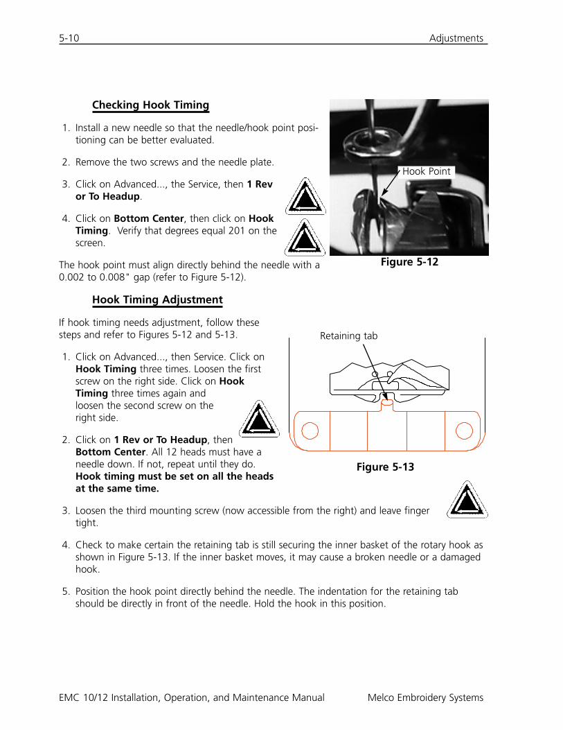
Hook Timing Adjustment
If hook timing needs adjustment, follow thesesteps and refer to Figures 5-12 and 5-13.
1. Click on Advanced..., then Service. Click onHook Timing three times. Loosen the firstscrew on the right side. Click on HookTiming three times again andloosen the second screw on theright side.
2. Click on 1 Rev or To Headup, thenBottom Center. All 12 heads must have aneedle down. If not, repeat until they do.Hook timing must be set on all the headsat the same time.
3. Loosen the third mounting screw (now accessible from the right) and leave fingertight.
4. Check to make certain the retaining tab is still securing the inner basket of the rotary hook asshown in Figure 5-13. If the inner basket moves, it may cause a broken needle or a damagedhook.
5. Position the hook point directly behind the needle. The indentation for the retaining tabshould be directly in front of the needle. Hold the hook in this position.
Figure 5-13
Figure 5-12
Hook Point
Retaining tab
Adjustments 5-11
6. Slide the hook assembly forward or backward until you have a 0.002 to 0.008" gap betweenit and the needle (as described previously).
7. When the gap is correct, tighten the screws. Use the Hook Timing command as explained insteps one and two in order to access all the screws.
8. Click on 1 Rev or To Headup.
9. Click on Bottom Center, then Hook Timing.
10. Check all of your adjustments and repeat any steps if necessary.
11. Replace the needle plate, making certain the needle is centered in the needle platehole. When the needle is centered hold the plate in position, and tighten completely.
Adjusting UTCs
1. Click on Bottom Dead Center.
2. Set the UTC retaining finger 0.8mm away from the sewing hook basket and centerthe retaining finger to the needle. Tighten the UTC fastener screws.
3. Using the UTC adjusting screws, position the UTC sensor arm 0.020" (0.5mm) from the nee-dle.
4. Manually disengage the needle bar from the reciprocator.
5. Disconnect the linkage to the movable knife arm pivot.
6. Position the movable knife across the sensor arm. There should be 0.004" (0.1mm) clearance.
7. Reattach the linkage to the movable knife arm pivot.
8. Place the needle plate on the hook support. Looking from the front, see if the UTC sensor armtouches the needle plate. If it touches, support the lowest section of the sensor arm with aflat-blade screwdriver, then push down the sensor arm while maintaining the clearance overthe knife.
110268-01 Rev. C 5. Maintenance
5-12 Adjustments
EMC 10/12 Installation, Operation, and Maintenance Manual Melco Embroidery Systems
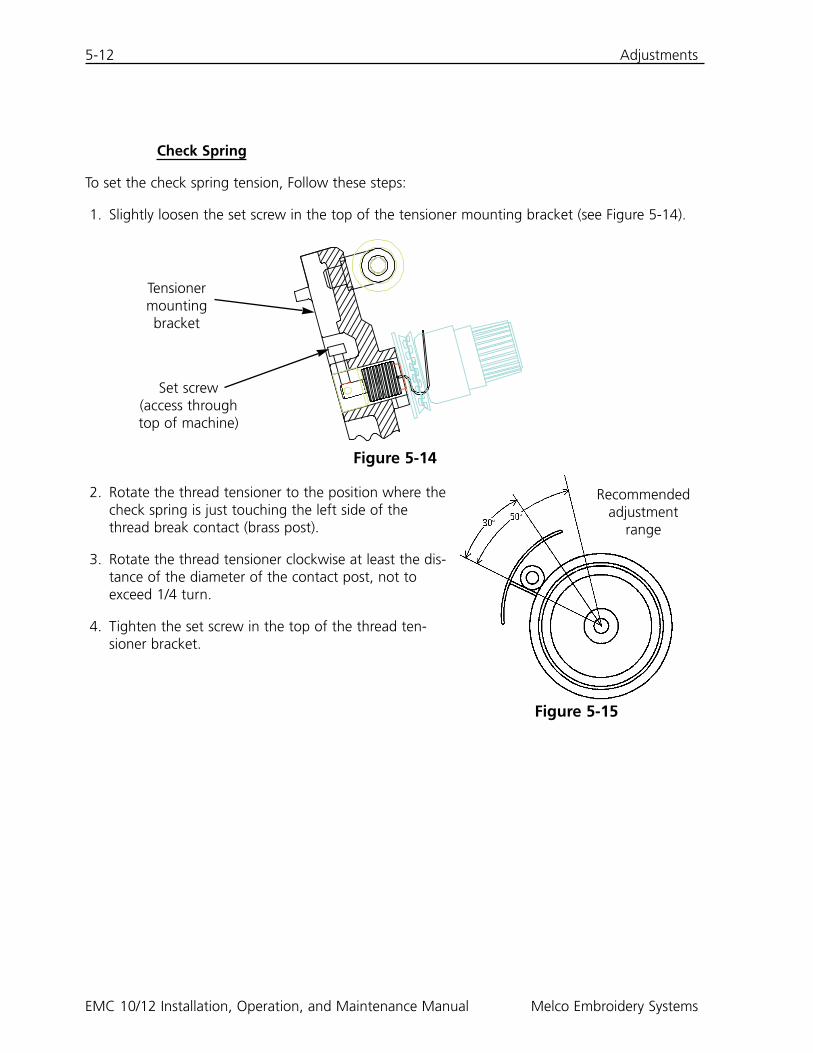
Check Spring
To set the check spring tension, Follow these steps:
1. Slightly loosen the set screw in the top of the tensioner mounting bracket (see Figure 5-14).
2. Rotate the thread tensioner to the position where thecheck spring is just touching the left side of thethread break contact (brass post).
3. Rotate the thread tensioner clockwise at least the dis-tance of the diameter of the contact post, not toexceed 1/4 turn.
4. Tighten the set screw in the top of the thread ten-sioner bracket.
Figure 5-14
Set screw(access throughtop of machine)
Tensionermountingbracket
Figure 5-15
Recommendedadjustment
range
Replacement Parts 5-13
Replacement Parts
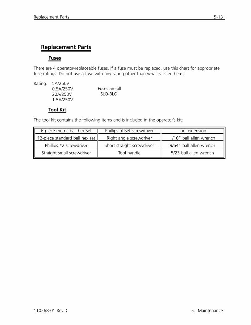
Fuses
There are 4 operator-replaceable fuses. If a fuse must be replaced, use this chart for appropriatefuse ratings. Do not use a fuse with any rating other than what is listed here:
Rating: 5A/250V0.5A/250V20A/250V1.5A/250V
Tool Kit
The tool kit contains the following items and is included in the operator’s kit:
110268-01 Rev. C 5. Maintenance
6-piece metric ball hex set
12-piece standard ball hex set
Phillips #2 screwdriver
Straight small screwdriver
Phillips offset screwdriver
Right angle screwdriver
Short straight screwdriver
Tool handle
Tool extension
1/16” ball allen wrench
9/64” ball allen wrench
5/23 ball allen wrench
Fuses are allSLO-BLO.
5-14 Replacement Parts
EMC 10/12 Installation, Operation, and Maintenance Manual Melco Embroidery Systems
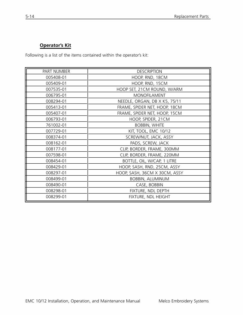
Operator’s Kit
Following is a list of the items contained within the operator’s kit:
PART NUMBER005408-01005409-01007535-01006795-01008294-01005413-01005407-01006793-01761002-01007729-01008374-01008162-01008177-01007598-01008454-01008429-01008297-01008499-01008490-01008298-01008299-01
DESCRIPTIONHOOP, RND, 18CMHOOP, RND, 15CM
HOOP SET, 21CM ROUND, W/ARMMONOFILAMENT
NEEDLE, ORGAN, DB X K5, 75/11FRAME, SPIDER NET, HOOP, 18CMFRAME, SPIDER NET, HOOP, 15CM
HOOP, SPIDER, 21CMBOBBIN, WHITE
KIT, TOOL, EMC 10/12SCREW/NUT, JACK, ASSY
PADS, SCREW, JACKCLIP, BORDER, FRAME, 300MMCLIP, BORDER, FRAME, 220MM
BOTTLE, OIL, W/CAP, 1 LITREHOOP, SASH, RND, 25CM, ASSY
HOOP, SASH, 36CM X 30CM, ASSYBOBBIN, ALUMINUM
CASE, BOBBINFIXTURE, NDL DEPTHFIXTURE, NDL HEIGHT
Replacement Parts 5-15
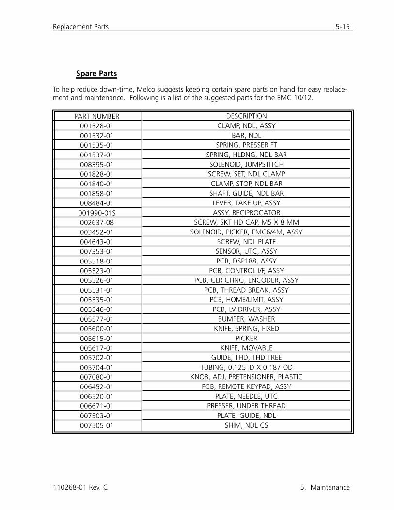
Spare Parts
To help reduce down-time, Melco suggests keeping certain spare parts on hand for easy replace-ment and maintenance. Following is a list of the suggested parts for the EMC 10/12.
110268-01 Rev. C 5. Maintenance
PART NUMBER001528-01001532-01001535-01001537-01008395-01001828-01001840-01001858-01008484-01001990-01S002637-08003452-01004643-01007353-01005518-01005523-01005526-01005531-01005535-01005546-01005577-01005600-01005615-01005617-01005702-01005704-01007080-01006452-01006520-01006671-01007503-01007505-01
DESCRIPTIONCLAMP, NDL, ASSY
BAR, NDLSPRING, PRESSER FT
SPRING, HLDNG, NDL BARSOLENOID, JUMPSTITCHSCREW, SET, NDL CLAMPCLAMP, STOP, NDL BARSHAFT, GUIDE, NDL BARLEVER, TAKE UP, ASSYASSY, RECIPROCATOR
SCREW, SKT HD CAP, M5 X 8 MMSOLENOID, PICKER, EMC6/4M, ASSY
SCREW, NDL PLATESENSOR, UTC, ASSYPCB, DSP188, ASSY
PCB, CONTROL I/F, ASSYPCB, CLR CHNG, ENCODER, ASSY
PCB, THREAD BREAK, ASSYPCB, HOME/LIMIT, ASSYPCB, LV DRIVER, ASSY
BUMPER, WASHERKNIFE, SPRING, FIXED
PICKERKNIFE, MOVABLE
GUIDE, THD, THD TREETUBING, 0.125 ID X 0.187 OD
KNOB, ADJ, PRETENSIONER, PLASTICPCB, REMOTE KEYPAD, ASSY
PLATE, NEEDLE, UTCPRESSER, UNDER THREAD
PLATE, GUIDE, NDLSHIM, NDL CS
5-16 Replacement Parts
EMC 10/12 Installation, Operation, and Maintenance Manual Melco Embroidery Systems
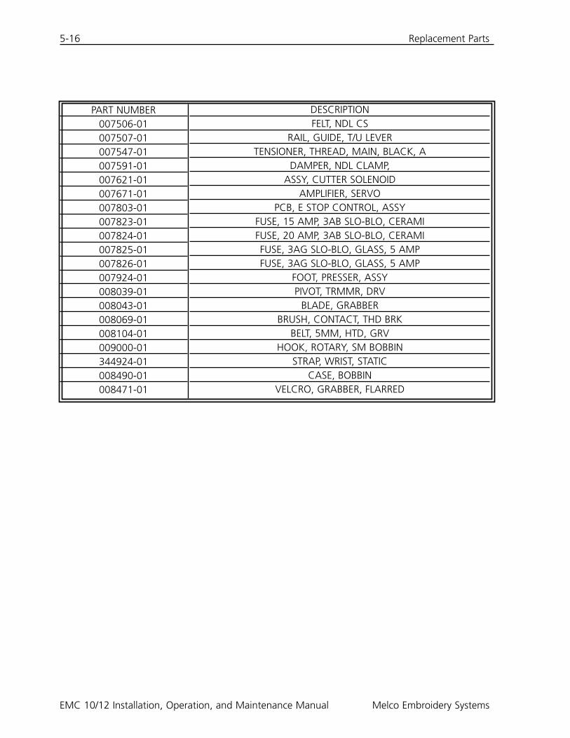
PART NUMBER007506-01007507-01007547-01007591-01007621-01007671-01007803-01007823-01007824-01007825-01007826-01007924-01008039-01008043-01008069-01008104-01009000-01344924-01008490-01008471-01
DESCRIPTIONFELT, NDL CS
RAIL, GUIDE, T/U LEVERTENSIONER, THREAD, MAIN, BLACK, A
DAMPER, NDL CLAMP,ASSY, CUTTER SOLENOID
AMPLIFIER, SERVOPCB, E STOP CONTROL, ASSY
FUSE, 15 AMP, 3AB SLO-BLO, CERAMIFUSE, 20 AMP, 3AB SLO-BLO, CERAMIFUSE, 3AG SLO-BLO, GLASS, 5 AMPFUSE, 3AG SLO-BLO, GLASS, 5 AMP
FOOT, PRESSER, ASSYPIVOT, TRMMR, DRV
BLADE, GRABBERBRUSH, CONTACT, THD BRK
BELT, 5MM, HTD, GRVHOOK, ROTARY, SM BOBBIN
STRAP, WRIST, STATICCASE, BOBBIN
VELCRO, GRABBER, FLARRED
Troubleshooting Guide 6-1
6. Troubleshooting Guide
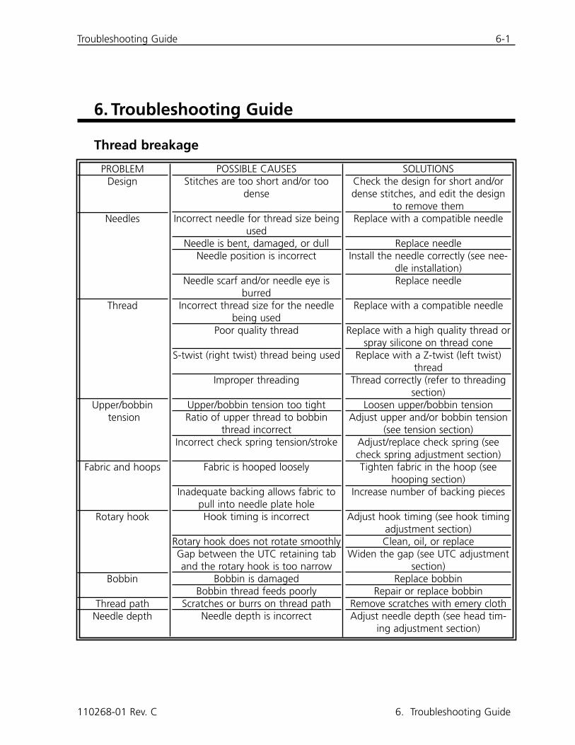
Thread breakage
110268-01 Rev. C 6. Troubleshooting Guide
PROBLEMDesign
Needles
Thread
Upper/bobbintension
Fabric and hoops
Rotary hook
Bobbin
Thread pathNeedle depth
POSSIBLE CAUSESStitches are too short and/or too
dense
Incorrect needle for thread size beingused
Needle is bent, damaged, or dullNeedle position is incorrect
Needle scarf and/or needle eye isburred
Incorrect thread size for the needlebeing used
Poor quality thread
S-twist (right twist) thread being used
Improper threading
Upper/bobbin tension too tightRatio of upper thread to bobbin
thread incorrectIncorrect check spring tension/stroke
Fabric is hooped loosely
Inadequate backing allows fabric topull into needle plate holeHook timing is incorrect
Rotary hook does not rotate smoothlyGap between the UTC retaining taband the rotary hook is too narrow
Bobbin is damagedBobbin thread feeds poorly
Scratches or burrs on thread pathNeedle depth is incorrect
SOLUTIONSCheck the design for short and/ordense stitches, and edit the design
to remove themReplace with a compatible needle
Replace needleInstall the needle correctly (see nee-
dle installation)Replace needle
Replace with a compatible needle
Replace with a high quality thread orspray silicone on thread cone
Replace with a Z-twist (left twist)thread
Thread correctly (refer to threadingsection)
Loosen upper/bobbin tensionAdjust upper and/or bobbin tension
(see tension section)Adjust/replace check spring (seecheck spring adjustment section)Tighten fabric in the hoop (see
hooping section)Increase number of backing pieces
Adjust hook timing (see hook timingadjustment section)Clean, oil, or replace
Widen the gap (see UTC adjustmentsection)
Replace bobbinRepair or replace bobbin
Remove scratches with emery clothAdjust needle depth (see head tim-
ing adjustment section)
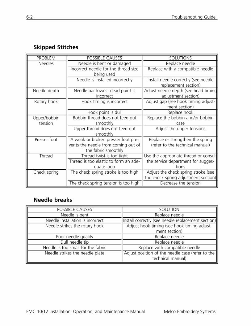
Skipped Stitches
Needle breaks
6-2 Troubleshooting Guide
EMC 10/12 Installation, Operation, and Maintenance Manual Melco Embroidery Systems
PROBLEMNeedles
Needle depth
Rotary hook
Upper/bobbin tension
Presser foot
Thread
Check spring
POSSIBLE CAUSESNeedle is bent or damaged
Incorrect needle for the thread sizebeing used
Needle is installed incorrectly
Needle bar lowest dead point is incorrect
Hook timing is incorrect
Hook point is dullBobbin thread does not feed out
smoothlyUpper thread does not feed out
smoothlyA weak or broken presser foot pre-
vents the needle from coming out ofthe fabric smoothly
Thread twist is too tightThread is too elastic to form an ade-
quate loopThe check spring stroke is too high
The check spring tension is too high
SOLUTIONSReplace needle
Replace with a compatible needle
Install needle correctly (see needlereplacement section)
Adjust needle depth (see head timingadjustment section)
Adjust gap (see hook timing adjust-ment section)Replace hook
Replace the bobbin and/or bobbincase
Adjust the upper tensions
Replace or strengthen the spring(refer to the technical manual)
Use the appropriate thread or consultthe service department for sugges-
tionsAdjust the check spring stroke (see
the check spring adjustment section)Decrease the tension
POSSIBLE CAUSESNeedle is bent
Needle installation is incorrectNeedle strikes the rotary hook
Poor needle qualityDull needle tip
Needle is too small for the fabricNeedle strikes the needle plate
SOLUTIONReplace needle
Install correctly (see needle replacement section)Adjust hook timing (see hook timing adjust-
ment section)Replace needleReplace needle
Replace with compatible needleAdjust position of the needle case (refer to the
technical manual)
Troubleshooting Guide 6-3
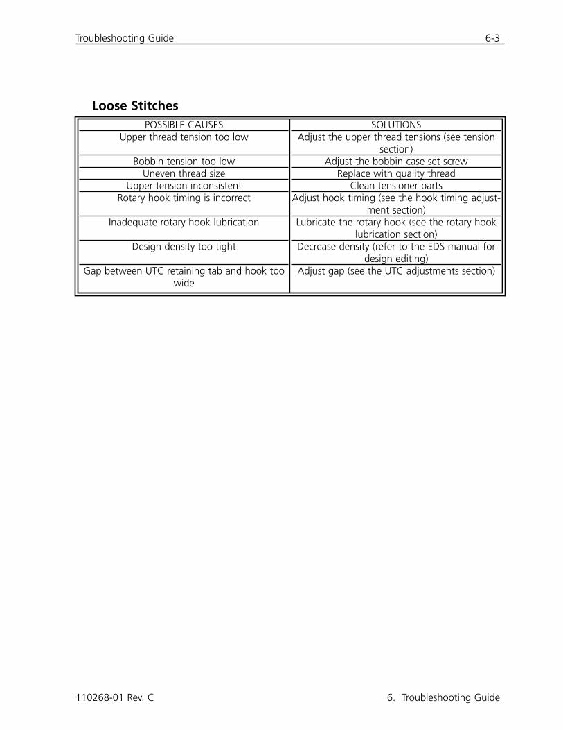
Loose Stitches
110268-01 Rev. C 6. Troubleshooting Guide
POSSIBLE CAUSESUpper thread tension too low
Bobbin tension too lowUneven thread size
Upper tension inconsistentRotary hook timing is incorrect
Inadequate rotary hook lubrication
Design density too tight
Gap between UTC retaining tab and hook toowide
SOLUTIONSAdjust the upper thread tensions (see tension
section)Adjust the bobbin case set screw
Replace with quality threadClean tensioner parts
Adjust hook timing (see the hook timing adjust-ment section)
Lubricate the rotary hook (see the rotary hooklubrication section)
Decrease density (refer to the EDS manual fordesign editing)
Adjust gap (see the UTC adjustments section)
6-4 Troubleshooting Guide
EMC 10/12 Installation, Operation, and Maintenance Manual Melco Embroidery Systems
This page intentionally left blank.
Status Messages 7-1
7. Status Messages
Control Panel Messages
Frame Forward/Backward: The machine is currently framing forward or backward.
In test mode: The test mode (set via the Test Mode dialog box) is active.
Machine error: This is a general error message - the specific error will be displayed on the statusbar message area.
Machine Idle: The machine is ready, but not currently sewing.
Machine Running: The machine is currently operating.
Stopped -- bobbin break, head #: The machine has stopped sewing due to a bobbin threadbreak at a specified head.
Stopped -- color change: The machine is waiting for a manually-specified color.
Stopped -- thread break, head #: The machine has stopped sewing due to a thread break at aspecified head.
Stopped -- waiting for start key: The machine has been stopped during sewing and is waitingto resume.
Status Bar Messages
Color change time out: The color change did not occur within the software-specified time limit.Reset the color index.
Controller memory cleared: After a manual reset, this confirms that the controller has beenreset and is ready to sew.
End of design: The sewout is finished.
Fault intr, no bits set: Internal error - call Customer Service for advice.
Grabber not home: The grabber is not in home position, or not retracted completely.
Insufficient memory for the requested operation: The operator has tried to load a design thatis too large for the system memory.
Learn color change: The machine is waiting for a manually-specified color.
110268-01 Rev. C 7. Status Messages
7-2 Status Messages
EMC 10/12 Installation, Operation, and Maintenance Manual Melco Embroidery Systems
No design ready: You must load a design before pressing the start button.
Not at headup: Z-axis is not at the Headup position. Go to the Head Timing menu and reset theHeadup position manually.
Off color index: This may occur during initial power up. See Section 6, Recovery Methods, for anexplanation of how to reset the color index.
Outside of hoop: The design loaded is too large for the specified hoop, or the sash has beenmanually moved past the hoop limits.
Sign on completed: The machine and controller are ready to sew.
Thread break: A thread has broken - refer to the Control Panel message area.
Thread grabber time out: The thread grabber did not function within the software-specifiedtime limit. Free the grabber and retract it. If this does not work, call for factory advice.
Trimmer disabled: The trimmer has been disabled in the Options dialog box.
Trimmer not home: The trimmer is not in its home position, or has not retracted completely.
X motor fault: Check motor driver card or call for factory-authorized service.
X over current: Check motor driver card or call for factory-authorized service.
X over voltage: Check motor driver card or call for factory-authorized service.
X under voltage: Check motor driver card or call for factory-authorized service.
XY home not set: The operator tried to move the sash without home being set.
XY rack limit error: The sash has been moved past the normal X/Y limits.
XY racks not done: The X or Y cycle was not completed. Press start to reset.
Y motor fault: Check motor driver card or call for factory-authorized service.
Y over current: Check motor driver card or call for factory-authorized service.
Y over voltage: Check motor driver card or call for factory-authorized service.
Y under voltage: Check motor driver card or call for factory-authorized service.
Status Messages 7-3
Z timeout error: This may indicate either the Z timing cycle was not completed, or that the Zmotor may be failing. If sewing does not resume after pressing the Start button again, call for fac-tory advice.
Z motor fault: Check motor driver card or call for factory-authorized service.
Z over current: Check motor driver card or call for factory-authorized service.
Z over voltage: Check motor driver card or call for factory-authorized service.
Z tracking error: Internal error - call Customer Service for advice.
Z under voltage: Check motor driver card or call for factory-authorized service.
110268-01 Rev. C 7. Status Messages

7-4 Status Messages
EMC 10/12 Installation, Operation, and Maintenance Manual Melco Embroidery Systems
This page intentionally left blank.
Glossary of Terms 8-1
8. Glossary of Embroidery Terms
A
ACTIVE WINDOWThe window that you are currently using. Also called the current window.
ALPHABETSLettering styles that are ready to use for embroidery. Alphabets can also be designs that arebrought to the screen using letters of the alphabet. An example of this would be Sports Symbols.
APPLICATION WINDOWThe first window to appear when EDS III is opened. The Application Window has three menu baritems; File, Peripheral, and Help.
APPLIQUEThe art of using fabrics to enhance a design or to reduce the stitch count.
ARTWORKA design or cartoon used to digitize.
AUTO DELETEAn option that automatically deletes designs from the sewing peripheral after the design hassewn once.
AUTO RUNAn option that automatically sends a design to the beginning of the job queue, allowing you tosew without making any selections from the peripheral menus.
AUTO TRIMAn option that automatically inserts a trim command between each alphabet letter used in adesign.
ARC ANGLEThe center of lettering sewn on a circle. This position is given in degrees, 0É at the top of the cir-cle,180É at the bottom.
ARC FROM CENTERWhen the position of the needle prior to sewing is at the center of the circle. The distance fromthe center of the circle to the bottom of the lettering is the radius.
ARC NORMALWhen the position of the needle prior to sewing is on the circumference of the circle.
ASDThe file extension given by EDS III to a design that is sent to the peripheral.
110268-01 Rev. C 8. Glossary of Embroidery Terms
8-2 Glossary of Terms
EMC 10/12 Installation, Operation, and Maintenance Manual Melco Embroidery Systems
B
BACKINGFabric used for stabilizing that is added to the back of a garment to be embroidered.
BEAN STITCHA form of running stitch where the stitch is made forward, then back to the original needle pene-tration point, then forward again. Also known as a triple run.
BIRD NESTA tangled mass of thread that gets jammed in the needle plate. Sometimes it is caused by improp-er tensions.
BIT PADAnother name for a Digitizing Tablet.
BLOCKA designated group of stitches that can be scaled, rotated, repositioned, deleted, cut, copied andpasted.
BLOCK EDITThe term used for changing a defined group of stitches.
BOBBINThe reel or spool that holds the under thread of machine sewing. The under thread itself.
C
CENTER DESIGNPositing the design in the center of the sewing field.
CHAIN STITCHA stitch used to outline and detail a chenille design.
CHENILLEA form of embroidery with a deep pile that uses heavy yarns and has no bobbin thread.Commonly used for high school letter jackets.
CLICKPressing and releasing a mouse button in one quick motion.
CLIPBOARDA temporary storage area in the computer's memory. Data in the storage area can be copied toanother place.
CNDThe three letter extension given to a Condensed file. See Condensed Format for more informa-tion.
Glossary of Terms 8-3
COLUMN FILLAn option to turn wide column or satin stitches into a series of shorter stitches.
COLUMN STITCHA stitch formed with one needle penetration on either side of a column. Also referred to as a satinstitch or a steil stitch.
COLUMN WIDTHThe width of the actual side-to-side needle penetrations in a column or satin stitch. In EDS III, thewidth can be increased or decreased in increments of 10% from 90% to -90%.
COMPLEX FILLA method for digitizing fills where the computer automatically determines the various indepen-dent segments that are required in making the complete fill of an irregular shape.
CONDENSED FORMATA coding format that includes only the data for the Mk entries and function commands createdduring digitizing. This format allows you to scale the design up or down as well as change thedensity and stitch length of the design.
COPYA command that keeps the design in the current window and also stores it in a temporary memo-ry called the clipboard.
CURSORAn icon used to indicate your position on the computer screen.
CUTAn editing function used to take selected stitching out of a design and store it in the clipboard.From there it may be pasted to a different place.
D
DATASETA basic set of instructions to produce an embroidery design.
DEFAULTSValues that are automatically used unless you override them with different values.
DENSITYThe vertical distance between two lines of stitching, measured in points.
DESIGN FILEAny design stored on your hard disk or floppy disk. A file name can have up to eight letters, aperiod, and a three letter extension.
110268-01 Rev. C 8. Glossary of Embroidery Terms
8-4 Glossary of Terms
EMC 10/12 Installation, Operation, and Maintenance Manual Melco Embroidery Systems
DIALOG BOXA box displayed on your computer screen that prompts you to give information, such as a selec-tion from a list of options, or a file name.
DIGITIZINGConverting artwork into a series of commands that can be read by an embroidery machine withthe use of a special device.
DIGITIZING TABLETA board used to communicate with a computer or an embroidery machine while creating adesign.
DIGITRACThe original Melco computerized digitizing system which uses an exceptionally large surface andits own vertical stand.
DIRECTORYA named group of computer files stored on one of your computer drives. The hard drive of yourcomputer is usually the C directory. Floppy diskettes are inserted into the A or B drive.
DISKA computer data storage device which is accessed in the hard drive or one of the floppy drives.
DISKETTE FORMATThe manner in which a disk has been prepared to accept information.
DITHERED COLORSA combination of a solid color and a pattern.
DOUBLE CLICKPressing the mouse button quickly two times.
DRAGHolding down the mouse button while moving the mouse. This is usually done to move an objecton the screen or to highlight text.
DROP-DOWN MENUA list of available commands that displays when you click on a menu option. Commands displayedin black are accessible, commands that are displayed in gray or half tone are not.
E
EDITChanging a design file by adding, deleting or moving Mk points, or by inserting and deletingfunctions.
EMBROIDERY POINTA unit of measure equal to one tenth of a millimeter or 1/254th of an inch.
Glossary of Terms 8-5
EXPThe three letter extension given to an Expanded file.
EXPANDED FORMATA coding format that includes the data for every stitch in the design.
EXPORTCopying a design from the computer to a non-DOS format diskette or paper tape.
EXTENSIONSThe last part of a file name after the period. It can be up to three characters long and is used toidentify the type of file.
F
FILEA related collection of information, named and often stored on a disk.
FILE NAMEThe unique identifier given to a design that is stored on a computer. The file name can have up toeight characters, a period, and an up to three letters extension.
FILL STITCHA series of running stitches used to cover large areas.
FORMATPreparing a disk to receive information. All new disks must be formatted, but reformatting a diskdestroys any information stored on it.
FUNCTIONAn action caused by a command in a design such as Trim, Color Change, Needle Up, etc.
G
GRAPHICAL ROTATIONAngling a design in the Layout window using the mouse to click and drag the rotation boxaround the object.
GRAPHICAL SCALINGMaking a design larger or smaller in the Layout window using the mouse in a click and dragmotion.
GROUP OBJECTSObjects that have been locked together on the screen.
110268-01 Rev. C 8. Glossary of Embroidery Terms
8-6 Glossary of Terms
EMC 10/12 Installation, Operation, and Maintenance Manual Melco Embroidery Systems
H
HARD DISKA sealed area in your computer with a read/write head and auxiliary memory.
HOOPA device made of wood, metal, or plastic used to hold a garment or fabric taut during theembroidery process.
HORIZONTAL SPACINGAdditional spacing that may be added between Alphabet letters.
I
ICONA small graphic representation of something larger.
IMPORTBringing a design file into the EDS III program from a non-DOS formatted diskette or paper tape.
INSERTAdding additional information to an existing design.
J
JUMP STITCHA frame movement without a needle penetration. It function allows you to make a stitch longerthan the maximum stitch length of your machine.
L
LAYER BY COLORUsed to show specific colors of a design on the computer screen.
LAYOUT WINDOWThe screen in which you can digitize designs, open files on the hard disk, import designs fromfloppy disks, export designs, modify designs, and create lettering.
LETTER WIDTHThe overall width of each letter, NOT the column width. In EDS III changes to letter width can bemade in increments of 10% from +30% to -30%.
LINE CENTER BOTTOMWhen lettering is centered horizontally and above the position of the needle prior to sewing.
LINE CENTER MIDDLEWhen lettering is centered horizontally and vertically from the position of the needle prior tosewing.

Glossary of Terms 8-7
LINE NORMALWhen the bottom left of the lettering is the needle position prior to sewing. The sewing will stopat the bottom right and will not return to the original position.
LINE SPACINGAdding space between lines of lettering. Line space is determined by adding the letter height tothe amount of blank space you want between the lines.
LIST BOXA box, usually with a scroll bar, that appears within a dialog box and displays available options.
LOAD FILLAccessing a fill pattern for inspection or changes.
LOCK GROUPOne or more objects that have been joined together.
LOCK STITCHThree or more stitches placed closely together to prevent the embroidered stitches from pullingout. Also know as a tie-off stitch.
M
MAXIMIZEThe small button to the right of the Title Bar with the up arrow. Used to enlarge a window to itsfullest extent.
MAXIMUM STITCH LENGTHThe longest stitch your embroidery machine is capable of sewing before performing a jump stitch.The maximum stitch length for Melco is 127 pts.
MINIMIZEThe small button on the right of the Title Bar with the down arrow. Used to reduce a window toan icon.
MODIFY MK BUTTONAn option that changes the position of a Mk point or changes the Mk to a different type of Mk.
MOSS STITCHThe "loopy" part of a chenille design. The height of the loop is controlled by the height of theneedle.
MULTIHEADAn embroidery machine with more than one sewing head.
110268-01 Rev. C 8. Glossary of Embroidery Terms
8-8 Glossary of Terms
EMC 10/12 Installation, Operation, and Maintenance Manual Melco Embroidery Systems
N
NEEDLE UPA command used to move from one part of a design to another without stitching.
NON-DOS FORMATSAny disk format other than DOS that is supported by EDS III, such as: Melco, Tajima, Barudan,ZSK.
NORMAL STITCHA command that resets the stitching to a regular running stitch. It also brings the needle down tothe sewing position after a needle-up function is performed.
O
OBJECTAny design from a disk, paper tape, or lettering brought in to the Layout window. Several objectscan be in one window at one time.
OBJECT FILEA code format where each object has its own separate set of parameters. Condensed, expandedand lettering designs can all be saved together as an Object File.
OBJECT ORDERA list showing the sewing order of a group of objects.
OBJECT PARAMETERSA dialog box which allows you to change the scale, rotation, orientation, or lock status of anobject.
OFMThe three letter extension that identifies an Object file.
ORIENTATIONThe direction that a design will sew. Melco uses an "F" to designate a normal sewing position.
ORIGINThe point at which a design will start. Most designs will have x and y coordinates of 0,0; meaningthat the design will start in the center and end in the center.
P
PAPER TAPEAn older form of computer information storage in which the information is stored as a series ofholes on a reel-to-reel paper tape.
PARTITION LINE SEQUENCEDetermines where the needle will penetrate on each line of stitching in a fill stitch.
Glossary of Terms 8-9
PERIPHERALAny device that is attached to or run by the computer: Embroidery Machines, Paper Tape Punches,Digitizing Tablets, Printers, or Plotters.
PERIPHERAL SETUPA dialog box that allows you to select Embroidery Peripherals in your network.
PERIPHERAL STATUSA dialog box that displays information about a particular peripheral.
POINT EDIT WINDOWOne of the windows that is used to edit designs.
R
RADIUSThe distance from the center to the circumference of a circle. The value of the radius controls theamount of curve in an arc.
REGENERATEA command to redraw a design, used to see modifications in the current design.
RESET STITCHSee Normal Stitch.
RETURN TO ORIGINA command used to move the pantograph back to the origin of the design.
RUBBER BANDINGA command to view an edited portion of a design without regenerating the entire design.
RUNNING STITCHA line of equally spaced stitches that are used to outline, underlay or add detail to a design.
S
SATIN STITCHA stitch formed with one needle penetration on either side of a column. Also called a columnstitch or steil stitch.
SAVEA command to overwrite a previously saved file without prompting you for a new filename.
SAVE ASA command to store a design for the first time, or to store a modified design with a new name toprevent destruction of the original design.
110268-01 Rev. C 8. Glossary of Embroidery Terms
8-10 Glossary of Terms
EMC 10/12 Installation, Operation, and Maintenance Manual Melco Embroidery Systems
SAVE FILLA command to allow you to define fill information while digitizing.
SCALINGThe process of changing the size, density or stitch lengths in a design.
SCROLL BARA bar that appears at the far right or bottom edge of a window or list box whose contents arenot fully visible. Clicking on the arrows of the bar moves the viewing portion of the screen.
SEND DESIGNA command that loads a design in the active window into one or more peripherals. The designcan be a condensed, expanded, or object file.
SHORT STITCHESComputer generated stitches that do not go all the way across a column at a curve or angle toprevent an excess of stitches at one point.
SLANT ANGLEA command that slants lettering in one degree increments up to fifteen degrees, positive or nega-tive.
SPECIAL STITCHA user defined stitch that is digitized and stored temporarily in the computer memory. A SpecialStitch is limited to 30 Mks or commands.
STATUS BARThe area at the bottom of the computer screen that displays information about the active windowor selected command.
STITCHOne needle penetration made by the embroidery machine.
STITCH COUNTThe number of stitches in a design.
STITCH LENGTHThe length of the running stitches in a design. Measured in points.
STITCH LIST (condensed) Information showing the Mk points and functions that make up a design.
STITCH LIST (expanded)Information showing the actual stitches and functions that make up a design.
STITCH PROCESSORAn EDS III option that changes the size, densities, or stitch lengths of an expanded design.
Glossary of Terms 8-11
STORED SYMBOLA portion of a design that is digitized as a separate piece to be used multiple times within thesame design. An example of this would be a leaves on a tree. You would digitize one leaf as astored symbol then use that same leaf and place it on the tree at various different sizes andangles. This eliminates redigitizing the same design.
T
TIE OFFSee Lock Stitch.
TILEAllows you to put up to nine windows in the Application Window.
TOOL SETThe commands and options on the left side of the window represented by icons.
TRANSFER DESIGNA command that sends Expanded or ASD files to the Peripheral.
U
UNDERLAYStitches used to stabilize fabric and/or prepare the area for top stitching.
UTCUTC is the Under Thread Control. It is a sensor mounted to the needle plate bracket that recog-nizes the absence of the bobbin thread. When the machine sews a certain number of stitcheswithout bobbin thread, the UTC causes the machine to stop, back up that number of stitches,and display the error message, CHECK BOBBIN. The UTC also has a retaining tab that holds theinner basket of the rotary hook.
V
VERTICAL SPACINGA command that stair steps your lettering up (positive value), or down (negative value).
W
WINDOWA rectangular area on your screen in which you view and work on designs.
Z
ZOOMA command that enlarges or reduces a portion of a design in the current Layout window, allowingyou to edit with more precision. This command does not affect the sewing size of the design.
110268-01 Rev. C 8. Glossary of Embroidery Terms

8-12 Glossary of Terms
EMC 10/12 Installation, Operation, and Maintenance Manual Melco Embroidery Systems
This page intentionally left blank.
EMC 10/12 Installation, Operation, and Maintenance Manual INDEX
Adjusting UTCs .......................................5-11
Adjustments..............................................5-8
Attaching Cap Frames...............................3-6
Caps and Visors ........................................3-6
Changing the Design Orientation............2-11
Changing the Run Speed ........................2-12
Check Spring ..........................................5-12
Checking Hook Timing............................5-10
Cleaning ...................................................5-1
Color Selection........................................2-11
Connecting Power Cables .........................1-5
Connecting the Monitorand Keyboard ..........................................1-3
Control Panel ............................................2-7
Creating New Hoop Sizes........................2-10
Disconnecting the Sash Frame...................3-3
Flat Goods Hooping ..................................3-1
Frame Function .........................................4-2
Hazards of Operation ................................2-2
Hook Timing Adjustment ........................5-10
Hoops and Frames ....................................3-1
Importing Designs From Other Formats ..................................2-9
Installation ................................................1-1
Installing a Needle.....................................4-4
Job Status ...............................................2-11
Keypad......................................................2-6
Loading A Design......................................2-8
Lowering the Table....................................3-4
Lubrication ................................................5-2
Maintenance .............................................5-1
Manual Color Index Adjustment................4-3
Miscellaneous Advanced and Service Functions.....................................2-17
Move Now ..............................................2-17
Moving the Crated Machine .....................1-1
Needle Depth Adjustment .........................5-8
Operation..................................................2-1
Options ...................................................2-14
Oversize Flat Goods...................................3-4
Positioning the Machine............................1-2
Previewing A Design .................................2-8
Raised Needle Plates..................................3-8
Recovery Methods.....................................4-1
Removing the Crate ..................................1-1
Removing the Shipping Clamp ..................1-3
Replacement Parts...................................5-13
Security ...................................................2-14
Statistics..................................................2-16
Status Messages........................................7-1
Step and Repeat......................................2-12
Stopping in Mid-Run ...............................2-12
INDEX EMC 10/12 Installation, Operation, and Maintenance Manual
Tensions ....................................................2-5
The Sash Frame.........................................3-2
Thread Break Indicator LED .......................4-1
Thread Break Switch..................................4-1
Threading..................................................2-3
Troubleshooting Guide ..............................6-1
Tubular Goods...........................................3-5
Using the Trace Function .........................2-10
Viewing the Design While it Sews.................................2-9
Viewing the Design Without Sewing ............................2-9