TECHNICAL MANUAL FOR H GMDSS Console - peel.dk H2192 GMDSS service manual (Original... · and able...
50
S.P. RADIO A/S AALBORG DENMARK TECHNICAL MANUAL FOR H2192 GMDSS Console
Transcript of TECHNICAL MANUAL FOR H GMDSS Console - peel.dk H2192 GMDSS service manual (Original... · and able...

S.P. RADIO A/S AALBORG DENMARK
TECHNICAL MANUALFOR
H2192 GMDSS Console
H2192
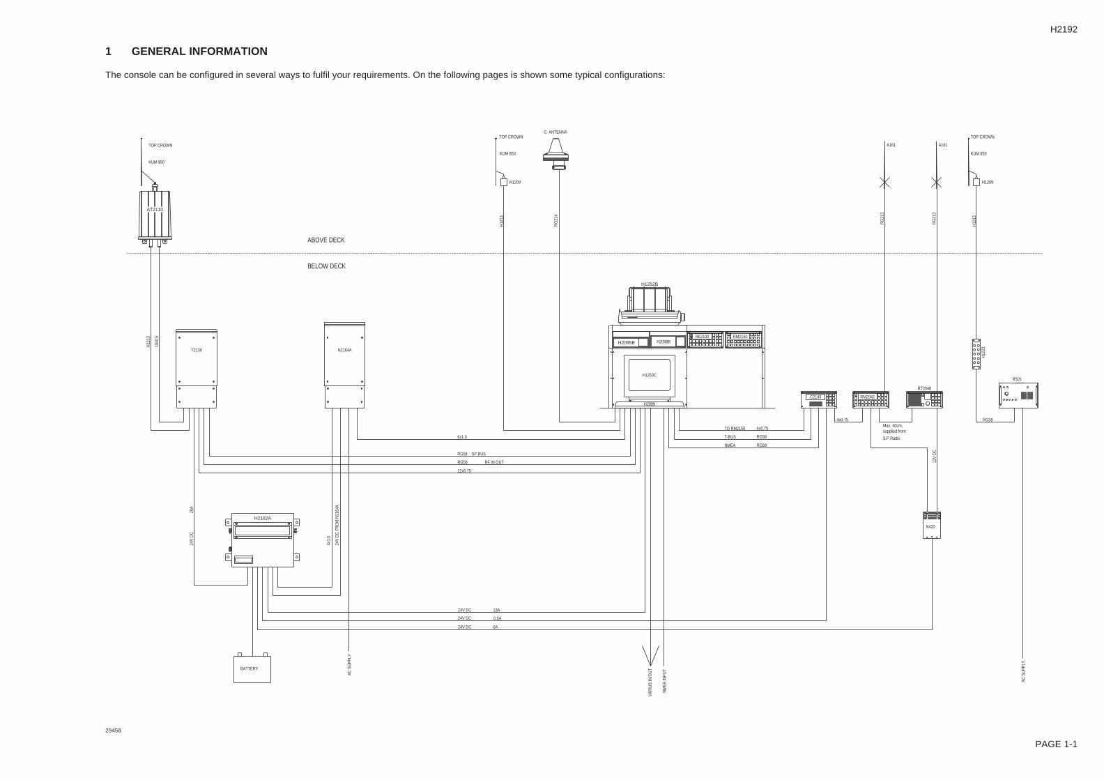
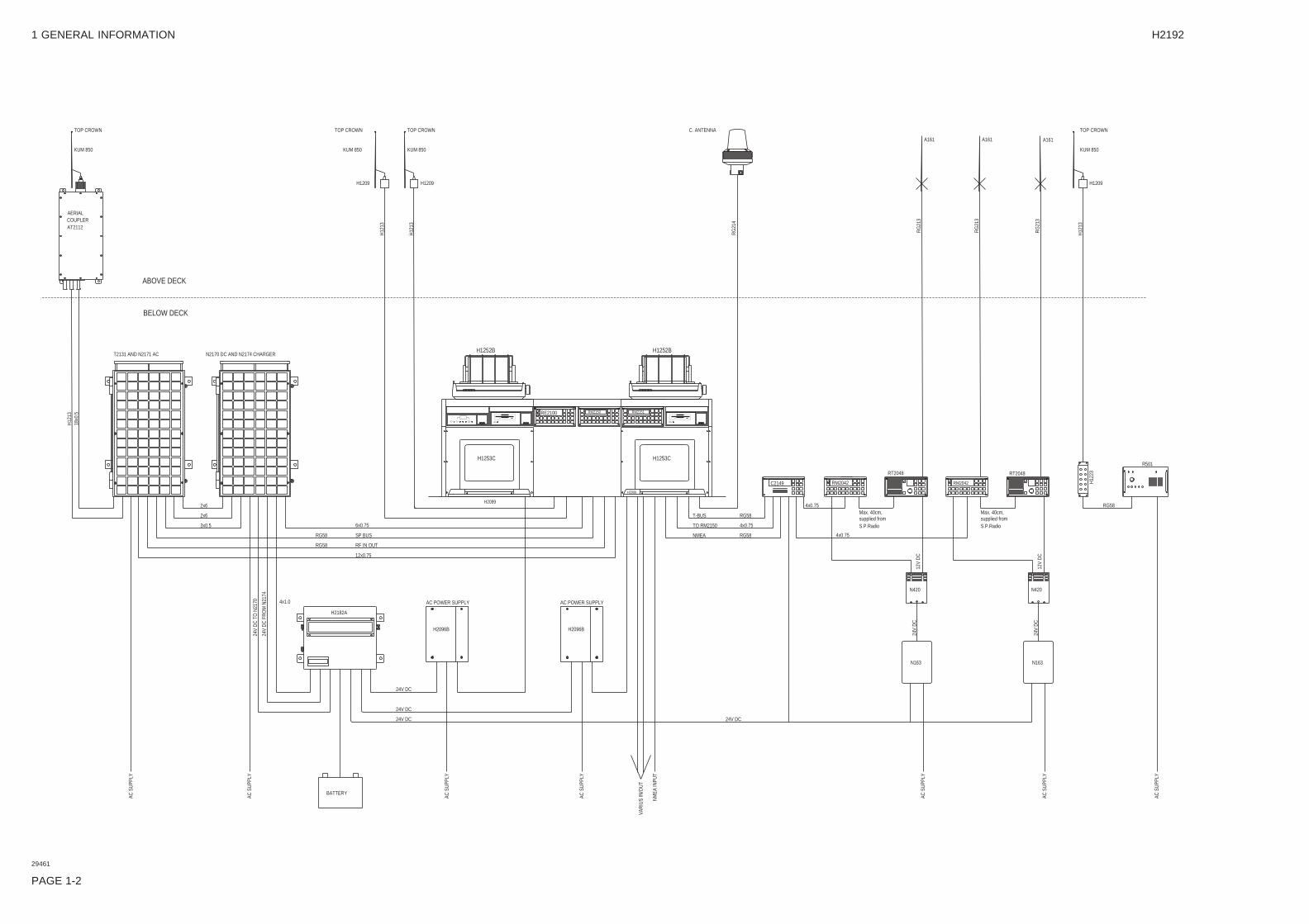
1 GENERAL INFORMATION
The console can be configured in several ways to fulfil your requirements. On the following pages is shown some typical configurations:
H2182A
AT2110
T2130
RM2150
H1252B
H2099
H1253C
H2098BH2095BRE2100
C2149 RM2042
RT2048
N2164A
BATTERY
24V
DC
20A
6A24V DC
AC S
UPP
LY
24V
DC
FR
OM
N21
64A
4x1.
0
24V DC
24V DC
13A
0.5A
12x0.75
RG58 SP BUS
RG58 RF IN OUT
H12
13
10x0
.5
KUM 850
TOP CROWN
BELOW DECK
ABOVE DECK
H12
13
RG
214
KUM 850
TOP CROWN
H1209
C. ANTENNA
S.P.Radio
supplied fromMax. 40cm,
VAR
IUS
IN/O
UT
NM
EA IN
PUT
TO RM2150
NMEA
T-BUS
RG58
4x0.75
RG58
4x0.75
AC S
UPP
LY
N420
12V
DC
RG58
A161
RG
213
R501
H12
23
RG
213
H12
13
KUM 850
TOP CROWN
A161
H1209
6x1.0
PAGE 1-1
29458
1 GENERAL INFORMATION H2192
PAGE 1-2
2x6
24V
DC
TO
N21
70
AC S
UPP
LY
AC S
UPP
LY
2x6
3x0.5
BATTERY
AC S
UPP
LY
AC S
UPP
LY
AC POWER SUPPLY
24V
DC
FR
OM
N21
74
24V DC
24V DC
24V DC
H2182A
4x1.0
RG58
RG58
SP BUS
RF IN OUT
12x0.75
6x0.75
AC POWER SUPPLY
N2170 DC AND N2174 CHARGER
18x0
.5H
1213
T2131 AND N2171 AC
ABOVE DECK
BELOW DECK
TOP CROWN
KUM 850
AERIALCOUPLERAT2112
H1253C
H2099
RE2100 RM2150
H1252B
H1209
TOP CROWN
KUM 850
H12
13
H12
13
H1209
KUM 850
TOP CROWN
RG58 4x0.75
VAR
IUS
IN/O
UT
NM
EA IN
PUT
AC S
UPP
LY
24V DC
NMEA
T-BUS
TO RM2150
RG58
RG58
4x0.75
24V
DC
N163
Max. 40cm, supplied fromS.P.Radio
4x0.75
12V
DC
N420
AC S
UPP
LY
AC S
UPP
LY
24V
DC
N163
12V
DC
N420
supplied fromS.P.Radio
Max. 40cm,
RM2042
H1253C
H2099
RM2151..
C2149
H1252B
RM2042
RT2048
RG
214
C. ANTENNA
RG
213
A161
R501
RT2048
H12
23
RG
213
RG
213
A161 A161
H12
13
KUM 850
H1209
TOP CROWN
H2096BH2096B
29461
1 GENERAL INFORMATION H2192
29465
PAGE 1-3
H2182A
H2096B H2096B N163S
OFF
ON
FUSE
N163S
OFF
ON
FUSE
N163S
OFF
ON
FUSE
C2149 RM2042
RT2048
RM2042
RT2048
H2099
H1253C
H2099
H1253C
H2099
H1253C
H1252B H1252B H1252B
H2095B H2098B H2098B H2098BRM2151RM2151
H2074
RM2150RE2100
RE2100
AC S
UPP
LY22
0V A
C 8
A
2x2.5
24V DC
AC S
UPP
LY
BATTERY
24V
DC
AC S
UPP
LY
AC S
UPP
LY
24V DC 50A
24V
DC
24V
DC
50A
50A
4x1,
0
RG58
RG58
12x0.75
SP BUS
RF IN/OUT
2x2.5
24V DC
24V DC
24V DC
24V
AC
8A
SP SUPPLY 10m
SP SUPPLY 10m
SP SUPPLY 10m
SP SUPPLY 10m
2x0.75 FOR H2074
21x0.5 FOR RE2100
21x0.5 FOR RM2151
RG 58 RF IN OUT
6x0.75
RG 58 SP BUS
T2131 AND N2171 AC N2170
2x6
3x0.5
2x6
BELOW DECK
ABOVE DECK
18x0
.5H
1213
COUPLERAT2112
AERIAL
TOP CROWN
KUM 850
T2131 AND N2171 AC N2170 AND N2174
2x6
3x0.5
2x6
H12
1318
x0.5
NOTE 2
FOR
RM
2151
FOR
RM
2151
FOR
RM
2150
FOR
SAT
-C
TOP CROWN
KUM 850
H1209
COUPLERAT2112
AERIAL
TOP CROWN
KUM 850
H12
13
KUM 850
TOP CROWN
H1209
C. ANTENNA
H12
13
H12
13
RG
214
KUM 850
TOP CROWN
H1209
NM
EA IN
PUT
AC S
UPP
LY
NM
EA F
RO
M G
PS
AC S
UPP
LY
TO RM2150
24V
AC
6A
24V DC
24V
AC
4A
NMEA
24V
DC
0.5
AR
G 5
8
24V
DC
6A
220V
AC
1A
24V
DC
6A
4x0.75
RG58
12V
DC
12V
DC
N420
12V
DC
AC S
UPP
LY
AC S
UPP
LY
220V
AC
1A
24V
DC
6A
24V
DC
6A
12V
DC
N420
Max. 40cm,
S.P.Radiosupplied from
A161
T-BUS
NOTE 1
Max. 40cm, supplied fromS.P.Radio
RG58 4x0.5
4x0.5
RG
213
RG
213
A161
R501
RG58
H12
23
RG
213
A161
H12
13
H1209
TOP CROWN
KUM 850
AC POWER SUPPLY AC POWER SUPPLYH2183A
220V
AC
8AAC
SU
PPLY
24V
DC
50A
1 GENERAL INFORMATION H2192
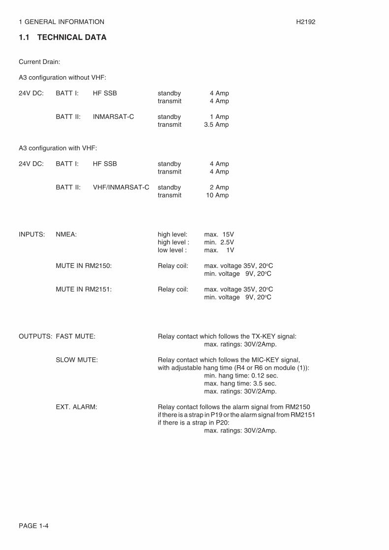
1.1 TECHNICAL DATA
Current Drain:
A3 configuration without VHF:
24V DC: BATT I: HF SSB standby 4 Amptransmit 4 Amp
BATT II: INMARSAT-C standby 1 Amptransmit 3.5 Amp
A3 configuration with VHF:
24V DC: BATT I: HF SSB standby 4 Amptransmit 4 Amp
BATT II: VHF/INMARSAT-C standby 2 Amptransmit 10 Amp
INPUTS: NMEA: high level: max. 15Vhigh level : min. 2.5Vlow level : max. 1V
MUTE IN RM2150: Relay coil: max. voltage 35V, 20oCmin. voltage 9V, 20oC
MUTE IN RM2151: Relay coil: max. voltage 35V, 20oCmin. voltage 9V, 20oC
OUTPUTS: FAST MUTE: Relay contact which follows the TX-KEY signal:max. ratings: 30V/2Amp.
SLOW MUTE: Relay contact which follows the MIC-KEY signal,with adjustable hang time (R4 or R6 on module (1)):
min. hang time: 0.12 sec.max. hang time: 3.5 sec.max. ratings: 30V/2Amp.
EXT. ALARM: Relay contact follows the alarm signal from RM2150if there is a strap in P19 or the alarm signal from RM2151if there is a strap in P20:
max. ratings: 30V/2Amp.
PAGE 1-4
PAGE 2-1
H2192
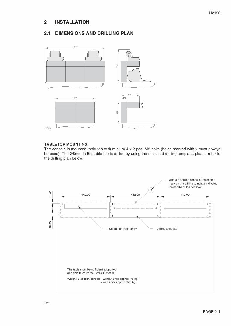
2 INSTALLATION
2.1 DIMENSIONS AND DRILLING PLAN
1365
920 136
425
136
490
740
27666
TABLETOP MOUNTINGThe console is mounted table top with minium 4 x 2 pcs. M8 bolts (holes marked with x must alwaysbe used). The Ø8mm in the table top is drilled by using the enclosed drilling template, please refer tothe drilling plan below.
Drilling template
The table must be sufficient supportedand able to carry the GMDSS-station.
Weight: 3 section console - without units approx. 75 kg. - with units approx. 125 kg.
28.5
011
.00
442.00 442.00 442.00
mark on the drilling template indicatesthe middle of the console.
27664
Cutout for cable entry
With a 3 section console, the center
X
X X
X
X
X
X
X

2 INSTALLATION H2192
PAGE 2-2
BULKHEAD MOUNTINGThe console is mounted on the bulkhead with M8 bolts in the appropriate holes in the base mountingplates. Please refer to the drilling plan below.
185m
m18
5mm
45m
m
430.
00
30mm442mm 442mm
Steel bulkhead
Lining
Steel bracket, min. 6mm thick,welded to steel bulkhead.4 pcs. for 3-section station/3 pcs. for 2-section station.
3 holes drilled and tappedfor M8 bolts.
55m
m
approx. 400mm Cutout for cable entry
442mm
100mm
40m
m
15m
m30
mm
cobber
4 pcs. M6 bolts
Earth stubs, made of steel andwelded to the steel bulkhead.
111mm
15m
m
100mmx0.5mm
27665
TOP VIEW
FRONT VIEW
2 INSTALLATION H2192
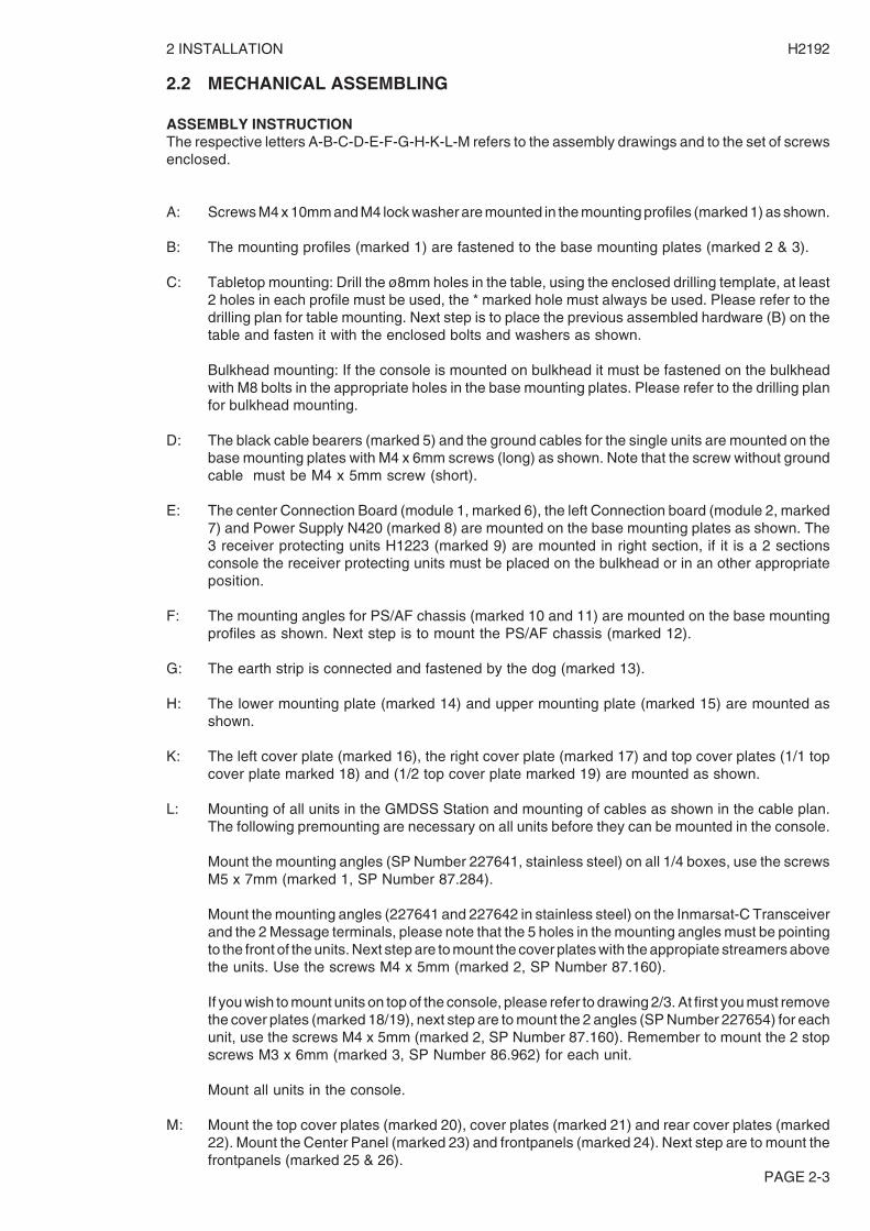
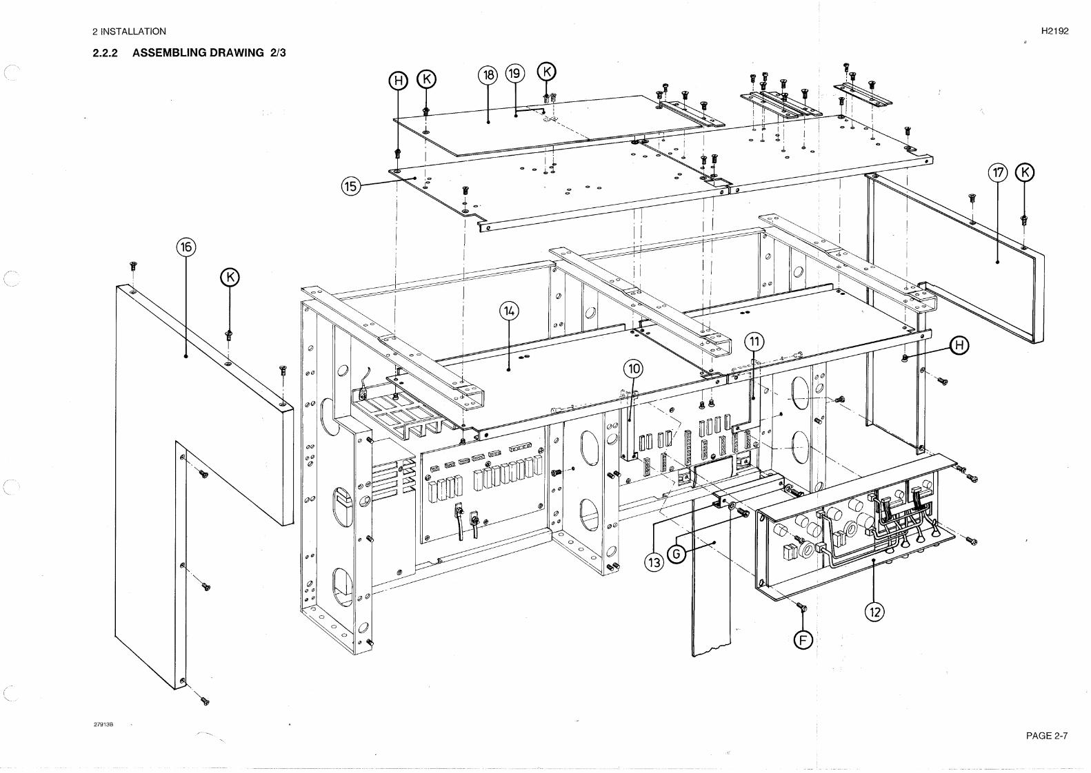
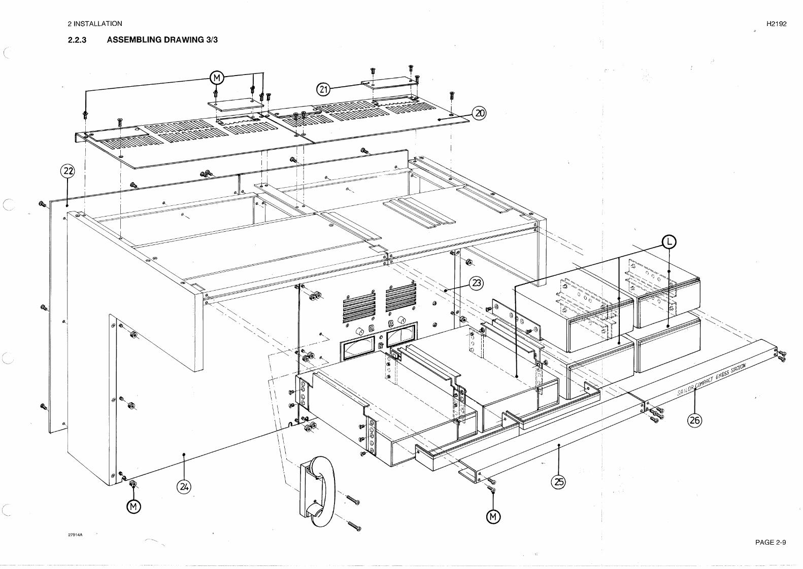
2.2 MECHANICAL ASSEMBLING
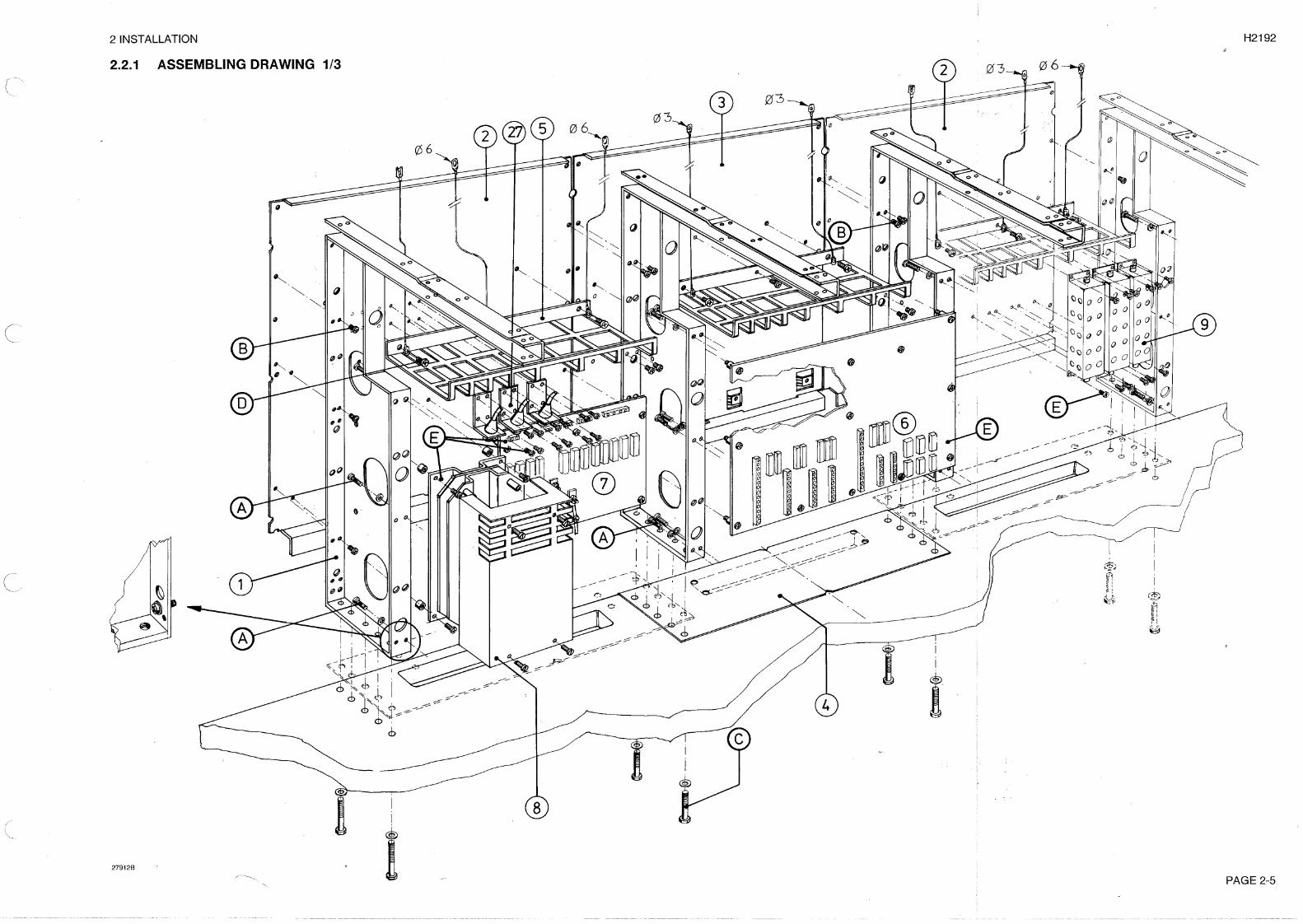
ASSEMBLY INSTRUCTIONThe respective letters A-B-C-D-E-F-G-H-K-L-M refers to the assembly drawings and to the set of screwsenclosed.
A: Screws M4 x 10mm and M4 lock washer are mounted in the mounting profiles (marked 1) as shown.
B: The mounting profiles (marked 1) are fastened to the base mounting plates (marked 2 & 3).
C: Tabletop mounting: Drill the ø8mm holes in the table, using the enclosed drilling template, at least2 holes in each profile must be used, the * marked hole must always be used. Please refer to thedrilling plan for table mounting. Next step is to place the previous assembled hardware (B) on thetable and fasten it with the enclosed bolts and washers as shown.
Bulkhead mounting: If the console is mounted on bulkhead it must be fastened on the bulkheadwith M8 bolts in the appropriate holes in the base mounting plates. Please refer to the drilling planfor bulkhead mounting.
D: The black cable bearers (marked 5) and the ground cables for the single units are mounted on thebase mounting plates with M4 x 6mm screws (long) as shown. Note that the screw without groundcable must be M4 x 5mm screw (short).
E: The center Connection Board (module 1, marked 6), the left Connection board (module 2, marked7) and Power Supply N420 (marked 8) are mounted on the base mounting plates as shown. The3 receiver protecting units H1223 (marked 9) are mounted in right section, if it is a 2 sectionsconsole the receiver protecting units must be placed on the bulkhead or in an other appropriateposition.
F: The mounting angles for PS/AF chassis (marked 10 and 11) are mounted on the base mountingprofiles as shown. Next step is to mount the PS/AF chassis (marked 12).
G: The earth strip is connected and fastened by the dog (marked 13).
H: The lower mounting plate (marked 14) and upper mounting plate (marked 15) are mounted asshown.
K: The left cover plate (marked 16), the right cover plate (marked 17) and top cover plates (1/1 topcover plate marked 18) and (1/2 top cover plate marked 19) are mounted as shown.
L: Mounting of all units in the GMDSS Station and mounting of cables as shown in the cable plan.The following premounting are necessary on all units before they can be mounted in the console.
Mount the mounting angles (SP Number 227641, stainless steel) on all 1/4 boxes, use the screwsM5 x 7mm (marked 1, SP Number 87.284).
Mount the mounting angles (227641 and 227642 in stainless steel) on the Inmarsat-C Transceiverand the 2 Message terminals, please note that the 5 holes in the mounting angles must be pointingto the front of the units. Next step are to mount the cover plates with the appropiate streamers abovethe units. Use the screws M4 x 5mm (marked 2, SP Number 87.160).
If you wish to mount units on top of the console, please refer to drawing 2/3. At first you must removethe cover plates (marked 18/19), next step are to mount the 2 angles (SP Number 227654) for eachunit, use the screws M4 x 5mm (marked 2, SP Number 87.160). Remember to mount the 2 stopscrews M3 x 6mm (marked 3, SP Number 86.962) for each unit.
Mount all units in the console.
M: Mount the top cover plates (marked 20), cover plates (marked 21) and rear cover plates (marked22). Mount the Center Panel (marked 23) and frontpanels (marked 24). Next step are to mount thefrontpanels (marked 25 & 26).
PAGE 2-3

2 INSTALLATION H2192
PAGE 2-4
2 INSTALLATION H2192
PAGE 2-11
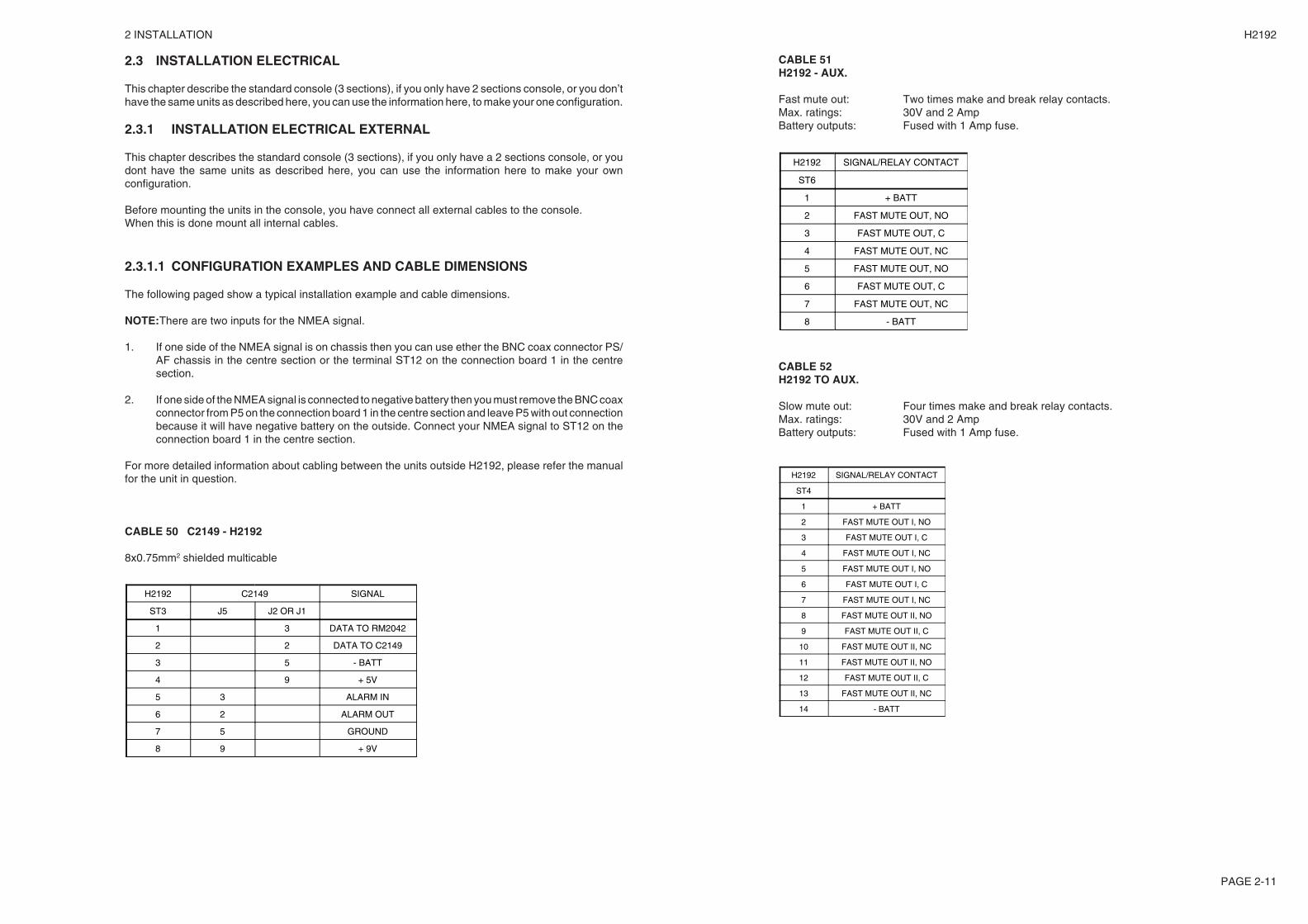
CABLE 51H2192 - AUX.
Fast mute out: Two times make and break relay contacts.Max. ratings: 30V and 2 AmpBattery outputs: Fused with 1 Amp fuse.
H2192 SIGNAL/RELAY CONTACT
ST6
1 + BATT
2 FAST MUTE OUT, NO
3 FAST MUTE OUT, C
4 FAST MUTE OUT, NC
5 FAST MUTE OUT, NO
6 FAST MUTE OUT, C
7 FAST MUTE OUT, NC
8 - BATT
CABLE 52H2192 TO AUX.
Slow mute out: Four times make and break relay contacts.Max. ratings: 30V and 2 AmpBattery outputs: Fused with 1 Amp fuse.
H2192 SIGNAL/RELAY CONTACT
ST4
1 + BATT
2 FAST MUTE OUT I, NO
3 FAST MUTE OUT I, C
4 FAST MUTE OUT I, NC
5 FAST MUTE OUT I, NO
6 FAST MUTE OUT I, C
7 FAST MUTE OUT I, NC
8 FAST MUTE OUT II, NO
9 FAST MUTE OUT II, C
10 FAST MUTE OUT II, NC
11 FAST MUTE OUT II, NO
12 FAST MUTE OUT II, C
13 FAST MUTE OUT II, NC
14 - BATT
2.3 INSTALLATION ELECTRICAL
This chapter describe the standard console (3 sections), if you only have 2 sections console, or you don’thave the same units as described here, you can use the information here, to make your one configuration.
2.3.1 INSTALLATION ELECTRICAL EXTERNAL
This chapter describes the standard console (3 sections), if you only have a 2 sections console, or youdont have the same units as described here, you can use the information here to make your ownconfiguration.
Before mounting the units in the console, you have connect all external cables to the console.When this is done mount all internal cables.
2.3.1.1 CONFIGURATION EXAMPLES AND CABLE DIMENSIONS
The following paged show a typical installation example and cable dimensions.
NOTE:There are two inputs for the NMEA signal.
1. If one side of the NMEA signal is on chassis then you can use ether the BNC coax connector PS/AF chassis in the centre section or the terminal ST12 on the connection board 1 in the centresection.
2. If one side of the NMEA signal is connected to negative battery then you must remove the BNC coaxconnector from P5 on the connection board 1 in the centre section and leave P5 with out connectionbecause it will have negative battery on the outside. Connect your NMEA signal to ST12 on theconnection board 1 in the centre section.
For more detailed information about cabling between the units outside H2192, please refer the manualfor the unit in question.
CABLE 50 C2149 - H2192
8x0.75mm2 shielded multicable
H2192 C2149 SIGNAL
ST3 J5 J2 OR J1
1 3 DATA TO RM2042
2 2 DATA TO C2149
3 5 - BATT
4 9 + 5V
5 3 ALARM IN
6 2 ALARM OUT
7 5 GROUND
8 9 + 9V
2 INSTALLATION H2192
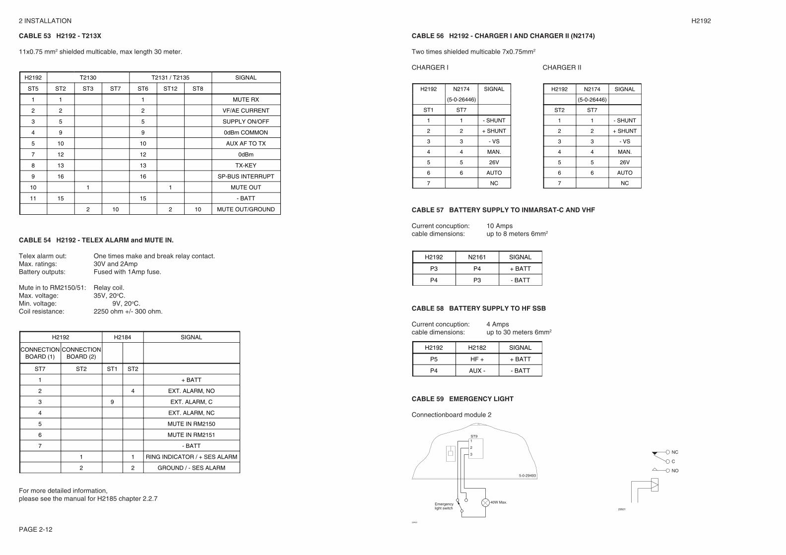
CABLE 53 H2192 - T213X
11x0.75 mm2 shielded multicable, max length 30 meter.
H2192 T2130 T2131 / T2135 SIGNAL
ST5 ST2 ST3 ST7 ST6 ST12 ST8
1 1 1 MUTE RX
2 2 2 VF/AE CURRENT
3 5 5 SUPPLY ON/OFF
4 9 9 0dBm COMMON
5 10 10 AUX AF TO TX
7 12 12 0dBm
8 13 13 TX-KEY
9 16 16 SP-BUS INTERRUPT
10 1 1 MUTE OUT
11 15 15 - BATT
2 10 2 10 MUTE OUT/GROUND
CABLE 54 H2192 - TELEX ALARM and MUTE IN.
Telex alarm out: One times make and break relay contact.Max. ratings: 30V and 2AmpBattery outputs: Fused with 1Amp fuse.
Mute in to RM2150/51: Relay coil.Max. voltage: 35V, 20oC.Min. voltage: 9V, 20oC.Coil resistance: 2250 ohm +/- 300 ohm.
H2192 H2184 SIGNAL
CONNECTIONBOARD (1)
CONNECTIONBOARD (2)
ST7 ST2 ST1 ST2
1 + BATT
2 4 EXT. ALARM, NO
3 9 EXT. ALARM, C
4 EXT. ALARM, NC
5 MUTE IN RM2150
6 MUTE IN RM2151
7 - BATT
1 1 RING INDICATOR / + SES ALARM
2 2 GROUND / - SES ALARM
For more detailed information,please see the manual for H2185 chapter 2.2.7
CABLE 56 H2192 - CHARGER I AND CHARGER II (N2174)
Two times shielded multicable 7x0.75mm2
CHARGER I CHARGER II
H2192 N2174 SIGNAL
(5-0-26446)
ST1 ST7
1 1 - SHUNT
2 2 + SHUNT
3 3 - VS
4 4 MAN.
5 5 26V
6 6 AUTO
7 NC
H2192 N2174 SIGNAL
(5-0-26446)
ST2 ST7
1 1 - SHUNT
2 2 + SHUNT
3 3 - VS
4 4 MAN.
5 5 26V
6 6 AUTO
7 NC
CABLE 57 BATTERY SUPPLY TO INMARSAT-C AND VHF
Current concuption: 10 Ampscable dimensions: up to 8 meters 6mm2
H2192 N2161 SIGNAL
P3 P4 + BATT
P4 P3 - BATT
CABLE 58 BATTERY SUPPLY TO HF SSB
Current concuption: 4 Ampscable dimensions: up to 30 meters 6mm2
H2192 H2182 SIGNAL
P5 HF + + BATT
P4 AUX - - BATT
CABLE 59 EMERGENCY LIGHT
Connectionboard module 2
29493
Emergencylight switch
40W Max.
5-0-29493
2
ST9
3
1
NO
C
NC
29501
PAGE 2-12
2 INSTALLATION H2192
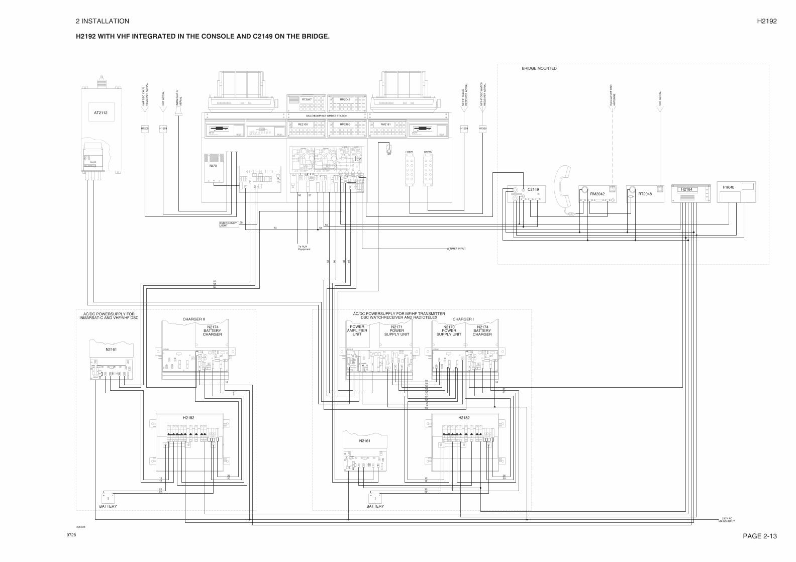
H2192 WITH VHF INTEGRATED IN THE CONSOLE AND C2149 ON THE BRIDGE.
P3
P2
P1P1
P2
P3
P1
P2P2
P1
Power supply Power supply AF-Amplifier AF-Amplifier
COMPACT GMDSS STATION
- + - +
SAILOR
- + +-
CHARGER II
ST6
ST2
ST
3S
T7
ST4
ST1
P5 P6
P8P7
H2182
2222
1212
AC/DC POWERSUPPLY FORINMARSAT-C AND VHF/VHF DSC
TX+
N2174+-
TX-
N2174
5-0-26446
2026
HF+
LIGHT+
VHF+ +
AUX VS+-
AUX-+
VS-
SHUNT
18
2121
CHARGER BATTERY
N2174
N420
PowerOn/Off
H2098A Message Terminal Inmarsat-C Transceiver
to send alarm.
Press both keysfor 5 seconds
AlarmAlarmMailSendLoginSetPowerOn/Off
H2095B
RE2100
PowerOn/Off
H2098A Message Terminal
RM2150 RM2151
H1223
H1209
P11P13
P14P12
ST9
ST10
ST
5ST1ST3
ST
11
ST
6
P9
P10
N2174BATTERY
N2170POWERPOWERN2171
-+
+ ---- + ++++++ -VS SHUNTVSTX TX N2174 N2174 VHF LIGHT AUXAUXHF
AT2112
BATTERY
CHARGER SUPPLY UNITAMPLIFIER
212112
9
18
220V ACMAINS INPUT.
19
2026
2222
1212
H2182
5-0-264465-0-26413
POWERSUPPLY UNIT
ST6
ST2
ST
3S
T7
ST4
ST1
P5 P6
P8P7
12
10101010
2
UNIT
12
12
I
DSC WATCHRECEIVER AND RADIOTELEXAC/DC POWERSUPPLY FOR MF/HF TRANSMITTER
CHARGER I
H1223
H1209
EMERGENCYLIGHT
RE
CE
IVE
R A
ER
IAL
MF
/HF
DS
C W
AT
CH
RE
CE
IVE
R A
ER
IAL
MF
/HF
TE
LEX
H1209
VH
F D
SC
CH
70
RE
CE
IVE
R A
ER
IAL
H1209
VH
F A
ER
IAL
INM
AR
SA
T-C
AE
RIA
L
RM2042 RT2048C2149
AN
TE
NN
EO
ptio
nel V
HF
DS
C
VH
F A
ER
IAL
H1604BH2184
NMEA INPUT
29500B
RM2042RT2047
BATTERY
+ -I
To AUXEquipment
52 51
5450
59
5757
53 56 58 58N2161
56
54
BRIDGE MOUNTED
N2161
PAGE 2-139728

2 INSTALLATION H2192
PAGE 2-14
2.3.2 INSTALLATION ELECTRICAL INTERNAL
Before you mount a cable in the console, you must put a number label on the cable in accordance withtable 1.Start with mounting cable no. 1.If you haven’t got a Inmarsat-C in the console, you don’t neat cable no. 5, 6, 7, 8, 11, 12, 36, 37.If you haven’t got a VHF mounted in the console, you don’t neat to mount cable no. 9, 10, 18, 35, 39, 41.
NOTE 1: The T-bus on Inmarsat-C has to be connected to:
1. Cable 13 if you have a C2149 in your configuration.2. Cable 38 if you haven’t a C2149 in your configuration.3. Cable 13 if you have a remote alarm unit with EGC printer (H1604B) in your configuration.
The NMEA input on RM2042 has to be connected to:
1. Noting if you have a C2149 in your configuration.2. Cable 39 if you haven’t a C2149 in your configuration.
NOTE 2: There are two inputs for the NMEA signal.
1. If one side of the NMEA signal is on chassis then you can use ether the BNC coax connector PS/AF chassis in the centre section or the terminal ST12 on the connection board 1 in thecentre section.
2. If one side of the NMEA signal is connected to negative battery then you must remove theBNC coax connector from P5 on the connection board 1 in the centre section and leave P5with out connection because it will have negative battery on the outside. Connect your NMEAsignal to ST12 on the connection board 1 in the centre section.
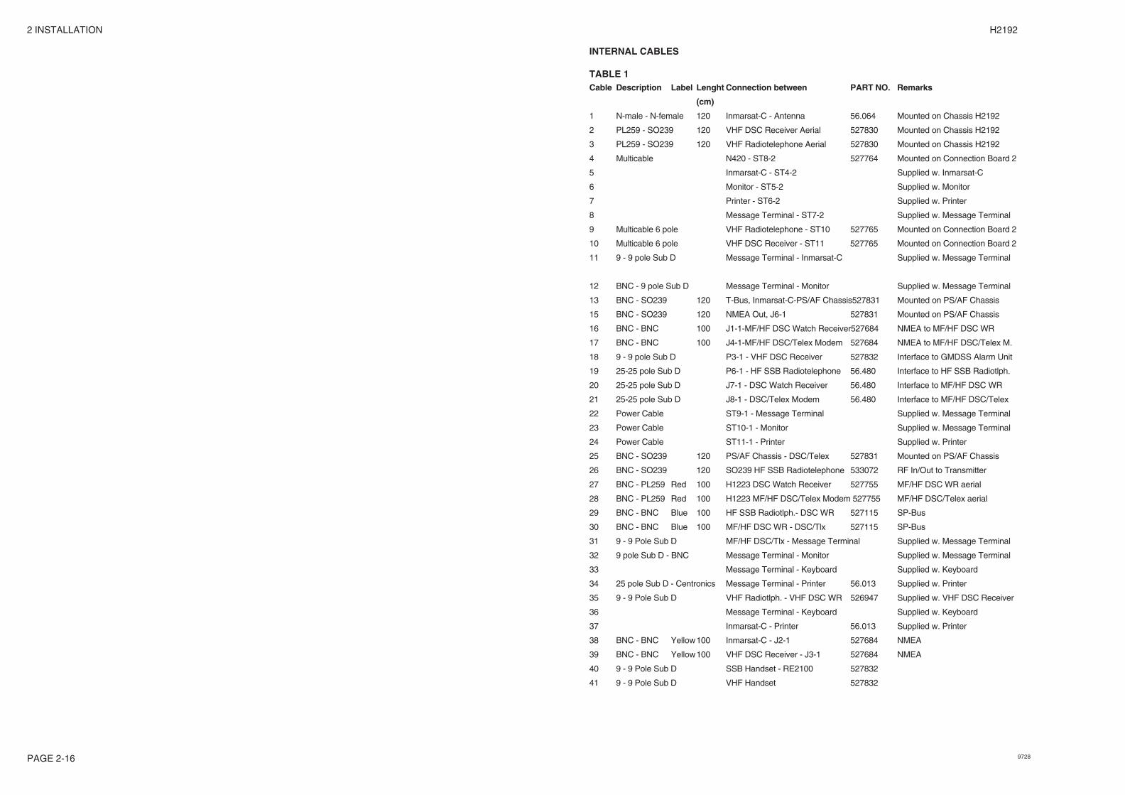
INTERNAL CABLES
TABLE 1Cable Description Label Lenght Connection between PART NO. Remarks
(cm)
1 N-male - N-female 120 Inmarsat-C - Antenna 56.064 Mounted on Chassis H2192
2 PL259 - SO239 120 VHF DSC Receiver Aerial 527830 Mounted on Chassis H2192
3 PL259 - SO239 120 VHF Radiotelephone Aerial 527830 Mounted on Chassis H2192
4 Multicable N420 - ST8-2 527764 Mounted on Connection Board 2
5 Inmarsat-C - ST4-2 Supplied w. Inmarsat-C
6 Monitor - ST5-2 Supplied w. Monitor
7 Printer - ST6-2 Supplied w. Printer
8 Message Terminal - ST7-2 Supplied w. Message Terminal
9 Multicable 6 pole VHF Radiotelephone - ST10 527765 Mounted on Connection Board 2
10 Multicable 6 pole VHF DSC Receiver - ST11 527765 Mounted on Connection Board 2
11 9 - 9 pole Sub D Message Terminal - Inmarsat-C Supplied w. Message Terminal
12 BNC - 9 pole Sub D Message Terminal - Monitor Supplied w. Message Terminal
13 BNC - SO239 120 T-Bus, Inmarsat-C-PS/AF Chassis527831 Mounted on PS/AF Chassis
15 BNC - SO239 120 NMEA Out, J6-1 527831 Mounted on PS/AF Chassis
16 BNC - BNC 100 J1-1-MF/HF DSC Watch Receiver527684 NMEA to MF/HF DSC WR
17 BNC - BNC 100 J4-1-MF/HF DSC/Telex Modem 527684 NMEA to MF/HF DSC/Telex M.
18 9 - 9 pole Sub D P3-1 - VHF DSC Receiver 527832 Interface to GMDSS Alarm Unit
19 25-25 pole Sub D P6-1 - HF SSB Radiotelephone 56.480 Interface to HF SSB Radiotlph.
20 25-25 pole Sub D J7-1 - DSC Watch Receiver 56.480 Interface to MF/HF DSC WR
21 25-25 pole Sub D J8-1 - DSC/Telex Modem 56.480 Interface to MF/HF DSC/Telex
22 Power Cable ST9-1 - Message Terminal Supplied w. Message Terminal
23 Power Cable ST10-1 - Monitor Supplied w. Message Terminal
24 Power Cable ST11-1 - Printer Supplied w. Printer
25 BNC - SO239 120 PS/AF Chassis - DSC/Telex 527831 Mounted on PS/AF Chassis
26 BNC - SO239 120 SO239 HF SSB Radiotelephone 533072 RF In/Out to Transmitter
27 BNC - PL259 Red 100 H1223 DSC Watch Receiver 527755 MF/HF DSC WR aerial
28 BNC - PL259 Red 100 H1223 MF/HF DSC/Telex Modem 527755 MF/HF DSC/Telex aerial
29 BNC - BNC Blue 100 HF SSB Radiotlph.- DSC WR 527115 SP-Bus
30 BNC - BNC Blue 100 MF/HF DSC WR - DSC/Tlx 527115 SP-Bus
31 9 - 9 Pole Sub D MF/HF DSC/Tlx - Message Terminal Supplied w. Message Terminal
32 9 pole Sub D - BNC Message Terminal - Monitor Supplied w. Message Terminal
33 Message Terminal - Keyboard Supplied w. Keyboard
34 25 pole Sub D - Centronics Message Terminal - Printer 56.013 Supplied w. Printer
35 9 - 9 Pole Sub D VHF Radiotlph. - VHF DSC WR 526947 Supplied w. VHF DSC Receiver
36 Message Terminal - Keyboard Supplied w. Keyboard
37 Inmarsat-C - Printer 56.013 Supplied w. Printer
38 BNC - BNC Yellow100 Inmarsat-C - J2-1 527684 NMEA
39 BNC - BNC Yellow100 VHF DSC Receiver - J3-1 527684 NMEA
40 9 - 9 Pole Sub D SSB Handset - RE2100 527832
41 9 - 9 Pole Sub D VHF Handset 527832
9728

2 INSTALLATION H2192
INTERNAL CABLE OVERVIEW WITHOUT GMDSS ALARM UNIT C2149
S N N
RM2042 RM2048
RE2100 RM2150 RM2151H2095B H2098A
H1253B
H2099
H12
23
H12
23
H2099 SSB HANDSET VHF HANDSET
H1252B
N420
ConnectionBoard (1)
ConnectionBoard (2)
VHF DSC Aerial (RM2042)VHF Aerial (RT2048)Inmarsat-C Aerial
MF/HF DSC AerialMF/HF DSC Telex modem
Aerial
2827
26
33
34
3029
35
12
11 38 37
36
4
5 6 87 9 10
1 2 3
15
16 17 18 19 20 2123
2224
25
TMMPB
U B E EAAUS
I OSN U
T
H1253B
H1252B
36
38
37
39
39
H2098A
NC13
13
16
17
18
19
20
21 22
23
31
33
1
3
2
5
6
7
8
910
2827
26
25
31
32
32
11
3424
27906D
41
40
PAGE 2-159728
2 INSTALLATION H2192
INTERNAL CABLES
TABLE 1Cable Description Label Lenght Connection between PART NO. Remarks
(cm)
1 N-male - N-female 120 Inmarsat-C - Antenna 56.064 Mounted on Chassis H2192
2 PL259 - SO239 120 VHF DSC Receiver Aerial 527830 Mounted on Chassis H2192
3 PL259 - SO239 120 VHF Radiotelephone Aerial 527830 Mounted on Chassis H2192
4 Multicable N420 - ST8-2 527764 Mounted on Connection Board 2
5 Inmarsat-C - ST4-2 Supplied w. Inmarsat-C
6 Monitor - ST5-2 Supplied w. Monitor
7 Printer - ST6-2 Supplied w. Printer
8 Message Terminal - ST7-2 Supplied w. Message Terminal
9 Multicable 6 pole VHF Radiotelephone - ST10 527765 Mounted on Connection Board 2
10 Multicable 6 pole VHF DSC Receiver - ST11 527765 Mounted on Connection Board 2
11 9 - 9 pole Sub D Message Terminal - Inmarsat-C Supplied w. Message Terminal
12 BNC - 9 pole Sub D Message Terminal - Monitor Supplied w. Message Terminal
13 BNC - SO239 120 T-Bus, Inmarsat-C-PS/AF Chassis527831 Mounted on PS/AF Chassis
15 BNC - SO239 120 NMEA Out, J6-1 527831 Mounted on PS/AF Chassis
16 BNC - BNC 100 J1-1-MF/HF DSC Watch Receiver527684 NMEA to MF/HF DSC WR
17 BNC - BNC 100 J4-1-MF/HF DSC/Telex Modem 527684 NMEA to MF/HF DSC/Telex M.
18 9 - 9 pole Sub D P3-1 - VHF DSC Receiver 527832 Interface to GMDSS Alarm Unit
19 25-25 pole Sub D P6-1 - HF SSB Radiotelephone 56.480 Interface to HF SSB Radiotlph.
20 25-25 pole Sub D J7-1 - DSC Watch Receiver 56.480 Interface to MF/HF DSC WR
21 25-25 pole Sub D J8-1 - DSC/Telex Modem 56.480 Interface to MF/HF DSC/Telex
22 Power Cable ST9-1 - Message Terminal Supplied w. Message Terminal
23 Power Cable ST10-1 - Monitor Supplied w. Message Terminal
24 Power Cable ST11-1 - Printer Supplied w. Printer
25 BNC - SO239 120 PS/AF Chassis - DSC/Telex 527831 Mounted on PS/AF Chassis
26 BNC - SO239 120 SO239 HF SSB Radiotelephone 533072 RF In/Out to Transmitter
27 BNC - PL259 Red 100 H1223 DSC Watch Receiver 527755 MF/HF DSC WR aerial
28 BNC - PL259 Red 100 H1223 MF/HF DSC/Telex Modem 527755 MF/HF DSC/Telex aerial
29 BNC - BNC Blue 100 HF SSB Radiotlph.- DSC WR 527115 SP-Bus
30 BNC - BNC Blue 100 MF/HF DSC WR - DSC/Tlx 527115 SP-Bus
31 9 - 9 Pole Sub D MF/HF DSC/Tlx - Message Terminal Supplied w. Message Terminal
32 9 pole Sub D - BNC Message Terminal - Monitor Supplied w. Message Terminal
33 Message Terminal - Keyboard Supplied w. Keyboard
34 25 pole Sub D - Centronics Message Terminal - Printer 56.013 Supplied w. Printer
35 9 - 9 Pole Sub D VHF Radiotlph. - VHF DSC WR 526947 Supplied w. VHF DSC Receiver
36 Message Terminal - Keyboard Supplied w. Keyboard
37 Inmarsat-C - Printer 56.013 Supplied w. Printer
38 BNC - BNC Yellow100 Inmarsat-C - J2-1 527684 NMEA
39 BNC - BNC Yellow100 VHF DSC Receiver - J3-1 527684 NMEA
40 9 - 9 Pole Sub D SSB Handset - RE2100 527832
41 9 - 9 Pole Sub D VHF Handset 527832
PAGE 2-16 9728

2 INSTALLATION H2192
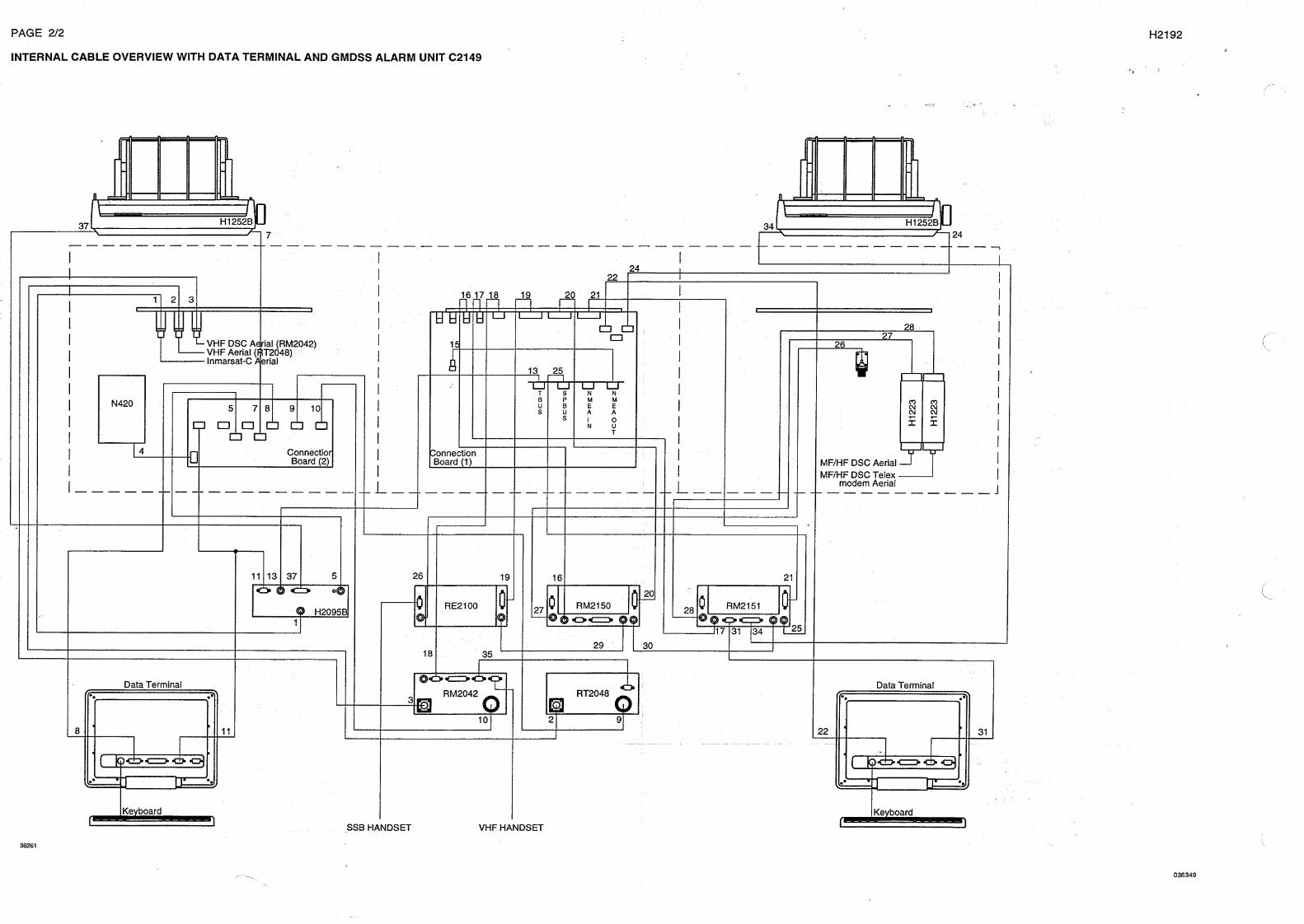
INTERNAL CABLE OVERVIEW WITH GMDSS ALARM UNIT C2149
RM2042 RT2048
RE2100 RM2150 RM2151H2095B
H1253B
H2099
H12
23
H12
23
H2099 SSB HANDSET VHF HANDSET
H1252B
N420
ConnectionBoard (1)
ConnectionBoard (2)
VHF DSC Aerial (RM2042)VHF Aerial (RT2048)Inmarsat-C Aerial
MF/HF DSC AerialMF/HF DSC Telex
modem Aerial
2827
26
33
34
302935
12
11 13 37
36
4
5 6 87 9 10
1 2 3
15
16 17 18 19 20 2123
2224
25
T S N NMMPB
U B E EAAUS
I OSN U
T
H1253B
H1252B
36
37
H2098A
13
16
17
18
19
20
21 22
23
31
33
1
3
2
5
6
7
8
910
2827
26
25
31
32
32
11
3424
H2098A
27907D
PAGE 2-179728

2 INSTALLATION H2192
PAGE 2-18
2.4 MODULE LOCATION
Power supply
P2
Power supply
P1
P2
AF-Amplifier
P3
P1
AF-Amplifier
P1
P2
P3 P1
P2
PU II
module 9Power Supply
Connection boardmodule 1
29497B
N420
module 2Connection board
PU I
module 9Power Supply
H1223
MF
/HF
DS
C
AF-Amp.
module 10Left
AF-Amp.
module 10Right
Tel
ex m
odem
M
F/H
F D
SC
Aer
ial
Aer
ial
H1223
9728
2 INSTALLATION H2192
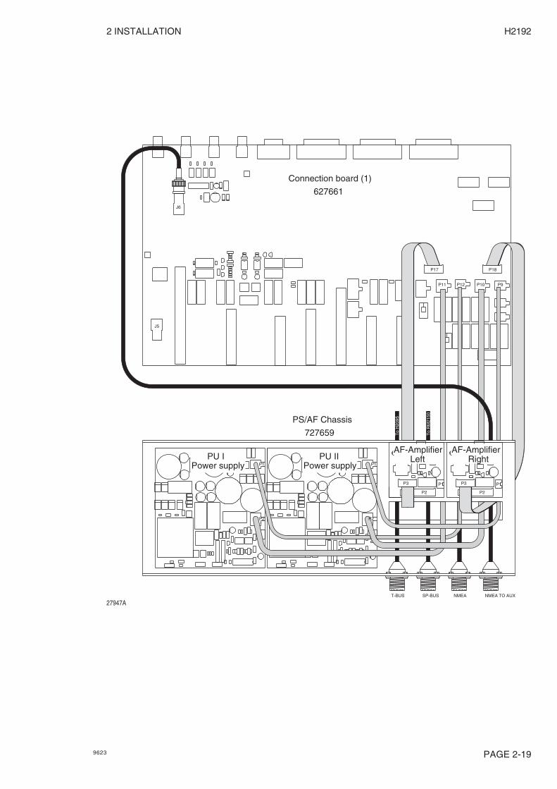
27947A
P3
P2
P1P1
P2
P3
P1
P2P2
P1
P9P10P12P11
P18P17
T-BUS SP-BUS NMEA NMEA TO AUX
J5
J6
Connection board (1)
Power supply Left
627661
727659
PS/AF Chassis
PU IPower supply
PU IIAF-Amplifier
RightAF-Amplifier
To
H20
95
To
RM
2150
PAGE 2-199623

2 INSTALLATION H2192
F13
F21
1 2 7 1 8 2
ST5
ST8
ST2
P3
F12
F11
P4
F2
F1
ST4
F3
F4
ST1 ST3
ST9
F5
F6
F13
F14
ST6
F9
F10
F7
F8
ST7 ST11
P2
TR1
P1
ST10
Connection board (2) 627662
F4
J5
ST4
ST12
J6
J3J2
627661
ST5
F3
F9
F1
F8
F2
F6
F7
F5
ST6
RE3
ST7 ST3
RE2
RE1 RE6RE5
RE4
F10
F11
ST2ST1
P1
P5
F17
P4
F14
F15
F18
F19
F16
P7 P8P11
P17
P2P12
Connection board (1)
J4J1 J7 J8
ST9
F23
F22
P13
P14
F20
F12
P9P10
P18
ST10
ST11
29496A
PAGE 2-20 9623


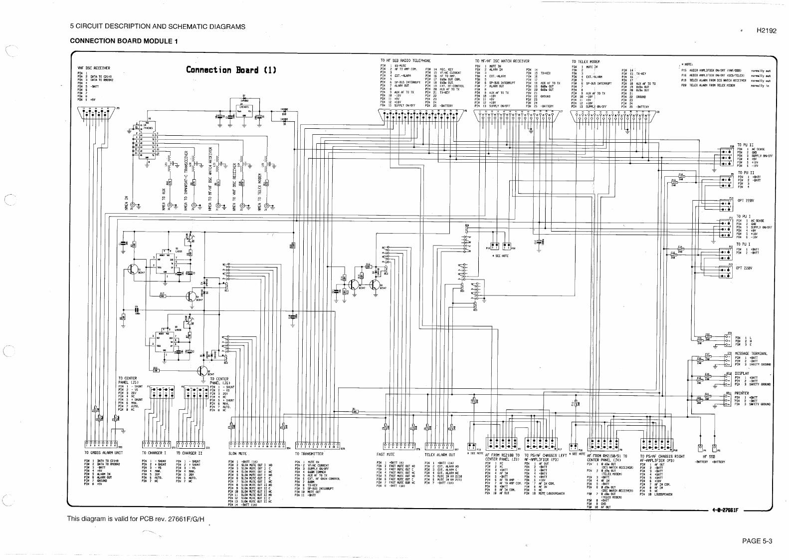

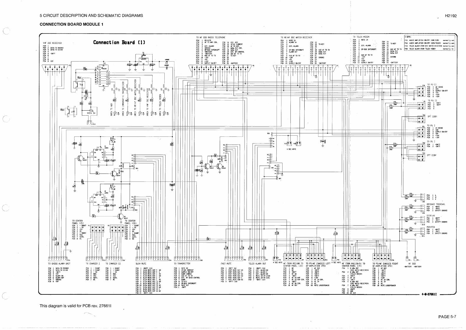
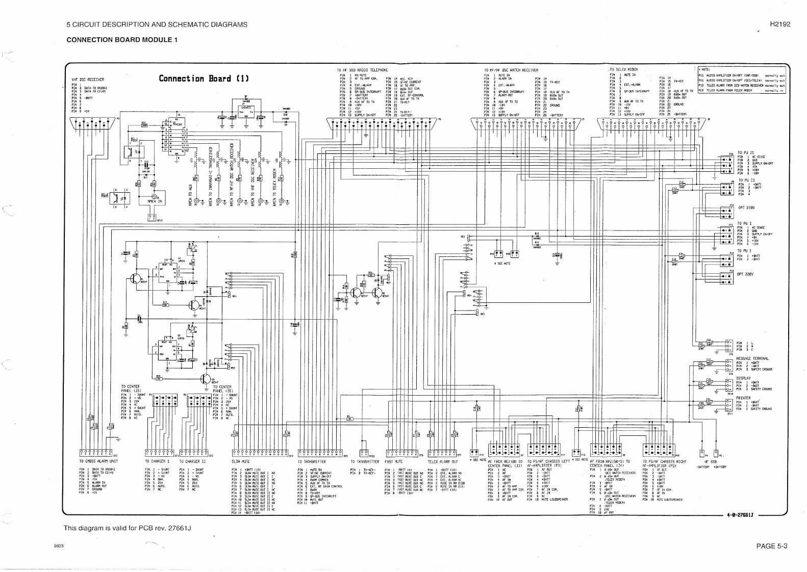
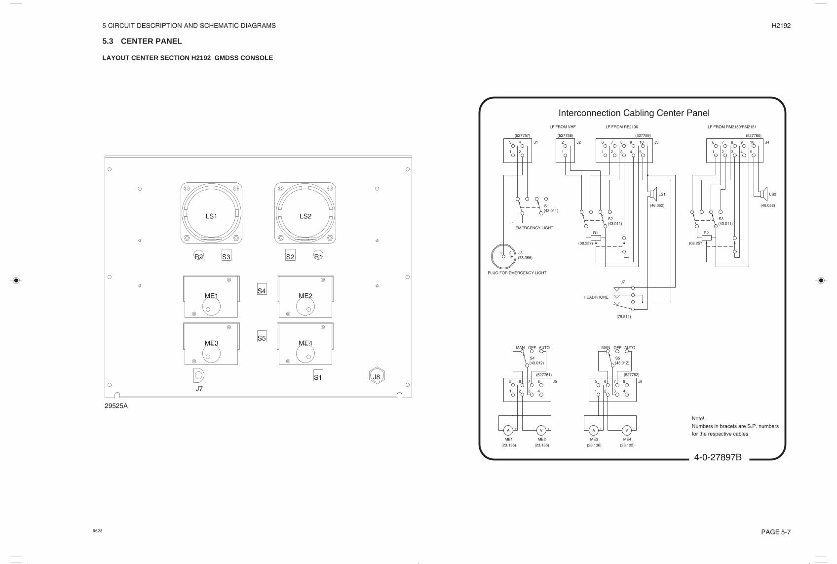
5 CIRCUIT DESCRIPTION AND SCHEMATIC DIAGRAMS H2192
5.3 CENTER PANEL
LAYOUT CENTER SECTION H2192 GMDSS CONSOLE
29525A
LS1 LS2
R1S2S3R2
ME1 ME2
ME3 ME4
S4
S5
S1
J7
J8
PAGE 5-7
4-0-27897B
Interconnection Cabling Center Panel
6 7 8 109
4 5321
J4
LF FROM RM2150/RM2151
LS2
R2R1
LS1
LF FROM RE2100
J3
1 2 3 54
9 108762
1
J2
LF FROM VHF
J7
HEADPHONE
43
1 2
J1
J821
PLUG FOR EMERGENCY LIGHT
EMERGENCY LIGHT
J5
1 2 3 4
8765
A- +
ME1 ME2
+- V V- +
ME4ME3
+- A
5 6 7 8
4321
J6
(527761)
(527757) (527758) (527759) (527760)
(527762)
(23.136) (23.135) (23.136) (23.135)
(78.511)
(46.052)(46.052)
(78.356)
Note!
Numbers in bracets are S.P. numbers
for the respective cables.
(43.011)S1
S2(43.011) (43.011)
S3
(08.257)(08.257)
AUTOOFFMAN
S5(43.012)(43.012)
S4
MAN OFF AUTO
9623
PAGE 5-9
5 CIRCUIT DESCRIPTION AND SCHEMATIC DIAGRAMS H2192
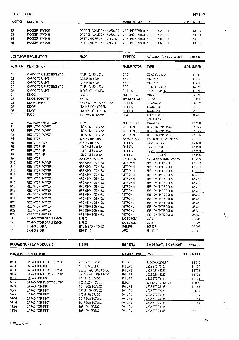
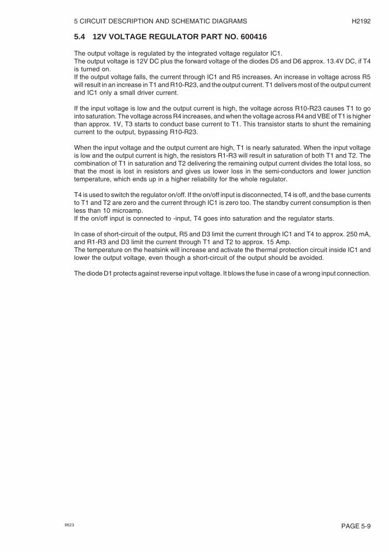
5.4 12V VOLTAGE REGULATOR PART NO. 600416
The output voltage is regulated by the integrated voltage regulator IC1.The output voltage is 12V DC plus the forward voltage of the diodes D5 and D6 approx. 13.4V DC, if T4is turned on.If the output voltage falls, the current through IC1 and R5 increases. An increase in voltage across R5will result in an increase in T1 and R10-R23, and the output current. T1 delivers most of the output currentand IC1 only a small driver current.
If the input voltage is low and the output current is high, the voltage across R10-R23 causes T1 to gointo saturation. The voltage across R4 increases, and when the voltage across R4 and VBE of T1 is higherthan approx. 1V, T3 starts to conduct base current to T1. This transistor starts to shunt the remainingcurrent to the output, bypassing R10-R23.
When the input voltage and the output current are high, T1 is nearly saturated. When the input voltageis low and the output current is high, the resistors R1-R3 will result in saturation of both T1 and T2. Thecombination of T1 in saturation and T2 delivering the remaining output current divides the total loss, sothat the most is lost in resistors and gives us lower loss in the semi-conductors and lower junctiontemperature, which ends up in a higher reliability for the whole regulator.
T4 is used to switch the regulator on/off. If the on/off input is disconnected, T4 is off, and the base currentsto T1 and T2 are zero and the current through IC1 is zero too. The standby current consumption is thenless than 10 microamp.If the on/off input is connected to -input, T4 goes into saturation and the regulator starts.
In case of short-circuit of the output, R5 and D3 limit the current through IC1 and T4 to approx. 250 mA,and R1-R3 and D3 limit the current through T1 and T2 to approx. 15 Amp.The temperature on the heatsink will increase and activate the thermal protection circuit inside IC1 andlower the output voltage, even though a short-circuit of the output should be avoided.
The diode D1 protects against reverse input voltage. It blows the fuse in case of a wrong input connection.
9623


5 CIRCUIT DESCRIPTION AND SCHEMATIC DIAGRAM H2192
PAGE 5-13
5.5 RIGHT HAND SECTION
29533A
MF
/HF
DS
CA
eria
l
Tel
ex m
odem
M
F/H
F D
SC
Aer
ial
H1223 H1223
9623
5 CIRCUIT DESCRIPTION AND SCHEMATIC DIAGRAM H2192
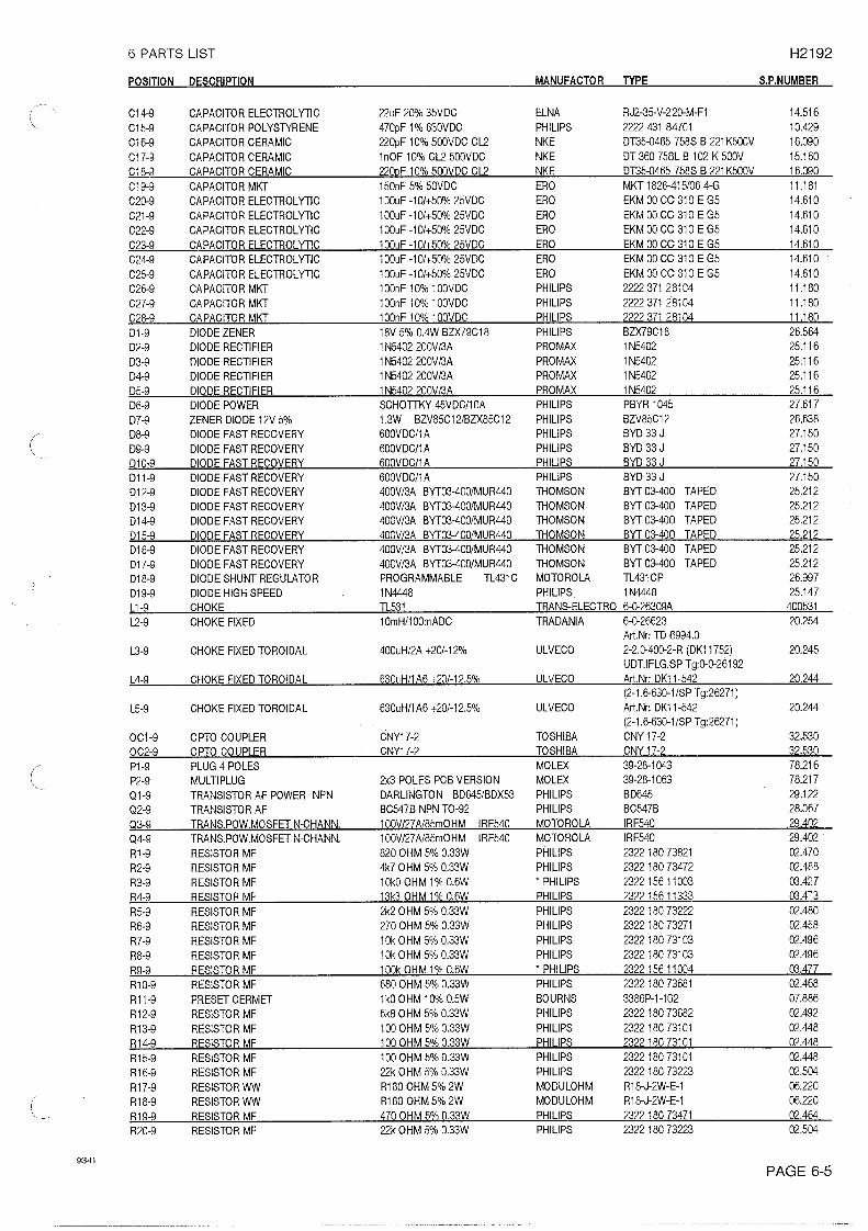
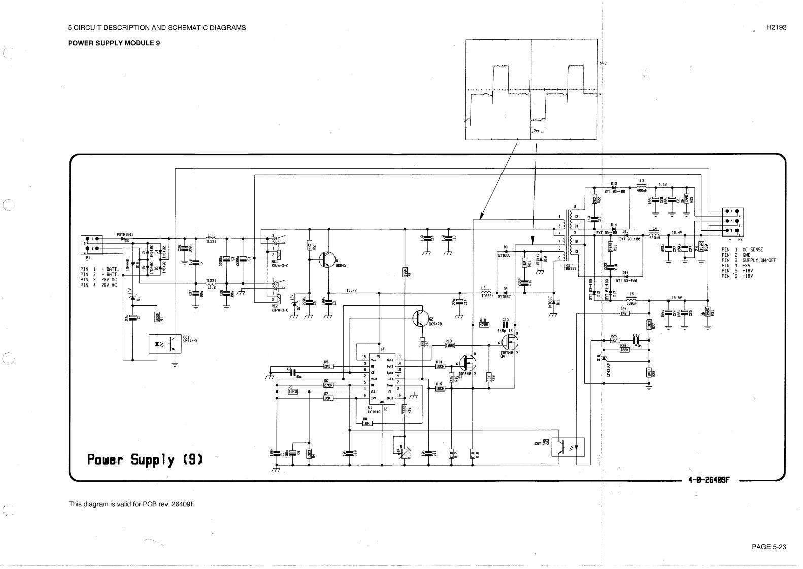
5.9 POWER SUPPLY MODULE 9 PART NO. 626409
The power supply is an isolated forward switch mode converter. It converts a 24V -10% +30% DC voltageto all the necessary voltages for the RE2100 and the control circuits in the transmitter. These voltagesare ±19V and +9.5V.Most of the necessary amplifiers, flip-flops etc. are contained in the ICU1. The only exception from this,is the secondary voltage sense D18.C2, C26, C27, L1, C3, C4 and C12, C13 are the input filter. The 12V DC supply voltage for U1 is suppliedto R2, D7, C8, Q4 and C9 during starting-up. When the converter is in function it is supplied by L2 andD8, D9. This voltage is approx. 15 Volt and forces Q1 to turn off. This configuration reduces the powerloss in Q1. R5 and C7 determine the oscillator frequency to approx. 50 kHz.The +18V DC output voltage is sensed by D18 via the voltage divider R27 and R28. D18 is an integratedshunt regulator. If the voltage on the sense input (R27/R28 common point) is higher than 2.5V, then theD18 starts conducting. In this case, current starts running in the optocoupler diode OC2.R26 is a DC feed-back and R25/C19 is an AC feed-back.R24 limits the current in the optocoupler diode.When current runs in the optocoupler diode, the optocoupler transistor (OC2) starts conducting nearlythe same current. This current results in a voltage across R6. This voltage is connected to the noninverting input of the internal error amplifier of U1. The internal error amplifier is fixed to a gain of 2 byR7 and R8.The output MOS transistor current is sensed by R17 and R18. The current signal is then led to the currentsense amplifier input, pin 4. The R15 and C11 is a lowpass filter to remove noise. The emitter of Q2 followsthe ramp voltage on the oscillator capacitor C7. R12 adds some of this ramp signal to the current signal.This is necessary to avoid sub-harmonic oscillations when the duty cycle is higher than 50%.The voltage on pin 1 determines the clamp voltage for the error voltage and thus also the max. currentin the output MOS transistors. This voltage is determined by R3 and R4. The capacitor C6 is the softstart capacitor, making the duty cycle and the output voltage rise slowly.The two pulse width modulated outputs are led to the two output MOS transistors by R13 and R14. Thesetwo resistors slow down the rising time of the MOS transistors to prevent spurious oscillations.R16 and R20 ensure that the transistors always stay off when the IC U1 is off.R19, C15 and R21, C16 and R22, C17 and R23, C18 are snuppers reducing oscillation due to straycapacitors and stray inductions in the transformer TR1.D12 to D17 and L3 to L5 and C20 to C25 are the three output rectifiers and filters.The input voltage is sensed by a 0.35 Volt shut down terminal pin 16 of U1 via R9, R10 and R11.If the supply voltage is higher than approx. 45V DC, the converter stops.
PAGE 5-159623
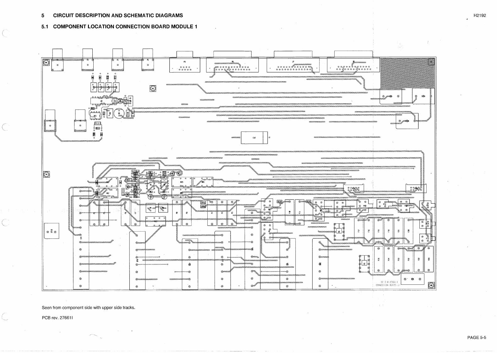
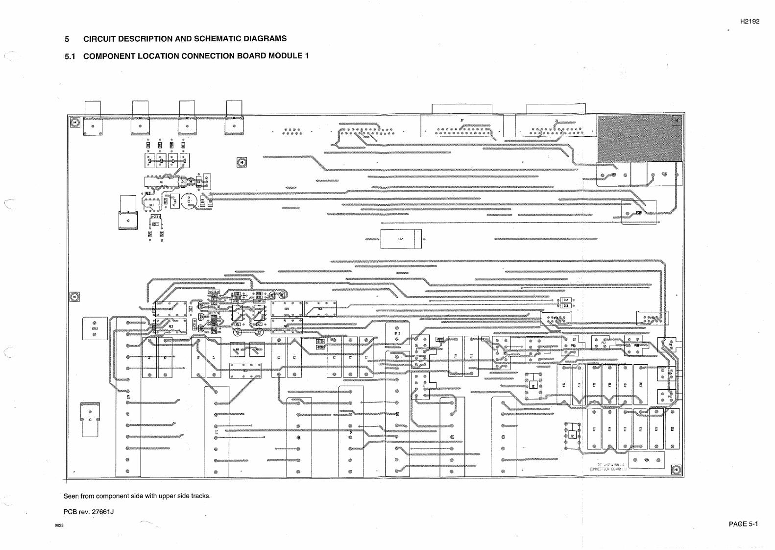
5 CIRCUIT DESCRIPTION AND SCHEMATIC DIAGRAMS H2192
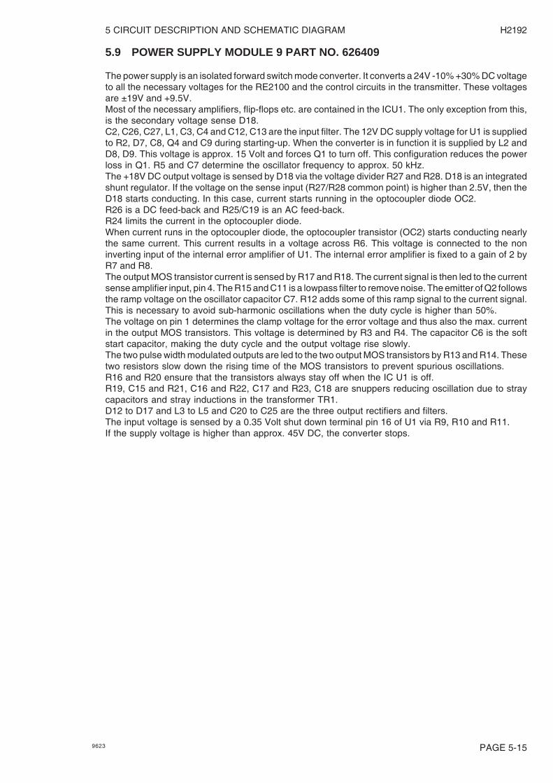
COMPONENT LOCATION POWER SUPPLY MODULE 9
Seen from component side with upper side tracks.
Seen from component side with lower side tracks.PCB rev. 26409F
PAGE 5-16 9623
5 CIRCUIT DESCRIPTION AND SCHEMATIC DIAGRAM H2192
PAGE 5-199623
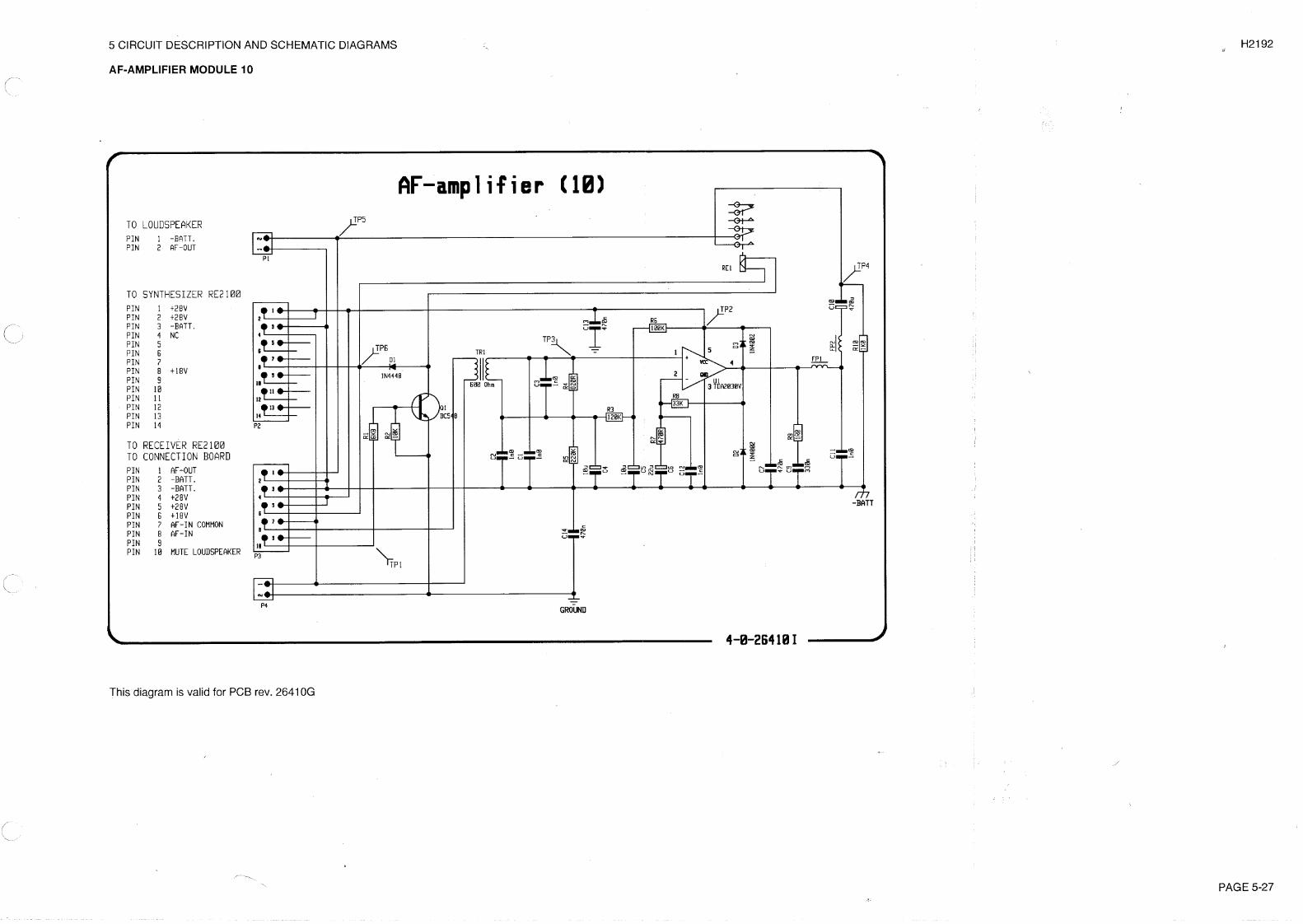
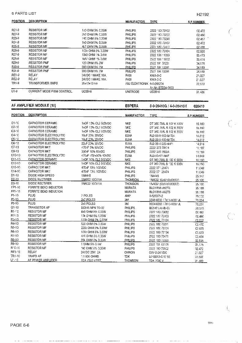
5.10 AF-AMPLIFIER (MODULE 10) PART NO. 626410
The audio amplifier is an integrated circuit TDA2030 U1, and it is supplied from the 28 Volt supply for thePA module. To insulate the battery from ground, there is a transformer TR1 at the input of the amplifier.RE1 and Q1 form a muting circuit for the loudspeaker. This circuit is controlled from the processor.

5 CIRCUIT DESCRIPTION AND SCHEMATIC DIAGRAMS H2192
PAGE 5-20 9623
COMPONENT LOCATION AF-AMPLIFIER MODULE 10
Seen from component side with upper side tracks.
Seen from component side with lower side tracks.
PCB rev. 26410G