Technical Letter Report (TLR-RES/DE/CIB-2020-08) Survey of ...
124
Letter Report TLR-RES/DE/CIB-2020-08 SURVEY OF MODELING AND SIMULATION TECHNIQUES FOR ADVANCED MANUFACTURING TECHNOLOGIES VOLUME I – PREDICTING INITIAL MICROSTRUCTURES Date: September 2020 Prepared in response to Task 1C in NRC Advanced Manufacturing Technologies Action Plan, Revision 1 (ADAMS Accession No. ML19333B980), by: Andrea Nicolas Argonne National Laboratory Aritra Chakraborty Argonne National Laboratory Noah Paulson Argonne National Laboratory Mark C. Messner Argonne National Laboratory NRC Project Manager: Shah Malik Senior Materials Engineer Component Integrity Branch Division of Engineering Office of Nuclear Regulatory Research U.S. Nuclear Regulatory Commission Washington, DC 20555–0001
Transcript of Technical Letter Report (TLR-RES/DE/CIB-2020-08) Survey of ...
Letter Report TLR-RES/DE/CIB-2020-08
SURVEY OF MODELING AND SIMULATION TECHNIQUES FOR ADVANCED MANUFACTURING TECHNOLOGIES
VOLUME I – PREDICTING INITIAL MICROSTRUCTURES
Date:
September 2020 Prepared in response to Task 1C in NRC Advanced Manufacturing Technologies Action Plan, Revision 1 (ADAMS Accession No. ML19333B980), by:
Andrea Nicolas Argonne National Laboratory Aritra Chakraborty Argonne National Laboratory Noah Paulson Argonne National Laboratory Mark C. Messner Argonne National Laboratory
NRC Project Manager: Shah Malik Senior Materials Engineer Component Integrity Branch
Division of Engineering Office of Nuclear Regulatory Research U.S. Nuclear Regulatory Commission Washington, DC 20555–0001

DISCLAIMER This report was prepared as an account of work sponsored by an agency of the U.S. Government. Neither the U.S. Government nor any agency thereof, nor any employee, makes any warranty, expressed or implied, or assumes any legal liability or responsibility for any third party's use, or the results of such use, of any information, apparatus, product, or process disclosed in this publication, or represents that its use by such third party complies with applicable law.

This report does not contain or imply legally binding requirements. Nor does this report establish or modify any regulatory guidance or positions of the U.S. Nuclear Regulatory Commission and is not binding on the Commission.

ANL-20/21
Survey of Modeling and Simulation Techniques for Advanced Manufacturing Technologies Volume I – Predicting Initial Microstructures
Applied Materials Division

About Argonne National Laboratory
Argonne is a U.S. Department of Energy laboratory managed by UChicago Argonne, LLC under contract DE-AC02-06CH11357. The Laboratory’s main facility is outside Chicago, at 9700 South Cass Avenue, Argonne, Illinois 60439. For information about Argonne and its pioneering science and technology programs, see www.anl.gov.
DOCUMENT AVAILABILITY
Online Access: U.S. Department of Energy (DOE) reports produced after 1991 and a growing number of pre-1991 documents are available free via DOE’s SciTech Connect (http://www.osti.gov/scitech/)
Reports not in digital format may be purchased by the public from the National Technical Information Service (NTIS):
U.S. Department of Commerce National Technical Information Service 5301 Shawnee Rd Alexandria, VA 22312 www.ntis.gov Phone: (800) 553-NTIS (6847) or (703) 605-6000 Fax: (703) 605-6900 Email: [email protected]
Reports not in digital format are available to DOE and DOE contractors from the Office of Scientific and Technical Information (OSTI):
U.S. Department of Energy Office of Scientific and Technical Information P.O. Box 62 Oak Ridge, TN 37831-0062 www.osti.gov Phone: (865) 576-8401 Fax: (865) 576-5728 Email: [email protected]
Disclaimer This report was prepared as an account of work sponsored by an agency of the United States Government. Neither the United States Government nor any agency thereof, nor UChicago Argonne, LLC, nor any of their employees or officers, makes any warranty, express or implied, or assumes any legal liability or responsibility for the accuracy, completeness, or usefulness of any information, apparatus, product, or process disclosed, or represents that its use would not infringe privately owned rights. Reference herein to any specific commercial product, process, or service by trade name, trademark, manufacturer, or otherwise, does not necessarily constitute or imply its endorsement, recommendation, or favoring by the United States Government or any agency thereof. The views and opinions of document authors expressed herein do not necessarily state or reflect those of the United States Government or any agency thereof, Argonne National Laboratory, or UChicago Argonne, LLC.
Andrea Nicolas Aritra Chakraborty Noah Paulson Mark C. Messner
ANL-20/21
Survey of Modeling and Simulation Techniques for Advanced Manufacturing Technologies Volume I – Predicting Initial Microstructures
Applied Materials Division Argonne National Laboratory August 2020 Prepared for the U.S. Nuclear Regulatory Commission under interagency agreement 31310019F0057 with the U. S. Department of Energy Prepared by
i
ABSTRACT
This report summarizes the current state of modeling and simulation methods for predicting the initial structure and properties of material in components assembled using advanced manufacturing technologies (AMTs). The report is the first volume in a two-volume series. This first volume focuses on predicting initial microstructures of AM material. The second volume discusses predicting material properties given the initial microstructure. The focus is on technologies of particular relevance to the design and manufacture of nuclear reactor components. The purpose of the report is to help develop the technical knowledge base to support regulatory decisions that will be needed to assess nuclear components manufactured with AMTs as these components are installed at nuclear power plants (NPPs). The report develops a list of AMTs of particular interest to the NRC and summarizes the key microstructural features and corresponding processing parameters relevant to each technology. Further sections describe available physically-based and data-driven prediction methods and survey widely available software tools. The report concludes with a summary of gaps that may be of particular interest to the NRC when evaluating modeling and simulation methods for AMTs.

iii
EXECUTIVE SUMMARY
This report provides a summary of the current state-of-the art in predicting the microstructure of materials resulting from Advanced Manufacturing Technologies (AMTs). The report is the first volume in a two-volume series. The second volume focuses on predicting the performance of the material given the initial microstructure. Taken together, these reports describe the current and future feasibility of predicting the performance of a component starting from basic processing information.
This report describes the current state of modeling and simulation techniques through an extensive literature view, identifies and describes available modeling and simulation software and provides a gap analysis and a list of recommendations. The gap analysis and recommendations focus on potential future regulatory issues in using modeling and simulation to inform and assess the performance of AMT components.
The report contains a brief summary of the AMTs of interest to nuclear systems: Laser Power Bed Fusion (LPBF), Directed Energy Deposition (DED), electron beam (e-beam) welding, and Power Metallurgy-Hot Isostatic Pressing (PM-HIP) [6]. The report also contains a brief overview of work on the binder jet, diffusion bonding, and cold spray processes. These are, for the most part, the technologies identified a Nuclear Energy Institute (NEI) roadmap on the qualification of AMT components [1], which also notes that cold spray techniques may also be used in repairs, spent fuel storage, and future reactors. This report identifies the key processing parameters and corresponding microstructural features for each technology of interest. To aid in categorizing the wide array of AMT methods, the report divides the technologies into fusion-based (PBF, DED, and e-beam) and diffusion-based (PM-HIP) processes.
The report then summarizes the current state of the art in informing and assessing material microstructure using physics-based and data-driven techniques. Key conclusions include the need for better methods of length- and time-scale bridging for the physics-based methods, collation or generation of larger microstructural databases for the data-driven methods, and the development of community accepted validation benchmarks for the different AMTs of interest. A subsequent chapter provides a summary of the available software tools implementing the simulation methods identified earlier in the report.
Based on the survey and gap analysis contained in the report, the key recommendations provided here are:
• Models for predicting residual stress and distortion in fusion processes are already a well-validated, viable commercial technology
• Simulation techniques for modeling densification in sintering and PM-HIP methods will be commercially available in the near-term
• Detailed complete simulations for predicting initial microstructure will take longer to be put into industrial use
• For the advanced microstructural simulation techniques, new methods will be needed to bridge length and time scales in order to develop practical and complete process models
iv
• Data-driven techniques will help bridge the gap between length scales in simulation methods and will increasingly see direct use on large datasets collected during fabrication
• Benchmark problems can increase manufacturer and regulator confidence in modeling and simulation methods
• Other AMTs and modeling techniques may need to be considered in the near future; for example, the authors are aware of vendor interest in cold spray and explosion bonding techniques for cladding.
The report conclusions strongly emphasize the need to develop benchmark problems for testing and validating modeling and simulation techniques. One challenge in this will be developing methods for the standard reporting of processing method, processing parameters, and the resulting microstructure.

v
ACRONYMS AND ABBREVIATIONS
The following is a list of acronyms and abbreviations used throughout the document: Acronym Expression AMRC Advanced Manufacturing Research Centre AMT Advanced Manufacturing Technologies ASME American Society of Mechanical Engineers CA Cellular Automata CAD Computer Aided Design CAFD Cellular Automata Finite Difference method CAFE Cellular Automata Finite Element method CALPHAD Computer Coupling of Phase Diagrams and Thermochemistry CFD Computational Fluid Dynamics CNC Computer Numerical Control CP Crystal Plasticity DED Directed Energy Deposition DEM Discrete Element Method DLM Direct Laser Melting ebeam Electron beam EBM Electron Beam Melting EBR Experimental Breeding Reactor EBW Electron Beam Welding EPRI Electric Power Research Institute FAST Field Assisted Sintering Technique FEA Finite Element Analysis GE General Electric GSA Global Sensitivity Analysis HIP Hot Isostatic Pressing HPC High Performance Computing ITER International Thermo-Nuclear Experimental Reactor JMAK Johnson-Mehl-Avrami-Kolomogorov relation (recrystallization kinetics) LWR Light Water Reactor MC Monte Carlo M&S Modeling & Simulation ML Machine Learning NEI Nuclear Energy Institute PBF Powder Bed Fusion PM-HIP Powder Metallurgy Hot Isostatic Pressing SLM Selective Laser Melting SPS Spark Plasma Sintering SS Stainless Steel TBM Test Blanket Module VOF Volume of Fluid

vi
TABLE OF CONTENTS
Abstract ............................................................................................................................................ i Executive Summary ....................................................................................................................... iii Acronyms and abbreviations ............................................................................................................v Table of Contents ........................................................................................................................... vi Table of Figures ............................................................................................................................. ix List of Tables ................................................................................................................................. xi 1 Introduction ................................................................................................................................1
1.1 Motivation .........................................................................................................................1 1.2 Report Objectives .............................................................................................................1 1.3 Organization......................................................................................................................2
2 Applications of AMTs in nuclear systems .................................................................................5 2.1 AMTs of Interest ...............................................................................................................6
2.1.1 Fusion processes ...................................................................................................6 2.1.1.1 Powder-bed fusion .............................................................................................6 2.1.1.2 Directed energy deposition ................................................................................7 2.1.1.3 E-beam welding/ e-beam systems ......................................................................8
2.1.2 Diffusion processes .............................................................................................10 2.1.2.1 PM-HIP + diffusion bonding ...........................................................................10 2.1.2.2 Binder-jetting ...................................................................................................11
2.1.3 Other AMTs ........................................................................................................12 2.2 Comparison and Summary .............................................................................................13
3 Key microstructural characteristics and processing parameters ..............................................15 3.1 Introduction .....................................................................................................................15 3.2 Microstructural characteristics of interest .......................................................................16
3.2.1 Overview .............................................................................................................16 3.2.2 Grain size, shape, morphology, and texture ........................................................16 3.2.3 Void shape, size, and distribution .......................................................................17 3.2.4 Precipitate structure and phase distribution ........................................................17 3.2.5 Residual stress and distortion..............................................................................17 3.2.6 Surface roughness and finish ..............................................................................17
3.3 Key processing parameters .............................................................................................17 3.3.1 Fusion processes .................................................................................................17
3.3.1.1 Overview: melt pool solidification ..................................................................18 3.3.1.2 General parameters ..........................................................................................20 3.3.1.3 Parameters specific to powder bed fusion processes .......................................23 3.3.1.4 Parameters specific to directed energy deposition processes ..........................23 3.3.1.5 Parameters specific to laser heat sources .........................................................23 3.3.1.6 Parameters specific to electron beam heat sources ..........................................24 3.3.1.7 Postprocessing..................................................................................................24
3.3.2 Diffusional processes ..........................................................................................26 3.3.2.1 Overview: diffusion, pore collapse, and recrystallization ...............................26 3.3.2.2 General parameters ..........................................................................................29 3.3.2.3 Processing parameters specific to PM-HIP......................................................30 3.3.2.4 Processing parameters specific to binder jet ....................................................31
vii
3.4 Summary and Recommendations ...................................................................................31 4 Physics-based prediction methods ...........................................................................................33
4.1 Predicting residual stress and distortion .........................................................................33 4.1.1 General overview of AMT modeling ..................................................................33
4.1.1.1 Thermomechanical modeling ...........................................................................33 4.1.1.2 Representing residual strain .............................................................................34 4.1.1.3 Two-step numerical analysis ............................................................................34 4.1.1.4 Element activation ...........................................................................................34
4.1.2 Modeling across length scales ............................................................................36 4.1.3 Challenges ...........................................................................................................37
4.2 Predicting melt pool geometry ........................................................................................37 4.2.1 Introduction .........................................................................................................37 4.2.2 Modeling the melt pool .......................................................................................37
4.2.2.1 Heat source model ............................................................................................37 4.2.2.2 Material properties ...........................................................................................38 4.2.2.3 Thermodynamics methods ...............................................................................39 4.2.2.4 Fluid dynamics method ....................................................................................40
4.2.3 Limitations and challenges .................................................................................41 4.2.3.1 Homogeneous vs inhomogeneous media .........................................................41 4.2.3.2 Multiphysics modeling.....................................................................................41
4.2.4 Use in optimizing processing parameters ...........................................................42 4.3 Predicting solidification from melt .................................................................................42
4.3.1 Processing maps ..................................................................................................42 4.3.2 Simulation methods for grain growth and nucleation .........................................44
4.3.2.1 Cellular automata .............................................................................................44 4.3.2.2 Phase field ........................................................................................................45 4.3.2.3 Other techniques ..............................................................................................47
4.3.3 Challenges in deriving comprehensive models ...................................................47 4.4 Predicting grain growth and densification ......................................................................48
4.4.1 Modeling recrystallization ..................................................................................48 4.4.2 Modeling densification .......................................................................................50
4.4.2.1 Continuum methods .........................................................................................50 4.4.2.2 Discrete methods ..............................................................................................51
4.4.3 Challenges developing complete process models ...............................................52 4.5 Summary and Recommendations ...................................................................................53
5 Data-based prediction methods ................................................................................................55 5.1 Introduction .....................................................................................................................55 5.2 Processing-structure maps ..............................................................................................55 5.3 Machine learned processing-structure relationships .......................................................56 5.4 Uncertainty quantification and sensitivity analysis ........................................................57 5.5 Summary and future outlook ..........................................................................................58
6 Survey of available modeling tools..........................................................................................61 6.1 Solid/thermal modeling tools for predicting residual stress and distortion ....................63 6.2 Fluid or hydrodynamic tools for melt and resolidification .............................................64 6.3 Phase field tools for predicting solidification microstructures .......................................65
7 Key Recommendations ............................................................................................................67

viii
8 Conclusions ..............................................................................................................................77 Acknowledgements ........................................................................................................................79 References ......................................................................................................................................81
ix
TABLE OF FIGURES
Figure 1. Schematic of Powder-Bed Fusion (PBF) process. ......................................................................... 7 Figure 2. Schematic of Directed Energy Deposition (DED) process with powder feed. .............................. 8 Figure 3. Schematic of Electron Beam Welding (EBW) process with wire feeder. ..................................... 9 Figure 4. Schematic of PM-HIP process. .................................................................................................... 10 Figure 5. Schematic of Binder Jetting process with colored binder. .......................................................... 11 Figure 6. Illustration of the cold spray process. .......................................................................................... 12 Figure 7. Grain morphology of DED of TC18 titanium alloy with different morphologies given changing processing parameters. Taken from [30]. .................................................................................................... 15 Figure 8. Main grain characteristics affecting material properties.............................................................. 16 Figure 9. Micrograph of AlSi10Mg produced via SLM using a unidirectional horizontal scanning strategy. The melt pools with half cylindrical shape and the anisotropic microstructure can be observed in the image. Taken from [92]. ....................................................................................................................... 18 Figure 10. Schematic of surface conduction and keyhole mode ................................................................. 20 Figure 11. Schematic of build direction and scanning strategy during AMT ............................................. 22 Figure 12. Overview of the three heat treatment categories ....................................................................... 25 Figure 13. Different types of diffusion mechanisms ................................................................................... 27 Figure 14. Microstructures generated for Ti64 PM-HIP material given different types of powders. (a) is Φ33 x 58 atomized and (b) is Φ33 x 58 milled. Taken from [189]. ............................................................ 30 Figure 15. Schematic of a thermomechanical model. The calculated thermal gradients from the AMT are implemented onto a mechanical model to obtain residual stresses and deformation .................................. 33 Figure 16. Schematic of different types of element activation methods. .................................................... 35 Figure 17. Schematic of heat source models. Geometric models have a defined volume whereas absorption models have a gradual transition. .............................................................................................. 38 Figure 18. Schematic of the heat transfer modes and general melt pool phenomena in AMTs .................. 40 Figure 19. Representative solidification processing map. .......................................................................... 43 Figure 20. Typical cellular automata discretization of a domain into a regular grid of cells with each cell here being in either the Solid, Interface, or Liquid state. ............................................................................ 44 Figure 21. A typical phase field representation of a two-phase problem. Phase are represented with a single order parameter, φ. A value of φ = 0 indicates the first phase (for example, liquid) and a value of φ = 0 indicates the second phase (for example solid). The order parameter is a continuous field so there is a blurred region between the two phases. The phase boundary is often fixed to theφ = 0.5 contour. ......... 46


xi
LIST OF TABLES
Table 1. Advantages/Disadvantages of various AMTs. .............................................................................. 14 Table 2. Summary of available modeling and simulation tools for initial structure of AMT components. 61 Table 3. Summary of critical issues and priorities for AMT modeling ...................................................... 73

1
1 Introduction
1.1 Motivation
Components manufactured with Advanced Manufacturing Technologies (AMTs) are likely to enter the nuclear supply chain in the near future, either as replacement components in the current Light Water Reactor (LWR) fleet or in new construction of LWRs or advanced non-LWRs [1]. AMTs could decrease costs by providing components faster and cheaper than current conventional manufacturing practices. Additionally, the new geometric and material options enabled by AMT processes could transform the reactor design process by providing designers additional design flexibility. Given the national interest in advancing these new manufacturing techniques [2] and the potential nuclear applications, nuclear regulators will likely be called upon to evaluate designs and replacement components involving AMTs.
Compared to conventional manufacturing processes, AMTs will see greater use of modeling and simulation (M&S) techniques in manufacturing components and assessing and evaluating final material properties. There are several reasons for the increased interest in integrating M&S into the manufacturing process:
1. There is a broader interest in using M&S to improve process efficiency, reduce waste, and improve material properties in the manufacturing community, not specific to AMTs.
2. M&S tools can help put AMT processes into service more quickly by shortening the time required to optimize processing parameters and upscale the production rate in between the invention of a new technique and putting it into industrial use.
3. Generally speaking, AMT processes are more tied to computer control than current manufacturing processes. This means there is a large dataset which M&S tools can take advantage of (for example, via in situ process monitoring) and that simulations can be directly coupled into the manufacturing process via computer control.
AMTs, broadly defined, are new manufacturing techniques not currently in nuclear service that involve novels ways to manufacture components from raw materials, join components together, or overlay prebuilt components with a coating or cladding. While this definition includes a wide variety of new manufacturing techniques, Chapter 2 limits the scope of this report to a few selected technologies of particular interest to the nuclear industry, as identified in a Nuclear Energy Institute (NEI) roadmap on regulatory acceptance of AMTs [1].
1.2 Report Objectives
A key aspect of M&S for AMTs is predicting the initial material microstructure, defect structure, component integrity, and material properties of parts. Accomplishing these modeling and simulation objectives would accelerate the industrial adoption of AMT processes and their associated benefits. Moreover, if vendors rely on modeling and simulation coupled with validation testing data to ensure the quality of AMT components the NRC and other regulators would have a strong regulatory interest in the accuracy and completeness of the M&S tools.
This report focuses on methods for predicting initial microstructures. The reason is that microstructural prediction determines the other initial properties of interest to regulators
2
(component integrity, material properties, and defect structures). The report adopts a broad definition of microstructure including material defects, like porosity or unwanted phase segregation, and covers gross structural defects introduced by thermal stress in the sections covering the prediction of residual stress and distortion. The majority of the M&S research on AMTs surveyed here adopts the material science perspective that predicting the material microstructure is equivalent to predicting material properties. The exceptions are some of the data-driven prediction methods surveyed in Chapter 5, which are covered in detail in that section of the report. Moreover, this report is the first in a two-volume series. The second volume covers the prediction of material properties given a description of the material microstructure. Taken together, these two reports address the prediction of initial material properties from the AMT processing parameters.
The objectives of this report are to survey available modeling and simulation techniques, provide an assessment and gap analysis on the current state of the art, and provide specific recommendations on future activities related to modeling and simulation (M&S) for AMTs that may be relevant to regulators. The purpose of the report is then to help develop the regulatory knowledge base that will be needed to assess AMT nuclear components when they come before the NRC.
The field of research covering advanced manufacturing is broad and rapidly expanding and so this report cannot be fully comprehensive. Limiting the scope to the AMTs of most interest to the nuclear industry helps focus the information covered here, though M&S techniques are often broadly applicable to more than one type of manufacturing process. Limiting the survey to current or emerging nuclear materials would eliminate a wide body of literature on aerospace and biomedical applications and so generally the report only restricts the AMT techniques and not the underlying material systems.
1.3 Organization
To help focus the review, the report categorizes AMTs into fusion and diffusion/mechanical processes. This division has its roots in classical welding techniques [3] and categorizes the AMTs specifically surveyed here with reasonable accuracy. This division supports a survey of broadly applicable simulation techniques first before focusing on applications specifically relevant to the AMTs of interest. The report further divides modeling methods into physics-based or data-driven categories. The former are classical methods based on understanding the underlying material physics, where typically tools such as Finite Element Analysis (FEA) or Computational Fluid Dynamics (CFD) are used to implement a discretized partial differential equation boundary value problem representing some set of physical conservation laws. The latter are newer, machine learning approaches directly correlating processing parameters to microstructure using an experimental or simulation database.
Specifically, Chapter 2 covers potential applications of AMTs in nuclear systems and describes the set of AMTs that are the focus of this report. Chapter 3 provides context for the M&S methods surveyed here by describing key microstructural characteristics that will be of interest and the general processing parameters controlling the development of those characteristics. Chapters 1 and 5 then survey general categories of physics-based and data-driven M&S methods that have been applied to AMT processes. Chapter 1 provides a survey of widely-available software tools

3
implementing these methods. Finally, Chapter 1 summarizes the report and provides a set of specific gaps and recommendations relevant to the NRC’s regulatory mission.


5
2 Applications of AMTs in nuclear systems There is a growing interest in using AMTs for nuclear applications given the potential advantages of reducing costs, increasing safety, and simplifying the manufacturing of complex components [4]. Potential applications include the fabrication of nuclear vessels, pipes, and fuel components for advanced reactors, which would address the current concern of the U.S. infrastructure lack of capability to supply advanced reactor components at a high construction rate given the limitations of traditional manufacturing methods [5]. AMTs also show promise in reconstructing and repairing legacy components in existing reactors, where oftentimes the original design and/or manufacturer is no longer available [1]. Since the nuclear industry is likely to use AMTs in the fabrication of key components that will need regulatory oversight, it is of great interest to identify the AMTs that will be likely used to create components subjected to NRC approval [6].
The nuclear industry is already evaluating the use of different AMTs for their individual needs. NuScale has investigated Powder Metallurgy Hot Isostatic Pressing (PM-HIP) as a viable method to manufacture a pressure vessel upper head in a small modular reactor, which has a complex geometry and for which traditional manufacturing methods would prove to be highly inefficient [7]. GE-Hitachi has a similar interest in using AMTs for the manufacturing of advanced small modular reactor components. Currently, their efforts have focused on evaluating the performance of SS316L manufactured with laser Powder Bed Fusion (PBF), under corrosive and irradiated conditions [8], [9].
Many current examples focus on 316L as it has good mechanical properties at high temperatures, its resistance to corrosion, and its machinability. Full nuclear reactor components made of 316L have been manufactured via Electron beam melting (EBM) [10] and Selective Laser Melting (SLM) [11]. In non-fission reactors, SLM has been studied as an option for manufacturing the test blanket modules (TBMs) in the ITER with complex cooling channels [12]. An interesting advantage of the powder-based SLM is its ability to create an alloy from the basic element composition. As an example, SLM has been used to create V-6Cr-6Ti components directly from pre-alloy powder particles of pure vanadium, titanium and chromium [13]. Therefore, AMTs offer the option of creating stainless steel nuclear components form pure elemental powders, which could lead to cost savings and greater control of material quality [14].
Other studies examine the performance of SLM components exposed to reactor environmental conditions. One study addresses the stress corrosion cracking growth behavior of SLM-manufactured SS316L in the presence of a boiling water reactor environment [15]. This work finds the directionality of the SLM microstructure enhances crack growth rates by creating preferential directions crack propagation. To counter this issue, SLM components have been annealed to allow the material to recrystallize into an equiaxed microstructure.
Directed Energy Deposition (DED) has been considered for the production of reactor components made of ferritic-martensitic steels with complex geometries, such as the hex-ducts inside the Experimental Breeder Reactor II (EBR-II) [16]. Since DED components also exhibit performance issues due to directionality, heat treatments have been developed to redistribute the precipitates in the material and transform the mechanical behavior of the DED material from anisotropic to isotropic. DED can also clad components during manufacturing by changing the material locally during the process [17], with the added advantage of potentially lowering the risk of welding defects that usually occur during the traditional weld-overlay cladding process. DED used as an

6
in-situ cladding technique would ensure heat and corrosion resistant nuclear components that do not require any postprocessing.
Finally, electron beam welding (EBW) has been of interest for the manufacturing of large nuclear components [18] as it offers relatively fast processing rates and good penetration through thick-walled components. EBW was successfully used to build nuclear structures made of Ti64 and SS316L either by wire deposition or by the joining of subsections in a large nuclear vessel.
Reverse engineering often plays a role in AMTs for manufacturing of replacement parts for discontinued/legacy components, reconstruction and repair of components with unique geometries, and design optimization of an already existing part to improve plant performance [19]. These types of applications are especially significant in the nuclear industry since the existing components are increasingly becoming legacy parts that need to be efficiently repaired or replaced, and for which product redevelopment and manufacturing via traditional methods is not an option due to time constraints or the lack conventional manufacturing capabilities. Reverse engineering has been implemented in the nuclear sector by replacing a metallic pump impeller via 3D scanning and printing, and there are future plans of using Direct Laser Melting (DLM) to produce replacement parts of SS316L and Inconel 718 components subjected to irradiation [20]. Consequently, regulatory guidance such as BWRVIP-84 [21] have been revised to provide additional requirements for the use of materials produced by AMTs, with the end goal of ensuring adequate performance of AMT components.
2.1 AMTs of Interest
The techniques of interest for the manufacturing of critical nuclear components can be categorized into fusion and diffusion-based processes. For the fusion processes, melting of the powder/wire source material occurs during manufacturing of the component, whereas for diffusion processes the material never exceeds the melting temperature during the process. The following describes several AMTs assessed to be likely used for near-term nuclear applications, which is a need addressed by the NRC action plan [6]. Some of these techniques have been highlighted as critical for the nuclear industry by the DOE infrastructure plan [5]. The remainder of the report focuses on the AMTs described in this chapter.
2.1.1 Fusion processes
2.1.1.1 Powder-bed fusion
Powder-bed fusion (PBF) is an additive manufacturing technique in which an energy source selectively melts each layer of powder of the desired manufactured component inside a build chamber with an inert environment. Once a layer has been scanned, the piston of the build chamber moves downward and the piston of the powder chamber goes upward by a defined thickness. A roller/blade then transfers powder from the powder chamber to the build chamber, and the energy source repeats the selective melting of the material. This layer-by-layer scanning process is repeated until the part is complete, after which it is removed from the build chamber and any excess powder is removed with compressed air [22]. Typical materials available for powder-bed fusion

7
are titanium alloys, Inconel alloys, cobalt chrome, aluminum alloys, stainless steels and tool steels [23].
Figure 1. Schematic of Powder-Bed Fusion (PBF) process.
The PBF technique is a well-researched technique common in the automotive, aerospace, and biomedical industry, and as such there is extensive literature as well as a broad array of suppliers for both additive manufacturing services and machinery [22]–[24] for the manufacturing of non-critical components with complex geometries [25]. One of the main challenges that industries face is machine-to-machine consistency during manufacturing, which tends to complicate the qualification and certification of AMT processes and components [26]. Currently, these industries are actively working on improving the quality of PBF-generated components so that the technique can also be applied to safety-critical parts that require a long lifetime. Additionally, although powder-bed fusion tends to be used for the manufacturing of small parts that require a high level of precision, the largest commercially available machine, GE additive’s X line 2000R, is capable of building a volume up to 800 x 400 x 500 mm3 at a build rate up to 120 cm3/h [27]. GE additive has also released a prototype with an even bigger build volume of 1,100 x 1,100 x 300 mm3 and a similar build rate, which shows that this technique is also capable of manufacturing medium-scale components without compromising on precision.
2.1.1.2 Directed energy deposition
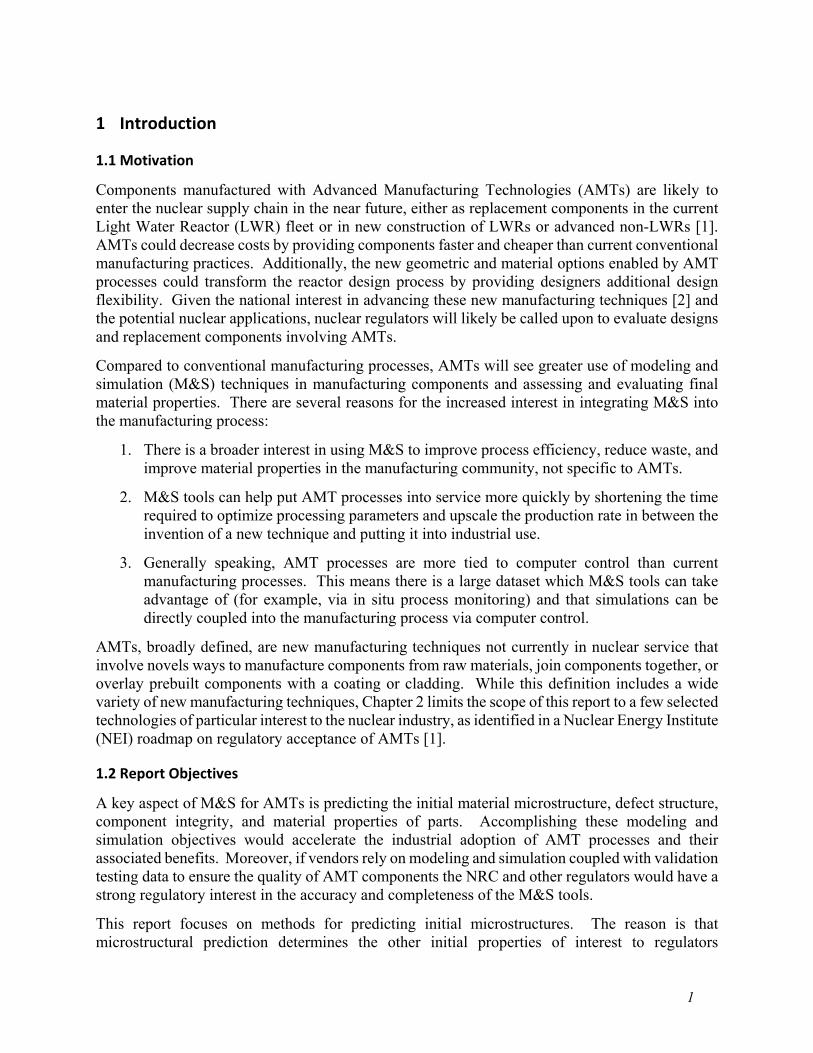
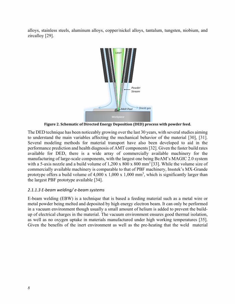
Directed energy deposition (DED) is a technique where a 4- or 5-axis nozzle moves around a fixed object, depositing powder or wire material onto surfaces while an energy source (laser, electron beam, plasma) directly melts the material upon deposition. Similar to PBF, this technique works layer by layer by adding material on top of the already deposited surface, with the advantage that this technique has a faster build rate (typically 6.5 to 20 lbs/h, compared to 0.44 lbs/h for powder bed fusion), which means that it is capable of creating large components in a significantly shorter time [28]. DED is compatible with a wide array of materials, including titanium alloys, Inconel
8
alloys, stainless steels, aluminum alloys, copper/nickel alloys, tantalum, tungsten, niobium, and zircalloy [29].
Figure 2. Schematic of Directed Energy Deposition (DED) process with powder feed.
The DED technique has been noticeably growing over the last 30 years, with several studies aiming to understand the main variables affecting the mechanical behavior of the material [30], [31]. Several modeling methods for material transport have also been developed to aid in the performance prediction and health diagnosis of AMT components [32]. Given the faster build rates available for DED, there is a wide array of commercially available machinery for the manufacturing of large-scale components, with the largest one being BeAM’s MAGIC 2.0 system with a 5-axis nozzle and a build volume of 1,200 x 800 x 800 mm3 [33]. While the volume size of commercially available machinery is comparable to that of PBF machinery, Insstek’s MX-Grande prototype offers a build volume of 4,000 x 1,000 x 1,000 mm3, which is significantly larger than the largest PBF prototype available [34].
2.1.1.3 E-beam welding/ e-beam systems
E-beam welding (EBW) is a technique that is based a feeding material such as a metal wire or metal powder being melted and deposited by high energy electron beam. It can only be performed in a vacuum environment though usually a small amount of helium is added to prevent the build-up of electrical charges in the material. The vacuum environment ensures good thermal isolation, as well as no oxygen uptake in materials manufactured under high working temperatures [35]. Given the benefits of the inert environment as well as the pre-heating that the weld material
9
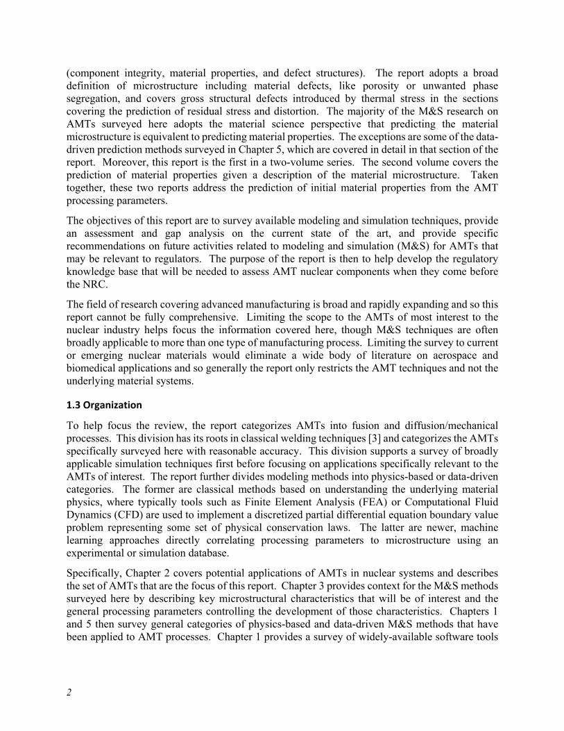
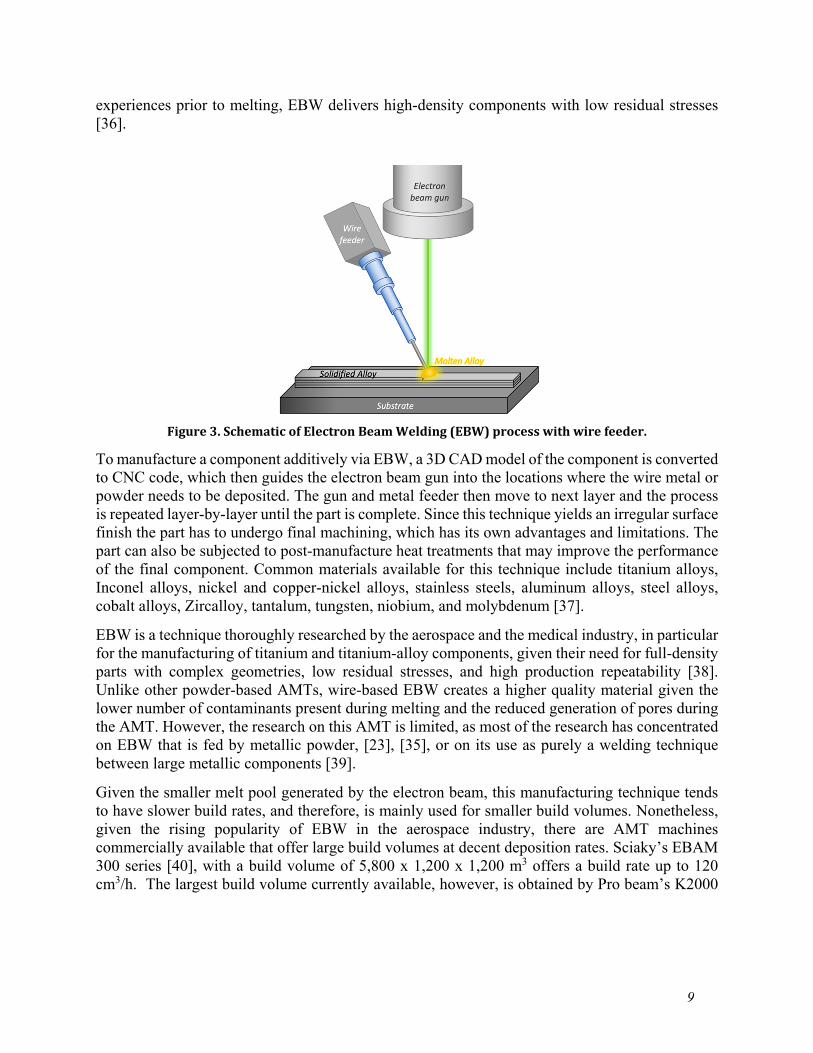
experiences prior to melting, EBW delivers high-density components with low residual stresses [36].
Figure 3. Schematic of Electron Beam Welding (EBW) process with wire feeder.
To manufacture a component additively via EBW, a 3D CAD model of the component is converted to CNC code, which then guides the electron beam gun into the locations where the wire metal or powder needs to be deposited. The gun and metal feeder then move to next layer and the process is repeated layer-by-layer until the part is complete. Since this technique yields an irregular surface finish the part has to undergo final machining, which has its own advantages and limitations. The part can also be subjected to post-manufacture heat treatments that may improve the performance of the final component. Common materials available for this technique include titanium alloys, Inconel alloys, nickel and copper-nickel alloys, stainless steels, aluminum alloys, steel alloys, cobalt alloys, Zircalloy, tantalum, tungsten, niobium, and molybdenum [37].
EBW is a technique thoroughly researched by the aerospace and the medical industry, in particular for the manufacturing of titanium and titanium-alloy components, given their need for full-density parts with complex geometries, low residual stresses, and high production repeatability [38]. Unlike other powder-based AMTs, wire-based EBW creates a higher quality material given the lower number of contaminants present during melting and the reduced generation of pores during the AMT. However, the research on this AMT is limited, as most of the research has concentrated on EBW that is fed by metallic powder, [23], [35], or on its use as purely a welding technique between large metallic components [39].
Given the smaller melt pool generated by the electron beam, this manufacturing technique tends to have slower build rates, and therefore, is mainly used for smaller build volumes. Nonetheless, given the rising popularity of EBW in the aerospace industry, there are AMT machines commercially available that offer large build volumes at decent deposition rates. Sciaky’s EBAM 300 series [40], with a build volume of 5,800 x 1,200 x 1,200 m3 offers a build rate up to 120 cm3/h. The largest build volume currently available, however, is obtained by Pro beam’s K2000
10
AMT machine, which was developed at the Nuclear Advanced Manufacturing Research Centre (AMRC) and has a maximum build size of 6,400 x 4,000 x 3,200 mm3 [41].
2.1.2 Diffusion processes
2.1.2.1 PM-HIP + diffusion bonding
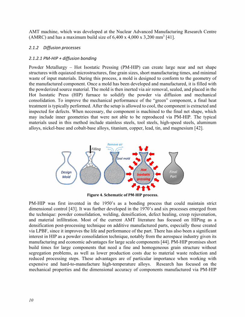
Powder Metallurgy – Hot Isostatic Pressing (PM-HIP) can create large near and net shape structures with equiaxed microstructures, fine grain sizes, short manufacturing times, and minimal waste of input materials. During this process, a mold is designed to conform to the geometry of the manufactured component. Once a mold has been developed and manufactured, it is filled with the powderized source material. The mold is then inerted via air removal, sealed, and placed in the Hot Isostatic Press (HIP) furnace to solidify the powder via diffusion and mechanical consolidation. To improve the mechanical performance of the “green” component, a final heat treatment is typically performed. After the setup is allowed to cool, the component is extracted and inspected for defects. When necessary, the component is machined to the final net shape, which may include inner geometries that were not able to be reproduced via PM-HIP. The typical materials used in this method include stainless steels, tool steels, high-speed steels, aluminum alloys, nickel-base and cobalt-base alloys, titanium, copper, lead, tin, and magnesium [42].
Figure 4. Schematic of PM-HIP process.
PM-HIP was first invented in the 1950’s as a bonding process that could maintain strict dimensional control [43]. It was further developed in the 1970’s and six processes emerged from the technique: powder consolidation, welding, densification, defect healing, creep rejuvenation, and material infiltration. Most of the current AMT literature has focused on HIPing as a densification post-processing technique on additive manufactured parts, especially those created via LPBF, since it improves the life and performance of the part. There has also been a significant interest in HIP as a powder consolidation technique, notably from the aerospace industry given its manufacturing and economic advantages for large scale components [44]. PM-HIP promises short build times for large components that need a fine and homogeneous grain structure without segregation problems, as well as lower production costs due to material waste reduction and reduced processing steps. These advantages are of particular importance when working with expensive and hard-to-manufacture high-temperature alloys. Research has focused on the mechanical properties and the dimensional accuracy of components manufactured via PM-HIP
11
[43], mostly to validate the reliability of the material and the technique itself as a possible alternative for the production of engine and gas turbine vanes [45], [46].
Since the technique has been developed with large-scale components in mind, there are large-scale commercial options available, with the largest current machinery being Kobelco’s HP1450 [47], which has a pressure vessel size of 1,220 mm x 2000 mm (diameter x length), a maximum temperature of 850C, and a maximum pressure of 98 MPa using nitrogen [47]. The largest prototype currently available for PM-HIPing is the Electric Power Research Institute’s (EPRI’s) ATLAS [7], which will have a maximum HIP unit size of 3,100 mm x 5000 mm (diameter x length), a maximum temperature of 1093C, and a maximum pressure of 103 MPa using argon [48]. EPRI has been actively developing PM-HIP as a viable technology for ASME compliant nuclear vessels [49], since PM-HIP can create large components with homogenous material properties that require minimal welding [50].
2.1.2.2 Binder-jetting
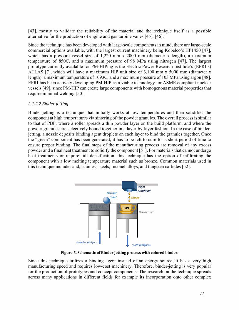
Binder-jetting is a technique that initially works at low temperatures and then solidifies the component at high temperatures via sintering of the powder granules. The overall process is similar to that of PBF, where a roller spreads a thin powder layer on the build platform, and where the powder granules are selectively bound together in a layer-by-layer fashion. In the case of binder-jetting, a nozzle deposits binding agent droplets on each layer to bind the granules together. Once the “green” component has been generated, it has to be left to cure for a short period of time to ensure proper binding. The final steps of the manufacturing process are removal of any excess powder and a final heat treatment to solidify the component [51]. For materials that cannot undergo heat treatments or require full densification, this technique has the option of infiltrating the component with a low melting temperature material such as bronze. Common materials used in this technique include sand, stainless steels, Inconel alloys, and tungsten carbides [52].
Figure 5. Schematic of Binder Jetting process with colored binder.
Since this technique utilizes a binding agent instead of an energy source, it has a very high manufacturing speed and requires low-cost machinery. Therefore, binder-jetting is very popular for the production of prototypes and concept components. The research on the technique spreads across many applications in different fields for example its incorporation onto other complex
12
manufacturing techniques such as sand casting or its use for sensitive materials [51]. Additionally, there is an interest of using binder-jetting as a mass production technique, which is a feature rarely investigated in any other AMT. Key parameters under consideration include the final microstructure generated, the level of densification achieved, and the distribution of the different phases in the final component [52], [53]. Similar to PM-HIP, binder jetting enables the creation of a microstructurally homogeneous material, albeit issues remain with the proper segregation of secondary phases as well as the removal of porosity that may arise from the agglomeration of the binding agent between the powder granules [53], [54].
Given that this technique has mostly been developed for the manufacturing of mid-size prototypes, most commercial machines have a limited build volume size. The largest commercial machine currently available is ExOne’s X1 160PRO, with a maximum build volume of 800 x 500 x 400 mm3, which is roughly a quarter of the volume that other AMTs offer, and a maximum build deposition rate of 10,000 cm3/hour, which is two magnitudes faster than any other AMT currently available [55]. Therefore, this technique shows promising manufacturing speeds at the expense of the component’s size.
2.1.3 Other AMTs
In addition to the five AMTs identified in the Nuclear Energy Institute (NEI) report, cold spray may also be applied to future nuclear systems, either as a means of cladding in new components or a means of repair for existing components.
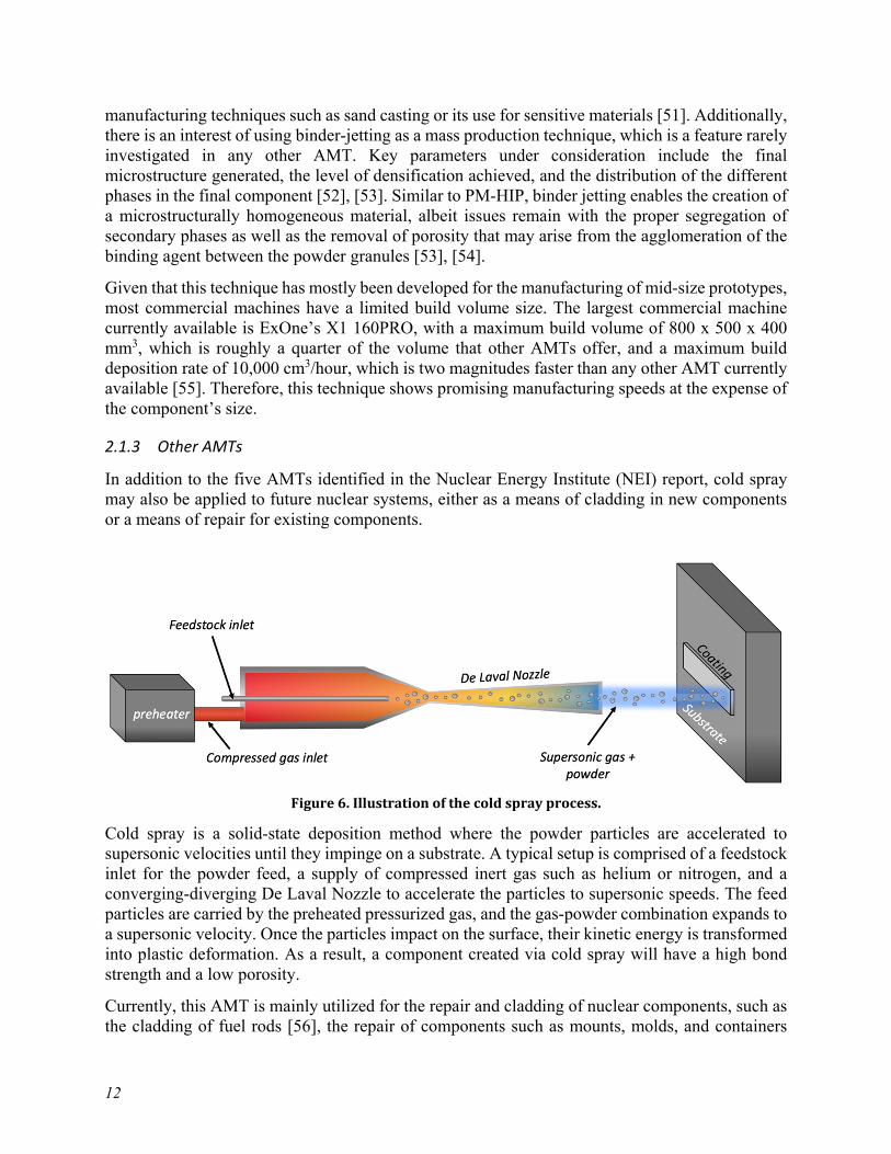
Figure 6. Illustration of the cold spray process.
Cold spray is a solid-state deposition method where the powder particles are accelerated to supersonic velocities until they impinge on a substrate. A typical setup is comprised of a feedstock inlet for the powder feed, a supply of compressed inert gas such as helium or nitrogen, and a converging-diverging De Laval Nozzle to accelerate the particles to supersonic speeds. The feed particles are carried by the preheated pressurized gas, and the gas-powder combination expands to a supersonic velocity. Once the particles impact on the surface, their kinetic energy is transformed into plastic deformation. As a result, a component created via cold spray will have a high bond strength and a low porosity.
Currently, this AMT is mainly utilized for the repair and cladding of nuclear components, such as the cladding of fuel rods [56], the repair of components such as mounts, molds, and containers

13
[56], and the protective coating of nuclear fuel repositories [57]. Cold spray, unlike all other AMTs, presents the advantage of being very flexible to the point that it can be used to repair components on-site, and it does not add thermal deformation on the surrounding material. Furthermore, given that the particles are bonded on the substrate via pure kinetic energy, the manufacturer does not need to worry about material compatibility between the powder and the substrate. One big limitation behind this technique, however, is the lack of geometric control and tolerances on the manufactured component, especially when compared to the laser-based AMTs. As a result, oftentimes the repairs performed by cold spray require some post-processing after the material is deposited to correct the geometry.
2.2 Comparison and Summary
For most of the AMTs discussed in this chapter, a high building speed sacrifices the quality of the component being generated due to the increased porosity, warping, inclusions, and high texturing that is generated in the material at high scan speeds. A notable exception of this tradeoff is the PM-HIP technique, which enables the fast manufacturing of components with great material quality. The issue with PM-HIP is that it is more difficult to implement than other ready-to-use AMTs because it requires a more complicated infrastructure. Aside from PM-HIP, wire-fed EBW is the other AMT that reliably delivers high quality materials at a relatively fast build speed, mainly because the wire used to feed the scan contains almost no defects and it deposits much thicker scan layers than other feeding techniques. If manufacturing speed is what interests the engineer, binder-jetting is the fastest technique of all AMTs and is the reason why it is used for rapid prototyping. However, it comes at the cost of low material quality and a limited build volume. All AMTs, however, have the following gaps: none of them are commonly used for the manufacturing of large components spanning several meters, and all of them produce components with a highly variable material performance that has been difficult to regularize and certify by other industries, especially when compared to the performance of traditionally manufactured materials. Furthermore, the quantity of providers with good manufacturing experience varies wildly by AMT, and it depends heavily on the age and popularity of the AMT. Lastly, even though AMTs have been thoroughly studied by other industries, their AMT research may be concentrated on their own materials of interest (such as titanium and aluminum alloys) and therefore the nuclear community may need to perform further research to address uses and limitations of their own materials.
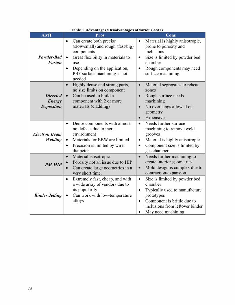
A summary of the advantages and disadvantages of each AMT of interest has been outlined in Table 1.
14
Table 1. Advantages/Disadvantages of various AMTs. AMT Pros Cons
Powder-Bed Fusion
• Can create both precise (slow/small) and rough (fast/big) components
• Great flexibility in materials to use
• Depending on the application, PBF surface machining is not needed
• Material is highly anisotropic, prone to porosity and inclusions
• Size is limited by powder bed chamber
• Rough components may need surface machining.
Directed Energy
Deposition
• Highly dense and strong parts, no size limits on component
• Can be used to build a component with 2 or more materials (cladding)
• Material segregates to reheat zones
• Rough surface needs machining
• No overhangs allowed on geometry
• Expensive.
Electron Beam Welding
• Dense components with almost no defects due to inert environment
• Materials for EBW are limited • Precision is limited by wire
diameter
• Needs further surface machining to remove weld grooves
• Material is highly anisotropic • Component size is limited by
gas chamber
PM-HIP
• Material is isotropic • Porosity not an issue due to HIP • Can create large geometries in a
very short time.
• Needs further machining to create interior geometries
• Mold design is complex due to contraction/expansion.
Binder Jetting
• Extremely fast, cheap, and with a wide array of vendors due to its popularity
• Can work with low-temperature alloys
• Size is limited by powder bed chamber
• Typically used to manufacture prototypes
• Component is brittle due to inclusions from leftover binder
• May need machining.

15
3 Key microstructural characteristics and processing parameters
3.1 Introduction
This chapter describes the basic microstructural characteristics that determine the material properties and part quality for the AMTs covered in this report. Predicting these microstructural characteristics is the fundamental goal of any process model, as they could in turn be used to predict the material properties and other characteristics that determine the quality and performance of the final component. The final microstructure of a component is dictated by a set of key processing parameters – a generally configurable set of parameters that control how the component is produced. Examples of processing parameters for AMTs include laser power, beam speed, ambient temperature and pressure, process atmosphere, and many others [58]–[62]. Once these key microstructural characteristics and the corresponding controlling processing parameters are identified, process models can be developed that relate the processing parameters to the final produced microstructures.
Figure 7. Grain morphology of DED of TC18 titanium alloy with different morphologies given changing
processing parameters. Taken from [30].
As described in previous chapters, this report divides the AMTs of interest into two broad categories: methods based on fusion, that is local melting and resolidification, and methods based on diffusion and/or mechanical deformation. Previous classification schemes likewise adopt this taxonomy (and additionally include mechanical joining processes as a third category, not relevant to the AMTs considered here [3]). This chapter reflects this division. However, the picture is complicated by post-processing of AMT components. For example, a component manufactured via powder bed fusion (a fusion process) might then be post-processed using hot isostatic process (a deformation/diffusion process). Furthermore, some broad categories of process models are applicable across many AMTs – for example, melt pool solidification models are applicable to laser and electron beam based PBF, DED, and welding processes. As such, this report is based

16
around modular process models representing key processes common to several AMTs. A complete process model for a particular technology would combine the appropriate modular processing models to predict the final material structure. However, with some exceptions discussed in later chapters, the state of the art is not yet developed to the point where such comprehensive process models are available. As such, this chapter is an important key to the rest of the report, in that it is a way to relate the individual process models described in subsequent chapters to the AMTs discussed in this report.
3.2 Microstructural characteristics of interest
3.2.1 Overview
One way to identify key processing parameters is to first identify the characteristics of interest in the final material and then link those characteristics to the processing parameters controlling their development. This section makes these connections. However, the discussion of key microstructural characteristics determining the final material properties is deliberately kept brief as this topic will be a key part of a future report on methods for predicting material properties from microstructural characteristics.
3.2.2 Grain size, shape, morphology, and texture
The grain size, shape, morphology, and texture are all key characteristics determining the final strength, ductility, and failure properties of the final material [63]. Relevant characteristics include average grain size, grain morphology (for example columnar versus equiaxed dendritic shapes for fusion processes), aspect ratios for non-equiaxed grain structures, and measurements of texture.
Figure 8. Main grain characteristics affecting material properties

17
Key processing characteristics influencing grain morphology and texture include deposition rates [64], beam energy on target (beam power, focus, scan strategy, and speed) [65]–[68], melt pool dimensions [69], powder bed preheat [70], and postprocessing regimen [71].
3.2.3 Void shape, size, and distribution
Porosity in the final material structure significantly affects the fatigue resistance of the final component [72]–[76]. Very high levels of porosity can negatively affect other mechanical properties. Typical experimental measurements of porosity include relative density measurement as well as x-ray tomography, which can determine pore size and shape distributions. Post-processing, like HIP, can be used to reduce or eliminate porosity in AM-produced parts. These post-processing techniques have their own set of key processing variables, some of which are discussed below in 3.3.2 in relation to diffusional AMTs like PM-HIP.
3.2.4 Precipitate structure and phase distribution
The phase structure of the material significantly contributes to material strength and damage resistance, especially for precipitate strengthened alloys [77], [78]. Conversely, phase segregation can negatively affect the performance of solution strengthened materials [79]–[81]. Oxides, potentially developed through oxidation of the metal powder during melting/sintering, included in the final material structure are prime locations for void nucleation, leading to reduced fatigue resistance [82].
3.2.5 Residual stress and distortion
Most fusion-based AMTs will induce some degree of residual stress and/or distortion in the final component. As described in detail below in 4.1, both residual stress and build distortion are caused by fundamentally the same differential cooling mechanism, the difference being the degree of mechanical constraint provided by build substrate or rest of the completed build. Mechanistically, residual stresses are caused by gradients in the dislocation structure of the solidified material. If controlled, beneficial residual stresses can increase fatigue life [83]. However, large residual stresses can reduce the mechanical performance of the final component and even cause premature build failure [84]. Various build strategies [85] and postprocessing heat treatments can be used to reduce or eliminate residual stress in final components [86].
3.2.6 Surface roughness and finish
Surface roughness is a key material characteristic influencing fatigue strength. Oftentimes parts produced with AMTs have significantly worse surface finish than conventionally machined components [87] and so improving surface roughness of AM-produced materials has been a major research topic. Surface finish can be improved using a variety of post-processing techniques [88]–[90], each in turn controlled by its own set of key processing variables.
3.3 Key processing parameters
3.3.1 Fusion processes
The following section describes the processes and corresponding parameters that determine the final microstructure of materials processed via fusion techniques. For this report, these techniques
18
include powder bed fusion, directed energy deposition, and electron beam welding. Traditional welding techniques also rely on fusion processes, and so a brief survey of the literature on conventional weld process modeling is included. However, the focus of the report is on the particular AMTs of interest.
3.3.1.1 Overview: melt pool solidification
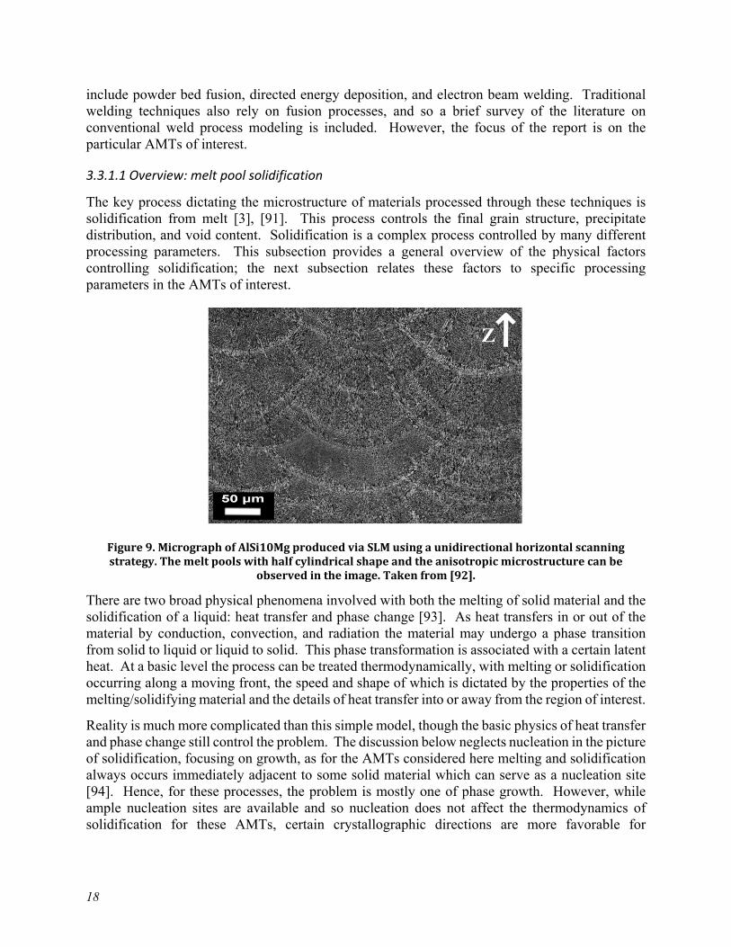
The key process dictating the microstructure of materials processed through these techniques is solidification from melt [3], [91]. This process controls the final grain structure, precipitate distribution, and void content. Solidification is a complex process controlled by many different processing parameters. This subsection provides a general overview of the physical factors controlling solidification; the next subsection relates these factors to specific processing parameters in the AMTs of interest.
Figure 9. Micrograph of AlSi10Mg produced via SLM using a unidirectional horizontal scanning strategy. The melt pools with half cylindrical shape and the anisotropic microstructure can be
observed in the image. Taken from [92].
There are two broad physical phenomena involved with both the melting of solid material and the solidification of a liquid: heat transfer and phase change [93]. As heat transfers in or out of the material by conduction, convection, and radiation the material may undergo a phase transition from solid to liquid or liquid to solid. This phase transformation is associated with a certain latent heat. At a basic level the process can be treated thermodynamically, with melting or solidification occurring along a moving front, the speed and shape of which is dictated by the properties of the melting/solidifying material and the details of heat transfer into or away from the region of interest.
Reality is much more complicated than this simple model, though the basic physics of heat transfer and phase change still control the problem. The discussion below neglects nucleation in the picture of solidification, focusing on growth, as for the AMTs considered here melting and solidification always occurs immediately adjacent to some solid material which can serve as a nucleation site [94]. Hence, for these processes, the problem is mostly one of phase growth. However, while ample nucleation sites are available and so nucleation does not affect the thermodynamics of solidification for these AMTs, certain crystallographic directions are more favorable for
19
solidification than others [51]. This means the underlying crystal structure can affect the type of grain structure and the directionality of grain growth.
Except at very slow, controlled cooling rates metallic materials will form polycrystal structures when solidified from melt. The grain structure resulting from this phase growth determines many of the microstructural characteristics of interest noted above. The type of grain structure formed in the cooling process is controlled by the temperature gradient and the solidification rate [51]. The factors controlling these two key parameters are discussed below for the AMTs of interest. Most commonly, AMTs produce either equiaxed (no texturing) dendritic microstructures or columnar (heavy texturing) dendritic microstructures, depending on the temperature gradient and solidification rate.
Grain growth typically occurs along the machine z-direction, directly away from the build surface, for PBF processes and/or very fast scan speeds [95]–[97]. Slower scan speeds and DED processes can produce non-vertical columnar grains [98]–[100] where the direction of grain growth may be affected by the crystallography of the underlying material.
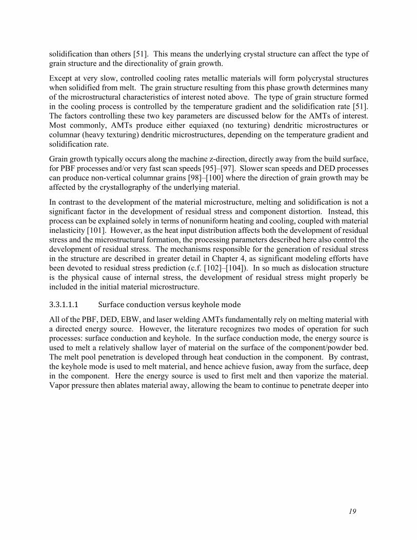
In contrast to the development of the material microstructure, melting and solidification is not a significant factor in the development of residual stress and component distortion. Instead, this process can be explained solely in terms of nonuniform heating and cooling, coupled with material inelasticity [101]. However, as the heat input distribution affects both the development of residual stress and the microstructural formation, the processing parameters described here also control the development of residual stress. The mechanisms responsible for the generation of residual stress in the structure are described in greater detail in Chapter 4, as significant modeling efforts have been devoted to residual stress prediction (c.f. [102]–[104]). In so much as dislocation structure is the physical cause of internal stress, the development of residual stress might properly be included in the initial material microstructure. 3.3.1.1.1 Surface conduction versus keyhole mode All of the PBF, DED, EBW, and laser welding AMTs fundamentally rely on melting material with a directed energy source. However, the literature recognizes two modes of operation for such processes: surface conduction and keyhole. In the surface conduction mode, the energy source is used to melt a relatively shallow layer of material on the surface of the component/powder bed. The melt pool penetration is developed through heat conduction in the component. By contrast, the keyhole mode is used to melt material, and hence achieve fusion, away from the surface, deep in the component. Here the energy source is used to first melt and then vaporize the material. Vapor pressure then ablates material away, allowing the beam to continue to penetrate deeper into
20
the component by creating a tunnel or “keyhole”. As the beam moves away melted material flows into the keyhole, solidifies, and creates the solid bond.
Figure 10. Schematic of surface conduction and keyhole mode
EBW and laser welding can be performed in either conduction or keyhole mode [91]. The mode selection depends on the component geometry, depth of the desired weld, and other factors. Typically, the PBF and DED additive processes operate in conduction mode, though some evidence suggests keyholing may occur during these processes as well [105], [106].
The beam power and speed largely dictate which mode the process operates in [107], [108]. These same factors control the heating and cooling rates and melt pool geometry, and so are discussed in greater detail below.
3.3.1.2 General parameters The following parameters apply to all fusion processes. Subsequent sections describe parameters specific to PBF, DED, and e-beam welding techniques. 3.3.1.2.1 Heat transfer Heat transfer into and through the component controls many of the key parameters in fusion-based processes. All three standard forms of heat transfer occur during these processes: radiation, convection, and conduction. There is evidence [51] suggesting that neglecting any of these three modes of heat transfer can lead to inaccurate predictions of final material properties and hence all three significantly contribute in the actual AMT processes. 3.3.1.2.2 Energy source power and speed The first key set of parameters controlling fusion processes are the power and speed of the energy source. All of the AMTs of interest for this report use directed energy beams to melt material. The combination of the beam speed and power dictates the melt pool geometry and strongly

21
influences the critical solidification rate and temperature gradient at the edge of the melt pool, which in turn dictate the final grain structure. These two parameters control the heat input to the component/build volume and hence strongly influence local melting and resolidification [109].
However, additional characteristics of the energy source also affect heat transfer and melt characteristics in the component. The beam focus, which can be controlled by optical lenses for laser source and magnetic lenses for electron beam sources, determines the distribution of input power at the surface of the component and can affect melt pool geometry and the final material microstructure [110].
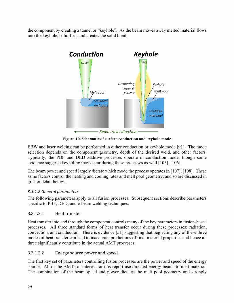
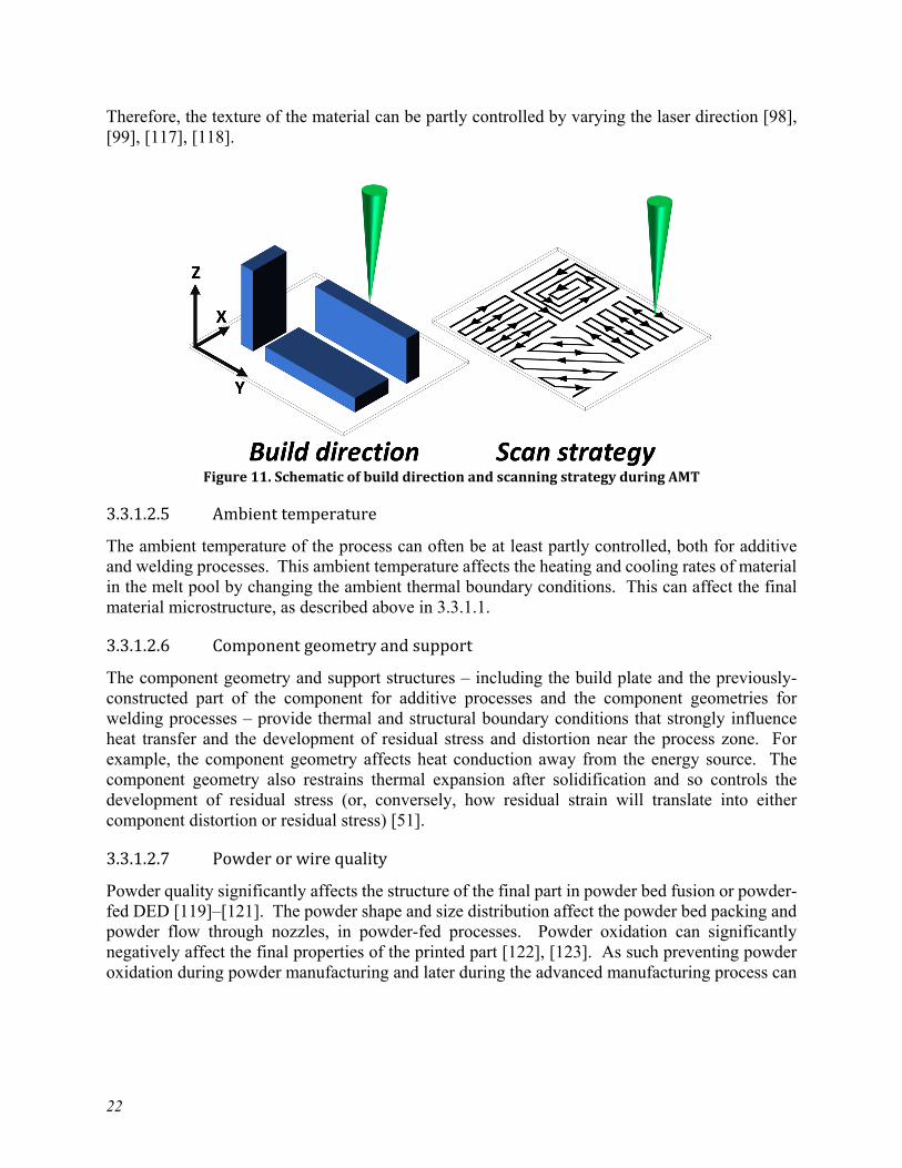
The input energy to the surface of the component also controls whether the process proceeds in surface or keyhole mode. Keyholing can be undesirable in the PBF and DED additive processes as it can lead to internal porosity [106], while it may be desirable for EBW since the keyhole mode enables a deep penetration weld [111], as seen in Figure 10. Additionally, for some materials vaporization of certain components of the base metal alloy, as opposed to complete vaporization of the entire metal as in keyholing, may selectively remove some elements from the melt, leading to degraded final material properties [112]. 3.3.1.2.3 Underlying material properties The second key set of parameters controlling the melt pool geometry and material solidification rates are the material properties of the underlying base material. The critical material properties include the material thermal conductivity, thermal diffusivity, and liquid state viscosity and surface tension [109]. For thermal properties it is the effective properties of the build surface or powder bed, as appropriate, that are most relevant and not simply the base material properties. 3.3.1.2.4 Build direction/scan strategy The melt pool width is typically much smaller than the width of features in the final component. As such a hatching/scanning strategy is used to raster the energy source over the build surface to build up the required component thickness. Similarly, in welding processes a scanning strategy is often used to increase the thickness of the fusion zone or to blend two dissimilar materials that would otherwise resist mixing. The details of this scanning strategy affect the heat input to the component and hence the properties of the final part [113], [114].
A related issue is heat transfer from subsequent layers in additive processes. These techniques build up the component one layer at a time. Heat from subsequent layers, depending on the beam characteristics and layer thickness, may transfer into the previous layers. In extreme cases this may cause remelting of those earlier layers, which affects the final material microstructure [115], [116].
Additionally, the direction of travel of the beam can also dictate the texture of the final material. Many processes tend to produce a fiber texture in the direction of travel of the energy source.
22
Therefore, the texture of the material can be partly controlled by varying the laser direction [98], [99], [117], [118].
Figure 11. Schematic of build direction and scanning strategy during AMT 3.3.1.2.5 Ambient temperature The ambient temperature of the process can often be at least partly controlled, both for additive and welding processes. This ambient temperature affects the heating and cooling rates of material in the melt pool by changing the ambient thermal boundary conditions. This can affect the final material microstructure, as described above in 3.3.1.1. 3.3.1.2.6 Component geometry and support The component geometry and support structures – including the build plate and the previously-constructed part of the component for additive processes and the component geometries for welding processes – provide thermal and structural boundary conditions that strongly influence heat transfer and the development of residual stress and distortion near the process zone. For example, the component geometry affects heat conduction away from the energy source. The component geometry also restrains thermal expansion after solidification and so controls the development of residual stress (or, conversely, how residual strain will translate into either component distortion or residual stress) [51]. 3.3.1.2.7 Powder or wire quality Powder quality significantly affects the structure of the final part in powder bed fusion or powder-fed DED [119]–[121]. The powder shape and size distribution affect the powder bed packing and powder flow through nozzles, in powder-fed processes. Powder oxidation can significantly negatively affect the final properties of the printed part [122], [123]. As such preventing powder oxidation during powder manufacturing and later during the advanced manufacturing process can

23
be crucial in achieving the correct microstructure. This problem is especially acute for materials that oxidize easily in the bulk form (e.g. Ti-alloys, refractories, etc.) and for very fine powder sizes.
A great deal of research has been devoted to powder reuse [124]–[127]. During manufacturing various processes cause powder oxidation and partial fusion. This negatively affects the powder quality if the same powder is then reused for a second build. These effects can be partially ameliorated by sieving and other post-manufacturing processes.
3.3.1.3 Parameters specific to powder bed fusion processes 3.3.1.3.1 Powder-bed packing The powder bed packing and general quality of the powder affects the effective thermal properties of the powder bed – critical for predicting heat transfer – and influences the development of internal porosity [128], [129]. Typically, spherical powders with uniform size distributions are preferred. Reuse of powder strongly affects both the size and shape of the powder in the next build and so can significantly affect the final material microstructure [124].
Powder flowability is a concern during the scraping process when the powder bed is releveled. However, here the concern is typically damage to the scraper and a corresponding non-leveled powder bed caused by the accumulation of material. 3.3.1.3.2 Layer thickness The powder layer thickness affects heat transfer and remelting during manufacturing [130]. Additionally, the layer thickness affects the final surface finish of the component as it sets the characteristic length scale for the stair stepping effect generated by the layer-by-layer AMT [131].
3.3.1.4 Parameters specific to directed energy deposition processes 3.3.1.4.1 Powder flowability For powder-fed DED processes the powder size and shape distribution affects the flowability of the powder through the feeder nozzles [132]. Poor nozzle flow can lead to poor quality final parts by causing lack-of-fusion defects and porosity in the component. 3.3.1.4.2 Wire quality For wire-fed processes the filler wire quality can affect the build. For example, larger diameter filler wires lead to larger melt pool sizes, which in turn limits the resolution of the printing process [133].
3.3.1.5 Parameters specific to laser heat sources 3.3.1.5.1 Material absorptivity The actual heat flux delivered to the component/powder bed is controlled both by the laser power and by the absorptivity of the base material [134], [135]. As such, base material absorptivity is a critical processing parameter. The effective absorptivity of the material can be affected by vapor from the melt region, the process atmosphere, and changes to the optical characteristics of the
24
component/powder bed caused by previous passes. Depending on the process, all of these characteristics may be significant processing variables. 3.3.1.5.2 Atmosphere Typically, laser fusion processes are conducted in an inert atmosphere, often argon gas. This is to avoid oxidation and other chemical reactions that may occur during the melting process. The gas quality is therefore a potentially important process variable. If the AMT does not deliver a pure, inert atmosphere at the point of melting this may cause the development of material impurities in the final part and affect the absorptivity of the material during the manufacturing process [136].
3.3.1.6 Parameters specific to electron beam heat sources 3.3.1.6.1 Material (electrical) conductivity The amount of heat generated by an electron beam depends on the electrical conductivity of the base material [137]. For powder-bed processes the effective conductivity of the powder-bed is the property of interest and in all cases defects caused by lack of fusion or porosity developed during the process can change the effective conductivity of the base material. 3.3.1.6.2 Vacuum quality Electron beam processes are typically conducted in a vacuum to avoid energy losses caused by premature interaction between the electron beam and the atmosphere. Furthermore, the vacuum prevents electrical arcing and help eliminate chemical reactions like oxidation on the build surface. Therefore, vacuum quality is a significant processing variable for electron-beam technologies [137].
3.3.1.7 Postprocessing
Subsequent to building the component it can be removed from the AMT machine and some postprocessing step applied to improve the engineering properties of the final component. These postprocessing techniques in turn are controlled by their own extensive set of processing variables. A brief overview is provided here. 3.3.1.7.1 Heat treatment

25
Post-manufacture heat treatment of AMT components falls into three categories.
1. Residual stress relief
2. Solution anneal/age hardening
3. Full recrystallization
Figure 12. Overview of the three heat treatment categories
Temperatures increase from #1 to #3, though the particular temperature required to achieve the intended objective depends on the material type and, to some extent, the prior manufacturing process. The goal of a residual stress relief heat treatment is to remove internal residual stresses introduced by the manufacturing process. The physical mechanism here is static recovery of dislocation structure. Solution anneals and age hardening both aim to rearrange the distribution of second-phase precipitates in the material. Solution annealing aims to place second phase precipitates into solution; age hardening aims to take them out of solution. The specific objectives and required temperature histories for these processes are highly material dependent [138]. Post-weld heat treatment for EBW [139]–[142] falls into this category (along with stress relief), in addition to classical bulk solution annealing of AMT components. Finally, a full recrystallization (i.e. a full anneal) heat treatment actually alters the grain structure of the base alloy solution. The mechanisms operating in the material for these three types of heat treatments are discussed below in 3.3.2.
As many of the AMT, including laser and ebeam powder bed fusion, use configurable heat sources many of these heat treatments can take place in-situ in the manufacturing device, rather than relying on ex-situ post-construction heat treatments [143], [144]. For machines with multiple laser or ebeam heat sources, one beam could be used to melt material while the second used to follow up the main melt/resolidification to provide a heat treatment. Both in-situ and ex-situ heat treatments have been developed specifically for AMT materials, as opposed to relying on heat treatment regimens developed for conventional wrought or cast material [145]–[148].
More exotic post-processing treatments have been considered or applied to AMTs. Examples include in-situ cold work applied through a robotically controlled roller [149], [150] and laser peening, either in post-manufacturing or using the machine heat source [151], [152]. The
26
mechanism for these approaches is cold work increasing the material dislocation density. While they have merit for particular manufacturing processes and materials [1], they are not yet widely adopted and so not discussed in detail here. 3.3.1.7.2 HIP Hot isostatic pressing can be used as a post-processing technique on material manufactured via a fusion process. Typically, the objective is the removal of internal porosity, though the HIP treatment may also improve basic mechanical properties [153]–[157]. A complete discussion of the HIP processes is provided below in 3.3.2. 3.3.1.7.3 Machining and etching Surface finish in AMT components is often poor and can be improved by post-manufacturing machining [153], [158], [159]. Even for ebeam or laser welding smoothing the weld surface by post-weld grinding often improves creep and fatigue life [160]. Additionally, chemical etching has been considered as a post-manufacturing process to reduce surface roughness, particularly for very fine components like lattice structures [161]. Each of these processes has its attendant processing variables. This report does not focus on these methods as they are not unique to AMTs.
3.3.2 Diffusional processes
This section details the processing parameters controlling the microstructure of components processed using either conventional sintering or hot isostatic pressing (HIP). These technologies can be used to produce components directly (as in PM-HIP), to post-process components manufactured using other AMTs, or, in the case of binder jet technologies, in a combination of both tasks, as sintering or HIPing is used to densify and remove the binder from premanufactured green parts.
3.3.2.1 Overview: diffusion, pore collapse, and recrystallization
In both HIPing and sintering diffusional pore reduction, pore collapse, and recrystallization can all play a role [162]. However, in conventional sintering diffusional pore reduction and recrystallization are the dominant mechanisms, while the HIP process always involves pore collapse but may also include diffusional pore reduction and recrystallization, depending on the processing parameters. As the HIP process in particular can include all three mechanisms, they are described in common in this section.
The driving force for diffusional pore reduction is surface energy [162], [163]. Thermodynamics drive a material towards the lowest possible energy state. Removing a surface reduces the energy of an otherwise perfect atomic lattice, and so reducing the surface area contained in a volume of
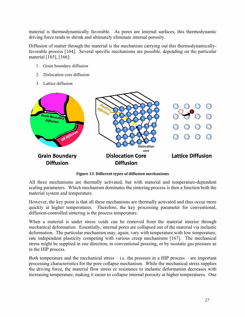
27
material is thermodynamically favorable. As pores are internal surfaces, this thermodynamic driving force tends to shrink and ultimately eliminate internal porosity.
Diffusion of matter through the material is the mechanism carrying out this thermodynamically-favorable process [164]. Several specific mechanisms are possible, depending on the particular material [165], [166]:
1. Grain boundary diffusion
2. Dislocation core diffusion
3. Lattice diffusion
Figure 13. Different types of diffusion mechanisms
All three mechanisms are thermally activated, but with material and temperature-dependent scaling parameters. Which mechanism dominates the sintering process is then a function both the material system and temperature.
However, the key point is that all these mechanisms are thermally activated and thus occur more quickly at higher temperatures. Therefore, the key processing parameter for conventional, diffusion-controlled sintering is the process temperature.
When a material is under stress voids can be removed from the material interior through mechanical deformation. Essentially, internal pores are collapsed out of the material via inelastic deformation. The particular mechanism may, again, vary with temperature with low temperature, rate independent plasticity competing with various creep mechanisms [167]. The mechanical stress might be supplied in one direction, in conventional pressing, or by isostatic gas pressure as in the HIP process.
Both temperature and the mechanical stress – i.e. the pressure in a HIP process – are important processing characteristics for the pore collapse mechanism. While the mechanical stress supplies the driving force, the material flow stress or resistance to inelastic deformation decreases with increasing temperature, making it easier to collapse internal porosity at higher temperatures. One
28
advantage of the HIP process is that it can achieve full consolidation at lower temperatures than conventional sintering through this combination of temperature and mechanical stress [168]
Finally, both temperature and pressure contribute to recrystallization [169]. Recrystallization can be thought of in terms of thermodynamics, as with diffusional pore reduction. Grain boundaries are defects in an otherwise perfect atomic lattice, and so reducing the area of grain boundaries contained in a material is energetically favorable. Again, the mechanisms controlling the process are thermally activated and so recrystallization occurs more rapidly at higher temperatures. The process of recrystallization tends to increase the average grain size by removing grain boundary surface. Often, this grain growth is unwanted. One of the advantages of HIP processes is that they can remove internal porosity at lower temperatures than conventional sintering, thus minimizing the amount of grain growth that occurs along with the densification process [170].
The literature describes two types of recrystallization – static recrystallization and dynamic recrystallization [171]. Static recrystallization occurs under zero mechanical load simply through thermal activation, whereas stress contributes a driving force in dynamic recrystallization [172], [173]. Static recrystallization is then present in both classical sintering and HIP processes, whereas dynamic recrystallization is present only in the HIP process.
Dislocations are similarly a defect in an otherwise perfect crystal, and so again time at elevated temperature will tend to reduce the dislocation density in a material [174]. This process of static dislocation recovery contributes to the final material structure and the resulting material properties. Residual stress can be expressed in terms of the dislocation structure of a material and so stress relief heat treatments are a controlled by static recovery processes. Like grain recrystallization, dislocation density can also be reduced via dynamic recovery controlled by stress. Dynamic recovery is at best a secondary mechanism in HIP processes, and so this report does not cover process models for this mechanism.
A third, relatively new solidification process might be included along with classical sintering and HIP: Field Assisted Sintering Technique (FAST) otherwise known as Spark Plasma Sintering (SPS) [175]. This method has been used and/or proposed for use in sintering parts produced using traditional powder metallurgy and for use in densifying green parts produced using binder jet processes [176]–[179]. One advantage of this technique over classical sintering and HIP is that it achieves much higher temperatures and faster heating/cooling rates, enabling the densification of materials with very high melting points like ceramics [180]–[182].
The basic FAST process involves placing a green part contained in a conductive (often graphite) die in a conductive mechanical pressing fixture. Force is then applied to the specimen, either through the fixture or with gas pressure. In either case, the process often takes place in an inert atmosphere. A high electrical current then passes through fixture, causing rapid heating in the part either through direct Joule heating of the green part, if it is sufficiently conductive, or via conduction from Joule heating occurring in the press fixture. Very high temperatures and rapid heating and cooling rates are achievable, up to 2400° C and 1000° C/min [175].
The consolidation mechanisms underlying the FAST process are still not well understood. The three mechanisms mentioned above – diffusional pore reduction, pore collapse, and recrystallization – are active, or can be active depending on the processing parameters. However, the electrical field itself contributes to consolidation through at least two distinct mechanisms [183], [184]. While FAST is likely to compete with traditional sintering and HIP in the future,

29
this report does not discuss the processing parameters related to the electrical field directly, instead limiting the discussion to the more general parameters of temperature and pressure.
3.3.2.2 General parameters
These parameters affect consolidation and recrystallization for both HIP and classical sintering and apply equally to binder jet and traditional powder metallurgy green parts. 3.3.2.2.1 Temperature The part temperature is dominant processing parameter for this broad category of consolidation mechanisms [162]. As discussed in 3.3.2.1, temperature controls diffusion and static crystallization and affects pore collapse mechanisms by reducing the material flow stress. Temperature controls the rate of all three thermally activated mechanisms and so also controls the relative proportion of grain growth to pore consolidation. Typically, these mechanisms can be ranked in terms of the homologous temperature, and so the melting point of the material versus the available process temperature dictates the possible range of final grain structures.
Oftentimes, the literature discusses mechanisms for constant, isothermal temperature conditions. However, evidence suggests that the transient, non-isothermal portion of the process contains a significant fraction of the consolidation and recrystallization occurring in the part [162], [185]. This suggests that the heating and cooling rates, along with the thermal conductivity and diffusivity of the green and partially-consolidate parts, are important processing parameters. This may be particular true for FAST processes which typically, as the acronym suggests, occur quickly and thus may have higher proportions of transient thermal conditions to steady state conditions when compared to HIP and traditional sintering. 3.3.2.2.2 Pressure The local mechanical stress state, along with the local temperature, controls the rate of mechanical consolidation caused by pore collapse mechanisms [162]. In general, then, pressure is the key process variable controlling this mechanism. However, the component geometry, including the internal porosity and the evolution of porosity with time, controls the actual local mechanical stress state in a part particularly in the case of an anisotropic material or in the presence of friction with the die walls or can coating. Therefore, the part geometry and, in the case of classical pressing process, the die geometry additionally affects the rate of consolidation. 3.3.2.2.3 Time While temperature and pressure set the rates of the various consolidation, recrystallization, and recovery processes the amount of time held at these conditions determines the actual final microstructure [162]. Time is then a key processing parameter for these consolidation mechanisms, as, for example, the rate of recrystallization and consolidation can be set so that very little recrystallization occurs during the process relative to consolidation, simply because the rate of consolidation is much higher than the rate of recrystallization. Time then can often be used to
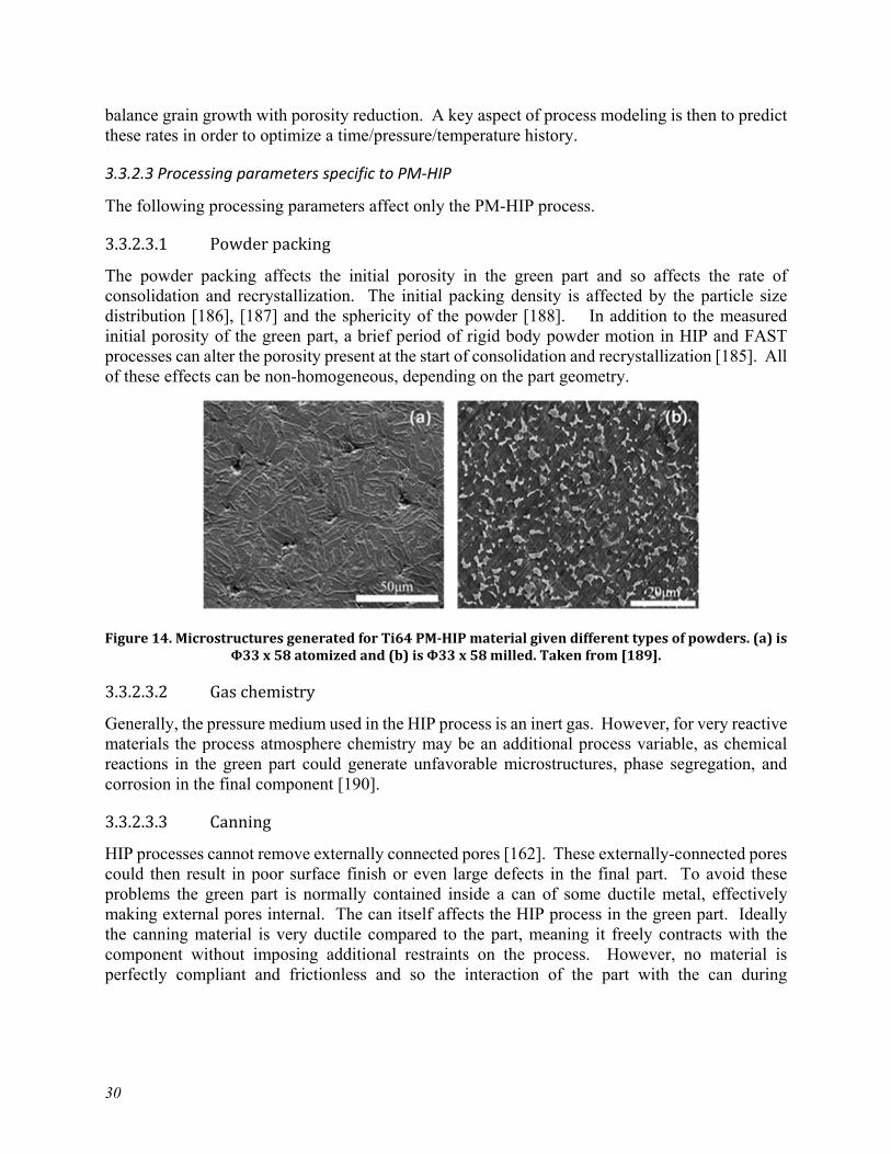
30
balance grain growth with porosity reduction. A key aspect of process modeling is then to predict these rates in order to optimize a time/pressure/temperature history.
3.3.2.3 Processing parameters specific to PM-HIP
The following processing parameters affect only the PM-HIP process. 3.3.2.3.1 Powder packing The powder packing affects the initial porosity in the green part and so affects the rate of consolidation and recrystallization. The initial packing density is affected by the particle size distribution [186], [187] and the sphericity of the powder [188]. In addition to the measured initial porosity of the green part, a brief period of rigid body powder motion in HIP and FAST processes can alter the porosity present at the start of consolidation and recrystallization [185]. All of these effects can be non-homogeneous, depending on the part geometry.
Figure 14. Microstructures generated for Ti64 PM-HIP material given different types of powders. (a) is
Φ33 x 58 atomized and (b) is Φ33 x 58 milled. Taken from [189]. 3.3.2.3.2 Gas chemistry Generally, the pressure medium used in the HIP process is an inert gas. However, for very reactive materials the process atmosphere chemistry may be an additional process variable, as chemical reactions in the green part could generate unfavorable microstructures, phase segregation, and corrosion in the final component [190]. 3.3.2.3.3 Canning HIP processes cannot remove externally connected pores [162]. These externally-connected pores could then result in poor surface finish or even large defects in the final part. To avoid these problems the green part is normally contained inside a can of some ductile metal, effectively making external pores internal. The can itself affects the HIP process in the green part. Ideally the canning material is very ductile compared to the part, meaning it freely contracts with the component without imposing additional restraints on the process. However, no material is perfectly compliant and frictionless and so the interaction of the part with the can during
31
consolidation affects the process. Therefore, the can material properties can be secondary processing variables.
3.3.2.4 Processing parameters specific to binder jet
The following processing parameters are specific to binder jet AMTs followed by conventional sintering. 3.3.2.4.1 Powder quality While powder quality may not significantly affect the manufacture of the green part using the binder jet process, it does affect the final sintering of the component by influencing the initial porosity. Considerations are similar to the HIP process, discussed above in 3.3.2.3.1, with the additional complications caused by the presence of the binding agent. 3.3.2.4.2 Binder removal and residue Typically, a debinding heat treatment precedes the full sintering used to densify the base powder. However, if this preliminary heat treatment does not fully remove the binder the residual binder can affect the sintering of the brown part. Binder additives may be used to promote sintering and residual binder may negatively affect sintering densification. The binder chemistry affects the burn up phase of the sintering post-treatment. Binder chemistry is then an additional process variable to consider for this AMT [191]–[193].
3.4 Summary and Recommendations
This chapter summarized the key processing parameters and resulting microstructural features for the AMTs of interest. One key theme is the wide variety of user-configurable processing parameters. Not only do the key processing parameters vary between the general categories of AMTs discussed here, the specifics of controlling each parameter varies based with the machine manufacturer. Modeling and simulation tools for predicting initial microstructures will need to represent at least a large subset of these key parameters in order to make accurate predictions. Verification and validation for simulation tools must ensure that the method can account for the effects of each processing parameter individually as well as the net aggregate effect of processing parameters applied in combination. In contrast to traditional wrought and cast production methods, AMTs have a richer set of controllable parameters meaning accurate simulation methods may need to incorporate additional physics. The next chapter describes this in greater detail.
AMT materials often have different microstructures than conventionally-processed wrought or cast equivalents. In some cases, these microstructures could be categorized as more complicated than the conventional material – for example the complex grain morphology developed through extremely rapid heating/solidification. Regardless, existing processing simulation tools may not be capable of accurately predicting microstructures from AMT processes. Careful verification and validation will be required, in addition to the development of new simulation techniques.


33
4 Physics-based prediction methods
4.1 Predicting residual stress and distortion Most components have an inherent amount of residual stress and distortion due to their manufacturing and assembly history. In the case of AMTs, the main source of residual stresses and distortions are the large thermal gradients that the energy source unevenly generates throughout the material due to rapid heating and cooling of the material [194]. As a result, many components manufactured through AMTs undergo either pre-processing techniques aimed to lessen the thermal gradients, or post-processing treatments that lower the dislocation density and thus reduce the residual stresses in the material. Lowering the stresses in the material not only prevents the geometry from distorting beyond the design tolerances, but also inhibits premature failure from localized stresses. As a result, there have been significant efforts in modeling the mechanical response in AMT components due to thermal stress. There are two main benefits in using modeling tools: predicting the evolution of stress and deformation can prevent component failures and the simulation of AMTs can be used to optimize the manufacturing process itself [195].
4.1.1 General overview of AMT modeling
4.1.1.1 Thermomechanical modeling Most simulation efforts follow the practices developed by the welding community where the FEA approach is used to perform a nonlinear thermomechanical analysis that can capture the mechanical deformations that arise from the large thermal gradients [195], [196]. During a thermomechanical simulation, a thermal analysis is done first to obtain the temperatures at each node, and then the resulting thermal gradients are used to calculate a mechanical response in the component. If the geometry is updated in every increment of the simulation as the thermal gradients are applied, then the thermomechanical analysis is coupled. If, on the other hand, the mechanical analysis is done after the entire thermal analysis is completed then the thermomechanical analysis is decoupled. Both types of analysis have its advantages and disadvantages: the coupled analysis yields more precise results, whereas the decoupled analysis yields results that are about 4x faster than the fully coupled analysis [197]. In general, the AMT community tends to favor the decoupled thermomechanical analysis since the loss of precision is minor when compared to the uncertainties that arise from other parts of the process.
Figure 15. Schematic of a thermomechanical model. The calculated thermal gradients from the AMT
are implemented onto a mechanical model to obtain residual stresses and deformation
34
4.1.1.2 Representing residual strain 4.1.1.2.1 Inherent strain method To achieve a faster prediction of stresses compared to full thermomechanical analyses alternatives have been devised for large AMT components. One of these methods is the inherent strain method, in which it is assumed that the source of residual stresses is the so-called inherent strain. In this method the residual stresses are predicted from an elastic analysis where the inherent strain is replaced with equivalent distributed loads [198]. These distributed loads in turn can be calculated from an initial thermal-elastic-plastic FEA model that calculates inherent deformations [199], or simply measured directly from the component [200]. For fairly simple AMT processes with basic geometries, this method is fast and capable of predicting residual stresses in large geometries [199], [201]. This method has been successfully applied to PBF components where the inherent strain method was capable of determining the pre-deformed geometry required to compensate for the distortion induced in the AMT process [202]. One of the biggest drawbacks of this technique is that it cannot account for different scan paths nor it can predict the stresses that arise from geometric features [203]. This is because the inherent strain is considered to be constant across the entire volume. A modified method sections the geometry into layers in order to simulate accumulation of the residual deformation [204]. While this approach improves the predictive ability of the inherent strain method, it still can only be used for fairly simple AMT processes. 4.1.1.2.2 Applied plastic strain method Similar to the inherent strain method, the applied plastic strain method, also known as plasticity-based distortion analysis, assumes that there is a relationship between cumulative plastic strains and angular distortions, where the shear plastic strain is the main contributor [205]. This method allows the mapping of plastic strains, obtained from simple 2D analysis, onto full 3D FEA models, thus saving a significant amount of computational time while allowing the model to predict important mechanisms like buckling, bending, and angular deformation [206]. While this method, unlike the inherent strain method, predicts localized stresses in the geometry and complex behaviors like angular deformation, it still has the same disadvantage of not being applicable for complicated AMT components due to the complex plastic strains that arise from the AMT process.
4.1.1.3 Two-step numerical analysis
Methods for mapping information from a simple model onto a more complex model have also been applied to thermomechanical analyses. In the two-step numerical analysis, a simple 2D thermo-elasto-plastic model simulates the residual stresses in the component, which are then mapped to a decoupled 3D model that performs a purely elastic analysis [207], [208]. This approach has been successful in modeling large-scale components. This allows the designer to easily evaluate the effects that a modification in the component geometry may induce on the final residual stresses and distortion. As with the previous models, the main disadvantage is the inability of capturing the local effects caused by residual stress in complex AMT procedures.
4.1.1.4 Element activation
Since AMTs either deposit or solidify a preexisting powder as the tool travels, models of AMTs need to reflect the addition of material onto the substrate. This is usually done with the element

35
activation technique, which allows for the deposition of several material layers in the model without incurring in significant computational cost. The element activation technique can be divided into three different submethods: the quiet element, the inactive element, and the hybrid activation method [209].
Figure 16. Schematic of different types of element activation methods. 4.1.1.4.1 Quiet element method
In the quiet element method, the elements are present in the simulation from the beginning but are assigned dummy material properties so they do not affect the surrounding structure. When the material is added, real material properties are assigned to these elements, allowing the simulation to compute the structural deformation of the newly added material [210].
This method has the advantage of being easy to implement in most FEA software and of retaining the same number of equations throughout the entire simulation because the number of elements remains unchanged. Therefore, the system of equations does not need to be recomputed at each time step. On the other hand, this method has the disadvantage significant computational overhead due to the large number of elements present in the simulation from the beginning. Also, improper selection of the scaling factors that change the material parameters may result in an ill-conditioned model with significant errors [211]. 4.1.1.4.2 Inactive element method In the inactive element method, the elements are assembled only when the material is added to the simulation. Therefore, in the inactive element method the system of equations underlying the model needs to be recomputed each time material is added [210]. The inactive element method has the advantage of solving the problem in a shorter time compared to the quiet element method, as it typically results in smaller numbers of active degrees of freedom. Also, the model is less likely to be ill-conditioned because material scaling factors are not applied to the material properties. On the other hand, this method has the disadvantage of being difficult to incorporate in most commercial FEA codes. Also, the computational efficiency gained by modeling fewer elements may be negated by the time required to refactor the system of equations when elements are added to the model. Finally, the temperature in the shared nodes of an activated element may be different
36
than the temperature initially assigned to the other activated nodes. Artificial energy from this resulting thermal gradient can be improperly added to the model [211]. 4.1.1.4.3 Hybrid element method In the hybrid activation method elements corresponding to added material are initially set as inactive. Once the energy source reaches a certain layer all the elements at that layer are switched to quiet, with the elements subsequently being individually activated by the energy source. This technique combines the advantages of the two prior techniques, as the equation numbering and solver initialization is only repeated when a new layer is activated while avoiding issues with ill-conditioning or inaccurate thermal gradients. This method results in the generation of fairly accurate stress results for a reasonably small computational cost [211].
4.1.2 Modeling across length scales
Modeling of residual stress in AMTs is usually done at the macroscale, where the dimensions of the heat-affected zone as well as the thermal cycle that results from the heat source are needed to calculate the residual stresses in the component. More recently, modeling AMTs at the microscale has gained traction due to its ability to provide the designer with crucial information such as the melt pool size, the local temperature distributions, and the material consolidation quality. At the microscale, the interaction between the heat source and the feed material needs to be properly modeled [196], as well as the evolution of the microstructure as the thermal profile of the component evolves.
In a recent work modeling DED processes the residual macro/microscale stresses as well as the microstructure were predicted based on a metallo-thermo-mechanical theory for uncoupled temperature, solidification, phase transformation, and stress/strain fields [212]. In the finite element model, the temperature results were used as input to calculate the phase fractions in the material, and the strains resulting from both the phase transformation plasticity and the volume change were computed. The uncoupled mechanical analysis that followed then calculated the elastic, plastic, and thermal strains, from which the resulting stresses could be calculated given a linear elasto-plastic relationship. To curtail expensive computational times adaptive meshing was used at each time step. These stresses were compared against experiments and the method was capable of pinpointing locations of high localized stresses.
In another work for modeling SLM processes a coupled macroscale thermomechanical model was used where the thermal load from the laser was applied for entire deposition layers instead of individual scan lines, assuming thick build layers [213]. The coupled model also allowed for more realistic boundary conditions. For example, radiation and convection were applied during cool-down phases and the heat transfer between the build and the base plate was also considered in the model. The model was validated against an actual tool steel part built via SLM, and a reasonable correlation was demonstrated between the experiment and the simulation.
Other methods to bridge the micro and macroscale were developed to properly predict the distortion and residual stresses generated during SLM processes, where single scan lines were modeled at the microscale, and then the resulting temperature history was used as input for a mesoscale thermal model of a deposition layer [214]. Similarly, the thermal load calculated from this mesoscale model was used as input for a macroscale coupled thermomechanical model of an entire part sectioned into 12 layers. When validating the multiscale method for entire geometric

37
builds, the distortions were shown to be reasonably accurate when compared to the actual experimental build and the stress profile through the component was shown to be well captured on simple plates [215].
Other modeling methods aim to consider the effect of additional processing parameters, such as the porosity [216], the scan pattern [217], or the heat source dwell time [218], have on the thermal profile during the build of the component. These type of modeling efforts are typically constrained to the microscale but can yield highly accurate results [216].
4.1.3 Challenges
Despite the modeling successes described in this section and the relative maturity of residual stress simulation techniques, there is active research aimed at improving residual stress predictions. Current models still need to be calibrated and validated against experiments, which can be costly and time consuming. The models need to incorporate the plastic behavior of the material, which requires either microstructural models [219] or experimental characterization.
Aside from PM-HIP, all other AMTs discussed in this document lead to highly anisotropic microstructures that continuously evolve during the manufacturing of the component. This implies a need to incorporate the microstructural evolution of the material in models of residual stress and distortion [220] in order to accurate capture the material’s thermal and inelastic response. Improved techniques for homogenizing thermal stress calculations for entire build layers or several build layers are required as a typical build involves several kilometers of tool path [221].
4.2 Predicting melt pool geometry
4.2.1 Introduction
The prediction of the melt pool geometry has been the source of significant research since it determines the local cooling rates, the temperature, and the maximum thickness of a weld line [222], which in turn affects the performance of components generated via AMTs. The melt pool geometry is therefore a primary criterion for optimizing processing conditions because it is an indirect evidence of interactions between processing parameters and intrinsic materials properties. Most of the original work has stemmed from the study of weld performance prediction based on the careful selection of process parameters [223], [224], and the most recent prediction tools focus on multi-physics approaches as well as the identification of the main parameters affecting the melt pool geometry using machine learning approaches [225].
4.2.2 Modeling the melt pool
4.2.2.1 Heat source model
The energy source is usually modeled as either as a volume with a delimited shape or as a beam that is gradually absorbed along the depth of the material. The first type of model allows for fast and fairly efficient simulations that are capable of capturing the shape of the melt pool, albeit with some degree of inaccuracy. The second type of model allows for more accurate geometry predictions, with the disadvantage of being more complex to implement and more computationally expensive. Some works combine both approaches [226]. Both can be modeled as either steady or transient, meaning that the beam can be modeled as fixed in one place or as a moving heat source.
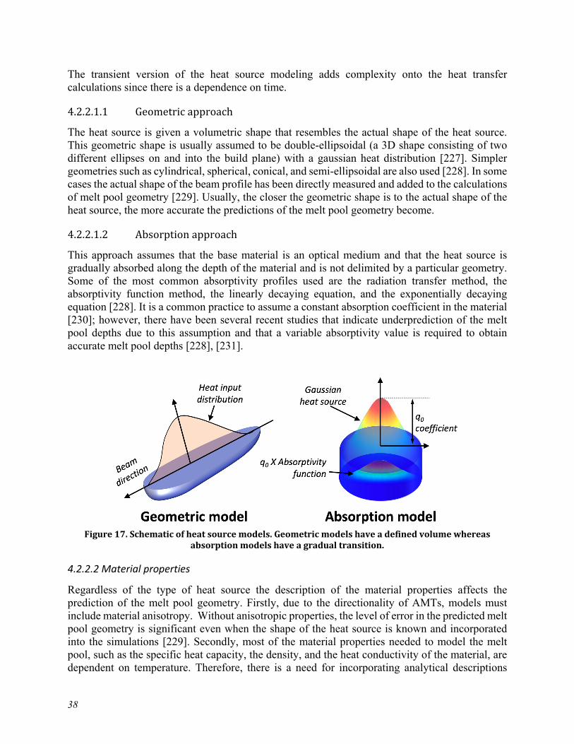
38
The transient version of the heat source modeling adds complexity onto the heat transfer calculations since there is a dependence on time. 4.2.2.1.1 Geometric approach The heat source is given a volumetric shape that resembles the actual shape of the heat source. This geometric shape is usually assumed to be double-ellipsoidal (a 3D shape consisting of two different ellipses on and into the build plane) with a gaussian heat distribution [227]. Simpler geometries such as cylindrical, spherical, conical, and semi-ellipsoidal are also used [228]. In some cases the actual shape of the beam profile has been directly measured and added to the calculations of melt pool geometry [229]. Usually, the closer the geometric shape is to the actual shape of the heat source, the more accurate the predictions of the melt pool geometry become. 4.2.2.1.2 Absorption approach This approach assumes that the base material is an optical medium and that the heat source is gradually absorbed along the depth of the material and is not delimited by a particular geometry. Some of the most common absorptivity profiles used are the radiation transfer method, the absorptivity function method, the linearly decaying equation, and the exponentially decaying equation [228]. It is a common practice to assume a constant absorption coefficient in the material [230]; however, there have been several recent studies that indicate underprediction of the melt pool depths due to this assumption and that a variable absorptivity value is required to obtain accurate melt pool depths [228], [231].
Figure 17. Schematic of heat source models. Geometric models have a defined volume whereas
absorption models have a gradual transition.
4.2.2.2 Material properties
Regardless of the type of heat source the description of the material properties affects the prediction of the melt pool geometry. Firstly, due to the directionality of AMTs, models must include material anisotropy. Without anisotropic properties, the level of error in the predicted melt pool geometry is significant even when the shape of the heat source is known and incorporated into the simulations [229]. Secondly, most of the material properties needed to model the melt pool, such as the specific heat capacity, the density, and the heat conductivity of the material, are dependent on temperature. Therefore, there is a need for incorporating analytical descriptions
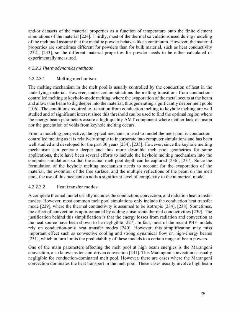
39
and/or datasets of the material properties as a function of temperature onto the finite element simulations of the material [224]. Thirdly, most of the thermal calculations used during modeling of the melt pool assume that the metallic powder behaves like a continuum. However, the material properties are sometimes different for powders than for bulk material, such as heat conductivity [232], [233], so the different material properties for powder needs to be either calculated or experimentally measured.
4.2.2.3 Thermodynamics methods 4.2.2.3.1 Melting mechanism The melting mechanism in the melt pool is usually controlled by the conduction of heat in the underlying material. However, under certain situations the melting transitions from conduction-controlled melting to keyhole-mode melting, where the evaporation of the metal occurs at the beam and allows the beam to dig deeper into the material, thus generating significantly deeper melt pools [106]. The conditions required to transition from conduction melting to keyhole melting are well studied and of significant interest since this threshold can be used to find the optimal region where the energy beam parameters assure a high-quality AMT component where neither lack of fusion nor the generation of voids from keyhole melting occurs.
From a modeling perspective, the typical mechanism used to model the melt pool is conduction-controlled melting as it is relatively simple to incorporate into computer simulations and has been well studied and developed for the past 30 years [234], [235]. However, since the keyhole melting mechanism can generate deeper and thus more desirable melt pool geometries for some applications, there have been several efforts to include the keyhole melting mechanism into the computer simulations so that the actual melt pool depth can be captured [236], [237]. Since the formulation of the keyhole melting mechanism needs to account for the evaporation of the material, the evolution of the free surface, and the multiple reflections of the beam on the melt pool, the use of this mechanism adds a significant level of complexity to the numerical model. 4.2.2.3.2 Heat transfer modes A complete thermal model usually includes the conduction, convection, and radiation heat transfer modes. However, most common melt pool simulations only include the conduction heat transfer mode [229], where the thermal conductivity is assumed to be isotropic [234], [238]. Sometimes, the effect of convection is approximated by adding anisotropic thermal conductivities [239]. The justification behind this simplification is that the energy losses from radiation and convection at the heat source have been shown to be negligible [227]. In fact, most of the recent PBF models rely on conduction-only heat transfer modes [240]. However, this simplification may miss important effect such as convective cooling and strong dynamical flow on high-energy beams [231], which in turn limits the predictability of these models to a certain range of beam powers.
One of the main parameters affecting the melt pool at high beam energies is the Marangoni convection, also known as tension-driven convection [241]. This Marangoni convection is usually negligible for conduction-dominated melt pool. However, there are cases where the Marangoni convection dominates the heat transport in the melt pool. These cases usually involve high beam
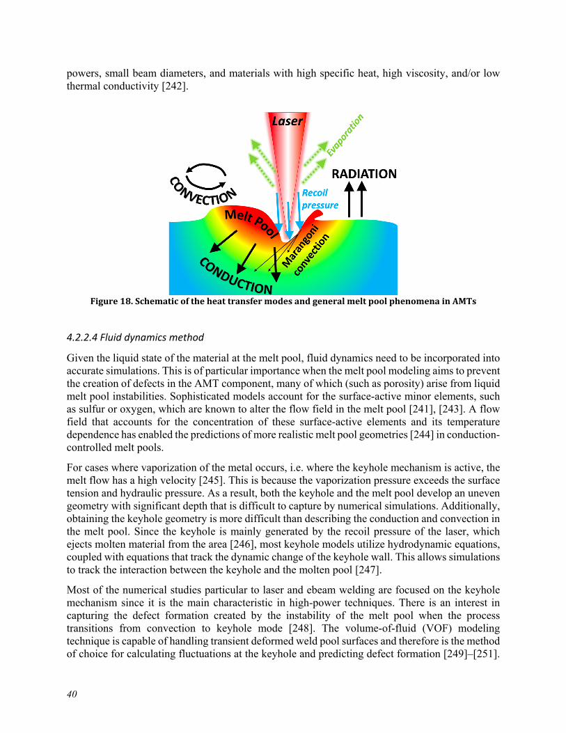
40
powers, small beam diameters, and materials with high specific heat, high viscosity, and/or low thermal conductivity [242].
Figure 18. Schematic of the heat transfer modes and general melt pool phenomena in AMTs
4.2.2.4 Fluid dynamics method
Given the liquid state of the material at the melt pool, fluid dynamics need to be incorporated into accurate simulations. This is of particular importance when the melt pool modeling aims to prevent the creation of defects in the AMT component, many of which (such as porosity) arise from liquid melt pool instabilities. Sophisticated models account for the surface-active minor elements, such as sulfur or oxygen, which are known to alter the flow field in the melt pool [241], [243]. A flow field that accounts for the concentration of these surface-active elements and its temperature dependence has enabled the predictions of more realistic melt pool geometries [244] in conduction-controlled melt pools.
For cases where vaporization of the metal occurs, i.e. where the keyhole mechanism is active, the melt flow has a high velocity [245]. This is because the vaporization pressure exceeds the surface tension and hydraulic pressure. As a result, both the keyhole and the melt pool develop an uneven geometry with significant depth that is difficult to capture by numerical simulations. Additionally, obtaining the keyhole geometry is more difficult than describing the conduction and convection in the melt pool. Since the keyhole is mainly generated by the recoil pressure of the laser, which ejects molten material from the area [246], most keyhole models utilize hydrodynamic equations, coupled with equations that track the dynamic change of the keyhole wall. This allows simulations to track the interaction between the keyhole and the molten pool [247].
Most of the numerical studies particular to laser and ebeam welding are focused on the keyhole mechanism since it is the main characteristic in high-power techniques. There is an interest in capturing the defect formation created by the instability of the melt pool when the process transitions from convection to keyhole mode [248]. The volume-of-fluid (VOF) modeling technique is capable of handling transient deformed weld pool surfaces and therefore is the method of choice for calculating fluctuations at the keyhole and predicting defect formation [249]–[251].

41
As a result, this technique is often used for most models that analyze the transition between melting mechanisms [249], [252]. Usually, the recoil pressure and the cooling from evaporation of the material are directly added onto the free surface of the melt pool. In general, the VOF technique is very flexible as it allows additions of interacting multi-physics phenomena and is capable of predicting the weld pools generated by high-powered lasers throughout the entire range of convection-to-keyhole modes.
4.2.3 Limitations and challenges
4.2.3.1 Homogeneous vs inhomogeneous media
Many of the prediction efforts focus on modeling the melt pool geometry at a continuum scale and in a homogeneous media since modeling the melt pool shape in the presence of a powder bed is extremely challenging. There have been efforts to model the melt pool generated in actual metallic powder where the melt pool exhibits fluctuations caused by the randomly packed powder bed [231], [253]. However, since modeling of powder particles has to account for their movement towards the high-speed metal vapor flux [254], different material phases [255], capillary effects of the molten metal/binder agent, sputtering, and several other complicated melt pool behaviors that arise from fluid dynamics, the powder-based models restrict themselves to a single scan line in the length of micrometers [231], [253]. Additionally, this type of multi-physics model results in a high computational expense.
On the flipside, incorporating the metallic powder onto a simulation allows the user to capture details of the melt track without requiring difficult experimental characterization, for example high-speed cameras capable of capturing extremely small features [254], [256]. Therefore, even if the modeling of the metallic powder is complicated and requires significant computational resources, it shows promise as a method to determine the optimal parameters that ensure consistently high-quality melt tracks.
An intermediate method to include the powder effects into the homogenous representation of the material during numerical simulations is by introducing the powder into the molten pool model using the discrete element method (DEM). The DEM is used to calculate the placement of individual particles given the particle size distribution and density in the metallic powder feed. Once the particle locations are known, the individual powder particles can be resolved using the VOF method described in 4.2.2.4, where the mesh size is refined down to the micrometer scale [257]. While this method is not capable of modeling entire scan layers, it is capable of modeling long scan lines, and consequently long melt pools, up to the millimeter scale. The DEM-VOF technique can also be used to assess the effects of the powder parameters on melt pool defects such as balling, cavitation, or discontinuities.
4.2.3.2 Multiphysics modeling
Many mechanisms such as material phase transitions, metallurgy, thermo-fluid dynamics, electromagnetism, plasma formation and beam-material interactions come into play during the development of the melt pool [252]. Accounting for all these phenomena for all weld pools may be excessive for some applications, especially as some mechanisms are negligible for certain materials and/or a certain type of melt pool. Modeling a melt pool therefore requires a careful examination of the phenomena that should be included or disregarded so that a representative

42
model can be developed without incurring neither over-simplification nor overly-complicated numerical models [229].
4.2.4 Use in optimizing processing parameters
Modeling of the melt pool has proven to be useful as a method to obtain a process window in which, given parameters such as scan speed or beam powder, the quality of an AMT component can be ascertained [258], particularly for emerging AMTs such as EBW for which a limited amount of simulation research exists and the resulting components are prone to defects like delamination or balling due to the deeper penetration of the beam. Typically, the optimal parameter settings for AMTs are determined experimentally and require a significant amount of time and resources [259] to determine. The main limitation in modeling the melt pool is that most of the models that have been verified with experimental characterizations have been limited to relatively low scan speeds because of the limitations in characterization equipment and the need to introduce more complex multi-physics phenomena into the simulations at higher scan speeds and for high energy beams.
4.3 Predicting solidification from melt
The modeling task here is to predict the grain morphology (e.g. structure, size, and orientation) given a description of the thermodynamics of cooling, perhaps modeled with the techniques described in 4.2.4. As described in 3.3.1.1 two key variables control the morphology of the solidified grain: the temperature gradient and the solidification rate [51], [260]. Both of these variables are outputs from the melt pool modeling described in the previous section. As the adjacent, unmelted solid material provides ample nucleation sites [94] the process is dictated by the kinetics of grain growth, though the orientation of the unmelted solid may influence the orientation of the new grains. As the previous section describes modeling and simulation techniques for the melt pool geometry and the previous chapter details the physics of the grain growth process, this section focuses solely on modeling techniques for predicting grain structure given the solidification rate, temperature gradient, and other thermodynamic information.
4.3.1 Processing maps
Figure 19 shows a typical processing map for AMT powder-bed processing of a metallic material. The x- and y-axes of the plot are the solidification rate ( ) and the temperature gradient ( ). The plot shows typical regions of grain morphology depending on the values of and . Also show
43
are lines indicating constant grain size distributions following contours of constant values of ×. The AMTs discussed here fall on the lower right portion of the diagram.
Figure 19. Representative solidification processing map.
In the welding literature, a great deal of experimental and modeling work has been devoted to determining these diagrams for different materials and welding processes [261]. While they are simplistic descriptions of a complicated process, they contain a great deal of practical engineering information. For example, a relatively high proportion of equiaxed grains is required for many AMTs to achieve isotropic material properties [51] and so a processing diagram might be used to target the equiaxed region of , space, which in turn might be translated into actual processing parameters using the melt pool modeling techniques described in 4.2
Of course, processing maps are not a modeling technique; they are a method for summarizing the results of a collection of experiments or simulations into practical information. However, they are mentioned here for two reasons:
1. They are often generated through modeling and simulation methods. Any of the more sophisticated, full-field simulation methods discussed below can be used to generate processing maps of this type and there is a large body of historical literature from the welding and casting community on generating maps using simple models based on ordinary differential equations (c.f. [94], [262]–[265]). Even for experimentally-generated maps some interpolation method is required to fill in the diagram between the limited experimental data. Often a model provides this interpolation.
2. Processing maps provide a quantitative method for validating sophisticated modeling and simulation techniques. The details of material microstructure in AMT processes are more complicated than a simple description of an average grain size and grain morphology and the sophisticated simulation methods described below aim to predict these details. However, the simple information encoded in a processing diagram provides a quantifiable link to experimental data and provides the best, simple connection between sophisticated
Constant grain size

44
models and actionable information for end-users. Put another way, when the modeling and simulation techniques described here can accurately predict processing maps from limited prior information manufacturers will be able to use these sophisticated models to optimize manufacturing processes and the final material microstructures.
4.3.2 Simulation methods for grain growth and nucleation
Two numerical methods dominate the body of literature on simulating grain solidification: cellular automata methods and the phase field approach [266]. Though the two methods fundamentally model the same process – the nucleation and growth of solid metallic grains starting from melt – the implementations differ greatly. Cellular automata approaches are often stochastic and solve the problem over a discrete solution space while the phase field method is deterministic and based on a continuum field theory (although numerical implementations must discretize the underlying equations). Our review of the literature shows that both approaches are about equally popular when addressing the AMT problem of solidification in PBF and DED processes. Cellular automata approaches were perhaps historically more popular and in the most recent literature phase field approaches seem to be somewhat more prevalent. The strengths and weaknesses of each approach are discussed here, along with a description of the model formulation and a brief survey of literature specific to the AMTs of interest.
4.3.2.1 Cellular automata
The concept of cellular automata originates with von Neumann [267] but practical models for solidification were developed only in the late 1980s and early 1990s [268], [269]. These models work with a discrete, voxelated discretization of the region of interest. Each individual cell exists in one of several finite states – models always include “liquid,” “interface,” and “solid” states. Figure 20 illustrates a typical discretization. Models often contain specialized states, for example a “powder” state distinct from the state of resolidified metal for AMT applications [270]. The model consists of a series of typically stochastic rules that dictate the transition in each cell from one state to another. For example, a rule might provide a probability that a particular cell transition from the “liquid” to the “interface” state based on, among other factors, the number of neighboring cells that have already transitioned to the “solid” state.
Figure 20. Typical cellular automata discretization of a domain into a regular grid of cells with each
cell here being in either the Solid, Interface, or Liquid state.
S
S
S
I
L L L L L
I L L L
S I L L
S I L L
S I L L

45
These rules require information from underlying field equations (heat transfer and diffusion), which can be solved with either finite difference (i.e. Cellular Automata Finite Difference, CAFD, methods) or finite element (i.e. Cellular Automatic Finite Element, CAFE, methods) discretizations, as well as simple rules based on microscale models of dendritic front growth. These rules are assembled and then the simulation marched forward in time with a suitable time stepping scheme. Oftentimes using different numerical grids and different time stepping schemes for the CA method and the field equations is required to assemble a stable numerical method. In addition to the CA state and the field variables, the cells also typically contain a state variable representing the crystal orientation of the cell when it is in the solid state. This orientation is often determined through relatively simple rules, for example randomly selecting the orientation of nucleation sites or assuming some preferred orientation [271]
The advantages of cellular automata methods are numerical efficiency and relative simplicity in implementation. Additionally, stochastic nucleation is relatively easy to implement in the framework (though it may not be significant when modeling powder-based AMT processes, as described in 3.3.1.1). The disadvantages include sensitivity to the discretization often caused by the requirement of piecing together a smooth liquid/solid interface from an inherently discrete geometry and the limited embedded physics inherent in the transition rule approach. Some of these disadvantages can and have been overcome [268] through various numerical improvements to the original model formulation.
CA methods were originally conceived for casting simulation and quickly applied to welding problems [272], [273]. There have been numerous recent applications to PBF and DED solidification problems. Early models of laser and ebeam processes were two dimensional (c.f. [274]–[277]), but more recent applications are full-field 3D representations (c.f. [271], [278]). Nearly all of these studies include at least limited validation against specialized, often single-pass experimental studies.
4.3.2.2 Phase field
The phase field method is a general method for modeling phase transformation problems. In this technique each phase is represented with a different field variable , called an order parameter, often defined to range from 0 to 1 [279] (though the scale of the order parameter is arbitrary and methods sometimes use [-1,1]). A value of = 1 means the point in the continuum is entirely composed of the phase associated with order parameter and values between 0 and 1 indicate a mixed-region combining multiple phases. Figure 21 illustrates a typical continuum phase field description of a solid/liquid interface. The simplest models of solidification only require a single order parameter, typically with = 0 indicating the liquid phase and = 1 indicating the solid phase [280]. However, models of crystalline grain solidification in metals will typically require a
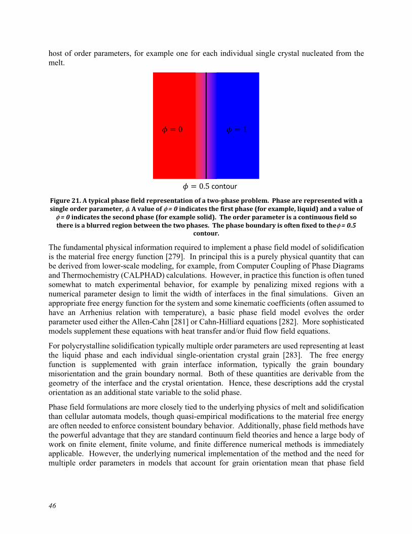
46
host of order parameters, for example one for each individual single crystal nucleated from the melt.
Figure 21. A typical phase field representation of a two-phase problem. Phase are represented with a single order parameter, φ. A value of φ = 0 indicates the first phase (for example, liquid) and a value of
φ = 0 indicates the second phase (for example solid). The order parameter is a continuous field so there is a blurred region between the two phases. The phase boundary is often fixed to theφ = 0.5
contour.
The fundamental physical information required to implement a phase field model of solidification is the material free energy function [279]. In principal this is a purely physical quantity that can be derived from lower-scale modeling, for example, from Computer Coupling of Phase Diagrams and Thermochemistry (CALPHAD) calculations. However, in practice this function is often tuned somewhat to match experimental behavior, for example by penalizing mixed regions with a numerical parameter design to limit the width of interfaces in the final simulations. Given an appropriate free energy function for the system and some kinematic coefficients (often assumed to have an Arrhenius relation with temperature), a basic phase field model evolves the order parameter used either the Allen-Cahn [281] or Cahn-Hilliard equations [282]. More sophisticated models supplement these equations with heat transfer and/or fluid flow field equations.
For polycrystalline solidification typically multiple order parameters are used representing at least the liquid phase and each individual single-orientation crystal grain [283]. The free energy function is supplemented with grain interface information, typically the grain boundary misorientation and the grain boundary normal. Both of these quantities are derivable from the geometry of the interface and the crystal orientation. Hence, these descriptions add the crystal orientation as an additional state variable to the solid phase.
Phase field formulations are more closely tied to the underlying physics of melt and solidification than cellular automata models, though quasi-empirical modifications to the material free energy are often needed to enforce consistent boundary behavior. Additionally, phase field methods have the powerful advantage that they are standard continuum field theories and hence a large body of work on finite element, finite volume, and finite difference numerical methods is immediately applicable. However, the underlying numerical implementation of the method and the need for multiple order parameters in models that account for grain orientation mean that phase field
= 0 = 1
= 0.5 contour

47
approaches are typically numerically more expensive than corresponding discrete cellular automata models.
There are numerous examples of applying phase field formulations to modeling solidification in PBF and DED systems. Many of these studies include validation, albeit oftentimes qualitative, against experimental PBF (c.f. [284]–[287]) or DED (c.f. [288]) studies. These AMT works are in addition to a wide body of literature focusing on weld solidification (c.f. [289]) which is also generally applicable to the fusion-based AMTs. The validation studies show that the method is generally successful in predicting grain morphology and grain growth directions and somewhat successful at predicting the final material texture when compared to single weld passes. Much less work has been done with phase field methods for more realistic multi-pass simulations, likely because of the computational expense.
4.3.2.3 Other techniques
A third, somewhat less common, technique is to model each phase (i.e. grain) as separate but interpenetrating continua [290]. With this approach the numerical method solves separate mass, momentum, and energy (heat transfer) balance equations for each separate phase with either ad hoc or physically-based mixing rules describing the interaction of phases. This approach quickly becomes very burdensome for large numbers of phases, making it less suitable for simulations of solidification where the method attempts to resolve the grain orientations. However, it has been successfully applied to two-phase solidification problems, where it can provide very detailed resolution on the melting and resolidification processes [291], [292].
In addition to the aforementioned disadvantage of the ad hoc nature of phase interfaces in these formulations, they suffer the additional disadvantage of typically requiring very small, explicit time steps to resolve the material physics. However, they do bring to bear on the solidification problem a well-established set of simulation methods developed in the fluid dynamics and hydrodynamics communities.
4.3.3 Challenges in deriving comprehensive models
A base model for solidification only considers the phase change problem. Thermal conditions can be imposed separately and the method need not solve the heat transfer problem. However, as the physics of solidification is strongly tied to the problem of heat transfer most, if not all, applications to AMTs also solve heat transfer. Some, but not all, of the applications include a description of fluid flow in the liquid phase, which allows these models to capture the effect of Marangoni convection on the solidification process.
Multiphase solidification problems seem to be seldom considered in AMT applications. While several papers model the solidification of Ti-6Al-4V [288], [293]–[296] we were not able to identify any that separately resolve either the hexagonal close-packed crystalline structure, called the alpha ( ) phase, or the body-centred cubic structure, called the beta ( ) phase. Likely this is due to the difficulty in adding additional order parameters and the additional, diffusive/chemical potential physics required to model mass transport in the binary system. Similarly, studies do not yet explicitly consider the formation of second-phase precipitate structures, likely again because

48
of the numerical difficulty in adding additional physical phases and the difficulty of resolving the physical scales of both the bulk grain and small-scale precipitate structures.
Very few studies of solidification explicitly consider the formation of voids in the solidified material. Again, this is partly due to the difficultly of including yet another phase (here vapor or void) and the required additional transport physics. A notable exception are the hydro/fluid-dynamic methods that can model the void phase with relatively limited theoretical complications.
Grain recrystallization and growth will typically occur in underlying layers beneath the melt pool. Very few studies explicitly examine the effect of these processes on the final, simulated microstructure. Both phase field and cellular automata methods are eminently suitable for modeling these processes (see Section 4.4) and so it is likely the numerical cost of implementing multi-pass models preventing the development of such models. Similarly, very few studies of solidification integrate residual stress and distortion prediction into the models, even though of course the solidification process is one key contributor to the development of residual stress. Again, it is likely that the development of these types of simulations is limited by the difficulty of incorporating yet another set of physics (i.e. stress equilibrium in the solid phase) into the modeling framework.
4.4 Predicting grain growth and densification
Both classical sintering and models of the HIP process are primarily concerned with the tradeoff between densification, i.e. the removal of internal porosity, and grain growth. A complete process model focusing on this critical tradeoff therefore needs to include individual models for both phenomena in a combined framework.
4.4.1 Modeling recrystallization
Recrystallization is the formation of new grain structures in a deformed material by the formation and migration of high angle grain boundaries driven by stored deformation energy [171], [297] . The importance of recrystallization as a metallurgical processing technique has been well-acknowledged for many years now, especially since the macroscopic properties such as ductility, strength, and resistance to creep deformation are largely governed by the recrystallized microstructure which can be controlled by appropriately tuning the recrystallization process parameters. Recrystallization is broadly classified into two types – static and dynamic recrystallization. During static recrystallization no new deformation is imposed on the material and grain boundary migration occurs in order to balance the stored deformation energy and the grain boundary curvature energy. In dynamic recrystallization the material continues to undergo plastic deformation thereby leading to the formation of new high angle grain boundaries which then migrate to minimize the free energy of the system. The process of recrystallization is often preceded by nucleation of new grains having lower strains, which then subsequently grow at the expense of highly deformed grains (i.e., grains with high dislocation densities) around them [298]. Typical nucleation sites are locations with a high misorientation gradient as well as heavily deformed regions in the polycrystal [171].
In classical models of recrystallization, the kinetics of the process is addressed using the Johnson-Mehl-Avrami-Kolomogorov (JMAK) relation. It gives an exponential relationship between the fraction of recrystallized grains with time. The time exponent is often hypothesized to contain microstructural information such as site-saturated nucleation and two dimensional growth

49
(exponent value of 2) or continuous nucleation with three dimensional growth (exponent value of 4) [299]–[301]. Apart from the classical model, attempts have also been made to predict the recrystallization process through empirical methods using the Zener-Hollomon parameter to estimate recrystallized grain size and time to 50 % recrystallization [302]–[304], as well as using advanced statistical methods [305], though these do not provide any physical insight into the process [306]. Models which simulate the recrystallization process as an initial nucleation step followed by a continuous growth of these nuclei, often consider a critical dislocation density [307]–[311] and a critical misorientation angle [312]–[315] as a criteria for the nucleation event. The subsequent growth velocity is then formulated as a product of net driving force (being a function of local grain boundary curvature, stored strain energy, and presence of impurities) to the grain boundary mobility that can also be a function of local misorientation [169], [316], [317]. Such a formulation of the recrystallization phenomena forms the basis for more sophisticated continuum models using either phase-field approaches or cellular automata as well as discrete Monte Carlo Potts models.
The Monte Carlo (MC) Potts model, which is a generalization of the Ising model, has been used to model both static [318] and dynamic recrystallization [319] and sometimes has also been coupled with visco-plastic crystal plasticity models [315], [318] to extract deformation information. To perform such analysis, the microstructure is first mapped into a cubic lattice where each lattice site is assigned a crystallographic orientation. The total energy of this cubic lattice is taken as a function of both misorientation and dislocation density summed over all the lattice sites. The evolution of the grain microstructure is then employed by Monte Carlo sampling of the lattice sites, where a change to the state of a site is accepted or rejected based on a switching probability [299], [300]. Even though the MC Potts approach to model recrystallization is frequently used due to its versatility and flexibility to represent many different physical features of the recrystallization process (such as overall texture evolution [320]), until very recently [321], this methodology excluded the grain-scale micromechanical effects on recrystallization process in a full-field sense. Such effects have mostly been incorporated using crystal plasticity models coupled with either phase-field equations or the cellular automata approach.
In coupled crystal plasticity (CP) - cellular automata (CA) approaches the grain-scale plastic deformation behavior is predicted by crystal plasticity simulations either using a grid based finite-element solver [313], [314], [322], [323] or a voxel-based fast Fourier transformation solver [312], [324], [325]. In this approach the results from a (generally) coarser grid CP simulations are first interpolated into a finer and regularly spaced cellular automata grid where the conditions of nucleation and grain growth during the recrystallization process is evaluated. More often a probabilistic switching criterion for each automaton cell is prescribed which determines its probability of being consumed by another cell, similar to the transitional probability criteria in the Monte Carlo (MC) Potts method. The CA approach is an attractive avenue of research as it provides high spatial resolution and scalability for computer code parallelization, thereby giving a higher computation efficiency for full-field coupled calculations. However, critical disadvantages of the method include the inability to trace the texture evolution in the material, as well as the significant dependence of the evolving grain morphology on the underlying CA grid discretization [301], [326].
In phase field recrystallization models, the grain structure is represented through a continuous phase field with distinct values in each grain, often with diffuse interfaces across the grain boundaries. The crystallographic orientation of each grain is represented through the non-
50
conserved phase-field variables, and the subsequent driving force for recrystallization is governed by minimizing the free-energy functional of the system that consists of components related to the interfacial energy, bulk energy, and stored strain energies. The simulation is then governed by the time-dependent Ginzburg—Landau [327] and Allehn—Cahn [328] equations, which are then solved using numerical schemes such as finite difference methods, finite element methods, or spectral decomposition. Different phase-field formulations of recrystallization differ in the formulation of this free-energy functional, with inclusion of more terms (i.e., incorporating more physics) adding to the numerical and computational complexity. The coupled phase-field crystal plasticity approach has been employed to simulate both static and dynamic recrystallization processes [329]–[333] as well as for systems with anisotropic grain boundary properties [334]. The phase-field approach to recrystallization may become computationally expensive when considering large number of grains. However, recent studies provide methods for uniquely representing more than one grain with a single non-conserved order parameter reduce the computational memory requirement significantly [335], [336].
Other methods of modeling recrystallization include vertex or front tracking methods [337], and level set models [338]–[341]. The front tracking method has the advantage of including a physical time scale [342] but has been restricted mostly to two-dimensional investigations due to numerical and computational complexity. The level set method, which resembles the phase-field approach, is a relatively recent technique that has not yet been fully explored in the literature.
4.4.2 Modeling densification
Models of densification can be split into two types: continuum models using macroscale poroplasticity and diffusion models to predict the densification of large volumes and discrete models that resolve individual powder particles. Historically, discrete models can only simulate the densification of relatively small volumes of material, but recent developments in the Discrete Element Method (DEM) have enabled discrete simulations of larger volumes of material.
4.4.2.1 Continuum methods
Continuum methods for predicting sintering compaction have a long history and have been successfully applied to predict densification in a variety of manufacturing processes. The key aspect of these methods is that the treat the part as a continuous, albeit porous, medium, neglecting the details of individual particle-to-particle interactions. Within this category are two subclasses of models: one for continuous mechanical densification and one for diffusion-based densification. Section 3.3.2.1 describes the physical mechanisms governing these two densification processes. In general, mechanical densification is more important in the PM-HIP process and diffusion-based densification is more important in classical sintering. However, both mechanisms can occur in either process. Chapter 3 provided an overview of the physical processes underlying each mechanism, this section focuses on particular modeling techniques.
Models for physical densification are at heart simply classical, continuum poroplasticity methods. These models are rooted in either the Gurson [343] or Fleck [344] formulations, which both provide a constitutive equation describing the plastic growth or shrinkage of voids distributed in a solid medium. The Gurson and Fleck models and their numerous extensions by Hutchison, Needleman, Tvergaard, and others [345], [346] were originally intended for void growth leading to fracture. However, numerous studies have applied this framework to model densification (i.e.

51
void shrinkage) in PM-HIP processes and shown good agreement with experimental tests [347]–[349]. Alterative poroplasticity formulations have been used (e.g. [350]–[352]), however they all share the key constitutive form: given the stress predict the evolution of plasticity (plastic strain) and porosity (void fraction) over a time increment: , , → ̅ ,
where is the stress, the porosity, the temperature, and ̅ the equivalent plastic strain. This scalar model would be supplemented with a flow rule to determine the complete inelastic strain rate tensor.
Models for the growth or collapse of voids via plastic deformation can be linked to models for the evolution of plasticity in bulk material (cf. [351]). The task is then determining which plasticity mechanisms to represent. Models typically include some form of power law creep, occasionally supplemented by high temperature, diffusional mechanisms like Coble or Nabarro-Herring creep.
Once assembled into a complete poroplasticity model any standard finite element framework, including commercial software like Abaqus or ANSYS, can be used to execute the densification simulations. To the finite element framework the poroplasticity model looks like any other standard inelastic constitutive model. The user applies the appropriate boundary conditions, for example a suitable pressure boundary condition for the PM-HIP process or loading conditions representing the mechanical loads induced by traditional pressing. The finite element simulation then models the evolution of deformation in the component according to the underlying poroplasticity model. The internal porosity is a state variable in the poroplasticity model and so a direct prediction of densification is also an outcome of these simulations.
The various parameters required in the poroplasticity model are fit to experimental data – either simple or complicated particle compression tests. These parameters typical depend on temperature and so a series of tests may be required.
Sintering can be fit into the framework of poroplasticity through models for the “sintering stress.” This sintering stress is the effective, macroscale stress provided by the thermodynamics of microscale, diffusional, pore-collapse mechanisms available to reduce porosity. Early work originates with Ashby [353], though [354] provides a more modern summary. Once this sintering stress is determined, the remainder of the macroscale simulation can be completed using a standard finite element framework. For pure sintering, the only required input information is the temperature field in the component and any constraint conditions provided by a tool or die. However, models for diffusion induced and stress induced pore collapsed can be combined by summing the mechanical stress and the sintering stress. In this case mechanical boundary conditions are also required.
Various models for the sintering stress have been proposed [355]–[358] all typically derived from simplified micromechanical models of transport. These models relate the microstructural characteristics affecting diffusion-driven mass transport to a macroscale, effective sintering stress that can be used to drive a poroplasticity model.
4.4.2.2 Discrete methods
An alternative to the continuum approach discussed in 4.4.2.1 is a discrete approach that directly represents each individual metal particle and pore. Again, there are discrete approaches for both

52
mechanical consolidation and sintering and again these approaches can be combined into a composite model.
Early work on discrete models of mechanical consolidation relied on finite element methods or analytic solutions [232], but more recent models adopt the Discrete Element Method (DEM) [359]–[362]. DEM is a discretization technique aimed specifically at efficiently simulating the behavior of a large number of particles [363]. Recent advances in the method allow the technique to model details of contact forces between particles with irregular shapes and sizes and to represent aggregates of millions of particles.
The advantage of DEM-based simulations of HIP consolidation is that they directly represent the microstructural features affecting consolidation – particle size and shape distribution and the details of plasticity inside each particle. The disadvantage is that the scale of these models still remains limited – realistic HIP parts might have billions of individual metal particles.
There are corresponding discrete models for sintering. Here again modern models are set in the context of the DEM [364]–[366]. The direct analogy of a “sintering stress” is a “sintering force” driving the consolidate of the powder bed. As with the continuum models, this sintering force is determined from the thermodynamics of the underlying diffusion-driven mass transfer processes.
The discrete methods for sintering share similar advantages and disadvantages to the discrete methods for mechanical consolidation: they directly incorporate many of the key processing variables like powder shape and size, but remain limited in scale based on the requirement of resolving individual particle-particle interactions.
4.4.3 Challenges developing complete process models
A complete process model for sintering or HIPing typically combines a model for consolidation along with a model for grain growth. As discussed in Section 3.2 there are many additional microstructural features that feed into the final material properties. However, the classical tradeoff in sintering and HIPing is between grain size and porosity. Higher pressures and temperatures and longer times lead to less porosity but larger final grain sizes, which tend to result in impaired mechanical properties. A successful process model tries to steer the key processing parameters of pressure, time, and temperature to a regime that produces near full consolidation without excessive grain sizes.
Conceptually, a complete process model then combines a grain growth model (Section 4.4.1) with a model for consolidation (Section 4.4.2). Many researchers have claimed success modeling either HIPing or classical sintering with these sorts of models for particular geometries (c.f. [367]–[372] among many others). However, the vast majority of these compare only to experimental distortion measurements and not key microstructural characteristics. Furthermore, these were for the most part “one-off” studies and not general process models applicable to any part geometry and material.
Instead, common commercial practice relies on HIP or sintering diagrams. These are simple plots of density versus temperature (classical sintering) or pressure at fixed temperature (HIPing) [353], [373]–[375]. Occasionally, corresponding plots of grain size or some other mechanical property versus the same variables supplement the basic diagram. Using these diagrams, a process engineering can determine appropriate processing conditions to achieve the required density while avoiding detrimental grain growth. Oftentimes, the diagrams are constructed using models
53
calibrated to experimental data or, occasionally, physically-based micromechanical models of the type discussed in the previous section.
The process diagram approach is crude: it abstracts most of the key micromechanical processing variables identified in 3.3.2 (or rather a separate processing diagram is required for each powder material, powder size, power shape, etc.). However, it has the crucial advantage of simplicity – once collated a set of processing diagrams can be distributed and widely and easily used to tune the manufacturing process.
More sophisticated process models of HIPing and sintering are achievable with well-validated current technologies. However, we have not been able to identify any commercial product offering such a model (here we are not counting consulting engineering services that offer to develop bespoke models using commercial FEA). To some extent this likely reflects a lack of demand – conventional sintering is a well-established process and practitioners seem content with trial and error supplemented by processing diagrams while HIPing is not a widely used manufacturing process. This will likely change in the future as these technologies are applied to AMTs – for example, it would be difficult to achieve optimal sintering parameters for binder-jet green parts if many different, or even individually unique, geometries are being produced. However, the current state-of-the-art in manufacturing relies on simpler techniques, even though more sophisticated models are available and frequently used in research programs.
4.5 Summary and Recommendations
This section surveys physically-based modeling approaches for predicting the initial microstructure of AMT materials. The chapter covers both fully-resolved multiscale approaches as well as classical homogenized, macroscale models. Basic techniques for predicting limited sets of microstructural characteristics given a single or a single related set of processing variables are well-developed. Complete modeling frameworks as less well developed, given the challenges in bridging time and length scales.
Of the different microstructure features surveyed here, models for the initial residual stress distribution are the most well-developed. Commercial simulation tools are already developed. Close behind are tools for the densification of material in PM-HIP processes. Models for PBF and DED techniques, as well as detailed electron-beam welding models, are less developed. However, much progress is being made, particularly for models with comparatively limited scale, for example predicting processes in a single weld line.
This chapter briefly touches on verification and validation – Chapter 7 “Key Recommendations” expands on this topic in greater detail. However, one key point is the relative lack of microstructural benchmark problems for assessing various prediction methods. Despite some progress by NIST and others in assembling suites of benchmark problems, complete microstructural benchmarks are relatively rare given the wide variety of AMT processes, the complexity of resulting microstructures, and the difficulty inherent in characterizing reasonable volumes of material in detail. The development and community acceptance of such benchmark problems would of great value to regulators, as they could serve as a standard for the acceptance of new (and existing) modeling and simulation techniques.


55
5 Data-based prediction methods
5.1 Introduction
Machine learning (ML) and other statistical approaches have seen increasing adoption in materials science and engineering including the development of processing-structure (P-S) relationships [376]. A subset of these approaches target additive manufacturing, a field characterized by complex processing conditions with numerous variables of interest. For a target AMT, for example laser PBF, internal machine variables (e.g. laser power, scan speed and hatch spacing) in addition to external variables (e.g. powder quality and environmental conditions) directly and complexly influence microstructure characteristics (e.g., grain size distribution, spatial composition fields, spatial orientation fields, porosity, cracking, and phase fraction). As discussed in the previous chapters, traditional physics-based approaches can be used to connect processing to structure. Phenomenological approaches employ simple, physics-informed expressions with parameters calibrated by experimental data. Sophisticated physics-based modeling approaches address specific aspects of an AMT and include FEM, CALHPAD, phase-field modeling, cellular automata, and more. Machine learning has the opportunity to replace elements of these traditional approaches, or even to replace them wholesale. In the first category, a ML model may be trained as a surrogate of a slow to evaluate physical-model, or be employed to accelerate the predictions of such a model. In the second category, ML may be used as a substitute for phenomenological models and directly connect processing parameters to microstructure outcomes. The advantage in this second case is that ML approaches can realistically incorporate dozens of input variables when connecting to microstructure in a simpler and more direct way than a chain of physics-based models or phenomenological models.
Machine learning for AMTs is a relatively new area of research with limited numbers of available studies. That said, we expect that existing approaches not specific to AMTs will be transferable between materials systems and AMT methodologies. The literature is not mature enough to target nuclear applications specifically, so this chapter discusses all known ML studies for predicting microstructure in AMT. The remainder of this chapter discusses several major categories of studies where ML has been applied to AMT. The first covers simple processing-structure maps which characterize regimes of build quality and microstructure as a function of processing variables – typically in two dimensions. The second discusses ML processing-structure relationships that connect processing variables to either simple microstructure metrics or comprehensive microstructure representations [377]. Third, we discuss statistical approaches that produce microstructure-relevant predictions with quantified uncertainty. This last category, while not explicitly ML, will likely play an important role in the qualification of microstructure prediction methods for AMT components with nuclear applications. The section concludes with an assessment of the state of ML in AMTs and prospects for its application in the nuclear energy space.
5.2 Processing-structure maps
Processing-structure maps are tools that provide guidance on microstructure and or defect characteristics for a given process and material. Typically, these maps are a function of two processing variables that have been determined to be the most influential (e.g. laser power and scan speed in L-PBF). These are useful tools to help determine operating conditions that will result
56
in desirable microstructures and low defect rates. Typically, processing-structure maps would not be considered “ML tools,” as they represent a highly simplified view of the process data and may be manually constructed [378]. That said, they are similar to ML approaches in that they provide a “shortcut” or “surrogate” to the results of a highly complex physical process. In the remainder of this sub-section we will discuss several examples of processing-structure maps in the AMT literature.
In 2017 Liang et al. presented the development of processing-structure maps for laser-additive manufacturing of Ni-base superalloys [379]. In this work, the authors developed maps for build quality versus laser power (P), scan speed (V), and the powder feeding rate (m). As maps can only be easily visualized in two dimensions, maps were presented for P vs V and P vs m at different V and m levels, respectively. Due to the high computational cost of evaluating FEM models for a grid of processing conditions, the authors relied on analytical heat transfer models as a function of laser processing variables. Then a microstructure selection model was employed to relate the thermal conditions to solidification microstructure, specifically the columnar to equiaxed transition.
In 2018 Mutua et al. developed a processing-structure map for L-PBF of maraging steel [380]. In that work they studied the impact of processing parameters including laser power, scan speed, pitch, and spot diameter on relative density, surface morphology (e.g. balling, shrinkage, and undermelting), and mechanical properties. In contrast to the previous study. This map was entirely experimentally constructed and required large number of experiments. This study resulted in a processing-structure map that identifies zones of varying structure optimality (and associated defects) for scan speed versus laser power.
In 2019, Johnson et al. developed a computational workflow to predict processing-structure maps in L-PBF based on FEM [381]. This FEM framework was developed using COMSOL’s heat transfer module, and incorporated phase dependent properties to understand phenomena including melting, solidification, keyhole formation and vaporization. After identifying laser power and scan speed as the critical parameters, the authors used this FEM framework to produce printability maps for Ni-5wt.%Nb and a CoCrFeMnNi high entropy alloy. These maps identify regions of good quality, keyholing, balling, and lack of fusion. The authors also constructed printability maps based on the Eagar-Tsai model [382] and demonstrated that this simplified modelling approach was inadequate to represent the experimentally determined printability maps. Finally, the authors used a Gaussian process surrogate model to investigate uncertainty in the mappings [383]. We discuss this final aspect later in this chapter.
5.3 Machine learned processing-structure relationships
The primary opportunity for machine learning in additive manufacturing is to predict material structure and properties from the starting constituents, processing conditions, and build path. Ideally, this can be performed with high accuracy and will not require on-demand high-performance computing (though calibration of these linkages may require extensive experimental or simulation campaigns). As previously mentioned, the multi-physics computational approaches required to model additive manufacturing are frequently complex and multi-stage. Machine learning has an opportunity to replace individual components in these model chains, or to represent the process start to finish. In the latter case, machine learning can also use experimental information that directly connects processing to the material microstructure. Unfortunately, the
57
authors have only identified two ML approaches in the literature that attempt to address this challenge in AM. In the remainder of this section, we discuss these two approaches.
In 2017, Popova et al. published the first work (that the authors are aware of) that addresses ML processing-microstructure linkages in AM. This work was based on the Materials Knowledge Systems (MKS) framework developed by Kalidindi and colleagues for data-driven processing-structure-properties relationships in a variety of materials systems [384]. The philosophy of this approach is that materials processing and properties/performance must be linked by microstructure. Therefore, ML relationships rely on effective quantifications of microstructure. In this particular work, processing-microstructure relationships in laser-based additive manufacturing were developed for microstructures simulated using a Potts-kinetic Monte Carlo approach. Through the simulation of 1799 microstructures, the authors addressed the impact of simulation variables relating to AMT processing variables including the scan pattern, scan velocity, molten zone geometry and heat affected zone geometry. The resultant microstructures were quantified using chord length distributions for each of the principal axes [385]. For a given axis, this provides a histogram for the dimensions of grains at a large number of random locations in the microstructure. These chord length distributions were transformed into a reduced-dimensional space using principal component analysis [386]. Finally, processing conditions were linked to the reduced-dimensional microstructure representations using simple polynomial expressions selected via cross-validation [387]. While predictions of these reduced-dimensional microstructure representations are not easily inverted to retrieve microstructure images, they can be connected to traditional microstructure characteristics (e.g. grain size distribution) or directly to properties.
In 2019, Gan et al. published a machine learning approach that resulted in a full processing-microstructure-property linkage for DED of Inconel 718 [388]. This work is unique in that it leveraged diverse experimental and computational approaches. The authors related processing variables including laser power and mass flow rate to dendrite arm spacing and Vickers microhardness. From the computational perspective, the authors simulated the DED process resulting in energy densities and cooling rates, with which the dendrite arm spacing and microhardness could be estimated using mechanistic models from the literature. The authors also produced samples via DED and characterized their structure and hardness. All of the processing variables, derived processing characteristics (cooling rates and energy density), the dilution and micro-hardness were used as inputs to a Self-Organizing Map (SOM) [389]. SOMs are an unsupervised machine learning approach similar to feed-forward neural networks that perform dimensionality reduction on the inputs. It is common to create a 2-dimensional map for ease of visualization. In general, the resulting map represents the training example such that neighboring examples are similar and far apart examples are dissimilar. From the self-organizing map, the authors suggested processing parameters resulting in desirable dendrite arm spacing and microhardness.
5.4 Uncertainty quantification and sensitivity analysis
In 2016, Kamath used a multi-component machine learning approach to perform statistical inference for the melt pool depth in SLM of 316L SS [390]. Prediction of the melt pool depth is not sufficient to be considered as a processing-microstructure linkage, however the work goes into some depth in putting together a comprehensive predictive framework with quantified uncertainty. In the first stage, Kamath uses an Eager-Tsai model to predict melt pool dimensions, and compares the results against single line scans. While the prediction accuracies were not good, it was
58
sufficient to identify laser power and scan speed as the most influential variable through the use of a parallel coordinate plot and other feature selection algorithms. These results were used to construct a surrogate model for the melt pool depth based on an ensemble of decision trees. Next, Kamath moved to higher fidelity and computational expense Verhaeghe model to predict the melt pool depth [391]. These results were much closer to experimental values than from the Eager-Tsai model. As fewer of these calculations could be performed, in this case a Gaussian process model was employed to fit the data, providing uncertainty estimates alongside the mean predictions.
In 2019, Nath et al. developed a computational workflow to predict grain morphology in laser direct metal deposition (LDMD), quantify its uncertainty, and perform sensitivity analysis on the input variables [392]. The authors used a FE model to predict the melt pool shape, and microscale cellular automata (CA) [269] to predict the grain size distribution. The FE and 2D CA models were connected via weak coupling [393]. To enable uncertainty quantification and sensitivity analysis the authors employed a combined principal component analysis and Gaussian process surrogate model. Global sensitivity analysis (GSA) is performed via a Gaussian Mixture Cupola approach. The authors considered material parameters including density, conductivity, specific heat, grain velocity, liquidus temperature, solidus temperature. The GSA results in an analysis of the contribution of each variable alone to the standard deviation of the grain size distribution, as well as the contribution of each variable in concert with all others.
Also in 2019, Ghosh et al. developed a framework to study microsegregation with quantified uncertainty in L-PBF of a Ni-Nb alloy (an analogue of Inconel 718) [394]. Similarly to [392], the authors employed FE heat transfer simulations to model the melt pool, but in this case used phase field simulations to model the microstructure evolution. Then, the authors developed a Gaussian process surrogate model for the phase field model to predict solute microsegregation in the microstructure. This model was trained on a Latin hypercube sampling of the parameter space. Process and alloy uncertainties were propagated through the microsegregation surrogate to estimate the uncertainties. Finally, a sensitivity analysis with regards to the input parameters was performed.
As previously mentioned, Johnson et al. used a Gaussian process surrogate model of a computationally expensive FE model to propagate parameter uncertainties to printability maps for two alloys [381]. The use of the Gaussian process meant that the expensive FE model would not have to be evaluated for each Monte Carlo parameter set and choice of threshold values for defect identification (i.e. balling, keyholing, and undermelting). This effort allowed the effects of each modeling input to be individually characterized and compared to each other.
5.5 Summary and future outlook
Machine learning approaches for processing-microstructure linkages in additive manufacturing is still an emerging area of research. Only a small number of works have even attempted to link limited aspects of the materials processing and microstructure, and none specifically address nuclear applications. Consequently, it appears that commercially viable tools for ML in AMT are still years away. That said, many of the necessary components for useful ML tools have been demonstrated. Researchers have developed effective model chains for various AMTs (e.g. FEM + cellular automata), and have used Gaussian processes as surrogates to predict individual microstructure features at low computational cost. Others have instead turned towards comprehensive microstructure quantification approaches based in higher-order spatial statistics to

59
capture these simulation results. Uncertainty quantification and sensitivity analysis have been demonstrated as a way to characterize the quality of these modeling approaches and the relative importance of various processing parameters and material properties. Ultimately, it may be up to the material or device provider to develop these processing-microstructure models to provide a value-added service. Certainly, such tools could provide real-time feedback to the manufacturing process and drastically enhance the quality and consistency of components.
An additional challenge is in validating model predictions. As this challenge is common to both data-driven and physics-based modeling and simulation tools, it is addressed in further detail in Chapter 6.


61
6 Survey of available modeling tools Table 2 contains a listing of widely available modeling and simulations tools with at least some application to the AMT processes identified in this report. In generating this list, the criteria of “widely available” was interpreted to mean either commercially available, open-source and freely available, or a limited-distribution often DOE National Laboratory developed tool with widespread applications to AMT problems. This list is likely not comprehensive. It was generated by combining a list of the tools used in the literature studies cited in this report with a separate search for commercially available products. The list specifically excludes research codes used by individual research groups and not widely available and research codes specifically tailored for one very specific task (i.e. a single research paper). Table 2. Summary of available modeling and simulation tools for initial structure of AMT components. Software tool
References
Link Use Method Availability
ALE3D
[395] https://wci.llnl.gov/simulation/computer-codes/ale3d
Modeling powder melting and resolidification
Explicit dynamic heat transfer and solid mechanics, laser incident flux models
Limited
DIABLO
[395] https://wci.llnl.gov/simulation/computer-codes
Residual stress and distortion in PBF
Element activation, layer approximations
Limited
MOOSE
[396] https://mooseframework.org/
Predicting thermal history in PBF, modeling grain solidification with phase field
Transient heat transfer, phase field models for solidification
Open source
Simufact Additive
Ex. [397]
http://www.mscsoftware.com/product/simufact-additive
Residual stress and distortion in various AMTs
Proprietary, but presumably layer-by-layer transient heat transfer and transformation/thermal strain solid FEA
Commercial

62
Software tool
References
Link Use Method Availability
Abaqus FEA
Ex. [104]
https://www.3ds.com/products-services/simulia/products/abaqus/latest-release/
Residual stress prediction in various AMTs
User-dependent, typically transient heat transfer plus thermal and transformation strain in solid FEA
Commercial
Netfabb
https://www.autodesk.com/products/netfabb/overview
Residual stress prediction in various AMTs
Proprietary Commercial
Abaqus FEA
Ex. [398]
https://www.3ds.com/products-services/simulia/products/abaqus/latest-release/
Shrinkage prediction in sintering
Custom UMATs, implicit thermomechanical analysis
Commercial/proprietary
Additive Works
https://additive.works/ Residual stress and distortion
Proprietary Commercial
Materialise Magics
https://www.materialise.com/en/software/magics/modules/simulation-module
Residual stress and distortion
Proprietary Commercial
GENOA 3DP
Ex. [350]
http://www.alphastarcorp.com/products/genoa-3dp-simulation/
Residual stress and distortion, final material properties
Proprietary Commercial
ANSYS Additive Print
https://www.ansys.com/products/structures/ansys-additive-print
Residual stress and distortion
Proprietary Commercial
Flow-3D AM
https://www.flow3d.com/products/flow3d-am/
Melt pool dynamics, porosity
CFD Commercial
Digimat-AM
https://www.e-xstream.com/product/digimat-am
Residual stress and distortion
Proprietary Commercial

63
Software tool
References
Link Use Method Availability
OpenPhase Studio
Ex. [399]
http://openphase-solutions.com/ Phase-field modeling for microstructural predictions
Phase-field and solid mechanics
Commercial/open source
PRISMS
[400] http://www.prisms-center.org/ Phase-field modeling for microstructural predictions
Phase-field and solid mechanics
Open source
With the risk of over-generalizing, the following chapter classifies these software tools into three categories based on their intended function and embedded physics. These three types of tools are described by reference to a single exemplar, specifically the tool that the report authors are most familiar with.
In several cases (i.e. MOOSE and PRISMS) the software is a general framework that could fall into several of the general categories. Here these frameworks are classified based on their use specific to the AMTs identified in this report. Furthermore, this chapter does not identify potential uses of the software relative to the AMTs of interest. For example, the MOOSE heat transfer and tensor mechanics modules could be used to predict residual stress and distortion using the methods highlighted below in the DIABLO package. Similarly, many of the software tools, including Abaqus and ANSYS, could be used to model densification in the PM-HIP and binder-jet processes. However, we have not identified any specific packages geared towards this particular task.
6.1 Solid/thermal modeling tools for predicting residual stress and distortion
The basis of these tools is a fairly standard finite element method solver for coupled heat transfer and solid mechanics with an implicit, typically quasi-static integration algorithm. This technology allows simulations to resolve the residual stress and distortion caused by heat transfer in solid material and take fairly large time-steps, enabling realistic multi-pass simulations covering large volumes of material and multiple build layers. Combined with the approximate methods described in 4.1 to combine whole build layers or even multiple build layers, these types of models can predict the residual stress distribution in large components with relatively little computational
64
effort. Of course, as these methods do not resolve the liquid phase nor the details of solidification the simulation methods and final results are somewhat empirical.
The DIABLO code exemplifies this approach to modeling residual stress and distortion. DIABLO is a structural mechanics solver developed at Lawrence Livermore National Laboratory. It was originally intended for modeling thermos-structural problems over long time frames.
The base software was modified to model residual stress and distortion in PBF processes by [401]:
1. Modifying the heat transport solver to account for the latent heat associated with a liquid-solid phase change by supplementing the standard heat transport equation with an approximation to the Stefan-Neumann equation.
2. Implementing a laser heat source model.
3. Including a phase-change strain in the structural mechanics formulation linked to the liquid-solid transition.
These relatively simple changes to the existing solver allows it to accurately predict the residual stress distribution in laser PBF components [402].
The vast majority of commercial codes identified in Table 2 are for residual stress prediction. There are several reasons why residual stress and distortion prediction simulation tools are widely available commercial products while the other types of modeling and simulation techniques remain predominantly in the research community:
1. These tools are built on top of fairly standard solvers for implicit thermostructural problems. Finite element tools of this sort have been available since the 1980s and there is a robust literature and set of numerical techniques devoted to ensuring these types of finite element methods are stable, accurate, and numerically inexpensive.
2. The models used to represent the liquid-solid transition are relatively simple and robust, albeit somewhat inexact, and do not require a dedicated multiphysics solver (beyond a standard coupled thermostructural solver).
3. There are a set of techniques for further abstracting the simulation of residual stress generation in layer-by-layer manufacturing processes that can lump an entire build layer or several build layers into a single logical simulation step.
4. The underlying numerical methods and the approximation schemes mentioned in #3 mean these types of simulations tend to be computationally affordable even on commodity machines.
6.2 Fluid or hydrodynamic tools for melt and resolidification
This type of simulation tool is geared towards modeling fluid dynamics or hydrodynamics – roughly a regime of deformation where solids behave somewhat like fluids. Time integration algorithms are typically explicit and hence many simulations of AMTs require very small time step sizes. Fluid/solid interaction is represented by explicitly solving the mass, momentum, and energy balance equations in each domain with rules governing mixing on phase interfaces. Typically, these types of simulation tools are configured to run efficiently on massively parallel

65
high performance computers and use very fine finite element or finite volume discretizations of the problem domain.
ALE3D is the exemplar for this type of tool. It is a hydrodynamics solver developed at Lawrence Livermore National Laboratory, originally intended to model the response of solid materials at high temperatures, pressures, and strain rates.
Relatively few modifications were required to ALE3D to use it to simulate melting and resolidification in laser PBF processes [291], essentially just adding a laser heat source and powder absorptivity model to the existing framework. As the models represented discrete metal particles separated by void even the material properties were likely relatively easy to obtain, as only solid phase mechanical and equation of state information would be required.
We only identified one comparable commercial tool, based on a fluid dynamics rather than a hydrodynamics solver. While models of this type produce accurate predictions of melting, solidification, remelting, residual stress, and porosity for relatively-minimal required material data the explicit time stepping scheme and the very fine discretization required for the simulations mean that the calculations are limited to high performance computing and very small volumes of material (i.e. single scan lines). A great deal of additional work would be required to generate a complete process model that could be run on commercially-available computers and examine realistic volumes of material. Additionally, while these approaches can predict residual stress and gross microstructural features like porosity they do not, by themselves, resolve the physics of solidification on the microscale and provide predictions of the final component microstructure.
6.3 Phase field tools for predicting solidification microstructures
The final category of tools identified here are phase field simulation suites aimed at predicting material microstructure. In the context of AMTs they can be used to model recrystallization and densification in sintering and HIP processes or solidification in fusion processes. They typically combine a phase field solver, to represent phase change, and a thermal solver, to resolve the thermodynamic conditions driving solidification or recrystallization. Occasionally these solvers are further supplemented with a fluid solver in the liquid phase and a structural solver in the solid phase. In principal, they could also be used for multi-phase solidification problems with the addition of a chemical potential/mass-transport solver. Integration algorithms are typically implicit and so the simulations can achieve relatively long time steps.
The exemplar of this type of tool is the MOOSE framework, specifically the tensor mechanics, heat transport, and phase field modules. These three physics modules can be combined to simulate solidification and residual stress development in PBF processes or recrystallization and consolidation in sintering or PM-HIP techniques.
While implicit time stepping schemes allow these methods to simulate more realistic AMTs, we were only able to identify one commercial tool aimed to the approach (OpenPhase Studio) along with a second research-driven simulation framework (PRISMS). While somewhat better than the fluid-based techniques discussed in 6.2 these methods are still best suited for single pass or limited multi-pass simulations, not complete models of full components. Additionally, microstructural predictions are currently limited to bulk grain morphology. While this is the most significant aspect of the microstructure in predicting final properties, as noted in 3.2 there are a large number of other microstructural features that are relevant in realistic engineering alloys.


67
7 Key Recommendations The purpose of this report is to provide context to the NRC on how modeling and simulation tools for predicting initial properties of materials and components fabricated with AMTs may impact their regulatory mission. As described in Chapter 1, given that this report is the first in a two-volume series, with the second volume focused on predicting properties of materials given microstructural information, this set of recommendations focuses on modeling and simulation tools to predict the initial, as-built microstructure in components manufactured with AMTs.
The recommendations here adopt a relatively short-term perspective. Many of the modeling and simulation methods identified in this report are, in the near term, not ready to be developed into complete processing models that are suitable for use in the production of components for operating commercial reactors. However, these methods will likely become ready for commercial use in the next five to ten years. While the conclusions and recommendations outlined here identify the current gaps in these more advanced techniques and occasionally speculate on longer-term developments, the specific recommendations are those achievable in the near-term.
Models for predicting residual stress and distortion in fusion processes are already a well-validated, viable commercial technology
As described in Chapter 1, tools for predicting residual stress and distortion in fusion processes (i.e. PBF and DED) are already a well-established commercial technology. Numerous software developers offer tools with this functionality, many based on existing thermomechanical finite element analysis packages. There are several reasons why these types of simulation tools lead the development of other types of modeling methods:
1. Often distortion due to residual stress is a leading contributor towards build failures in AMT processes and so there is a strong commercial need for accurate, easy-to-use prediction methods.
2. These models build on an existing large body of work on weld residual stress prediction.
3. The underlying solver technology is typically a standard, implicit thermomechanical FEA package, which many of the vendors offering AMT specific tools have already developed.
4. There are methods for homogenizing entire build layers or a set of many build layers into a single logical simulation step, which means these models can be run quickly on standard workstation computers.
In addition, the broader research community seems to have focused on residual stress and distortion prediction as an initial benchmark problem. This report cites numerous works published relatively early in the recent active period of research on AMTs devoted to characterizing and predicting build distortion. There are now widely available, well-characterized benchmark data sets that can be used to test and validate simulation methods, for example the NIST AM-BENCH data (https://www.nist.gov/ambench/benchmark-test-data). Part of the reason the research community focused on residual stress prediction early is likely the strong commercial need for accurate simulation methods. Another reason is that the corresponding validation test data – measurements of build distortion and residual stress – is relatively easy to obtain with standard experimental methods. Build distortion can be measured optically and residual stress can be

68
measured via a variety of either destructive (serial sectioning, hole drilling) or non-destructive (neutron and x-ray diffraction) tests.
Simulation techniques for modeling densification in sintering and PM-HIP methods will be commercially available in the near-term
Engineering-scale models for densification in PM-HIP manufacturing are long-established and, in essence, are standard poroplasticity models embedded in many commercially available finite element solvers. Physically-based models for densification in sintering processes require a diffusion solver, which is less commonly available or used in commercial FEA. However, through the concept of a sintering stress, standard poroplasticity models can again be used. Despite the fact that the solver technology is commercially available, essentially as it was for residual stress prediction, this report does not identify any commercial software packages specifically aimed at simulating densification in HIP or sintering processes. There are several likely reasons for this, both from a commercial and from a technical standpoint:
1. There is likely less demand for these types of simulation tools when compared to residual stress prediction because the corresponding AMTs currently have less industrial and research interest. In particular, while PM-HIP is a promising technique for assembling large reactor components, there seems to be relatively little interest in the research community or reactor vendors, outside of the notable partnership between EPRI and NuScale. Compared to the widespread interest in DED and PBF technologies there is comparably little engagement or funding for research into sintering and HIP processes.
2. Sintering is a long-established conventional industrial process and so vendors may be more comfortable relying on their internal knowledge base and process experimentation when compared to newer AMTs. The AMT application of sintering will likely be as a secondary mechanism in the PM-HIP process (competing against mechanical consolidation) and in the processing of brown parts assembled through binder jet manufacturing. As described in greater detail below, we were unable to identify significant research into process modeling specific to binder jet processes and so vendors may be treating the sintering of binder jet components similar to conventional sintering processes.
3. While poroplasticity provides a practical engineering method for simulating consolidation, it still requires an underlying constitutive model that describes the microstructural details of discrete particle consolidation (HIP) or void consolidation through vacancy transport (sintering). The current generation of engineering-scale models rely on experimental data to calibrate these macroscale constitutive laws. However, using experiments can be time-consuming and typically results in a model specific to a particular set of conditions (material, particle size and shape distribution, etc.). A better approach would be to use microscale, physically-based models to provide the calibration data. Such models already exist for both sintering and HIP processes, but they have not been widely applied in a multiscale framework for predicting consolidation.
If there is sufficient industrial interest in these technologies, complete process models for predicting consolidation could be developed in a relatively short period of time. The microscale simulation techniques already exist for both HIP (the discrete element method) and sintering (full field diffusion simulations) processes. Relatively standard multiscale homogenization techniques

69
borrowed from the crystal plasticity community could be used to upscale such simulation results and embed them in engineering process models based.
Additionally, like residual stress prediction, detailed validation data for these models could be gathered relatively easily with commonly available experimental techniques. For example, pre- and post-process x-ray tomography could be used to quantify both the shape and internal porosity of a set of reference components.
Detailed complete simulations for predicting initial microstructure will take longer to be put into industrial use
Models for predicting the development of other microstructural characteristics (grain size, shape, texture, precipitate distribution, etc.) are comparatively less developed. No commercial software identified in this report claims to be able to make these types of predictions accurately for any of the surveyed AMTs. Research software exists but it typically focuses on one aspect of the multiphysics modeling challenge and not on the complete process model.
Microstructural resolution is necessary to completely predict the initial properties of AMT components. For example, only predicting residual stress and/or internal porosity, while crucial properties, would not completely determine the material properties relevant for component design. This means the lack of complete process models for microstructure is a critical gap and one that will likely be addressed by a large volume of research in the future.
However, in the near term, it seems unlikely that complete process models for predicting initial material microstructures will be available for any of the AMTs surveyed in this report for several reasons.
1. The underlying simulation techniques are much less developed than the standard thermomechanical solvers used in predicting residual stress and consolidation. There are several high-quality, open-source software tools available, but these do not have the commercial history of thermomechanical solvers, several of which date back to the 1980s.
2. By necessity, complete models for predicting microstructure need to be multiphysics-based. For example, a complete model for grain solidification and residual stress in a PBF process might require thermal, fluid, phase field, and structural solvers. This complexity means that current research tends to focus on a few aspects of the problem, rather than on complete process models. Similarly, the complexity in implementing numerically efficient multiphysics solvers likely inhibits the development of commercial codes.
3. Current microstructural models will have to bridge both length and time scales to simulate complete AMT processes. Most current models focus on single pass representations, rather than simulate the entire history of a component build.
4. Many microstructural factors contribute to final material properties and current models, by necessity, tend to focus on only a few. For example, solidification models tend to focus on grain morphology and occasionally texture prediction, which ignores the material chemistry, precipitate distribution, and porosity, among other factors, all of which contribute to the material strength in actual engineering alloys.
5. Validation data is comparatively harder to generate and quantify. By definition, microstructural models will require microstructural characterization which is relatively

70
difficult to obtain for large volumes of material. Unlike porosity and residual stress, there are no well-established methods for coarsening the experimental data collection in order to sample larger volumes of material – for example, a model that predicts the material grain size distribution needs to be validated against experimental data that can resolve the grain structure. This problem will only become more acute for predicting the microstructure of realistic engineering alloys, where validation data may need to resolve fine scale details like precipitate structure and dislocation density.
This summary does not diminish the excellent research on microstructure prediction surveyed in this report. Moreover, the relatively limited models that have been developed to date can still provide useful information on processing parameters. However, a complete model for simulating the final microstructure of an entire component to a level of detail sufficient to accurately predict material properties is likely several years away and even farther away from commercial deployment.
For the advanced microstructural simulation techniques, new methods will be needed to bridge length and time scales in order to develop practical and complete process models
The AMTs considered here (with the exception of PM-HIP) are additive and build up a part line-by-line and layer-by-layer. Many of the simulation techniques aimed at predicting microstructure surveyed here follow the process at this level. This imposes a substantial scaling problem – for example, the methods might be accurate for individual melt lines but they need to be applied to complete components. Surrogate modeling and other model coarsening techniques can and are being applied to solve this problem, but again these methods are far less developed than techniques for predicting residual stress and distortion. Time scales pose a similar issue for simulation techniques based on explicit integration schemes. Hours or days of computer time are currently required to simulate a few seconds in the actual AMT process. Furthermore, detailed models of this type tend to be very computationally expensive, often relying on high performance computing.
Bridging length and time scales is perhaps the most pressing challenge facing the development of a complete, microstructural process model for AMTs. A comparison to residual stress and consolidation simulations presents a path forward. These simulations have well-established coarse scale models that can be used to link detailed, physically-based models of the process to fast engineering scale models that can be used commercially. Currently, corresponding engineering scale models do not exist for melt pool prediction, solidification, and, to a lesser extent, recrystallization.
This is not to say that current models do not provide any practical, useful information on the manufacturing process. For example, even a simulation of a single weld line in a PBF process can still inform the key processing parameters of laser power and speed. However, a complete model would also need to address other key material processes like remelt and residual stress development and other key processing parameters like hatch pattern, layer path, and so on, all of which require a more complete, larger-scale model. Similarly, the current detailed models typically rely on high performance computing (HPC) with very fine discretizations. At least
71
currently, simulation methods that require widespread HPC would not be practical in a commercial setting.
Data-driven techniques will help bridge the gap between length scales in simulation methods and will increasingly see direct use on large datasets collected during fabrication
Data-driven, machine learning techniques show promise in two areas identified in this report.
The first is in replacing or complementing physics-based simulation methods for predicting initial material microstructure. Data-driven methods can provide a bridge between data collected during the manufacturing process and the resulting quality of the manufactured component. Accomplishing this link solely with data-driven techniques will require large data sets. On the processing side, this data is available through in-situ process monitoring. However, it will also require experimental data quantifying the outcome of the manufacturing process. This suggests that this direct method will, at least at first, find application in predicting coarser-grained properties that can be measured relatively quickly on a large number of fabricated components. A good example might be final porosity or large, easily measurable defects. It will be harder to apply these direct approaches to microstructural prediction as assembling a large set of results for supervised learning will be difficult. An intermediate approach might be to apply data-driven methods directly to mechanical property measurements. However, again here this may be too time-consuming and expensive to be practical in a commercial setting.
Perhaps a more promising role for data-driven methods is in addressing the length and time-scale issue identified for physically-based simulations of initial microstructures noted previously. Machine learning techniques may be able to bridge the gap between the detailed modeling and simulation methods identified in this report and the engineering-scale models needed to put this level of detailed process modeling into industrial use. Here both the input and output training data would be generated numerically and so large data sets could be assembled relatively easily. Validation against experimental measurements would still be needed to ensure the final models work in actual practice, but much of the data collection could be replaced by physically-based simulations.
Validation benchmark problems can increase manufacturer and regulator confidence in modeling and simulation methods
The previous conclusions already mention benchmark problems several times. Collecting and developing new, nuclear-specific AMT benchmark problems could increase vendor and regulator confidence in modeling and simulation methods for AMTs.
This activity could span from assembling a central database of existing benchmark problems to generating new benchmark problems on materials and fabrication techniques specific to nuclear components. Even in generating new benchmarks several options are feasible. The most complex and costly and perhaps most valuable option would be to develop complete microstructure benchmark problems that define the relevant processing parameters, manufacture a statistically representative set of test articles, and provide full microstructural characterization along with quantifiable metrics for assessing models. Intermediate options could include experimental

72
benchmarks with easier to obtain property measurements, like porosity, material properties, and residual stress or the development of computation-only benchmarks.
Computational benchmarks can be a valuable resource even without corresponding experimental data. Standard, well-defined sets of benchmark simulation problems could provide insight into the maturity of modeling techniques and an understanding of the corresponding model uncertainty. For example, if separate research groups all provide very disparate results for the same, well-defined benchmark, that suggests that the simulation technique may not be ready to accurately predict the actual manufacturing process. On the other hand, if multiple results all cluster about a mean, then the benchmark provides information on the modeling uncertainties. Computational benchmarks can limit the sources of uncertainty, for example by providing exact boundary conditions rather than experimental processing parameters with, potentially, significant uncertainties.
Computational benchmark could also be valuable in assessing data-driven techniques. Generating “synthetic” experimental data using physics-based models could provide comprehensive processing parameter to final microstructure databases to train and assess machine learning methods. If the data-driven methods cannot accurately predict the results of physically-based simulations, they are unlikely to be able to accurately predict real manufacturing processes. Additionally, this approach would allow data-driven techniques to get a jump start by initiating their development before large experimental databases using high-throughput characterization techniques are available. Finally, databases of “synthetic” data are all that are required to develop and validate data-driven methods for model upscaling and order reduction.
To date, there is very little modeling and simulation work specifically for binder jet processes
This report does not identify any significant modeling and simulation techniques specific to predicting microstructures or initial properties of material from binder jet processes (that is, excluding general sintering models). This may be because sintering modeling is relatively well-developed and sintering brown parts from binder jet processes is similar to sintering conventional powder metallurgy components. In particular, if the debinding phase completely removes the binder from the green part then the sintering model would not need to account for the effect of any residual binder. Process models for the debinding step may be needed to ensure a binder-free brown part, but the report does not identify any current modeling and simulation efforts focused on this aspect of the process.
Other AMTs and modeling techniques may need to be considered in the near future
As described in the introduction, this report focused on the key AMTs identified in the NRC task order and the Nuclear Energy Institute (NEI) roadmap. However, several additional AMTs each with their own corresponding set of process models may be significant to reactor components in the near future. One example is advanced cladding techniques like cold spray, hot spray, explosion bonding, and various novel deposition processes. A second example is diffusion bonding, particularly of compact printed circuit heat exchangers. A third example might be mechanical bonding, like friction stir welding.
Each of these processes has its own set of process models which are, like the AMTs surveyed here, at various stages of development. Several of the models identified here extend to other AMTs.

73
For example, recrystallization and sintering modeling is a significant part of modeling the diffusion bonding process. However, mechanical joining and cladding techniques require a different set of modeling and simulation methods only briefly touched on in this report. As advanced manufacturing is an emerging, dynamic field new modeling and simulation techniques are likely to emerge in the future, both for new manufacturing processes and to supplement or replace the current techniques described in this report.
The following table summarizes the critical issues and priorities described in this chapter.
Table 3. Summary of critical issues and priorities for AMT modeling Rank Topic Low Models for predicting residual stress and distortion in fusion processes are already
a well-validated, viable commercial technology Ranking
Rationale There are existing commercial solutions for some of the AMTs of interest (DED and PBF).
Discussion • Fusion processes have well established tools based on thermomechanical FEA.
• Build layers are homogenized during modeling which speeds up computation times.
• Results can be easily validated by measuring residual stress and distortion in the component.
Medium Simulation techniques for modeling densification in sintering and PM-HIP methods will be commercially available in the near-term
Ranking Rationale
While there is no commercial software available to model densification, a reasonable model can be developed relatively easily. This would be a critical tool in ensuring components have full density and good material properties.
Discussion • There is no commercial software available to simulate the densification in HIP or sintering processes due to low demand, reliability on internal knowledge, and lack of poroplasticity constitutive models.
• Microscale simulation techniques already exist for HIP and sintering, and homogenization techniques can be used to develop a process model in a relatively short amount of time.
• Results can be easily validated by measuring the porosity of the material via x-ray tomography.
Medium
Detailed complete simulations for predicting initial microstructure will take longer to be put into industrial use
Ranking Rationale
This issue is unlikely to be solved near-term due to the complexity in modeling a multi-physics problem. Extensive research and development work will be required and so this should be a high research priority. That said, alternative approaches relying on extensive testing are viable, they just may be too expensive/time-consuming for commercial use.
Discussion • There is no commercial software that can accurately predict microstructural characteristics of AMTs.
• Only research software exists but has issues with multi-physics.
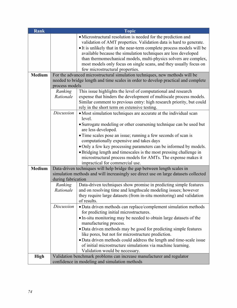
74
Rank Topic • Microstructural resolution is needed for the prediction and
validation of AMT properties. Validation data is hard to generate. • It is unlikely that in the near-term complete process models will be
available because the simulation techniques are less developed than thermomechanical models, multi-physics solvers are complex, most models only focus on single scans, and they usually focus on few microstructural properties.
Medium For the advanced microstructural simulation techniques, new methods will be needed to bridge length and time scales in order to develop practical and complete process models
Ranking Rationale
This issue highlights the level of computational and research expense that hinders the development of multiscale process models. Similar comment to previous entry: high research priority, but could rely in the short term on extensive testing.
Discussion • Most simulation techniques are accurate at the individual scan level.
• Surrogate modeling or other coarsening technique can be used but are less developed.
• Time scales pose an issue; running a few seconds of scan is computationally expensive and takes days
• Only a few key processing parameters can be informed by models. • Bridging length and timescales is the most pressing challenge in
microstructural process models for AMTs. The expense makes it impractical for commercial use.
Medium Data-driven techniques will help bridge the gap between length scales in simulation methods and will increasingly see direct use on large datasets collected during fabrication
Ranking Rationale
Data-driven techniques show promise in predicting simple features and on resolving time and lengthscale modeling issues; however they require large datasets (from in-situ monitoring) and validation of results.
Discussion • Data driven methods can replace/complement simulation methods for predicting initial microstructures.
• In-situ monitoring may be needed to obtain large datasets of the manufacturing process.
• Data driven methods may be good for predicting simple features like pores, but not for microstructure prediction.
• Data driven methods could address the length and time-scale issue of initial microstructure simulations via machine learning. Validation would be necessary.
High Validation benchmark problems can increase manufacturer and regulator confidence in modeling and simulation methods
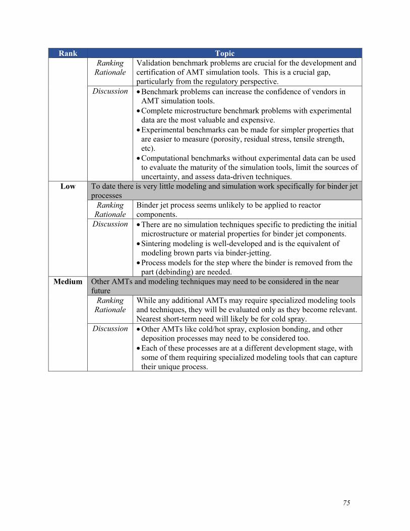
75
Rank Topic Ranking
Rationale Validation benchmark problems are crucial for the development and certification of AMT simulation tools. This is a crucial gap, particularly from the regulatory perspective.
Discussion • Benchmark problems can increase the confidence of vendors in AMT simulation tools.
• Complete microstructure benchmark problems with experimental data are the most valuable and expensive.
• Experimental benchmarks can be made for simpler properties that are easier to measure (porosity, residual stress, tensile strength, etc).
• Computational benchmarks without experimental data can be used to evaluate the maturity of the simulation tools, limit the sources of uncertainty, and assess data-driven techniques.
Low To date there is very little modeling and simulation work specifically for binder jet processes
Ranking Rationale
Binder jet process seems unlikely to be applied to reactor components.
Discussion • There are no simulation techniques specific to predicting the initial microstructure or material properties for binder jet components.
• Sintering modeling is well-developed and is the equivalent of modeling brown parts via binder-jetting.
• Process models for the step where the binder is removed from the part (debinding) are needed.
Medium Other AMTs and modeling techniques may need to be considered in the near future
Ranking Rationale
While any additional AMTs may require specialized modeling tools and techniques, they will be evaluated only as they become relevant. Nearest short-term need will likely be for cold spray.
Discussion • Other AMTs like cold/hot spray, explosion bonding, and other deposition processes may need to be considered too.
• Each of these processes are at a different development stage, with some of them requiring specialized modeling tools that can capture their unique process.


77
8 Conclusions This report summarizes the current state-of-the-art in predicting initial microstructures of material manufactured with AMTs using modeling and simulation. This survey attempts to encompass the current body of literature published on methods for predicting initial microstructures both for general materials and specific to AMTs. Included in this survey is a gap analysis describing the shortcomings of the various modeling and simulation methods identified and described in the report. To summarize briefly, limited modeling techniques linking specific single processing parameters to general, high level microstructural features are well-developed and fairly robust, even when applied to AMTs. However, complete process models taking a full description of all the relevant processing parameters to a complete description of the resulting microstructure are not yet available. Such modeling frameworks will need to be developed and validated for regulators to confidently rely on modeling and simulation predictions without extensive experimental characterization of the final material. Automated length- and time-scale bridging and methods for multiphysics coupling are key barriers to the development of such frameworks. However, as described in this report, much recent progress has been made.
This report is the first in a two-volume series. The second volume focuses on predicting key material properties starting from the initial AMT microstructure. Taken together then, the two volumes provide a comprehensive summary of modeling and simulation tools for predicting the properties of a material given only a description of the process and processing parameters.


79
ACKNOWLEDGEMENTS
This report was sponsored by the U.S. Nuclear Regulatory Commission (NRC) under agreement 31310019F0057 with the U.S. Department of Energy. The authors thank Dr. Shah Malik and Dr. Amy Hull of the NRC for their helpful feedback on the draft version of the report.


81
REFERENCES
[1] Nuclear Energy Institute, “Roadmap for Regulatory Acceptance of Advanced Manufacturing Methods in the Nuclear Energy Industry,” 2019.
[2] Subcommittee on Advanced Manufacturing, “Strategy for American Leadership in Advanced Manufacturing,” 2018. [Online]. Available: papers3://publication/uuid/C7139B46-00F5-4E25-B13D-9E4A05DCCE6E.
[3] R. W. Messler Jr., Principles of Welding. John Wiley & Sons, 1999. [4] J. Simpson et al., “Considerations for Application of Additive Manufacturing to Nuclear
Reactor Core Components,” 2019. [5] W. Jessup, S. Kinsey, S. Kauffman, W. Pollock, and C. Bagley, “United States Nuclear
Manufacturing Infrastructure Assessment,” 2018. [6] U.S. NRC, “Action Plan for Advanced Manufacturing Technologies (AMTs),” 2019. [7] D. Gandy, C. Stover, H. Xu, V. Pence, S. Lawler, and M. Cusworth, “Advanced
manufacturing to enable the next generation of nuclear plants,” in Proceedings of the 2018 International Congress on Advances in Nuclear Power Plants, ICAPP 2018, 2018.
[8] M. Song, M. Wang, X. Lou, R. B. Rebak, and G. S. Was, “Radiation damage and irradiation-assisted stress corrosion cracking of additively manufactured 316L stainless steels,” J. Nucl. Mater., 2019.
[9] R. B. Rebak and X. Lou, “Environmental Cracking and Irradiation Resistant Stainless Steels by Additive Manufacturing (NE0008428),” General Electric, Schenectady, NY (United States), Mar. 2018. doi: 10.2172/1431212.
[10] Y. Zhong et al., “Additive manufacturing of ITER first wall panel parts by two approaches: Selective laser melting and electron beam melting,” Fusion Eng. Des., vol. 116, pp. 24–33, 2017, http://dx.doi.org/10.1016/j.fusengdes.2017.01.032.
[11] Y. Zhong et al., “Additive manufacturing of 316L stainless steel by electron beam melting for nuclear fusion applications,” J. Nucl. Mater., vol. 486, pp. 234–245, 2017.
[12] Q. Huang, “Status and improvement of CLAM for nuclear application,” Nucl. Fusion, vol. 57, no. 8, 2017.
[13] Y. Jialin, “Selective laser melting additive manufacturing of advanced nuclear materials V-6Cr-6Ti,” Mater. Lett., vol. 209, pp. 268–271, 2017, https://doi.org/10.1016/j.matlet.2017.08.014.
[14] R. M. Clayton, “The use of elemental powder mixes in laser-based additive manufacturing,” Missouri University of Science and Technology, 2013.
[15] X. Lou, M. Song, P. W. Emigh, M. A. Othon, and P. L. Andresen, “On the stress corrosion crack growth behaviour in high temperature water of 316L stainless steel made by laser powder bed fusion additive manufacturing,” Corros. Sci., vol. 128, no. February, pp. 140–153, 2017, http://dx.doi.org/10.1016/j.corsci.2017.09.017.
[16] N. Sridharan, M. N. Gussev, and K. G. Field, “Performance of a ferritic/martensitic steel for nuclear reactor applications fabricated using additive manufacturing,” J. Nucl. Mater., vol. 521, pp. 45–55, 2019, https://doi.org/10.1016/j.jnucmat.2019.04.020.
[17] T. Abe and H. Sasahara, “Dissimilar metal deposition with a stainless steel and nickel-based alloy using wire and arc-based additive manufacturing,” Precis. Eng., vol. 45, pp. 387–395, 2016, http://dx.doi.org/10.1016/j.precisioneng.2016.03.016.
[18] B. Baufeld, R. Widdison, T. Dutilleul, and K. Bridger, “Electron Beam Additive Manufacturing at the Nuclear AMRC,” Electrotech. Electron., vol. 51, no. 5–6, pp. 25–30,
82
2016. [19] AMFG, “Enhancing Additive Manufacturing with Reverse Engineering, Autonomous
Manufacturing (AMFG),” 2018. https://amfg.ai/2018/05/10/enhancing-additive-manufacturing-with-reverse-engineering/.
[20] Nuclear Engineering International (NEI), “Printing nuclear parts,” Nuclear Engineering International, 2017. https://www.neimagazine.com/features/featureprinting-nuclear-parts-5861118/.
[21] Electric Power Research Institute (EPRI), “BWRVIP-84, Rev. 3, Guidelines for Selection and Use of Materials for Repairs to BWR Internal Components,” Palo Alto, California, 2018.
[22] V. Bhavar, P. Kattire, V. Patil, S. Khot, K. Gujar, and R. Singh, “A review on powder bed fusion technology of metal additive manufacturing,” in Additive Manufacturing Handbook: Product Development for the Defense Industry, 2017.
[23] D. Gu, Laser Additive Manufacturing of High-Performance Materials. Springer-Verlag Berlin Heidelberg, 2015.
[24] R. Udroiu, “Powder Bed Additive Nanufacturing Systems and Its Applications,” Acad. J. Manuf. Eng., 2012.
[25] T. Kellner, “The FAA Cleared the First 3D Printed Part to Fly in a Commercial Jet Engine from GE,” GE reports, 2015. https://www.ge.com/reports/post/116402870270/the-faa-cleared-the-first-3d-printed-part-to-fly-2/.
[26] A. Hull, C. Moyer, B. Harris, and J. Christensen, “Proceedings of the Public Meeting on Additive Manufacturing for Reactor Materials and Components,” 2019.
[27] G. Electric, “X Line 2000R,” GE additive, 2020. https://www.ge.com/additive/who-we-are/concept-laser.
[28] M. Zenou and L. Grainger, “Additive manufacturing of metallic materials,” in Additive Manufacturing: Materials Processes, Quantifications and Applications, 2018, pp. 53–103.
[29] Sciaky, “Metal Additive Manufacturing with EBAM® Technology,” Sciaky inc., 2020. https://www.sciaky.com/.
[30] A. Saboori, D. Gallo, S. Biamino, P. Fino, and M. Lombardi, “An overview of additive manufacturing of titanium components by directed energy deposition: Microstructure and mechanical properties,” Appl. Sci., vol. 7, no. 9, 2017.
[31] N. Shamsaei, A. Yadollahi, L. Bian, and S. M. Thompson, “An overview of Direct Laser Deposition for additive manufacturing; Part II: Mechanical behavior, process parameter optimization and control,” Additive Manufacturing. 2015, doi: 10.1016/j.addma.2015.07.002.
[32] S. M. Thompson, L. Bian, N. Shamsaei, and A. Yadollahi, “An overview of Direct Laser Deposition for additive manufacturing; Part I: Transport phenomena, modeling and diagnostics,” Addit. Manuf., vol. 8, pp. 36–62, 2015, http://dx.doi.org/10.1016/j.addma.2015.07.001.
[33] BeAM Machines, “BeAM Machines – Directed Energy Deposition,” 2020. https://www.beam-machines.com (accessed May 10, 2020).
[34] “Insstek website,” Insstek, 2016. http://www.insstek.com/. [35] M. Galati and L. Iuliano, “A literature review of powder-based electron beam melting
focusing on numerical simulations,” Addit. Manuf., vol. 19, pp. 1–20, 2018, http://dx.doi.org/10.1016/j.addma.2017.11.001.
[36] L. E. Murr et al., “Fabrication of metal and alloy components by additive manufacturing:
83
Examples of 3D materials science,” Journal of Materials Research and Technology. 2012, doi: 10.1016/S2238-7854(12)70009-1.
[37] Sciaky, “Benefits of Wire vs. Powder Metal 3D Printing,” Sciaky inc., 2020. https://www.sciaky.com/additive-manufacturing/wire-vs-powder.
[38] B. Baufeld, E. Brandl, and O. Van Der Biest, “Wire based additive layer manufacturing: Comparison of microstructure and mechanical properties of Ti-6Al-4V components fabricated by laser-beam deposition and shaped metal deposition,” J. Mater. Process. Technol., 2011.
[39] H. Schultz, Electon Beam Welding. Woodhead Publishing, 1993. [40] Sciaky, “Largest Metal 3D Printer Available | Industrial 3D Printing,” Sciaky inc., 2020.
https://www.sciaky.com/largest-metal-3d-printer-available (accessed Sep. 20, 2011). [41] B. Baufeld, T. Dutilleul, and K. Bridger, “Electron Beam Welding at the Nuclear AMRC,”
in 3rd International Electron Beam Welding Conference, 2015, pp. 1–7. [42] European Powder Metallurgy Association, “Introduction to PM HIP Technology,” 2013.
[Online]. Available: http://www.epma.com/pdfs/Final_HIP_Brochure_Low_res.pdf. [43] C. B. Boyer, “Historical review of HIP equipment,” in Hot Isostatic Pressing—Theory
and Applications, Springer, 1992, pp. 465–510. [44] C. Qiu, “Net-shape hot isostatic pressing of a nickel-based powder superalloy,” University
of Birmingham, 2010. [45] G. Raisson, J. Y. Guédou, D. Guichard, and J. M. Rongvaux, “Production of net-shape
static parts by direct HIPing of nickel base superalloy prealloyed powders,” Adv. Mater. Res., vol. 278, pp. 277–282, 2011.
[46] R. Baccino, F. Moret, F. Pellerin, D. Guichard, and G. Raisson, “High performance and high complexity net shape parts for gas turbines: The ISOPREC® powder metallurgy process,” Mater. Des., vol. 21, no. 4, pp. 345–350, 2000.
[47] L. KOBE STEEL, “Hot Isostatic Pressing (HIP) Equipment,” Kobelco. https://www.kobelco.co.jp/english/products/ip/product/hip/hip_01.html.
[48] Electric Power Research Institute (EPRI), “Advanced Technology for Large Scale (ATLAS) Powder Metallurgy–Hot Isostatic Pressing,” 2016.
[49] D. Gandy, J. Siefert, L. Lherbier, and D. Novotnak, “PM-HIP research for pressure retaining applications within the electric power industry,” in ASME 2014 Small Modular Reactors Symposium, SMR 2014, 2014, doi: 10.1115/SMR2014-3305.
[50] D. W. Gandy, “Factory Fabrication of Small Modular Reactor Vessel Assemblies Highlight Four Advanced Manufacturing,” in NRC Regulatory Information Conference (RIC): Use of Advanced Manufacturing Technology for Power Reactors, 2019.
[51] T. DebRoy et al., “Additive manufacturing of metallic components – Process, structure and properties,” Prog. Mater. Sci., vol. 92, pp. 112–224, 2018.
[52] M. Ziaee and N. B. Crane, “Binder jetting: A review of process, materials, and methods,” Additive Manufacturing. 2019, doi: 10.1016/j.addma.2019.05.031.
[53] A. Mostafaei, E. L. Stevens, E. T. Hughes, S. D. Biery, C. Hilla, and M. Chmielus, “Powder bed binder jet printed alloy 625: Densification, microstructure and mechanical properties,” Mater. Des., vol. 108, pp. 126–135, 2016, http://dx.doi.org/10.1016/j.matdes.2016.06.067.
[54] Alkaios Bournias Varotsis, “Introduction to Binder Jetting 3D printing,” 3D Hubs, 2020. https://www.3dhubs.com/knowledge-base/introduction-binder-jetting-3d-printing/.
[55] ExOne, “The X1 160PRO: Advanced Metal Binder Jetting For Sustainable, High-Quality
84
Production,” ExOne, 2020. https://www.exone.com/. [56] B. R. Maier, B. L. Garcia-Diaz, B. Hauch, L. C. Olson, R. L. Sindelar, and K. Sridharan,
“Cold spray deposition of Ti2AlC coatings for improved nuclear fuel cladding,” J. Nucl. Mater., 2015.
[57] R. Fernández, D. MacDonald, A. Nastić, B. Jodoin, A. Tieu, and M. Vijay, “Enhancement and Prediction of Adhesion Strength of Copper Cold Spray Coatings on Steel Substrates for Nuclear Fuel Repository,” J. Therm. Spray Technol., 2016.
[58] A. Simchi and H. Pohl, “Effects of laser sintering processing parameters on the microstructure and densification of iron powder,” Mater. Sci. Eng. A, vol. 359, no. 1–2, pp. 119–128, 2003.
[59] B. Zhang, H. Liao, and C. Coddet, “Effects of processing parameters on properties of selective laser melting Mg-9%Al powder mixture,” Mater. Des., vol. 34, pp. 753–758, 2012, http://dx.doi.org/10.1016/j.matdes.2011.06.061.
[60] P. Hanzl, M. Zetek, T. Bakša, and T. Kroupa, “The influence of processing parameters on the mechanical properties of SLM parts,” Procedia Eng., vol. 100, no. January, pp. 1405–1413, 2015, http://dx.doi.org/10.1016/j.proeng.2015.01.510.
[61] G. Kasperovich, J. Haubrich, J. Gussone, and G. Requena, “Correlation between porosity and processing parameters in TiAl6V4 produced by selective laser melting,” Mater. Des., vol. 105, pp. 160–170, 2016, http://dx.doi.org/10.1016/j.matdes.2016.05.070.
[62] K. Guan, Z. Wang, M. Gao, X. Li, and X. Zeng, “Effects of processing parameters on tensile properties of selective laser melted 304 stainless steel,” Mater. Des., vol. 50, pp. 581–586, 2013, http://dx.doi.org/10.1016/j.matdes.2013.03.056.
[63] U. F. Kocks, C. N. Tome, and H.-R. Wenk, Texture and Anisotropy. Cambridge University Press, 1998.
[64] T. Wang, Y. Y. Zhu, S. Q. Zhang, H. B. Tang, and H. M. Wang, “Grain morphology evolution behavior of titanium alloy components during laser melting deposition additive manufacturing,” J. Alloys Compd., vol. 632, pp. 505–513, 2015.
[65] V. A. Popovich, E. V. Borisov, A. A. Popovich, V. S. Sufiiarov, D. V. Masaylo, and L. Alzina, “Functionally graded Inconel 718 processed by additive manufacturing: Crystallographic texture, anisotropy of microstructure and mechanical properties,” Mater. Des., vol. 114, pp. 441–449, 2017.
[66] R. R. Dehoff et al., “Site specific control of crystallographic grain orientation through electron beam additive manufacturing,” Mater. Sci. Technol. (United Kingdom), vol. 31, no. 8, pp. 931–938, 2015.
[67] K. Hagihara, T. Nakano, M. Suzuki, T. Ishimoto, Suyalatu, and S. H. Sun, “Successful additive manufacturing of MoSi2including crystallographic texture and shape control,” J. Alloys Compd., vol. 696, pp. 67–72, 2017, http://dx.doi.org/10.1016/j.jallcom.2016.11.191.
[68] J. Liu and A. C. To, “Quantitative texture prediction of epitaxial columnar grains in additive manufacturing using selective laser melting,” Addit. Manuf., vol. 16, pp. 58–64, 2017, http://dx.doi.org/10.1016/j.addma.2017.05.005.
[69] J. Gockel, J. Beuth, and K. Taminger, “Integrated control of solidification microstructure and melt pool dimensions in electron beam wire feed additive manufacturing of ti-6al-4v,” Addit. Manuf., vol. 1, pp. 119–126, 2014, http://dx.doi.org/10.1016/j.addma.2014.09.004.
[70] N. Raghavan et al., “Numerical modeling of heat-transfer and the influence of process parameters on tailoring the grain morphology of IN718 in electron beam additive
85
manufacturing,” Acta Mater., vol. 112, pp. 303–314, 2016, http://dx.doi.org/10.1016/j.actamat.2016.03.063.
[71] Y. Zhu, X. Tian, J. Li, and H. Wang, “The anisotropy of laser melting deposition additive manufacturing Ti-6.5Al-3.5Mo-1.5Zr-0.3Si titanium alloy,” Mater. Des., vol. 67, pp. 538–542, 2015.
[72] F. Cao, T. Zhang, M. A. Ryder, and D. A. Lados, “A Review of the Fatigue Properties of Additively Manufactured Ti-6Al-4V,” Jom, vol. 70, no. 3, pp. 349–357, 2018, https://doi.org/10.1007/s11837-017-2728-5.
[73] L. Sheridan, O. E. Scott-Emuakpor, T. George, and J. E. Gockel, “Relating porosity to fatigue failure in additively manufactured alloy 718,” Mater. Sci. Eng. A, vol. 727, no. April, pp. 170–176, 2018, https://doi.org/10.1016/j.msea.2018.04.075.
[74] S. Tammas-Williams, P. J. Withers, I. Todd, and P. B. Prangnell, “The Influence of Porosity on Fatigue Crack Initiation in Additively Manufactured Titanium Components,” Sci. Rep., vol. 7, no. 1, pp. 1–13, 2017, http://dx.doi.org/10.1038/s41598-017-06504-5.
[75] P. Li, D. H. Warner, A. Fatemi, and N. Phan, “Critical assessment of the fatigue performance of additively manufactured Ti-6Al-4V and perspective for future research,” Int. J. Fatigue, vol. 85, pp. 130–143, 2016.
[76] A. J. Sterling, B. Torries, N. Shamsaei, S. M. Thompson, and D. W. Seely, “Fatigue behavior and failure mechanisms of direct laser deposited Ti-6Al-4V,” Mater. Sci. Eng. A, vol. 655, pp. 100–112, 2016, http://dx.doi.org/10.1016/j.msea.2015.12.026.
[77] C. Brice, R. Shenoy, M. Kral, and K. Buchannan, “Precipitation behavior of aluminum alloy 2139 fabricated using additive manufacturing,” Mater. Sci. Eng. A, vol. 648, pp. 9–14, 2015, http://dx.doi.org/10.1016/j.msea.2015.08.088.
[78] M. Ni et al., “Anisotropic tensile behavior of in situ precipitation strengthened Inconel 718 fabricated by additive manufacturing,” Mater. Sci. Eng. A, vol. 701, no. April, pp. 344–351, 2017, http://dx.doi.org/10.1016/j.msea.2017.06.098.
[79] H. Xiao et al., “Effects of laser modes on Nb segregation and Laves phase formation during laser additive manufacturing of nickel-based superalloy,” Mater. Lett., vol. 188, no. August 2016, pp. 260–262, 2017.
[80] L. D. Bobbio et al., “Additive manufacturing of a functionally graded material from Ti-6Al-4V to Invar: Experimental characterization and thermodynamic calculations,” Acta Mater., vol. 127, pp. 133–142, 2017, http://dx.doi.org/10.1016/j.actamat.2016.12.070.
[81] A. Reichardt et al., “Development and characterization of Ti-6Al-4V to 304L stainless steel gradient components fabricated with laser deposition additive manufacturing,” Mater. Des., vol. 104, pp. 404–413, 2016, http://dx.doi.org/10.1016/j.matdes.2016.05.016.
[82] M. Tang and P. C. Pistorius, “Oxides, porosity and fatigue performance of AlSi10Mg parts produced by selective laser melting,” Int. J. Fatigue, vol. 94, pp. 192–201, 2017, http://dx.doi.org/10.1016/j.ijfatigue.2016.06.002.
[83] M. A. S. Torres and H. J. C. Voorwald, “An evaluation of shot peening, residual stress and stress relaxation on the fatigue life of AISI 4340 steel,” Int. J. Fatigue, vol. 24, no. 8, pp. 877–886, 2002.
[84] A. S. Wu, D. W. Brown, M. Kumar, G. F. Gallegos, and W. E. King, “An Experimental Investigation into Additive Manufacturing-Induced Residual Stresses in 316L Stainless Steel,” Metall. Mater. Trans. A Phys. Metall. Mater. Sci., vol. 45, no. 13, pp. 6260–6270, 2014.
[85] P. Vora, K. Mumtaz, I. Todd, and N. Hopkinson, “AlSi12 in-situ alloy formation and
86
residual stress reduction using anchorless selective laser melting,” Addit. Manuf., vol. 7, pp. 12–19, 2015, http://dx.doi.org/10.1016/j.addma.2015.06.003.
[86] C. Li, Z. Y. Liu, X. Y. Fang, and Y. B. Guo, “Residual Stress in Metal Additive Manufacturing,” Procedia CIRP, vol. 71, pp. 348–353, 2018.
[87] D. Greitemeier, C. Dalle Donne, F. Syassen, J. Eufinger, and T. Melz, “Effect of surface roughness on fatigue performance of additive manufactured Ti–6Al–4V,” Mater. Sci. Technol. (United Kingdom), vol. 32, no. 7, pp. 629–634, 2016.
[88] G. Pyka et al., “Surface modification of Ti6Al4V open porous structures produced by additive manufacturing,” Adv. Eng. Mater., vol. 14, no. 6, pp. 363–370, 2012.
[89] C. de Formanoir, M. Suard, R. Dendievel, G. Martin, and S. Godet, “Improving the mechanical efficiency of electron beam melted titanium lattice structures by chemical etching,” Addit. Manuf., vol. 11, pp. 71–76, 2016, http://dx.doi.org/10.1016/j.addma.2016.05.001.
[90] A. Yadollahi and N. Shamsaei, “Additive manufacturing of fatigue resistant materials: Challenges and opportunities,” Int. J. Fatigue, vol. 98, pp. 14–31, 2017, http://dx.doi.org/10.1016/j.ijfatigue.2017.01.001.
[91] M. M. Schwartz, Modern Metal Joining Techniques. John Wiley & Sons, 1969. [92] F. Trevisan et al., “On the selective laser melting (SLM) of the AlSi10Mg alloy: Process,
microstructure, and mechanical properties,” Materials. 2017, doi: 10.3390/ma10010076. [93] H. Hu et al., “Mathematical modelling of solidification and melting : a review,” Model.
Simul. Mater. Sci. Eng., vol. 4, p. 371, 1996. [94] W. Kurz, B. Giovanola, and R. Trivedi, “Theory of microstructural development during
rapid solidification,” Acta Metall., vol. 34, no. 5, pp. 823–830, 1986. [95] T. Niendorf, S. Leuders, A. Riemer, H. A. Richard, T. Tröster, and D. Schwarze, “Highly
anisotropic steel processed by selective laser melting,” Metall. Mater. Trans. B Process Metall. Mater. Process. Sci., vol. 44, no. 4, pp. 794–796, 2013.
[96] P. Kanagarajah, F. Brenne, T. Niendorf, and H. J. Maier, “Inconel 939 processed by selective laser melting: Effect of microstructure and temperature on the mechanical properties under static and cyclic loading,” Mater. Sci. Eng. A, vol. 588, pp. 188–195, 2013, http://dx.doi.org/10.1016/j.msea.2013.09.025.
[97] K. Kunze, T. Etter, J. Grässlin, and V. Shklover, “Texture, anisotropy in microstructure and mechanical properties of IN738LC alloy processed by selective laser melting (SLM),” Mater. Sci. Eng. A, vol. 620, pp. 213–222, 2015, http://dx.doi.org/10.1016/j.msea.2014.10.003.
[98] G. P. Dinda, A. K. Dasgupta, and J. Mazumder, “Texture control during laser deposition of nickel-based superalloy,” Scr. Mater., vol. 67, no. 5, pp. 503–506, 2012, http://dx.doi.org/10.1016/j.scriptamat.2012.06.014.
[99] G. P. Dinda, A. K. Dasgupta, and J. Mazumder, “Evolution of microstructure in laser deposited Al-11.28%Si alloy,” Surf. Coatings Technol., vol. 206, no. 8–9, pp. 2152–2160, 2012, http://dx.doi.org/10.1016/j.surfcoat.2011.09.051.
[100] A. Yadollahi, N. Shamsaei, S. M. Thompson, and D. W. Seely, “Effects of process time interval and heat treatment on the mechanical and microstructural properties of direct laser deposited 316L stainless steel,” Mater. Sci. Eng. A, vol. 644, pp. 171–183, 2015, http://dx.doi.org/10.1016/j.msea.2015.07.056.
[101] K. Masubuchi, Analysis of welded structures: residual stresses, distortion, and their consequences, vol. 33. Elsevier, 2013.
87
[102] O. Fergani, F. Berto, T. Welo, and S. Y. Liang, “Analytical modelling of residual stress in additive manufacturing,” Fatigue Fract. Eng. Mater. Struct., vol. 40, no. 6, pp. 971–978, 2017.
[103] Y. Chew, J. H. L. Pang, G. Bi, and B. Song, “Thermo-mechanical model for simulating laser cladding induced residual stresses with single and multiple clad beads,” J. Mater. Process. Technol., vol. 224, pp. 89–101, 2015, http://dx.doi.org/10.1016/j.jmatprotec.2015.04.031.
[104] T. Mukherjee, W. Zhang, and T. DebRoy, “An improved prediction of residual stresses and distortion in additive manufacturing,” Comput. Mater. Sci., vol. 126, pp. 360–372, 2017, http://dx.doi.org/10.1016/j.commatsci.2016.10.003.
[105] A. M. Philo et al., “A pragmatic continuum level model for the prediction of the onset of keyholing in laser powder bed fusion,” Int. J. Adv. Manuf. Technol., vol. 101, no. 1–4, pp. 697–714, 2019.
[106] W. E. King et al., “Observation of keyhole-mode laser melting in laser powder-bed fusion additive manufacturing,” J. Mater. Process. Technol., vol. 214, no. 12, pp. 2915–2925, 2014, http://dx.doi.org/10.1016/j.jmatprotec.2014.06.005.
[107] J. Y. Lee, S. H. Ko, D. F. Farson, and C. D. Yoo, “Mechanism of keyhole formation and stability in stationary laser welding,” J. Phys. D. Appl. Phys., vol. 35, no. 13, pp. 1570–1576, 2002.
[108] J. Svenungsson, I. Choquet, and A. F. H. Kaplan, “Laser Welding Process - A Review of Keyhole Welding Modelling,” Phys. Procedia, vol. 78, no. August, pp. 182–191, 2015, http://dx.doi.org/10.1016/j.phpro.2015.11.042.
[109] T. Mukherjee, V. Manvatkar, A. De, and T. DebRoy, “Dimensionless numbers in additive manufacturing,” J. Appl. Phys., vol. 121, no. 6, 2017.
[110] J. Elmer, P. W. Hochanadel, K. Lachenberg, C. Caristan, and T. Webber, “Introduction to High Energy Density Electron and Laser Beam Welding,” 2011.
[111] A. Matsunawa, J.-D. Kim, N. Seto, M. Mizutani, and S. Katayama, “Dynamics of keyhole and molten pool in laser welding,” J. Laser Appl., 1998.
[112] T. Mukherjee, J. S. Zuback, A. De, and T. DebRoy, “Printability of alloys for additive manufacturing,” Sci. Rep., vol. 6, pp. 1–8, 2016.
[113] L. N. Carter, C. Martin, P. J. Withers, and M. M. Attallah, “The influence of the laser scan strategy on grain structure and cracking behaviour in SLM powder-bed fabricated nickel superalloy,” J. Alloys Compd., vol. 615, pp. 338–347, 2014, http://dx.doi.org/10.1016/j.jallcom.2014.06.172.
[114] L. Thijs, F. Verhaeghe, T. Craeghs, J. Van Humbeeck, and J. P. Kruth, “A study of the microstructural evolution during selective laser melting of Ti-6Al-4V,” Acta Mater., vol. 58, no. 9, pp. 3303–3312, 2010, http://dx.doi.org/10.1016/j.actamat.2010.02.004.
[115] Y. J. Liang and H. M. Wang, “Origin of stray-grain formation and epitaxy loss at substrate during laser surface remelting of single-crystal nickel-base superalloys,” Mater. Des., vol. 102, pp. 297–302, 2016, http://dx.doi.org/10.1016/j.matdes.2016.04.051.
[116] S. Das, “Physical Aspects of Process Control in Selective Laser Sintering of Metals,” Adv. Eng. Mater., vol. 5, no. 10, pp. 701–711, 2003.
[117] M. Garibaldi, I. Ashcroft, M. Simonelli, and R. Hague, “Metallurgy of high-silicon steel parts produced using Selective Laser Melting,” Acta Mater., vol. 110, pp. 207–216, 2016, http://dx.doi.org/10.1016/j.actamat.2016.03.037.
[118] A. A. Antonysamy, J. Meyer, and P. B. Prangnell, “Effect of build geometry on the β-
88
grain structure and texture in additive manufacture of Ti6Al4V by selective electron beam melting,” Mater. Charact., vol. 84, pp. 153–168, 2013, http://dx.doi.org/10.1016/j.matchar.2013.07.012.
[119] J. Delgado, J. Ciurana, and C. A. Rodríguez, “Influence of process parameters on part quality and mechanical properties for DMLS and SLM with iron-based materials,” Int. J. Adv. Manuf. Technol., vol. 60, no. 5–8, pp. 601–610, 2012.
[120] E. Malekipour and H. El-Mounayri, “Common defects and contributing parameters in powder bed fusion AM process and their classification for online monitoring and control: a review,” Int. J. Adv. Manuf. Technol., vol. 95, no. 1–4, pp. 527–550, 2018.
[121] M. Sadowski, L. Ladani, W. Brindley, and J. Romano, “Optimizing quality of additively manufactured Inconel 718 using powder bed laser melting process,” Addit. Manuf., vol. 11, pp. 60–70, 2016, http://dx.doi.org/10.1016/j.addma.2016.03.006.
[122] C. L. A. Leung, S. Marussi, M. Towrie, R. C. Atwood, P. J. Withers, and P. D. Lee, “The effect of powder oxidation on defect formation in laser additive manufacturing,” Acta Mater., vol. 166, pp. 294–305, 2019, https://doi.org/10.1016/j.actamat.2018.12.027.
[123] J. A. Slotwinski, E. J. Garboczi, P. E. Stutzman, C. F. Ferraris, S. S. Watson, and M. A. Peltz, “Characterization of metal powders used for additive manufacturing,” J. Res. Natl. Inst. Stand. Technol., vol. 119, pp. 460–493, 2014.
[124] H. P. Tang, M. Qian, N. Liu, X. Z. Zhang, G. Y. Yang, and J. Wang, “Effect of Powder Reuse Times on Additive Manufacturing of Ti-6Al-4V by Selective Electron Beam Melting,” JOM, vol. 67, no. 3, pp. 555–563, 2015.
[125] B. Sartin et al., “316L Powder Reuse for Metal Additive Manufacturing,” in Solid Freeform Fabrication 2017: Proceedings of the 28th Annual International Solid, 2017, pp. 351–364.
[126] F. Del Re et al., “Statistical approach for assessing the effect of powder reuse on the final quality of AlSi10Mg parts produced by laser powder bed fusion additive manufacturing,” Int. J. Adv. Manuf. Technol., vol. 97, no. 5–8, pp. 2231–2240, 2018.
[127] O. A. Quintana, J. Alvarez, R. Mcmillan, W. Tong, and C. Tomonto, “Effects of Reusing Ti-6Al-4V Powder in a Selective Laser Melting Additive System Operated in an Industrial Setting,” JOM, vol. 70, no. 9, pp. 1863–1869, 2018, https://doi.org/10.1007/s11837-018-3011-0.
[128] B. Liu, R. Wildman, C. Tuck, I. Ashcroft, and R. Hague, “Investigaztion the effect of particle size distribution on processing parameters optimisation in selective laser melting process,” in 22nd Annual International Solid Freeform Fabrication Symposium - An Additive Manufacturing Conference, SFF 2011, 2011, pp. 227–238.
[129] A. J. Pinkerton and L. Li, “Direct additive laser manufacturing using gas- and water-atomised H13 tool steel powders,” Int. J. Adv. Manuf. Technol., vol. 25, no. 5–6, pp. 471–479, 2005.
[130] K. Darvish, Z. W. Chen, and T. Pasang, “Reducing lack of fusion during selective laser melting of CoCrMo alloy: Effect of laser power on geometrical features of tracks,” Mater. Des., vol. 112, pp. 357–366, 2016, http://dx.doi.org/10.1016/j.matdes.2016.09.086.
[131] S. Rahmati and E. Vahabli, “Evaluation of analytical modeling for improvement of surface roughness of FDM test part using measurement results,” Int. J. Adv. Manuf. Technol., vol. 79, no. 5–8, pp. 823–829, 2015.
[132] W. J. Sames, F. A. List, S. Pannala, R. R. Dehoff, and S. S. Babu, “The metallurgy and processing science of metal additive manufacturing,” Int. Mater. Rev., vol. 61, no. 5, pp.
89
315–360, 2016. [133] W. U. H. Syed, A. J. Pinkerton, and L. Li, “Combining wire and coaxial powder feeding
in laser direct metal deposition for rapid prototyping,” Appl. Surf. Sci., vol. 252, no. 13 SPEC. ISS., pp. 4803–4808, 2006.
[134] A. Rubenchik, S. Wu, S. Mitchell, I. Golosker, M. LeBlanc, and N. Peterson, “Direct measurements of temperature-dependent laser absorptivity of metal powders,” Appl. Opt., vol. 54, no. 24, p. 7230, 2015.
[135] C. D. Boley, S. C. Mitchell, A. M. Rubenchik, and S. S. Q. Wu, “Metal powder absorptivity: modeling and experiment,” Appl. Opt., vol. 55, no. 23, p. 6496, 2016.
[136] X. J. Wang, L. C. Zhang, M. H. Fang, and T. B. Sercombe, “The effect of atmosphere on the structure and properties of a selective laser melted Al-12Si alloy,” Mater. Sci. Eng. A, vol. 597, pp. 370–375, 2014, http://dx.doi.org/10.1016/j.msea.2014.01.012.
[137] M. S. Wȩglowski, S. Błacha, and A. Phillips, “Electron beam welding - Techniques and trends - Review,” Vacuum, vol. 130, pp. 72–92, 2016.
[138] SECO Warwick, Heat Treating Data Book, vol. 1. 2011. [139] S. Malarvizhi, K. Raghukandan, and N. Viswanathan, “Investigations on the influence of
post weld heat treatment on fatigue crack growth behaviour of electron beam welded AA2219 alloy,” Int. J. Fatigue, vol. 30, no. 9, pp. 1543–1555, 2008.
[140] G. Thomas, V. Ramachandra, R. Ganeshan, and R. Vasudevan, “Effect of pre- and post-weld heat treatments on the mechanical properties of electron beam welded Ti-6Al-4V alloy,” J. Mater. Sci., vol. 28, no. 18, pp. 4892–4899, 1993.
[141] K. A. Venkata, S. Kumar, H. C. Dey, D. J. Smith, P. J. Bouchard, and C. E. Truman, “Study on the effect of post weld heat treatment parameters on the relaxation of welding residual stresses in electron beam welded P91 steel plates,” Procedia Eng., vol. 86, no. Grade 91, pp. 223–233, 2014, http://dx.doi.org/10.1016/j.proeng.2014.11.032.
[142] C. C. Huang and T. H. Chuang, “Effects of post-weld heat treatments on the residual stress and mechanical properties of laser beam welded SAE 4130 steel plates,” Mater. Manuf. Process., vol. 12, no. 5, pp. 779–797, 1997.
[143] P. Krakhmalev, I. Yadroitsava, G. Fredriksson, and I. Yadroitsev, “In situ heat treatment in selective laser melted martensitic AISI 420 stainless steels,” Mater. Des., vol. 87, pp. 380–385, 2015, http://dx.doi.org/10.1016/j.matdes.2015.08.045.
[144] W. J. Sames et al., “Feasibility of in situ controlled heat treatment (ISHT) of Inconel 718 during electron beam melting additive manufacturing,” Addit. Manuf., vol. 13, pp. 156–165, 2017, http://dx.doi.org/10.1016/j.addma.2016.09.001.
[145] Y. Zhai, H. Galarraga, and D. A. Lados, “Microstructure Evolution, Tensile Properties, and Fatigue Damage Mechanisms in Ti-6Al-4V Alloys Fabricated by Two Additive Manufacturing Techniques,” Procedia Eng., vol. 114, pp. 658–666, 2015, http://dx.doi.org/10.1016/j.proeng.2015.08.007.
[146] D. Greitemeier, F. Palm, F. Syassen, and T. Melz, “Fatigue performance of additive manufactured TiAl6V4 using electron and laser beam melting,” Int. J. Fatigue, vol. 94, pp. 211–217, 2017, http://dx.doi.org/10.1016/j.ijfatigue.2016.05.001.
[147] M. Qian, W. Xu, M. Brandt, and H. P. Tang, “Additive manufacturing and postprocessing of Ti-6Al-4V for superior mechanical properties,” MRS Bull., vol. 41, no. 10, pp. 775–783, 2016.
[148] H. D. Carlton, K. D. Klein, and J. W. Elmer, “Evolution of microstructure and mechanical properties of selective laser melted Ti-5Al-5V-5Mo-3Cr after heat treatments,” Sci.

90
Technol. Weld. Join., vol. 24, no. 5, pp. 465–473, 2019. [149] C. Vargas, T. I. El-Wardany, M. A. Klecka, M. Grow, and T. B. Kashyap, “Repair of
Components using Additive Manufacturing with in-situ Cold Working,” 15/801,943, 2017.
[150] J. R. Hawkes, J. C. Rampone, T. I. El-Wardany, R. P. Salva, P. L. Clavette, and T. J. Garosshen, “Deep rolling tool and method,” 15/385,660, 2016.
[151] L. Hackel, J. R. Rankin, A. Rubenchik, W. E. King, and M. Matthews, “Laser peening: A tool for additive manufacturing post-processing,” Addit. Manuf., vol. 24, no. September, pp. 67–75, 2018, https://doi.org/10.1016/j.addma.2018.09.013.
[152] W. Guo et al., “Laser shock peening of laser additive manufactured Ti6Al4V titanium alloy,” Surf. Coatings Technol., vol. 349, no. May, pp. 503–510, 2018.
[153] H. Masuo et al., “Effects of Defects, Surface Roughness and HIP on Fatigue Strength of Ti-6Al-4V manufactured by Additive Manufacturing,” Procedia Struct. Integr., vol. 7, pp. 19–26, 2017.
[154] A. Isaev, V. Grechishnikov, P. Pivkin, K. Mihail, Y. Ilyuhin, and A. Vorotnikov, “Machining of Thin-walled Parts Produced by Additive Manufacturing Technologies,” Procedia CIRP, vol. 41, pp. 1023–1026, 2016, http://dx.doi.org/10.1016/j.procir.2015.08.088.
[155] C. Chen et al., “Effect of hot isostatic pressing (HIP) on microstructure and mechanical properties of Ti6Al4V alloy fabricated by cold spray additive manufacturing,” Addit. Manuf., vol. 27, no. March, pp. 595–605, 2019, https://doi.org/10.1016/j.addma.2019.03.028.
[156] F. H. Froes and B. Dutta, “The additive manufacturing (AM) of titanium alloys,” Adv. Mater. Res., vol. 1019, pp. 19–25, 2014.
[157] A. Mohammadhosseini, S. H. Masood, D. Fraser, and M. Jahedi, “Mechanical properties investigation of HIP and as-built EBM parts,” Adv. Mater. Res., vol. 576, pp. 216–219, 2012.
[158] M. Król and T. Taski, “Surface quality research for selective laser melting of TI-6AL-4V alloy,” Arch. Metall. Mater., vol. 61, no. 3, pp. 945–950, 2016.
[159] C. P. Ma, Y. C. Guan, and W. Zhou, “Laser polishing of additive manufactured Ti alloys,” Opt. Lasers Eng., vol. 93, no. February, pp. 171–177, 2017.
[160] P. J. Haagensen and S. J. Maddox, “IIW Recommendations on Post Weld Improvement of Steel and Aluminium,” 2003. [Online]. Available: http://www.weldonsweden.se/userfiles/file/IWSD1011-HiST/IWSD1011-HiST-M6/M6_4-XIII-1815-00 18 Aug 2006.pdf.
[161] E. Lyczkowska, P. Szymczyk, B. Dybała, and E. Chlebus, “Chemical polishing of scaffolds made of Ti-6Al-7Nb alloy by additive manufacturing,” Arch. Civ. Mech. Eng., vol. 14, no. 4, pp. 586–594, 2014.
[162] H. V. Atkinson and S. Davies, “Fundamental aspects of hot isostatic pressing: An overview,” Metall. Mater. Trans. A Phys. Metall. Mater. Sci., vol. 31, no. 12, pp. 2981–3000, 2000.
[163] E. A. Olevsky, “Theory of sintering: From discrete to continuum,” Mater. Sci. Eng. R Reports, vol. 23, no. 2, pp. 41–100, 1998.
[164] E. Klar, Powder Metallurgy: Applications, Advantages, and Limitations. Metals Park, Ohio: American Society for Metals, 1983.
[165] F. W. Crossman and M. F. Ashby, “The non-uniform flow of polycrystals by grain-
91
boundary sliding accommodated by power-law creep,” Acta Metall., vol. 23, no. 4, pp. 425–440, 1975.
[166] D. S. Wilkinson and M. F. Ashby, “Pressure sintering by power law creep,” Acta Metall., vol. 23, no. 11, pp. 1277–1285, 1975.
[167] H. J. Frost and M. F. Ashby, Deformation-Mechanism Maps: The Plasticity and Creep of Metals and Ceramics. Pergamon Press, 1982.
[168] H. D. Hanes, D. A. Seifert, and C. R. Watts, “Hot Isostatic Pressing,” 1977. [169] F. J. Humphreys and M. Hatherly, Recrystallization and Related Annealing Phenomena.
Oxford, U.K.: Elsevier Science Ltd, 1995. [170] M. Basaran, T. Z. Kattamis, R. Mehrabian, and M. C. Flemings, “The effect of
homogenization treatment and hot isostatic pressing on microporosity in cast steel,” Metall. Trans., vol. 4, no. 10, pp. 2429–2434, 1973.
[171] R. D. Doherty et al., “Current issues in recrystallization: a review,” Mater. Sci. Eng. A, vol. 238, no. 2, pp. 219–274, 1997.
[172] J. L. Urai, W. D. Means, and G. S. Lister, “Dynamic recrystallization of minerals,” Miner. rock Deform. Lab. Stud., vol. 36, pp. 161–199, 1996.
[173] M. R. Drury and J. L. Urai, “Deformation-related recrystallization processes,” Tectonophysics, vol. 172, no. 3–4, pp. 235–253, 1990.
[174] H. Mecking and U. F. Kocks, “A Mechanism for Static and Dynamic Recovery,” in Proceedings of the 5th International Conference on the Strength of Metals and Alloys, 1979, pp. 345–350.
[175] O. Guillon et al., “Field-assisted sintering technology/spark plasma sintering: Mechanisms, materials, and technology developments,” Adv. Eng. Mater., vol. 16, no. 7, pp. 830–849, 2014.
[176] A. Mostafaei et al., “Microstructural evolution and magnetic properties of binder jet additive manufactured Ni-Mn-Ga magnetic shape memory alloy foam,” Acta Mater., vol. 131, pp. 482–490, 2017, http://dx.doi.org/10.1016/j.actamat.2017.04.010.
[177] A. Mostafaei, P. Rodriguez De Vecchis, E. L. Stevens, and M. Chmielus, “Sintering regimes and resulting microstructure and properties of binder jet 3D printed Ni-Mn-Ga magnetic shape memory alloys,” Acta Mater., vol. 154, pp. 355–364, 2018, https://doi.org/10.1016/j.actamat.2018.05.047.
[178] S. G. Huang, K. Vanmeensel, L. Li, O. Van der Biest, and J. Vleugels, “Influence of starting powder on the microstructure of WC-Co hardmetals obtained by spark plasma sintering,” Mater. Sci. Eng. A, vol. 475, no. 1–2, pp. 87–91, 2008.
[179] M. K. Mani, G. Viola, M. J. Reece, J. P. Hall, and S. L. Evans, “Structural and magnetic characterization of spark plasma sintered Fe-50Co alloys,” Mater. Res. Soc. Symp. Proc, vol. 1516, pp. 201–207, 2012.
[180] Y. Li, H. Katsui, and T. Goto, “Consolidation of titanium carbide with zirconium carbide by spark plasma sintering,” Key Eng. Mater., vol. 616, pp. 52–55, 2014.
[181] Y. Li, H. Katsui, and T. Goto, “Spark plasma sintering of TiC-ZrC composites,” Ceram. Int., vol. 41, no. 5, pp. 7103–7108, 2015, http://dx.doi.org/10.1016/j.ceramint.2015.02.019.
[182] M. Tokita, “Recent and future progress on advanced ceramics sintering by Spark Plasma Sintering,” Nanotechnologies Russ., vol. 10, no. 3–4, pp. 261–267, 2015.
[183] Z. A. Munir, D. V. Quach, and M. Ohyanagi, “Electric Field and Current Effects on Sintering,” in Sintering: Mechanism of Convention Nanodensification and Field Assisted

92
Process, vol. 35, R. H. R. Castro and K. van Benthem, Eds. 2013, pp. 137–158. [184] U. Anselmi-Tamburini, G. Spinolo, F. Maglia, I. Tredici, T. B. Holland, and A. K.
Mukherjee, Field Assisted Sintering Mechanisms, vol. 35. 2013. [185] H. R. Piehler and D. P. DeLo, “Physical modeling of powder consolidation processes,”
Prog. Mater. Sci., vol. 42, no. 1–4, pp. 263–276, 1997. [186] S. V. Nair and J. K. Tien, “Densification Mechanism Maps for Hot Isostatic Pressing
(HIP) of Unequal Sized Particles.,” Metall. Trans. A, Phys. Metall. Mater. Sci., vol. 18 A, no. 1, pp. 97–107, 1987.
[187] E. K. H. Li and P. D. Funkenbusch, “Modeling of the densification rates of monosized and bimodal-sized particle systems during hot isostatic pressing (HIP),” Acta Metall., vol. 37, no. 6, pp. 1645–1655, 1989.
[188] B. K. Lograsso and D. A. Koss, “Densification modeling of titanium alloy powder during hot isostatic pressing,” Metall. Trans. A, vol. 19A, pp. 1767–1773, 1988.
[189] D. You, Y. Wang, C. Yang, and F. Li, “Comparative analysis of the hot-isostatic-pressing densification behavior of atomized and milled Ti6Al4V powders,” J. Mater. Res. Technol., 2020.
[190] J. W. McMurray, J. O. Kiggans, G. W. Helmreich, and K. A. Terrani, “Production of near-full density uranium nitride microspheres with a hot isostatic press,” J. Am. Ceram. Soc., vol. 101, no. 10, pp. 4492–4497, 2018.
[191] T. Do, T. J. Bauder, H. Suen, K. Rego, J. Yeom, and P. Kwon, “Additively Manufactured Full-Density Stainless Steel 316L With Binder Jet Printing,” in Proceedings of the ASME 2018 13th International Manufacturing Science and Engineering Conference. Volume 1: Additive Manufacturing; Bio and Sustainable Manufacturing, Jun. 2018, p. V001T01A017, doi: 10.1115/MSEC2018-6681.
[192] W. Du, X. Ren, C. Ma, and Z. Pei, “Binder Jetting Additive Manufacturing of Ceramics: A Literature Review,” in Proceedings of the ASME 2017 International Mechanical Engineering Congress and Exposition. Volume 14: Emerging Technologies; Materials: Genetics to Structures; Safety Engineering and Risk Analysis, Nov. 2017, p. V014T07A006, doi: 10.1115/IMECE2017-70344.
[193] P. Nandwana, A. M. Elliott, D. Siddel, A. Merriman, W. H. Peter, and S. S. Babu, “Powder bed binder jet 3D printing of Inconel 718: Densification, microstructural evolution and challenges,” Curr. Opin. Solid State Mater. Sci., vol. 21, no. 4, pp. 207–218, 2017, http://dx.doi.org/10.1016/j.cossms.2016.12.002.
[194] P. J. Withers and H. K. D. H. Bhadeshia, “Residual stress part 2 - Nature and origins,” Materials Science and Technology. 2001, doi: 10.1179/026708301101510087.
[195] A. Anca, A. Cardona, J. Risso, and V. D. Fachinotti, “Finite element modeling of welding processes,” Appl. Math. Model., 2011.
[196] K. Carpenter and A. Tabei, “On Residual Stress Development, Prevention, and Compensation in Metal Additive Manufacturing,” Materials (Basel)., vol. 13, no. 2, p. 255, Jan. 2020, https://www.mdpi.com/1996-1944/13/2/255.
[197] F. Hajializadeh and A. Ince, “Short review on modeling approaches for metal additive manufacturing process,” Mater. Des. Process. Commun., 2019, https://onlinelibrary.wiley.com/doi/abs/10.1002/mdp2.56.
[198] Y. Ueda and M. G. Yuan, “Prediction of residual stresses in butt welded plates using inherent strains,” J. Eng. Mater. Technol. Trans. ASME, 1993.
[199] D. Deng, H. Murakawa, and W. Liang, “Numerical simulation of welding distortion in
93
large structures,” Comput. Methods Appl. Mech. Eng., 2007. [200] I. Setien, M. Chiumenti, S. van der Veen, M. San Sebastian, F. Garciandía, and A.
Echeverría, “Empirical methodology to determine inherent strains in additive manufacturing,” Comput. Math. with Appl., 2019.
[201] D. Deng and H. Murakawa, “Numerical simulation of temperature field and residual stress in multi-pass welds in stainless steel pipe and comparison with experimental measurements,” Comput. Mater. Sci., 2006.
[202] N. Keller and V. Ploshikhin, New Method for fast predictions of residual stress and distortion of AM parts. 2014.
[203] L. Parry, I. Ashcroft, D. Bracket, and R. D. Wildman, “Investigation of residual stresses in selective laser melting,” in Key Engineering Materials, 2015, doi: 10.4028/www.scientific.net/KEM.627.129.
[204] X. Liang, Q. Chen, L. Cheng, D. Hayduke, and A. C. To, “Modified inherent strain method for efficient prediction of residual deformation in direct metal laser sintered components,” Comput. Mech., 2019.
[205] G. H. Jung and C. L. Tsai, “Plasticity-based distortion analysis for fillet welded thin-plate T-joints,” Weld. J. (Miami, Fla), 2004.
[206] L. Zhang, P. Michaleris, and P. Marugabandhu, “Evaluation of applied plastic strain methods for welding distortion prediction,” J. Manuf. Sci. Eng. Trans. ASME, 2007.
[207] P. Michaleris and A. Debiccari, “Prediction of welding distortion,” Weld. J. (Miami, Fla), 1997.
[208] E. R. Denlinger, J. C. Heigel, and P. Michaleris, “Residual stress and distortion modeling of electron beam direct manufacturing Ti-6Al-4V,” Proc. Inst. Mech. Eng. Part B J. Eng. Manuf., 2015.
[209] F. Hajializadeh and A. Ince, “Finite element–based numerical modeling framework for additive manufacturing process,” Mater. Des. Process. Commun., vol. 1, no. 1, p. e28, 2019, https://onlinelibrary.wiley.com/doi/pdf/10.1002/mdp2.28.
[210] J. A. Goldak and M. Akhlaghi, Computational Welding Mechanics. Springer Science+Business Media Inc., 2005.
[211] P. Michaleris, “Modeling metal deposition in heat transfer analyses of additive manufacturing processes,” Finite Elem. Anal. Des., 2014.
[212] S. Ghosh and J. Choi, “Modeling and Experimental verification of transient/residual stresses and microstructure formation of multi-layer laser aided DMD process,” J. Heat Transfer, 2006.
[213] M. F. Zaeh and G. Branner, “Investigations on residual stresses and deformations in selective laser melting,” Prod. Eng., vol. 4, no. 1, pp. 35–45, 2010.
[214] C. Li, J. F. Liu, X. Y. Fang, and Y. B. Guo, “Efficient predictive model of part distortion and residual stress in selective laser melting,” Addit. Manuf., vol. 17, pp. 157–168, 2017.
[215] C. Li, J. F. Liu, and Y. B. Guo, “Prediction of Residual Stress and Part Distortion in Selective Laser Melting,” in Procedia CIRP, 2016, doi: 10.1016/j.procir.2016.02.058.
[216] E. R. Denlinger, M. Gouge, J. Irwin, and P. Michaleris, “Thermomechanical model development and in situ experimental validation of the Laser Powder-Bed Fusion process,” Addit. Manuf., 2017.
[217] L. Mugwagwa, D. Dimitrov, S. Matope, and I. Yadroitsev, “Evaluation of the impact of scanning strategies on residual stresses in selective laser melting,” Int. J. Adv. Manuf. Technol., 2019.
94
[218] E. R. Denlinger, J. C. Heigel, P. Michaleris, and T. A. Palmer, “Effect of inter-layer dwell time on distortion and residual stress in additive manufacturing of titanium and nickel alloys,” J. Mater. Process. Technol., 2015.
[219] L. E. Lindgren, A. Lundbäck, M. Fisk, R. Pederson, and J. Andersson, “Simulation of additive manufacturing using coupled constitutive and microstructure models,” Addit. Manuf., 2016.
[220] P. Nie, O. A. Ojo, and Z. Li, “Numerical modeling of microstructure evolution during laser additive manufacturing of a nickel-based superalloy,” Acta Mater., 2014.
[221] M. M. Francois et al., “Modeling of additive manufacturing processes for metals: Challenges and opportunities,” Current Opinion in Solid State and Materials Science. 2017, doi: 10.1016/j.cossms.2016.12.001.
[222] T. Chande and J. Mazumder, “Estimating effects of processing conditions and variable properties upon pool shape, cooling rates, and absorption coefficient in laser welding,” J. Appl. Phys., 1984.
[223] X. Cao, W. Wallace, J. P. Immarigeon, and C. Poon, “Research and progress in laser welding of wrought aluminum alloys. II. Metallurgical microstructures, defects, and mechanical properties,” Mater. Manuf. Process., 2003.
[224] B. Fotovvati, S. F. Wayne, G. Lewis, and E. Asadi, “A Review on Melt-Pool Characteristics in Laser Welding of Metals,” Adv. Mater. Sci. Eng., vol. 2018, 2018, https://www.hindawi.com/journals/amse/2018/4920718/.
[225] S. Lee, J. Peng, D. Shin, and Y. S. Choi, “Data analytics approach for melt-pool geometries in metal additive manufacturing,” Sci. Technol. Adv. Mater., 2019.
[226] S. Liu, H. Zhu, G. Peng, J. Yin, and X. Zeng, “Microstructure prediction of selective laser melting AlSi10Mg using finite element analysis,” Mater. Des., 2018.
[227] J. Goldak, A. Chakravarti, and M. Bibby, “A new finite element model for welding heat sources,” Metall. Trans. B, 1984.
[228] Z. Zhang et al., “3-Dimensional heat transfer modeling for laser powder-bed fusion additive manufacturing with volumetric heat sources based on varied thermal conductivity and absorptivity,” Opt. Laser Technol., 2019.
[229] S. Kollmannsberger, M. Carraturo, A. Reali, and F. Auricchio, “Accurate Prediction of Melt Pool Shapes in Laser Powder Bed Fusion by the Non-Linear Temperature Equation Including Phase Changes,” Integr. Mater. Manuf. Innov., vol. 8, no. 2, pp. 167–177, 2019.
[230] R. Rai, J. W. Elmer, T. A. Palmer, and T. Debroy, “Heat transfer and fluid flow during keyhole mode laser welding of tantalum, Ti-6Al-4V, 304L stainless steel and vanadium,” J. Phys. D. Appl. Phys., 2007.
[231] S. A. Khairallah, A. T. Anderson, A. Rubenchik, and W. E. King, “Laser powder-bed fusion additive manufacturing: Physics of complex melt flow and formation mechanisms of pores, spatter, and denudation zones,” Acta Mater., vol. 108, pp. 36–45, 2016, http://dx.doi.org/10.1016/j.actamat.2016.02.014.
[232] C. Argento and D. Bouvard, “Modeling the effective thermal conductivity of random packing of spheres through densification,” Int. J. Heat Mass Transf., vol. 39, no. 7, pp. 1343–1350, 1996.
[233] A. V. Gusarov and E. P. Kovalev, “Model of thermal conductivity in powder beds,” Phys. Rev. B - Condens. Matter Mater. Phys., 2009.
[234] C. Chan, J. Mazumder, and M. M. Chen, “Two-dimensional transient model for convention in laser melted pool,” Metall. Trans. A, Phys. Metall. Mater. Sci., 1983.
95
[235] J. Mazumder, “Overview of melt dynamics in laser processing,” Opt. Eng., 1991. [236] H. Ki, P. S. Mohanty, and J. Mazumder, “Modeling of laser keyhole welding: Part I.
Mathematical modeling, numerical methodology, role of recoil pressure, multiple reflections, and free surface evolution,” Metall. Mater. Trans. A Phys. Metall. Mater. Sci., 2002.
[237] H. Ki, P. S. Mohanty, and J. Mazumder, “Modeling of laser keyhole welding: Part II. Simulation of keyhole evolution, velocity, temperature profile, and experimental verification,” Metall. Mater. Trans. A Phys. Metall. Mater. Sci., 2002.
[238] N. Chakraborty and S. Chakraborty, “Modelling of turbulent molten pool convection in laser welding of a copper-nickel dissimilar couple,” Int. J. Heat Mass Transf., 2007.
[239] A. M. Kamara, W. Wang, S. Marimuthu, and L. Li, “Modelling of the melt pool geometry in the laser deposition of nickel alloys using the anisotropic enhanced thermal conductivity approach,” Proc. Inst. Mech. Eng. Part B J. Eng. Manuf., 2011.
[240] B. Schoinochoritis, D. Chantzis, and K. Salonitis, “Simulation of metallic powder bed additive manufacturing processes with the finite element method: A critical review,” Proc. Inst. Mech. Eng. Part B J. Eng. Manuf., vol. 231, no. 1, 2017.
[241] C. R. Heiple and J. R. Roper, “Mechanism for minor element effect on GTA fusion zone geometry,” Weld. J., 1982.
[242] C. Limmaneevichitr and S. Kou, “Experiments to simulate effect of Marangoni convection on weld pool shape,” Weld. J., 2000.
[243] T. Zacharia, S. A. David, J. M. Vitek, and T. Debroy, “Weld pool development during GTA and laser beam welding of type 304 stainless steel Part I. Theoretical analysis,” Weld. J., 1989.
[244] T. Zacharia, S. A. David, J. M. Vitek, and T. Debroy, “Weld pool development during GTA and laser beam welding of type 304 stainless steel Part II. Experimental correlation,” Weld. J., 1989.
[245] V. V. Semak, J. A. Hopkins, M. H. McCay, and T. D. McCay, “Melt pool dynamics during laser welding,” J. Phys. D. Appl. Phys., 1995.
[246] V. V. Semak, J. A. Hopkins, M. H. McCay, and T. D. McCay, “A concept for a hydrodynamic model of keyhole formation and support during laser welding,” Int. Congr. Appl. Lasers Electro-Optics, vol. 1994, no. 1, pp. 641–650, Oct. 1994, https://lia.scitation.org/doi/abs/10.2351/1.5058848.
[247] W. Tan, N. S. Bailey, and Y. C. Shin, “Investigation of keyhole plume and molten pool based on a three-dimensional dynamic model with sharp interface formulation,” J. Phys. D. Appl. Phys., 2013.
[248] H. Zhao and T. DebRoy, “Macroporosity free aluminum alloy weldments through numerical simulation of keyhole mode laser welding,” J. Appl. Phys., 2003.
[249] J. Zhou and H. L. Tsai, “Effects of electromagnetic force on melt flow and porosity prevention in pulsed laser keyhole welding,” Int. J. Heat Mass Transf., 2007.
[250] H. Zhao and T. DebRoy, “Computer Modeling of Keyhole Mode Laser Welding To Avoid Maencecro-porosity,” in ASM Proceedings of the International Conference: Trends in Welding Research, 2002.
[251] M. H. Cho and D. F. Farson, “Understanding bead hump formation in gas metal arc welding using a numerical simulation,” Metall. Mater. Trans. B Process Metall. Mater. Process. Sci., 2007.
[252] J. H. Cho, D. F. Farson, J. O. Milewski, and K. J. Hollis, “Weld pool flows during initial
96
stages of keyhole formation in laser welding,” J. Phys. D. Appl. Phys., 2009. [253] W. Yan et al., “Multi-physics modeling of single/multiple-track defect mechanisms in
electron beam selective melting,” Acta Mater., 2017. [254] M. J. Matthews, G. Guss, S. A. Khairallah, A. M. Rubenchik, P. J. Depond, and W. E.
King, “Denudation of metal powder layers in laser powder bed fusion processes,” Acta Mater., 2016.
[255] P. Bidare, I. Bitharas, R. M. Ward, M. M. Attallah, and A. J. Moore, “Fluid and particle dynamics in laser powder bed fusion,” Acta Mater., 2018.
[256] C. Qiu, C. Panwisawas, M. Ward, H. C. Basoalto, J. W. Brooks, and M. M. Attallah, “On the role of melt flow into the surface structure and porosity development during selective laser melting,” Acta Mater., 2015.
[257] Y. S. Lee and W. Zhang, “Mesoscopic Simulation of Heat Transfer and Fluid Flow in Laser Powder Bed Additive Manufacturing,” Int. Solid Free Form Fabr. Symp. Austin, 2015.
[258] M. F. Zäh and S. Lutzmann, “Modelling and simulation of electron beam melting,” Prod. Eng., 2010.
[259] M. Kahnert, S. Lutzmann, and M. F. Zaeh, “Layer formations in electron beam sintering,” in 18th Solid Freeform Fabrication Symposium, SFF 2007, 2007.
[260] H. L. Wei, J. Mazumder, and T. DebRoy, “Evolution of solidification texture during additive manufacturing,” Sci. Rep., vol. 5, pp. 1–7, 2015.
[261] S. Kou, Welding metallurgy. Hoboken, NJ: John Wiley & Sons, 2003. [262] S. Bontha, N. W. Klingbeil, P. A. Kobryn, and H. L. Fraser, “Thermal process maps for
predicting solidification microstructure in laser fabrication of thin-wall structures,” J. Mater. Process. Technol., vol. 178, no. 1–3, pp. 135–142, 2006.
[263] M. Wu and A. Ludwig, “Modeling equiaxed solidification with melt convection and grain sedimentation-I: Model description,” Acta Mater., vol. 57, no. 19, pp. 5621–5631, 2009, http://dx.doi.org/10.1016/j.actamat.2009.07.056.
[264] M. Wu and A. Ludwig, “Modeling equiaxed solidification with melt convection and grain sedimentation-II. Model verification,” Acta Mater., vol. 57, no. 19, pp. 5632–5644, 2009, http://dx.doi.org/10.1016/j.actamat.2009.07.067.
[265] W. Kurz, C. Bezençon, and M. Gäumann, “Columnar to equiaxed transition in solidification processing,” Sci. Technol. Adv. Mater., vol. 2, no. 1, pp. 185–191, 2001.
[266] M. Rappaz, “Modeling and characterization of grain structures and defects in solidification,” Curr. Opin. Solid State Mater. Sci., vol. 20, no. 1, pp. 37–45, 2016, http://dx.doi.org/10.1016/j.cossms.2015.07.002.
[267] J. von Neumann, “The general and logical theory of automata,” in Cerebral mechanisms in behavior: the Hixon Symposium, 1951, pp. 1–41.
[268] K. Reuther and M. Rettenmayr, “Perspectives for cellular automata for the simulation of dendritic solidification - A review,” Comput. Mater. Sci., vol. 95, pp. 213–220, 2014, http://dx.doi.org/10.1016/j.commatsci.2014.07.037.
[269] M. Rappaz and C. A. Gandin, “Probabilistic modelling of microstructure formation in solidification processes,” Acta Metall. Mater., vol. 41, no. 2, pp. 345–360, 1993.
[270] O. Zinovieva, A. Zinoviev, and V. Ploshikhin, “Three-dimensional modeling of the microstructure evolution during metal additive manufacturing,” Comput. Mater. Sci., vol. 141, pp. 207–220, 2018, https://doi.org/10.1016/j.commatsci.2017.09.018.
[271] J. Akram, P. Chalavadi, D. Pal, and B. Stucker, “Understanding grain evolution in
97
additive manufacturing through modeling,” Addit. Manuf., vol. 21, no. February, pp. 255–268, 2018, https://doi.org/10.1016/j.addma.2018.03.021.
[272] G. Guillemot, C. A. Gandin, and H. Combeau, “Modeling of macrosegregation and solidification grain structures with a coupled cellular automaton - Finite element model,” ISIJ Int., vol. 46, no. 6, pp. 880–895, 2006.
[273] K. Y. Lee and C. P. Hong, “Stochastic modeling of solidification grain structures of Al-Cu crystalline ribbons in planar flow casting,” ISIJ Int., vol. 37, no. 1, pp. 38–46, 1997.
[274] A. Zinoviev, O. Zinovieva, V. Ploshikhin, V. Romanova, and R. Balokhonov, “Evolution of grain structure during laser additive manufacturing. Simulation by a cellular automata method,” Mater. Des., vol. 106, pp. 321–329, 2016, http://dx.doi.org/10.1016/j.matdes.2016.05.125.
[275] O. Lopez-Botello, U. Martinez-Hernandez, J. Ramírez, C. Pinna, and K. Mumtaz, “Two-dimensional simulation of grain structure growth within selective laser melted AA-2024,” Mater. Des., vol. 113, pp. 369–376, 2017, http://dx.doi.org/10.1016/j.matdes.2016.10.031.
[276] W. Tan and Y. C. Shin, “Multi-scale modeling of solidification and microstructure development in laser keyhole welding process for austenitic stainless steel,” Comput. Mater. Sci., vol. 98, pp. 446–458, 2015, http://dx.doi.org/10.1016/j.commatsci.2014.10.063.
[277] A. Rai, M. Markl, and C. Körner, “A coupled Cellular Automaton–Lattice Boltzmann model for grain structure simulation during additive manufacturing,” Comput. Mater. Sci., vol. 124, pp. 37–48, 2016, http://dx.doi.org/10.1016/j.commatsci.2016.07.005.
[278] J. A. Koepf, M. R. Gotterbarm, M. Markl, and C. Körner, “3D multi-layer grain structure simulation of powder bed fusion additive manufacturing,” Acta Mater., vol. 152, pp. 119–126, 2018.
[279] N. Provatas and K. Elder, Phase-Field Methods in Materials Science and Engineering. Weinheim, Germany: Wiley-VCH, 2010.
[280] W. J. Boettinger, J. A. Warren, C. Beckermann, and A. Karma, “Phase-field simulation of solidification,” Annu. Rev. Mater. Sci., vol. 32, pp. 163–194, 2002.
[281] S. M. Allen and J. W. Cahn, “Ground state structures in ordered binary neighbor interactions,” Acta Metall., vol. 20, no. 1, pp. 423–433, 1972.
[282] J. W. Cahn and J. E. Hilliard, “Free energy of a nonuniform system. I. Interfacial free energy,” J. Chem. Phys., vol. 28, pp. 258–267, 1958.
[283] J. A. Warren, R. Kobayashi, A. E. Lobkovsky, and W. C. Carter, “Extending phase field models of solidification to polycrystalline materials,” Acta Mater., vol. 51, no. 20, pp. 6035–6058, 2003.
[284] L. X. Lu, N. Sridhar, and Y. W. Zhang, “Phase field simulation of powder bed-based additive manufacturing,” Acta Mater., vol. 144, pp. 801–809, 2018, https://doi.org/10.1016/j.actamat.2017.11.033.
[285] R. Acharya, J. A. Sharon, and A. Staroselsky, “Prediction of microstructure in laser powder bed fusion process,” Acta Mater., vol. 124, pp. 360–371, 2017, http://dx.doi.org/10.1016/j.actamat.2016.11.018.
[286] Y. M. Arısoy, L. E. Criales, and T. Özel, “Modeling and simulation of thermal field and solidification in laser powder bed fusion of nickel alloy IN625,” Opt. Laser Technol., vol. 109, no. June 2018, pp. 278–292, 2019.
[287] J. Kundin, L. Mushongera, and H. Emmerich, “Phase-field modeling of microstructure formation during rapid solidification in Inconel 718 superalloy,” Acta Mater., vol. 95, pp.
98
343–356, 2015, http://dx.doi.org/10.1016/j.actamat.2015.05.052. [288] S. Sahoo and K. Chou, “Phase-field simulation of microstructure evolution of Ti-6Al-4V
in electron beam additive manufacturing process,” Addit. Manuf., vol. 9, pp. 14–24, 2016, http://dx.doi.org/10.1016/j.addma.2015.12.005.
[289] F. Yu, Y. Wei, Y. Ji, and L. Q. Chen, “Phase field modeling of solidification microstructure evolution during welding,” J. Mater. Process. Technol., vol. 255, no. September 2017, pp. 285–293, 2018.
[290] A. Ludwig and M. Wu, “Modeling of globular equiaxed solidification with a two-phase approach,” Metall. Mater. Trans. A Phys. Metall. Mater. Sci., vol. 33, no. 12, pp. 3673–3683, 2002.
[291] S. A. Khairallah and A. Anderson, “Mesoscopic simulation model of selective laser melting of stainless steel powder,” J. Mater. Process. Technol., vol. 214, no. 11, pp. 2627–2636, 2014, http://dx.doi.org/10.1016/j.jmatprotec.2014.06.001.
[292] T. T. Roehling et al., “Modulating laser intensity profile ellipticity for microstructural control during metal additive manufacturing,” Acta Mater., vol. 128, pp. 197–206, 2017, http://dx.doi.org/10.1016/j.actamat.2017.02.025.
[293] Y. Shimono, M. Oba, S. Nomoto, Y. Koizumi, and A. Chiba, “Numerical Simulation of Solidification in Additive Manufacturing of Ti Alloy by Multi-Phase Field Method,” in Proceedings of the 28th Annual International Solid Freeform Fabrication Symposium, 2017, p. 11, [Online]. Available: http://sffsymposium.engr.utexas.edu/sites/default/files/2017/Manuscripts/NumericalSimulationofSolidificationinAdditive.pdf%0Ahttps://www.researchgate.net/profile/Sukeharu_Nomoto/publication/319482857%0Ahttps://drive.google.com/open?id=0B0fTxDBXtHZMNXlLWVJ.
[294] D. Liu and Y. Wang, “Mesoscale multi-physics simulation of rapid solidification of Ti-6Al-4V alloy,” Addit. Manuf., vol. 25, no. December 2017, pp. 551–562, 2019, https://doi.org/10.1016/j.addma.2018.12.005.
[295] P. Holfelder, J. Lu, C. Krempaszky, and E. A. Werner, “A phase field approach for modeling melting and re-solidification of Ti-6Al-4V during selective laser melting,” Key Eng. Mater., vol. 704, pp. 241–250, 2016.
[296] T. Takaki, R. Rojas, M. Ohno, T. Shimokawabe, and T. Aoki, “GPU phase-field lattice Boltzmann simulations of growth and motion of a binary alloy dendrite,” IOP Conf. Ser. Mater. Sci. Eng., vol. 84, no. 1, 2015.
[297] F. F. J. Humphreys and M. Hatherly, Recrystallization and Related Annealing Phenomena. Oxford, U.K.: Elsevier Science Ltd, 1995.
[298] K. Huang and R. E. Logé, “A review of dynamic recrystallization phenomena in metallic materials,” Mater. Des., vol. 111, pp. 548–574, 2016, http://dx.doi.org/10.1016/j.matdes.2016.09.012.
[299] A. D. Rollett, “Overview of modeling and simulation of recrystallization,” Prog. Mater. Sci., vol. 42, no. 1–4, pp. 79–99, 1997.
[300] H. Hallberg, “Approaches to modeling of recrystallization,” Metals (Basel)., vol. 1, no. 1, pp. 16–48, 2011.
[301] K. Janssens, D. Raabe, E. Kozeschnik, and M. Miodownik, Computational materials engineering: an introduction to microstructure evolution. 2010.
[302] X. Wang, K. Chandrashekhara, S. N. Lekakh, D. C. Van Aken, and R. J. O’Malley, “Modeling and Simulation of Dynamic Recrystallization Behavior in Alloyed Steel 15V38
99
during Hot Rolling,” Steel Res. Int., vol. 90, no. 4, p. 1700565, Apr. 2019, https://onlinelibrary.wiley.com/doi/abs/10.1002/srin.201700565 (accessed Dec. 05, 2019).
[303] H. Mirzadeh, “Constitutive modeling and prediction of hot deformation flow stress under dynamic recrystallization conditions,” Mech. Mater., vol. 85, pp. 66–79, Jun. 2015, https://www.sciencedirect.com/science/article/pii/S0167663615000617 (accessed Dec. 05, 2019).
[304] H. E. Vatne, R. Ørsund, K. Marthinsen, E. Nes, R. Ørsund, and E. Nes, “Modeling recrystallization kinetics, grain sizes, and textures during multipass hot rolling,” Metall. Mater. Trans. A Phys. Metall. Mater. Sci., vol. 27, no. 12, pp. 4133–4144, Dec. 1996, http://link.springer.com/10.1007/BF02595661 (accessed Dec. 05, 2019).
[305] T. J. Sabin, C. A. L. Bailer-Jones, and P. J. Withers, “Accelerated learning using Gaussian process models to predict static recrystallization in an Al-Mg alloy,” Model. Simul. Mater. Sci. Eng., vol. 8, no. 5, pp. 687–706, Sep. 2000, http://stacks.iop.org/0965-0393/8/i=5/a=304?key=crossref.0a7cd40dc84219e2de59f113e710378b (accessed Dec. 05, 2019).
[306] H. R. Shercliff and A. M. Lovatt, “Modelling of microstructure evolution in hot deformation,” Philos. Trans. R. Soc. London. Ser. A Math. Phys. Eng. Sci., vol. 357, no. 1756, pp. 1621–1643, Jun. 1999, https://royalsocietypublishing.org/doi/10.1098/rsta.1999.0393 (accessed Dec. 04, 2019).
[307] W. Roberts and B. Ahlblom, “A nucleation criterion for dynamic recrystallization during hot working,” Acta Metall., vol. 26, no. 5, pp. 801–813, May 1978, https://linkinghub.elsevier.com/retrieve/pii/0001616078900305 (accessed Dec. 04, 2019).
[308] P. Peczak and M. J. Luton, “The effect of nucleation models on dynamic recrystallization I. Homogeneous stored energy distribution,” Philos. Mag. B, vol. 68, no. 1, pp. 115–144, 1993, https://www.tandfonline.com/doi/full/10.1080/13642819308215285.
[309] P. Peczak and M. J. Luton, “The effect of nucleation models on dynamic recrystallization II. Heterogeneous stored-energy distribution,” Philos. Mag. B, vol. 70, no. 4, pp. 817–849, Oct. 1994, https://www.tandfonline.com/doi/full/10.1080/01418639408240254 (accessed Dec. 04, 2019).
[310] C. Roucoules, M. Pietrzyk, and P. . Hodgson, “Analysis of work hardening and recrystallization during the hot working of steel using a statistically based internal variable model,” Mater. Sci. Eng. A, vol. 339, no. 1–2, pp. 1–9, Jan. 2003, https://linkinghub.elsevier.com/retrieve/pii/S092150930200120X (accessed Dec. 04, 2019).
[311] P. Bernard, S. Bag, K. Huang, and R. E. Logé, “A two-site mean field model of discontinuous dynamic recrystallization,” Mater. Sci. Eng. A, vol. 528, no. 24, pp. 7357–7367, Sep. 2011, https://linkinghub.elsevier.com/retrieve/pii/S0921509311006757 (accessed Dec. 04, 2019).
[312] E. Popova, Y. Staraselski, A. Brahme, R. K. Mishra, and K. Inal, “Coupled crystal plasticity - Probabilistic cellular automata approach to model dynamic recrystallization in magnesium alloys,” Int. J. Plast., vol. 66, pp. 85–102, 2015, http://dx.doi.org/10.1016/j.ijplas.2014.04.008.
[313] D. Raabe, “Cellular automata in materials science with particular reference to recrystallization simulation,” Annu. Rev. Mater. Sci., vol. 32, pp. 53–76, 2002.
[314] D. Raabe and R. C. Becker, “Coupling of a crystal plasticity finite-element model with a probabilistic cellular automaton for simulating primary static recrystallization in

100
aluminum,” Model. Simul. Mater. Sci. Eng., vol. 8, no. 4, pp. 445–462, 2000. [315] K. Adam, D. Zöllner, and D. P. Field, “3D microstructural evolution of primary
recrystallization and grain growth in cold rolled single-phase aluminum alloys,” Model. Simul. Mater. Sci. Eng., vol. 26, no. 3, p. 035011, Apr. 2018, http://stacks.iop.org/0965-0393/26/i=3/a=035011?key=crossref.357a07b622d228702fd139269f750d21 (accessed Dec. 05, 2019).
[316] G. Gottstein and L. Shvindlerman, Grain boundary migration in metals: thermodynamics, kinetics, applications. 2009.
[317] J. E. Burke and D. Turnbull, “Recrystallization and grain growth,” Prog. Met. Phys., vol. 3, pp. 220–292, Jan. 1952, https://www.sciencedirect.com/science/article/pii/0502820552900099 (accessed Dec. 04, 2019).
[318] B. Radhakrishnan, G. B. Sarma, and T. Zacharia, “Modeling the kinetics and microstructural evolution during static recrystallization—Monte Carlo simulation of recrystallization,” Acta Mater., vol. 46, no. 12, pp. 4415–4433, Jul. 1998, https://linkinghub.elsevier.com/retrieve/pii/S1359645498000779 (accessed Dec. 05, 2019).
[319] A. D. Rollett, M. J. Luton, and D. J. Srolovitz, “Microstructural simulation of dynamic recrystallization,” Acta Metall. Mater., vol. 40, no. 1, pp. 43–55, Jan. 1992, https://linkinghub.elsevier.com/retrieve/pii/095671519290198N (accessed Dec. 05, 2019).
[320] A. Brahme, J. Fridy, H. Weiland, and A. D. Rollett, “Modeling texture evolution during recrystallization in aluminum,” Model. Simul. Mater. Sci. Eng., vol. 17, no. 1, p. 015005, Jan. 2009, http://stacks.iop.org/0965-0393/17/i=1/a=015005?key=crossref.87e742681bd67b6acc4a3256f6473c5f (accessed Dec. 05, 2019).
[321] A. D. Tutcuoglu, Y. Hollenweger, A. Stoy, and D. M. Kochmann, “High- vs. low-fidelity models for dynamic recrystallization in copper,” Materialia, vol. 7, p. 100411, Sep. 2019, https://linkinghub.elsevier.com/retrieve/pii/S2589152919302078 (accessed Dec. 05, 2019).
[322] H. Won Lee and Y. T. Im, “Numerical modeling of dynamic recrystallization during nonisothermal hot compression by cellular automata and finite element analysis,” Int. J. Mech. Sci., vol. 52, no. 10, pp. 1277–1289, 2010, http://dx.doi.org/10.1016/j.ijmecsci.2010.06.003.
[323] C. Zambaldi, F. Roters, D. Raabe, and U. Glatzel, “Modeling and experiments on the indentation deformation and recrystallization of a single-crystal nickel-base superalloy,” Mater. Sci. Eng. A, vol. 454–455, pp. 433–440, 2007.
[324] J. S. Nagra, A. Brahme, J. Lévesque, R. Mishra, R. A. Lebensohn, and K. Inal, “A new micromechanics based full field numerical framework to simulate the effects of dynamic recrystallization on the formability of HCP metals,” Int. J. Plast., Sep. 2019, https://linkinghub.elsevier.com/retrieve/pii/S0749641918308635 (accessed Dec. 05, 2019).
[325] M. Diehl and M. Kühbach, “Coupled experimental-computational analysis of primary static recrystallization in low carbon steel Coupled experimental-computational analysis of primary static recrystallization in low carbon steel,” pp. 0–19, 2020.
[326] C. H. J. Davies, “The effect of neighbourhood on the kinetics of a cellular automaton recrystallisation model,” Scr. Metall. Mater., vol. 33, no. 7, pp. 1139–1143, 1995.

101
[327] V. L. Ginzburg and L. D. Landau, “On the Theory of Superconductivity BT - On Superconductivity and Superfluidity: A Scientific Autobiography,” V. L. Ginzburg, Ed. Berlin, Heidelberg: Springer Berlin Heidelberg, 2009, pp. 113–137.
[328] S. M. Allen and J. W. Cahn, “A microscopic theory for antiphase boundary motion and its application to antiphase domain coarsening,” Acta Metall., 1979.
[329] T. Takaki, A. Yamanaka, Y. Higa, and Y. Tomita, “Phase-field model during static recrystallization based on crystal-plasticity theory,” J. Comput. Mater. Des., vol. 14, no. SUPPL. 1, pp. 75–84, 2007.
[330] T. Takaki and Y. Tomita, “Static recrystallization simulations starting from predicted deformation microstructure by coupling multi-phase-field method and finite element method based on crystal plasticity,” Int. J. Mech. Sci., vol. 52, no. 2, pp. 320–328, 2010, http://dx.doi.org/10.1016/j.ijmecsci.2009.09.037.
[331] G. Laschet et al., “Modelling of static recrystallization kinetics by coupling crystal plasticity FEM and multiphase field calculations,” Comput. Methods Mater. Sci., vol. 13, no. 2, pp. 368–374, 2013.
[332] L. Chen et al., “An integrated fast Fourier transform-based phase-field and crystal plasticity approach to model recrystallization of three dimensional polycrystals,” Comput. Methods Appl. Mech. Eng., vol. 285, pp. 829–848, 2015.
[333] Q. Luan, J. Lee, J.-H. Zheng, C. Hopper, and J. Jiang, “Combining microstructural characterization with crystal plasticity and phase-field modelling for the study of static recrystallization in pure aluminium,” Comput. Mater. Sci., p. 109419, Nov. 2019, https://linkinghub.elsevier.com/retrieve/pii/S0927025619307189.
[334] N. Moelans, B. Blanpain, and P. Wollants, “Quantitative analysis of grain boundary properties in a generalized phase field model for grain growth in anisotropic systems,” Phys. Rev. B - Condens. Matter Mater. Phys., vol. 78, no. 2, 2008.
[335] M. G. Abdoelatef, F. Badry, D. Schwen, C. Permann, Y. Zhang, and K. Ahmed, “Mesoscale Modeling of High Burn-Up Structure Formation and Evolution in UO2,” JOM, vol. 71, pp. 4817–4828, 2019, https://doi.org/10.1007/s11837-019-03830-z.
[336] C. J. Permann, M. R. Tonks, B. Fromm, and D. R. Gaston, “Order parameter re-mapping algorithm for 3D phase field model of grain growth using FEM,” Comput. Mater. Sci., vol. 115, pp. 18–25, Apr. 2016, https://www.sciencedirect.com/science/article/pii/S0927025615008186.
[337] H. J. Frost, C. V. Thompson, C. L. Howe, and J. Whang, “A two-dimensional computer simulation of capillarity-driven grain growth: Preliminary results,” Scr. Metall., vol. 22, no. 1, pp. 65–70, Jan. 1988, https://linkinghub.elsevier.com/retrieve/pii/S0036974888803077 (accessed Dec. 05, 2019).
[338] H.-K. Zhao, T. Chan, B. Merriman, and S. Osher, “A Variational Level Set Approach to Multiphase Motion,” J. Comput. Phys., vol. 127, no. 1, pp. 179–195, Aug. 1996, https://www.sciencedirect.com/science/article/pii/S0021999196901679?via%3Dihub (accessed Dec. 05, 2019).
[339] M. Bernacki, Y. Chastel, T. Coupez, and R. E. Logé, “Level set framework for the numerical modelling of primary recrystallization in polycrystalline materials,” Scr. Mater., vol. 58, no. 12, pp. 1129–1132, Jun. 2008, https://www.sciencedirect.com/science/article/pii/S1359646208001425?via%3Dihub.
[340] M. Bernacki, H. Resk, T. Coupez, and R. E. Logé, “Finite element model of primary
102
recrystallization in polycrystalline aggregates using a level set framework,” Model. Simul. Mater. Sci. Eng., vol. 17, no. 6, 2009.
[341] H. Hallberg and V. V Bulatov, “Modeling of grain growth under fully anisotropic grain boundary energy,” Model. Simul. Mater. Sci. Eng., vol. 27, no. 4, p. 045002, Jun. 2019, http://stacks.iop.org/0965-0393/27/i=4/a=045002?key=crossref.4303354edf3358bb2ea1d2c8fffd1d3d (accessed Dec. 05, 2019).
[342] D. Weygand, Y. Brechet, and J. Lepinoux, “A Vertex Simulation of Grain Growth in 2D and 3D,” Adv. Eng. Mater., vol. 3, no. 1–2, pp. 67–71, Jan. 2001, http://doi.wiley.com/10.1002/1527-2648%28200101%293%3A1/2%3C67%3A%3AAID-ADEM67%3E3.0.CO%3B2-P (accessed Dec. 05, 2019).
[343] A. L. Gurson, “Continuum Theory of Ductile Rupture by Void Nucleation and Growth: Part 1 -- Yield Criteria and Flow Rules for Porous Ductile Media,” J. Eng. Mater. Technol., no. January, pp. 2–15, 1977.
[344] N. A. Fleck, L. T. Kuhn, and R. M. McMeeking, “Yielding of metal powder bonded by isolated contacts,” J. Mech. Phys. Solids, vol. 40, no. 5, pp. 1139–1162, 1992.
[345] V. Tvergaard and A. Needleman, “Analysis of the cup-cone fracture in a round tensile bar,” Acta Metall., vol. 32, no. 1, pp. 157–169, 1984.
[346] K. Nahshon and J. W. Hutchinson, “Modification of the Gurson Model for shear failure,” Eur. J. Mech. A/Solids, vol. 27, no. 1, pp. 1–17, 2008.
[347] Y. Xue, L. H. Lang, G. L. Bu, and L. Li, “Densification modeling of titanium alloy powder during hot isostatic pressing,” Sci. Sinter., vol. 43, no. 3, pp. 247–260, 2011.
[348] A. M. Abdelhafeez and K. E. A. Essa, “Influences of Powder Compaction Constitutive Models on the Finite Element Simulation of Hot Isostatic Pressing,” Procedia CIRP, vol. 55, pp. 188–193, 2016, http://dx.doi.org/10.1016/j.procir.2016.07.025.
[349] M. Vattur Sundaram, A. Khodaee, M. Andersson, L. Nyborg, and A. Melander, “Experimental and finite element simulation study of capsule-free hot isostatic pressing of sintered gears,” Int. J. Adv. Manuf. Technol., vol. 99, no. 5–8, pp. 1725–1733, 2018.
[350] F. Talagani, S. DorMohammadi, C. Godines, and H. Baid, “Numerical Simulation of Big Area Additive Manufacturing (3D Printing) of a Full Size Car,” SAMPE J., vol. 51, no. 4, pp. 27–36, 2015.
[351] H. N. G. Wadley et al., “Sensing and modeling of the hot isostatic pressing of copper pressing,” Acta Metall. Mater., vol. 39, no. 5, pp. 979–986, 1991.
[352] C. Van Nguyen, Y. Deng, A. Bezold, and C. Broeckmann, “A combined model to simulate the powder densification and shape changes during hot isostatic pressing,” Comput. Methods Appl. Mech. Eng., vol. 315, pp. 302–315, 2017, http://dx.doi.org/10.1016/j.cma.2016.10.033.
[353] M. F. Ashby, “A first report on sintering diagrams,” Acta Metall., vol. 22, no. 3, pp. 275–289, 1974.
[354] M. Braginsky, V. Tikare, and E. Olevsky, “Numerical simulation of solid state sintering,” Int. J. Solids Struct., vol. 42, no. 2, pp. 621–636, 2005.
[355] F. Wakai, Y. Shinoda, and T. Akatsu, “Methods to calculate sintering stress of porous materials in equilibrium,” Acta Mater., vol. 52, no. 19, pp. 5621–5631, 2004.
[356] F. Wakai and Y. Shinoda, “Anisotropic sintering stress for sintering of particles arranged in orthotropic symmetry,” Acta Mater., vol. 57, no. 13, pp. 3955–3964, 2009, http://dx.doi.org/10.1016/j.actamat.2009.04.049.
103
[357] L. C. De Jonghe and M. N. Rahaman, “Sintering stress of homogeneous and heterogeneous powder compacts,” Acta Metall., vol. 36, no. 1, pp. 223–229, 1988.
[358] L. C. De Jonghe and M. L. Rahaman, “Pore Shrinkage and Sintering Stress,” J. Am. Ceram. Soc., vol. 67, no. 10, p. C-214-C-215, 1984.
[359] O. Skrinjar and P. L. Larsson, “On discrete element modelling of compaction of powders with size ratio,” Comput. Mater. Sci., vol. 31, no. 1–2, pp. 131–146, 2004.
[360] A. Zouaghi, M. Bellet, Y. Bienvenu, G. Perrin, D. Cedat, and M. Bernacki, “Modelling of the compaction phase during Hot Isostatic Pressing process at the mesoscopic scale,” in Poceedings of the 2012 International Conference on Powder Metallurgy and Particulate Materials, 2012, pp. 3117–3125.
[361] A. Abena, M. Aristizabal, and K. Essa, “Comprehensive numerical modelling of the hot isostatic pressing of Ti-6Al-4V powder: From filling to consolidation,” Adv. Powder Technol., vol. 30, no. 11, pp. 2451–2463, 2019, https://doi.org/10.1016/j.apt.2019.07.011.
[362] R. S. Ransing, D. T. Gethin, A. R. Khoei, P. Mosbah, and R. W. Lewis, “Powder compaction modelling via the discrete and finite element method,” Mater. Des., vol. 21, no. 4, pp. 263–269, 2000.
[363] C. L. Martin, D. Bouvard, and S. Shima, “Study of particle rearrangement during powder compaction by the Discrete Element Method,” J. Mech. Phys. Solids, vol. 51, no. 4, pp. 667–693, 2003.
[364] K. Shinagawa, “Simulation of grain growth and sintering process by combined phase-field/discrete-element method,” Acta Mater., vol. 66, pp. 360–369, 2014, http://dx.doi.org/10.1016/j.actamat.2013.11.023.
[365] C. L. Martin, L. C. R. Schneider, L. Olmos, and D. Bouvard, “Discrete element modeling of metallic powder sintering,” Scr. Mater., vol. 55, no. 5, pp. 425–428, 2006.
[366] S. Nosewicz, J. Rojek, K. Pietrzak, and M. Chmielewski, “Viscoelastic discrete element model of powder sintering,” Powder Technol., vol. 246, pp. 157–168, 2013, http://dx.doi.org/10.1016/j.powtec.2013.05.020.
[367] V. Samarov and V. Goloveshkin, “Modeling of Hot Isostatic Pressing,” in ASM Handbook, Volume 22B, Metals Process Simulation, 2010, pp. 335–342.
[368] D. Gómez and R. Palma, “Phenomenological Modeling of Mo in a Hot Isostatic Pressing (HIP) Process,” Procedia Mater. Sci., vol. 9, pp. 271–278, 2015, http://dx.doi.org/10.1016/j.mspro.2015.04.034.
[369] K. Essa, R. Khan, H. Hassanin, M. M. Attallah, and R. Reed, “An iterative approach of hot isostatic pressing tooling design for net-shape IN718 superalloy parts,” Int. J. Adv. Manuf. Technol., vol. 83, no. 9–12, pp. 1835–1845, 2016.
[370] J. Besson and M. Abouaf, “Grain growth enhancement in alumina during hot isostatic pressing,” Acta Metall. Mater., vol. 39, no. 10, pp. 2225–2234, 1991.
[371] United Technologies Research Center, “Modeling of the Hot Isostatic Pressing Process,” 1979. doi: 10.2514/6.1980-1111.
[372] V. Samarov, E. Khomyakov, and A. Bisikalov, “HIP of Complex Shape Parts from Various Ti Alloys,” pp. 1–9, 2011.
[373] F. B. Swinkels and M. F. Ashby, “A second report on sintering diagrams,” Acta Metall., vol. 29, no. 2, pp. 259–281, 1981.
[374] A. S. Helle, K. E. Easterling, and M. F. Ashby, “Hot-isostatic pressing diagrams: New developments,” Acta Metall., vol. 33, no. 12, pp. 2163–2174, 1985.
[375] E. Arzt, M. F. Ashby, and K. E. Easterling, “Practical applications of hot isostatic pressing
104
diagrams: Four case studies,” Metall. Trans. A, vol. 14, no. 1, pp. 211–221, 1983. [376] D. B. Brough, D. Wheeler, J. A. Warren, and S. R. Kalidindi, “Microstructure-based
knowledge systems for capturing process-structure evolution linkages,” Curr. Opin. Solid State Mater. Sci., vol. 21, no. 3, pp. 129–140, 2017, http://www.sciencedirect.com/science/article/pii/S1359028616300298.
[377] N. H. Paulson, M. W. Priddy, D. L. McDowell, and S. R. Kalidindi, “Reduced-order structure-property linkages for polycrystalline microstructures based on 2-point statistics,” Acta Mater., vol. 129, pp. 428–438, 2017.
[378] C. M. Bishop, Pattern Recognition and Machine Learning (Information Science and Statistics). Berlin, Heidelberg: Springer-Verlag, 2006.
[379] Y.-J. Liang, X. Cheng, J. Li, and H.-M. Wang, “Microstructural control during laser additive manufacturing of single-crystal nickel-base superalloys: New processing–microstructure maps involving powder feeding,” Mater. Des., vol. 130, pp. 197–207, 2017, http://www.sciencedirect.com/science/article/pii/S0264127517305464.
[380] J. Mutua, S. Nakata, T. Onda, and Z.-C. Chen, “Optimization of selective laser melting parameters and influence of post heat treatment on microstructure and mechanical properties of maraging steel,” Mater. Des., vol. 139, pp. 486–497, 2018, http://www.sciencedirect.com/science/article/pii/S0264127517310730.
[381] L. Johnson et al., “Assessing printability maps in additive manufacturing of metal alloys,” Acta Mater., vol. 176, pp. 199–210, 2019, http://www.sciencedirect.com/science/article/pii/S1359645419304355.
[382] T. W. Eagar, N. S. Tsai, and others, “Temperature fields produced by traveling distributed heat sources,” Weld. J., vol. 62, no. 12, pp. 346–355, 1983.
[383] C. E. Rasmussen, “Gaussian processes in machine learning,” in Summer School on Machine Learning, 2003, pp. 63–71.
[384] S. R. Kalidindi, Hierarchical Materials Informatics: Novel Analytics for Materials Data. Butterworth-Heinemann, 2015.
[385] S. Torquato and B. Lu, “Chord-length distribution function for two-phase random media,” Phys. Rev. E, vol. 47, no. 4, pp. 2950–2953, Apr. 1993, https://link.aps.org/doi/10.1103/PhysRevE.47.2950.
[386] S. Wold, K. Esbensen, and P. Geladi, “Principal component analysis,” Chemom. Intell. Lab. Syst., vol. 2, no. 1, pp. 37–52, 1987, http://www.sciencedirect.com/science/article/pii/0169743987800849.
[387] J. Shao, “Linear Model Selection by Cross-validation,” J. Am. Stat. Assoc., vol. 88, no. 422, pp. 486–494, 1993, https://amstat.tandfonline.com/doi/abs/10.1080/01621459.1993.10476299.
[388] Z. Gan et al., “Data-Driven Microstructure and Microhardness Design in Additive Manufacturing Using a Self-Organizing Map,” Engineering, vol. 5, no. 4, pp. 730–735, 2019, http://www.sciencedirect.com/science/article/pii/S2095809918308543.
[389] T. Kohonen, “The self-organizing map,” Proc. IEEE, vol. 78, no. 9, pp. 1464–1480, 1990. [390] C. Kamath, “Data mining and statistical inference in selective laser melting,” Int. J. Adv.
Manuf. Technol., vol. 86, no. 5, pp. 1659–1677, Sep. 2016, https://doi.org/10.1007/s00170-015-8289-2.
[391] F. Verhaeghe, T. Craeghs, J. Heulens, and L. Pandelaers, “A pragmatic model for selective laser melting with evaporation,” Acta Mater., vol. 57, no. 20, pp. 6006–6012, 2009, http://www.sciencedirect.com/science/article/pii/S1359645409005394.
105
[392] P. Nath, Z. Hu, and S. Mahadevan, “Uncertainty quantification of grain morphology in laser direct metal deposition,” Model. Simul. Mater. Sci. Eng., vol. 27, no. 4, 2019.
[393] C.-A. Gandin, J.-L. Desbiolles, M. Rappaz, and P. Thevoz, “A three-dimensional cellular automation-finite element model for the prediction of solidification grain structures,” Metall. Mater. Trans. A, vol. 30, no. 12, pp. 3153–3165, 1999, https://doi.org/10.1007/s11661-999-0226-2.
[394] S. Ghosh, M. Mahmoudi, L. Johnson, A. Elwany, R. Arroyave, and D. Allaire, “Uncertainty analysis of microsegregation during laser powder bed fusion,” Model. Simul. Mater. Sci. Eng., vol. 27, no. 3, p. 34002, Feb. 2019, https://doi.org/10.1088%2F1361-651x%2Fab01bf.
[395] W. King, A. T. Anderson, R. M. Ferencz, N. E. Hodge, C. Kamath, and S. A. Khairallah, “Overview of modelling and simulation of metal powder bed fusion process at Lawrence Livermore National Laboratory,” Mater. Sci. Technol., vol. 31, no. 8, pp. 957–968, 2015.
[396] T. Pinomaa, I. Yashchuk, M. Lindroos, T. Andersson, N. Provatas, and A. Laukkanen, “Process-structure-properties-performance modeling for selective laser melting,” Metals (Basel)., vol. 9, no. 11, pp. 1–18, 2019.
[397] simufact, “Overcome additive manufacturing issues by process simulation,” 2019. [398] T. Kraft and H. Riedel, “Numerical simulation of die compaction and sintering,” Powder
Metall., vol. 45, no. 3, pp. 227–321, 2002. [399] D. Liu and Y. Wang, “Mesoscale multi-physics simulation of solidification in selective
laser melting process using a phase field and thermal lattice boltzmann model,” in Proceedings of the ASME Design Engineering Technical Conference, 2017, pp. 1–10, doi: 10.1115/DETC2017-67633.
[400] L. K. Aagesen et al., “PRISMS: An Integrated, Open-Source Framework for Accelerating Predictive Structural Materials Science,” JOM, vol. 70, no. 10, pp. 2298–2314, 2018.
[401] N. Hodge, R. M. Ferencz, and J. M. Solberg, “Implementation of a Thermomechanical Model in Diablo for the Simulation of Selective Laser Melting,” 2013.
[402] N. E. Hodge, R. M. Ferencz, and R. M. Vignes, “Experimental comparison of residual stresses for a thermomechanical model for the simulation of selective laser melting,” Addit. Manuf., vol. 12, pp. 159–168, 2016, http://dx.doi.org/10.1016/j.addma.2016.05.011.

Applied Materials Division Argonne National Laboratory 9700 South Cass Avenue, Bldg. 212 Argonne, IL 60439 www.anl.gov
Argonne National Laboratory is a U.S. Department of Energy laboratory managed by UChicago Argonne, LLC