TECHNICAL INSTRUCTION HAC08-001 Rev. N/C, September ......2008/09/25 · TECHNICAL INSTRUCTION...
15
TECHNICAL INSTRUCTION HAC08-001 Rev. N/C, September 25, 2008 FAA Approved TI HAC08-001 Rev. N/C September 25, 2008 Page 1 of 15 TECHNICAL INSTRUCTION HAC08-001 Rev. N/C, September 25, 2008 INSTRUCTIONS FOR CONTINUED AIRWORTHINESS DECB4901 CHIP COLLECTOR ASSEMBLY INSTALLED ON PRATT & WHITNEY PW2037, PW2037M, & PW2040 ENGINES UNCONTROLLED COPY Verify latest approved revision at http://ipc.heico.com
Transcript of TECHNICAL INSTRUCTION HAC08-001 Rev. N/C, September ......2008/09/25 · TECHNICAL INSTRUCTION...

TECHNICAL INSTRUCTION HAC08-001 Rev. N/C, September 25, 2008 FAA Approved
TI HAC08-001 Rev. N/C September 25, 2008 Page 1 of 15
TECHNICAL INSTRUCTION HAC08-001 Rev. N/C, September 25, 2008
INSTRUCTIONS FOR CONTINUED AIRWORTHINESS
DECB4901 CHIP COLLECTOR ASSEMBLY INSTALLED ON
PRATT & WHITNEY PW2037, PW2037M, & PW2040 ENGINES
UNCONTROLLED COPY Verify latest approved revision at http://ipc.heico.com

TECHNICAL INSTRUCTION HAC08-001 Rev. N/C, September 25, 2008 FAA Approved
TI HAC08-001 Rev. N/C September 25, 2008 Page 2 of 15
1. Introduction This HEICO Aerospace Technical Instruction (TI) defines the Instructions for Continued Airworthiness when P/N DECB4901 Chip Collector Assembly installed on Pratt & Whitney PW2037, PW2037M, and PW2040 Engines. The P/N DECB4901 Chip Collector Assembly is FAA Approved (PMA) as a replacement for Eaton Aerospace P/N B4901 (Pratt & Whitney P/N 1B5221). The Eaton Aerospace P/N B4901 is a bayonet style chip collector and has had in-service wear/distress on the Magnetic Plug/Valve locking feature that has been noted in several engines. Pratt and Whitney issued Service Bulletin 72-703 which replaces the B4901 with a redesigned Chip Collector P/N B4904, also a bayonet style, in order to address the wear issues. The DEC Technologies, Inc. P/N DECB4901 Chip Collector Assembly is designed to replace the bayonet style locking feature with a threaded interface between the magnetic plug and valve assembly to reduce vibration and subsequent wear. Lockwire provisions have also been added to the Magnetic Plug head. This ICA affects data presented in Pratt & Whitney publications:
• PW2000 Series Engine Manual, Part No. 1A6231, Task 71-00-61-050-006 • PW2000 Series Engine Manual, Part No. 1A6231, Task 71-00-61-450-006 • PW2000 Series Engine Manual, Part No. 1A6231, Task 72-00-00-240-002
The data contained in this Technical Instruction is FAA Approved. Contact HEICO Customer Support for assistance or questions regarding this Technical Instruction at:
• Telephone: 954-961-9800 (8AM to 5PM EST) • FAX: 954-987-7585 • Email: [email protected]
MAGNETIC PLUG
VALVE ASSEMBLY
BAYONET STYLE THREADED STYLE
Eaton Aerospace P/N B4901
DEC Technologies, Inc. P/N DECB4901
LOCKWIRE PROVISIONS
FIGURE 1 CHIP COLLECTOR COMPARISON

TECHNICAL INSTRUCTION HAC08-001 Rev. N/C, September 25, 2008 FAA Approved
TI HAC08-001 Rev. N/C September 25, 2008 Page 3 of 15
2. Installation Locations of P/N DECB4901 (Figures 2 thru 6) The Chip Collector Assembly is installed in 6 different locations in the lubrication system on Pratt & Whitney PW2037, PW 2037M, & PW2040 Engines. Each NHA listed above controls the flow, distribution, or collection of lubricating fluid throughout the engine.
NHA Figure
Deoiler 2
Oil Pump 3
Scavenge Manifold 4
Scavenge Oil & Scavenge Gearbox Tube Assemblies 5
Oil Pump (Scavenge) 6
NOTE: The information presented in this section is informational only. It is not intended to alter any existing engine manual or documentation

TECHNICAL INSTRUCTION HAC08-001 Rev. N/C, September 25, 2008 FAA Approved
TI HAC08-001 Rev. N/C September 25, 2008 Page 4 of 15
DECB4901
FIGURE 2

TECHNICAL INSTRUCTION HAC08-001 Rev. N/C, September 25, 2008 FAA Approved
TI HAC08-001 Rev. N/C September 25, 2008 Page 5 of 15
DECB4901
FIGURE 3

TECHNICAL INSTRUCTION HAC08-001 Rev. N/C, September 25, 2008 FAA Approved
TI HAC08-001 Rev. N/C September 25, 2008 Page 6 of 15
DECB4901
FIGURE 4

TECHNICAL INSTRUCTION HAC08-001 Rev. N/C, September 25, 2008 FAA Approved
TI HAC08-001 Rev. N/C September 25, 2008 Page 7 of 15
DECB4901
DECB4901
FIGURE 5

TECHNICAL INSTRUCTION HAC08-001 Rev. N/C, September 25, 2008 FAA Approved
TI HAC08-001 Rev. N/C September 25, 2008 Page 8 of 15
DECB4901
FIGURE 6
TECHNICAL INSTRUCTION HAC08-001 Rev. N/C, September 25, 2008 FAA Approved
TI HAC08-001 Rev. N/C September 25, 2008 Page 9 of 15
3. Removal of Magnetic Plug (Figure 7)
A. Remove any safety wire securing the Magnetic Plug.
B. Turn the Magnetic Plug to the LEFT (counterclockwise) to loosen. Continue turning until the plug threads are disengaged. Pull the Magnetic Plug outward to remove from the Valve. USE NO TOOLS
LOOSEN
MAGNETIC PLUG
VALVE
LOCKWIRE HOLE
FIGURE 7
TECHNICAL INSTRUCTION HAC08-001 Rev. N/C, September 25, 2008 FAA Approved
TI HAC08-001 Rev. N/C September 25, 2008 Page 10 of 15
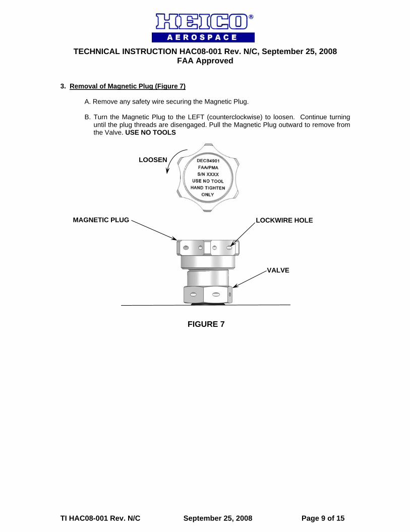
4. Removal of Valve (Figure 8)
A. Remove any safety wire securing the Valve. B. Remove the Valve from the NHA by turning the Valve counterclockwise, using the
wrenching flats only, until the Valve threads are free from the NHA port. C. Discard packing shown in Figure 8. D. To prevent contamination, plug or seal the NHA port as required.
CAUTION: Do not attempt to remove the Chip Collector as an assembly. To prevent damage, the Magnetic Plug must be removed from the Valve prior to installation (See Section 3).
NOTE: It is advisable to drain the lubricant from the NHA prior to removing the Valve.
DISCARD THIS PACKING
VALVE
FIGURE 8

TECHNICAL INSTRUCTION HAC08-001 Rev. N/C, September 25, 2008 FAA Approved
TI HAC08-001 Rev. N/C September 25, 2008 Page 11 of 15
5. Inspection of Chip Collector Assembly 5.1 Inspection of threads in the Magnetic Plug and Valve (Figure 9)
A. If the threads indicated with “A” are have become damaged, as evidenced by metallic shavings with missing or stripped threads, replace the Chip Collector Assembly. There are no repair procedures for the P/N DECB4901 Chip Collector Assembly.
B. If the threads indicated with “B” are damaged, as evidenced by metallic shavings with
missing or stripped threads,
1. Inspect the threads in the NHA for damage and repair, if required, as directed in the applicable manufacturer’s documentation.
2. Replace the Chip Collector Assembly. There are no repair procedures for the P/N
DECB4901 Chip Collector Assembly.
A
B
FIGURE 9

TECHNICAL INSTRUCTION HAC08-001 Rev. N/C, September 25, 2008 FAA Approved
TI HAC08-001 Rev. N/C September 25, 2008 Page 12 of 15
Ø.625 CARBON STEEL BALL
MAGNETIC PLUG
5.2 Magnetic Plug (Figure 10)
A. The magnetic plug must lift a 0.625 inch (15.875 mm) diameter carbon steel ball made to the material specifications that follow: AMS 6440, AMS 6444, AMS 6490, AMS 6491, AISI 52100, or AISI M50.
FIGURE 10
WARNING: Do not use a magnetic plug that will not lift a 0.625 inch (15.875 mm) diameter carbon steel ball.

TECHNICAL INSTRUCTION HAC08-001 Rev. N/C, September 25, 2008 FAA Approved
TI HAC08-001 Rev. N/C September 25, 2008 Page 13 of 15
6. Installation of Valve (Figure 11)
A. Remove the Magnetic Plug by holding the Chip Collector in one hand and turn the Magnetic Plug to the left (counterclockwise) until the plug threads are disengaged. Pull the Magnetic Plug outward to remove from the Valve.
B. Install the Valve into the threaded port on the applicable next higher assembly (ref.
Figures 2 thru 6). Using the wrenching flats only, torque the Valve Assembly 50 – 60 lb-in. (5.649 – 6.779 N.m).
C. Lockwire using AS3214-02 Safety Wire with 7 – 10 twists per inch and the twisted
portion of the wire within 1/8 inch from a lockwire hole. Make sure that the safety wire is installed in such a way that any tendency of the valve to loosen is counteracted by a tendency of the safety wire to tighten. Install the safety wire so that neither the safety wire nor adjacent components are subject to wear, chafing, or excessive load after installation. The span of safety wire between tension points must be less than 6 inches and no more than 24 inches of safety wire may be used.
NOTE: Prior to assembly, all packings are to be lubricated with engine oil which meets the specifications indicated in the latest revision of Type Certificate Data Sheet (TCDS) number E17NE.
CAUTION: Do not attempt to install the Chip Collector as an assembly. To prevent damage, the Magnetic Plug must be removed from the Valve prior to installation.
VALVE FIGURE 11
PACKING
PACKING
WRENCHING FLAT
LOCKWIRE HOLE

TECHNICAL INSTRUCTION HAC08-001 Rev. N/C, September 25, 2008 FAA Approved
TI HAC08-001 Rev. N/C September 25, 2008 Page 14 of 15
7. Installation of Magnetic Plug (Figure 12)
A. Insert the Magnetic Plug into the Valve.
B. Turn the Magnetic Plug to the right (clockwise) to tighten. Continue turning until
resistance is felt. Turn the magnetic plug assembly a maximum of ¼ turn past this point. USE NO TOOL - HAND TIGHTEN ONLY.
C. Lockwire using AS3214-02 Safety Wire with 7 – 10 twists per inch and the twisted
portion of the wire within 1/8 inch from a lockwire hole. Make sure that the safety wire is installed in such a way that any tendency of the magnetic plug to loosen is counteracted by a tendency of the safety wire to tighten. Install the safety wire so that neither the safety wire nor adjacent components are subject to wear, chafing, or excessive load after installation. The span of safety wire between tension points must be less than 6 inches and no more than 24 inches of safety wire may be used.
TIGHTEN
MAGNETIC PLUG
VALVE
LOCKWIRE HOLE
FIGURE 12
NOTE: Prior to assembly, all packings are to be lubricated with engine oil which meets the specifications indicated in the latest revision of Type Certificate Data Sheet (TCDS) number E17NE.
MAGNETIC PLUG
PACKING
TECHNICAL INSTRUCTION HAC08-001 Rev. N/C, September 25, 2008 FAA Approved
TI HAC08-001 Rev. N/C September 25, 2008 Page 15 of 15
8. Material Information This document will be maintained and the latest approved revision posted on the HEICO web site at http://ipc.heico.com . 9. Revision and Approval History Initial Release – September 25, 2008