Technical Information / Operating Instructions Radiation ...62.pdf · Technical Information /...
44
TI435F/00/en/09.109 71122562 Technical Information / Operating Instructions Radiation Source Container FQG61/FQG62 Radiometric Measurement Container with source holder for manual or pneumatic switch-ON/switch-OFF Application The FQG61 and FQG621 source containers are designed to hold the radioactive source during radiometric level limit measurement, level measurement and density measurement. The radiation is emitted almost unattenuated in one direction only, and is damped in all other directions. FQG61 and FQG62 differ from each other in terms of size and screening effect. Your benefits • Lightweight device provides best possible screening thanks to almost spherical design • Safe and easy source replacement • Highest safety classification for the source supplied (DIN 25426/ISO 2919, typical classification C66646) • Compact device that is easy to mount • Various angles of emission for optimum adaptation to the application • Manual or pneumatic switch-ON/switch-OFF • Padlock, cylinder lock or locking bolt for fixing the switching position • Switch status easily identified
Transcript of Technical Information / Operating Instructions Radiation ...62.pdf · Technical Information /...
TI435F/00/en/09.109
71122562
Technical Information / Operating Instructions
Radiation Source ContainerFQG61/FQG62Radiometric Measurement
Container with source holder for manual or pneumatic
switch-ON/switch-OFF
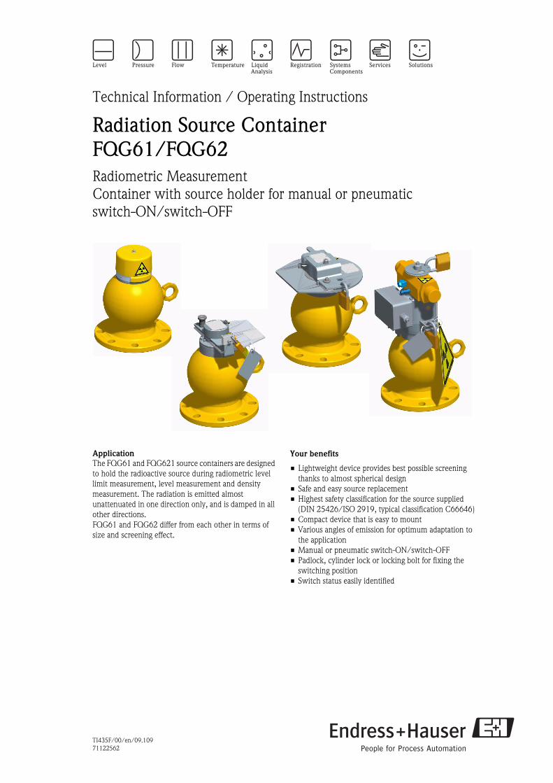
Application
The FQG61 and FQG621 source containers are designed
to hold the radioactive source during radiometric level
limit measurement, level measurement and density
measurement. The radiation is emitted almost
unattenuated in one direction only, and is damped in all
other directions.
FQG61 and FQG62 differ from each other in terms of
size and screening effect.
Your benefits
• Lightweight device provides best possible screening
thanks to almost spherical design
• Safe and easy source replacement
• Highest safety classification for the source supplied
(DIN 25426/ISO 2919, typical classification C66646)
• Compact device that is easy to mount
• Various angles of emission for optimum adaptation to
the application
• Manual or pneumatic switch-ON/switch-OFF
• Padlock, cylinder lock or locking bolt for fixing the
switching position
• Switch status easily identified
Radiation Source Container FQG61/FQG62
Table of contents
Safety Instructions . . . . . . . . . . . . . . . . . . . . . . . . . . . . 3 Reading the switch status . . . . . . . . . . . . . . . . . . . . . . . . . . . . . . 25
Designated use . . . . . . . . . . . . . . . . . . . . . . . . . . . . . . . . . . . . . . . 3
Basic Instructions for use and storage . . . . . . . . . . . . . . . . . . . . . . 3
Hazardous area . . . . . . . . . . . . . . . . . . . . . . . . . . . . . . . . . . . . . . . 3
General instructions on radiation protection . . . . . . . . . . . . . . . . . 4
Legal requirements for radiation protection . . . . . . . . . . . . . . . . . . 4
Supplementary Instructions . . . . . . . . . . . . . . . . . . . . . . . . . . . . . 4
Notes on safety conventions and icons . . . . . . . . . . . . . . . . . . . . . 5
Function and system design. . . . . . . . . . . . . . . . . . . . . 6
Function . . . . . . . . . . . . . . . . . . . . . . . . . . . . . . . . . . . . . . . . . . . 6
Attenuation factor and half-value layers . . . . . . . . . . . . . . . . . . . . 6
Maximum activity of the radiation source . . . . . . . . . . . . . . . . . . . 6
Dose rate diagrams . . . . . . . . . . . . . . . . . . . . . . . . . . . . . . . . . . . . 7
Mechanical construction . . . . . . . . . . . . . . . . . . . . . . . 8
Version . . . . . . . . . . . . . . . . . . . . . . . . . . . . . . . . . . . . . . . . . . . . 8
Design, Dimensions . . . . . . . . . . . . . . . . . . . . . . . . . . . . . . . . . . . 8
Radiation emission channel . . . . . . . . . . . . . . . . . . . . . . . . . . . . . 11
Weight . . . . . . . . . . . . . . . . . . . . . . . . . . . . . . . . . . . . . . . . . . . . 12
Materials . . . . . . . . . . . . . . . . . . . . . . . . . . . . . . . . . . . . . . . . . . 12
Safety equipment . . . . . . . . . . . . . . . . . . . . . . . . . . . . . . . . . . . . 12
Pneumatic actuator . . . . . . . . . . . . . . . . . . . . . . . . . . . . . . . . . . 12
Ambient conditions . . . . . . . . . . . . . . . . . . . . . . . . . . 12
Ambient temperature . . . . . . . . . . . . . . . . . . . . . . . . . . . . . . . . . 12
Ambient pressure . . . . . . . . . . . . . . . . . . . . . . . . . . . . . . . . . . . . 12
Vibration resistance . . . . . . . . . . . . . . . . . . . . . . . . . . . . . . . . . . 12
Fire . . . . . . . . . . . . . . . . . . . . . . . . . . . . . . . . . . . . . . . . . . . . . . 12
Identification . . . . . . . . . . . . . . . . . . . . . . . . . . . . . . . 13
Nameplates . . . . . . . . . . . . . . . . . . . . . . . . . . . . . . . . . . . . . . . . 13
Installation. . . . . . . . . . . . . . . . . . . . . . . . . . . . . . . . . 16
Incoming acceptance, transport . . . . . . . . . . . . . . . . . . . . . . . . . 16
Mounting hints . . . . . . . . . . . . . . . . . . . . . . . . . . . . . . . . . . . . . 16
Mounting position for level measurement . . . . . . . . . . . . . . . . . . 17
Mounting position for level limit detection . . . . . . . . . . . . . . . . . 18
Mounting position for density measurement . . . . . . . . . . . . . . . . 18
Orientation of the fireproof version . . . . . . . . . . . . . . . . . . . . . . . 19
Mounting device (supplied by customer) . . . . . . . . . . . . . . . . . . . 20
Toothed lock washers . . . . . . . . . . . . . . . . . . . . . . . . . . . . . . . . . 20
Torque for the mounting screws . . . . . . . . . . . . . . . . . . . . . . . . . 20
Post-installation check . . . . . . . . . . . . . . . . . . . . . . . . . . . . . . . . 21
Connection of the pneumatic actuator. . . . . . . . . . . . 22
Compressed-air connection . . . . . . . . . . . . . . . . . . . . . . . . . . . . 22
Connection of the proximity switches . . . . . . . . . . . . . . . . . . . . . 23
Commissioning . . . . . . . . . . . . . . . . . . . . . . . . . . . . . . . . . . . . . 24
Reading the switch status . . . . . . . . . . . . . . . . . . . . . . . . . . . . . . 24
Technical data of the pneumatic actuator . . . . . . . . . . . . . . . . . . 24
Operation: FQG6x - #A ... . . . . . . . . . . . . . . . . . . . . . 25
Safety instructions for switching on the radiation . . . . . . . . . . . . . 25
Switching radiation ON . . . . . . . . . . . . . . . . . . . . . . . . . . . . . . . 25
Switching radiation OFF . . . . . . . . . . . . . . . . . . . . . . . . . . . . . . . 25
2
Operation: FQG6x - #B ... . . . . . . . . . . . . . . . . . . . . . 26
Safety instructions for switching on the radiation . . . . . . . . . . . . 26
Switching radiation ON . . . . . . . . . . . . . . . . . . . . . . . . . . . . . . . 26
Switching radiation OFF . . . . . . . . . . . . . . . . . . . . . . . . . . . . . . . 26
Operation: FQG6x - #C ... . . . . . . . . . . . . . . . . . . . . . 27
Safety instructions for switching on the radiation . . . . . . . . . . . . 27
Switching radiation ON . . . . . . . . . . . . . . . . . . . . . . . . . . . . . . . 27
Switching radiation OFF . . . . . . . . . . . . . . . . . . . . . . . . . . . . . . . 27
Operation: FQG6x - #D ... . . . . . . . . . . . . . . . . . . . . . 28
Safety instructions for switching on the radiation . . . . . . . . . . . . 28
Switching radiation ON . . . . . . . . . . . . . . . . . . . . . . . . . . . . . . . 28
Switching radiation OFF . . . . . . . . . . . . . . . . . . . . . . . . . . . . . . . 28
Maintenance and Inspection . . . . . . . . . . . . . . . . . . . 29
Cleaning . . . . . . . . . . . . . . . . . . . . . . . . . . . . . . . . . . . . . . . . . . 29
Maintenance and Inspection . . . . . . . . . . . . . . . . . . . . . . . . . . . 29
Routine test of the shutter mechanism . . . . . . . . . . . . . . . . . . . . 30
Routine leak test procedure . . . . . . . . . . . . . . . . . . . . . . . . . . . . 31
Emergency procedure . . . . . . . . . . . . . . . . . . . . . . . . 32
Objective and overview . . . . . . . . . . . . . . . . . . . . . . . . . . . . . . . 32
Emergency procedure . . . . . . . . . . . . . . . . . . . . . . . . . . . . . . . . 32
Notification to authority . . . . . . . . . . . . . . . . . . . . . . . . . . . . . . . 32
Procedures after termination of the application. . . . . 33
Internal measures . . . . . . . . . . . . . . . . . . . . . . . . . . . . . . . . . . . 33
Return . . . . . . . . . . . . . . . . . . . . . . . . . . . . . . . . . . . . . . . . . . . . 33
Ordering information. . . . . . . . . . . . . . . . . . . . . . . . . 34
Product structure FQG61 . . . . . . . . . . . . . . . . . . . . . . . . . . . . . . 34
Product structure FQG62 . . . . . . . . . . . . . . . . . . . . . . . . . . . . . . 36
Scope of delivery . . . . . . . . . . . . . . . . . . . . . . . . . . . . . . . . . . . . 37
Delivery . . . . . . . . . . . . . . . . . . . . . . . . . . . . . . . . . . . . . . . . . . . 37
Accessories . . . . . . . . . . . . . . . . . . . . . . . . . . . . . . . . 38
Clamping device FHG61 . . . . . . . . . . . . . . . . . . . . . . . . . . . . . . 38
Measuring path FHG62 . . . . . . . . . . . . . . . . . . . . . . . . . . . . . . . 39
Associated documentation . . . . . . . . . . . . . . . . . . . . . 40
Gamma Radiation Source . . . . . . . . . . . . . . . . . . . . . . . . . . . . . . 40
Clamping Device FHG61 . . . . . . . . . . . . . . . . . . . . . . . . . . . . . . 40
Measuring Path FHG62 . . . . . . . . . . . . . . . . . . . . . . . . . . . . . . . 40
Gamma Modulator FHG65
Synchronizer FHG66 . . . . . . . . . . . . . . . . . . . . . . . . . . . . . . . . . 40
Radiation Source Container QG2000 . . . . . . . . . . . . . . . . . . . . . 40
Gammapilot M FMG60 . . . . . . . . . . . . . . . . . . . . . . . . . . . . . . . 40
Gammapilot FTG470Z . . . . . . . . . . . . . . . . . . . . . . . . . . . . . . . . 40
Detectors DG17/DG27 . . . . . . . . . . . . . . . . . . . . . . . . . . . . . . . 40
Supplementary Instruction Manuals . . . . . . . . . . . . . . . . . . . . . . 41
Manufacturer Declaration Radiation Source Container . . . . . . . . 42
Manufacturer Declaration Packaging . . . . . . . . . . . . . . . . . . . . . 43
Endress+Hauser
Radiation Source Container FQG61/FQG62
Safety Instructions
Designated use The FQG61 and FQG62 source containers described in this document contain the radioactive source, which
is used for radiometric measurement of level, interface and density. It screens the radiation towards the
surrounding and allows it to be emitted almost unattenuated only in the direction of the measurement.
In order to guarantee the screening effect and to exclude damage of the radiation source, all instructions given
in this Technical Information for mounting and operation as well as all regulations for radioactive protection
are to be followed exactly.
Endress+Hauser accepts no responsibility for any damage caused by incorrect use.
Basic Instructions for use and
storage
• Observe the applying rules and national regulations.
• Observe the radiation protection regulations in use, storage and for work on the radiometric measuring
system.
• Observe warning signs and safety areas.
• Install and operate the device according to this manual and the relevant conditions as specified by the
regulatory authority.
• The device shall not be operated or stored outside the specified parameters.
• Protect the device against extreme influences (i.e. chemical products, weather, mechanical impacts,
vibrations) when operated or stored.
• Always secure the OFF position of the source insert using the padlock.
• Before switching ON the radiation beam it is necessary to ensure that no personnel are within the area of
the radiation (or, indeed, inside the vessel). The radiation beam may only be switched ON by specially
trained personnel.
• Do not operate or store damaged or corroded devices. Contact the responsible radiation safety officer for
appropriate instructions and measures when damage or corrosion occurs.
• Conduct the required leak testing procedure according to the applying regulations and instructions.
# Warning!
If the instrument is exposed to strong vibrations or mechanical impacts, the safety pin can become abraded.
This may lead to a loss of the source insert. Stability and tightness of the source insert must be checked in
periodical intervals.
" Caution!
In case of doubt about proper condition of the device check the area around the device for leakage radiation
and/or contact immediately the responsible radiation safety officer.
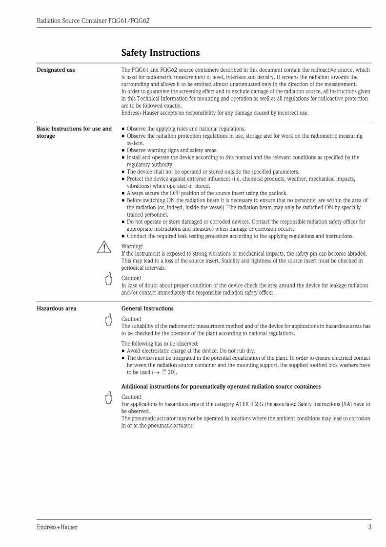
Hazardous area General Instructions
" Caution!
The suitability of the radiometric measurment method and of the device for applications in hazardous areas has
to be checked by the operator of the plant according to national regulations.
The following has to be observed:
• Avoid electrostatic charge at the device. Do not rub dry.
• The device must be integrated in the potential equalization of the plant. In order to ensure electrical contact
between the radiation source container and the mounting support, the supplied toothed lock washers have
to be used (→ ä 20).
Additional instructions for pneumatically operated radiation source containers
" Caution!
For applications in hazardous area of the category ATEX II 2 G the associated Safety Instructions (XA) have to
be observed.
The pneumatic actuator may not be operated in locations where the ambient conditions may lead to corrosion
in or at the pneumatic actuator.
Endress+Hauser 3

Radiation Source Container FQG61/FQG62
General instructions on
radiation protection
When working with radioactive sources, any unnecessary exposure to radiation must be avoided. Unavoidable
exposure to radiation must be kept to as low a level as possible. Three important measures help you to achieve
this:
L00-QGxxxxxx-16-00-00-en-001
Screening
Ensure the screening between the radiation source and you and all other persons is as good as possible. Source
containers (e.g. FQG61/FQG62) and all high-density materials (lead, iron, concrete etc.), can be used for
effective screening purposes.
Time
Time spent in the exposed area should be kept to a minimum.
Distance
Keep at as large a distance as possible from the radiation source. The local dose rate of the radiation decreases
with the square of the distance from the radiation source.
Legal requirements for
radiation protection
Handling radioactive sources is legally controlled. The radiation protection regulations of the country in which
the plant is to be operated are to be strictly observed. For example, the valid radiation protection requirements
are applicable in Germany. The following important points derived from this for radioactive measurement are:
Handling permit
A handling permit is required for operating a plant which uses gamma radiation. Application for the permit
must be made to the Land government or the authority responsible (Land Offices for Environmental Protection,
Trade Inspection Offices, etc.). The Endress+Hauser Sales Organization will be pleased to help you to obtain
the permit.
Radiation Safety Officer
The operator of the plant must nominate someone responsible for radiation protection who has the necessary
specialist knowledge and who is responsible for observing all radiation protection regulations and procedures
for radiation protection. Endress+Hauser offers training courses in which the necessary specialist knowledge
can be acquired.
Control area
Only persons exposed to radiation during the course of their job may sojourn in control areas (i.e. areas where
the local dose rate exceeds a specific value) provided they are subjected to official personnel dose monitoring
procedures. For the Federal Republic of Germany the limit values for the control area are specified in the
current radiation protection requirements.
The Endress+Hauser sales office will be pleased to provide further information of radiation protection and
regulations in other countries.
Supplementary Instructions Observe the associated Instruction Manuals SD292F (for Canada) and SD293F (for the USA).
! Note!
This document represents in combination with the nameplates the documentation for "hochradioaktive
Strahlenquellen" according to StSchV §69(2) in Germany.
4 Endress+Hauser

Radiation Source Container FQG61/FQG62
Notes on safety conventions
and icons
In order to highlight safety-relevant or alternative operating procedures in the manual, the following
conventions have been used, each indicated by a corresponding icon in the margin.
Symbol Meaning
#Warning!
A warning highlights actions or procedures which, if not performed correctly, will lead to
personal injury, a safety hazard or destruction of the instrument.
"Caution!
Caution highlights actions or procedures which, if not performed correctly, may lead to
personal injury or incorrect functioning of the instrument.
!Note!
A note highlights actions or procedures which, if not performed correctly, may indirectly
affect operation or may lead to an instrument response which is not planned.
0Device certified for use in explosion hazardous area
If the device has this symbol embossed on its nameplate, it can be installed in an explosion
hazardous area or a non-explosion hazardous area, according to the approval.
-Explosion hazardous area
Symbol used in drawings to indicate explosion hazardous areas.
– Devices used in hazardous areas must possess an appropriate type of protection.
. Safe area (non-explosion hazardous area)
Symbol used in drawings to indicate, if necessary, non-explosion hazardous areas.
– Devices used in hazardous areas must possess an appropriate type of protection. Lines
used in hazardous areas must meet the necessary safety-related characteristic quantities.
% Direct voltage
A terminal to which or from which a direct current or voltage may be applied or supplied.
&Alternating voltage
A terminal to which or from which an alternating (sine-wave) current or voltage may be
applied or supplied.
)Grounded terminal
A grounded terminal, which as far as the operator is concerned, is already grounded by
means of an earth grounding system.
*Protective grounding (earth) terminal
A terminal which must be connected to earth ground prior to making any other connection
to the equipment.
+Equipotential connection (earth bonding)
A connection made to the plant grounding system which may be of type e.g. neutral star or
equipotential line according to national or company practice.
Radioactivity
Marks containers for radioactive materials and areas in which radioactive material is
present.
Endress+Hauser 5
Radiation Source Container FQG61/FQG62
Function and system design
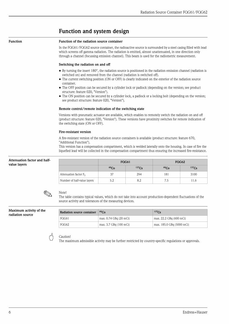
Function Function of the radiation source container
In the FQG61/FQG62 source container, the radioactive source is surrounded by a steel casing filled with lead
which screens off gamma radiation. The radiation is emitted, almost unattenuated, in one direction only
through a channel (focussing emission channel). This beam is used for the radiometric measurement.
Switching the radiation on and off
• By turning the insert 180°, the radiation source is positioned in the radiation emission channel (radiation is
switched on) and removed from the channel (radiation is switched off).
• The current switching position (ON or OFF) is clearly indicated on the exterior of the radiation source
container.
• The OFF position can be secured by a cylinder lock or padlock (depending on the version; see product
structure: feature 020, "Version").
• The ON position can be secured by a cylinder lock, a padlock or a locking bolt (depending on the version;
see product structure: feature 020, "Version").
Remote control/remote indication of the switching state
Versions with pneumatic actuator are available, which enables to remotely switch the radiation on and off
(product structure: feature 020, "Version"). These versions have proximity switches for remote indication of
the switching state (ON or OFF).
Fire-resistant version
A fire-resistant version of the radiation source containers is available (product structure: feature 670,
"Additional Function").
This version has a compensation compartment, which is welded laterally onto the housing. In case of fire the
liquefied lead will be collected in the compensation compartment thus ensuring the increased fire-resistance.
Attenuation factor and half-
value layers
! Note!
The table contains typical values, which do not take into account production-dependent fluctuations of the
source activity and tolerances of the measuring devices.
Maximum activity of the
radiation source
" Caution!
The maximum admissible activity may be further restricted by country-specific regulations or approvals.
FQG61 FQG62
60Co 137Cs 60Co 137Cs
Attenuation factor FS 37 294 181 3100
Number of half-value layers 5.2 8.2 7.5 11.6
Radiation source container 60Co 137Cs
FQG61 max. 0.74 GBq (20 mCi) max. 22.2 GBq (600 mCi)
FQG62 max. 3.7 GBq (100 mCi) max. 185.0 GBq (5000 mCi)
6 Endress+Hauser

Radiation Source Container FQG61/FQG62
Dose rate diagrams A dose rate diagram specifies the local dose rate in a specified distance from the surface of the radiation source
container. Below you find examples of dose rate diagrams for FQG61 and FQG62. They are valid for a distance
of 1 m and for selected activites of a 60Co or 137Cs radiation source and refer to the radiation being switched
OFF.
Dose rate diagrams for other distances and activities are available on request.
Dose rate diagrams for 60Co
L00-FQG6xxxx-05-00-00-xx-001
Dose rate diagrams for 137Cs
L00-FQG6xxxx-05-00-00-xx-002
45°
90°
135°
180°
225°
270°
315°
�Sv/h
10
8
6
4
2
FQG61 - Co60 - 20 mCi (0.74 GBq) - 1m
�Sv/h
10
8
6
4
2
45°
90°
135°
180°
225°
270°
315°
FQG62 - Co60 - 100 mCi (3.7 GBq) - 1m
45°
0°
135°
180°
225°
270°
315°
�Sv/h
2,52,01,51,00,5
45°
0°
135°
180°
225°
270°
315°
�Sv/h
1,00,80,60,40,2
6 Sv/h�
FQG61 - Cs137 - 100mCi (3.7 GBq) - 1 m FQG62 - Cs137 - 1000mCi (37 GBq) - 1 m
Endress+Hauser 7

Radiation Source Container FQG61/FQG62
Mechanical construction
Version
Design, Dimensions Standard design
L00-FQG6xxxx-06-00-00-xx-001
Dimensions in mm
*: clearance for removal of the cover
**: clearance required for exchange of the radiation source
Feature 020 of the
product structure
Properties Comparable to
QG020/QG100 in the
following version
A • Source holder for manual sitch-ON/switch-OFF
• Cylinder lock to secure switching state (ON or OFF)
• Covering cap
Standard
B • Rotary bracket for manual switch-ON/switch-OFF
• Locking bolt to secure the ON switching state
• Padlock to secure the OFF switching state
US, Australia
C • Rotary bracket for manual switch-ON/switch-OFF
• Padlock to secure the switching state (ON or OFF)
Euro, Sweden,
Norway
D • Higher protection against dust and humidity
• Rotary bracket for manual switch-ON/switch-OFF
• Padlock to secure the switching state (ON or OFF)
Chemical
K
L
• Pneumatic switch-ON/switch-OFF
• Padlock to secure the OFF switching state
Standard - with
pneumatic actuator
M
N
• Higher protection against dust and humidity
• Pneumatic switch-ON/switch-OFF
• Padlock to secure the OFF switching state
Chemical - with
pneumatic actuator
FQ
G6
1-#
A..
.:
27
9F
QG
62
-#A
...
:3
60
20
75
*
ø220FQG61-#A ... : 251FQG62-#A ... : 272
FQ
G6
1-#
A..
.:
47
9**
FQ
G6
2-#
A..
.:
56
0**
8 Endress+Hauser

Radiation Source Container FQG61/FQG62
FQG61 - #B... / FQG62 - #B...
L00-FQG6xxxx-06-00-00-xx-002
Dimensions in mm
*: clearance required for exchange of the radiation source
FQG61 - #C... / FQG62 - #C...
L00-FQG6xxxx-06-00-00-xx-003
Dimensions in mm
*: clearance required for exchange of the radiation source
FQ
G6
1-#
B...:2
87
FQ
G6
2-#
B...:3
68
FQ
G6
1-#
B...:4
50
*F
QG
62
-#B
...:5
80
*
20
ø220FQG61-#B ... : 251FQG62-#B ... : 272
FQ
G6
1-#
C..
.:
28
7F
QG
62
-#C
...
:3
68
FQ
G6
1-#
C..
.:
45
0*
FQ
G6
2-#
C..
.:
57
0*
20
ø220FQG61-#C ... : 251FQG62-#C ... : 272
Endress+Hauser 9
Radiation Source Container FQG61/FQG62
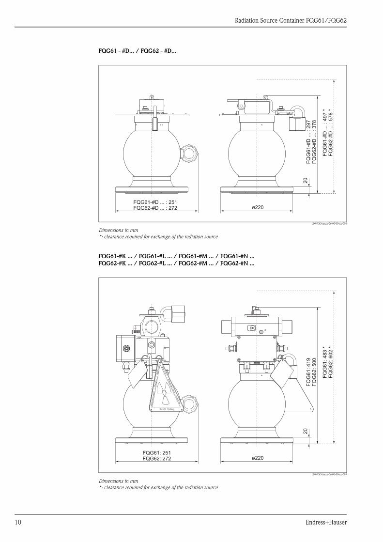
FQG61 - #D... / FQG62 - #D...
L00-FQG6xxxx-06-00-00-xx-004
Dimensions in mm
*: clearance required for exchange of the radiation source
FQG61-#K ... / FQG61-#L ... / FQG61-#M ... / FQG61-#N ...
FQG62-#K ... / FQG62-#L ... / FQG62-#M ... / FQG62-#N ...
L00-FQG6xxxx-06-00-00-xx-005
Dimensions in mm
*: clearance required for exchange of the radiation source
FQ
G6
1-#
D...:2
97
FQ
G6
2-#
D...:3
78
FQ
G6
1-#
D...:4
97
*F
QG
62
-#D
...:5
78
*
20
ø220FQG61-#D ... : 251FQG62-#D ... : 272
FQ
G6
1:
41
9F
QG
62
:5
00
FQ
G6
1:
48
3*
FQ
G6
2:
60
2*
20
ø220FQG61: 251FQG62: 272
10 Endress+Hauser
Radiation Source Container FQG61/FQG62
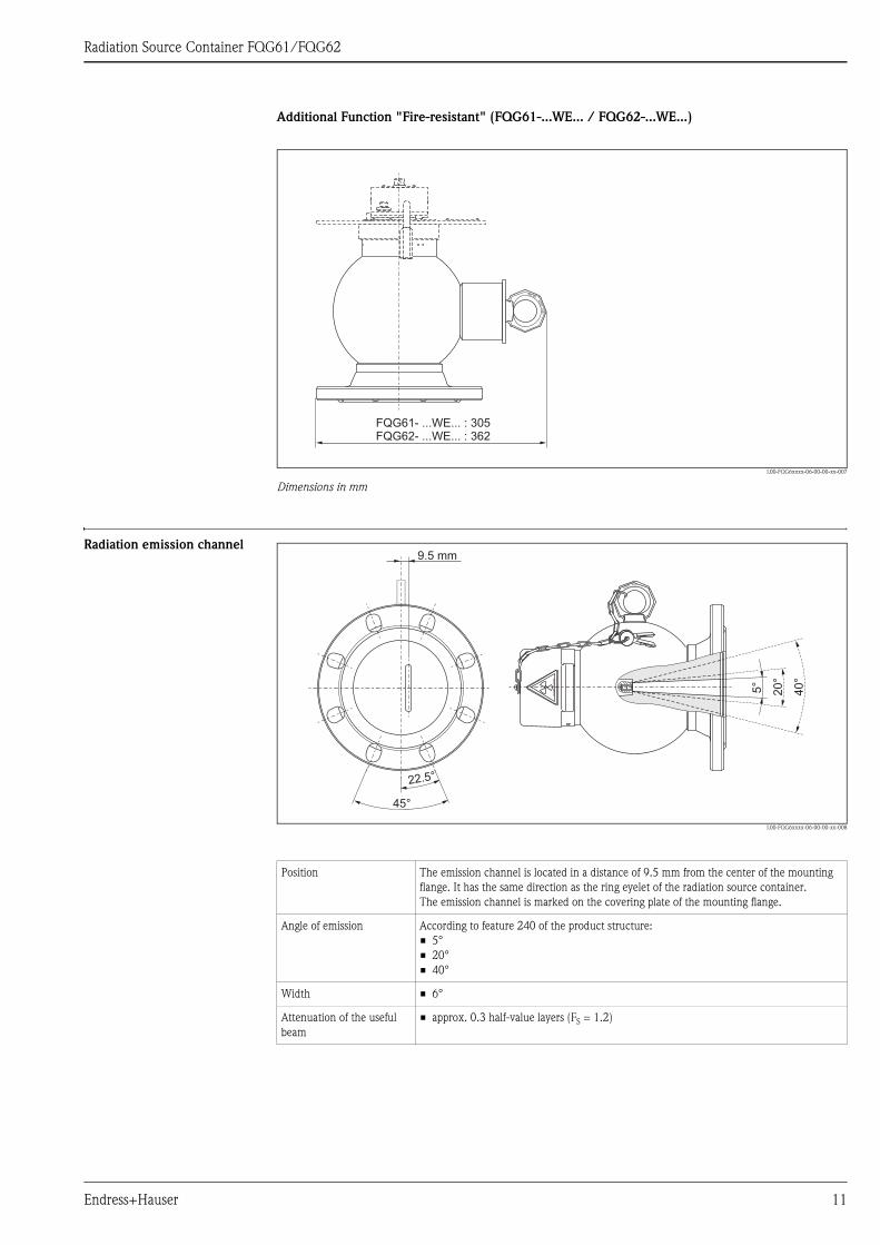
Additional Function "Fire-resistant" (FQG61-...WE... / FQG62-...WE...)
L00-FQG6xxxx-06-00-00-xx-007
Dimensions in mm
Radiation emission channel
L00-FQG6xxxx-06-00-00-xx-008
FQG61- ...WE... : 305FQG62- ...WE... : 362
Position The emission channel is located in a distance of 9.5 mm from the center of the mounting
flange. It has the same direction as the ring eyelet of the radiation source container.
The emission channel is marked on the covering plate of the mounting flange.
Angle of emission According to feature 240 of the product structure:
• 5°
• 20°
• 40°
Width • 6°
Attenuation of the useful
beam
• approx. 0.3 half-value layers (FS = 1.2)
9.5 mm
45°
22.5°
5°
20
°
40
°
Endress+Hauser 11
Radiation Source Container FQG61/FQG62
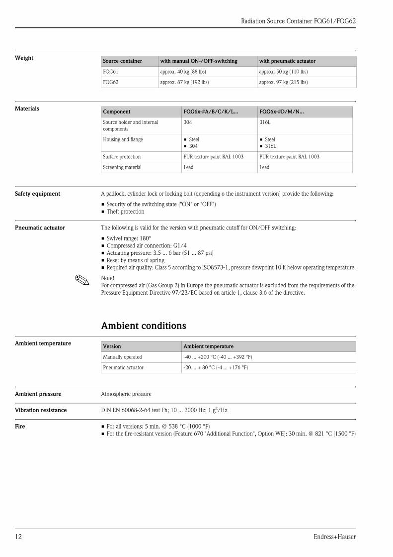
Weight
Materials
Safety equipment A padlock, cylinder lock or locking bolt (depending o the instrument version) provide the following:
• Security of the switching state ("ON" or "OFF")
• Theft protection
Pneumatic actuator The following is valid for the version with pneumatic cutoff for ON/OFF switching:
• Swivel range: 180°
• Compressed air connection: G1/4
• Actuating pressure: 3.5 ... 6 bar (51 ... 87 psi)
• Reset by means of spring
• Required air quality: Class 5 according to ISO8573-1, pressure dewpoint 10 K below operating temperature.
! Note!
For compressed air (Gas Group 2) in Europe the pneumatic actuator is excluded from the requirements of the
Pressure Equipment Directive 97/23/EC based on article 1, clause 3.6 of the directive.
Ambient conditions
Ambient temperature
Ambient pressure Atmospheric pressure
Vibration resistance DIN EN 60068-2-64 test Fh; 10 ... 2000 Hz; 1 g2/Hz
Fire • For all versions: 5 min. @ 538 °C (1000 °F)
• For the fire-resistant version (Feature 670 "Additional Function", Option WE): 30 min. @ 821 °C (1500 °F)
Source container with manual ON-/OFF-switching with pneumatic actuator
FQG61 approx. 40 kg (88 lbs) approx. 50 kg (110 lbs)
FQG62 approx. 87 kg (192 lbs) approx. 97 kg (215 lbs)
Component FQG6x-#A/B/C/K/L... FQG6x-#D/M/N...
Source holder and internal
components
304 316L
Housing and flange • Steel
• 304
• Steel
• 316L
Surface protection PUR texture paint RAL 1003 PUR texture paint RAL 1003
Screening material Lead Lead
Version Ambient temperature
Manually operated -40 ... +200 °C (-40 ... +392 °F)
Pneumatic actuator -20 ... + 80 °C (-4 ... +176 °F)
12 Endress+Hauser

Radiation Source Container FQG61/FQG62
Identification
Nameplates FQG6x-#A...
FQG6xxxx-18-00-00-yy-001
A: Nameplate "radiation source container"
B: Nameplate "source capsule"
C: Additional label "source capsule"
1: Ident number of radiation source container
2: Serial number of radiation source container
3: Order code of radiation source container according to product structure (→ ä 34)
4: Radiation emission angle
5: Local dose rate at a defined distance from the surface
6: Endress+Hauser internal order code of the radiation source
7: Endress+Hauser internal serial number of the radiation source
8: Wording "Hochradioaktive Strahlenquelle" (highly radioactive source), depending on activity1)
9: "Cs137" or "Co60"
10: Serial number of the source capsule (intended for source tracking if required)
11: Activity in MBq or GBq
12: Date (month/year)
13: Data Matrix Code (optional)
! Note!
The local dose rate at a defined distance specified on the nameplate is based on a worst-case estimation and
takes into account production-dependent fluctuations of the source activity and tolerances of the measuring
devices. Therefore it may be slightly different from the local dose rate which can be calculated from the
specified attenuation factors (page 6).
A
B
C
A
B
C
A
B
AUS OFF EIN ON14
52
3
FQG
250002809--
Made in Germany, D-79689 MaulburgMade in Germany, D-79689 Maulburg
Order Code:
Ident-No.:
Ser.No.:
Order Code:
250002619--
Made in Germany,D-79689 Maulburg
Caution radioactive material
Radionuclide:
Gamma source
Dat.:
Activity:
Source/Serial No:
8
13
69101112
67
8
91011
12 250002810--Dat.:
Activity:
Gamma sourceGamma source
Order Code: Radionuclide
Ser. No:Ser. No: Source No:Source No:
Caution Radioactive MaterialCaution Radioactive Material
1) Required by German regulations
Endress+Hauser 13
Radiation Source Container FQG61/FQG62
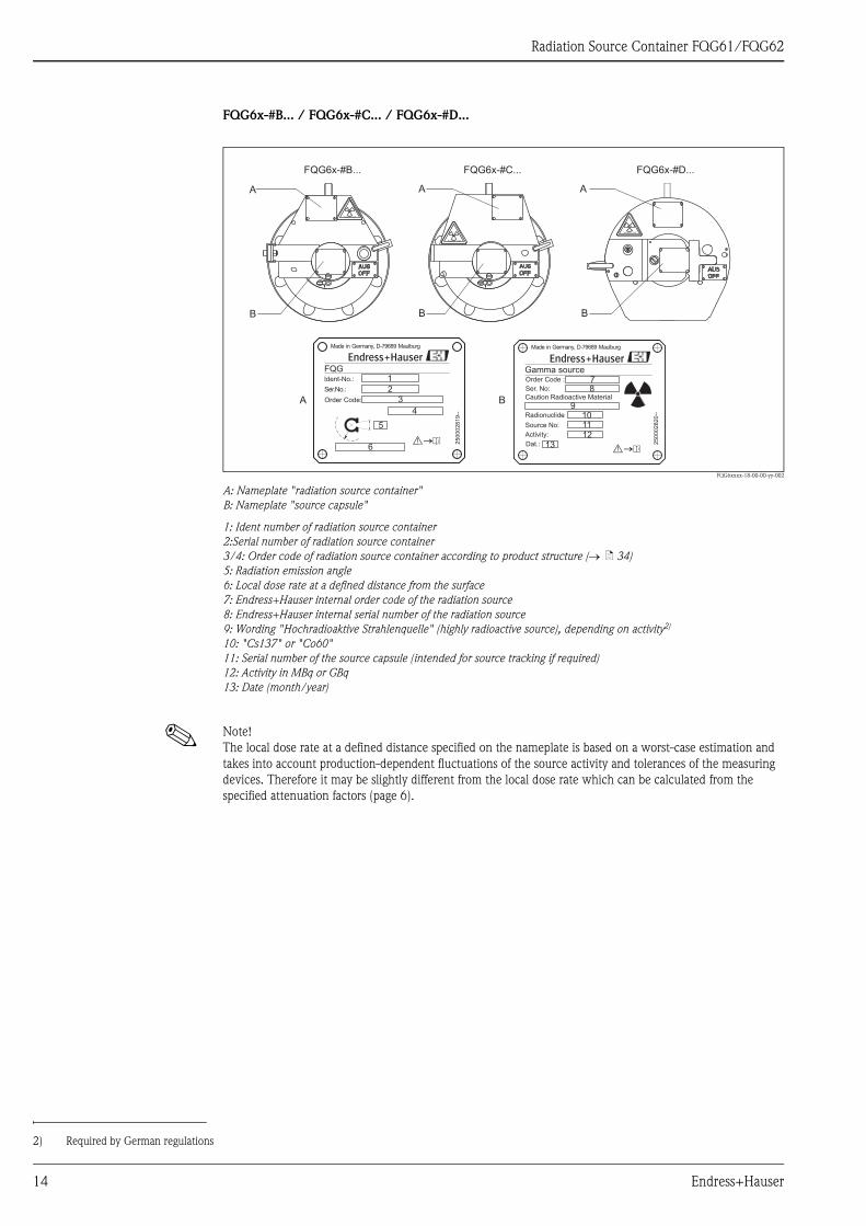
FQG6x-#B... / FQG6x-#C... / FQG6x-#D...
FQG6xxxx-18-00-00-yy-002
A: Nameplate "radiation source container"
B: Nameplate "source capsule"
1: Ident number of radiation source container
2:Serial number of radiation source container
3/4: Order code of radiation source container according to product structure (→ ä 34)
5: Radiation emission angle
6: Local dose rate at a defined distance from the surface
7: Endress+Hauser internal order code of the radiation source
8: Endress+Hauser internal serial number of the radiation source
9: Wording "Hochradioaktive Strahlenquelle" (highly radioactive source), depending on activity2)
10: "Cs137" or "Co60"
11: Serial number of the source capsule (intended for source tracking if required)
12: Activity in MBq or GBq
13: Date (month/year)
! Note!
The local dose rate at a defined distance specified on the nameplate is based on a worst-case estimation and
takes into account production-dependent fluctuations of the source activity and tolerances of the measuring
devices. Therefore it may be slightly different from the local dose rate which can be calculated from the
specified attenuation factors (page 6).
FQG6x-#B... FQG6x-#C... FQG6x-#D...
A
B
A
B
A
B
A B
1
23
4
6
5
FQG
Made in Germany, D-79689 Maulburg
250002819--
Order Code:
Ident-No.:
Ser.No.:
7
9
8
101112
13 250002820--
Source No:
Radionuclide
Ser. No:
Gamma source
Made in Germany, D-79689 Maulburg
Dat.:
Order Code :
Activity:
Caution Radioactive Material
2) Required by German regulations
14 Endress+Hauser
Radiation Source Container FQG61/FQG62
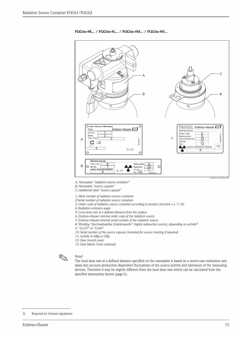
FQG6x-#K... / FQG6x-#L... / FQG6x-#M... / FQG6x-#N...
FQG6xxxx-18-00-00-yy-003
A: Nameplate "radiation source container"
B: Nameplate "source capsule"
C: Additional label "source capsule"
1: Ident number of radiation source container
2:Serial number of radiation source container
3: Order code of radiation source container according to product structure (→ ä 34)
4: Radiation emission angle
5: Local dose rate at a defined distance from the surface
6: Endress+Hauser internal order code of the radiation source
7: Endress+Hauser internal serial number of the radiation source
8: Wording "Hochradioaktive Strahlenquelle" (highly radioactive source), depending on activity3)
9: "Cs137" or "Co60"
10: Serial number of the source capsule (intended for source tracking if required)
11: Activity in MBq or GBq
12: Date (month/year)
13: Data Matrix Code (optional)
! Note!
The local dose rate at a defined distance specified on the nameplate is based on a worst-case estimation and
takes into account production-dependent fluctuations of the source activity and tolerances of the measuring
devices. Therefore it may be slightly different from the local dose rate which can be calculated from the
specified attenuation factors (page 6).
A
B B
C
A
B
C
12
5
4
3
Made in Germany, D-79689 MaulburgMade in Germany, D-79689 Maulburg
250002821-
-
FQG
Ident-No.:
Ser.No.:
Order Code:
67
8
91011
12 250002810--Dat.:
Activity:
Gamma sourceGamma source
Order Code: Radionuclide
Ser. No:Ser. No: Source No:Source No:
Caution Radioactive MaterialCaution Radioactive Material
Order Code:
250002619--
Made in Germany,D-79689 Maulburg
Caution radioactive material
Radionuclide:
Gamma source
Dat.:
Activity:
Source/Serial No:
8
13
69101112
3) Required by German regulations
Endress+Hauser 15
Radiation Source Container FQG61/FQG62
Installation
Incoming acceptance,
transport
The radiation source container serves as a type-A packaging (IATA rules) for the radiation source. For transport,
it is protected by a foam packaging.
Dimensions of the packaging:
• without pneumatic actuator: 380 mm x 380 mm x 450 mm (15" x 15" x 18")
• with pneumatic actuator: 380 mm x 380 mm x 600 mm (15" x 15" x 24")
! Note!
The foam packaging can be disposed like ordinary consumer waste.
Mounting hints The radiation source container can be mounted in one of the following ways:
• by a nozzle directly on the vessel or pipe (not pressurized and not in contact with process)
• on an external construction with low to zero vibration
" Caution!
• All maintenance such as mounting, removal or replacement of the radioactive source may only be carried
out by supervised personnel who have been specially trained in radiation procedures according to local
regulations or handling approval. Ensure that the contents of the handling approval are valid. Local
conditions are to be observed.
• All work must be carried out as quickly as possible and from a distance as large as possible (shielding!). Safety
procedures (e.g. blocking of access) must also be carried out to protect personnel from all possible risk.
• Mounting and dismounting is only allowed in the "OFF" position, secured with a lock.
• Take into account the weight of the radiation source container:
– FQG61: 40...50 kg/88...110 lbs
– FQG62: 87...97 kg/192...215 lbs
16 Endress+Hauser
Radiation Source Container FQG61/FQG62
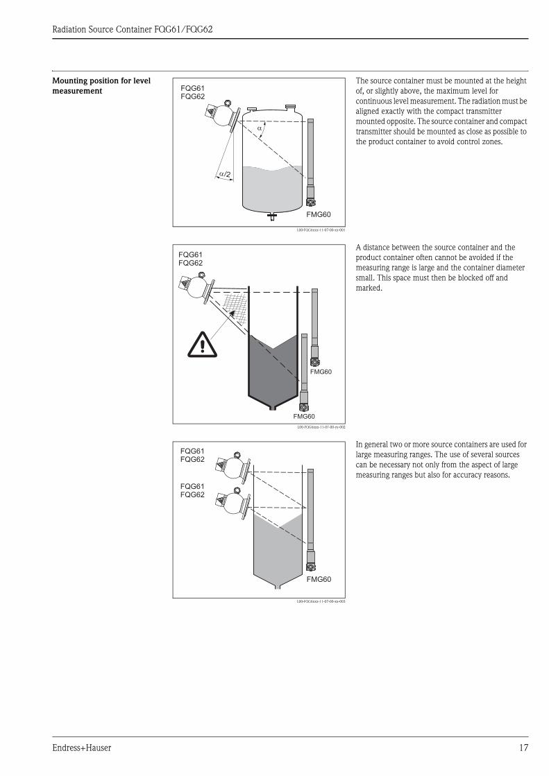
Mounting position for level
measurement
L00-FQG6xxx-11-07-00-xx-001
The source container must be mounted at the height
of, or slightly above, the maximum level for
continuous level measurement. The radiation must be
aligned exactly with the compact transmitter
mounted opposite. The source container and compact
transmitter should be mounted as close as possible to
the product container to avoid control zones.
�/2
�
FMG60
FQG61FQG62
L00-FQG6xxx-11-07-00-yy-002
A distance between the source container and the
product container often cannot be avoided if the
measuring range is large and the container diameter
small. This space must then be blocked off and
marked.
FMG60
FMG60
FQG61FQG62
L00-FQG6xxx-11-07-00-xx-003
In general two or more source containers are used for
large measuring ranges. The use of several sources
can be necessary not only from the aspect of large
measuring ranges but also for accuracy reasons.
FMG60
FQG61FQG62
FQG61FQG62
Endress+Hauser 17

Radiation Source Container FQG61/FQG62
Mounting position for level
limit detection
Mounting position for density
measurement
The most constant conditions for density measurement in pipes are achieved if the unit is mounted on vertical
pipe lines and the feed direction is from bottom to top. If only horizontal pipes are accessible, the path of the
ray should also be arranged horizontally to reduce the influence of air bubbles and build-up.
In order to achieve a longer path of the radiation through the medium and thus a larger measuring effect, a
diagonal beam or a measuring path can be applied:
L00-FQG6xxx-11-07-00-yy-005
1: Vertical beam; 2: Diagonal beam; 3: Measuring path
The following accessories are available for mounting the radiation source container and the FMG60 compact
transmitter to pipes:
• Clamping device FHG61 (→ ä 38)
• Measuring path FHG62 (→ ä 39)
L00-FQG6xxx-11-07-00-xx-004
The version of the radiation source container with the
angle of emission α = 5° is recommended for level
limit detection. If larger angles of emission (20° or
40°) are used, ensure that the ray is horizontal. For
this purpose, mount the radiation source container in
such a way that the eyelet is positioned horizontally.FMG60
FQG61FQG62
1 2 3
FQG61FQG62
FMG60
FQG61FQG62
FMG60
FQG61FQG62
FMG60
18 Endress+Hauser

Radiation Source Container FQG61/FQG62
Orientation of the fireproof
version
Orientation A (recommended)
The source container is mounted with the compensation compartment on the top. In case of fire only the
emission channel will be closed by the liquefied lead.
! Note!
After a fire, the screening is slightly reduced in the upper area of the container.
L00-FQG6xxx-11-07-00-xx-005
1: Level measurement; 2: Level limit detection
Orientation B (only if orientation A is impossible due to lack of space)
The source container is mounted with the compensation compartment at the bottom or in lateral position. In
case of fire the emission channel and the compensation compartment will be filled with the liquefied lead.
! Note!
After a fire, the screening will be strongly reduced in the upper area of the source container.
L00-FQG6xxx-11-07-00-xx-006
1: Level measurement; 2: Level limit detection
1 2
40°/
20°
5°
1 2
40°/
20°
5°
Endress+Hauser 19

Radiation Source Container FQG61/FQG62
Mounting device (supplied by
customer)
A mounting plate or L-profiles can be used for mounting of the radiation source container:
L00-QGxxxxx-11-07-00-yy-010
1: Example of a mounting plate; 2. Example of L-profiles
! Note!
The mounting flange of FQG61 and FQG62 is compatible with:
• DN100 PN16
• ANSI 4" 150lbs
Toothed lock washers
Torque for the mounting
screws
8x4
5°
C
ø120
(4.7
)
D
A
B
1 2
mm (inch)
A
B
D
A mm (inch)
B mm (inch)
C mm (inch)
D mm (inch)
EN
68.9 (2.7)
166.3 (6.5)
180.0 (7.1)
18.0 (0.7)
ANSI
72.9 (2.9)
176.0 (6.9)
190.5 (7.5)
19.1 (0.75)
The device must be integrated in the potential
equalization of the plant. In order to ensure electrical
contact between the radiation source container and
the mounting support, the supplied toothed lock
washers have to be installed at two of the mounting
screws according to the picture on the right.
" Caution!
Apply the prescribed torque for the mounting screws.
Make sure that the bolts have electrical contact to the
potential equalization.L00-FQG6xxx-11-07-00-xx-008
Material Property class Coefficient of friction Torque
SS 70 0.14 50 to 140 Nm
Steel 8.8 0.14 50 to 140 Nm
20 Endress+Hauser
Radiation Source Container FQG61/FQG62
Post-installation check Measuring the local dose rate
The local dose rate in the vicinity of the source container and the detector must be measured immediately after
it has been mounted.
" Caution!
Depending on the installation, radiation can also occur outside the actual beam-emitting channel through
scattering. In such cases it must be screened by the use of additional lead or steel sheeting. Render or mark all
control and exclusion areas as prohibited for unauthorised entry.
Behavior on empty process vessel
" Caution!
After the skilled mounting, the control area of the empty tank has to be measured. If it is necessary, this area
must be blocked off and marked. If there is an entry into the interior space of the tank, it has to be closed and
marked with a sign "radioactive". The entry is only allowed after checking all safety regulation by the
responsible radiation protection officer.
If maintenance operations are carried out in or at the vessel, it is mandatory to switch the radiation OFF.
Endress+Hauser 21

Radiation Source Container FQG61/FQG62
Connection of the pneumatic actuator
! Note!
This chapter is only valid for radiation source containers with pneumatic actuator.
(In the product structure: Feature 020, options K, L, M and N)
" Caution!
The pneumatic actuator may only be put into operation after the radiation source container has been mounted.
Compressed-air connection
L00-FQG6xxxx-04-00-00-xx-005
1: Throttle check valve for compressed air connection;
2: Vent;
3: Terminal box for connection of the proximity switches;
4: Cable glands for cable diameter 5 mm to 10 mm (0,2" to 0,4");
5: Connector for potential equalization
The compressed air line is connected to the throttle check valve.
" Caution!
The throttle check valve is adjusted at the factory and secured with screw lock - do not change!
1
3
2
EINON
AUSOFF
4 4
5
22 Endress+Hauser
Radiation Source Container FQG61/FQG62
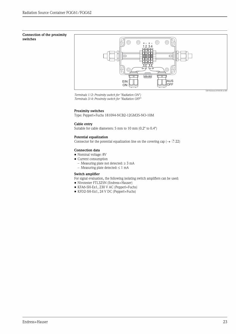
Connection of the proximity
switches
L00-FQG6xxxx-04-00-00-xx-004
Terminals 1/2: Prosimity switch for "Radiation ON";
Terminals 3/4: Proximity switch for "Radiation OFF"
Proximity switches
Type: Pepperl+Fuchs 181094-NCB2-12GM35-NO-10M
Cable entry
Suitable for cable diameters: 5 mm to 10 mm (0.2" to 0.4")
Potential equalization
Connector for the potential equalization line on the covering cap (→ ä 22)
Connection data
• Nominal voltage: 8V
• Current consumption
– Measuring plate not detected: ≥ 3 mA
– Measuring plate detected: ≤ 1 mA
Switch amplifier
For signal evaluation, the following isolating switch amplifiers can be used:
• Nivotester FTL325N (Endress+Hauser)
• KFA6-SH-Ex1, 230 V AC (Pepperl+Fuchs)
• KFD2-SH-Ex1, 24 V DC (Pepperl+Fuchs)
EINON
AUSOFF
1 2 3 4
br bl br bl
+ - + -
Endress+Hauser 23

Radiation Source Container FQG61/FQG62
Commissioning Before commissioning, the compressed air supply has to be connected and the padlock (1) on the top of the
instrument has to be removed. In case of revisions this padlock must be locked again in the OFF position. In
the meantime insert the padlock in the second padlock or keep it at a place outside the installation.
The lower padlock (2) blocks access to the radiation source and must not be opened during normal operation.
L00-FQG6xxxx-04-00-00-xx-002
1: Padlock for securing the OFF position - remove when operating the pneumatic actuator
2: Padlock for securing the radiation source - must not be removed during normal operation
Reading the switch status
Technical data of the
pneumatic actuator
• Swivel range: 180 °
• Compressed air connection: G1/4
• Actuating pressure: 3.5 ... 6 bar (51 ... 87 psi)
• Reset by means of spring
• Required air quality: Class 5 according to ISO8573-1, pressure dew point 10 K below operating temperature
1
2
L00-FQGxxxxx-19-00-00-xx-012
The current switching state is marked by the visible
sign ("EIN - ON" or "AUS - OFF"). The currently
invalid sign is covered by the disc at the pneumatic
acutator.
" Caution!
Do not touch the indication window when the
actuator is pressurized.
24 Endress+Hauser
Radiation Source Container FQG61/FQG62
Operation: FQG6x - #A ...
Safety instructions for
switching on the radiation
• Before switching ON the radiation it is necessary to ensure that no personnel are within the area of the
radiation (or, indeed, inside the vessel).
• The radiation beam may only be switched ON by specially trained personnel.
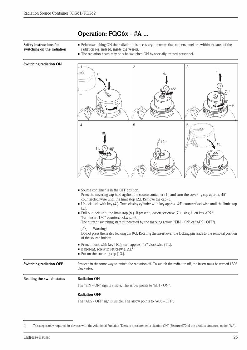
Switching radiation ON
• Source container is in the OFF position.
Press the covering cap hard against the source container (1.) and turn the covering cap approx. 45°
counterclockwise until the limit stop (2.). Remove the cap (3.).
• Unlock lock with key (4.). Turn closing cylinder with key approx. 45° counterclockwise until the limit stop
(5.).
• Pull out lock until the limit stop (6.). If present, loosen setscrew (7.) using Allen key AF5.4)
Turn insert 180° counterclockwise (8.).
The current switching state is indicated by the marking arrow ("EIN - ON" or "AUS - OFF").
# Warning!
Do not press the sealed locking pin (9.). Rotating the insert over the locking pin leads to the removal position
of the source holder.
• Press in lock with key (10.); turn approx. 45° clockwise (11.).
• If present, screw in setscrew (12.).4
• Put on the covering cap (13.).
Switching radiation OFF Proceed in the same way to switch the radiation off. To switch the radiation off, the insert must be turned 180°
clockwise.
Reading the switch status Radiation ON
The "EIN - ON" sign is visible. The arrow points to "EIN - ON".
Radiation OFF
The "AUS - OFF" sign is visible. The arrow points to "AUS - OFF".
13.
4.6.
45°5.7. *
12. *
8.180°
10.
45°11.
3.
1.1.
2.45°
4
2
5
3
6
1
9.
4) This step is only required for devices with the Additional Function "Density measurement> fixation ON" (Feature 670 of the product structure, option WA).
Endress+Hauser 25
Radiation Source Container FQG61/FQG62
Operation: FQG6x - #B ...
Safety instructions for
switching on the radiation
• Before switching ON the radiation it is necessary to ensure that no personnel are within the area of the
radiation (or, indeed, inside the vessel).
• The radiation beam may only be switched ON by specially trained personnel.
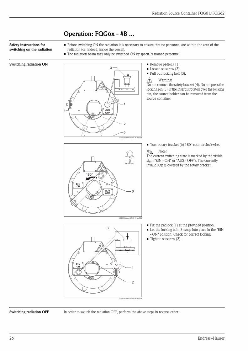
Switching radiation ON
Switching radiation OFF In order to switch the radiation OFF, perform the above steps in reverse order.
L00-FQGxxxxx-19-00-00-xx-003
• Remove padlock (1).
• Loosen setscrew (2).
• Pull out locking bolt (3).
# Warning!
Do not remove the safety bracket (4). Do not press the
locking pin (5). If the insert is rotated over the locking
pin, the source holder can be removed from the
source container
L00-FQGxxxxx-19-00-00-xx-004
• Turn rotary bracket (6) 180° counterclockwise.
! Note!
The current switching state is marked by the visible
sign ("EIN - ON" or "AUS - OFF"). The currently
invalid sign is covered by the rotary bracket.
L00-FQGxxxxx-19-00-00-xx-005
• Fix the padlock (1) at the provided position.
• Let the locking bolt (3) snap into place in the "EIN
- ON" position. Check for correct locking.
• Tighten setscrew (2).
1
2
3
4
5
180°
6
1
2
3
26 Endress+Hauser

Radiation Source Container FQG61/FQG62
Operation: FQG6x - #C ...
Safety instructions for
switching on the radiation
• Before switching ON the radiation it is necessary to ensure that no personnel are within the area of the
radiation (or, indeed, inside the vessel).
• The radiation beam may only be switched ON by specially trained personnel.
Switching radiation ON
Switching radiation OFF In order to switch the radiation OFF, perform the above steps in reverse order.
L00-FQGxxxxx-19-00-00-xx-006
• Remove padlock (1).
• Loosen setscrew (2).
# Warning!
Do not press the locking pin (3). If the insert is rotated
over the locking pin, the source holder can be
removed from the source container.
L00-FQGxxxxx-19-00-00-xx-007
• Turn rotary bracket (4) 180° counterclockwise.
! Note!
The current switching state is marked by the visible
sign ("EIN - ON" or "AUS - OFF"). The currently
invalid sign is covered by the rotary bracket.
L00-FQGxxxxx-19-00-00-xx-008
• Secure the "ON" switching state with the padlock
(1) at the provided position.
• Tighten setscrew (2).
1
2
3
180°
4
12
Endress+Hauser 27
Radiation Source Container FQG61/FQG62
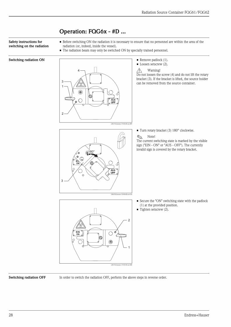
Operation: FQG6x - #D ...
Safety instructions for
switching on the radiation
• Before switching ON the radiation it is necessary to ensure that no personnel are within the area of the
radiation (or, indeed, inside the vessel).
• The radiation beam may only be switched ON by specially trained personnel.
Switching radiation ON
Switching radiation OFF In order to switch the radiation OFF, perform the above steps in reverse order.
L00-FQGxxxxx-19-00-00-xx-009
• Remove padlock (1).
• Loosen setscrew (2).
# Warning!
Do not loosen the screw (4) and do not lift the rotary
bracket (3). If the bracket is lifted, the source holder
can be removed from the source container.
L00-FQGxxxxx-19-00-00-xx-010
• Turn rotary bracket (3) 180° clockwise.
! Note!
The current switching state is marked by the visible
sign ("EIN - ON" or "AUS - OFF"). The currently
invalid sign is covered by the rotary bracket.
L00-FQGxxxxx-19-00-00-xx-008
• Secure the "ON" switching state with the padlock
(1) at the provided position.
• Tighten setscrew (2).
1
2
3
4
3
180°
1
2
28 Endress+Hauser

Radiation Source Container FQG61/FQG62
Maintenance and Inspection
Cleaning Clean the device in periodical intervals. When doing so, observe the following:
• Clean the device from substances which may have impact on safety functions.
• Keep labels in legible condition.
• Clean the adhesive labels and - for the versions with pneumatic actuator - the terminal box only wet with
water.
" Caution!
When cleaning the device, the safety instructions (→ ä 3 ff) have to be observed.
Maintenance and Inspection In designated use, operated under the specified ambient and operating conditions, no maintenance of the
device is required.
Within the framework of routine inspections of the plant the following checks are recommended:
• visual check regarding corrosion of housing, weld seams, outer parts of source insert and lock(s), toothed
lock washers
• check of the movability of the source holder (on/off function)
• visual check of the readability of the labels and the condition of the warning symbols
• check of the stability and position of the source holder
" Caution!
If there is any doubt about correct function or proper condition of the device, immediately contact the
responsible radiation safety officer for advice.
" Caution!
Non-routine repair or maintenance must be performed by the gauge manufacturer or distributor or - in the
USA - by a person specially authorized by NRC or an Agreement State.
Measures in case of corrosion
If considerable corrosion is visible at the housing, measure the radiation level around the device. If values occur
exceeding the normal operation level, cordon off the area and contact the responsible radiation safety officer
for instructions immediately.
" Caution!
In every case corroded devices and toothed lock washers should be exchanged as soon as possible.
Source containers with corroded interlocks or source holder require immediate exchange.
Endress+Hauser 29
Radiation Source Container FQG61/FQG62
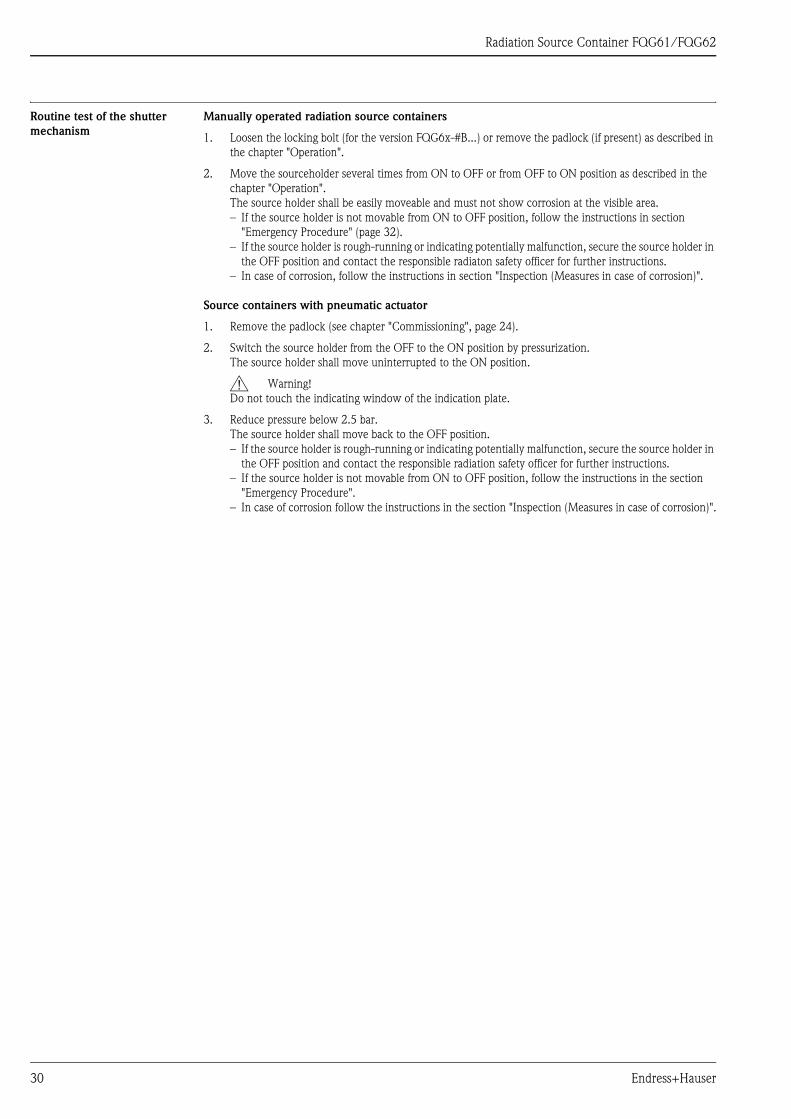
Routine test of the shutter
mechanism
Manually operated radiation source containers
1. Loosen the locking bolt (for the version FQG6x-#B...) or remove the padlock (if present) as described in
the chapter "Operation".
2. Move the sourceholder several times from ON to OFF or from OFF to ON position as described in the
chapter "Operation".
The source holder shall be easily moveable and must not show corrosion at the visible area.
– If the source holder is not movable from ON to OFF position, follow the instructions in section
"Emergency Procedure" (page 32).
– If the source holder is rough-running or indicating potentially malfunction, secure the source holder in
the OFF position and contact the responsible radiaton safety officer for further instructions.
– In case of corrosion, follow the instructions in section "Inspection (Measures in case of corrosion)".
Source containers with pneumatic actuator
1. Remove the padlock (see chapter "Commissioning", page 24).
2. Switch the source holder from the OFF to the ON position by pressurization.
The source holder shall move uninterrupted to the ON position.
# Warning!
Do not touch the indicating window of the indication plate.
3. Reduce pressure below 2.5 bar.
The source holder shall move back to the OFF position.
– If the source holder is rough-running or indicating potentially malfunction, secure the source holder in
the OFF position and contact the responsible radiation safety officer for further instructions.
– If the source holder is not movable from ON to OFF position, follow the instructions in the section
"Emergency Procedure".
– In case of corrosion follow the instructions in the section "Inspection (Measures in case of corrosion)".
30 Endress+Hauser

Radiation Source Container FQG61/FQG62
Routine leak test procedure The capsule enclosing the radiation source must be checked for leaks at regular intervals. Leak tests shall be
performed according to the interval specified by the authority or handling authorization.
! Note!
Leak tests are not only required as routine checkup but also whenever an incident occurs that may damage the
sealed source or the shielding. In such a case the leak test procedure shall be defined by the responsible radia-
tion safety officer observing the applicable regulations and considering the source container and all involved
parts of the process vessel.
The leak test shall be conducted as soon as possible after the incident.
The leak test procedure described below is intended for the following situations:
• as routine leak test procedure during continuous operation
• as routine leak test procedure during continuous storage of the radiation source container
• when placing back the radiation source container into operation after storage.
Leak test procedure
Leak tests shall be performed by a person or an organization authorized to provide leak test services or using a
leak test kit supplied by an organization authorized to provide leak test kits. Leak test kits shall be used
according to its supplier´s instructions. Records of the leak test results shall be maintained.
Perform following procedure unless otherwise instructed:
L00-FQGxxxxx-19-00-00-xx-013
Wiping surfaces for the leak test
1. Wipe at least at the following positions:
– FQG6x-#A/B/C/D...: along the gap between the source holder and the housing
– FQG6x-#K/L/M/N...: along the thread of the proximity switches and the three annular gaps of the
cylinder housing.
This may be conducted when the source holder is in ON or OFF position at manually operated types. At
types with pneumatic actuator, secure the OFF position with the padlock before conducting the leak test.
2. Have the samples analized by an authorized organization. A source is considered to be leaking if more
than 185 Bq (5 nCi) is detected on a leak test sample.
! Note!
This limit value is valid for the US. National regulations may define other limits.
In case of an indeed leaking source:
• Contact the responsible radiation safety officer for instructions
• Take appropriate measures to control a potential spread of radioactive contamination from the source. Secure
the source.
• Notify the authority of the fact that a leaking source has been detected.
FQG6x-#A... FQG6x-#B...
FQG6x-#C... FQG6x-#D...
FQG6x-#K/L/M/N...
Endress+Hauser 31

Radiation Source Container FQG61/FQG62
Emergency procedure
Objective and overview This emergency procedure shall be put into effect immediately to secure an area in the interests of protecting
personnel where an exposed source is known, or suspected, to exist.
Such an emergency exists when a radioisotope is exposed either by it becoming separated from the source
container or a source holder cannot be put into OFF position.
This procedure will safeguard the personnel until the responsible radiation safety officer can attend site and
advise on corrective action.
The custodian of the radioactive source (the customer's designated "authorized person") is responsible for
observing this procedure.
Emergency procedure 1. Determine the unsafe area by on-site measurement.
2. Cordon off the concerned area by yellow tape or rope and post international radiation warning signs.
The radiation source container can not be switched to the "OFF" position
In this case the radiation source container must be unbolted from its mounting position.
Point the emission channel towards a very thick wall (e.g. steel or lead) or mount a blind flange in front of the
emission channel.
Personnel should at all times be behind the source housing, not in front of the emission channel (flange of the
FQG61/FQG62).
The lifting eye on the housing should facilitate safe handling.
The radiation source has escaped from the source container
In this case, the radiation source must be placed at a safe location or additional shielding must be applied.
The source should only be handled via pliers or tongs and held as far away from the body as possible.
The time needed for the transport should be estimated and minimized by rehearsal without radiation source
prior to execution.
Notification to authority 1. Make necessary notifications to local authorities within 24 h.
2. After thorough assessment of the situation, the responsible radiation safety officer, in conjunction with
local authorities, shall agree a remedy to the specific problem.
! Note!
National regulations may require other procedures and reporting obligations.
32 Endress+Hauser

Radiation Source Container FQG61/FQG62
Procedures after termination of the application
Internal measures As soon as a radiometric measuring device is no longer required, the radiation source on the source container
must be switched off. The source container shall be removed in accordance with all relevant regulations and
saved in a lockable room having no through traffic. The responsible authorities shall be informed of these
measures. The access to the storage room shall be measured out and signed. The radiation safety officer is
responsible for protecting against theft. The radiation source in the source container must not be scrapped with
the other parts of the plant. It should be returned as quickly as possible.
" Caution!
Removal of the source container may only be carried out by supervised personnel, who have been specially
trained in radiation procedures according to local regulations or handling approval. Ensure that the contents of
the handling approval is valid. Local conditions are to be observed.
All work must be carried out as quickly as possible and from a distance as large as possible (shielding!). Safety
procedures must also be carried out to protect personnel from all possible risks.
The disassembly of the source container can only be executed during OFF position.
Make sure, the OFF position is secured with a padlock.
Return Federal Republic of Germany
Contact your Endress+Hauser Sales Centre to organise the return of the radiation source for inspection with a
view to reuse or recycling by Endress+Hauser.
Other countries
Contact your Endress+Hauser Sales Centre or the appropriate authority to find a way of returning the radiation
source nationally. If return is not possible domestically, the further procedure must be agreed with the sales
centre concerned. The destination airport for potential returns is Frankfurt, Germany.
Conditions
The following conditions must be met before returning the material:
• An inspection certificate no more than three months old confirming the leak-tightness of the radiation source
must be in the possession of Endress+Hauser (wipe test certificate).
• The serial number of the source capsule, type of radiation source (60Co or 137Cs), activity and model of
radiation source must be specified. This data may be found in the documents supplied with the radiation
source.
• The material must be returned in type-tested type-A packaging (IATA rules).
Order code: 52011467
Dimensions: 400 mm x 400 mm x 650 mm (16" x 16" x 26")
! Note!
The type-A-labelling at the radiation container itself is invalid for a return of the device.
Endress+Hauser 33

Radiation Source Container FQG61/FQG62
Ordering information
Product structure FQG61 015 Licence
AA Not necessary
AB AERB Type approval certificate, India
AC CNSC Radiation Device Certificate, Canada
AD NRC Device Registration General Licence, USA
AE NRC Device Registration, USA
AF GOST, Russia
AG Device Registration Licence of (Territory) , Australia
YY Special version, TSP-no. to be spec.
020 Version
A Cylinder lock fixation ON/OFF + covering cap
B Rotary bracket + locking bolt ON + padlock fixation OFF
C Padlock fixation ON/OFF + rotary bracket
D Padlock fixation ON/OFF + O-ring double gasket > higher protection dust/humidity + rotary bracket
K Pneum. actuator, non Ex + cylinder lock fixation OFF
L Pneum. acutator, Atex + cylinder lock fixation OFF + ATEX II 2G
M Pneum. actuator, non Ex + O-ring double gasket > higher protection dust/humidity + padlock fixation OFF
N Pneum. actuator, Atex + O-ring double gasket > higher protection dust/humidity + padlock fixation OFF +
ATEX II 2 G
9 Special version, TSP-no. to be spec.
040 Prepared for Source Loading
V Provided by customer
1 Caesium 137
2 Cobalt 60
100 Prepared for Source Activity
AA 3,7 MBq/0,1 mCi
AB 7,4 MBq/0,2 mCi
AC 18,5 MBq/0,5 mCi
AD 37 MBq/1 mCi
AE 74 MBq/2 mCi
AF 110 MBq/3 mCi
AG 185 MBq/5 mCi
AH 370 MBq/10 mCi
AK 740 MBq/20 mCi
AL 1,1 GBq/30 mCi
AM 1,85 GBq/50 mCi
AN 3,7 GBq/100 mCi
AP 7,4 GBq/200 mCi
AR 11 GBq/300 mCi
AT 18,5 GBq/500 mCi
AW 29,6 GBq/800 mCi
BB 37 GBq/1000 mCi
VV not specified
YY Special version, TSP-no. to be spec.
200 Prepared for Source Capsule Type
A1 Nipple d=6,4x16mm, capsule VZ79/1
A2 Nipple d=6,4x16mm, capsule VZ64/1
B1 Thread M4 d=6,4x17,6mm, capsule VZ1508/2
B2 Thread M4 d=6,4x17,6mm, capsule VZ1486/3
C1 Nipple d=8x19mm, capsule VZ357/2
D1 Thread M4 d=8x19mm, capsule VZ3579
F1 Cylinder d=8,05x12,3, capsule X.9
J1 Cylinder d=6x10, capsule IGI-Z-3
L1 Cylinder d=8x12, capsule IGI-Z-4
Y9 Special version, TSP-no. to be spec.
34 Endress+Hauser
Radiation Source Container FQG61/FQG62
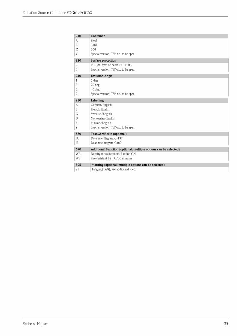
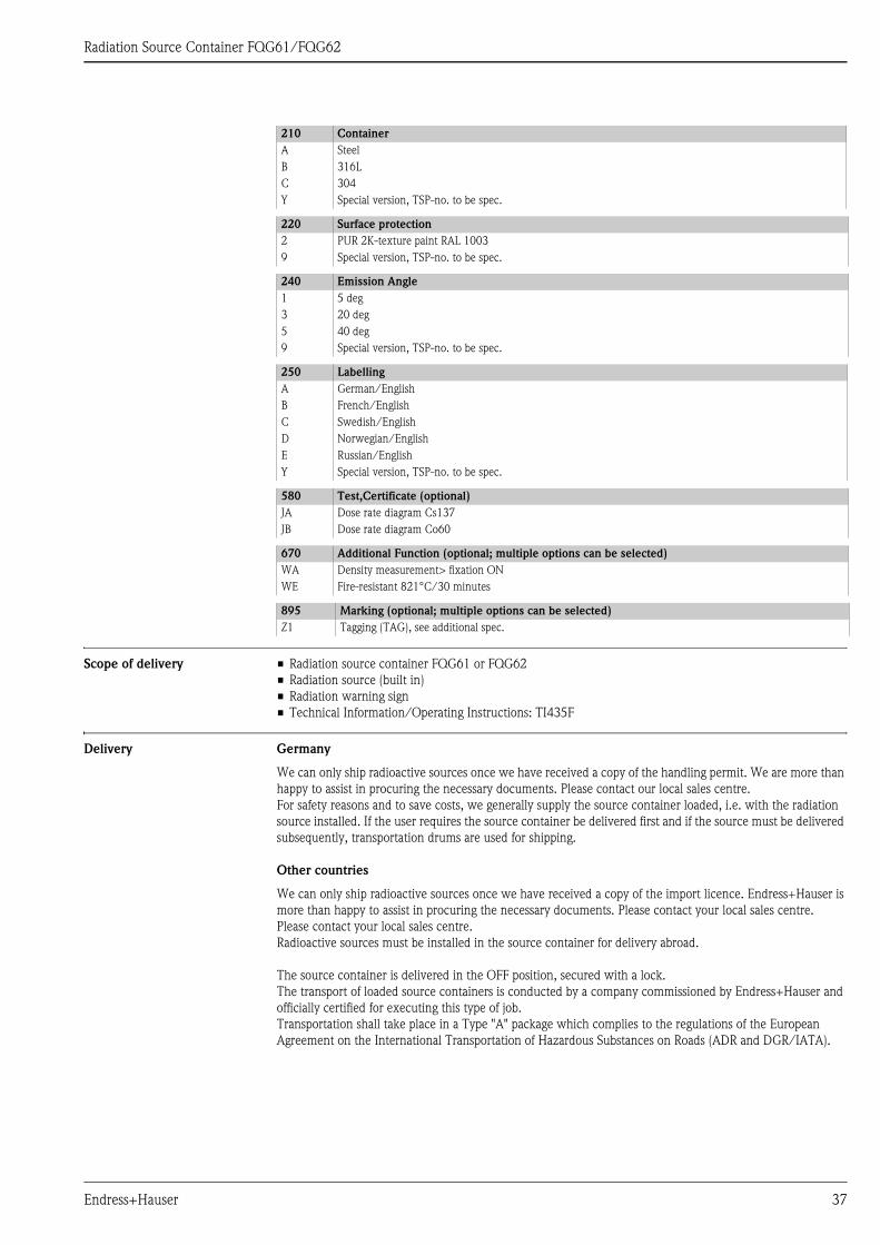
210 Container
A Steel
B 316L
C 304
Y Special version, TSP-no. to be spec.
220 Surface protection
2 PUR 2K-texture paint RAL 1003
9 Special version, TSP-no. to be spec.
240 Emission Angle
1 5 deg
3 20 deg
5 40 deg
9 Special version, TSP-no. to be spec.
250 Labelling
A German/English
B French/English
C Swedish/English
D Norwegian/English
E Russian/English
Y Special version, TSP-no. to be spec.
580 Test,Certificate (optional)
JA Dose rate diagram Cs137
JB Dose rate diagram Co60
670 Additional Function (optional; multiple options can be selected)
WA Density measurement> fixation ON
WE Fire-resistant 821°C/30 minutes
895 Marking (optional; multiple options can be selected)
Z1 Tagging (TAG), see additional spec.
Endress+Hauser 35
Radiation Source Container FQG61/FQG62
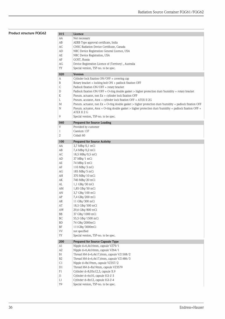
Product structure FQG62 015 Licence
AA Not necessary
AB AERB Type approval certificate, India
AC CNSC Radiation Device Certificate, Canada
AD NRC Device Registration General Licence, USA
AE NRC Device Registration, USA
AF GOST, Russia
AG Device Registration Licence of (Territory) , Australia
YY Special version, TSP-no. to be spec.
020 Version
A Cylinder lock fixation ON/OFF + covering cap
B Rotary bracket + locking bolt ON + padlock fixation OFF
C Padlock fixation ON/OFF + rotary bracket
D Padlock fixation ON/OFF + O-ring double gasket > higher protection dust/humidity + rotary bracket
K Pneum. actuator, non Ex + cylinder lock fixation OFF
L Pneum. acutator, Atex + cylinder lock fixation OFF + ATEX II 2G
M Pneum. actuator, non Ex + O-ring double gasket > higher protection dust/humidity + padlock fixation OFF
N Pneum. actuator, Atex + O-ring double gasket > higher protection dust/humidity + padlock fixation OFF +
ATEX II 2 G
9 Special version, TSP-no. to be spec.
040 Prepared for Source Loading
V Provided by customer
1 Caesium 137
2 Cobalt 60
100 Prepared for Source Activity
AA 3,7 MBq/0,1 mCi
AB 7,4 MBq/0,2 mCi
AC 18,5 MBq/0,5 mCi
AD 37 MBq/1 mCi
AE 74 MBq/2 mCi
AF 110 MBq/3 mCi
AG 185 MBq/5 mCi
AH 370 MBq/10 mCi
AK 740 MBq/20 mCi
AL 1,1 GBq/30 mCi
AM 1,85 GBq/50 mCi
AN 3,7 GBq/100 mCi
AP 7,4 GBq/200 mCi
AR 11 GBq/300 mCi
AT 18,5 GBq/500 mCi
AW 29,6 GBq/800 mCi
BB 37 GBq/1000 mCi
BC 55,5 GBq/1500 mCi
BD 74 GBq/2000mCi
BF 111GBq/3000mCi
VV not specified
YY Special version, TSP-no. to be spec.
200 Prepared for Source Capsule Type
A1 Nipple d=6,4x16mm, capsule VZ79/1
A2 Nipple d=6,4x16mm, capsule VZ64/1
B1 Thread M4 d=6,4x17,6mm, capsule VZ1508/2
B2 Thread M4 d=6,4x17,6mm, capsule VZ1486/3
C1 Nipple d=8x19mm, capsule VZ357/2
D1 Thread M4 d=8x19mm, capsule VZ3579
F1 Cylinder d=8,05x12,3, capsule X.9
J1 Cylinder d=6x10, capsule IGI-Z-3
L1 Cylinder d=8x12, capsule IGI-Z-4
Y9 Special version, TSP-no. to be spec.
36 Endress+Hauser
Radiation Source Container FQG61/FQG62
Scope of delivery • Radiation source container FQG61 or FQG62
• Radiation source (built in)
• Radiation warning sign
• Technical Information/Operating Instructions: TI435F
Delivery Germany
We can only ship radioactive sources once we have received a copy of the handling permit. We are more than
happy to assist in procuring the necessary documents. Please contact our local sales centre.
For safety reasons and to save costs, we generally supply the source container loaded, i.e. with the radiation
source installed. If the user requires the source container be delivered first and if the source must be delivered
subsequently, transportation drums are used for shipping.
Other countries
We can only ship radioactive sources once we have received a copy of the import licence. Endress+Hauser is
more than happy to assist in procuring the necessary documents. Please contact your local sales centre.
Please contact your local sales centre.
Radioactive sources must be installed in the source container for delivery abroad.
The source container is delivered in the OFF position, secured with a lock.
The transport of loaded source containers is conducted by a company commissioned by Endress+Hauser and
officially certified for executing this type of job.
Transportation shall take place in a Type "A" package which complies to the regulations of the European
Agreement on the International Transportation of Hazardous Substances on Roads (ADR and DGR/IATA).
210 Container
A Steel
B 316L
C 304
Y Special version, TSP-no. to be spec.
220 Surface protection
2 PUR 2K-texture paint RAL 1003
9 Special version, TSP-no. to be spec.
240 Emission Angle
1 5 deg
3 20 deg
5 40 deg
9 Special version, TSP-no. to be spec.
250 Labelling
A German/English
B French/English
C Swedish/English
D Norwegian/English
E Russian/English
Y Special version, TSP-no. to be spec.
580 Test,Certificate (optional)
JA Dose rate diagram Cs137
JB Dose rate diagram Co60
670 Additional Function (optional; multiple options can be selected)
WA Density measurement> fixation ON
WE Fire-resistant 821°C/30 minutes
895 Marking (optional; multiple options can be selected)
Z1 Tagging (TAG), see additional spec.
Endress+Hauser 37

Radiation Source Container FQG61/FQG62
Accessories
Clamping device FHG61
L00-QGxxxxx-14-xx-xx-en-000
Product structure FHG61
010 Pipe diameter
A 50-220mm -> Installation instructions KA262F
B 200-420mm -> Installation instructions KA263F
C 50-220mm, 30deg diagonal radiation -> Installation instructions KA261F
D 400-620mm (in preparation)
Y Special version, to be specified
015 Mounting Clamp for Scintillator
A NaI, 50mm
B PVT, 200mm
C PVT, 400mm
D NaI, 50mm + cooling tube/collimator /
PVT, 200mm/400mm + cooling tube
Y Special version, to be specified
020 Material
1 316L
9 Special version, to be specified
FHG61 - complete product designation
diagonal beam 30°radial beam
additionalshieldingif required
38 Endress+Hauser

Radiation Source Container FQG61/FQG62
Measuring path FHG62
L00-FQG6xxxx-14-xx-xx-en-001
! Note!
For details refer to the Installation Instructions SD540F.
Product structure FHG62
FMG60
QG020/QG100FQG61/FQG62
additionalshieldingif required
010 Shape Measuring Pipe
A S-shaped
B U-shaped
Y Special version, to be specified
020 Length Measuring Path
1 350mm
9 Special version, to be specified
030 Pipe Diameter
A1 DN25, PN16, 316Ti
A2 DN25, PN16, PP
A3 DN25, PN16, PVDF
B1 DN32, PN16, 316Ti
B2 DN32, PN16, PP
B3 DN32, PN16, PVDF
C1 DN40, PN16, 316Ti
C2 DN40, PN10, PP
C3 DN40, PN16, PVDF
D1 DN50, PN16, 316Ti
D2 DN50, PN10, PP
D3 DN50, PN16, PVDF
E1 DN65, PN16, 316Ti
E2 DN65, PN10, PP
E3 DN65, PN16, PVDF
F1 DN80, PN16, 316Ti
F2 DN80, PN10, PP
F3 DN80, PN16, PVDF
Y9 Special version, to be specified
040 Material Clamping Device
A 304
Y Special version, to be specified
FHG62 - complete product designation
Endress+Hauser 39
Radiation Source Container FQG61/FQG62
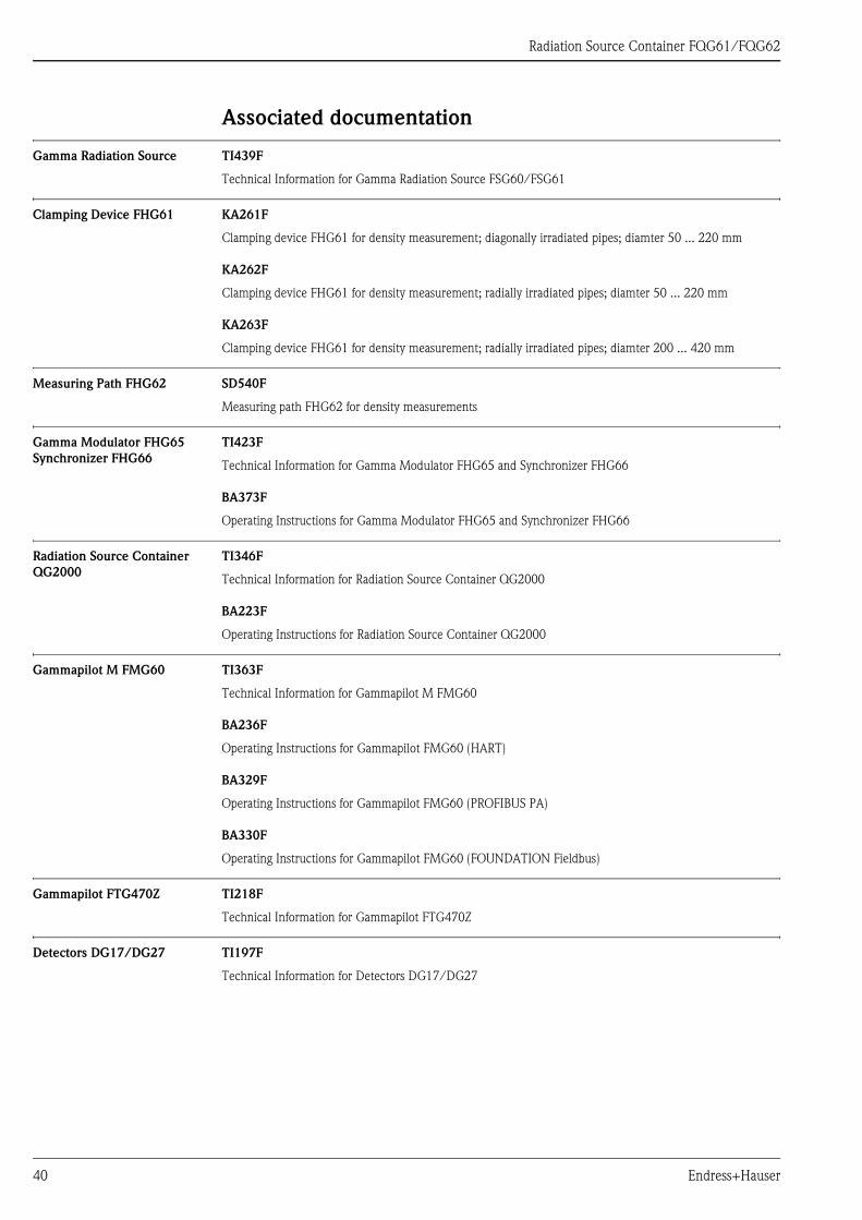
Associated documentation
Gamma Radiation Source TI439F
Technical Information for Gamma Radiation Source FSG60/FSG61
Clamping Device FHG61 KA261F
Clamping device FHG61 for density measurement; diagonally irradiated pipes; diamter 50 ... 220 mm
KA262F
Clamping device FHG61 for density measurement; radially irradiated pipes; diamter 50 ... 220 mm
KA263F
Clamping device FHG61 for density measurement; radially irradiated pipes; diamter 200 ... 420 mm
Measuring Path FHG62 SD540F
Measuring path FHG62 for density measurements
Gamma Modulator FHG65
Synchronizer FHG66
TI423F
Technical Information for Gamma Modulator FHG65 and Synchronizer FHG66
BA373F
Operating Instructions for Gamma Modulator FHG65 and Synchronizer FHG66
Radiation Source Container
QG2000
TI346F
Technical Information for Radiation Source Container QG2000
BA223F
Operating Instructions for Radiation Source Container QG2000
Gammapilot M FMG60 TI363F
Technical Information for Gammapilot M FMG60
BA236F
Operating Instructions for Gammapilot FMG60 (HART)
BA329F
Operating Instructions for Gammapilot FMG60 (PROFIBUS PA)
BA330F
Operating Instructions for Gammapilot FMG60 (FOUNDATION Fieldbus)
Gammapilot FTG470Z TI218F
Technical Information for Gammapilot FTG470Z
Detectors DG17/DG27 TI197F
Technical Information for Detectors DG17/DG27
40 Endress+Hauser
Radiation Source Container FQG61/FQG62
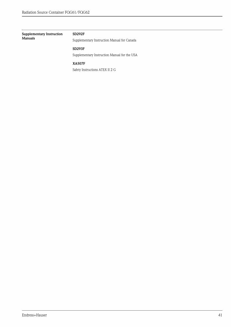
Supplementary Instruction
Manuals
SD292F
Supplementary Instruction Manual for Canada
SD293F
Supplementary Instruction Manual for the USA
XA507F
Safety Instructions ATEX II 2 G
Endress+Hauser 41

Radiation Source Container FQG61/FQG62
Manufacturer Declaration
Radiation Source Container
xxxxxxx
42 Endress+Hauser

Radiation Source Container FQG61/FQG62
Manufacturer Declaration
Packaging
Endress+Hauser 43
Instruments International
Endress+Hauser
Instruments International AG
Kaegenstrasse 2
4153 Reinach
Switzerland
Tel. +41 61 715 81 00
Fax +41 61 715 25 00
www.endress.com
TI435F/00/en/09.10
71122562
FM+SGML 6.0 ProMoDo
71122562