Technical handbook - Röraframleiðsla
261
Technical handbook TH170201EN TABLE OF CONTENT Chapter 1 | Set Pipes general Chapter 2 | Pre-insulated single pipes Chapter 3 | Pre-insulated double pipes Chapter 4 | Pre-insulated Flexible pipes Chapter 5 | Jointing material Chapter 6 | Leakage detection systems Chapter 7 | Installation instructions Chapter 8 | Documents/tables
Transcript of Technical handbook - Röraframleiðsla

Technical handbook
TH170201EN
TABLE OF CONTENT
Chapter 1 | Set Pipes general
Chapter 2 | Pre-insulated single pipes
Chapter 3 | Pre-insulated double pipes
Chapter 4 | Pre-insulated Flexible pipes
Chapter 5 | Jointing material
Chapter 6 | Leakage detection systems
Chapter 7 | Installation instructions
Chapter 8 | Documents/tables

Technical handbook
TH170201EN
Chapter 1 | General information
1.0 – The company .............................................................................................. 1
1.1 – Introduction ............................................................................................... 2
1.2 – Quality ........................................................................................................ 3
1.3 – Application design ................................................................................... 3
1.4 – Product selection ..................................................................................... 3
1.5 – Standards .................................................................................................... 5
1.6 – Company locations .................................................................................. 6
TABLE OF CONTENT

Technical handbook
TH170201EN /// 1
CHAPTER 1.0 THE COMPANY
FIG. 1.0.1
Aerial photograph of Selfoss,
the hometown of Set Pipes
in Iceland
FIG. 1.0.2
Aerial photograph of Haltern
am See, the hometown of
Set Pipes in Germany
FIG. 1.0.3
Bending test device. Test
device made by Set Pipes
for accurate determination
of bending forces in flexible
district heating pipes
The company Steypuiðjan began its production with concrete pipes for sewage
in 1968. Ten years later the company changed its name to Set Pipes and began
manufacturing pre-insulated steel pipes and fittings for district heating networks.
In 1980 the production of PE casing pipes for insulated district heating pipes,
PE water pipes, PP snow-melting pipes, PVC cable conduit pipes and PVC
sewage- and drainage pipes began. In 2006 Set Pipes started production of
pre-insulated flexible coiled pipes for district heating. Set Pipes also supplies a wide
range of accessories and fittings from well-known producers within the market.
Set Pipes is a privately run family business and not on the stock market, despite the
huge success on the domestic and export markets in recent years.
The company has invested continuously towards internal technology and worked
on numerous development projects placing great emphasis on staff training and
education. Ensuring a strong team of qualified staff is by far the most important
resource of the company within the competition that prevails in the manufacturing of
pre-insulated pipes.
All production departments of Set Pipe companies, follow strict guidelines
regarding production methods, approved raw material, and trained personnel,
internal and external quality control to ensure good and uniform product quality
according to ISO 9001.
Continuous development in the research for environmentally friendly energy
solutions and greater emphasis on protecting and utilizing heat energy as much
as possible, allows Set Pipes the opportunity to participate in the protection of
nature and its resources. More effective building insulation is an important factor, and
the insulation quality of district heating lines are vital for energy efficiency, meaning
a significant reduction of emission and pollution.
FIG. 1.0.1 FIG. 1.0.2
FIG. 1.0.3
Technical handbook
TH170201EN /// 2
This book describes the properties of district heating pipes from Set Pipes and is
aimed to give further technical information regarding the product properties, handling
and installation of various district heating products.
DISCLAIMERAll efforts have been made to ensure all contents of this book are correct. However,
Set Pipes assume no responsibility, or liability due to errors. Calculations, designs
and graphs shown are only aimed to give a simplified idea of pipe line networks.
Please contact our technical department or specialized engineering services for
accurate calculations. Changes may be made to certain parts within the book and
will be published on the company’s web page: www.set.is, www.setpipes.de and
www.setpipes.com. All rights reserved.
CHAPTER 1.1 INTRODUCTION

Technical handbook
TH170201EN /// 3
CHAPTER 1.3 APPLICATION ASSUMPTIONS
Calculations and installation guidelines comply with the technical requirements of
the EN 13941, EN 253, EN 448 and EN 488 standards. Missing calculation factors in
EN 13941 can be determined conventionally.
All effort has been made to ensure instruction accuracy, for possible discrepancies
please inform at Set Pipes email address: [email protected]
A detailed understanding of equations and technical regulation is necessary when
calculations are made according to the following guidelines. They do not replace an
engineer’s assessment. Set Pipes is not responsible for the reader’s use of this book.
When choosing material for district heating systems, certain criteria must be
followed to ensure the correct choices for each application. The following table shows
characteristics of individual product categories:
CHAPTER 1.4PIPE SELECTION
TABLE 1.4.1Properties of each
product category
Product category
Temperature resistance CCOT
Maximum pressure
Estimated flow
Pre-insulated steel pipes 161°C 16 bar 0,300 - 560 l/s
Pre-insulated steel pipes with PIR foam 175°C 16 bar 0,300 - 440 l/s
EliSteel 120°C 16 bar 0,200 - 0,400 l/s
EliPex 95°C 6 and 10 bar 0,200 - 100 l/s
EliCopp 120°C 16 bar 0,100 - 0,400 l/s
Set Pipes guarantee quality standard and production monitoring to ensure
customers long lasting products. The success of the company is not only based on
its competent employers and working environment, but also in the product quality.
Set Pipes is certified in accordance to the ISO 9001 standard, which continually
monitors and manages quality through all operations of the production and
service. Various testing is carried out as well as regular auditing of the quality system.
Set Pipes monitors the utilization of raw material and recycles in accordance with
ISO 14001.
The following institutions are responsible for the certification and regulation of
Set Pipes.
CHAPTER 1.2 QUALITY

Technical handbook
TH170201EN /// 4
THE FOLLOWING FACTORS HAVE THE MOST IMPACT ON HEAT LOSS:
- Thermal conductivity of the insulation
- Insulation series
- Pipe laying and Trench work
- Water flow temperature
- Ground temperature
- Condition and density of the ground
Expansion has a significant effect on the service life of the district heating pipes. In
order to avoid undesirable expansion, the use of compensators or expansions loops
is advised. Thermal expansion in the steel pipe which can in turn damage the casing
pipe or insulation foam and is the leading cause of defects in district heating systems.
Expansion calculations are not needed for our flexible pipes.
CERTAIN CRITERIA SHOULD BE CONSIDERED FOR THE EXPANSION CALCULATION:
- Flow temperature
- Soil height above pipe
- Heating and cooling fluctuation throughout the service lifespan of the system
- Wall thickness of steel pipe
- Assembly of the fittings
The meaning of “CCOT” is the temperature stability of the foam over a period
of 30 years. Other points affect the lifespan of district heating systems, design in
accordance to conditions plays a vital role along with the handling of movement due
to thermal expansion.
Designing stages can be divided into four main groups:
Heating requirement, determination of pipe size Q [W]
Pressure drop determination Δp Pipe [Pa/m]
Heat loss determination q [W/m]
Expansion determination ΔL [m]
Set Pipes can assist with pipe dimension choices, cost estimates and heat loss
calculations. Generally, customers bring a calculated heat requirement from an
engineering specialist where the needs for the complete system have been
determined. If the heat loss and water need are not correctly determined and
calculated it can lead to colder water due to slower flow or too much pressure
drop due to incorrect pipe dimension.
The correct pipe dimension can be found once the heat requirement is determined.
Pressure drop is calculated between a range of 100 – 200 Pa/m for DN < 150 pipes
and 100 – 150 Pa/m for DN ≥ 150 pipes. (page 4).
This is a variable that influences the initial costs and pumping cost. Set Pipes can
supply customers with a program for determining the correct pipe dimension based
on heat output. Heat loss is a deciding factor in the design of district heating systems.

Technical handbook
TH170201EN /// 5
PRE-INSULATED DISTRICT HEATING PIPES FROM SET PIPES ARE MANUFACTURED IN ACCORDANCE TO THE FOLLOWING EUROPEAN STANDARDS:
EN 253 - District heating pipes – Pre-insulated bonded pipe systems for directly
buried hot water networks - Pipe assembly of steel service pipe, polyurethane
thermal insulation and outer casing of polyethylene.
EN 448 - District heating pipes –Pre-insulated bonded pipe systems for directly buried
hot water networks – Fitting assemblies of steel service pipes, polyurethane thermal
insulation and outer casing of polyethylene.
EN 488 - District heating pipes – Pre-insulated bonded pipe systems for directly
buried hot water networks - Steel valve assembly for steel service pipes,
polyurethane thermal insulation and outer casing of polyethylene.
EN 489 - District heating pipes –Pre-insulated bonded pipe systems for directly buried
hot water networks - Joint assembly for steel service pipes, polyurethane thermal
insulation and outer casing of polyethylene.
EN 13941 - Design and installation of pre-insulated bonded pipe systems for district heating.
EN 14419 - District heating pipes – Pre-insulated bonded pipe systems for directly
buried hot water networks – Surveillance systems.
EN 15698 - District heating pipes – Pre-insulated bonded twin pipe systems for directly
buried hot water networks.
EN ISO 9001 - Quality management systems.
EN ISO 14001 - Environmental management systems.
AGFW FW 401 - Design and installation of pre-insulated bonded pipes for district heat-
ing networks.
The standards listed above do not represent an exhaustive list, many other
standards relate to our product manufacturing in one way or another. Individual
countries have additional standards that Set Pipes can use in cooperation with the
customer. All information in this manual are based on the relevant EN standards.
CHAPTER 1.5STANDARDS

Technical handbook
TH170201EN /// 6
CHAPTER 1.6COMPANY LOCATIONS
ICELAND - SET EHF.
Eyravegur 41, 800 Selfoss
+354 480 2700
+354 482 2099
www.set.is / www.setpipes.com
GERMANY - SET PIPES GMBH
Zum Ikenkamp 8,
D-45721 Haltern Am See
+49 (0) 2364 508894-0
+49 (0) 2364 508894-9
www.setpipes.de

Technical handbook
TH170201EN
Chapter 2 | Pre-insulated single steel pipes
2.0 – Pre-insulated single steel pipes ........................................................... 1
2.1 – Application range ..................................................................................... 5
2.1.1 – Pressure loss ........................................................................................ 5
2.1.2 – Expansion ........................................................................................... 10
2.1.3 – Expansion force ............................................................................... 11
2.1.4 – Distance between expansions ................................................... 12
2.1.5 – Heat loss ............................................................................................ 16
2.2 – Transport and storage ......................................................................... 22
2.3 – Field work ................................................................................................ 24
2.3.1 – Cold laying without expansion ................................................. 25
2.3.2 – Cold laying with U & Z expansion ............................................ 27
2.3.3 – Expansion pads .............................................................................. 29
2.3.4 – Pre-heating ...................................................................................... 32
2.3.5 – Expansion joints ............................................................................. 34
2.3.6 – Conditions ........................................................................................ 34
2.3.7 – Trench ................................................................................................ 35
2.3.8 – Backfilling ......................................................................................... 37
2.3.9 – Anchors ............................................................................................. 38
2.3.10 – House connections ..................................................................... 39
2.3.11 – Steel welding ................................................................................ 40
2.3.12 – Curved Pipes ................................................................................. 41
2.9 – Product catalogue ................................................................................. 43
TABLE OF CONTENT

Technical handbook
TH170201EN /// 1
SPECIFICATIONPre-insulated single steel pipes are insulated with polyurethane foam (PUR and covered with
PE casing pipe. It is a rigid connection system, meaning a continuous connection between
the steel pipe, PUR-foam and casing pipe. The pipes can be delivered in 6, 12 and 16 m
lengths, dimensions from DN 20 – 800 in insulation series 1, series 2 and series 3. See
chapter 2.9 for detailed descriptions of dimensions and sizes. Set Pipes can also offer
insulation of other material not specified in the product catalogue. Please contact our
technical department for other requirements. In addition, pre-insulated steel pipes in sizes
from 20 – 28 mm produced in coils are available. All information about the flexible steel
pipes can be found in chapter 4 under EliSteel.
APPLICATION RANGEThis specification is made for pre-insulated steel pipes for district heating.
See table 1.4.1.
MATERIALSet Pipes requires that each of its suppliers meet the highest standards for all
material. All suppliers have to be certified according to ISO 9001 and they are
evaluated before further cooperation. The quality of incoming materials is tested
and documented before commencing the production process.
PROPERTIES FOR 6, 12 AND 16 M STEEL PIPES ACCORDING TO EN 253 Set Pipes only obtains steel pipes from certified suppliers. Upon request we provide
customers an inspection certificate regarding material.
Steel pipes and steel fittings are according to the following criteria:
CHAPTER 2.0PRE-INSULATED SINGLE STEEL PIPES
TECHNICAL REQUIREMENTS: P235GH TC1 according to EN 10217-2 and 5, > DN 100 P235TR1 according to EN 10217-1 DN 20 - 80
DIMENSIONS AND WALL THICKNESS: EN 10220
BEVELING: EN ISO 9692-1
INSPECTION CERTIFICATE: EN 10204-3,1
TABLE 2.0.1 Steel pipe EN 253
Other steel pipe material with different specifications are available upon request.
Please contact our technical department for other requirements.

Technical handbook
TH170201EN /// 2
PROPERTIES FOR 6, 12 AND 16M PUR INSULATION ACCORDING TO EN 253The polyurethane material PUR has an excellent insulation value, high pressure resistance
and is a long lasting insulation. The PUR-material is pentane-driven and has zero effect on
the ozone layer. The PUR-foam has a binding effect between the PUR material, steel pipes
and plastic casing which is the basis for the rigid district heating system. The below shows
the minimum characteristics of PUR material from Set Pipes.
TABLE 2.0.3 Main dimensions
for steel pipes
DN = Diameter Nominal
do = Outer diameter
t1 = Wall thickness - AGFW 401
t2 = Wall thickness - EN 253
TABLE 2.0.4 PUR material is according
to the following criteria:
DN do[mm]
t1[mm]
t2[mm]
20 26,9 2,6 2,0
25 33,7 2,6 2,3
32 42,4 3,2 2,6
40 48,3 3,2 2,6
50 60,3 3,2 2,9
65 76,1 3,2 2,9
80 88,9 3,2 3,2
100 114,3 3,6 3,6
125 139,7 3,6 3,6
150 168,3 4,0 4,0
200 219,1 4,5 4,5
250 273,0 5,0 5,0
300 323,9 5,6 5,6
350 355,6 5,6 5,6
400 406,4 6,3 6,3
450 457,0 6,3 6,3
500 508,0 6,3 6,3
600 610,0 7,1 7,1
700 711,0 8,0 8,0
800 813,0 8,8 8,8
CELL SIZE AND AMOUNT: < 5% of the insulations cross section according to EN 253 Chapter 4.4.2
COMPRESSION STRENGTH: > 0,30 MPa at 10% deflection according to EN 253 chapter 4.4.3
THERMAL CONDUCTIVITY: For Set Pipes Pre - insulated steel pipes: 0,026 W/m·K Requirements from EN 253 chapter 4.5.6: < 0,029 W/m·K
HEAT RESISTANCE (CCOT):161°C/30 years for PUR insulation 175°C/30 years for PIR insulation> 130°C/30 years, minimum requirements according to EN 253 chapter 4.5.5.1
SHEAR STRENGTH: EN 253 chapter 4.5.5.2
INSULATION AXIAL SHEAR STRENGTH: > 0,12 MPa at 23°C, chapter 5.4.1.4
RADIAL SHEAR STRENGTH: > 0,20 MPa at 140°C, chapter 5.4.2
WATER ABSORPTION: < 10% water absorption of sample mass according to EN 253 chapter 4.4.5
TECHNICAL REQUIREMENTS: P235GH TC1 according to EN 10217-2 and 5, > DN 100 P235TR1 according to EN 10217-1 DN 20 - 80
BENDS: Cold-drawn DN 20 - DN 150 according to EN 10253-2 Hot-rolled DN 20 - DN 800 according to EN 14870-1
T-PIECE: EN 10253-2
REDUCERS: EN 10203-2
TABLE 2.0.2 Steel fittings EN 448

Technical handbook
TH170201EN /// 3
CASING PIPE ACCORDING TO EN 253The PE casing pipe is resilient, has a high chemical resistance to sunlight and is
therefore an optimal protection over PUR foam. The pipes are produced seamless
and are coated with corona treated polyethylene for maximum adhesion to the PUR
foam. Minimal requirements of wall thickness are according to EN 253. Casing pipe
material is according to the following criteria:
TABLE 2.0.5 PE Casing pipe
specifications
TABLE 2.0.6Main dimensions for PE
casing pipe according to
EN 253
Do = Outer diameter
tmin = Minimum wall thickness
MATERIAL: Polyethylene – PE100
COLOR: Carbon black > 2,5 % of the mass according to EN 253 Chapter 4.3.1.1
MATERIAL PROPERTIES: EN 253 Chapter 4.3.1.1
MINIMUM WALL THICKNESS: EN 253 Chapter 4.3.2.2 Table 5
THERMAL CONDUCTIVITY: 0,40 W/m·K
MELT FLOW INDEX: 0,20 - 1,4 g/10 min. according to EN 253 Chapter 4.3.1.2
Do [mm]
tmin [mm]
75 3,0
90 3,0
110 3,0
125 3,0
140 3,0
160 3,0
180 3,0
200 3,2
225 3,4
250 3,6
280 3,9
315 4,1
355 4,5
400 4,8
450 5,2
500 5,6
560 6,0
630 6,6
710 7,2
800 7,9
900 8,7
1000 9,4
1100 10,2
1200 11,0
Technical handbook
TH170201EN /// 4
PRODUCTION CONTROL OF PRE-INSULATED SINGLE STEEL PIPETo ensure a high product quality the entire production from Set Pipes goes through
strict quality control. The quality control of pre-insulated steel carrier pipes is
according to EN 253 standard for district heating pipes. Furthermore, additional
tests are carried out and documented. Highly qualified employees and their
awareness of quality is our strength in manufacturing.
PRODUCTION CONTROL OF STEEL FOR PRE-INSULATED FITTINGS The quality control of steel for pre-insulated fittings is according to EN 448
standard. A pre-determine percentage of fittings go through radiographic examination.
All fittings are visually inspected and pressure tested.
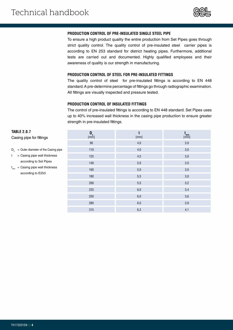
PRODUCTION CONTROL OF INSULATED FITTINGS The control of pre-insulated fittings is according to EN 448 standard. Set Pipes uses
up to 40% increased wall thickness in the casing pipe production to ensure greater
strength in pre-insulated fittings.
TABLE 2.0.7Casing pipe for fittings
Do = Outer diameter of the Casing pipe
t = Casing pipe wall thickness
according to Set Pipes
tmin = Casing pipe wall thickness
according to E253
Do [mm]
t[mm]
tmin[mm]
90 4,0 3,0
110 4,0 3,0
125 4,5 3,0
140 5,0 3,0
160 5,0 3,0
180 5,5 3,0
200 5,5 3,2
225 6,0 3,4
250 6,0 3,6
280 6,0 3,9
315 6,3 4,1

Technical handbook
TH170201EN /// 5
HEAT DEMANDTo define the pipe dimension of the district heating system the following must be
taken into consideration, heating, drinking water, snow melting and other uses.
The pipe diameter is determined by the sum of the previously mentioned usage.
In the case of heating, the following equation can be used:
THUS: = Mass flow [m3/s]
Q = Thermal requirement [W]
w = Water density (978 kg/m3 at 70°C)
cp = Specific heat for water (4191 J/kg·K at 70°C)
ΔT = Temperature change between flow and return pipelines (TVL - TRL) [K]
TOTAL PRESSURE LOSS FOR PRE - INSULATED STEEL PIPES After the water demand has been determined it is possible to calculate the pressure
loss for a selected pipe dimension. Network length, height difference, the number
of connections, and branches have an influence on the pressure loss. The pressure
loss in pipes should be in the range of 100 – 200 Pa/m for DN < 150, and 100 – 150
Pa/m for DN ≥ 150. Pressure loss requirements can vary depending on the system,
for example a system with a high pressure can lead to increased operating costs.To
calculate the pressure loss for each pipe dimension the following equation can be
used:
CHAPTER 2.1APPLICATION RANGE
CHAPTER 2.1.1PRESSURE LOSS
EXAMPLE: A house has the thermal requirement of 14 kW and temperature change between flow and return pipelines is 40°C. If we estimate the specific heat and density for 70°C water then we can find the water demand for the house:
THUS: f = Friction factor [-]
L = Length of the pipe [m]
di = Inner diameter of the steel pipe [m]]
V = Average water velocity [m/s]
w = Water density (972 kg/m3 at 80°C)
Hm = Height difference [m]
g = Acceleration due to gravity
Pipe

Technical handbook
TH170201EN /// 6
The friction factor is found with the following equation:
THUS:k = Resistance Coefficients for steel = 0,10 mm
Re = Reynolds number for flow in a circular pipe
The friction factor can also be found roughly with the Moody chart which can be
seen in graph 2.1.1.1 However, to find this factor it is necessary to know what kind of
flow is in the pipeline. The type of flow is determined with the Reynolds number (Re)
equation:
THUS: = Kinematic viscosity for water: 0,366 x 10-6 m2/s at 80°C
Reynolds number < 2300 forms a laminar flow which is smooth, steady and
therefore low pressure loss in the pipe. If the Reynolds number is > 4000 then
the flow will be turbulent which is fluctuating and agitated vortex that leads to
increasing pressure loss in the pipe. Higher Reynolds number leads to stronger vortex,
therefore greater pressure drop and more danger of cavitation forming in the pipe
and fittings. Between 2300 – 4000 forms a transition to turbulence flow.
Graph 2.1.1.2 shows pressure loss in a single flow pipe taking into consideration
water need, pipe dimension, and average water velocity. Also there is an example
on how to use the graph.

Technical handbook
TH170201EN /// 7
103
104
105
106
107
108
10−2
10−1 89
1.2
1.4
1.6
1.82
2.53
3.54
4.55
5.56789
67
82
34
56
78
23
45
67
82
34
56
78
23
45
67
82
34
56
78
1e−0
05
2e−0
05
5e−0
05
0.00
01
0.00
02
0.00
04
0.00
06
0.00
080.
001
0.00
15
0.00
2
0.00
3
0.00
4
0.00
6
0.00
8
0.01
0.01
250.
015
0.01
750.
02
0.02
5
0.03
0.03
5
0.04
0.04
50.
05
0.06
0.07
Lam
inar
flow
Crit
ical
zone
Tra
nsiti
on z
one
Com
plet
e tu
rbul
ence
, rou
gh p
ipes
, R >
350
0/r,
1/√
f =
1.14
− 2
log
r
Darcy−Weisbach friction factor f
Mo
od
y D
iag
ram
Mat
eria
l
Riv
eted
ste
elC
oncr
ete
Woo
d st
ave
Cas
t iro
nG
alva
nize
d iro
nA
spha
lted
cast
iron
Com
mer
cial
ste
elD
raw
n tu
bing
Rey
nold
s nu
mbe
rR
(V
in m
/s, D
in m
, ν in
m 2/s
)V
D ν
Relative roughness r (ε in mm, D in mm)εD
VD
for w
ater
at 2
0°C
(V
in m
/s, D
in c
m)
0.06 |
|0.
1 |0.
2 |0.
4 |0.
6 |0.
8 |1 |
2 |4 |
6 |8 |
10 |20 |
40 |60 |
|10
0 |20
0 |40
0 |60
0 ||
1000 |
2000 |
4000 |
6000 |
|10
000
|__
____
____
____
____
____
____
____
____
____
____
____
____
____
____
____
____
____
____
____
____
____
____
____
____
____
____
____
____
____
____
____
____
____
____
____
____
____
____
____
____
____
____
____
____
____
____
____
____
__
VD
for a
tmos
pher
ic a
ir at
20°
C1 |
2 |4 |
6 |8 |
10 |20 |
40 |60 |
|10
0 |20
0 |40
0 |60
0 ||
1000 |
2000 |
4000 |
6000 |
|10
000
|20
000
|40
000
|60
000
||10
0000
|
ε (m
m)
0.9−
90.
3−3
0.18
−0.9
0.25
0.15
0.12
0.04
60.
0015
Flui
d at
20°
C
Wat
erAi
r (10
1.32
5 kP
a)
ν (m
2 /s)
1.00
3e−0
061.
511e
−005
GRAPH 2.1.1.1 MOODY CHART

Technical handbook
TH170201EN /// 8
AN EXAMPLE HOW TO USE THE PRESSURE LOSS GRAPHA residential area has a water demand of about 150 l/s. To determine what pipe dimension is suitable, the general rule
for a suitable pressure loss in water pipes is between 100 – 150 Pa/m. In this example it is determined that 100 Pa/m
results in an average water speed in the pipeline of about 2,0 m/s and the recommended pipe dimension would be
DN 300, inner diameter 312,7 mm.

Technical handbook
TH170201EN /// 9
GRAPH 2.1.1.2 - PRESSURE LOSS GRAPH FOR STEEL PIPE
DN2021,7 mm
DN2528,5 mm
DN3237,2 mm
DN4043,1 mm
DN5054,5 mm
DN6570,3 mm
DN8082,5 mm
DN100107,1 mm
DN125132,5 mm
DN150160,3 mm
DN200210,1 mm
DN250263,0 mm
DN300312,7 mm
DN350344,4 mm
DN400393,8 mm
DN450444,4 mm
DN500495,4 mm
DN600595,8 mm
DN700695,0 mm
DN800795,4 mm
0,0
0,1
1,0
10,0
100,0
1.000,0
10.000,0
10 100 1.000
[l/s]
[Pa/m]

Technical handbook
TH170201EN /// 10
TABLE 2.1.2.1Steel pipe free expansion [mm]
L = Total steel pipe length
ΔT = Temperature difference
L[m]
ΔT
40 K 50 K 60 K 70 K 80 K 90 K 100 K
10 5,0 6,3 7,6 8,8 10,1 11,3 12,6
20 10,1 12,6 15,1 17,6 20,2 22,7 25,2
30 15,1 18,9 22,7 26,5 30,2 34,0 37,8
40 20,2 25,2 30,2 35,3 40,3 45,4 50,4
50 25,2 31,5 37,8 44,1 50,4 56,7 63,0
60 30,2 37,8 45,4 52,9 60,5 68,0 75,6
70 35,3 44,1 52,9 61,7 70,6 79,4 88,2
80 40,3 50,4 60,5 70,6 80,6 90,7 100,8
90 45,4 56,7 68,0 79,4 90,7 102,1 113,4
100 50,4 63,0 75,6 88,2 100,8 113,4 126,0
110 55,4 69,3 83,2 97,0 110,9 124,7 138,6
120 60,5 75,6 90,7 105,8 121,0 136,1 151,2
CHAPTER 2.1.2EXPANSION
EXPANSION – PRE-INSULATED SINGLE STEEL PIPESThe pre-insulated material from Set Pipes is a rigid system consisting of medium
pipe, PUR-foam and a casing pipe, meaning a continuous connection between the
steel pipes, PUR-foam and casing pipe. All three components of the pipe expands
or shortens evenly depending on cold or warm water running through the pipe.
Forces working against expansion due to temperature changes Fa are soil weight force
and weight of pipe with water. Together these friction forces form the F force. These
calculations, as with other calculations in this book are based on EN 13941 standard.
FREE EXPANSIONSteel pipes have free expansion due to temperature difference without
consideration of friction forces and resistance. This change of length can be found with
the equation:
THUS:L = Total length of the steel pipe [mm]
= Expansion coefficient for steel = 12,6 x 10⁻⁶ K-1
ΔT = Temperature difference between Forward flow media and soil (TVL - TE) [K]
Table no. 2.1.2.1 shows calculations in regards to length of pipeline and temperature
difference.

Technical handbook
TH170201EN /// 11
FREE EXPANSION FORCEWhen the steel pipe expands due to heat, compressive force Fa forms in the steel
pipe. The free expansion force can be found with the equation:
THUS:ESt = Modulus of elasticity = 210 GPa
Ai = Steel pipe cross section [mm2]
Table no. 2.1.3.1 shows calculations in regards to cross sectioning of the steel pipe
and temperature difference. TABLE 2.1.3.1Free expansion force [kN]
DN = Diameter nominal
Ai = Steel pipe cross section
ΔT = Temperature difference
DNAi ΔT
[mm2] 40 K 50 K 60 K 70 K 80 K 90 K 100 K
20 198,5 21,0 26,3 31,5 36,8 42,0 47,3 52,5
25 254,0 26,9 33,6 40,3 47,1 53,8 60,5 67,2
32 325,1 34,4 43,0 51,6 60,2 68,8 77,4 86,0
40 373,3 39,5 49,4 59,3 69,1 79,0 88,9 98,8
50 522,9 55,3 69,2 83,0 96,9 110,7 124,5 138,4
65 666,9 70,6 88,2 105,9 123,5 141,2 158,8 176,5
80 861,6 91,2 114,0 136,8 159,6 182,4 205,2 228,0
100 1252,0 132,5 165,6 198,8 231,9 265,0 298,1 331,3
125 1539,3 162,9 203,6 244,4 285,1 325,8 366,6 407,3
150 2064,7 218,5 273,2 327,8 382,4 437,0 491,7 546,3
200 3033,8 321,1 401,4 481,7 561,9 642,2 722,5 802,8
250 4209,7 445,6 556,9 668,3 779,7 891,1 1002,5 1113,9
300 5599,8 592,7 740,9 889,0 1037,2 1185,4 1333,5 1481,7
350 6157,5 651,7 814,6 977,6 1140,5 1303,4 1466,4 1629,3
400 7918,8 838,1 1047,7 1257,2 1466,7 1676,3 1885,8 2095,3
450 8920,3 944,1 1180,2 1416,2 1652,2 1888,2 2124,3 2360,3
500 9929,7 1051,0 1313,7 1576,4 1839,2 2101,9 2364,7 2627,4
600 13447,9 1423,3 1779,2 2135,0 2490,8 2846,6 3202,5 3558,3
700 17668,3 1870,0 2337,5 2805,0 3272,5 3740,0 4207,5 4675,0
800 22232,9 2353,1 2941,4 3529,7 4118,0 4706,3 5294,5 5882,8
CHAPTER 2.1.3EXPANSION FORCE

Technical handbook
TH170201EN /// 12
DISTANCE BETWEEN EXPANSIONS FOR SINGLE STEEL PIPE Forces working against expansion are soil weight force and weight of pipe with water.
Together these friction forces form a force that can be calculated with the following
equation:
THUS:K0 = The quiescent pressure correction factor = 0,50
e = Specific soil weight = 19000 N/m3
μ = Friction coefficient between casing pipe and sand bed = 0,40
Do = Outer diameter of the Casing pipe [m]
Hcc = Center line of pipe up to upper edge terrain [m]
FG = Pipe weight force with water [N/m]
Admissible assembling length from NFP (Natural Fix-Point) to compensation spot is
found out with the equation:
THUS: Zul = Maximum admissible axial tension for steel = 190 MPa
Ai = Steel pipe cross section [mm2]
Length between expansions for single steel pipe is then found out with the equation:
FIG 2.1.4.1Maximum length
between expansion
CHAPTER 2.1.4DISTANCE BETWEEN EXPANSIONS

Technical handbook
TH170201EN /// 13
The following table shows results for the maximum length between expansions in
regards to dimension and depth of pipeline.
TABLE 2.1.4.1Maximum length between
expansions [m] series 1
DN = Diameter Nominal
do = Outer diameter of steel pipe
t1 = Wall thickness of steel pipe
Do = Outer diameter of Casing pipe
t2 = Wall thickness of casing pipe
Steel pipes Casing pipe Depth
DN do[mm]
t1[mm]
Do[mm]
t2[mm] 0,60 m 0,80 m 1,0 m 1,2 m
20 26,9 2,6 90 3,0 73,7 56,4 45,7 38,4
25 33,7 2,6 90 3,0 94,0 72,0 58,4 49,1
32 42,4 2,6 110 3,0 96,8 74,4 60,5 50,9
40 48,3 2,6 110 3,0 110,9 85,3 69,3 58,4
50 60,3 2,9 125 3,0 134,7 104,0 84,7 71,4
65 76,1 2,9 140 3,0 151,0 117,0 95,5 80,6
80 88,9 3,2 160 3,0 167,6 130,4 106,7 90,3
100 114,3 3,6 200 3,2 188,2 147,5 121,3 103,0
125 139,7 3,6 225 3,4 200,9 158,3 130,6 111,1
150 168,3 4,0 250 3,6 236,3 187,2 155,0 132,2
200 219,1 4,5 315 4,1 261,2 209,1 174,4 149,6
250 273 5,0 400 4,8 268,3 217,5 182,8 157,7
300 323,9 5,6 450 5,2 304,3 248,5 210,1 181,9
350 355,6 5,6 500 5,6 291,7 239,6 203,3 176,6
400 406,4 6,3 560 6,0 320,7 265,5 226,5 197,5
450 457 6,3 630 6,6 307,6 256,5 219,9 192,5
500 508 6,3 710 7,2 290,4 243,9 210,3 184,8
600 610 7,1 800 7,9 327,9 278,2 241,5 213,4
700 711 8,0 900 8,7 359,8 308,0 269,3 239,2
800 813 8,8 1000 9,4 384,2 331,7 291,7 260,4

Technical handbook
TH170201EN /// 14
TABLE 2.1.4.2Maximum length between
expansions [m] series 2
DN = Diameter Nominal
do = Outer diameter of steel pipe
t1 = Wall thickness of steel pipe
Do = Outer diameter of casing pipe
t2 = Wall thickness of casing pipe
Steel pipes Casing pipe Depth
DN do[mm]
t1[mm]
Do[mm]
t2[mm] 0,60 m 0,80 m 1,0 m 1,2 m
20 26,9 2,6 110 3,0 59,4 45,6 37,0 31,2
25 33,7 2,6 110 3,0 75,9 58,3 47,3 39,8
32 42,4 2,6 125 3,0 84,3 65,0 52,9 44,6
40 48,3 2,6 125 3,0 96,6 74,5 60,6 51,1
50 60,3 2,9 140 3,0 119,1 92,1 75,1 63,4
65 76,1 2,9 160 3,0 130,5 101,4 82,9 70,1
80 88,9 3,2 180 3,0 147,2 114,8 94,1 79,7
100 114,3 3,6 225 3,4 164,9 129,6 106,8 90,8
125 139,7 3,6 250 3,6 178,3 140,9 116,4 99,2
150 168,3 4,0 280 3,9 207,7 165,0 136,9 117,0
200 219,1 4,5 355 4,5 227,1 182,6 152,7 131,2
250 273,0 5,0 450 5,2 232,9 189,6 159,9 138,2
300 323,9 5,6 500 5,6 267,8 219,6 186,1 161,5
350 355,6 5,6 560 6,0 253,6 209,3 178,2 155,1
400 406,4 6,3 630 6,6 276,8 230,3 197,2 172,4
450 457,0 6,3 710 7,2 264,2 221,5 190,7 167,4
500 508,0 6,3 800 7,9 248,8 210,2 181,9 160,3
600 610,0 7,1 900 8,7 281,3 239,8 209,1 185,3
700 711,0 8,0 1000 9,4 313,4 269,5 236,4 210,6
800 813,0 8,8 1100 10,2 338,8 293,7 259,1 231,9

Technical handbook
TH170201EN /// 15
TABLE 2.1.4.3Maximum length between
expansions [m] series 3
DN = Diameter Nominal
do = Outer diameter of steel pipe
t1 = Wall thickness of steel pipe
Do = Outer diameter of casing pipe
t2 = Wall thickness of casing pipe
Steel pipes Casing pipe Depth
DN do[mm]
t1[mm]
Do[mm]
t2[mm] 0,60 m 0,80 m 1,0 m 1,2 m
20 26,9 2,6 125 3,0 51,7 39,8 32,4 27,3
25 33,7 2,6 125 3,0 66,1 50,9 41,4 34,9
32 42,4 2,6 140 3,0 74,5 57,6 46,9 39,6
40 48,3 2,6 140 3,0 85,4 66,0 53,8 45,4
50 60,3 2,9 160 3,0 102,9 79,8 65,2 55,1
65 76,1 2,9 180 3,0 114,5 89,2 73,1 61,9
80 88,9 3,2 200 3,2 130,8 102,3 84,0 71,3
100 114,3 3,6 250 3,6 146,2 115,3 95,2 81,1
125 139,7 3,6 280 3,9 156,4 124,1 102,8 87,7
150 168,3 4,0 315 4,1 181,1 144,5 120,2 102,9
200 219,1 4,5 400 4,8 196,9 159,0 133,4 114,9
250 273,0 5,0 500 5,6 204,5 167,2 141,5 122,6
300 323,9 5,6 560 6,0 232,6 191,7 163,0 141,8
350 355,6 5,6 630 6,6 218,4 181,3 154,9 135,2
400 406,4 6,3 710 7,2 237,4 198,6 170,7 149,7
450 457,0 6,3 800 7,9 226,0 190,6 164,7 145,1
500 508,0 6,3 900 8,7 212,6 180,6 157,0 138,9
600 610,0 7,1 1000 9,4 244,1 209,3 183,1 162,8
700 711,0 8,0 1100 10,2 275,5 238,0 209,5 187,1
800 813,0 8,8 1200 11,0 301,1 262,0 231,9 208,0

Technical handbook
TH170201EN /// 16
EXAMPLE: We know the temperature for the forward flow media is 80°C and for the return it is 60°C. We estimate the soil temperature to be 10°C. Thus we can calculate the average temperature of the water:
HEAT LOSS - PRE INSULATED STEEL PIPES One of the most important characteristics of district heating systems is their heat
retention. As most district heating stations in Europe have to burn gas, oil, biomass
or waste, good insulation and proper ground work is necessary. Set Pipes works
continously to improve foam insulation in close cooperation with its suppliers to help
improve energy efficiency and reduce CO2 emission.
All results in the following tables are calculated according to EN 13941.
To calculate the total heat loss per meter of buried pipe it is necessary to know the
average water temperature and the overall heat loss coefficient for the pipe line system.
The average temperature for the water is calculated with the following equation:
THUS:TVL = Forward flow media temperature [°C]
TRL = Return flow media temperature [°C]
TE = Soil temperature [°C]
Pre-insulated steel pipes are made up of three components, steel pipe, PUR
insulation foam and casing pipe. All of these materials have variable heat loss (q).
The following equation is used to calculate the thermal resisteance (R) for each
material which is then used to calculate overall heat loss coefficient (Upipe in ground).
CHAPTER 2.1.5HEAT LOSS
The calculation shows an average temperature of TM 60 K.

Technical handbook
TH170201EN /// 17
THERMAL RESISTANCE OF STEEL PIPE
THUS: St = Coefficient of thermal conductivity for steel pipe = 50,0 W/m·K
do = Steel pipe outer diameter [m]
di = Inner diameter of steel pipe [m]
THERMAL RESISTANCE OF THE INSULATION MATERIAL
THUS: PUR = Coefficient of thermal conductivity for PUR insulation = 0,0260 W/m·K
DPUR = Outer diameter of insulation material [m]
di = Outer diameter of steel pipe [m]
THERMAL RESISTANCE OF THE CASING PIPE
THUS: PE100 = Coefficient of thermal conductivity for the casing pipe = 0,400 W/m·K
Do = Outer diameter of casing pipe [m]
Di = Inner diameter of casing pipe [m]
THERMAL RESISTANCE OF THE SOILThe soil around the pipe line and its depth can also affect heat loss in the pipeline
system. With the following equation the thermal resistance of the soil is found out:
THUS: s = Coefficient of thermal conductivity for soil = 1,20 W/m·K
Do = Outer diameter of casing pipe [m
Zc = Is a corrected value of depth z, so that the surface transition insolence
Ro at the soil surface is included:

Technical handbook
TH170201EN /// 18
Another factor which affects the heat loss of the pipe system is when the flow and
return pipe are laid in the same trench with little distance between them. With the
following equation the thermal resistance of the heat exchange between flow and
return pipe is found:
THUS: C = Distance between the center lines of the pipes [m]
All thermal resistance factors results can now be summed and used in the following
equation to calculate overall heat loss coefficient:
Total heat loss per meter for buried pre-insulated steel pipe, is calculated with
the equation:
THUS: Hcc = Distance from the surface to the middle of the pipe plus radius of the
outer diameter of the casing
R0 = Thermal resistance surface material = 0,0685 m2·K/W
Pipe in ground
Pipe in ground

Technical handbook
TH170201EN /// 19
TOTAL HEAT LOSS FOR BURIED PRE- INSULATED STEEL PIPESIn tables 2.1.5.1, 2.1.5.2 og 2.1.5.3 the results for total heat loss for buried single pipe,
insulation series 1-3 in regards to overall heat loss coefficient and average water
temperature TM are shown.
TABLE 2.1.5.1 Heat loss for pre-insulated
steel pipe [W/m] insulation
series 1
DN = Diameter Nominal
Do = Outer diameter of casing pipe [m]
URör í jörð = Overall heat loss coefficient
TM = Average temperature [K]
DN Do[mm]
UPIPE IN
GROUND
[W/m·K]
TM
20 K 40 K 50 K 60 K 70 K 80 K
20 90 0,126 2,52 5,04 6,30 7,56 8,82 10,1
25 90 0,152 3,05 6,10 7,62 9,14 10,7 12,2
32 110 0,156 3,12 6,23 7,79 9,35 10,9 12,5
40 110 0,178 3,56 7,12 8,90 10,7 12,5 14,2
50 125 0,198 3,96 7,91 9,89 11,9 13,8 15,8
65 140 0,231 4,62 9,24 11,5 13,9 16,2 18,5
80 160 0,238 4,76 9,53 11,9 14,3 16,7 19,1
100 200 0,250 4,99 9,98 12,5 15,0 17,5 20,0
125 225 0,287 5,74 11,5 14,4 17,2 20,1 23,0
150 250 0,336 6,73 13,5 16,8 20,2 23,5 26,9
200 315 0,366 7,31 14,6 18,3 21,9 25,6 29,2
250 400 0,356 7,12 14,2 17,8 21,4 24,9 28,5
300 450 0,406 8,12 16,2 20,3 24,4 28,4 32,5
350 500 0,397 7,94 15,9 19,9 23,8 27,8 31,8
400 560 0,421 8,42 16,8 21,0 25,3 29,5 33,7
450 630 0,424 8,5 17,0 21,2 25,5 29,7 33,9
500 710 0,413 8,3 16,5 20,7 24,8 28,9 33,0
600 800 0,497 9,9 19,9 24,9 29,8 34,8 39,8
700 900 0,563 11,3 22,5 28,2 33,8 39,4 45,1
800 1000 0,63 12,6 25,3 31,6 37,9 44,2 50,5

Technical handbook
TH170201EN /// 20
TABLE 2.1.5.2 Heat loss for pre-insulated
steel pipe [W/m] insulation
series 2
DN = Diameter Nominal
Do = Outer diameter of casing pipe [m]
URör í jörð = Overall heat loss coefficient
TM = Average temperature [K]
DN Do[mm]
UPIPE IN
GROUND
[W/m·K]
TM
20 K 40 K 50 K 60 K 70 K 80 K
20 110 0,109 2,17 4,35 5,43 6,52 7,61 8,69
25 110 0,128 2,56 5,11 6,39 7,67 8,95 10,2
32 125 0,139 2,77 5,55 6,93 8,32 9,71 11,1
40 125 0,156 3,12 6,24 7,80 9,36 10,9 12,5
50 140 0,174 3,48 6,95 8,69 10,4 12,2 13,9
65 160 0,194 3,88 7,77 9,71 11,7 13,6 15,5
80 180 0,203 4,07 8,14 10,2 12,2 14,2 16,3
100 225 0,212 4,24 8,49 10,6 12,7 14,9 17,0
125 250 0,243 4,86 9,73 12,2 14,6 17,0 19,5
150 280 0,274 5,49 11,0 13,7 16,5 19,2 21,9
200 355 0,290 5,81 11,6 14,5 17,4 20,3 23,2
250 450 0,285 5,70 11,4 14,2 17,1 19,9 22,8
300 500 0,324 6,47 12,9 16,2 19,4 22,7 25,9
350 560 0,313 6,26 12,5 15,7 18,8 21,9 25,1
400 630 0,325 6,50 13,0 16,3 19,5 22,8 26,0
450 710 0,326 6,52 13,0 16,3 19,6 22,8 26,1
500 800 0,319 6,39 12,8 16,0 19,2 22,4 25,5
600 900 0,369 7,37 14,7 18,4 22,1 25,8 29,5
700 1000 0,416 8,3 16,6 20,8 25,0 29,1 33,3
800 1100 0,464 9,3 18,6 23,2 27,9 32,5 37,2
Technical handbook
TH170201EN /// 21
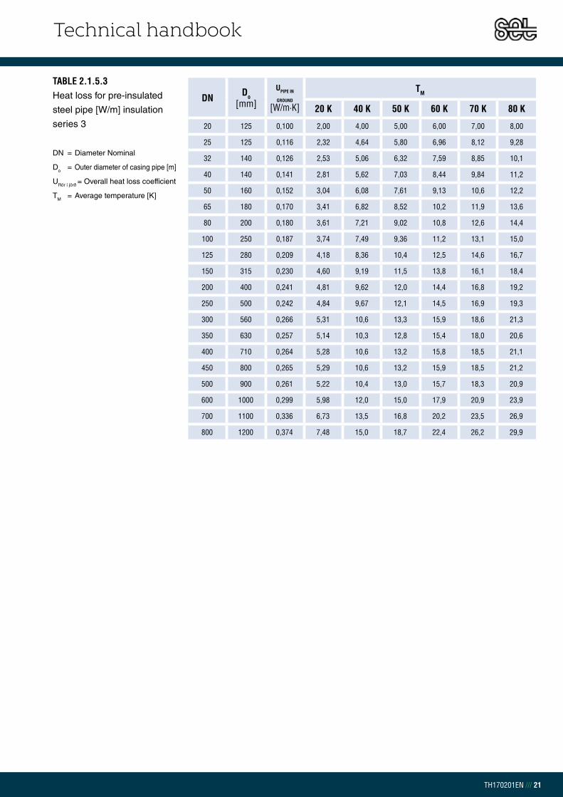
TABLE 2.1.5.3 Heat loss for pre-insulated
steel pipe [W/m] insulation
series 3
DN = Diameter Nominal
Do = Outer diameter of casing pipe [m]
URör í jörð = Overall heat loss coefficient
TM = Average temperature [K]
DN Do[mm]
UPIPE IN
GROUND
[W/m·K]
TM
20 K 40 K 50 K 60 K 70 K 80 K
20 125 0,100 2,00 4,00 5,00 6,00 7,00 8,00
25 125 0,116 2,32 4,64 5,80 6,96 8,12 9,28
32 140 0,126 2,53 5,06 6,32 7,59 8,85 10,1
40 140 0,141 2,81 5,62 7,03 8,44 9,84 11,2
50 160 0,152 3,04 6,08 7,61 9,13 10,6 12,2
65 180 0,170 3,41 6,82 8,52 10,2 11,9 13,6
80 200 0,180 3,61 7,21 9,02 10,8 12,6 14,4
100 250 0,187 3,74 7,49 9,36 11,2 13,1 15,0
125 280 0,209 4,18 8,36 10,4 12,5 14,6 16,7
150 315 0,230 4,60 9,19 11,5 13,8 16,1 18,4
200 400 0,241 4,81 9,62 12,0 14,4 16,8 19,2
250 500 0,242 4,84 9,67 12,1 14,5 16,9 19,3
300 560 0,266 5,31 10,6 13,3 15,9 18,6 21,3
350 630 0,257 5,14 10,3 12,8 15,4 18,0 20,6
400 710 0,264 5,28 10,6 13,2 15,8 18,5 21,1
450 800 0,265 5,29 10,6 13,2 15,9 18,5 21,2
500 900 0,261 5,22 10,4 13,0 15,7 18,3 20,9
600 1000 0,299 5,98 12,0 15,0 17,9 20,9 23,9
700 1100 0,336 6,73 13,5 16,8 20,2 23,5 26,9
800 1200 0,374 7,48 15,0 18,7 22,4 26,2 29,9
Technical handbook
TH170201EN /// 22
PRE-INSULATED SINGLE STEEL PIPES AND FITTINGSPre-insulated steel pipes and fittings are usually transported and delivered by truck.
Make sure that the truck has good access to the destination with 12 m lengths or
16 m if applicable. Pipes and fittings are sealed with protective plastic end caps
on the steel and must remain in place until assembly. All joint material as well as
accessories are delivered in plastic packaging. Do not remove packaging before
installation. The customer is responsible for the unloading of goods. Preparation
of a flat and a dry unloading area is required for safe unloading, making sure
nothing can damage the casing pipe. Pre-insulated steel pipes from Set Pipes are
delivered in bundles up to 280 casing according to the table below or loose according
to customer requests.
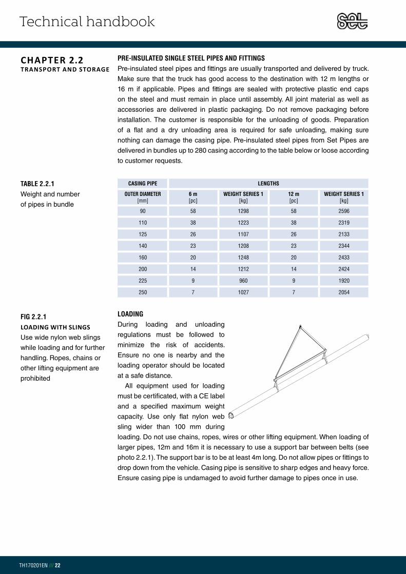
LOADINGDuring loading and unloading
regulations must be followed to
minimize the risk of accidents.
Ensure no one is nearby and the
loading operator should be located
at a safe distance.
All equipment used for loading
must be certificated, with a CE label
and a specified maximum weight
capacity. Use only flat nylon web
sling wider than 100 mm during
loading. Do not use chains, ropes, wires or other lifting equipment. When loading of
larger pipes, 12m and 16m it is necessary to use a support bar between belts (see
photo 2.2.1). The support bar is to be at least 4m long. Do not allow pipes or fittings to
drop down from the vehicle. Casing pipe is sensitive to sharp edges and heavy force.
Ensure casing pipe is undamaged to avoid further damage to pipes once in use.
CHAPTER 2.2TRANSPORT AND STORAGE
TABLE 2.2.1 Weight and number
of pipes in bundle
FIG 2.2.1 LOADING WITH SLINGS Use wide nylon web slings
while loading and for further
handling. Ropes, chains or
other lifting equipment are
prohibited
CASING PIPE LENGTHS
OUTER DIAMETER [mm]
6 m [pc]
WEIGHT SERIES 1 [kg]
12 m [pc]
WEIGHT SERIES 1 [kg]
90 58 1298 58 2596
110 38 1223 38 2319
125 26 1107 26 2133
140 23 1208 23 2344
160 20 1248 20 2433
200 14 1212 14 2424
225 9 960 9 1920
250 7 1027 7 2054

Technical handbook
TH170201EN /// 23
14 cm
Max 2,0m
Max 2,0m
STACK Pipes shall be stacked placing wooden strips with a minimum width of 140 mm
between pipes or laid on a stone free, flat and dry sand surface. Space between
wooden strips shall be no more than 2m. Stacking shall be done so the bottom layer
is supported and free from water and the maximum stacking height is 2 m. Ensure
the pressure does not exceed 0,3 N/mm2 (3 kg/cm2).
FIG 2.2.3BENDS AND T-PIECES Allow insulation surface
to lean downward
FITTINGS Fittings shall be stored so the insulation surface leans downward and is free from
any water.
If pipes or fittings are stored outside for longer periods of time ensure protection
against corrosion.
PUR INSULATION AND JOINT MATERIALStore shrink tubes, sleeves, expansion pads and other accessories where they are
protected from cold weather and direct sunlight. Liquid insulation components in
barrels, bottles or bags must be stored in a secured area at a temperature
between +10 and +20°C. Insulation material Poly (light coloured) and Isocyanate (dark
coloured) may under no circumstances freeze or reach a temperature below 0°C
during use or storage. Otherwise the foam can crystallize and be no longer possible
to use.
FIG 2.2.2STACKS WITH WOODEN SPACING STRIPSStack pipes so the maximum.
pressure does not exceed
<0,3 N/mm2 or 3 kg/cm2

Technical handbook
TH170201EN /// 24
PIPE-LAYING The casing pipe and the insulation foam move axially with the expansion of the
steel pipe. All occurring external forces coming from the surroundings transfers to
the steel through the soil.
It is important to take these in account and follow correct procedures to avoid un-
necessary pressure to the casing pipe, insulation and steel which can lead to a pre-
mature breakdown of the district heating system.
Points that impact the system´s lifespan are how temperature change varies and
the pipe laying in regards to expansion. The greatest strain is undoubtedly when
water is set through a buried cold layed pipeline and is reaching the flow line tem-
perature.
Different installation methods are possible to use for movement occurring
due to temperature changes in the system. Below the most important are dis-
cussed. Each project must be separately considered and if other methods
than recommended are to be used, please contact our technical department.
PROJECT PLANNING OF PRE-INSULATED PIPE SYSTEMS During project planning, factors like safety and size need to be taken into account.
The standard EN 13941 suggests the following classification:
EXPANSION FACTORS The standard recommends that calculated are four parameters to find an effective
system. The parameters are:
1. Factors due to internal pressure.
2. Factors due to repetitive strain.
3. Factors that can lead to instability or deformation.
4. Deformation or settlements that may affect the piping system,
external systems or structures.
More detailed description can be found in the EN 13941 standard.
CHAPTER 2.3FIELD WORK
TABLE 2.3.1 Project planning Class A
- Small and medium diameter pipes with low axial stresses- Low risk of damage to external systems and surroundings- System with low risk of economic losses
Class B - High axial stresses, small and medium diameter pipes
Class C- Large diameters pipes and/or high pressures- Higher risk of damage to external systems and surroundings- Special or complex construction

Technical handbook
TH170201EN /// 25
GRAPH 2.3.1Definition of project
classes for steel
CHAPTER 2.3.1COLD LAYING WITHOUT EXPANSION
COLD LAYING, WITHOUT EXPANSION BENDS With this installation technique it is possible to lay the pipeline directly in the trench
and put it into operation. This technique may only be used if the forward flow media
temperature, the difference between soil temperature and forward flow media
temperature is < 85°C and is then classified in class A. In class B the axial stresses
are high and temperature is between 85° < T < 130°C. With this method all external
factors have to be considered. For example height changes in landscape and small
degree bends are not allowed due to risk of buckling. The stress that occurs at
operation start up can be found with the equation:
THUS: St = Tensile and compressive stress [N/mm2]
ESt = Modulus of elasticity for steel = 210 GPa
= Expansion coefficient for steel = 12,6 x 10⁻⁶ K-1
ΔT = Temperature difference between forward flow media and soil (TVL - TE)
Diagram 2.3.1 is explained in table 2.3.1.1.
*ÍST EN 13941+A1:2010; p. 21; Fig 3, published with permission from Staðlaráðs Íslands.

Technical handbook
TH170201EN /// 26
DNdO
[mm]t
[mm]TVL
[°C]ΔT[K]
[N/mm2] rm/t Flokkur
20 26,9 2,6 50 40 106 5,2 A
25 33,7 2,6 55 45 119 6,5 A
32 42,4 2,6 60 50 132 8,2 A
40 48,3 2,6 65 55 146 9,3 A
50 60,3 2,9 70 60 159 10,4 A
65 76,1 2,9 75 65 172 13,1 A
80 88,9 3,2 80 70 185 13,9 A
100 114,3 3,6 85 75 198 15,9 A
125 139,7 3,6 90 80 212 19,4 A
150 168,3 4,0 95 85 225 21,0 A-B
200 219,1 4,5 100 90 238 24,3 B
250 273,0 5,0 105 95 251 27,3 B
300 323,9 5,6 110 100 265 28,9 B-C
350 355,6 5,6 115 105 278 31,8 C
400 406,4 6,3 120 110 291 32,3 C
450 457,0 6,3 125 115 304 36,3 C
500 508,0 6,3 130 120 318 40,3 C
600 610,0 7,1 135 125 331 43,0 C
TAFLA 2.3.1.1 Definition of project classes
for steel according to
EN 13941
DN = Diameter Nominal
do = Outer diameter of steel pipe
t = Wall thickness of steel pipe
TVL = Forward flow media temperature
ΔT = Temperature difference
= Inner tension of the steel
rm/t = Diameter and wall
thickness ratio
EXAMPLE: A system with 1500m pipe in DN 500 without expansion bends. Forward flow media temperature is 130°C and the temperature during pipe laying is 10°C.
The table shows a DN 500 with rm/t = 40,3. This shows that class C doesn´t allow such high expansions or maximum ca 245 N/mm2. In this situation bends need to be added or the flow pipeline temperature must be lowered.
Technical handbook
TH170201EN /// 27
A
x x
A
A
x
x
d
D
NAME
DEBUR AND
EDGES
FINISH:
ANGULAR:
Q.A
MFG
APPV'D
CHK'D
Expansion loopWEIGHT:
A3
SHEET 1 OF 1SCALE:1:50
SIGNATURE DATE TITLE:
REVISIONBREAK SHARP
DWG NO.MATERIAL:
DO NOT SCALE DRAWINGUNLESS OTHERWISE SPECIFIED:DIMENSIONS ARE IN MILLIMETERS
SURFACE FINISH:
TOLERANCES:
LINEAR:
DRAWN
D d
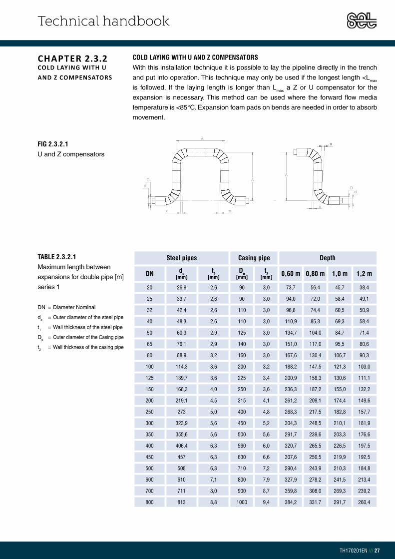
COLD LAYING WITH U AND Z COMPENSATORS With this installation technique it is possible to lay the pipeline directly in the trench
and put into operation. This technique may only be used if the longest length <Lmax
is followed. If the laying length is longer than Lmax a Z or U compensator for the
expansion is necessary. This method can be used where the forward flow media
temperature is <85°C. Expansion foam pads on bends are needed in order to absorb
movement.
FIG 2.3.2.1U and Z compensators
A
x x
A
A
x
x
d
D
NAME
DEBUR AND
EDGES
FINISH:
ANGULAR:
Q.A
MFG
APPV'D
CHK'D
Expansion loopWEIGHT:
A3
SHEET 1 OF 1SCALE:1:50
SIGNATURE DATE TITLE:
REVISIONBREAK SHARP
DWG NO.MATERIAL:
DO NOT SCALE DRAWINGUNLESS OTHERWISE SPECIFIED:DIMENSIONS ARE IN MILLIMETERS
SURFACE FINISH:
TOLERANCES:
LINEAR:
DRAWN
D d
CHAPTER 2.3.2COLD LAYING WITH U AND Z COMPENSATORS
TABLE 2.3.2.1Maximum length between
expansions for double pipe [m]
series 1
DN = Diameter Nominal
do = Outer diameter of the steel pipe
t1 = Wall thickness of the steel pipe
Do = Outer diameter of the Casing pipe
t2 = Wall thickness of the casing pipe
Steel pipes Casing pipe Depth
DN do[mm]
t1[mm]
Do[mm]
t2[mm] 0,60 m 0,80 m 1,0 m 1,2 m
20 26,9 2,6 90 3,0 73,7 56,4 45,7 38,4
25 33,7 2,6 90 3,0 94,0 72,0 58,4 49,1
32 42,4 2,6 110 3,0 96,8 74,4 60,5 50,9
40 48,3 2,6 110 3,0 110,9 85,3 69,3 58,4
50 60,3 2,9 125 3,0 134,7 104,0 84,7 71,4
65 76,1 2,9 140 3,0 151,0 117,0 95,5 80,6
80 88,9 3,2 160 3,0 167,6 130,4 106,7 90,3
100 114,3 3,6 200 3,2 188,2 147,5 121,3 103,0
125 139,7 3,6 225 3,4 200,9 158,3 130,6 111,1
150 168,3 4,0 250 3,6 236,3 187,2 155,0 132,2
200 219,1 4,5 315 4,1 261,2 209,1 174,4 149,6
250 273 5,0 400 4,8 268,3 217,5 182,8 157,7
300 323,9 5,6 450 5,2 304,3 248,5 210,1 181,9
350 355,6 5,6 500 5,6 291,7 239,6 203,3 176,6
400 406,4 6,3 560 6,0 320,7 265,5 226,5 197,5
450 457 6,3 630 6,6 307,6 256,5 219,9 192,5
500 508 6,3 710 7,2 290,4 243,9 210,3 184,8
600 610 7,1 800 7,9 327,9 278,2 241,5 213,4
700 711 8,0 900 8,7 359,8 308,0 269,3 239,2
800 813 8,8 1000 9,4 384,2 331,7 291,7 260,4

Technical handbook
TH170201EN /// 28
TAFLA 2.3.2.2Maximum length between
expansions for double pipe [m]
series 2
DN = Diameter Nominal
do = Outer diameter of the steel pipe
t1 = Wall thickness of the steel pipe
Do = Outer diameter of the Casing pipe
t2 = Wall thickness of the casing pipe
Steel pipes Casing pipe Depth
DN do[mm]
t1[mm]
Do[mm]
t2[mm] 0,60 m 0,80 m 1,0 m 1,2 m
20 26,9 2,6 110 3,0 59,4 45,6 37,0 31,2
25 33,7 2,6 110 3,0 75,9 58,3 47,3 39,8
32 42,4 2,6 125 3,0 84,3 65,0 52,9 44,6
40 48,3 2,6 125 3,0 96,6 74,5 60,6 51,1
50 60,3 2,9 140 3,0 119,1 92,1 75,1 63,4
65 76,1 2,9 160 3,0 130,5 101,4 82,9 70,1
80 88,9 3,2 180 3,0 147,2 114,8 94,1 79,7
100 114,3 3,6 225 3,4 164,9 129,6 106,8 90,8
125 139,7 3,6 250 3,6 178,3 140,9 116,4 99,2
150 168,3 4,0 280 3,9 207,7 165,0 136,9 117,0
200 219,1 4,5 355 4,5 227,1 182,6 152,7 131,2
250 273,0 5,0 450 5,2 232,9 189,6 159,9 138,2
300 323,9 5,6 500 5,6 267,8 219,6 186,1 161,5
350 355,6 5,6 560 6,0 253,6 209,3 178,2 155,1
400 406,4 6,3 630 6,6 276,8 230,3 197,2 172,4
450 457,0 6,3 710 7,2 264,2 221,5 190,7 167,4
500 508,0 6,3 800 7,9 248,8 210,2 181,9 160,3
600 610,0 7,1 900 8,7 281,3 239,8 209,1 185,3
700 711,0 8,0 1000 9,4 313,4 269,5 236,4 210,6
800 813,0 8,8 1100 10,2 338,8 293,7 259,1 231,9

Technical handbook
TH170201EN /// 29
EXPANSION FOAM PADSIn order to absorb expansion movements of the pipe system in bends, branches
or compensators, the right size of expansion pads must be used around the
casing pipe. Set Pipes expansion pads are manufactured from cross-linked closed-cell
polyethylene and have no water or chemical absorption. The pads are corrugated.
Once the pads are placed around the pipe a thin laminated wrap around is placed
over to protect from sand and soil.
The expansion foam pads are delivered in dimension 1000 x 2000 x 40 mm.
The foam pad thickness tells how much movement can be absorbed. Each pad is 40
mm thick and can absorb 35 mm, it is possible to put together up to three pads which
can absorb up to 105 mm.
Cutting size of expansion foam pad is according to table 2.3.3.1.
CHAPTER 2.3.3EXPANSION FOAM PADS
TAFLA 2.3.2.3Maximum length between
expansions for double pipe [m]
series 3
DN = Diameter Nominal
do = Outer diameter of the steel pipe
t1 = Wall thickness of the steel pipe
Do = Outer diameter of the Casing pipe
t2 = Wall thickness of the casing pipe
Steel pipes Casing pipe Depth
DN do[mm]
t1[mm]
Do[mm]
t2[mm] 0,60 m 0,80 m 1,0 m 1,2 m
20 26,9 2,6 125 3,0 51,7 39,8 32,4 27,3
25 33,7 2,6 125 3,0 66,1 50,9 41,4 34,9
32 42,4 2,6 140 3,0 74,5 57,6 46,9 39,6
40 48,3 2,6 140 3,0 85,4 66,0 53,8 45,4
50 60,3 2,9 160 3,0 102,9 79,8 65,2 55,1
65 76,1 2,9 180 3,0 114,5 89,2 73,1 61,9
80 88,9 3,2 200 3,2 130,8 102,3 84,0 71,3
100 114,3 3,6 250 3,6 146,2 115,3 95,2 81,1
125 139,7 3,6 280 3,9 156,4 124,1 102,8 87,7
150 168,3 4,0 315 4,1 181,1 144,5 120,2 102,9
200 219,1 4,5 400 4,8 196,9 159,0 133,4 114,9
250 273,0 5,0 500 5,6 204,5 167,2 141,5 122,6
300 323,9 5,6 560 6,0 232,6 191,7 163,0 141,8
350 355,6 5,6 630 6,6 218,4 181,3 154,9 135,2
400 406,4 6,3 710 7,2 237,4 198,6 170,7 149,7
450 457,0 6,3 800 7,9 226,0 190,6 164,7 145,1
500 508,0 6,3 900 8,7 212,6 180,6 157,0 138,9
600 610,0 7,1 1000 9,4 244,1 209,3 183,1 162,8
700 711,0 8,0 1100 10,2 275,5 238,0 209,5 187,1
800 813,0 8,8 1200 11,0 301,1 262,0 231,9 208,0

Technical handbook
TH170201EN /// 30
TABLE 2.3.3.1 Cutting size of expansion
foam pad
Do = Outer diameter of casing pipe [mm]
Y = Number of strips pcs.
b = Width [mm]
S = Size no.
Do[mm]
Ypc.
b[mm]
Snr.
90 2 120 1
110 2 120 1
125 2 120 1
140 2 120 1
160 2 120 1
180 4 240 2
200 4 240 2
225 4 240 2
250 4 240 2
280 4 240 2
315 6 360 3
355 6 360 3
400 8 480 4
450 8 480 4
500 8 480 4
560 10 600 5
630 12 720 6
710 14 840 7
FIG 2.3.3.1Installation of expansion
foam pads
Please contact Set Pipes technical department to determine the necessary width
of the foam pad needed.
TITLE:
A3
WEIGHT:
8 7
A
B
23456 1
578 246 13
E
D
C
F F
D
B
A
E
C
DRAWN
CHK'D
APPV'D
DWG NO.
SHEET 2 OF 2SCALE:1:10
REVISIONDO NOT SCALE DRAWING
MFG
Q.A
LINEAR:
ANGULAR:
FINISH:
TOLERANCES:
EDGES
NAME SIGNATURE DATE
MATERIAL:
UNLESS OTHERWISE SPECIFIED:
DIMENSIONS ARE IN MILLIMETERS
SURFACE FINISH:
DEBURR AND
BREAK SHARP
Beygjur m Þennslup
SECTION A-ASCALE 1 : 5
Expansion pad
Foam
Laminate
PE casing pipe
Steel pipe

Technical handbook
TH170201EN /// 31
EXAMPLE: A DN 150 (Series 2) pipe line which is 130 m long between compensators. How many layers of expansion foam pad is needed to take the expansion of the pipe if the starting temperature is 10°and ends at 100°C? We estimate the depth from the surface down to the casing pipe to be 1,0 m.
Using the following equation:
We know a one expansion foam pad can take max 35 mm pipe expansion. In this example we need to find how many layers of foam pad are needed to take 75 mm expansion. With the following equation we would need:
The figure on the side shows the installation of the expansion foam pads on a pipe line system. For 130 m it would need foam pads on both bends.
To determine the thickness of the expansion foam pad needed it is necessary to
know how much extension ΔL is occurring by using the following equation:
THUS:ΔLzul = Extension of the steel pipe [m]
= Expansion coefficient for steel = 12,6 x 10⁻⁶ K-1
ΔT = Starting temperature – finishing temperature [°C]
L = Pipe length < LZul [m]
FN = Resistance force of the pipe (see table 2.3.4) [kN/m]
Ai = Steel pipe cross section [m2]
ESt = Modulus of elasticity for steel = 210 GPa
3 layers of foam pad

Technical handbook
TH170201EN /// 32
PRE HEATING It is possible to pre-heat the pipeline in an open trench to avoid U- and Z compensators.
This can be done by filling the pipe with water to the correct temperature. It is also possible
to achieve with induction or steam heating. For pre-heating the following points must be
considered:
- Careful supervision of pipeline temperature is required during preheating.
- The pipeline must move freely and ensure an axially expansion.
- keep a constant temperature during backfilling.
- In case of considerable height differences between pipeline ends gravity must
be taken into account.
- Specialized engineers or technician to supervise and approve all procedures
Diameter Nominal
SERIES 1 SERIES 2 SERIES 3
Depth 0,6m
Depth 1,0m
Depth 1,2m
Depth 0,6m
Depth 1,0m
Depth 1,2m
Depth 0,6m
Depth 1,0m
Depth 1,2m
DN Ai [mm2] [kN/m] [kN/m] [kN/m] [kN/m] [kN/m] [kN/m] [kN/m] [kN/m] [kN/m]
20 198,5 1,02 1,65 1,97 1,27 2,04 2,42 1,46 2,33 2,77
25 254,0 1,03 1,65 1,97 1,27 2,04 2,42 1,46 2,33 2,77
32 325,1 1,28 2,04 2,43 1,47 2,34 2,77 1,66 2,63 3,12
40 373,3 1,28 2,05 2,43 1,47 2,34 2,78 1,66 2,64 3,12
50 522,9 1,48 2,35 2,78 1,67 2,64 3,13 1,93 3,05 3,61
65 666,9 1,68 2,65 3,14 1,94 3,06 3,62 2,21 3,47 4,10
80 861,6 1,95 3,07 3,63 2,22 3,48 4,11 2,50 3,90 4,59
100 1252,0 2,53 3,92 4,62 2,89 4,45 5,24 3,25 5,00 5,87
125 1539,3 2,91 4,48 5,26 3,28 5,02 5,90 3,74 5,69 6,67
150 2064,7 3,32 5,06 5,93 3,78 5,73 6,71 4,33 6,53 7,63
200 3033,8 4,41 6,61 7,71 5,08 7,55 8,79 5,85 8,64 10,04
250 4209,7 5,96 8,75 10,14 6,87 10,01 11,58 7,82 11,31 13,05
300 5599,8 6,99 10,13 11,70 7,95 11,43 13,18 9,15 13,05 15,01
350 6157,5 8,02 11,51 13,25 9,23 13,13 15,08 10,71 15,11 17,30
400 7918,8 9,38 13,29 15,24 10,87 15,26 17,46 12,68 17,63 20,10
450 8920,3 11,02 15,41 17,61 12,83 17,78 20,25 15,00 20,58 23,37
500 9929,7 12,99 17,94 20,42 15,17 20,74 23,53 17,75 24,03 27,16
600 13447,9 15,58 21,16 23,95 18,17 24,44 27,58 20,93 27,91 31,39
700 17668,3 18,66 24,93 28,07 21,42 28,40 31,88 24,37 32,04 35,88
800 22232,9 21,99 28,96 32,45 24,93 32,60 36,44 28,06 36,43 40,61
TABLE 2.3.3.2Friction force [kN/m]
CHAPTER 2.3.4PRE HEATING

Technical handbook
TH170201EN /// 33
and for compressive stress
EXAMPLE: 2.100m DN 250 is to be used with a maximum temperature of 125°C and soil temperature of 10°C. The length changes of the pipeline during pre-heating as well as the tensile and compressive stress of the material has to be calculated.
Degree of 57,5 K causes stress and length change. The total length of the 2.100 m will be 1,5 m on each end of the pipeline. The steel stress is ±152 N/mm2.
When a pipeline is preheated the heating temperature must be determined.
Generally the average soil temperature (TE) and the maximum forward flow media
temperature (TVL) is used. The advantage of this method is that when the pipeline
is heated up to an average temperature it leads to only half the tensile and
compressive stress compared to cold laying. Do not exceed the permissible tensile
and compressive stress. To determine the temperature difference and ± strain the
following equations are used:
THUS:ΔT = Temperature difference [K]
TVL = Forward flow media temperature [°C]
TE = Soil temperature [°C]
THUS:
St = Tensile and compressive stress [N/mm2]
ESt = Modulus of elasticity for steel = 210 GPa
= Expansion coefficient for steel = 12,6 x 10⁻⁶ K-1

Technical handbook
TH170201EN /// 34
COMPENSATORSFor higher temperatures it is harder to compensate movements with expansion pads.
Then it may be necessary to preheat the pipe before it is covered. This process
is not fault free, and it may not be possible to keep the pipe trench open for the
duration of the project. When pre-heating is not possible, continuous compensa-
tors or one-step compensators can be used instead for similar results as pre-heat-
ing with an open trench. The difference between the continuous compensator and
one-step compensator is that the one-step compensator is welded in its fixed
position when the preheating has expanded with the required elongation. The
continuous compensator is installed in the pipe and compensates movements
continuously, the use of axial expansion joints has become less common.
For further information about compensators please contact Set Pipes sales
department.
INSTALLATION OF BURIED SINGLE PIPESThese specifications are in accordance to the EN 13941 standard.
WEATHER CONDITIONSIf the temperature drops below freezing the casing pipe gets sensitive to heavy
impact. The plastic material becomes brittle and can break. Set Pipes recommends
if the temperature goes below 5°C to preheat the casing pipe with a soft flame to a
temperature of about 20 – 30°C before work with bending, sawing, drilling or welding
starts. After a cold night, even once temperature reach 5°C it is still necessary to use
the above heating method as steel preserves the nights cold.
Transport in freezing temperatures must be carried out with caution due to the pipe
sensitivity to heavy impact and avoid sharp edges or stones.
CHAPTER 2.3.5COMPENSATORS
CHAPTER 2.3.6CONDITIONS

Technical handbook
TH170201EN /// 35
TRENCH Figures 2.3.7.1 og 2.3.7.2 3 shows assembling of pipe and dimensions of the pipe
trench. The distance between the pipe and surface (H) should be between 0,60 – 1,2 m.
Under special installation circumstances, like for a shallower trench or when the
trench lays under a road, please contact Set Pipe´s technical department for further
information.
The following tables show the minimum trench width (B) and the minimum distance
between pipes needed (C) according to casing pipe diameter.
TABLE 2.3.7.1Minimum trench width with
vertical parallel pipes [mm]
Da = Casing pipe
FIG 2.3.7.1Trench cross section with
vertical parallel pipes [mm]
CHAPTER 2.3.7TRENCH
Da 90 110 125 140 160 180 200 225 250 280 315 355 400 450 500 560 630 710 800 900 1000 1100
C 200 200 200 200 200 200 200 250 250 250 250 250 350 350 350 350 350 350 350 350 350 350
B 290 310 325 340 360 380 400 425 450 500 515 555 600 650 700 760 830 910 1000 1100 1200 1300
Technical handbook
TH170201EN /// 36
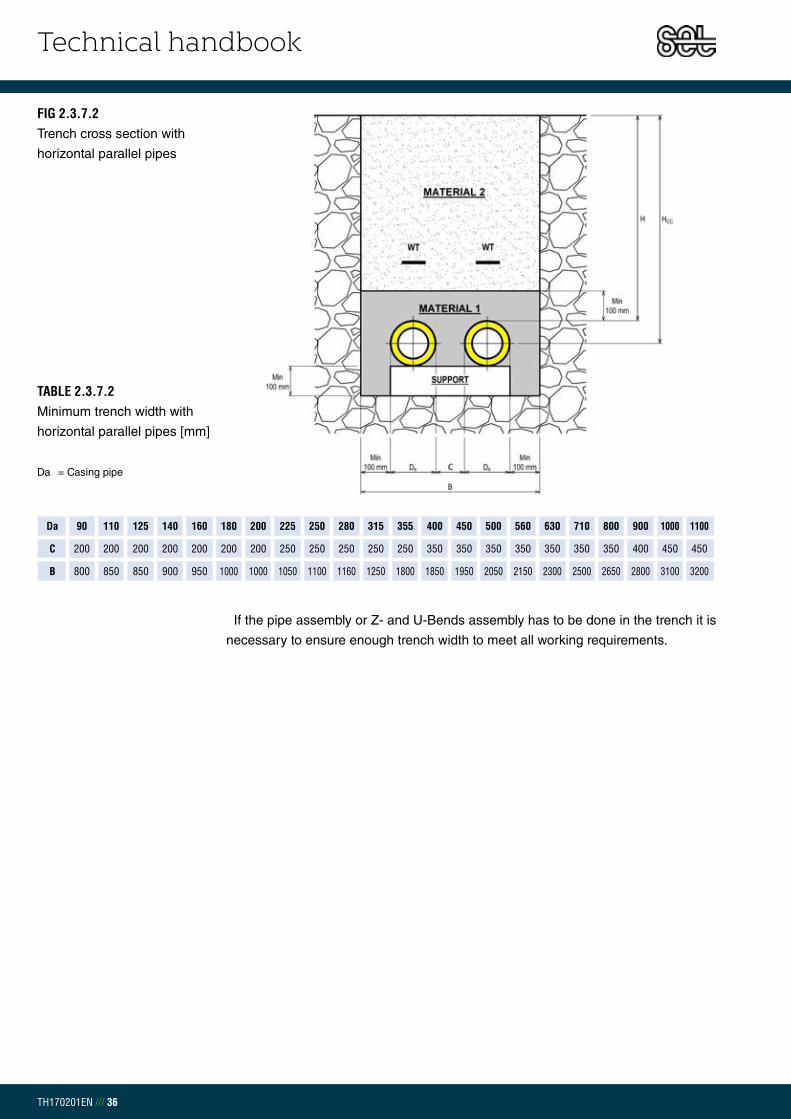
TABLE 2.3.7.2Minimum trench width with
horizontal parallel pipes [mm]
Da = Casing pipe
If the pipe assembly or Z- and U-Bends assembly has to be done in the trench it is
necessary to ensure enough trench width to meet all working requirements.
FIG 2.3.7.2Trench cross section with
horizontal parallel pipes
Da 90 110 125 140 160 180 200 225 250 280 315 355 400 450 500 560 630 710 800 900 1000 1100
C 200 200 200 200 200 200 200 250 250 250 250 250 350 350 350 350 350 350 350 400 450 450
B 800 850 850 900 950 1000 1000 1050 1100 1160 1250 1800 1850 1950 2050 2150 2300 2500 2650 2800 3100 3200

Technical handbook
TH170201EN /// 37
BACKFILLING 1 Before backfilling of the trench the following points must be reviewed:
- Pipe-laying guidelines are followed according to expansion design
- Verification of leak detection system
- Verification jointing is secure
- Stones and foreign objects which may have fallen from trench bank during
assembly are removed
- During preheating, expansion and temperature must be within predetermined
limits and documented.
To minimize heat loss from the ground surface use stone free fine sand that is free
from plant residues, humus, clay and silt lumps.
The sand must comply with following grain sizes to be classified as backfilling ma-
terial 1:
Begin trench filling with compacted sand ensuring the layer is at least 0,10 m after
compacting. The pipes are layed in the trench with the correct distance between (B)
and the minimum distance from the outer casing and trench side is 0,10 m.
It is necessary to compact the sand well around the pipes. Ensure the sand is
compacted similtaneously on both sides to avoid pipes moving out of place. The
backfill shall be made up in a way that neither its properties nor the compaction
causes damage to pipe and joints.
The sand layer above the district heating pipe should be minimum 0,10 m after
compaction.
MEDIUM GRAINED SAND 0-4 mm
FINE GRAINED SAND Max 8%
MAXIMUM GRAIN SIZE ≤ 32 mm
MAXIMUM GRAIN SIZE 10% OF WEIGHT ≤ 0,075 mm
MAXIMUM GRAIN SIZE 3% OF WEIGHT ≤ 0,020 mm
COEFFICIENT OF UNIFORMITY d60/d10 > 1,8
TABLE 2.3.8.1Backfilling material 1
description
CHAPTER 2.3.8BACKFILLING

Technical handbook
TH170201EN /// 38
BACKFILLING 2Before using backfilling material 2 place a warning type at a distance of approx. 0,20
– 0,50 m above the pipeline. Make sure that the backfilling material 2 doesn´t dam-
age the pipe or the fittings. In some cases the material from the trench can be reused,
but only if it contains a very small amount of organic material (e.g. humus and clay).
Remove bigger stones/rocks and other undesirable material. The backfilling should
follow in layers and compacted with necessary equipment which reaches 20 N/cm2.
The first backfilling layer must be fine-grained and the following layer can be coarse,
but each layer must always be at least 0,20 m after compaction.
ANCHOR INSTALLATIONTable 2.3.9.1 og figure 2.3.9.1 shows how concrete anchor blocks should be embed-
ded in a compacted, dry soil. Use KS 410 ribbed steel bars for the reinforcement.
Once cementing and other anchor work is complete follow instructions from backfill-
ing 1. It is important to finish compacting around the anchor before water is put into
the system. The compressive strength has to be 150 kN/m2 after compacting. Please
contact Set Pipe´s technical department if further information regarding anchoring
is needed.
STEEL DN
Hc[mm]
Dc[mm]
Bc[mm]
REBAR
NUMBER horizontal
NUMBER vertical
DIAMETER [mm]
25 500 800 1000 2 2 10
32 500 800 1200 2 2 10
40 500 800 1200 2 2 10
50 500 800 1200 2 2 10
65 800 800 1200 2 2 10
80 800 800 1300 2 2 10
100 800 800 2000 2 2 10
125 1100 800 2000 2 4 12
150 1100 800 2500 2 4 12
200 1400 800 3000 2 4 12
250 1400 1200 4000 4 4 14
300 1800 1200 4500 4 4 16
350 1800 1200 4500 4 4 20
400 2100 1500 5500 4 6 20
450 2100 1500 6000 4 6 20
500 2500 1800 6000 4 6 20
600 2500 2000 7000 6 8 20
700 2800 2500 8000 8 10 20
800 3000 2500 10000 10 12 20
TABLE 2.3.9.1Anchor dimensions
CHAPTER 2.3.9ANCHOR INSTALLATION

Technical handbook
TH170201EN /// 39
HOUSE CONNECTIONSHouse connections through the house concrete foundation or directly through
the wall. To ensure no expansion force enters the house, use fix points or bends
that can be installed outside the wall to compensate movements. The wall sealing
ring is available as a sealing for 0,5 – 5,0 Bar and must be chosen according to
circumstances. Set Pipes offers customized intake bends in different lengths if
required. Inside the house an endcap must be placed on the pipe end to protect the
foam. The pipe end closure (h) should be at least 100 mm from the floor/wall.
Vertical steel Horizontal steel
Q.A
WEIGHT:
A3
SHEET 1 OF 1
APPV'D
MFG
Festa í steypu EN
CHK'D
SCALE:1:50
DWG NO.
TITLE:
REVISIONDO NOT SCALE DRAWING
MATERIAL:
ANGULAR:
FINISH:
SIGNATURENAME
BREAK SHARP
DATE
EDGES
DEBUR AND UNLESS OTHERWISE SPECIFIED:
DIMENSIONS ARE IN MILLIMETERS
SURFACE FINISH:
TOLERANCES:
LINEAR:
DRAWN
FIG 2.3.9.1Anchor
FIG 2.3.10.1House connection
h
Sealing ring
Shrink end cap
CHAPTER 2.3.10HOUSE CONNECTIONS

Technical handbook
TH170201EN /// 40
STEEL WELDINGWelders for welding district heating pipes must carry a valid welding certificate
according to EN 287-1. Qualification of welding procedure specifications (WPS) must
be used during the steel welding process and Set Pipes recommends the use of
certified welding procedure (WPQR) during the welding of pre-insulated district
heating pipes. Set Pipes recommends gas welding for pipes < DN 80 and electric
welding for pipes > DN 80. Use welding electrodes of similar material as the welded
steel pipe. Under bad weather conditions place a tent over the welding area. Clean
rust and other dirt from pipe ends surface both inside and outside of the pipe. Rust
and dirt affect the welding quality.
It is recommended to weld joints on wooden plank supports above or beside the
trench. If welding is done after the pipes are in the trench ensure a wide and deep
enough trench. If necessary to shorten a pipe system Set Pipes recommends the pipes
rather than the fittings be shortened.
CHAPTER 2.3.11STEEL WELDING

Technical handbook
TH170201EN /// 41
CURVED PIPES Set Pipes supplies insulated curved pipes (R2,min). The pipes are available in
dimensions DN 20 – DN 500. Upon request, it is possible to bend DN 20 – DN 50
more than R2,min if required. It is possible to curve straight pipe on site after they have
been weldet together to the radius R1min.
THUS:R1,min = Minimum bending radius for pipeline on site [m]
R2,min = Minimum bending radius for one pipe [m]
y = Yield strength for steel = 235 MPa
ESt = Modulus of elasticity for steel = 210 Gpa
CHAPTER 2.3.12CURVED PIPES

Technical handbook
TH170201EN /// 42
FIG 2.3.12.1Curved pipe
STEELDN
DO[mm]
R1,MIN [m]
R2,MIN [m]
6 m pipes 12 m pipes
1[°] 2[°] 1[°] 2[°]
20 26,9 18,1 6,0 19,0 57,2 38,0 114,4
25 33,7 22,6 7,5 15,2 45,7 30,4 91,3
32 42,4 28,5 9,5 12,1 36,3 24,1 72,6
40 48,3 32,5 10,8 10,6 31,9 21,2 63,7
50 60,3 40,5 13,5 8,5 25,5 17,0 51,0
65 76,1 51,1 17,0 6,7 20,2 13,5 40,4
80 88,9 59,7 19,9 5,8 17,3 11,5 34,6
100 114,3 76,8 25,5 4,5 13,5 9,0 26,9
125 139,7 93,9 31,2 3,7 11,0 7,3 22,0
150 168,3 113,1 37,6 3,0 9,1 6,1 18,3
200 219,1 147,2 48,9 2,3 7,0 4,7 14,0
250 273,0 183,4 61,0 1,9 5,6 3,7 11,3
300 323,9 217,6 72,4 1,6 4,8 3,2 9,5
350 355,6 238,9 79,4 1,4 4,3 2,9 8,7
400 406,4 273,1 90,8 1,3 3,8 2,5 7,6
450 457,0 307,1 102,1 1,1 3,4 2,2 6,7
500 508,0 341,3 113,5 1,0 3,0 2,0 6,1
600 610,0 409,9 136,3 0,8 2,5 1,7 5,0
700 711,0 477,7 158,8 0,7 2,2 1,4 4,3
800 813,0 546,2 181,6 0,6 1,9 1,3 3,8
TABLE 2.3.12.1Pre-insulated steel pipes
do = Outer diameter of the steel pipe
R1min = Minimum bending radius for
pipeline on site
R2min = Minimum bending radius for
one pipe
1 = Curve angle R1
2 = Curve angle R2

Technical handbook
TH170201EN /// 43
6 meters Art no.
Steel Pipe Casing pipe PUR[mm]
Weight[kg/pc]DN d [mm] t1[mm] D [mm] t2 [mm]
1.101.020 20 26,9 2,6 90 3,0 28,6 16,4
1.101.025 25 33,7 2,6 90 3,0 25,2 18,9
1.101.032 32 42,4 2,6 110 3,0 30,8 24,5
1.101.040 40 48,3 2,6 110 3,0 27,9 26,6
1.101.050 50 60,3 2,9 125 3,0 29,4 35,2
1.101.065 65 76,1 2,9 140 3,0 29,0 43,4
1.101.080 80 88,9 3,2 160 3,0 32,6 55,0
1.101.100 100 114,3 3,6 200 3,2 39,7 79,5
1.101.125 125 139,7 3,6 225 3,4 39,3 96,7
1.101.150 150 168,3 4,0 250 3,6 37,3 124,8
1.101.200 200 219,1 4,5 315 4,1 43,9 183,3
12 meters Art no.
Steel Pipe Casing pipe PUR[mm]
Weight[kg/pc]DN d [mm] t1[mm] D [mm] t2 [mm]
1.102.020 20 26,9 2,6 90 3,0 28,6 32,9
1.102.025 25 33,7 2,6 90 3,0 25,2 37,8
1.102.032 32 42,4 2,6 110 3,0 30,8 49,0
1.102.040 40 48,3 2,6 110 3,0 27,9 53,1
1.102.050 50 60,3 2,9 125 3,0 29,4 70,4
1.102.065 65 76,1 2,9 140 3,0 29,0 86,8
1.102.080 80 88,9 3,2 160 3,0 32,6 110,1
1.102.100 100 114,3 3,6 200 3,2 39,7 159,0
1.102.125 125 139,7 3,6 225 3,4 39,3 193,3
1.102.150 150 168,3 4,0 250 3,6 37,3 249,6
1.102.200 200 219,1 4,5 315 4,1 43,9 366,5
1.102.250 250 273,0 5,0 400 4,8 58,7 523,6
1.102.300 300 323,9 5,6 450 5,2 57,9 677,5
1.102.350 350 355,6 5,6 500 5,6 66,6 764,6
1.102.400 400 406,4 6,3 560 6,0 70,8 967,6
1.102.450 450 457,0 6,3 630 6,6 83,2 1118,0
1.102.500 500 508,0 6,3 710 7,2 97,4 1288,0
1.102.600 600 610,0 7,1 800 7,9 91,1 1675,4
1.102.700 700 711,0 8,0 900 8,7 90,2 2150,0
1.102.800 800 813,0 8,8 1000 9,4 88,8 2657,5
CHAPTER 2.9.1PRE-INSULATED STEEL PIPESINSULATION SERIES 1
16 meters Art no.
Steel Pipe Casing pipe PUR[mm]
Weight[kg/pc]DN d [mm] t1[mm] D [mm] t2 [mm]
1.103.100 100 114,3 3,6 200 3,2 39,7 212,1
1.103.125 125 139,7 3,6 225 3,4 39,3 257,8
1.103.150 150 168,3 4,0 250 3,6 37,3 332,7
1.103.200 200 219,1 4,5 315 4,1 43,9 488,7
1.103.250 250 273,0 5,0 400 4,8 58,7 698,2
1.103.300 300 323,9 5,6 450 5,2 57,9 903,3
1.103.350 350 355,6 5,6 500 5,6 66,6 1019,5
1.103.400 400 406,4 6,3 560 6,0 70,8 1290,2
1.103.450 450 457,0 6,3 630 6,6 83,2 1490,6
1.103.500 500 508,0 6,3 710 7,2 97,4 1717,3
1.103.600 600 610,0 7,1 800 7,9 91,1 2233,9
1.103.700 700 711,0 8,0 900 8,7 90,2 2866,7
1.103.800 800 813,0 8,8 1000 9,4 88,8 3543,3
L
dD
200200
L
dD
200200
L
dD
200200
CHAPTER 2.9 PRODUCT CATALOGUE

Technical handbook
TH170201EN /// 44
PRE-INSULATED STEEL PIPESINSULATION SERIES 2
6 meters Art no.
Steel Pipe Casing pipe PUR[mm]
Weight[kg/pc]DN d [mm] t1[mm] D [mm] t2 [mm]
1.201.020 20 26,9 2,6 110 3,0 38,6 18,9
1.201.025 25 33,7 2,6 110 3,0 35,2 21,4
1.201.032 32 42,4 2,6 125 3,0 38,3 26,6
1.201.040 40 48,3 2,6 125 3,0 35,4 28,6
1.201.050 50 60,3 2,9 140 3,0 36,9 37,4
1.201.065 65 76,1 2,9 160 3,0 39,0 46,7
1.201.080 80 88,9 3,2 180 3,0 42,6 58,6
1.201.100 100 114,3 3,6 225 3,4 52,0 85,6
1.201.125 125 139,7 3,6 250 3,6 51,6 103,4
1.201.150 150 168,3 4,0 280 3,9 52,0 133,9
1.201.200 200 219,1 4,5 355 4,5 63,5 198,4
12 meters Art no.
Steel Pipe Casing pipe PUR[mm]
Weight[kg/pc]DN d [mm] t1[mm] D [mm] t2 [mm]
1.202.020 20 26,9 2,6 110 3,0 38,6 37,9
1.202.025 25 33,7 2,6 110 3,0 35,2 42,8
1.202.032 32 42,4 2,6 125 3,0 38,3 53,1
1.202.040 40 48,3 2,6 125 3,0 35,4 57,3
1.202.050 50 60,3 2,9 140 3,0 36,9 74,9
1.202.065 65 76,1 2,9 160 3,0 39,0 93,3
1.202.080 80 88,9 3,2 180 3,0 42,6 117,2
1.202.100 100 114,3 3,6 225 3,4 52,0 171,1
1.202.125 125 139,7 3,6 250 3,6 51,6 206,7
1.202.150 150 168,3 4,0 280 3,9 52,0 267,8
1.202.200 200 219,1 4,5 355 4,5 63,5 396,7
1.202.250 250 273,0 5,0 450 5,2 83,3 569,4
1.202.300 300 323,9 5,6 500 5,6 82,5 728,3
1.202.350 350 355,6 5,6 560 6,0 96,2 830,9
1.202.400 400 406,4 6,3 630 6,6 105,2 1056,6
1.202.450 450 457,0 6,3 710 7,2 122,9 1230,0
1.202.500 500 508,0 6,3 800 7,9 142,1 1430,0
1.202.600 600 610,0 7,1 900 8,7 140,7 1853,0
1.202.700 700 711,0 7,1 1000 9,4 139,8 2344,7
1.202.800 800 813,0 7,1 1100 10,2 138,4 2875,4
16 meters Art no.
Steel Pipe Casing pipe PUR[mm]
Weight[kg/pc]DN d [mm] t1[mm] D [mm] t2 [mm]
1.203.100 100 114,3 3,6 225 3,4 52,0 228,2
1.203.125 125 139,7 3,6 250 3,6 51,6 275,6
1.203.150 150 168,3 4,0 280 3,9 52,0 357,1
1.203.200 200 219,1 4,5 355 4,5 63,5 528,9
1.203.250 250 273,0 5,0 450 5,2 83,3 759,2
1.203.300 300 323,9 5,6 500 5,6 82,5 971,1
1.203.350 350 355,6 5,6 560 6,0 96,2 1107,9
1.203.400 400 406,4 6,3 630 6,6 105,2 1408,7
1.203.450 450 457,0 6,3 710 7,2 122,9 1640,0
1.203.500 500 508,0 6,3 800 7,9 142,1 1906,7
1.203.600 600 610,0 7,1 900 8,7 140,7 2470,7
1.203.700 700 711,0 7,1 1000 9,4 139,8 3126,3
1.203.800 800 813,0 7,1 1100 10,2 138,4 3833,9
LdD
200200
L
dD
200200
L
dD
200200

Technical handbook
TH170201EN /// 45
PRE-INSULATED STEEL PIPESINSULATION SERIES 3
6 meters Art no.
Steel Pipe Casing pipe PUR[mm]
Weight[kg/pc]DN d [mm] t1[mm] D [mm] t2 [mm]
1.301.020 20 26,9 2,6 125 3,0 46,1 21,0
1.301.025 25 33,7 2,6 125 3,0 42,7 23,5
1.301.032 32 42,4 2,6 140 3,0 45,8 28,8
1.301.040 40 48,3 2,6 140 3,0 42,9 30,9
1.301.050 50 60,3 2,9 160 3,0 46,9 40,7
1.301.065 65 76,1 2,9 180 3,0 49,0 50,2
1.301.080 80 88,9 3,2 200 3,2 52,4 63,1
1.301.100 100 114,3 3,6 250 3,6 64,3 92,3
1.301.125 125 139,7 3,6 280 3,9 66,3 112,5
1.301.150 150 168,3 4,0 315 4,1 69,3 145,0
1.301.200 200 219,1 4,5 400 4,8 85,7 216,4
12 meters Art no.
Steel Pipe Casing pipe PUR[mm]
Weight[kg/pc]DN d [mm] t1[mm] D [mm] t2 [mm]
1.302.020 20 26,9 2,6 125 3,0 46,1 42,0
1.302.025 25 33,7 2,6 125 3,0 42,7 46,9
1.302.032 32 42,4 2,6 140 3,0 45,8 57,6
1.302.040 40 48,3 2,6 140 3,0 42,9 61,8
1.302.050 50 60,3 2,9 160 3,0 46,9 81,4
1.302.065 65 76,1 2,9 180 3,0 49,0 100,4
1.302.080 80 88,9 3,2 200 3,2 52,4 126,2
1.302.100 100 114,3 3,6 250 3,6 64,3 184,5
1.302.125 125 139,7 3,6 280 3,9 66,3 225,0
1.302.150 150 168,3 4,0 315 4,1 69,3 290,0
1.302.200 200 219,1 4,5 400 4,8 85,7 432,9
1.302.250 250 273,0 5,0 500 5,6 107,9 620,3
1.302.300 300 323,9 5,6 560 6,0 112,1 794,6
1.302.350 350 355,6 5,6 630 6,6 130,6 919,8
1.302.400 400 406,4 6,3 710 7,2 144,6 1168,6
1.302.450 450 457,0 6,3 800 7,9 167,6 1372,0
1.302.500 500 508,0 6,3 900 8,7 191,7 1607,6
1.302.600 600 610,0 7,1 1000 9,4 190,3 2047,7
1.302.700 700 711,0 8,0 1100 10,2 189,4 2562,6
1.302.800 800 813,0 8,8 1200 11,0 188,0 3113,6
16 meters Art no.
Steel Pipe Casing pipe PUR[mm]
Weight[kg/pc]DN d [mm] t1[mm] D [mm] t2 [mm]
1.303.100 100 114,3 3,6 250 3,6 64,3 184,5
1.303.125 125 139,7 3,6 280 3,9 66,3 225,0
1.303.150 150 168,3 4,0 315 4,1 69,3 290,0
1.303.200 200 219,1 4,5 400 4,8 85,7 432,9
1.303.250 250 273,0 5,0 500 5,6 107,9 620,3
1.303.300 300 323,9 5,6 560 6,0 112,1 794,6
1.303.350 350 355,6 5,6 630 6,6 130,6 919,8
1.303.400 400 406,4 6,3 710 7,2 144,6 1168,6
1.303.450 450 457,0 6,3 800 7,9 167,6 1372,0
1.303.500 500 508,0 6,3 900 8,7 191,7 1607,6
1.303.600 600 610,0 7,1 1000 9,4 190,3 2047,7
1.303.700 700 711,0 8,0 1100 10,2 189,4 2562,6
1.303.800 800 813,0 8,8 1200 11,0 188,0 3113,6
L
dD
200200
L
dD
200200
L
dD
200200
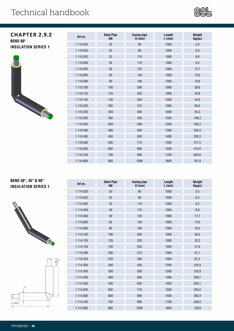
Technical handbook
TH170201EN /// 46
CHAPTER 2.9.2BEND 90°INSULATION SERIES 1
Art no. Steel Pipe DN
Casing pipe D [mm]
Length L [mm]
Weight[kg/pc]
1.110.020 20 90 1000 5,9
1.110.025 25 90 1000 6,8
1.110.032 32 110 1000 8,8
1.110.040 40 110 1000 9,6
1.110.050 50 125 1000 12,7
1.110.065 65 140 1000 15,6
1.110.080 80 160 1000 19,8
1.110.100 100 200 1000 28,6
1.110.125 125 225 1000 34,8
1.110.150 150 250 1000 44,9
1.110.200 200 315 1000 66,0
1.110.250 250 400 1000 94,3
1.110.300 300 450 1200 146,3
1.110.350 350 500 1200 165,2
1.110.400 400 560 1300 226,4
1.110.450 450 630 1400 259,3
1.110.500 500 710 1500 317,5
1.110.600 600 800 1500 414,0
1.110.700 700 900 1700 603,6
1.110.800 800 1000 1800 797,9
Art no. Steel Pipe DN
Casing pipe D [mm]
Length L [mm]
Weight[kg/pc]
1.114.020 20 90 1000 5,5
1.114.025 25 90 1000 6,3
1.114.032 32 110 1000 8,2
1.114.040 40 110 1000 8,9
1.114.050 50 125 1000 11,7
1.114.065 65 140 1000 14,5
1.114.080 80 160 1000 18,3
1.114.100 100 200 1000 26,5
1.114.125 125 225 1000 32,2
1.114.150 150 250 1000 41,6
1.114.200 200 315 1000 61,1
1.114.250 250 400 1000 87,3
1.114.300 300 450 1200 135,5
1.114.350 350 500 1200 152,9
1.114.400 400 560 1300 209,7
1.114.450 450 630 1400 240,1
1.114.500 500 710 1500 294,0
1.114.600 600 800 1500 383,4
1.114.700 700 900 1700 558,8
1.114.800 800 1000 1800 738,8
BEND 30°, 45° & 60°INSULATION SERIES 1

Technical handbook
TH170201EN /// 47
Art no. Steel Pipe DN
Casing pipe D [mm]
Length L [mm]
Weight[kg/pc]
1.111.020 20 90 500 3,0
1.111.025 25 90 500 3,4
1.111.032 32 110 500 4,4
1.111.040 40 110 500 4,8
1.111.050 50 125 500 6,3
1.111.065 65 140 500 7,8
1.111.080 80 160 500 9,9
1.111.100 100 200 500 14,3
BEND 90° SHORTINSULATION SERIES 1

Technical handbook
TH170201EN /// 48
BEND 90°INSULATION SERIES 2
Art no. Steel Pipe DN
Casing pipe D [mm]
Length L [mm]
Weight[kg/pc]
1.210.020 20 110 1000 6,8
1.210.025 25 110 1000 7,7
1.210.032 32 125 1000 9,6
1.210.040 40 125 1000 10,3
1.210.050 50 140 1000 13,5
1.210.065 65 160 1000 16,8
1.210.080 80 180 1000 21,1
1.210.100 100 225 1000 30,8
1.210.125 125 250 1000 37,2
1.210.150 150 280 1000 48,2
1.210.200 200 355 1000 71,4
1.210.250 250 450 1200 123,0
1.210.300 300 500 1200 157,3
1.210.350 350 560 1300 194,4
1.210.400 400 630 1400 266,3
1.210.450 450 710 1500 301,8
1.210.500 500 800 1500 347,8
1.210.600 600 900 1700 512,7
1.210.700 700 1000 1800 696,6
1.210.800 800 1100 2000 956,7
Art no. Steel Pipe DN
Casing pipe D [mm]
Length L [mm]
Weight[kg/pc]
1.214.020 20 110 1000 6,3
1.214.025 25 110 1000 7,1
1.214.032 32 125 1000 8,9
1.214.040 40 125 1000 9,5
1.214.050 50 140 1000 12,5
1.214.065 65 160 1000 15,6
1.214.080 80 180 1000 19,5
1.214.100 100 225 1000 28,5
1.214.125 125 250 1000 34,5
1.214.150 150 280 1000 44,6
1.214.200 200 355 1000 66,1
1.214.250 250 450 1200 113,9
1.214.300 300 500 1200 145,7
1.214.350 350 560 1300 180,0
1.214.400 400 630 1400 246,5
1.214.450 450 710 1500 279,5
1.214.500 500 800 1500 322,0
1.214.600 600 900 1700 474,7
1.214.700 700 1000 1800 645,0
1.214.800 800 1100 2000 885,8
BEND 30°, 45° & 60°INSULATION SERIES 2

Technical handbook
TH170201EN /// 49
Art no. Steel Pipe DN
Casing pipe D [mm]
Length L [mm]
Weight[kg/pc]
1.211.020 20 110 500 3,2
1.211.025 25 110 500 3,6
1.211.032 32 125 500 4,4
1.211.040 40 125 500 4,8
1.211.050 50 140 500 6,2
1.211.065 65 160 500 7,8
1.211.080 80 180 500 9,8
1.211.100 100 225 500 14,3
BEND 90° SHORTINSULATION SERIES 2
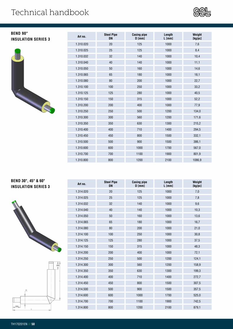
Technical handbook
TH170201EN /// 50
BEND 90°INSULATION SERIES 3
Art no. Steel Pipe DN
Casing pipe D [mm]
Length L [mm]
Weight[kg/pc]
1.310.020 20 125 1000 7,6
1.310.025 25 125 1000 8,4
1.310.032 32 140 1000 10,4
1.310.040 40 140 1000 11,1
1.310.050 50 160 1000 14,6
1.310.065 65 180 1000 18,1
1.310.080 80 200 1000 22,7
1.310.100 100 250 1000 33,2
1.310.125 125 280 1000 40,5
1.310.150 150 315 1000 52,2
1.310.200 200 400 1000 77,9
1.310.250 250 500 1200 134,0
1.310.300 300 560 1200 171,6
1.310.350 350 630 1300 215,2
1.310.400 400 710 1400 294,5
1.310.450 450 800 1500 332,1
1.310.500 500 900 1500 386,1
1.310.600 600 1000 1700 567,0
1.310.700 700 1100 1900 801,9
1.310.800 800 1200 2100 1086,9
Art no. Steel Pipe DN
Casing pipe D [mm]
Length L [mm]
Weight[kg/pc]
1.314.020 20 125 1000 7,0
1.314.025 25 125 1000 7,8
1.314.032 32 140 1000 9,6
1.314.040 40 140 1000 10,3
1.314.050 50 160 1000 13,6
1.314.065 65 180 1000 16,7
1.314.080 80 200 1000 21,0
1.314.100 100 250 1000 30,8
1.314.125 125 280 1000 37,5
1.314.150 150 315 1000 48,3
1.314.200 200 400 1000 72,1
1.314.250 250 500 1200 124,1
1.314.300 300 560 1200 158,9
1.314.350 350 630 1300 199,3
1.314.400 400 710 1400 272,7
1.314.450 450 800 1500 307,5
1.314.500 500 900 1500 357,5
1.314.600 600 1000 1700 525,0
1.314.700 700 1100 1900 742,5
1.314.800 800 1200 2100 879,1
BEND 30°, 45° & 60°INSULATION SERIES 3

Technical handbook
TH170201EN /// 51
Art no. Steel Pipe DN
Casing pipe D [mm]
Length L [mm]
Weight[kg/pc]
1.311.020 20 125 500 2,8
1.311.025 25 125 500 3,2
1.311.032 32 140 500 4,0
1.311.040 40 140 500 4,3
1.311.050 50 160 500 5,5
1.311.065 65 180 500 6,7
1.311.080 80 200 500 8,3
BEND 90° SHORTINSULATION SERIES 3

Technical handbook
TH170201EN /// 52
CHAPTER 2.9.3BRANCH 45°INSULATION SERIES 1
Art no.Main pipe Branch Length
L1/L2 [mm]
Weight[kg/pc]Steel pipe
DNCasing pipe
D1 [mm]Steel pipe
DNCasing pipe
D2 [mm]
1.124.020.020 20 90 20 90 1000/1000 4,7
1.124.025.020 25 90 20 90 1000/1000 5,1
1.124.025.025 25 90 25 90 1000/1000 5,6
1.124.032.020 32 110 20 90 1000/1000 5,8
1.124.032.025 32 110 25 90 1000/1000 6,3
1.124.032.032 32 110 32 110 1000/1000 7,2
1.124.040.020 40 110 20 90 1000/1000 6,3
1.124.040.025 40 110 25 90 1000/1000 6,7
1.124.040.032 40 110 32 110 1000/1000 7,6
1.124.040.040 40 110 40 110 1000/1000 7,9
1.124.050.020 50 125 20 90 1000/1000 7,7
1.124.050.025 50 125 25 90 1000/1000 8,1
1.124.050.032 50 125 32 110 1000/1000 9,0
1.124.050.040 50 125 40 110 1000/1000 9,3
1.124.050.050 50 125 50 125 1000/1000 10,9
1.124.065.020 65 140 20 90 1000/1000 9,0
1.124.065.025 65 140 25 90 1000/1000 9,4
1.124.065.032 65 140 32 110 1000/1000 10,3
1.124.065.040 65 140 40 110 1000/1000 10,6
1.124.065.050 65 140 50 125 1000/1000 12,2
1.124.065.065 65 140 65 140 1000/1000 13,6
1.124.080.020 80 160 20 90 1000/1000 10,6
1.124.080.025 80 160 25 90 1000/1000 11,2
1.124.080.032 80 160 32 110 1000/1000 12,0
1.124.080.040 80 160 40 110 1000/1000 12,4
1.124.080.050 80 160 50 125 1000/1000 13,9
1.124.080.065 80 160 65 140 1000/1000 15,3
1.124.080.080 80 160 80 160 1000/1000 17,3
1.124.100.025 100 200 25 90 1000/1000 14,9
1.124.100.032 100 200 32 110 1000/1000 15,7
1.124.100.040 100 200 40 110 1000/1000 16,1
1.124.100.050 100 200 50 125 1000/1000 17,6
1.124.100.065 100 200 65 140 1000/1000 19,0
1.124.100.080 100 200 80 160 1000/1000 21,0
1.124.100.100 100 200 100 200 1200/1000 27,8
1.124.125.025 125 225 25 90 1000/1000 17,5
1.124.125.032 125 225 32 110 1000/1000 18,4
1.124.125.040 125 225 40 110 1000/1000 18,8
1.124.125.050 125 225 50 125 1000/1000 20,3
1.124.125.065 125 225 65 140 1000/1000 21,7
1.124.125.080 125 225 80 160 1000/1000 23,6
1.124.125.100 125 225 100 200 1200/1000 31,0
1.124.125.125 125 225 125 225 1200/1000 33,9
1.124.150.025 150 250 25 90 1000/1000 22,1
1.124.150.032 150 250 32 110 1000/1000 22,9
1.124.150.040 150 250 40 110 1000/1000 23,3
1.124.150.050 150 250 50 125 1000/1000 24,8
1.124.150.065 150 250 65 140 1000/1000 26,2
5050
L2
D1
L1
200
200
200
D2
L2
D1
L1
200
200
200
D2

Technical handbook
TH170201EN /// 53
BRANCH 45°INSULATION SERIES 1 Art no.
Main pipe Branch Length L1/L2 [mm]
Weight[kg/pc]Steel pipe
DNCasing pipe
D1 [mm]Steel pipe
DNCasing pipe
D2 [mm]
1.124.150.080 150 250 80 160 1000/1000 28,1
1.124.150.100 150 250 100 200 1200/1000 36,4
1.124.150.125 150 250 125 225 1200/1000 39,3
1.124.150.150 150 250 150 250 1200/1000 44,1
1.124.200.025 200 315 25 90 1000/1000 31,3
1.124.200.032 200 315 32 110 1000/1000 32,1
1.124.200.040 200 315 40 110 1000/1000 32,5
1.124.200.050 200 315 50 125 1000/1000 34,0
1.124.200.065 200 315 65 140 1000/1000 35,3
1.124.200.080 200 315 80 160 1000/1000 37,2
1.124.200.100 200 315 100 200 1200/1000 47,5
1.124.200.125 200 315 125 225 1200/1000 50,4
1.124.200.150 200 315 150 250 1200/1000 55,3
1.124.200.200 200 315 200 315 1400/1000 71,8
1.124.250.025 250 400 25 90 1200/1000 52,4
1.124.250.032 250 400 32 110 1200/1000 53,2
1.124.250.040 250 400 40 110 1200/1000 53,5
1.124.250.050 250 400 50 125 1200/1000 54,8
1.124.250.065 250 400 65 140 1200/1000 56,0
1.124.250.080 250 400 80 160 1200/1000 57,7
1.124.250.100 250 400 100 200 1200/1000 62,6
1.124.250.125 250 400 125 225 1200/1000 65,4
1.124.250.150 250 400 150 250 1200/1000 70,2
1.124.250.200 250 400 200 315 1400/1000 89,5
1.124.250.250 250 400 250 315 1400/1000 103,6
1.124.300.025 300 450 25 90 1200/1000 67,8
1.124.300.032 300 450 32 110 1200/1000 68,5
1.124.300.040 300 450 40 110 1200/1000 68,9
1.124.300.050 300 450 50 125 1200/1000 70,4
1.124.300.065 300 450 65 140 1200/1000 71,8
1.124.300.080 300 450 80 160 1200/1000 73,6
1.124.300.100 300 450 100 200 1400/1200 92,1
1.124.300.125 300 450 125 225 1400/1200 95,5
1.124.300.150 300 450 150 250 1400/1200 101,2
1.124.300.200 300 450 200 315 1400/1200 113,3
1.124.300.250 300 450 250 400 1400/1200 130,1
1.124.300.300 300 450 300 450 1600/1200 158,9
1.124.350.025 350 500 25 90 1200/1000 76,5
1.124.350.032 350 500 32 110 1200/1000 76,8
1.124.350.040 350 500 40 110 1200/1000 77,2
1.124.350.050 350 500 50 125 1200/1000 78,7
1.124.350.065 350 500 65 140 1200/1000 80,0
1.124.350.080 350 500 80 160 1200/1000 81,9
1.124.350.100 350 500 100 200 1400/1200 102,0
1.124.350.125 350 500 125 225 1400/1200 105,4
1.124.350.150 350 500 150 250 1400/1200 111,1
1.124.350.200 350 500 200 315 1400/1200 123,1
5050
L2
D1
L1
200
200
200
D2
L2
D1
L1
200
200
200
D2

Technical handbook
TH170201EN /// 54
BRANCH 45°INSULATION SERIES 1 Art no.
Main pipe Branch Length L1/L2 [mm]
Weight[kg/pc]Steel pipe
DNCasing pipe
D1 [mm]Steel pipe
DNCasing pipe
D2 [mm]
1.124.350.250 350 500 250 400 1400/1200 139,9
1.124.350.300 350 500 300 450 1600/1300 168,2
1.124.350.350 350 500 350 500 1600/1300 179,7
1.124.400.040 400 560 40 110 1200/1000 97,4
1.124.400.050 400 560 50 125 1200/1000 98,8
1.124.400.065 400 560 65 140 1200/1000 100,2
1.124.400.080 400 560 80 160 1200/1000 102,0
1.124.400.100 400 560 100 200 1400/1200 125,7
1.124.400.125 400 560 125 225 1400/1200 129,1
1.124.400.150 400 560 150 250 1400/1200 134,7
1.124.400.200 400 560 200 315 1400/1200 146,7
1.124.400.250 400 560 250 400 1400/1200 163,3
1.124.400.300 400 560 300 450 1600/1300 194,0
1.124.400.350 400 560 350 500 1600/1300 203,7
1.124.400.400 400 560 400 560 1800/1300 254,2
1.124.450.050 450 630 40 110 1200/1000 104,3
1.124.450.065 450 630 50 125 1200/1000 105,8
1.124.450.080 450 630 65 140 1200/1000 107,0
1.124.450.100 450 630 80 160 1200/1000 108,8
1.124.450.125 450 630 100 200 1400/1200 133,4
1.124.450.150 450 630 125 225 1400/1200 136,8
1.124.450.200 450 630 150 250 1400/1200 142,3
1.124.450.250 450 630 200 315 1400/1200 154,1
1.124.450.300 450 630 250 400 1400/1200 170,4
1.124.450.350 450 630 300 450 1600/1300 210,2
1.124.450.400 450 630 350 500 1600/1300 249,0
1.124.450.450 450 630 450 560 1800/1300 269,6
1.124.500.040 500 710 40 110 1200/1000 118,4
1.124.500.050 500 710 50 125 1200/1000 119,8
1.124.500.065 500 710 65 140 1200/1000 121,0
1.124.500.080 500 710 80 160 1200/1000 122,8
1.124.500.100 500 710 100 200 1400/1200 150,1
1.124.500.125 500 710 125 225 1400/1200 153,4
1.124.500.150 500 710 150 250 1400/1200 158,9
1.124.500.200 500 710 200 315 1400/1200 170,6
1.124.500.250 500 710 250 400 1400/1200 186,8
1.124.500.300 500 710 300 450 1600/1300 218,7
1.124.500.350 500 710 350 500 1600/1300 227,9
1.124.500.400 500 710 400 560 1800/1300 284,1
1.124.500.450 500 710 450 630 1800/1300 291,0
1.124.500.500 500 710 500 710 1800/1300 308,7
1.124.600.065 600 800 65 140 1200/1200 159,3
1.124.600.080 600 800 80 160 1200/1200 161,4
1.124.600.100 600 800 100 200 1400/1200 193,3
1.124.600.125 600 800 125 225 1400/1200 196,6
1.124.600.150 600 800 150 250 1400/1200 201,9
1.124.600.200 600 800 200 315 1600/1400 247,0
5050
L2
D1
L1
200
200
200
D2
L2
D1
L1
200
200
200
D2
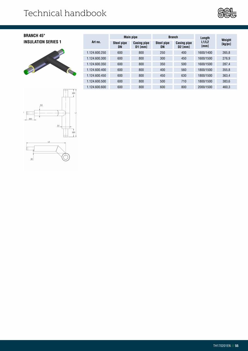
Technical handbook
TH170201EN /// 55
BRANCH 45°INSULATION SERIES 1 Art no.
Main pipe Branch Length L1/L2 [mm]
Weight[kg/pc]Steel pipe
DNCasing pipe
D1 [mm]Steel pipe
DNCasing pipe
D2 [mm]
1.124.600.250 600 800 250 400 1600/1400 265,8
1.124.600.300 600 800 300 450 1600/1500 276,9
1.124.600.350 600 800 350 500 1600/1500 287,4
1.124.600.400 600 800 400 560 1800/1500 355,8
1.124.600.450 600 800 450 630 1800/1500 363,4
1.124.600.500 600 800 500 710 1800/1500 383,6
1.124.600.600 600 800 600 800 2000/1500 460,3
5050
L2
D1
L1
200
200
200
D2
L2
D1
L1
200
200
200
D2

Technical handbook
TH170201EN /// 56
BRANCH 45°INSULATION SERIES 2 Art no.
Main pipe Branch Length L1/L2 [mm]
Weight[kg/pc]Steel pipe
DNCasing pipe
D1 [mm]Steel pipe
DNCasing pipe
D2 [mm]
1.224.020.020 20 110 20 110 1000/1000 5,3
1.224.025.020 25 110 20 110 1000/1000 5,7
1.224.025.025 25 110 25 110 1000/1000 6,1
1.224.032.020 32 125 20 110 1000/1000 6,4
1.224.032.025 32 125 25 110 1000/1000 7,0
1.224.032.032 32 125 32 125 1000/1000 7,9
1.224.040.020 40 125 20 110 1000/1000 6,4
1.224.040.025 40 125 25 110 1000/1000 7,3
1.224.040.032 40 125 32 125 1000/1000 8,3
1.224.040.040 40 125 40 125 1000/1000 8,6
1.224.050.020 50 140 20 110 1000/1000 8,3
1.224.050.025 50 140 25 110 1000/1000 8,7
1.224.050.032 50 140 32 125 1000/1000 9,6
1.224.050.040 50 140 40 125 1000/1000 10,0
1.224.050.050 50 140 50 140 1000/1000 11,5
1.224.065.020 65 160 20 110 1000/1000 9,7
1.224.065.025 65 160 25 110 1000/1000 10,1
1.224.065.032 65 160 32 125 1000/1000 11,0
1.224.065.040 65 160 40 125 1000/1000 11,4
1.224.065.050 65 160 50 140 1000/1000 12,9
1.224.065.065 65 160 65 160 1000/1000 14,4
1.224.080.020 80 180 20 110 1000/1000 11,4
1.224.080.025 80 180 25 110 1000/1000 12,0
1.224.080.032 80 180 32 125 1000/1000 12,9
1.224.080.040 80 180 40 125 1000/1000 13,3
1.224.080.050 80 180 50 140 1000/1000 14,8
1.224.080.065 80 180 65 160 1000/1000 16,3
1.224.080.080 80 180 80 180 1200/1000 19,8
1.224.100.025 100 225 25 110 1000/1000 15,9
1.224.100.032 100 225 32 125 1000/1000 16,8
1.224.100.040 100 225 40 125 1000/1000 17,2
1.224.100.050 100 225 50 140 1000/1000 18,7
1.224.100.065 100 225 65 160 1000/1000 20,2
1.224.100.080 100 225 80 180 1200/1000 23,9
1.224.100.100 100 225 100 225 1200/1000 29,7
1.224.125.025 125 250 25 110 1000/1000 18,7
1.224.125.032 125 250 32 125 1000/1000 19,6
1.224.125.040 125 250 40 125 1000/1000 20,0
1.224.125.050 125 250 50 140 1000/1000 21,5
1.224.125.065 125 250 65 160 1000/1000 23,0
1.224.125.080 125 250 80 180 1200/1000 27,2
1.224.125.100 125 250 100 225 1200/1000 33,0
1.224.125.125 125 250 125 225 1200/1000 36,2
1.224.150.025 150 280 25 110 1000/1000 23,5
1.224.150.032 150 280 32 125 1000/1000 24,4
1.224.150.040 150 280 40 125 1000/1000 24,8
1.224.150.050 150 280 50 140 1000/1000 26,3
5050
L2
D1
L1
200
200
200
D2
L2
D1
L1
200
200
200
D2
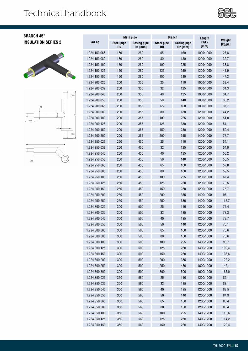
Technical handbook
TH170201EN /// 57
BRANCH 45°INSULATION SERIES 2 Art no.
Main pipe Branch Length L1/L2 [mm]
Weight[kg/pc]Steel pipe
DNCasing pipe
D1 [mm]Steel pipe
DNCasing pipe
D2 [mm]
1.224.150.065 150 280 65 160 1000/1000 27,8
1.224.150.080 150 280 80 180 1200/1000 32,7
1.224.150.100 150 280 100 225 1200/1000 38,8
1.224.150.125 150 280 125 250 1200/1000 41,9
1.224.150.150 150 280 150 280 1200/1000 47,2
1.224.200.025 200 355 25 110 1000/1000 33,4
1.224.200.032 200 355 32 125 1000/1000 34,3
1.224.200.040 200 355 40 125 1000/1000 34,7
1.224.200.050 200 355 50 140 1000/1000 36,2
1.224.200.065 200 355 65 160 1000/1000 37,7
1.224.200.080 200 355 80 180 1200/1000 44,2
1.224.200.100 200 355 100 225 1200/1000 51,0
1.224.200.125 200 355 125 630 1200/1000 54,1
1.224.200.150 200 355 150 280 1200/1000 59,4
1.224.200.200 200 355 200 355 1400/1000 77,7
1.224.250.025 250 450 25 110 1200/1000 54,1
1.224.250.032 250 450 32 125 1200/1000 54,9
1.224.250.040 250 450 40 125 1200/1000 55,2
1.224.250.050 250 450 50 140 1200/1000 56,5
1.224.250.065 250 450 65 160 1200/1000 57,8
1.224.250.080 250 450 80 180 1200/1000 59,5
1.224.250.100 250 450 100 225 1200/1000 67,4
1.224.250.125 250 450 125 250 1200/1000 70,5
1.224.250.150 250 450 150 280 1200/1000 75,7
1.224.250.200 250 450 200 355 1400/1000 97,1
1.224.250.250 250 450 250 630 1400/1000 112,7
1.224.300.025 300 500 25 110 1200/1000 72,4
1.224.300.032 300 500 32 125 1200/1000 73,3
1.224.300.040 300 500 40 125 1200/1000 73,7
1.224.300.050 300 500 50 140 1200/1000 75,1
1.224.300.065 300 500 65 160 1200/1000 76,6
1.224.300.080 300 500 80 180 1200/1000 78,6
1.224.300.100 300 500 100 225 1400/1200 98,7
1.224.300.125 300 500 125 250 1400/1200 102,4
1.224.300.150 300 500 150 280 1400/1200 108,6
1.224.300.200 300 500 200 355 1400/1200 122,2
1.224.300.250 300 500 250 450 1600/1200 142,1
1.224.300.300 300 500 300 500 1600/1200 165,0
1.224.350.025 350 560 25 110 1200/1000 82,1
1.224.350.032 350 560 32 125 1200/1000 83,1
1.224.350.040 350 560 40 125 1200/1000 83,5
1.224.350.050 350 560 50 140 1200/1000 84,9
1.224.350.065 350 560 65 160 1200/1000 86,4
1.224.350.080 350 560 80 180 1200/1000 88,4
1.224.350.100 350 560 100 225 1400/1200 110,6
1.224.350.125 350 560 125 250 1400/1200 114,2
1.224.350.150 350 560 150 280 1400/1200 120,4
5050
L2
D1
L1
200
200
200
D2
L2
D1
L1
200
200
200
D2

Technical handbook
TH170201EN /// 58
BRANCH 45°INSULATION SERIES 2 Art no.
Main pipe Branch Length L1/L2 [mm]
Weight[kg/pc]Steel pipe
DNCasing pipe
D1 [mm]Steel pipe
DNCasing pipe
D2 [mm]
1.224.350.200 350 560 200 355 1400/1200 133,9
1.224.350.250 350 560 250 450 1600/1200 154,1
1.224.350.300 350 560 300 500 1600/1300 175,3
1.224.350.350 350 560 350 560 1800/1300 218,9
1.224.400.040 400 630 40 125 1200/1000 105,2
1.224.400.050 400 630 50 140 1200/1000 106,6
1.224.400.065 400 630 65 160 1200/1000 108,1
1.224.400.080 400 630 80 180 1200/1000 110,1
1.224.400.100 400 630 100 225 1400/1200 136,3
1.224.400.125 400 630 125 250 1400/1200 139,9
1.224.400.150 400 630 150 280 1400/1200 146,1
1.224.400.200 400 630 200 355 1400/1200 159,5
1.224.400.250 400 630 250 450 1600/1200 181,2
1.224.400.300 400 630 300 500 1600/1300 202,0
1.224.400.350 400 630 350 560 1800/1300 252,3
1.224.400.400 400 630 400 630 1800/1300 279,1
1.224.450.050 450 710 40 125 1200/1000 112,2
1.224.450.065 450 710 50 140 1200/1000 113,5
1.224.450.080 450 710 65 160 1200/1000 115,0
1.224.450.100 450 710 80 180 1200/1000 116,9
1.224.450.125 450 710 100 225 1400/1200 144,0
1.224.450.150 450 710 125 250 1400/1200 147,6
1.224.450.200 450 710 150 280 1400/1200 153,6
1.224.450.250 450 710 200 355 1400/1200 166,9
1.224.450.300 450 710 250 450 1600/1200 188,4
1.224.450.350 450 710 300 500 1600/1300 208,7
1.224.450.400 450 710 350 560 1800/1300 261,0
1.224.450.450 450 710 400 630 1800/1300 287,4
1.224.450.450 450 710 450 710 1800/1300 294,6
1.224.500.040 500 800 40 125 1200/1000 130,0
1.224.500.050 500 800 50 140 1200/1000 131,4
1.224.500.065 500 800 65 160 1200/1000 132,8
1.224.500.080 500 800 80 180 1200/1000 134,7
1.224.500.100 500 800 100 225 1400/1200 165,5
1.224.500.125 500 800 125 250 1400/1200 169,0
1.224.500.150 500 800 150 280 1400/1200 175,0
1.224.500.200 500 800 200 355 1400/1200 188,2
1.224.500.250 500 800 250 450 1600/1200 210,9
1.224.500.300 500 800 300 500 1600/1300 230,8
1.224.500.350 500 800 350 560 1800/1300 289,5
1.224.500.400 500 800 400 630 1800/1300 315,7
1.224.500.450 500 800 450 710 1800/1300 322,9
1.224.500.500 500 800 500 800 1800/1300 346,3
1.224.600.065 600 900 65 160 1200/1200 170,7
1.224.600.080 600 900 80 180 1200/1200 173,0
1.224.600.100 600 900 100 225 1400/1200 208,1
1.224.600.125 600 900 125 250 1400/1200 211,6
5050
L2
D1
L1
200
200
200
D2
L2
D1
L1
200
200
200
D2

Technical handbook
TH170201EN /// 59
BRANCH 45°INSULATION SERIES 2 Art no.
Main pipe Branch Length L1/L2 [mm]
Weight[kg/pc]Steel pipe
DNCasing pipe
D1 [mm]Steel pipe
DNCasing pipe
D2 [mm]
1.224.600.125 600 900 125 250 1400/1200 211,6
1.224.600.150 600 900 150 280 1400/1200 217,5
1.224.600.200 600 900 200 355 1600/1400 267,4
1.224.600.250 600 900 250 450 1600/1400 288,5
1.224.600.300 600 900 300 500 1800/1500 344,2
1.224.600.350 600 900 350 560 1800/1500 358,7
1.224.600.400 600 900 400 630 1800/1500 388,6
1.224.600.450 600 900 450 710 1800/1500 396,5
1.224.600.500 600 900 500 800 1800/1500 423,2
1.224.600.600 600 900 600 900 2000/1500 503,0
5050
L2
D1
L1
200
200
200
D2
L2
D1
L1
200
200
200
D2

Technical handbook
TH170201EN /// 60
BRANCH 45°INSULATION SERIES 3 Art no.
Main pipe Branch Length L1/L2 [mm]
Weight[kg/pc]Steel pipe
DNCasing pipe
D1 [mm]Steel pipe
DNCasing pipe
D2 [mm]
1.324.020.020 20 125 20 125 1000/1000 6,0
1.324.025.020 25 125 20 125 1000/1000 6,4
1.324.025.025 25 125 25 125 1000/1000 6,8
1.324.032.020 32 140 20 125 1000/1000 7,1
1.324.032.025 32 140 25 125 1000/1000 7,6
1.324.032.032 32 140 32 140 1000/1000 8,5
1.324.040.020 40 140 20 125 1000/1000 7,6
1.324.040.025 40 140 25 125 1000/1000 8,0
1.324.040.032 40 140 32 140 1000/1000 8,9
1.324.040.040 40 140 40 140 1000/1000 9,3
1.324.050.020 50 160 20 125 1000/1000 9,0
1.324.050.025 50 160 25 125 1000/1000 9,5
1.324.050.032 50 160 32 140 1000/1000 10,4
1.324.050.040 50 160 40 140 1000/1000 10,7
1.324.050.050 50 160 50 160 1000/1000 12,4
1.324.065.020 65 180 20 125 1000/1000 10,5
1.324.065.025 65 180 25 125 1000/1000 10,9
1.324.065.032 65 180 32 140 1000/1000 11,8
1.324.065.040 65 180 40 140 1000/1000 12,2
1.324.065.050 65 180 50 160 1000/1000 13,8
1.324.065.065 65 180 65 180 1200/1000 16,1
1.324.080.020 80 200 20 125 1000/1000 12,2
1.324.080.025 80 200 25 125 1000/1000 12,8
1.324.080.032 80 200 32 140 1000/1000 13,7
1.324.080.040 80 200 40 140 1000/1000 14,0
1.324.080.050 80 200 50 160 1000/1000 15,7
1.324.080.065 80 200 65 180 1200/1000 17,9
1.324.080.080 80 200 80 200 1200/1000 20,2
1.324.100.025 100 250 25 125 1000/1000 17,1
1.324.100.032 100 250 32 140 1000/1000 17,9
1.324.100.040 100 250 40 140 1000/1000 18,4
1.324.100.050 100 250 50 160 1000/1000 20,0
1.324.100.065 100 250 65 180 1200/1000 22,7
1.324.100.080 100 250 80 200 1200/1000 24,6
1.324.100.100 100 250 100 250 1200/1000 31,9
1.324.125.025 125 280 25 125 1000/1000 20,2
1.324.125.032 125 280 32 140 1000/1000 21,0
1.324.125.040 125 280 40 140 1000/1000 21,4
1.324.125.050 125 280 50 160 1000/1000 23,1
1.324.125.065 125 280 65 180 1200/1000 26,2
1.324.125.080 125 280 80 200 1200/1000 28,0
1.324.125.100 125 280 100 250 1200/1000 35,7
1.324.125.125 125 280 125 280 1200/1000 39,2
1.324.150.025 150 315 25 125 1000/1000 25,3
1.324.150.032 150 315 32 140 1000/1000 26,1
1.324.150.040 150 315 40 140 1000/1000 26,5
1.324.150.050 150 315 50 160 1000/1000 28,2
5050
L2
D1
L1
200
200
200
D2
L2
D1
L1
200
200
200
D2

Technical handbook
TH170201EN /// 61
BRANCH 45°INSULATION SERIES 3 Art no.
Main pipe Branch Length L1/L2 [mm]
Weight[kg/pc]Steel pipe
DNCasing pipe
D1 [mm]Steel pipe
DNCasing pipe
D2 [mm]
1.324.150.065 150 315 65 180 1200/1000 31,8
1.324.150.080 150 315 80 200 1200/1000 33,7
1.324.150.100 150 315 100 250 1200/1000 41,9
1.324.150.125 150 315 125 280 1200/1000 45,4
1.324.150.150 150 315 150 315 1200/1000 51,2
1.324.200.025 200 400 25 125 1000/1000 36,2
1.324.200.032 200 400 32 140 1000/1000 37,0
1.324.200.040 200 400 40 140 1000/1000 37,4
1.324.200.050 200 400 50 160 1000/1000 39,0
1.324.200.065 200 400 65 180 1200/1000 37,0
1.324.200.080 200 400 80 200 1200/1000 45,7
1.324.200.100 200 400 100 250 1200/1000 55,3
1.324.200.125 200 400 125 280 1200/1000 58,8
1.324.200.150 200 400 150 315 1200/1000 64,6
1.324.200.200 200 400 200 400 1400/1000 85,0
1.324.250.025 250 500 25 125 1200/1000 56,1
1.324.250.032 250 500 32 140 1200/1000 56,9
1.324.250.040 250 500 40 140 1200/1000 57,2
1.324.250.050 250 500 50 160 1200/1000 58,5
1.324.250.065 250 500 65 180 1200/1000 59,8
1.324.250.080 250 500 80 200 1200/1000 61,6
1.324.250.100 250 500 100 250 1200/1000 72,9
1.324.250.125 250 500 125 280 1200/1000 76,4
1.324.250.150 250 500 150 315 1200/1000 82,1
1.324.250.200 250 500 200 400 1400/1000 106,0
1.324.250.250 250 500 250 500 1400/1000 123,0
1.324.300.025 300 560 25 125 1200/1000 78,6
1.324.300.032 300 560 32 140 1200/1000 79,4
1.324.300.040 300 560 40 140 1200/1000 79,8
1.324.300.050 300 560 50 160 1200/1000 81,4
1.324.300.065 300 560 65 180 1200/1000 83,1
1.324.300.080 300 560 80 200 1200/1000 85,0
1.324.300.100 300 560 100 250 1400/1200 107,5
1.324.300.125 300 560 125 280 1400/1200 111,7
1.324.300.150 300 560 150 315 1400/1200 118,5
1.324.300.200 300 560 200 400 1400/1200 133,8
1.324.300.250 300 560 250 500 1600/1200 148,7
1.324.300.300 300 560 300 560 1600/1000 183,6
1.324.350.025 350 630 25 125 1200/1000 90,4
1.324.350.032 350 630 32 140 1200/1000 90,9
1.324.350.040 350 630 40 140 1200/1000 91,3
1.324.350.050 350 630 50 160 1200/1000 92,8
1.324.350.065 350 630 65 180 1200/1000 94,5
1.324.350.080 350 630 80 200 1200/1000 96,4
1.324.350.100 350 630 100 250 1400/1200 121,3
1.324.350.125 350 630 125 280 1400/1200 125,5
1.324.350.150 350 630 150 315 1400/1200 132,3
5050
L2
D1
L1
200
200
200
D2
L2
D1
L1
200
200
200
D2

Technical handbook
TH170201EN /// 62
BRANCH 45°INSULATION SERIES 3 Art no.
Main pipe Branch Length L1/L2 [mm]
Weight[kg/pc]Steel pipe
DNCasing pipe
D1 [mm]Steel pipe
DNCasing pipe
D2 [mm]
1.324.350.200 350 630 200 400 1400/1200 147,6
1.324.350.250 350 630 250 500 1600/1200 161,5
1.324.350.300 350 630 300 560 1600/1300 184,2
1.324.350.350 350 630 350 630 1800/1300 243,3
1.324.400.040 400 710 40 140 1200/1000 116,8
1.324.400.050 400 710 50 160 1200/1000 118,4
1.324.400.065 400 710 65 180 1200/1000 120,0
1.324.400.080 400 710 80 200 1200/1000 122,0
1.324.400.100 400 710 100 250 1400/1200 151,8
1.324.400.125 400 710 125 280 1400/1200 156,0
1.324.400.150 400 710 150 315 1400/1200 162,7
1.324.400.200 400 710 200 400 1400/1200 177,9
1.324.400.250 400 710 250 500 1400/1200 198,2
1.324.400.300 400 710 300 560 1600/1300 215,1
1.324.400.350 400 710 350 630 1600/1300 226,8
1.324.400.400 400 710 400 710 1800/1300 316,1
1.324.450.050 450 800 50 160 1200/1000 123,8
1.324.450.065 450 800 65 180 1200/1000 125,3
1.324.450.080 450 800 80 200 1200/1000 126,9
1.324.450.100 450 800 100 250 1200/1000 128,8
1.324.450.125 450 800 125 280 1400/1200 159,5
1.324.450.150 450 800 150 315 1400/1200 163,7
1.324.450.200 450 800 200 400 1400/1200 170,3
1.324.450.250 450 800 250 500 1400/1200 185,3
1.324.450.300 450 800 300 560 1600/1200 221,8
1.324.450.350 450 800 350 630 1600/1300 233,3
1.324.450.400 450 800 400 710 1800/1300 292,2
1.324.450.450 450 800 450 800 1800/1300 324,4
1.324.500.040 500 900 40 140 1200/1000 141,1
1.324.500.050 500 900 50 160 1200/1000 142,7
1.324.500.065 500 900 65 180 1200/1000 144,2
1.324.500.080 500 900 80 200 1200/1000 146,2
1.324.500.100 500 900 100 250 1400/1200 180,4
1.324.500.125 500 900 125 280 1400/1200 184,5
1.324.500.150 500 900 150 315 1400/1200 191,2
1.324.500.200 500 900 200 400 1400/1200 206,1
1.324.500.250 500 900 250 500 1600/1200 219,0
1.324.500.300 500 900 300 560 1600/1300 240,5
1.324.500.350 500 900 350 630 1800/1300 320,0
1.324.500.400 500 900 400 710 1800/1300 352,0
1.324.500.450 500 900 450 800 1800/1300 359,5
1.324.500.500 500 900 500 900 1800/1300 382,7
1.324.600.065 600 1000 65 180 1200/1200 184,7
1.324.600.080 600 1000 80 200 1200/1200 187,0
1.324.600.100 600 1000 100 250 1400/1200 226,1
1.324.600.125 600 1000 125 280 1400/1200 230,1
5050
L2
D1
L1
200
200
200
D2
L2
D1
L1
200
200
200
D2
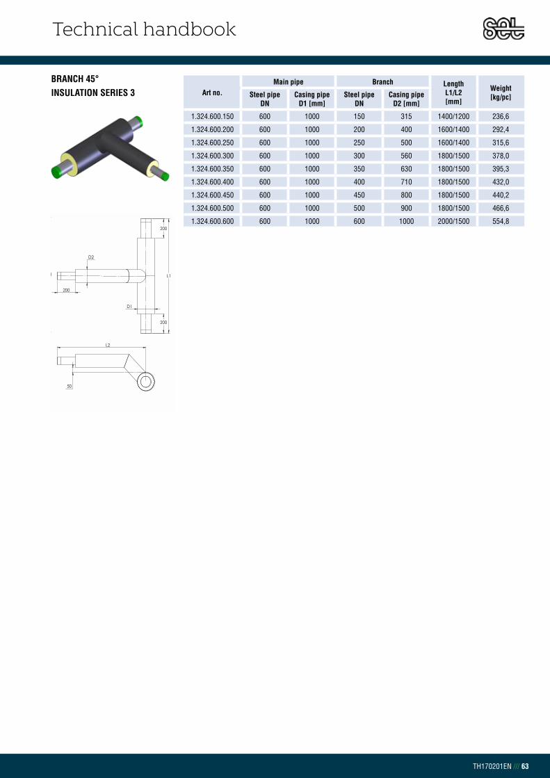
Technical handbook
TH170201EN /// 63
BRANCH 45°INSULATION SERIES 3 Art no.
Main pipe Branch Length L1/L2 [mm]
Weight[kg/pc]Steel pipe
DNCasing pipe
D1 [mm]Steel pipe
DNCasing pipe
D2 [mm]
1.324.600.150 600 1000 150 315 1400/1200 236,6
1.324.600.200 600 1000 200 400 1600/1400 292,4
1.324.600.250 600 1000 250 500 1600/1400 315,6
1.324.600.300 600 1000 300 560 1800/1500 378,0
1.324.600.350 600 1000 350 630 1800/1500 395,3
1.324.600.400 600 1000 400 710 1800/1500 432,0
1.324.600.450 600 1000 450 800 1800/1500 440,2
1.324.600.500 600 1000 500 900 1800/1500 466,6
1.324.600.600 600 1000 600 1000 2000/1500 554,8
5050
L2
D1
L1
200
200
200
D2
L2
D1
L1
200
200
200
D2

Technical handbook
TH170201EN /// 64
CHAPTER 2.9.4BRANCH PARALLELINSULATION SERIES 1
Art no. Main pipe Branch
Length L [mm]
C-C[mm]
Weight[kg/pc]Steel pipe
DNCasing pipe
D1 [mm]Steel pipe
DNCasing pipe
D2 [mm]
1.125.020.020 20 90 20 90 1000 240 3,9
1.125.025.020 25 90 20 90 1000 240 4,4
1.125.025.025 25 90 25 90 1000 240 4,6
1.125.032.020 32 110 20 90 1000 250 5,0
1.125.032.025 32 110 25 90 1000 250 5,4
1.125.032.032 32 110 32 110 1000 260 6,1
1.125.040.020 40 110 20 90 1000 250 5,5
1.125.040.025 40 110 25 90 1000 250 5,8
1.125.040.032 40 110 32 110 1000 260 6,4
1.125.040.040 40 110 40 110 1000 260 6,7
1.125.050.020 50 125 20 90 1000 258 6,9
1.125.050.025 50 125 25 90 1000 258 7,2
1.125.050.032 50 125 32 110 1000 268 7,8
1.125.050.040 50 125 40 110 1000 268 8,1
1.125.050.050 50 125 50 125 1000 275 9,2
1.125.065.020 65 140 20 90 1000 265 8,2
1.125.065.025 65 140 25 90 1000 265 8,5
1.125.065.032 65 140 32 110 1000 275 9,1
1.125.065.040 65 140 40 110 1000 275 9,4
1.125.065.065 65 140 50 125 1000 283 10,5
1.125.065.050 65 140 65 140 1000 290 11,6
1.125.080.020 80 160 20 90 1000 275 10,0
1.125.080.025 80 160 25 90 1000 275 10,3
1.125.080.032 80 160 32 110 1000 285 10,9
1.125.080.040 80 160 40 110 1000 285 11,2
1.125.080.050 80 160 50 125 1000 293 12,3
1.125.080.065 80 160 65 140 1000 300 13,4
1.125.080.080 80 160 80 160 1000 310 14,9
1.125.100.025 100 200 25 90 1000 295 14,0
1.125.100.032 100 200 32 110 1000 305 14,3
1.125.100.040 100 200 40 110 1000 305 15,0
1.125.100.050 100 200 50 125 1000 313 16,1
1.125.100.065 100 200 65 140 1000 320 17,2
1.125.100.080 100 200 80 160 1000 330 18,7
1.125.100.100 100 200 100 200 1200 350 26,0
1.125.125.025 125 225 25 90 1200 308 20,3
1.125.125.032 125 225 32 110 1200 318 21,1
1.125.125.040 125 225 40 110 1200 318 21,4
1.125.125.050 125 225 50 125 1200 325 22,7
1.125.125.065 125 225 65 140 1200 333 23,9
1.125.125.080 125 225 80 160 1200 343 25,6
1.125.125.100 125 225 100 200 1200 363 29,2
1.125.125.125 125 225 125 225 1200 375 31,9
1.125.150.025 150 250 25 90 1200 320 25,8
1.125.150.032 150 250 32 110 1200 330 26,5
1.125.150.040 150 250 40 110 1200 330 26,8
1.125.150.050 150 250 50 125 1200 338 28,1
L200 200
D2
D1
= =
c-c
L200 200
D2
D1
B
= =
c-c

Technical handbook
TH170201EN /// 65
BRANCH PARALLELINSULATION SERIES 1 Art no.
Main pipe Branch Length L [mm]
C-C[mm]
Weight[kg/pc]Steel pipe
DNCasing pipe
D1 [mm]Steel pipe
DNCasing pipe
D2 [mm]
1.125.150.065 150 250 65 140 1200 345 29,3
1.125.150.080 150 250 80 160 1200 355 31,0
1.125.150.100 150 250 100 200 1200 375 34,7
1.125.150.125 150 250 125 225 1200 388 37,4
1.125.150.150 150 250 150 250 1400 400 48,3
1.125.200.025 200 315 25 90 1200 353 37,1
1.125.200.032 200 315 32 110 1200 363 37,9
1.125.200.040 200 315 40 110 1200 363 38,2
1.125.200.050 200 315 50 125 1200 370 39,5
1.125.200.065 200 315 65 140 1200 378 40,7
1.125.200.080 200 315 80 160 1200 388 42,4
1.125.200.100 200 315 100 200 1200 408 46,1
1.125.200.125 200 315 125 225 1200 420 48,8
1.125.200.150 200 315 150 250 1200 433 53,3
1.125.200.200 200 315 200 315 1400 515 74,4
1.125.250.025 250 400 25 90 1200 395 52,3
1.125.250.032 250 400 32 110 1200 405 53,0
1.125.250.040 250 400 40 110 1200 405 53,4
1.125.250.050 250 400 50 125 1200 413 54,7
1.125.250.065 250 400 65 140 1200 420 55,9
1.125.250.080 250 400 80 160 1200 430 57,7
1.125.250.100 250 400 100 200 1400 450 71,9
1.125.250.125 250 400 125 225 1400 463 75,0
1.125.250.150 250 400 150 250 1400 475 80,1
1.125.250.200 250 400 200 315 1400 508 91,3
1.125.250.250 250 400 250 400 1400 650 112,1
1.125.300.025 300 450 25 90 1200 420 67,4
1.125.300.032 300 450 32 110 1200 430 68,0
1.125.300.040 300 450 40 110 1200 430 68,5
1.125.300.050 300 450 50 125 1200 438 69,8
1.125.300.065 300 450 65 140 1200 445 71,0
1.125.300.080 300 450 80 160 1200 455 72,8
1.125.300.100 300 450 100 200 1400 475 89,7
1.125.300.125 300 450 125 225 1400 488 92,8
1.125.300.150 300 450 150 250 1400 500 97,9
1.125.300.200 300 450 200 315 1400 533 109,1
1.125.300.250 300 450 250 400 1400 575 125,3
1.125.300.300 300 450 300 450 2000 750 203,5
1.125.350.025 350 500 25 90 1200 445 77,7
1.125.350.032 350 500 32 110 1200 455 76,3
1.125.350.040 350 500 40 110 1200 455 76,8
1.125.350.050 350 500 50 125 1200 463 78,2
1.125.350.065 350 500 65 140 1200 470 79,4
1.125.350.080 350 500 80 160 1200 480 81,2
1.125.350.100 350 500 100 200 1400 500 99,8
1.125.350.125 350 500 125 225 1400 513 102,9
1.125.350.150 350 500 150 250 1400 525 108,0
L200 200
D2
D1
= =
c-c
L200 200
D2
D1
B
= =
c-c

Technical handbook
TH170201EN /// 66
BRANCH PARALLELINSULATION SERIES 1 Art no.
Main pipe Branch Length L [mm]
C-C[mm]
Weight[kg/pc]Steel pipe
DNCasing pipe
D1 [mm]Steel pipe
DNCasing pipe
D2 [mm]
1.125.350.200 350 500 200 315 1400 558 119,3
1.125.350.250 350 500 250 400 1400 650 138,0
1.125.350.300 350 500 300 450 2000 725 215,9
1.125.350.350 350 500 350 500 2000 800 232,9
1.125.400.040 400 560 40 110 1200 485 97,0
1.125.400.050 400 560 50 125 1200 493 98,4
1.125.400.065 400 560 65 140 1200 500 99,7
1.125.400.080 400 560 80 160 1200 510 101,4
1.125.400.100 400 560 100 200 1400 530 123,7
1.125.400.125 400 560 125 225 1400 543 126,8
1.125.400.150 400 560 150 250 1400 555 132,0
1.125.400.200 400 560 200 315 1400 588 143,3
1.125.400.250 400 560 250 400 1400 630 159,7
1.125.400.300 400 560 300 450 2000 755 251,0
1.125.400.350 400 560 350 500 2000 830 268,1
1.125.400.400 400 560 400 560 2000 910 304,3
1.125.450.050 450 630 40 110 1200 485 103,9
1.125.450.065 450 630 50 125 1200 493 105,3
1.125.450.080 450 630 65 140 1200 500 106,5
1.125.450.100 450 630 80 160 1200 510 108,2
1.125.450.125 450 630 100 200 1400 530 131,4
1.125.450.150 450 630 125 225 1400 543 134,4
1.125.450.200 450 630 150 250 1400 555 139,4
1.125.450.250 450 630 200 315 1400 588 150,5
1.125.450.300 450 630 250 400 1400 630 166,6
1.125.450.350 450 630 300 450 2000 755 260,4
1.125.450.400 450 630 350 500 2000 830 277,3
1.125.450.450 450 630 400 560 2000 910 312,6
1.125.450.450 450 630 450 630 2000 1010 332,2
1.125.500.040 500 710 40 110 1200 520 118,0
1.125.500.050 500 710 50 125 1200 528 119,4
1.125.500.065 500 710 65 140 1200 535 120,6
1.125.500.080 500 710 80 160 1200 545 122,3
1.125.500.100 500 710 100 200 1400 565 148,3
1.125.500.125 500 710 125 225 1400 578 151,3
1.125.500.150 500 710 150 250 1400 590 156,4
1.125.500.200 500 710 200 315 1400 623 167,6
1.125.500.250 500 710 250 400 1400 665 183,8
1.125.500.300 500 710 300 450 2000 740 283,0
1.125.500.350 500 710 350 500 2000 815 299,5
1.125.500.400 500 710 400 560 2000 895 334,0
1.125.500.450 500 710 450 630 2000 995 351,6
1.125.500.500 500 710 500 710 2000 1130 389,8
1.125.600.065 600 800 65 140 1200 575 157,5
1.125.600.080 600 800 80 160 1200 585 159,2
1.125.600.100 600 800 100 200 1400 605 191,7
1.125.600.125 600 800 125 225 1400 618 194,7
L200 200
D2
D1
= =
c-c
L200 200
D2
D1
B
= =
c-c

Technical handbook
TH170201EN /// 67
BRANCH PARALLELINSULATION SERIES 1 Art no.
Main pipe Branch Length L [mm]
C-C[mm]
Weight[kg/pc]Steel pipe
DNCasing pipe
D1 [mm]Steel pipe
DNCasing pipe
D2 [mm]
1.125.600.150 600 800 150 250 1400 630 199,7
1.125.600.200 600 800 200 315 1600 663 241,3
1.125.600.250 600 800 250 400 1600 705 258,8
1.125.600.300 600 800 300 450 2000 730 342,6
1.125.600.350 600 800 350 500 2000 805 358,6
1.125.600.400 600 800 400 560 2000 885 392,0
1.125.600.450 600 800 450 630 2000 985 409,4
1.125.600.500 600 800 500 710 2000 1120 445,1
1.125.600.600 600 800 600 800 2000 1310 529,6
L200 200
D2
D1
= =
c-c
L200 200
D2
D1
B
= =
c-c

Technical handbook
TH170201EN /// 68
BRANCH PARALLELINSULATION SERIES 2 Art no.
Main pipe Branch Length L [mm]
C-C[mm]
Weight[kg/pc]Steel pipe
DNCasing pipe
D1 [mm]Steel pipe
DNCasing pipe
D2 [mm]
1.225.020.020 20 110 20 110 1000 260 4,5
1.225.025.020 25 110 20 110 1000 260 4,9
1.225.025.025 25 110 25 110 1000 260 5,2
1.225.032.020 32 125 20 110 1000 260 5,5
1.225.032.025 32 125 25 110 1000 268 6,0
1.225.032.032 32 125 32 125 1000 275 6,7
1.225.040.020 40 125 20 110 1000 268 6,1
1.225.040.025 40 125 25 110 1000 268 6,4
1.225.040.032 40 125 32 125 1000 275 7,0
1.225.040.040 40 125 40 125 1000 275 7,3
1.225.050.020 50 140 20 110 1000 275 7,4
1.225.050.025 50 140 25 110 1000 275 7,7
1.225.050.032 50 140 32 125 1000 283 8,4
1.225.050.040 50 140 40 125 1000 283 8,7
1.225.050.050 50 140 50 140 1000 290 9,8
1.225.065.020 65 160 20 110 1000 285 8,8
1.225.065.025 65 160 25 110 1000 285 9,1
1.225.065.032 65 160 32 125 1000 293 9,8
1.225.065.040 65 160 40 125 1000 293 10,1
1.225.065.065 65 160 50 140 1000 300 11,2
1.225.065.050 65 160 65 160 1000 310 12,4
1.225.080.020 80 180 20 110 1000 295 10,7
1.225.080.025 80 180 25 110 1000 295 11,0
1.225.080.032 80 180 32 125 1000 303 11,7
1.225.080.040 80 180 40 125 1000 303 12,0
1.225.080.050 80 180 50 140 1000 310 13,1
1.225.080.065 80 180 65 160 1000 320 14,3
1.225.080.080 80 180 80 180 1000 330 16,0
1.225.100.025 100 225 25 110 1000 318 15,0
1.225.100.032 100 225 32 125 1000 325 16,1
1.225.100.040 100 225 40 125 1000 326 16,5
1.225.100.050 100 225 50 140 1000 333 17,2
1.225.100.065 100 225 65 160 1000 343 18,4
1.225.100.080 100 225 80 180 1200 353 23,9
1.225.100.100 100 225 100 225 1200 375 28,0
1.225.125.025 125 250 25 110 1200 330 21,7
1.225.125.032 125 250 32 125 1200 338 22,5
1.225.125.040 125 250 40 125 1200 338 22,8
1.225.125.050 125 250 50 140 1200 345 24,1
1.225.125.065 125 250 65 160 1200 355 25,5
1.225.125.080 125 250 80 180 1200 365 27,4
1.225.125.100 125 250 100 225 1200 388 31,5
1.225.125.125 125 250 125 250 1200 400 34,4
1.225.150.025 150 280 25 110 1200 345 27,6
1.225.150.032 150 280 32 125 1200 353 28,4
1.225.150.040 150 280 40 125 1200 353 28,7
1.225.150.050 150 280 50 140 1200 360 30,0
L200 200
D2
D1
= =
c-c
L200 200
D2
D1
B
= =
c-c
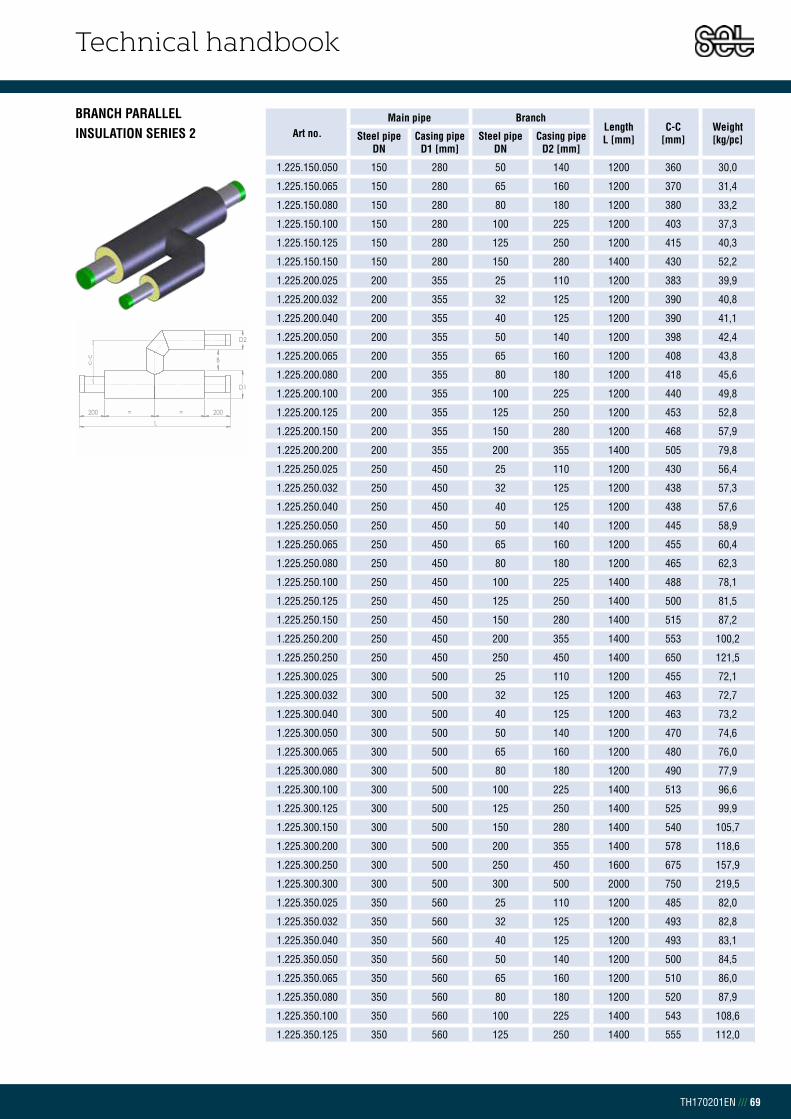
Technical handbook
TH170201EN /// 69
BRANCH PARALLELINSULATION SERIES 2 Art no.
Main pipe Branch Length L [mm]
C-C[mm]
Weight[kg/pc]Steel pipe
DNCasing pipe
D1 [mm]Steel pipe
DNCasing pipe
D2 [mm]
1.225.150.050 150 280 50 140 1200 360 30,0
1.225.150.065 150 280 65 160 1200 370 31,4
1.225.150.080 150 280 80 180 1200 380 33,2
1.225.150.100 150 280 100 225 1200 403 37,3
1.225.150.125 150 280 125 250 1200 415 40,3
1.225.150.150 150 280 150 280 1400 430 52,2
1.225.200.025 200 355 25 110 1200 383 39,9
1.225.200.032 200 355 32 125 1200 390 40,8
1.225.200.040 200 355 40 125 1200 390 41,1
1.225.200.050 200 355 50 140 1200 398 42,4
1.225.200.065 200 355 65 160 1200 408 43,8
1.225.200.080 200 355 80 180 1200 418 45,6
1.225.200.100 200 355 100 225 1200 440 49,8
1.225.200.125 200 355 125 250 1200 453 52,8
1.225.200.150 200 355 150 280 1200 468 57,9
1.225.200.200 200 355 200 355 1400 505 79,8
1.225.250.025 250 450 25 110 1200 430 56,4
1.225.250.032 250 450 32 125 1200 438 57,3
1.225.250.040 250 450 40 125 1200 438 57,6
1.225.250.050 250 450 50 140 1200 445 58,9
1.225.250.065 250 450 65 160 1200 455 60,4
1.225.250.080 250 450 80 180 1200 465 62,3
1.225.250.100 250 450 100 225 1400 488 78,1
1.225.250.125 250 450 125 250 1400 500 81,5
1.225.250.150 250 450 150 280 1400 515 87,2
1.225.250.200 250 450 200 355 1400 553 100,2
1.225.250.250 250 450 250 450 1400 650 121,5
1.225.300.025 300 500 25 110 1200 455 72,1
1.225.300.032 300 500 32 125 1200 463 72,7
1.225.300.040 300 500 40 125 1200 463 73,2
1.225.300.050 300 500 50 140 1200 470 74,6
1.225.300.065 300 500 65 160 1200 480 76,0
1.225.300.080 300 500 80 180 1200 490 77,9
1.225.300.100 300 500 100 225 1400 513 96,6
1.225.300.125 300 500 125 250 1400 525 99,9
1.225.300.150 300 500 150 280 1400 540 105,7
1.225.300.200 300 500 200 355 1400 578 118,6
1.225.300.250 300 500 250 450 1600 675 157,9
1.225.300.300 300 500 300 500 2000 750 219,5
1.225.350.025 350 560 25 110 1200 485 82,0
1.225.350.032 350 560 32 125 1200 493 82,8
1.225.350.040 350 560 40 125 1200 493 83,1
1.225.350.050 350 560 50 140 1200 500 84,5
1.225.350.065 350 560 65 160 1200 510 86,0
1.225.350.080 350 560 80 180 1200 520 87,9
1.225.350.100 350 560 100 225 1400 543 108,6
1.225.350.125 350 560 125 250 1400 555 112,0
L200 200
D2
D1
= =
c-c
L200 200
D2
D1
B
= =
c-c

Technical handbook
TH170201EN /// 70
BRANCH PARALLELINSULATION SERIES 2 Art no.
Main pipe Branch Length L [mm]
C-C[mm]
Weight[kg/pc]Steel pipe
DNCasing pipe
D1 [mm]Steel pipe
DNCasing pipe
D2 [mm]
1.225.350.150 350 560 150 280 1400 570 117,8
1.225.350.200 350 560 200 355 1400 608 131,0
1.225.350.250 350 560 250 450 1600 655 170,0
1.225.350.300 350 560 300 500 2000 780 238,3
1.225.350.350 350 560 350 560 2000 810 255,5
1.225.400.040 400 630 40 125 1200 528 105,0
1.225.400.050 400 630 50 140 1200 535 106,3
1.225.400.065 400 630 65 160 1200 545 107,8
1.225.400.080 400 630 80 180 1200 555 109,8
1.225.400.100 400 630 100 225 1400 578 134,6
1.225.400.125 400 630 125 250 1400 590 138,0
1.225.400.150 400 630 150 280 1400 605 143,9
1.225.400.200 400 630 200 355 1400 643 157,1
1.225.400.250 400 630 250 450 1600 690 200,4
1.225.400.300 400 630 300 500 2000 815 276,9
1.225.400.350 400 630 350 560 2000 845 294,3
1.225.400.400 400 630 400 630 2000 930 334,4
1.225.450.050 450 710 40 125 1200 528 111,8
1.225.450.065 450 710 50 140 1200 535 113,2
1.225.450.080 450 710 65 160 1200 545 114,6
1.225.450.100 450 710 80 180 1200 555 116,5
1.225.450.125 450 710 100 225 1400 578 142,2
1.225.450.150 450 710 125 250 1400 590 145,6
1.225.450.200 450 710 150 280 1400 605 151,3
1.225.450.250 450 710 200 355 1400 643 164,2
1.225.450.300 450 710 250 450 1600 790 213,1
1.225.450.350 450 710 300 500 2000 815 286,1
1.225.450.400 450 710 350 560 2000 845 303,3
1.225.450.450 450 710 400 630 2000 930 242,9
1.225.450.450 450 710 450 710 2000 1030 361,7
1.225.500.040 500 800 40 125 1200 568 129,8
1.225.500.050 500 800 50 140 1200 575 131,2
1.225.500.065 500 800 65 160 1200 585 132,6
1.225.500.080 500 800 80 180 1200 595 134,5
1.225.500.100 500 800 100 225 1400 618 164,0
1.225.500.125 500 800 125 250 1400 630 167,4
1.225.500.150 500 800 150 280 1400 645 173,2
1.225.500.200 500 800 200 355 1400 683 186,3
1.225.500.250 500 800 250 450 1600 830 239,0
1.225.500.300 500 800 300 500 2000 855 319,7
1.225.500.350 500 800 350 560 2000 885 336,9
1.225.500.400 500 800 400 630 2000 970 376,8
1.225.500.450 500 800 450 710 2000 1020 390,7
1.225.500.500 500 800 500 800 2000 1110 431,7
1.225.600.065 600 900 65 160 1200 630 169,1
1.225.600.080 600 900 80 180 1200 640 171,0
1.225.600.100 600 900 100 225 1400 663 206,8
L200 200
D2
D1
= =
c-c
L200 200
D2
D1
B
= =
c-c
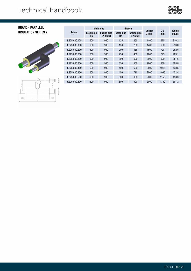
Technical handbook
TH170201EN /// 71
BRANCH PARALLELINSULATION SERIES 2 Art no.
Main pipe Branch Length L [mm]
C-C[mm]
Weight[kg/pc]Steel pipe
DNCasing pipe
D1 [mm]Steel pipe
DNCasing pipe
D2 [mm]
1.225.600.125 600 900 125 250 1400 675 210,2
1.225.600.150 600 900 150 280 1400 690 216,0
1.225.600.200 600 900 200 355 1600 728 262,6
1.225.600.250 600 900 250 450 1600 775 283,1
1.225.600.300 600 900 300 500 2000 900 381,6
1.225.600.350 600 900 350 560 2000 930 398,8
1.225.600.400 600 900 400 630 2000 1015 438,5
1.225.600.450 600 900 450 710 2000 1065 452,4
1.225.600.500 600 900 500 800 2000 1155 493,3
1.225.600.600 600 900 600 900 2000 1350 581,2
L200 200
D2
D1
= =
c-c
L200 200
D2
D1
B
= =
c-c

Technical handbook
TH170201EN /// 72
BRANCH PARALLELINSULATION SERIES 3 Art no.
Main pipe Branch Length L [mm]
C-C[mm]
Weight[kg/pc]Steel pipe
DNCasing pipe
D1 [mm]Steel pipe
DNCasing pipe
D2 [mm]
1.325.020.020 20 125 20 125 1000 275 5,1
1.325.025.020 25 125 20 125 1000 275 5,5
1.325.025.025 25 125 25 125 1000 275 5,8
1.325.032.020 32 140 20 125 1000 275 6,2
1.325.032.025 32 140 25 125 1000 283 6,6
1.325.032.032 32 140 32 140 1000 290 7,3
1.325.040.020 40 140 20 125 1000 283 6,6
1.325.040.025 40 140 25 125 1000 283 6,9
1.325.040.032 40 140 32 140 1000 290 7,6
1.325.040.040 40 140 40 140 1000 290 7,9
1.325.050.020 50 160 20 125 1000 293 8,1
1.325.050.025 50 160 25 125 1000 293 8,4
1.325.050.032 50 160 32 140 1000 300 9,1
1.325.050.040 50 160 40 140 1000 300 9,4
1.325.050.050 50 160 50 160 1000 310 10,7
1.325.065.020 65 180 20 125 1000 303 9,6
1.325.065.025 65 180 25 125 1000 303 9,9
1.325.065.032 65 180 32 140 1000 310 10,6
1.325.065.040 65 180 40 140 1000 310 10,9
1.325.065.065 65 180 50 160 1000 320 12,2
1.325.065.050 65 180 65 180 1000 330 13,5
1.325.080.020 80 200 20 125 1000 313 11,6
1.325.080.025 80 200 25 125 1000 313 11,8
1.325.080.032 80 200 32 140 1000 320 12,5
1.325.080.040 80 200 40 140 1000 320 12,8
1.325.080.050 80 200 50 160 1000 330 14,0
1.325.080.065 80 200 65 180 1000 340 15,4
1.325.080.080 80 200 80 200 1000 350 17,0
1.325.100.025 100 250 25 125 1000 338 16,2
1.325.100.032 100 250 32 140 1000 345 16,8
1.325.100.040 100 250 40 140 1000 345 17,2
1.325.100.050 100 250 50 160 1200 355 22,3
1.325.100.065 100 250 65 180 1200 365 23,9
1.325.100.080 100 250 80 200 1200 375 25,7
1.325.100.100 100 250 100 250 1200 400 30,5
1.325.125.025 125 280 25 125 1200 353 23,6
1.325.125.032 125 280 32 140 1200 360 24,4
1.325.125.040 125 280 40 140 1200 360 24,7
1.325.125.050 125 280 50 160 1200 370 26,2
1.325.125.065 125 280 65 180 1200 380 27,7
1.325.125.080 125 280 80 200 1200 390 29,6
1.325.125.100 125 280 100 250 1200 415 34,3
1.325.125.125 125 280 125 280 1200 430 37,8
1.325.150.025 150 315 25 125 1200 370 29,9
1.325.150.032 150 315 32 140 1200 378 30,7
1.325.150.040 150 315 40 140 1200 378 31,0
1.325.150.050 150 315 50 160 1200 388 32,4
L200 200
D2
D1
= =
c-c
L200 200
D2
D1
B
= =
c-c

Technical handbook
TH170201EN /// 73
BRANCH PARALLELINSULATION SERIES 3 Art no.
Main pipe Branch Length L [mm]
C-C[mm]
Weight[kg/pc]Steel pipe
DNCasing pipe
D1 [mm]Steel pipe
DNCasing pipe
D2 [mm]
1.325.150.065 150 315 65 180 1200 398 34,0
1.325.150.080 150 315 80 200 1200 408 35,9
1.325.150.100 150 315 100 250 1200 433 40,6
1.325.150.125 150 315 125 280 1200 448 44,1
1.325.150.150 150 315 150 315 1400 465 57,4
1.325.200.025 200 400 25 125 1200 413 43,5
1.325.200.032 200 400 32 140 1200 420 44,3
1.325.200.040 200 400 40 140 1200 420 44,6
1.325.200.050 200 400 50 160 1200 430 46,1
1.325.200.065 200 400 65 180 1200 440 47,6
1.325.200.080 200 400 80 200 1200 450 49,6
1.325.200.100 200 400 100 250 1200 475 54,4
1.325.200.125 200 400 125 280 1200 490 57,9
1.325.200.150 200 400 150 315 1200 508 63,7
1.325.200.200 200 400 200 400 1400 550 88,9
1.325.250.025 250 500 25 125 1200 463 61,2
1.325.250.032 250 500 32 140 1200 470 62,0
1.325.250.040 250 500 40 140 1200 470 62,4
1.325.250.050 250 500 50 160 1200 480 63,9
1.325.250.065 250 500 65 180 1200 490 65,5
1.325.250.080 250 500 80 200 1200 500 67,5
1.325.250.100 250 500 100 250 1400 525 85,2
1.325.250.125 250 500 125 280 1400 540 89,2
1.325.250.150 250 500 150 315 1400 558 95,6
1.325.250.200 250 500 200 400 1400 600 110,9
1.325.250.250 250 500 250 500 1400 650 132,3
1.325.300.025 300 560 25 125 1200 493 78,4
1.325.300.032 300 560 32 140 1200 500 78,9
1.325.300.040 300 560 40 140 1200 500 79,5
1.325.300.050 300 560 50 160 1200 510 81,1
1.325.300.065 300 560 65 180 1200 520 82,7
1.325.300.080 300 560 80 200 1200 530 84,7
1.325.300.100 300 560 100 250 1400 555 105,6
1.325.300.125 300 560 125 280 1400 570 109,6
1.325.300.150 300 560 150 315 1400 588 116,1
1.325.300.200 300 560 200 400 1400 630 131,4
1.325.300.250 300 560 250 500 1600 680 131,4
1.325.300.300 300 560 300 560 2000 710 238,2
1.325.350.025 350 630 25 125 1200 528 89,8
1.325.350.032 350 630 32 140 1200 535 90,5
1.325.350.040 350 630 40 140 1200 535 91,0
1.325.350.050 350 630 50 160 1200 545 92,6
1.325.350.065 350 630 65 180 1200 555 94,3
1.325.350.080 350 630 80 200 1200 565 96,3
1.325.350.100 350 630 100 250 1400 590 119,8
1.325.350.125 350 630 125 280 1400 605 123,8
1.325.350.150 350 630 150 315 1400 623 130,4
L200 200
D2
D1
= =
c-c
L200 200
D2
D1
B
= =
c-c

Technical handbook
TH170201EN /// 74
BRANCH PARALLELINSULATION SERIES 3 Art no.
Main pipe Branch Length L [mm]
C-C[mm]
Weight[kg/pc]Steel pipe
DNCasing pipe
D1 [mm]Steel pipe
DNCasing pipe
D2 [mm]
1.325.350.200 350 630 200 400 1400 665 146,0
1.325.350.250 350 630 250 500 1600 715 190,2
1.325.350.300 350 630 300 560 2000 745 260,6
1.325.350.350 350 630 350 630 2000 780 281,0
1.325.400.040 400 710 40 140 1200 575 116,7
1.325.400.050 400 710 50 160 1200 585 118,3
1.325.400.065 400 710 65 180 1200 595 120,0
1.325.400.080 400 710 80 200 1200 605 122,0
1.325.400.100 400 710 100 250 1400 630 150,6
1.325.400.125 400 710 125 280 1400 645 154,7
1.325.400.150 400 710 150 315 1400 663 161,4
1.325.400.200 400 710 200 400 1400 705 177,1
1.325.400.250 400 710 250 500 1600 755 226,6
1.325.400.300 400 710 300 560 2000 785 307,3
1.325.400.350 400 710 350 630 2000 820 327,8
1.325.400.400 400 710 400 710 2000 910 375,9
1.325.450.050 450 800 40 140 1200 575 123,6
1.325.450.065 450 800 50 160 1200 585 125,1
1.325.450.080 450 800 65 180 1200 595 126,8
1.325.450.100 450 800 80 200 1200 605 128,8
1.325.450.125 450 800 100 250 1400 630 158,2
1.325.450.150 450 800 125 280 1400 645 162,2
1.325.450.200 450 800 150 315 1400 663 168,7
1.325.450.250 450 800 200 400 1400 705 184,1
1.325.450.300 450 800 250 500 1600 755 234,1
1.325.450.350 450 800 300 560 2000 785 316,4
1.325.450.400 450 800 350 630 2000 870 340,8
1.325.450.450 450 800 400 710 2000 860 389,5
1.325.450.450 450 800 450 800 2000 1010 404,2
1.325.500.040 500 900 40 140 1200 620 141,1
1.325.500.050 500 900 50 160 1200 630 142,7
1.325.500.065 500 900 65 180 1200 640 144,3
1.325.500.080 500 900 80 200 1200 650 146,4
1.325.500.100 500 900 100 250 1400 675 179,4
1.325.500.125 500 900 125 280 1400 690 183,5
1.325.500.150 500 900 150 315 1400 708 190,2
1.325.500.200 500 900 200 400 1400 750 205,8
1.325.500.250 500 900 250 500 1600 800 259,7
1.325.500.300 500 900 300 560 2000 830 349,4
1.325.500.350 500 900 350 630 2000 865 369,9
1.325.500.400 500 900 400 710 2000 955 417,8
1.325.500.450 500 900 450 800 2000 1055 438,0
1.325.500.500 500 900 500 900 2000 1150 480,6
1.325.600.065 600 1000 65 180 1200 690 183,2
1.325.600.080 600 1000 80 200 1200 700 185,2
1.325.600.100 600 1000 100 250 1400 725 225,3
1.325.600.125 600 1000 125 280 1400 740 229,4
L200 200
D2
D1
= =
c-c
L200 200
D2
D1
B
= =
c-c

Technical handbook
TH170201EN /// 75
BRANCH PARALLELINSULATION SERIES 3 Art no.
Main pipe Branch Length L [mm]
C-C[mm]
Weight[kg/pc]Steel pipe
DNCasing pipe
D1 [mm]Steel pipe
DNCasing pipe
D2 [mm]
1.325.600.150 600 1000 150 315 1400 758 236,1
1.325.600.200 600 1000 200 400 1600 800 288,9
1.325.600.250 600 1000 250 500 1600 850 312,7
1.325.600.300 600 1000 300 560 2000 880 416,4
1.325.600.350 600 1000 350 630 2000 915 436,8
1.325.600.400 600 1000 400 710 2000 1055 490,2
1.325.600.450 600 1000 450 800 2000 1105 505,0
1.325.600.500 600 1000 500 900 2000 1200 547,5
1.325.600.600 600 1000 600 1000 2000 1350 637,5
L200 200
D2
D1
= =
c-c
L200 200
D2
D1
B
= =
c-c

Technical handbook
TH170201EN /// 76
CHAPTER 2.9.5BRANCH STRAIGHTINSULATION SERIES 1
Art no. Steel Pipe Casing pipe Length
L1/L2[mm]
Weight[kg/pc]Steel pipe
DNCasing pipe
D1 [mm]Steel pipe
DNCasing pipe
D2 [mm]
1.120.020.020 20 90 20 90 1000/800 4,1
1.120.025.020 25 90 20 90 1000/800 4,5
1.120.025.025 25 90 25 90 1000/800 4,8
1.120.032.020 32 110 20 90 1000/800 5,2
1.120.032.025 32 110 25 90 1000/800 5,6
1.120.032.032 32 110 32 110 1000/800 6,2
1.120.040.020 40 110 20 90 1000/800 5,6
1.120.040.025 40 110 25 90 1000/800 5,9
1.120.040.032 40 110 32 110 1000/800 6,5
1.120.040.040 40 110 40 110 1000/800 6,8
1.120.050.020 50 125 20 90 1000/800 7,0
1.120.050.025 50 125 25 90 1000/800 7,3
1.120.050.032 50 125 32 110 1000/800 7,9
1.120.050.040 50 125 40 110 1000/800 8,2
1.120.050.050 50 125 50 125 1000/800 9,3
1.120.065.020 65 140 20 90 1000/800 8,3
1.120.065.025 65 140 25 90 1000/800 8,6
1.120.065.032 65 140 32 110 1000/800 9,2
1.120.065.040 65 140 40 110 1000/800 9,5
1.120.065.050 65 140 50 125 1000/800 10,6
1.120.065.065 65 140 65 140 1000/800 11,6
1.120.080.020 80 160 20 90 1000/800 10,3
1.120.080.025 80 160 25 90 1000/800 10,4
1.120.080.032 80 160 32 110 1000/800 11,0
1.120.080.040 80 160 40 110 1000/800 11,2
1.120.080.050 80 160 50 125 1000/800 12,3
1.120.080.065 80 160 65 140 1000/800 13,3
1.120.080.080 80 160 80 160 1000/800 14,7
1.120.100.025 100 200 25 90 1000/800 14,0
1.120.100.032 100 200 32 110 1000/800 14,6
1.120.100.040 100 200 40 110 1000/800 14,9
1.120.100.050 100 200 50 125 1000/800 16,0
1.120.100.065 100 200 65 140 1000/800 17,0
1.120.100.080 100 200 80 160 1000/800 18,3
1.120.100.100 100 200 100 200 1200/800 23,8
1.120.125.025 125 225 25 90 1000/800 16,7
1.120.125.032 125 225 32 110 1000/800 17,2
1.120.125.040 125 225 40 110 1000/800 17,5
1.120.125.050 125 225 50 125 1000/800 18,6
1.120.125.065 125 225 65 140 1000/800 19,6
1.120.125.080 125 225 80 160 1000/800 20,9
1.120.125.100 125 225 100 200 1200/800 26,9
1.120.125.125 125 225 125 225 1200/800 28,9
1.120.150.025 150 250 25 90 1000/800 21,2
1.120.150.032 150 250 32 110 1000/800 21,7
1.120.150.040 150 250 40 110 1000/800 22,0
1.120.150.050 150 250 50 125 1000/800 23,1
200
D2
D1
L1
200
L2
200
200
D2
D1
L1
200
L2
200
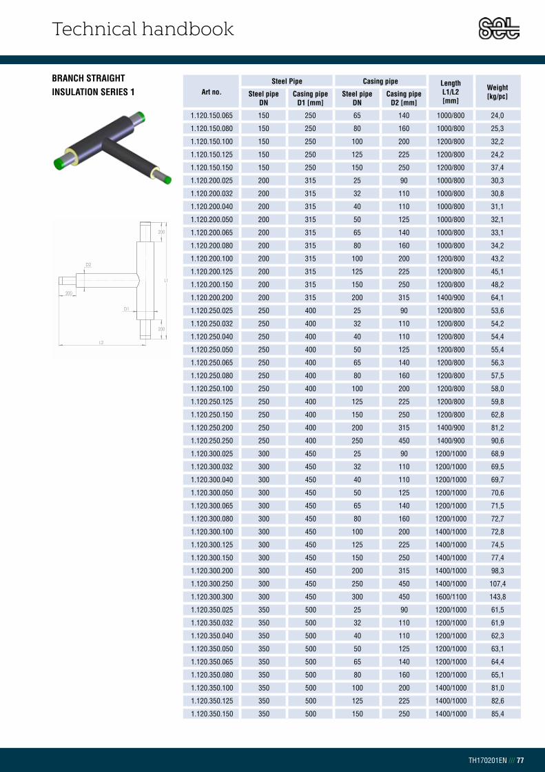
Technical handbook
TH170201EN /// 77
BRANCH STRAIGHTINSULATION SERIES 1 Art no.
Steel Pipe Casing pipe Length L1/L2[mm]
Weight[kg/pc]Steel pipe
DNCasing pipe
D1 [mm]Steel pipe
DNCasing pipe
D2 [mm]
1.120.150.065 150 250 65 140 1000/800 24,0
1.120.150.080 150 250 80 160 1000/800 25,3
1.120.150.100 150 250 100 200 1200/800 32,2
1.120.150.125 150 250 125 225 1200/800 24,2
1.120.150.150 150 250 150 250 1200/800 37,4
1.120.200.025 200 315 25 90 1000/800 30,3
1.120.200.032 200 315 32 110 1000/800 30,8
1.120.200.040 200 315 40 110 1000/800 31,1
1.120.200.050 200 315 50 125 1000/800 32,1
1.120.200.065 200 315 65 140 1000/800 33,1
1.120.200.080 200 315 80 160 1000/800 34,2
1.120.200.100 200 315 100 200 1200/800 43,2
1.120.200.125 200 315 125 225 1200/800 45,1
1.120.200.150 200 315 150 250 1200/800 48,2
1.120.200.200 200 315 200 315 1400/900 64,1
1.120.250.025 250 400 25 90 1200/800 53,6
1.120.250.032 250 400 32 110 1200/800 54,2
1.120.250.040 250 400 40 110 1200/800 54,4
1.120.250.050 250 400 50 125 1200/800 55,4
1.120.250.065 250 400 65 140 1200/800 56,3
1.120.250.080 250 400 80 160 1200/800 57,5
1.120.250.100 250 400 100 200 1200/800 58,0
1.120.250.125 250 400 125 225 1200/800 59,8
1.120.250.150 250 400 150 250 1200/800 62,8
1.120.250.200 250 400 200 315 1400/900 81,2
1.120.250.250 250 400 250 450 1400/900 90,6
1.120.300.025 300 450 25 90 1200/1000 68,9
1.120.300.032 300 450 32 110 1200/1000 69,5
1.120.300.040 300 450 40 110 1200/1000 69,7
1.120.300.050 300 450 50 125 1200/1000 70,6
1.120.300.065 300 450 65 140 1200/1000 71,5
1.120.300.080 300 450 80 160 1200/1000 72,7
1.120.300.100 300 450 100 200 1400/1000 72,8
1.120.300.125 300 450 125 225 1400/1000 74,5
1.120.300.150 300 450 150 250 1400/1000 77,4
1.120.300.200 300 450 200 315 1400/1000 98,3
1.120.300.250 300 450 250 450 1400/1000 107,4
1.120.300.300 300 450 300 450 1600/1100 143,8
1.120.350.025 350 500 25 90 1200/1000 61,5
1.120.350.032 350 500 32 110 1200/1000 61,9
1.120.350.040 350 500 40 110 1200/1000 62,3
1.120.350.050 350 500 50 125 1200/1000 63,1
1.120.350.065 350 500 65 140 1200/1000 64,4
1.120.350.080 350 500 80 160 1200/1000 65,1
1.120.350.100 350 500 100 200 1400/1000 81,0
1.120.350.125 350 500 125 225 1400/1000 82,6
1.120.350.150 350 500 150 250 1400/1000 85,4
200
D2
D1
L1
200
L2
200
200
D2
D1
L1
200
L2
200

Technical handbook
TH170201EN /// 78
BRANCH STRAIGHTINSULATION SERIES 1 Art no.
Steel Pipe Casing pipe Length L1/L2[mm]
Weight[kg/pc]Steel pipe
DNCasing pipe
D1 [mm]Steel pipe
DNCasing pipe
D2 [mm]
1.120.350.200 350 500 200 315 1400/1000 107,8
1.120.350.250 350 500 250 400 1400/1000 114,7
1.120.350.300 350 500 300 450 1600/1100 162,0
1.120.350.350 350 500 350 500 1600/1100 188,0
1.120.400.040 400 560 40 110 1200/1000 96,7
1.120.400.050 400 560 50 125 1200/1000 97,9
1.120.400.065 400 560 65 140 1200/1000 98,9
1.120.400.080 400 560 80 160 1200/1000 100,4
1.120.400.100 400 560 100 200 1400/1000 120,7
1.120.400.125 400 560 125 225 1400/1000 122,9
1.120.400.150 400 560 150 250 1400/1000 126,4
1.120.400.200 400 560 200 315 1400/1000 134,0
1.120.400.250 400 560 250 400 1400/1000 144,1
1.120.400.300 400 560 300 450 1600/1100 181,7
1.120.400.350 400 560 350 500 1600/1100 188,5
1.120.400.400 400 560 400 560 1800/1100 215,4
1.120.450.050 450 630 40 110 1200/1000 103,6
1.120.450.065 450 630 50 125 1200/1000 104,8
1.120.450.080 450 630 65 140 1200/1000 105,8
1.120.450.100 450 630 80 160 1200/1000 107,3
1.120.450.125 450 630 100 200 1400/1000 128,4
1.120.450.150 450 630 125 225 1400/1000 130,5
1.120.450.200 450 630 150 250 1400/1000 134,1
1.120.450.250 450 630 200 315 1400/1000 141,4
1.120.450.300 450 630 250 400 1400/1000 151,2
1.120.450.350 450 630 300 450 1600/1100 188,4
1.120.450.400 450 630 350 500 1600/1100 195,1
1.120.450.450 450 630 400 560 1800/1100 223,7
1.120.450.450 450 630 450 630 1800/1100 228,7
1.120.500.040 500 710 40 110 1200/1000 117,6
1.120.500.050 500 710 50 125 1200/1000 118,7
1.120.500.065 500 710 65 140 1200/1000 119,7
1.120.500.080 500 710 80 160 1200/1000 121,1
1.120.500.100 500 710 100 200 1400/1000 144,9
1.120.500.125 500 710 125 225 1400/1000 146,9
1.120.500.150 500 710 150 250 1400/1000 150,3
1.120.500.200 500 710 200 315 1400/1000 157,4
1.120.500.250 500 710 250 400 1400/1000 166,9
1.120.500.300 500 710 300 450 1600/1100 207,2
1.120.500.350 500 710 350 500 1600/1100 213,7
1.120.500.400 500 710 400 560 1800/1100 243,8
1.120.500.450 500 710 450 630 1800/1100 248,6
1.120.500.500 500 710 500 710 1800/1100 258,4
1.120.600.065 600 800 65 140 1200/1200 157,8
1.120.600.080 600 800 80 160 1200/1200 159,5
1.120.600.100 600 800 100 200 1400/1200 190,5
1.120.600.125 600 800 125 225 1400/1200 193,1
200
D2
D1
L1
200
L2
200
200
D2
D1
L1
200
L2
200

Technical handbook
TH170201EN /// 79
BRANCH STRAIGHTINSULATION SERIES 1 Art no.
Steel Pipe Casing pipe Length L1/L2[mm]
Weight[kg/pc]Steel pipe
DNCasing pipe
D1 [mm]Steel pipe
DNCasing pipe
D2 [mm]
1.120.600.150 600 800 150 250 1400/1200 197,2
1.120.600.200 600 800 200 315 1600/1200 233,3
1.120.600.250 600 800 250 400 1600/1200 245,0
1.120.600.300 600 800 300 450 1600/1200 260,3
1.120.600.350 600 800 350 500 1600/1200 267,2
1.120.600.400 600 800 400 560 1800/1200 305,4
1.120.600.450 600 800 450 630 1800/1200 210,2
1.120.600.500 600 800 500 710 1800/1200 320,8
1.120.600.600 600 800 600 800 2000/1200 375,8
200
D2
D1
L1
200
L2
200
200
D2
D1
L1
200
L2
200

Technical handbook
TH170201EN /// 80
BRANCH STRAIGHTINSULATION SERIES 2 Art no.
Steel Pipe Casing pipe Length L1/L2[mm]
Weight[kg/pc]Steel pipe
DNCasing pipe
D1 [mm]Steel pipe
DNCasing pipe
D2 [mm]
1.220.020.020 20 110 20 110 1000/800 4,5
1.220.025.020 25 110 20 110 1000/800 4,9
1.220.025.025 25 110 25 110 1000/800 5,3
1.220.032.020 32 125 20 110 1000/800 5,6
1.220.032.025 32 125 25 110 1000/800 6,1
1.220.032.032 32 125 32 125 1000/800 6,7
1.220.040.020 40 125 20 110 1000/800 6,1
1.220.040.025 40 125 25 110 1000/800 6,4
1.220.040.032 40 125 32 125 1000/800 7,1
1.220.040.040 40 125 40 125 1000/800 7,4
1.220.050.020 50 140 20 110 1000/800 7,5
1.220.050.025 50 140 25 110 1000/800 7,8
1.220.050.032 50 140 32 125 1000/800 8,5
1.220.050.040 50 140 40 125 1000/800 8,2
1.220.050.050 50 140 50 140 1000/800 9,8
1.220.065.020 65 160 20 110 1000/800 8,8
1.220.065.025 65 160 25 110 1000/800 9,2
1.220.065.032 65 160 32 125 1000/800 9,8
1.220.065.040 65 160 40 125 1000/800 10,1
1.220.065.050 65 160 50 140 1000/800 11,2
1.220.065.065 65 160 65 160 1000/800 12,2
1.220.080.020 80 180 20 110 1000/800 11,0
1.220.080.025 80 180 25 110 1000/800 11,1
1.220.080.032 80 180 32 125 1000/800 11,7
1.220.080.040 80 180 40 125 1000/800 11,9
1.220.080.050 80 180 50 140 1000/800 13,0
1.220.080.065 80 180 65 160 1000/800 14,1
1.220.080.080 80 180 80 180 1200/800 18,2
1.220.100.025 100 225 25 110 1000/800 14,9
1.220.100.032 100 225 32 125 1000/800 15,4
1.220.100.040 100 225 40 125 1000/800 15,8
1.220.100.050 100 225 50 140 1000/800 16,9
1.220.100.065 100 225 65 160 1000/800 17,9
1.220.100.080 100 225 80 180 1200/800 23,3
1.220.100.100 100 225 100 225 1200/800 25,2
1.220.125.025 125 250 25 110 1000/800 17,7
1.220.125.032 125 250 32 125 1000/800 18,2
1.220.125.040 125 250 40 125 1000/800 18,6
1.220.125.050 125 250 50 140 1000/800 19,6
1.220.125.065 125 250 65 160 1000/800 20,6
1.220.125.080 125 250 80 180 1200/800 26,7
1.220.125.100 125 250 100 225 1200/800 28,5
1.220.125.125 125 250 125 250 1200/800 30,5
1.220.150.025 150 280 25 110 1000/800 22,5
1.220.150.032 150 280 32 125 1000/800 22,9
1.220.150.040 150 280 40 125 1000/800 23,3
1.220.150.050 150 280 50 140 1000/800 24,3
200
D2
D1
L1
200
L2
200
200
D2
D1
L1
200
L2
200

Technical handbook
TH170201EN /// 81
BRANCH STRAIGHTINSULATION SERIES 2 Art no.
Steel Pipe Casing pipe Length L1/L2[mm]
Weight[kg/pc]Steel pipe
DNCasing pipe
D1 [mm]Steel pipe
DNCasing pipe
D2 [mm]
1.220.150.065 150 280 65 160 1000/800 25,4
1.220.150.080 150 280 80 180 1200/800 32,6
1.220.150.100 150 280 100 225 1200/800 34,1
1.220.150.125 150 280 125 250 1200/800 36,2
1.220.150.150 150 280 150 280 1200/800 39,6
1.220.200.025 200 355 25 110 1000/800 32,4
1.220.200.032 200 355 32 125 1000/800 32,8
1.220.200.040 200 355 40 125 1000/800 33,2
1.220.200.050 200 355 50 140 1000/800 34,1
1.220.200.065 200 355 65 160 1000/800 35,1
1.220.200.080 200 355 80 180 1200/800 45,3
1.220.200.100 200 355 100 225 1200/800 46,1
1.220.200.125 200 355 125 250 1200/800 48,1
1.220.200.150 200 355 150 280 1200/800 51,4
1.220.200.200 200 355 200 355 1400/900 68,6
1.220.250.025 250 450 25 110 1200/800 58,6
1.220.250.032 250 450 32 125 1200/800 59,2
1.220.250.040 250 450 40 125 1200/800 59,4
1.220.250.050 250 450 50 140 1200/800 60,4
1.220.250.065 250 450 65 160 1200/800 61,3
1.220.250.080 250 450 80 180 1200/800 62,6
1.220.250.100 250 450 100 225 1200/800 62,2
1.220.250.125 250 450 125 250 1200/800 64,0
1.220.250.150 250 450 150 280 1200/800 67,2
1.220.250.200 250 450 200 355 1400/900 87,3
1.220.250.250 250 450 250 450 1400/900 97,2
1.220.300.025 300 500 25 110 1200/1000 74,5
1.220.300.032 300 500 32 125 1200/1000 75,1
1.220.300.040 300 500 40 125 1200/1000 75,3
1.220.300.050 300 500 50 140 1200/1000 76,2
1.220.300.065 300 500 65 160 1200/1000 77,2
1.220.300.080 300 500 80 180 1200/1000 78,4
1.220.300.100 300 500 100 225 1400/1000 77,6
1.220.300.125 300 500 125 250 1400/1000 79,3
1.220.300.150 300 500 150 280 1400/1000 82,4
1.220.300.200 300 500 200 355 1400/1000 104,9
1.220.300.250 300 500 250 450 1400/1000 113,3
1.220.300.300 300 500 300 500 1600/1100 155,4
1.220.350.025 350 560 25 110 1200/1000 65,4
1.220.350.032 350 560 32 125 1200/1000 66,4
1.220.350.040 350 560 40 125 1200/1000 66,8
1.220.350.050 350 560 50 140 1200/1000 67,7
1.220.350.065 350 560 65 160 1200/1000 68,5
1.220.350.080 350 560 80 180 1200/1000 69,7
1.220.350.100 350 560 100 225 1400/1000 87,2
1.220.350.125 350 560 125 250 1400/1000 88,9
1.220.350.150 350 560 150 280 1400/1000 91,8
200
D2
D1
L1
200
L2
200
200
D2
D1
L1
200
L2
200

Technical handbook
TH170201EN /// 82
BRANCH STRAIGHTINSULATION SERIES 2 Art no.
Steel Pipe Casing pipe Length L1/L2[mm]
Weight[kg/pc]Steel pipe
DNCasing pipe
D1 [mm]Steel pipe
DNCasing pipe
D2 [mm]
1.220.350.200 350 560 200 355 1400/1000 116,3
1.220.350.250 350 560 250 500 1600/1000 151,8
1.220.350.300 350 560 300 560 1600/1100 175,6
1.220.350.350 350 560 350 560 1800/1100 184,9
1.220.400.040 400 630 40 125 1200/1000 104,3
1.220.400.050 400 630 50 140 1200/1000 105,5
1.220.400.065 400 630 65 160 1200/1000 106,6
1.220.400.080 400 630 80 180 1200/1000 108,2
1.220.400.100 400 630 100 225 1400/1000 130,5
1.220.400.125 400 630 125 250 1400/1000 132,8
1.220.400.150 400 630 150 280 1400/1000 135,5
1.220.400.200 400 630 200 355 1400/1000 144,8
1.220.400.250 400 630 250 450 1600/1000 181,5
1.220.400.300 400 630 300 500 1600/1100 198,6
1.220.400.350 400 630 350 560 1800/1100 217,1
1.220.400.400 400 630 400 630 1800/1100 232,8
1.220.450.050 450 710 40 125 1200/1000 111,3
1.220.450.065 450 710 50 140 1200/1000 112,4
1.220.450.080 450 710 65 160 1200/1000 113,5
1.220.450.100 450 710 80 180 1200/1000 115,0
1.220.450.125 450 710 100 225 1400/1000 138,2
1.220.450.150 450 710 125 250 1400/1000 140,5
1.220.450.200 450 710 150 280 1400/1000 144,2
1.220.450.250 450 710 200 355 1400/1000 152,2
1.220.450.300 450 710 250 450 1600/1000 188,5
1.220.450.350 450 710 300 500 1600/1100 205,3
1.220.450.400 450 710 350 560 1800/1100 225,7
1.220.450.450 450 710 400 630 1800/1100 241,2
1.220.450.450 450 710 450 710 1800/1100 246,3
1.220.500.040 500 710 40 125 1200/1000 129,0
1.220.500.050 500 800 50 140 1200/1000 130,1
1.220.500.065 500 800 65 160 1200/1000 131,2
1.220.500.080 500 800 80 180 1200/1000 132,7
1.220.500.100 500 800 100 225 1400/1000 159,4
1.220.500.125 500 800 125 250 1400/1000 161,6
1.220.500.150 500 800 150 280 1400/1000 165,2
1.220.500.200 500 800 200 355 1400/1000 172,3
1.220.500.250 500 800 250 450 1600/1000 213,8
1.220.500.300 500 800 300 500 1600/1100 230,2
1.220.500.350 500 800 350 560 1800/1100 252,9
1.220.500.400 500 800 400 630 1800/1100 267,8
1.220.500.450 500 800 450 710 1800/1100 272,7
1.220.500.500 500 800 500 800 1800/1100 284,6
1.220.600.065 600 900 65 160 1200/1200 169,0
1.220.600.080 600 900 80 180 1200/1200 170,8
1.220.600.100 600 900 100 225 1400/1200 204,7
1.220.600.125 600 900 125 250 1400/1200 207,3
200
D2
D1
L1
200
L2
200
200
D2
D1
L1
200
L2
200

Technical handbook
TH170201EN /// 83
BRANCH STRAIGHTINSULATION SERIES 2 Art no.
Steel Pipe Casing pipe Length L1/L2[mm]
Weight[kg/pc]Steel pipe
DNCasing pipe
D1 [mm]Steel pipe
DNCasing pipe
D2 [mm]
1.220.600.150 600 900 150 280 1400/1200 211,8
1.220.600.200 600 900 200 355 1600/1200 251,3
1.220.600.250 600 900 250 450 1600/1200 263,9
1.220.600.300 600 900 300 500 1600/1200 283,7
1.220.600.350 600 900 350 560 1800/1200 313,1
1.220.600.400 600 900 400 630 1800/1200 329,1
1.220.600.450 600 900 450 710 1800/1200 334,1
1.220.600.500 600 900 500 800 1800/1200 347,2
1.220.600.600 600 900 600 900 2000/1200 403,8
200
D2
D1
L1
200
L2
200
200
D2
D1
L1
200
L2
200

Technical handbook
TH170201EN /// 84
BRANCH STRAIGHTINSULATION SERIES 3 Art no.
Steel Pipe Casing pipe Length L1/L2[mm]
Weight[kg/pc]Steel pipe
DNCasing pipe
D1 [mm]Steel pipe
DNCasing pipe
D2 [mm]
1.320.020.020 20 125 20 125 1000/800 5,1
1.320.025.020 25 125 20 125 1000/800 5,5
1.320.025.025 25 125 25 125 1000/800 5,8
1.320.032.020 32 140 20 125 1000/800 6,2
1.320.032.025 32 140 25 125 1000/800 6,6
1.320.032.032 32 140 32 140 1000/800 7,2
1.320.040.020 40 140 20 125 1000/800 6,6
1.320.040.025 40 140 25 125 1000/800 6,9
1.320.040.032 40 140 32 140 1000/800 7,6
1.320.040.040 40 140 40 140 1000/800 7,8
1.320.050.020 50 160 20 125 1000/800 8,1
1.320.050.025 50 160 25 125 1000/800 8,4
1.320.050.032 50 160 32 140 1000/800 9,0
1.320.050.040 50 160 40 140 1000/800 9,3
1.320.050.050 50 160 50 160 1000/800 10,4
1.320.065.020 65 180 20 125 1000/800 9,5
1.320.065.025 65 180 25 125 1000/800 9,9
1.320.065.032 65 180 32 140 1000/800 10,5
1.320.065.040 65 180 40 140 1000/800 10,8
1.320.065.050 65 180 50 160 1000/800 11,9
1.320.065.065 65 180 65 180 1000/800 13,0
1.320.080.020 80 200 20 125 1000/800 11,3
1.320.080.025 80 200 25 125 1000/800 11,5
1.320.080.032 80 200 32 140 1000/800 11,7
1.320.080.040 80 200 40 140 1000/800 12,6
1.320.080.050 80 200 50 160 1000/800 13,7
1.320.080.065 80 200 65 180 1000/800 14,8
1.320.080.080 80 200 80 200 1200/800 19,3
1.320.100.025 100 250 25 125 1000/800 16,0
1.320.100.032 100 250 32 140 1000/800 16,4
1.320.100.040 100 250 40 140 1000/800 16,8
1.320.100.050 100 250 50 160 1000/800 17,9
1.320.100.065 100 250 65 180 1000/800 19,1
1.320.100.080 100 250 80 200 1200/800 28,3
1.320.100.100 100 250 100 250 1200/800 26,9
1.320.125.025 125 280 25 125 1000/800 18,6
1.320.125.032 125 280 32 140 1000/800 18,0
1.320.125.040 125 280 40 140 1000/800 18,4
1.320.125.050 125 280 50 160 1000/800 20,5
1.320.125.065 125 280 65 180 1000/800 21,6
1.320.125.080 125 280 80 200 1200/800 28,3
1.320.125.100 125 280 100 250 1200/800 30,0
1.320.125.125 125 280 125 280 1200/800 32,7
1.320.150.025 150 315 25 125 1000/800 24,1
1.320.150.032 150 315 32 140 1000/800 24,4
1.320.150.040 150 315 40 140 1000/800 24,9
1.320.150.050 150 315 50 160 1000/800 25,9
200
D2
D1
L1
200
L2
200
200
D2
D1
L1
200
L2
200

Technical handbook
TH170201EN /// 85
BRANCH STRAIGHTINSULATION SERIES 3 Art no.
Steel Pipe Casing pipe Length L1/L2[mm]
Weight[kg/pc]Steel pipe
DNCasing pipe
D1 [mm]Steel pipe
DNCasing pipe
D2 [mm]
1.320.150.065 150 315 65 180 1000/800 27,1
1.320.150.080 150 315 80 200 1200/800 35,3
1.320.150.100 150 315 100 250 1200/800 26,6
1.320.150.125 150 315 125 280 1200/800 28,8
1.320.150.150 150 315 150 315 1200/800 42,4
1.320.200.025 200 400 25 125 1000/800 34,9
1.320.200.032 200 400 32 140 1000/800 35,2
1.320.200.040 200 400 40 140 1000/800 35,7
1.320.200.050 200 400 50 160 1000/800 36,7
1.320.200.065 200 400 65 180 1000/800 37,8
1.320.200.080 200 400 80 200 1200/800 49,5
1.320.200.100 200 400 100 250 1200/800 49,7
1.320.200.125 200 400 125 280 1200/800 51,8
1.320.200.150 200 400 150 315 1200/800 55,3
1.320.200.200 200 400 200 400 1400/900 74,1
1.320.250.025 250 500 25 125 1200/800 64,2
1.320.250.032 250 500 32 140 1200/800 64,8
1.320.250.040 250 500 40 140 1200/800 65,0
1.320.250.050 250 500 50 160 1200/800 66,1
1.320.250.065 250 500 65 180 1200/800 67,1
1.320.250.080 250 500 80 200 1200/800 68,4
1.320.250.100 250 500 100 250 1200/800 66,9
1.320.250.125 250 500 125 280 1200/800 68,9
1.320.250.150 250 500 150 315 1200/800 72,3
1.320.250.200 250 500 200 400 1400/900 94,2
1.320.250.250 250 500 250 500 1400/900 104,6
1.320.300.025 300 560 25 125 1200/1000 62,8
1.320.300.032 300 560 32 140 1200/1000 63,0
1.320.300.040 300 560 40 140 1200/1000 63,5
1.320.300.050 300 560 50 160 1200/1000 64,5
1.320.300.065 300 560 65 180 1200/1000 65,5
1.320.300.080 300 560 80 200 1200/1000 66,7
1.320.300.100 300 560 100 250 1400/1000 83,8
1.320.300.125 300 560 125 280 1400/1000 85,7
1.320.300.150 300 560 150 315 1400/1000 88,9
1.320.300.200 300 560 200 400 1400/1000 113,7
1.320.300.250 300 560 250 500 1600/1000 145,8
1.320.300.300 300 560 300 560 1600/1100 170,9
1.320.350.025 350 630 25 125 1200/1000 71,8
1.320.350.032 350 630 32 140 1200/1000 71,9
1.320.350.040 350 630 40 140 1200/1000 72,4
1.320.350.050 350 630 50 160 1200/1000 73,4
1.320.350.065 350 630 65 180 1200/1000 74,5
1.320.350.080 350 630 80 200 1200/1000 75,5
1.320.350.100 350 630 100 250 1400/1000 94,9
1.320.350.125 350 630 125 280 1400/1000 96,8
1.320.350.150 350 630 150 315 1400/1000 99,9
200
D2
D1
L1
200
L2
200
200
D2
D1
L1
200
L2
200
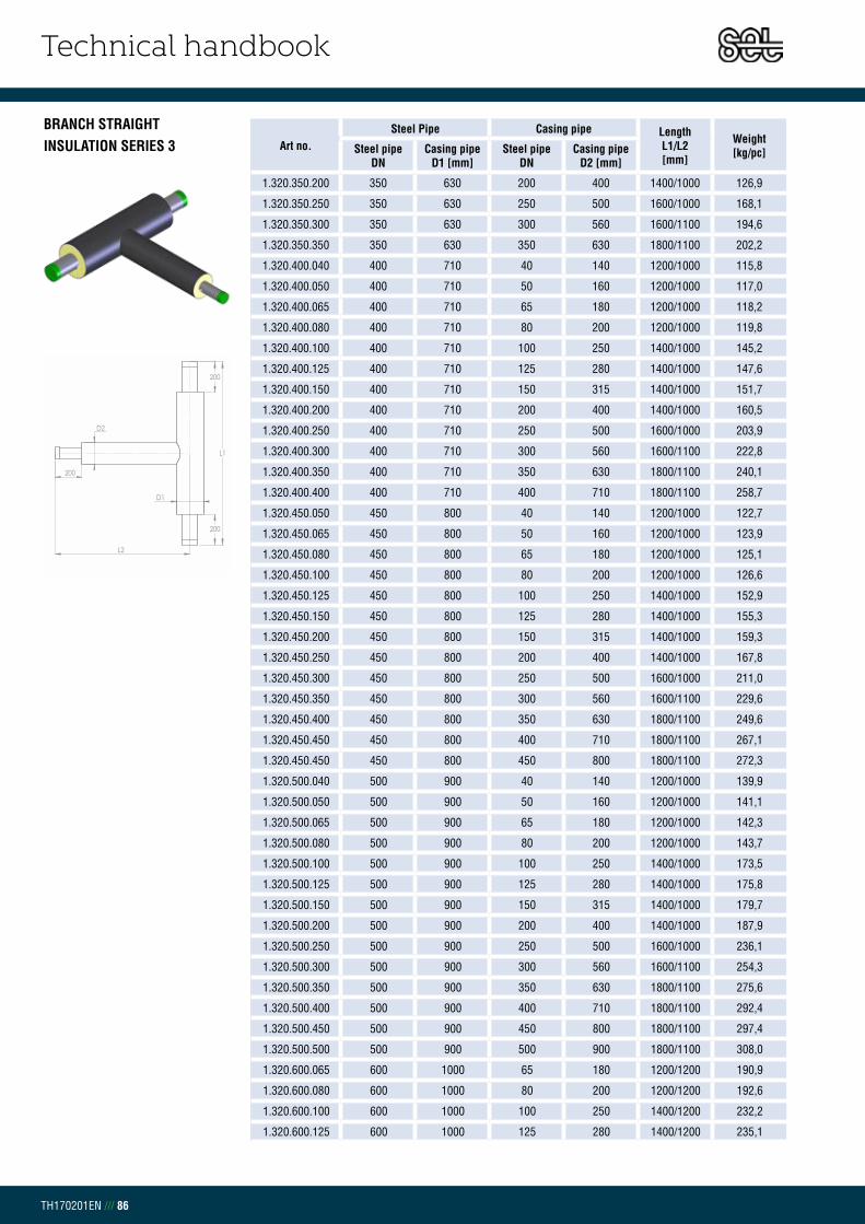
Technical handbook
TH170201EN /// 86
BRANCH STRAIGHTINSULATION SERIES 3 Art no.
Steel Pipe Casing pipe Length L1/L2[mm]
Weight[kg/pc]Steel pipe
DNCasing pipe
D1 [mm]Steel pipe
DNCasing pipe
D2 [mm]
1.320.350.200 350 630 200 400 1400/1000 126,9
1.320.350.250 350 630 250 500 1600/1000 168,1
1.320.350.300 350 630 300 560 1600/1100 194,6
1.320.350.350 350 630 350 630 1800/1100 202,2
1.320.400.040 400 710 40 140 1200/1000 115,8
1.320.400.050 400 710 50 160 1200/1000 117,0
1.320.400.065 400 710 65 180 1200/1000 118,2
1.320.400.080 400 710 80 200 1200/1000 119,8
1.320.400.100 400 710 100 250 1400/1000 145,2
1.320.400.125 400 710 125 280 1400/1000 147,6
1.320.400.150 400 710 150 315 1400/1000 151,7
1.320.400.200 400 710 200 400 1400/1000 160,5
1.320.400.250 400 710 250 500 1600/1000 203,9
1.320.400.300 400 710 300 560 1600/1100 222,8
1.320.400.350 400 710 350 630 1800/1100 240,1
1.320.400.400 400 710 400 710 1800/1100 258,7
1.320.450.050 450 800 40 140 1200/1000 122,7
1.320.450.065 450 800 50 160 1200/1000 123,9
1.320.450.080 450 800 65 180 1200/1000 125,1
1.320.450.100 450 800 80 200 1200/1000 126,6
1.320.450.125 450 800 100 250 1400/1000 152,9
1.320.450.150 450 800 125 280 1400/1000 155,3
1.320.450.200 450 800 150 315 1400/1000 159,3
1.320.450.250 450 800 200 400 1400/1000 167,8
1.320.450.300 450 800 250 500 1600/1000 211,0
1.320.450.350 450 800 300 560 1600/1100 229,6
1.320.450.400 450 800 350 630 1800/1100 249,6
1.320.450.450 450 800 400 710 1800/1100 267,1
1.320.450.450 450 800 450 800 1800/1100 272,3
1.320.500.040 500 900 40 140 1200/1000 139,9
1.320.500.050 500 900 50 160 1200/1000 141,1
1.320.500.065 500 900 65 180 1200/1000 142,3
1.320.500.080 500 900 80 200 1200/1000 143,7
1.320.500.100 500 900 100 250 1400/1000 173,5
1.320.500.125 500 900 125 280 1400/1000 175,8
1.320.500.150 500 900 150 315 1400/1000 179,7
1.320.500.200 500 900 200 400 1400/1000 187,9
1.320.500.250 500 900 250 500 1600/1000 236,1
1.320.500.300 500 900 300 560 1600/1100 254,3
1.320.500.350 500 900 350 630 1800/1100 275,6
1.320.500.400 500 900 400 710 1800/1100 292,4
1.320.500.450 500 900 450 800 1800/1100 297,4
1.320.500.500 500 900 500 900 1800/1100 308,0
1.320.600.065 600 1000 65 180 1200/1200 190,9
1.320.600.080 600 1000 80 200 1200/1200 192,6
1.320.600.100 600 1000 100 250 1400/1200 232,2
1.320.600.125 600 1000 125 280 1400/1200 235,1
200
D2
D1
L1
200
L2
200
200
D2
D1
L1
200
L2
200

Technical handbook
TH170201EN /// 87
BRANCH STRAIGHTINSULATION SERIES 3 Art no.
Steel Pipe Casing pipe Length L1/L2[mm]
Weight[kg/pc]Steel pipe
DNCasing pipe
D1 [mm]Steel pipe
DNCasing pipe
D2 [mm]
1.320.600.150 600 1000 150 315 1400/1200 239,7
1.320.600.200 600 1000 200 400 1600/1200 285,2
1.320.600.250 600 1000 250 500 1600/1200 298,1
1.320.600.300 600 1000 300 560 1800/1200 345,8
1.320.600.350 600 1000 350 630 1800/1200 353,7
1.320.600.400 600 1000 400 710 1800/1200 371,2
1.320.600.450 600 1000 450 800 1800/1200 376,3
1.320.600.500 600 1000 500 900 1800/1200 387,9
1.320.600.600 600 1000 600 1000 2000/1200 436,7
200
D2
D1
L1
200
L2
200
200
D2
D1
L1
200
L2
200

Technical handbook
TH170201EN /// 88
CHAPTER 2.9.6REDUCTIONINSULATION SERIES 1
Art no. Steel Pipe DN
Casing pipe D1/D2 [mm]
Length L [mm]
Weight[kg/pc]
1.130.025.020 25-20 90/90 1000 3,0
1.130.032.020 32-20 110/90 1000 3,5
1.130.032.025 32-25 110/90 1000 3,7
1.130.040.025 40-25 110/90 1000 3,8
1.130.040.032 40-32 110/110 1000 4,3
1.130.050.025 50-25 125/90 1000 4,6
1.130.050.032 50-32 125/110 1000 5,0
1.130.050.040 50-40 125/110 1000 5,2
1.130.065.040 65-40 140/110 1000 5,9
1.130.065.050 65-50 140/125 1000 6,6
1.130.080.050 80-50 160/125 1000 7,6
1.130.080.065 80-65 160/140 1000 8,3
1.130.100.065 100-65 200/140 1000 10,4
1.130.100.080 100-80 200/160 1000 11,4
1.130.125.080 125-80 225/160 1000 13,5
1.130.125.100 125-100 225/200 1000 14,9
1.130.150.100 150-100 250/200 1000 17,2
1.130.150.125 150-125 250/225 1000 18,7
1.130.200.125 200-125 315/225 1000 23,6
1.130.200.150 200-150 315/250 1000 25,9
1.130.250.150 250-150 400/250 1500 48,9
1.130.250.200 250-200 400/315 1500 56,3
1.130.300.200 300-200 450/315 1500 65,9
1.130.300.250 300-250 450/400 1500 75,9
1.130.350.250 350-250 500/400 1500 81,5
1.130.350.300 350-300 500/450 1500 91,2
1.130.400.300 400-300 560/450 1500 104,0
1.130.400.350 400-350 560/500 1500 109,6
1.130.450.350 450-350 630/500 1500 119,2
1.130.450.400 450-400 630/560 1500 132,0
1.130.500.400 500-400 710/560 1500 135,3
1.130.500.450 500-450 710/630 1500 138,9
1.130.600.450 600-450 800/630 1500 160,6
1.130.600.500 600-500 800/710 1500 169,9

Technical handbook
TH170201EN /// 89
REDUCTIONINSULATION SERIES 2
Art no. Steel Pipe DN
Casing pipe D1/D2 [mm]
Length L [mm]
Weight[kg/pc]
1.230.025.020 25-20 110/110 1000 3,4
1.230.032.020 32-20 125/110 1000 3,7
1.230.032.025 32-25 125/110 1000 3,9
1.230.040.025 40-25 125/110 1000 4,2
1.230.040.032 40-32 125/125 1000 4,5
1.230.050.025 50-25 140/110 1000 5,0
1.230.050.032 50-32 140/125 1000 5,2
1.230.050.040 50-40 140/125 1000 5,4
1.230.065.040 65-40 160/125 1000 6,4
1.230.065.050 65-50 160/140 1000 7,1
1.230.080.050 80-50 180/140 1000 8,1
1.230.080.065 80-65 180/160 1000 8,9
1.230.100.065 100-65 225/160 1000 11,2
1.230.100.080 100-80 225/180 1000 12,2
1.230.125.080 125-80 250/180 1000 13,7
1.230.125.100 125-100 250/225 1000 16,0
1.230.150.100 150-100 280/225 1000 18,6
1.230.150.125 150-125 280/250 1000 20,1
1.230.200.125 200-125 355/250 1000 25,5
1.230.200.150 200-150 355/280 1000 28,1
1.230.250.150 250-150 450/280 1500 53,2
1.230.250.200 250-200 450/355 1500 61,4
1.230.300.200 300-200 500/355 1500 71,4
1.230.300.250 300-250 500/450 1500 82,5
1.230.350.250 350-250 560/450 1500 89,1
1.230.350.300 350-300 560/500 1500 99,1
1.230.400.300 400-300 630/500 1500 113,4
1.230.400.350 400-350 630/560 1500 120,1
1.230.450.350 450-350 710/560 1500 123,6
1.230.450.400 450-400 710/630 1500 138,0
1.230.500.400 500-400 800/630 1500 148,9
1.230.500.450 500-450 800/710 1500 152,5
1.230.600.450 600-450 900/710 1500 176,2
1.230.600.500 600-500 900/800 1500 187,1

Technical handbook
TH170201EN /// 90
REDUCTIONINSULATION SERIES 3
Art no. Steel Pipe DN
Casing pipe D1/D2 [mm]
Length L [mm]
Weight[kg/pc]
1.330.025.020 25-20 125/125 1000 3,8
1.330.032.020 32-20 140/125 1000 4,1
1.330.032.025 32-25 140/125 1000 4,3
1.330.040.025 40-25 140/125 1000 4,6
1.330.040.032 40-32 140/140 1000 4,9
1.330.050.025 50-25 160/125 1000 5,5
1.330.050.032 50-32 160/140 1000 5,7
1.330.050.040 50-40 160/140 1000 6,1
1.330.065.040 65-40 180/140 1000 6,9
1.330.065.050 65-50 180/160 1000 7,7
1.330.080.050 80-50 200/160 1000 8,8
1.330.080.065 80-65 200/180 1000 9,6
1.330.100.065 100-65 250/180 1000 12,1
1.330.100.080 100-80 250/200 1000 13,2
1.330.125.080 125-80 280/200 1000 14,9
1.330.125.100 125-100 280/250 1000 17,4
1.330.150.100 150-100 315/250 1000 20,2
1.330.150.125 150-125 315/280 1000 18,7
1.330.200.125 200-125 400/280 1000 28,0
1.330.200.150 200-150 400/315 1000 30,7
1.330.250.200 250-150 500/315 1500 58,1
1.330.250.250 250-200 500/400 1500 67,3
1.330.300.200 300-200 560/400 1500 78,3
1.330.300.250 300-250 560/500 1500 90,4
1.330.350.250 350-250 630/500 1500 98,5
1.330.350.300 350-300 630/560 1500 109,6
1.330.400.300 400-300 710/560 1500 125,5
1.330.400.350 400-350 710/630 1500 133,7
1.330.450.350 450-350 800/630 1500 137,2
1.330.450.400 450-400 800/710 1500 153,1
1.330.500.400 500-400 900/710 1500 166,1
1.330.500.450 500-450 900/800 1500 169,7
1.330.600.450 600-450 1000/800 1500 195,8
1.330.600.500 600-500 1000/900 1500 208,8
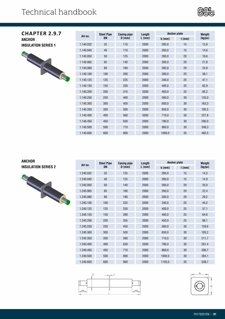
Technical handbook
TH170201EN /// 91
CHAPTER 2.9.7ANCHORINSULATION SERIES 1
Art no. Steel Pipe DN
Casing pipe D [mm]
Length L [mm]
Anchor plate Weight[kg/pc]b [mm] t [mm]
1.140.032 32 110 2000 260,0 15 13,9
1.140.040 40 110 2000 260,0 15 14,6
1.140.050 50 125 2000 260,0 20 19,6
1.140.065 65 140 2000 260,0 20 21,8
1.140.080 80 160 2000 260,0 20 24,9
1.140.100 100 200 2000 300,0 25 38,1
1.140.125 125 225 2000 340,0 25 47,1
1.140.150 150 250 2000 400,0 25 62,9
1.140.200 200 315 2000 450,0 25 85,2
1.140.250 250 400 2000 560,0 30 135,0
1.140.300 300 450 2000 600,0 30 163,3
1.140.350 350 500 2000 650,0 30 185,5
1.140.400 400 560 2000 710,0 30 227,8
1.140.450 450 630 2000 780,0 30 295,0
1.140.500 500 710 2000 860,0 30 346,3
1.140.600 600 800 2000 1000,0 35 465,5
ANCHORINSULATION SERIES 2 Art no. Steel Pipe
DNCasing pipe
D [mm]Length L [mm]
Anchor plate Weight[kg/pc]b [mm] t [mm]
1.240.032 32 125 2000 260,0 15 14,3
1.240.040 40 125 2000 260,0 15 14,9
1.240.050 50 140 2000 260,0 20 20,0
1.240.065 65 160 2000 260,0 20 22,4
1.240.080 80 180 2000 300,0 20 29,2
1.240.100 100 225 2000 340,0 25 44,2
1.240.125 125 250 2000 400,0 25 57,1
1.240.150 150 280 2000 400,0 25 64,6
1.240.200 200 355 2000 450,0 25 88,1
1.240.250 250 450 2000 560,0 30 139,6
1.240.300 300 500 2000 650,0 30 183,2
1.240.350 350 560 2000 710,0 30 211,7
1.240.400 400 630 2000 780,0 30 261,4
1.240.450 450 710 2000 860,0 30 306,7
1.240.500 500 800 2000 1000,0 30 384,1
1.240.600 600 900 2000 1150,0 35 538,7

Technical handbook
TH170201EN /// 92
ANCHORINSULATION SERIES 3 Art no. Steel Pipe
DNCasing pipe
D [mm]Length L [mm]
Anchor plate Weight[kg/pc]b [mm] t [mm]
1.340.032 32 140 2000 260 15 14,7
1.340.040 40 140 2000 260 15 15,4
1.340.050 50 160 2000 260 20 20,7
1.340.065 65 180 2000 300 20 26,7
1.340.080 80 200 2000 300 20 30,0
1.340.100 100 250 2000 400 25 54,2
1.340.125 125 280 2000 400 25 58,8
1.340.150 150 315 2000 400 25 66,9
1.340.200 200 400 2000 560 25 113,6
1.340.250 250 500 2000 650 30 170,4
1.340.300 300 560 2000 710 30 209,3
1.340.350 350 630 2000 780 30 245,3
1.340.400 400 710 2000 860 30 304,0
1.340.450 450 800 2000 1000 30 382,9
1.340.500 500 900 2000 1150 30 478,6
1.340.600 600 1000 2000 1250 35 604,7

Technical handbook
TH170201EN /// 93
CHAPTER 2.9.8VALVEINSULATION SERIES 1
Art no. Steel PipeDN
Casing pipeD [mm]
Spindle height H [mm]
LengthL1 [mm]
Weight[kg/pc]
1.145.025 25 90 382 1500 7,9
1.145.032 32 110 388 1500 10,5
1.145.040 40 110 401 1500 11,4
1.145.050 50 125 411 1500 13,9
1.145.065 65 140 415 1500 19,2
1.145.080 80 160 426 1500 23,9
1.145.100 100 200 450 1500 37,7
1.145.125 125 225 455 1500 51,6
1.145.150 150 250 475 1500 62,5
1.145.200 200 315 520 1500 93,1
1.145.250 250 400 557 1500 146,5
1.145.300 300 450 664 1800 256,1
1.145.350 350 500 830 1800 328,6
1.145.400 400 560 830 1800 435,8
1.145.450 450 630 900 1800 784,1
1.145.500 500 710 1000 1800 907,8
1.145.600 600 800 1075 2000 1973,3
VALVEINSULATION SERIES 2
Art no. Steel PipeDN
Casing pipeD [mm]
Spindle height H [mm]
LengthL1 [mm]
Weight[kg/pc]
1.245.025 25 110 382 1500 8,6
1.245.032 32 125 388 1500 11,1
1.245.040 40 125 401 1500 12,0
1.245.050 50 140 411 1500 14,5
1.245.065 65 160 415 1500 20,2
1.245.080 80 180 426 1500 25,0
1.245.100 100 225 450 1500 39,4
1.245.125 125 250 455 1500 53,5
1.245.150 150 280 475 1500 65,1
1.245.200 200 355 520 1500 97,4
1.245.250 250 450 557 1500 153,1
1.245.300 300 500 664 1800 266,7
1.245.350 350 560 830 1800 342,5
1.245.400 400 630 830 1800 454,3
1.245.450 450 710 900 1800 802,6
1.245.500 500 800 1000 1800 931,3
1.245.600 600 900 1075 2000 2010,1
D
200L1
200
H

Technical handbook
TH170201EN /// 94
VALVEINSULATION SERIES 3
Art no. Steel PipeDN
Casing pipeD [mm]
Spindle height H [mm]
LengthL1 [mm]
Weight[kg/pc]
1.345.025 25 125 382 1500 9,1
1.345.032 32 140 388 1500 11,7
1.345.040 40 140 401 1500 12,7
1.345.050 50 160 411 1500 15,4
1.345.065 65 180 415 1500 21,2
1.345.080 80 200 426 1500 26,3
1.345.100 100 250 450 1500 41,3
1.345.125 125 280 455 1500 56,2
1.345.150 150 315 475 1500 68,4
1.345.200 200 400 520 1500 102,6
1.345.250 250 500 557 1500 160,5
1.345.300 300 560 664 1800 280,6
1.345.350 350 630 830 1800 361,0
1.345.400 400 710 830 1800 477,8
1.345.450 450 800 900 1800 826,0
1.345.500 500 900 1000 1800 961,0
1.345.600 600 1000 1075 2000 2056,1
D
200L1
200
H
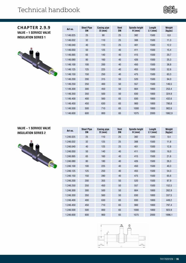
Technical handbook
TH170201EN /// 95
CHAPTER 2.9.9VALVE – 1 SERVICE VALVEINSULATION SERIES 1
Art no. Steel PipeDN
Casing pipe D [mm]
VentDN
Spindle heightH [mm]
LengthL1 [mm]
Weight[kg/pc]
1.146.025 25 90 25 382 1500 8,8
1.146.032 32 110 25 388 1500 11,3
1.146.040 40 110 25 401 1500 12,2
1.146.050 50 125 40 411 1500 15,4
1.146.065 65 140 40 415 1500 20,7
1.146.080 80 160 40 426 1500 25,3
1.146.100 100 200 40 450 1500 38,8
1.146.125 125 225 40 455 1500 52,6
1.146.150 150 250 40 475 1500 63,3
1.146.200 200 315 50 520 1500 94,0
1.146.250 250 400 50 557 1500 146,5
1.146.300 300 450 50 664 1800 253,4
1.146.350 350 500 50 830 1800 324,9
1.146.400 400 560 65 830 1800 432,6
1.146.450 450 630 65 900 1800 780,8
1.146.500 500 710 65 1000 1800 902,6
1.146.600 600 800 65 1075 2000 1962,9
VALVE – 1 SERVICE VALVEINSULATION SERIES 2
Art no. Steel PipeDN
Casing pipe D [mm]
VentDN
Spindle heightH [mm]
LengthL1 [mm]
Weight[kg/pc]
1.246.025 25 110 25 382 1500 9,4
1.246.032 32 125 25 388 1500 11,8
1.246.040 40 125 25 401 1500 12,8
1.246.050 50 140 40 411 1500 16,0
1.246.065 65 160 40 415 1500 21,6
1.246.080 80 180 40 426 1500 26,3
1.246.100 100 225 40 450 1500 40,3
1.246.125 125 250 40 455 1500 54,3
1.246.150 150 280 40 475 1500 65,6
1.246.200 200 355 50 520 1500 97,9
1.246.250 250 450 50 557 1500 152,5
1.246.300 300 500 50 664 1800 262,9
1.246.350 350 560 50 830 1800 337,5
1.246.400 400 630 65 830 1800 449,2
1.246.450 450 710 65 900 1800 797,4
1.246.500 500 800 65 1000 1800 923,9
1.246.600 600 900 65 1075 2000 1996,1

Technical handbook
TH170201EN /// 96
VALVE – 1 SERVICE VALVEINSULATION SERIES 3
Art no. Steel PipeDN
Casing pipe D [mm]
VentDN
Spindle heightH [mm]
LengthL1 [mm]
Weight[kg/pc]
1.346.025 25 125 25 382 1500 9,9
1.346.032 32 140 25 388 1500 12,4
1.346.040 40 140 25 401 1500 13,3
1.346.050 50 160 40 411 1500 16,8
1.346.065 65 180 40 415 1500 22,5
1.346.080 80 200 40 426 1500 27,4
1.346.100 100 250 40 450 1500 42,1
1.346.125 125 280 40 455 1500 56,6
1.346.150 150 315 40 475 1500 68,5
1.346.200 200 400 50 520 1500 102,6
1.346.250 250 500 50 557 1500 159,2
1.346.300 300 560 50 664 1800 275,5
1.346.350 350 630 50 830 1800 354,1
1.346.400 400 710 65 830 1800 470,4
1.346.450 450 800 65 900 1800 818,6
1.346.500 500 900 65 1000 1800 950,8

Technical handbook
TH170201EN /// 97
CHAPTER 2.9.10VALVE – 2 SERVICE VALVEINSULATION SERIES 1
Art no. Steel PipeDN
Casing pipeD [mm]
Vent DN
Spindle heightH [mm]
LengthL [mm]
Weight[kg/pc]
1.147.025 25 90 25 382 1500 10,1
1.147.032 32 110 25 388 1500 12,6
1.147.040 40 110 25 401 1500 13,5
1.147.050 50 125 40 411 1500 17,5
1.147.065 65 140 40 415 1500 22,8
1.147.080 80 160 40 426 1500 27,4
1.147.100 100 200 40 450 1500 40,9
1.147.125 125 225 40 455 1500 54,7
1.147.150 150 250 40 475 1500 65,4
1.147.200 200 315 50 520 1500 96,8
1.147.250 250 400 50 557 1500 149,4
1.147.300 300 450 50 664 1800 256,2
1.147.350 350 500 50 830 1800 327,7
1.147.400 400 560 65 830 1800 437,2
1.147.450 450 630 65 900 1800 785,4
1.147.500 500 710 65 1000 1800 907,3
VALVE – 2 SERVICE VALVEINSULATION SERIES 2
Art no. Steel PipeDN
Casing pipeD [mm]
Vent DN
Spindle heightH [mm]
LengthL [mm]
Weight[kg/pc]
1.247.025 25 110 25 382 1500 10,7
1.247.032 32 125 25 388 1500 13,1
1.247.040 40 125 25 401 1500 14,1
1.247.050 50 140 40 411 1500 18,1
1.247.065 65 160 40 415 1500 23,7
1.247.080 80 180 40 426 1500 28,3
1.247.100 100 225 40 450 1500 42,4
1.247.125 125 250 40 455 1500 56,4
1.247.150 150 280 40 475 1500 67,7
1.247.200 200 355 50 520 1500 100,7
1.247.250 250 450 50 557 1500 155,4
1.247.300 300 500 50 664 1800 265,7
1.247.350 350 560 50 830 1800 340,3
1.247.400 400 630 65 830 1800 453,8
1.247.450 450 710 65 900 1800 802,0
1.247.500 500 800 65 1000 1800 928,5

Technical handbook
TH170201EN /// 98
VALVE – 2 SERVICE VALVEINSULATION SERIES 3
Art no. Steel PipeDN
Casing pipeD [mm]
Vent DN
Spindle heightH [mm]
LengthL [mm]
Weight[kg/pc]
1.347.025 25 125 25 382 1500 11,2
1.347.032 32 140 25 388 1500 13,7
1.347.040 40 140 25 401 1500 14,6
1.347.050 50 160 40 411 1500 18,9
1.347.065 65 180 40 415 1500 24,6
1.347.080 80 200 40 426 1500 29,5
1.347.100 100 250 40 450 1500 44,1
1.347.125 125 280 40 455 1500 58,7
1.347.150 150 315 40 475 1500 70,6
1.347.200 200 400 50 520 1500 105,5
1.347.250 250 500 50 557 1500 162,0
1.347.300 300 560 50 664 1800 278,3
1.347.350 350 630 50 830 1800 356,9
1.347.400 400 710 65 830 1800 475,0
1.347.450 450 800 65 900 1800 823,3
1.347.500 500 900 65 1000 1800 955,4

Technical handbook
TH170201EN /// 99
CHAPTER 2.9.11SERVICE VALVEINSULATION SERIES 1
Art no. Steel Pipe DN
Casing pipe D [mm]
Vent DN
Length L [mm]
Weight[kg/pc]
1.155.025.025 25 90 25 1000 4,3
1.155.032.025 32 110 25 1000 5,2
1.155.040.025 40 110 25 1000 5,5
1.155.050.025 50 125 25 1000 6,9
1.155.065.040 65 140 25 1000 8,3
1.155.080.040 80 160 40 1000 10,9
1.155.100.040 100 200 40 1000 14,8
1.155.125.040 125 225 40 1000 17,6
1.155.150.040 150 250 40 1000 22,2
1.155.200.050 200 315 40 1000 31,6
1.155.250.050 250 400 50 1000 44,8
1.155.300.050 300 450 50 1000 57,4
1.155.355.050 350 500 50 1000 64,2
1.155.400.050 400 560 50 1000 80,6
1.155.450.050 450 630 65 1000 88,4
1.155.500.050 500 710 65 1000 100,0
1.155.600.050 600 800 65 1000 129,2
SERVICE VALVEINSULATION SERIES 2
Art no. Steel Pipe DN
Casing pipe D [mm]
Vent DN
Length L [mm]
Weight[kg/pc]
1.255.025.025 25 110 25 1000 4,7
1.255.032.025 32 125 25 1000 5,5
1.255.040.025 40 125 25 1000 5,8
1.255.050.025 50 140 25 1000 7,2
1.255.065.040 65 160 25 1000 8,7
1.255.080.040 80 180 40 1000 11,4
1.255.100.040 100 225 40 1000 15,6
1.255.125.040 125 250 40 1000 18,5
1.255.150.040 150 280 40 1000 23,4
1.255.200.050 200 355 40 1000 33,6
1.255.250.050 250 450 50 1000 47,8
1.255.300.050 300 500 50 1000 60,7
1.255.355.050 350 560 50 1000 68,4
1.255.400.050 400 630 50 1000 86,3
1.255.450.050 450 710 65 1000 94,1
1.255.500.050 500 800 65 1000 107,2
1.255.600.050 600 900 65 1000 138,3

Technical handbook
TH170201EN /// 100
SERVICE VALVEINSULATION SERIES 3
Art no. Steel Pipe DN
Casing pipe D [mm]
Vent DN
Length L [mm]
Weight[kg/pc]
1.355.025.025 25 125 25 1000 4,9
1.355.032.025 32 140 25 1000 5,8
1.355.040.025 40 140 25 1000 6,1
1.355.050.025 50 160 25 1000 7,7
1.355.065.040 65 180 25 1000 9,2
1.355.080.040 80 200 40 1000 12,0
1.355.100.040 100 250 40 1000 16,5
1.355.125.040 125 280 40 1000 19,7
1.355.150.040 150 315 40 1000 24,9
1.355.200.050 200 400 40 1000 35,9
1.355.250.050 250 500 50 1000 51,1
1.355.300.050 300 560 50 1000 64,9
1.355.355.050 350 630 50 1000 74,1
1.355.400.050 400 710 50 1000 93,5
1.355.450.050 450 800 65 1000 101,3
1.355.500.050 500 900 65 1000 116,3
1.355.600.050 600 1000 65 1000 149,7
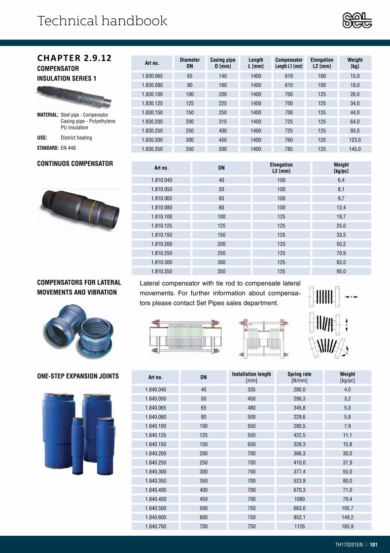
Technical handbook
TH170201EN /// 101
CHAPTER 2.9.12COMPENSATOR INSULATION SERIES 1
MATERIAL: Steel pipe - Compensator Casing pipe - Polyethylene PU insulation
USE: District heating
STANDARD: EN 448
Art no. Diameter DN
Casing pipeD [mm]
LengthL [mm]
Compensator Length L1 [mm]
Elongation L2 [mm]
Weight[kg]
1.830.065 65 140 1400 610 100 15,0
1.830.080 80 160 1400 610 100 18,0
1.830.100 100 200 1400 700 125 26,0
1.830.125 125 225 1400 700 125 34,0
1.830.150 150 250 1400 700 125 44,0
1.830.200 200 315 1400 725 125 64,0
1.830.250 250 400 1400 725 125 93,0
1.830.300 300 450 1400 760 125 123,0
1.830.350 350 500 1400 785 125 145,0
Art no. DN Elongation L2 [mm]
Weight [kg/pc]
1.810.040 40 100 6,4
1.810.050 50 100 8,1
1.810.065 65 100 9,7
1.810.080 80 100 12,4
1.810.100 100 125 19,7
1.810.125 125 125 25,0
1.810.150 150 125 33,5
1.810.200 200 125 50,2
1.810.250 250 125 70,9
1.810.300 300 125 83,0
1.810.350 350 125 95,0
Art no. DN Installation length[mm]
Spring rate[N/mm]
Weight [kg/pc]
1.840.040 40 335 280,0 4,0
1.840.050 50 450 290,3 3,2
1.840.065 65 480 345,8 5,0
1.840.080 80 500 229,6 5,8
1.840.100 100 550 280,5 7,9
1.840.125 125 550 422,5 11,1
1.840.150 150 630 328,3 15,8
1.840.200 200 700 366,3 30,0
1.840.250 250 700 410,0 37,9
1.840.300 300 700 377,4 55,0
1.840.350 350 700 523,9 80,0
1.840.400 400 700 670,3 71,0
1.840.450 450 700 1080 79,4
1.840.500 500 750 663,0 105,7
1.840.600 600 750 852,1 149,2
1.840.700 700 750 1126 165,9
Lateral compensator with tie rod to compensate lateral
movements. For further information about compensa-
tors please contact Set Pipes sales department.
ONE-STEP EXPANSION JOINTS
COMPENSATORS FOR LATERAL MOVEMENTS AND VIBRATION
CONTINUOS COMPENSATOR

Technical handbook
TH170201EN /// 102
CHAPTER 2.9.13STEEL BALL VALVESWELDING/WELDING
Art no. DN PN A[mm]
D1[mm]
D2[mm]
H[mm]
H1[mm]
L[mm]
S[mm]
Weight[kg/pc]
1.910.015 15 40 145 21,3 33,7 98 22 230 2,0 0,60
1.910.020 20 40 145,0 26,9 42,4 103 23 230 2,3 0,80
1.910.025 25 40 145,0 33,7 48,3 118 34 230 2,6 1,0
1.910.032 32 40 145,0 42,4 60,3 121 33 260 2,6 1,4
1.910.040 40 40 188,0 48,3 70,0 120 43 260 2,6 1,8
1.910.050 50 40 188,0 60,3 88,9 127 44 300 2,9 2,6
1.910.065 65 25 277,5 76,1 101,6 159 62 300 2,9 4,0
1.910.080 80 25 277,5 88,9 121,0 171 68 300 3,2 5,3
1.910.100 100 25 278,5 114,3 146,0 218 101 325 3,6 8,3
1.910.125 125 25 400,0 139,7 177,8 252 101 325 4,0 13,4
1.910.150 150 25 600,0 168,3 219,1 272 107 350 4,5 18,0
1.910.200 200 25 870,0 219,1 273,0 280 92 400 4,5 39,0
1.910.250 250 25 1200,0 273 355,6 350 108 530 5,0 74,0
STEEL BALL VALVESWELDING/WELDING
Art no. DN PN D[mm]
D1[mm]
D2[mm]
D3[mm]
H1[mm]
L[mm]
S[mm]
Weight[kg/pc]
1.910.300 300 25 250 323,9 457 50 133 550 5,6 110,0
1.910.350 350 25 290 355,6 508 50 192 686 5,6 170,0
1.910.400 400 25 340 406,4 610 70 242 762 7,0 250,0
1.910.500 500 25 390 508,0 660 90 259 914 7,0 400,0
1.910.600 600 25 486 610,0 813 90 274 1065 7,1 997,0

Technical handbook
TH170201EN /// 103
Art no. DN PN A[mm]
D[mm]
D1[mm]
D2[mm]
D3[BSP]
H[mm]
L[mm]
L1[mm]
S[mm]
Weight[kg/pc]
1.911.015 15 40 145 10 21,3 33,7 R ½ 98 158 115 2,0 0,60
1.911.020 20 40 145 15 26,9 42,4 R ¾ 103 165 115 2,3 0,80
1.911.025 25 40 145 20 33,7 48,3 R 1 118 172 115 2,6 1,1
1.911.032 32 40 145 25 42,4 60,3 R 1 ¼ 121 195 130 2,6 1,4
1.911.040 40 40 188 32 48,3 70,0 R 1 ½ 120 205 130 2,6 1,9
1.911.050 50 40 188 40 60,3 88,9 R 2 127 240 150 2,9 2,7
STEEL BALL VALVESFEMALE THREADS/WELDING

Technical handbook
TH170201EN /// 104
STEEL BALL VALVESFEMALE THREADS/ FEMALE THREADS
Art no. DN PN D1[mm]
D2[mm]
D3[mm]
H[mm]
L[mm]
S[mm]
HEX1
HEX2
Weight[kg/pc]
1.909.020 20 40 26,9 48,3 33,7 42 170 2,3 9 22 1,1
1.909.025 25 40 33,7 60,3 36,5 46 209 2,6 9 22 1,5
1.909.032 32 40 36,5 70,0 46,2 55 209 2,6 10 27 2,0
1.909.040 40 40 48,3 88,9 52,1 63 228 2,6 10 27 2,7
1.909.050 50 40 60,3 101,6 64,5 74 260 2,6 15 32 4,5
1.909.065 65 25 76,1 121,0 76,1 88 280 2,9 15 32 5,5
1.909.080 80 25 88,9 146,0 94,5 102 312 3,2 15 36 10,1
1.909.100 100 25 114,0 177,8 122,1 123 349 3,5 19 41 18,0
1.909.125 125 25 139,7 219,1 151,7 143 363 5,6 19 41 29,9
1.909.150 150 25 168,3 219,1 151,7 143 365 4,5 19 41 29,9
Art no. DN PN A[mm]
D[mm]
D1[BSP]
D2[mm]
H[mm]
H1[mm]
L[mm]
Weight[kg/pc]
1.912.015 15 40 145,0 10 R ½ 33,7 98 22 85 0,50
1.912.020 20 40 145,0 15 R ¾ 42,4 103 23 100 0,80
1.912.025 25 40 145,0 20 R 1 48,3 118 34 115 1,0
1.912.032 32 40 145,0 25 R 1 ¼ 60,3 121 33 130 1,2
1.912.040 40 40 188,0 32 R 1 ½ 70,0 120 43 150 1,8
1.912.050 50 40 188,0 40 R 2 88,9 127 44 180 2,6
SPECIAL PURPOSE BALL VALVES – HOT TAPPING VALVES

Technical handbook
TH170201EN /// 105
SPECIAL PURPOSE BALL VALVES – BRANCHING VALVE
Art no. DN PN D[mm]
D1[mm]
D2[mm]
H[mm]
L[mm]
S[mm]
HEX1
HEX2
Weight[kg/pc]
1.908.020 20 40 15 26,9 42,4 36 230 2,3 - 19,0 0,80
1.908.025 25 40 20 33,7 48,3 42 230 2,6 9 22,0 1,1
1.908.032 32 40 25 42,4 60,3 46 260 2,6 9 22,0 1,3
1.908.040 40 40 32 48,3 70,0 55 260 2,6 10 27,0 1,5
1.908.050 50 40 40 60,3 88,9 63 300 2,9 10 27,0 2,4
1.908.065 65 25 50 76,1 101,6 74 300 2,9 15 32,0 3,3
1.908.080 80 25 65 88,9 121,0 87 300 3,2 15 32,0 4,6
1.908.100 100 25 80 114,3 146,0 104 325 3,6 15 36,0 7,2
1.908.125 125 25 100 139,7 177,8 123 325 5,0 19 41,0 12,1
1.908.150 150 25 125 168,3 219,1 143 350 5,6 19 41,0 16,6
1.908.200 200 25 150 219,1 273,0 173 390 4,5 32 70,0 31,0

Technical handbook
TH170201EN /// 106
Art no. DN PN A[mm]
C[mm]
D1[mm]
D2[mm]
D3[mm]
E[mm]
L[mm]
S[mm]
Weight[kg/pc]
1.915.100 100 25 186 53 114,3 146 125 239 325 3,6 18
1.915.125 125 25 224 53 139,7 177,8 200 259 325 4,0 20
1.915.150 150 25 224 53 168,3 219,1 200 279 350 4,1 25
1.915.200 200 25 268 69 219,1 273,0 250 293 400 4,5 49
1.915.250 250 25 301 97 273,0 355,6 300 345 530 5,0 94
1.915.300 300 25 363 117 323,9 457,0 500 412 550 5,6 152
1.915.350 350 25 363 117 355,6 508,0 500 487 686 5,6 212
1.915.400 400 25 444 138 406,4 610,0 500 573 762 7,0 293
1.915.500 500 25 475 180 508,0 660,0 500 648 914 7,0 467
1.915.600 600 25 475 180 610,0 813,0 500 715 1065 7,1 1025
STEEL BALL VALVES WITH GEARS AND ACTUATORSWELDING/WELDING

Technical handbook
TH170201EN /// 107
STEEL BALL VALVES FLANGE/FLANGE
Art no. DN PN A[mm]
D[mm]
D1[mm]
D2[mm]
D3[mm]
H[mm]
H1[mm]
L[mm]
Weight[kg/pc]
1.916.050 50 40 188,0 40 165 125 18 127 44 230 7,8
1.916.065 65 16 277,5 50 185 145 18 159 62 270 10,5
1.916.080 80 16 227,5 65 200 160 18 171 68 280 12,5
1.916.100 100 16 278,5 80 220 180 18 218 101 300 17,0
1.916.125 125 16 400,0 100 250 210 18 252 101 325 25,0
1.916.150 150 16 600,0 125 285 240 22 272 107 350 33,0
1.916.200 200 16 870,0 150 340 295 22 280 92 400 58,0
1.916.250 250 16 1200,0 200 405 355 26 350 180 500 102,0
Art no. DN PN A[mm]
D[mm]
D1[mm]
D2[mm]
H[mm]
H1[mm]
L[mm]
S[mm]
Weight[kg/pc]
1.920.020 20 40 145 15 26,9 42,4 103 22 230 2,0 0,70
1.920.025 25 40 145 20 33,7 48,3 112 28 230 2,0 0,80
1.920.032 32 40 145 25 42,4 60,3 116 27 260 2,0 1,2
1.920.040 40 40 188 32 48,3 70,0 111 34 260 2,5 1,8
1.920.050 50 40 188 40 60,3 88,9 118 34 300 3,0 2,2
1.920.065 65 25 278 50 76,1 114,3 150 51 300 3,0 3,8
1.920.080 80 25 278 65 88,9 131,0 160 58 300 3,0 4,7
1.920.100 100 25 278 80 114,3 156,0 175 54 325 3,0 6,7
1.920.125 125 25 400 100 139,7 177,8 220 68 325 4,0 13,0
1.920.150 150 25 600 125 168,3 219,1 240 74 350 4,0 18,0
1.920.200 200 25 870 150 219,1 273,0 280 92 400 4,0 32,0
1.920.250 250 25 1200 200 273,0 355,6 340 108 530 4,0 63,0
STAINLESS STEEL BALL VALVESWELDING/WELDING

Technical handbook
TH170201EN
Chapter 3 | Pre-insulated double steel pipes
3.0 – Pre-insulated double steel pipes ........................................................ 1
3.1 – Application design ................................................................................... 5
3.1.1 – Pressure loss ....................................................................................... 5
3.1.2 – Expansion force ............................................................................... 10
3.1.3 – Heat loss ............................................................................................ 12
3.2 – Transport and storage .......................................................................... 15
3.3 – Field work ................................................................................................. 17
3.3.1 – Cold laying without expansion ................................................... 18
3.3.2 – Expansion pads ................................................................................ 20
3.3.3 – Fixing plates ...................................................................................... 21
3.3.4 – Pre-heating ........................................................................................ 23
3.3.5 – Conditions ......................................................................................... 24
3.3.6 – Trench .................................................................................................. 24
3.3.7 – Backfilling .......................................................................................... 26
3.3.8 – House connections ......................................................................... 27
3.3.9 – Steel welding ..................................................................................... 28
3.3.10 – Curved Pipes ...................................................................................... 28
3.9 – Product catalogue ................................................................................. 29
TABLE OF CONTENT

Technical handbook
TH170201EN /// 1
CHAPTER 3.0PRE-INSULATED DOUBLE STEEL PIPES
TABLE 3.0.1 Line conditions
TABLE 3.0.2 Steel pipe EN 253
SPECIFICATIONPre-insulated single steel pipes are insulated with polyurethanefoam (PUR) and
covered with PE casing pipe. It is a rigid connection system, meaning a continuous
connection between the steel pipe, PUR-foam and casing pipe. The pipes can be
delivered in 6, 12 and 16 m lengths, dimensions from DN 20 – 200 in insulation series 1,
series 2 and series 3. See chapter 3.9 for detailed descriptions of dimensions and
sizes. Set Pipes can also offer insulation of other material not specified in the product
catalogue. Please contact our technical department for other requirements. In addition,
pre-insulated steel pipes in sizes from 20 – 28 mm produced in coils are available. All
information about the flexible steel pipes can be found in chapter 4 under EliSteel.
APPLICATION RANGEThese technical specifications are made for insulated double steel pipes for district
heating, manufactured by Set Pipes and for use under the following conditions:
Please contact Set Pipes technical department if the pipe line needs to exceed the
above maximum line conditions. EN 13941 does not give specific instructions for
double pipes and therefore it is necessary to review each specific project.
DESCRIPTIONPre-insulated double steel pipes and fittings are produced in accordance to EN
15632-1, EN 253 and EN 448. Most requirements are from EN 253 , for example
regarding steel, casing pipe and insulation. The combination of these materials is in
accordance to EN 15698.
MATERIALSet Pipes requires that each of its suppliers meet the highest standards for all
material. All suppliers have to be certified according to ISO 9001 and they are
evaluated before further cooperation. The quality of incoming materials is tested
and documented before commencing the production process.
PROPERTIES FOR 6, 12 AND 16 M STEEL PIPES ACCORDING TO EN 253 Set Pipes only obtains steel pipes from certified suppliers. Upon request we provide
customers an inspection certificate regarding material.
Steel pipes and steel fittings are according to the following criteria:
TECHNICAL REQUIREMENTS P P235GH TC1 according to EN 10217-2 and 5, > DN 100P235TR1 according to EN 10217-1 DN 20 - 80
DIMENSIONS AND WALL THICKNESS: EN 10220
BEVELING: EN ISO 9692-1
INSPECTION CERTIFICATE: EN 10204-3,1
MAXIMUM FLOW PIPELINE TEMPERATURE 85°C
MAXIMUM TEMPERATURE DIFFERENCE 40°C
MAXIMUM PRESSURE 16 bar
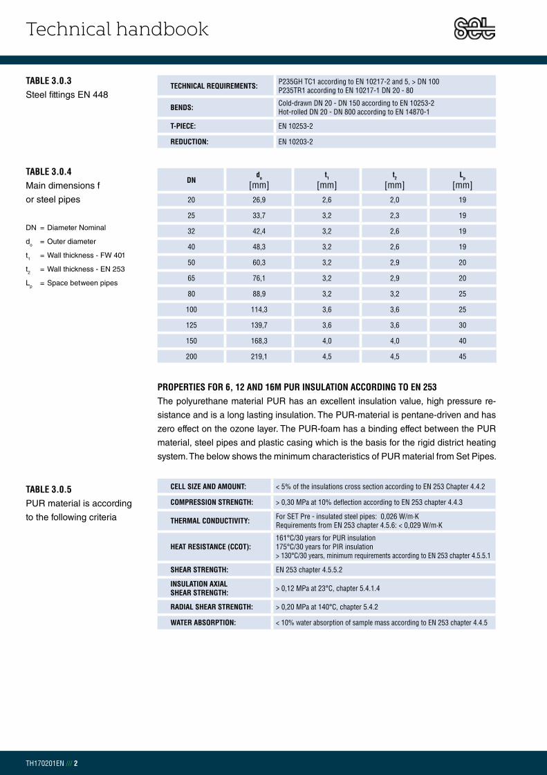
Technical handbook
TH170201EN /// 2
PROPERTIES FOR 6, 12 AND 16M PUR INSULATION ACCORDING TO EN 253The polyurethane material PUR has an excellent insulation value, high pressure re-
sistance and is a long lasting insulation. The PUR-material is pentane-driven and has
zero effect on the ozone layer. The PUR-foam has a binding effect between the PUR
material, steel pipes and plastic casing which is the basis for the rigid district heating
system. The below shows the minimum characteristics of PUR material from Set Pipes.
TABLE 3.0.4 Main dimensions f
or steel pipes
DN = Diameter Nominal
do = Outer diameter
t1 = Wall thickness - FW 401
t2 = Wall thickness - EN 253
Lp = Space between pipes
TABLE 3.0.5 PUR material is according
to the following criteria
DNdo
[mm]t1
[mm]t2
[mm]Lp
[mm]20 26,9 2,6 2,0 19
25 33,7 3,2 2,3 19
32 42,4 3,2 2,6 19
40 48,3 3,2 2,6 19
50 60,3 3,2 2,9 20
65 76,1 3,2 2,9 20
80 88,9 3,2 3,2 25
100 114,3 3,6 3,6 25
125 139,7 3,6 3,6 30
150 168,3 4,0 4,0 40
200 219,1 4,5 4,5 45
CELL SIZE AND AMOUNT: < 5% of the insulations cross section according to EN 253 Chapter 4.4.2
COMPRESSION STRENGTH: > 0,30 MPa at 10% deflection according to EN 253 chapter 4.4.3
THERMAL CONDUCTIVITY: For SET Pre - insulated steel pipes: 0,026 W/m·K Requirements from EN 253 chapter 4.5.6: < 0,029 W/m·K
HEAT RESISTANCE (CCOT):161°C/30 years for PUR insulation 175°C/30 years for PIR insulation> 130°C/30 years, minimum requirements according to EN 253 chapter 4.5.5.1
SHEAR STRENGTH: EN 253 chapter 4.5.5.2
INSULATION AXIAL SHEAR STRENGTH: > 0,12 MPa at 23°C, chapter 5.4.1.4
RADIAL SHEAR STRENGTH: > 0,20 MPa at 140°C, chapter 5.4.2
WATER ABSORPTION: < 10% water absorption of sample mass according to EN 253 chapter 4.4.5
TECHNICAL REQUIREMENTS: P235GH TC1 according to EN 10217-2 and 5, > DN 100 P235TR1 according to EN 10217-1 DN 20 - 80
BENDS: Cold-drawn DN 20 - DN 150 according to EN 10253-2 Hot-rolled DN 20 - DN 800 according to EN 14870-1
T-PIECE: EN 10253-2
REDUCTION: EN 10203-2
TABLE 3.0.3 Steel fittings EN 448

Technical handbook
TH170201EN /// 3
CASING PIPE ACCORDING TO EN 253The PE casing pipe is resilient, has a high chemical resistance to sunlight and is
therefore an optimal cover over PUR foam. The pipes are produced seamless and
are coated with corona treated polyethylene for maximum adhesion to the PUR foam.
Minimal requirements of wall thickness are according to EN 253.
Casing pipe material is according to the following criteria:
TABLE 3.0.6 PE Casing pipe
Specifications
MATERIAL: Polyethylene – PE100
COLOR: Carbon black > 2,5 % of the mass according to EN 253 Chapter 4.3.1.1
MATERIAL PROPERTIES: EN 253 Chapter 4.3.1.1
MINIMUM WALL THICKNESS: EN 253 Chapter 4.3.2.2 Table 5
THERMAL CONDUCTIVITY: 0,40 W/m·K
MELT FLOW INDEX: 0,20 - 1,4 g/10 min. according to EN 253 Chapter 4.3.1.2
Do [mm]
tmin[mm]
125 3,0
140 3,0
160 3,0
180 3,0
200 3,2
225 3,4
250 3,6
280 3,9
315 4,1
355 4,5
400 4,8
450 5,2
500 5,6
560 6,0
630 6,6
710 7,2
TABLE 3.0.7Main dimensions for
PE casing pipe
according to EN 253
Do = Outer diameter
tmin = Minimum wall thickness

Technical handbook
TH170201EN /// 4
PRODUCTION CONTROL OF PRE-INSULATION DOUBLE STEEL PIPE To ensure a high product quality the entire production from Set Pipes goes through
strict quality control. The quality control of pre-insulated double pipes are according to
EN 15698-1, table A.1. Further details regarding casing pipe, insulation foam and steel
pipe can be found in EN 253, Edition D.
The quality control of pre-insulated carrier pipes is according to EN 253
standard for district heating pipes. Furthermore, additional tests are carried out and
documented. Highly qualified employees and their awareness of quality is our strength
in manufacturing.
PRODUCTION CONTROL OF STEEL FOR PRE-INSULATED FITTINGS The quality control of steel part for pre-insulated fittings is according to EN 448
standard. A pre-determine percentage of fittings go through radiographic
examination. All fittings are visually inspected and pressure tested.
PRODUCTION CONTROL OF INSULATED FITTINGS The control of pre-insulated fittings is according to EN 448 standard. Set Pipes uses
up to 40% increased wall thickness in the casing pipe production to ensure greater
strength in pre-insulated fittings.
Do [mm]
t[mm]
tmin[mm]
90 4,0 3,0
110 4,0 3,0
125 4,5 3,0
140 5,0 3,0
160 5,0 3,0
180 5,5 3,0
200 5,5 3,2
225 6,0 3,4
250 6,0 3,6
280 6,0 3,9
315 6,3 4,1
TABLE 3.0.8Casing pipe for fittings
Do = Outer diameter of the Casing pipe
t = Casing pipe wall thickness
according to Set Pipes
tmin = Casing pipe wall thickness
according to E253

Technical handbook
TH170201EN /// 5
EXAMPLE: A house has the thermal requirement of 14 kW and temperature change between flow and return pipelines is 40°C. If we estimate the specific heat and density for 70°C water then we can find the water demand for the house:
HEAT DEMANDTo define the pipe dimension of the district heating system the following must be
taken into consideration, heating, drinking water, snow melting and other uses.
The pipe diameter is determined by the sum of the previously mentioned usage.
In the case of heating the following equation can be used:
THUS: = Mass flow [m3/s]
Q = Thermal requirement [W]
w = Water density (978 kg/m3 við 70°C)
cp = Specific heat for water (4191 J/kg·K við 70°C)
ΔT = Temperature change between flow and return pipelines (TVL – TRL) [K]
TOTAL PRESSURE DROP FOR PRE – INSULATED DOUBLE STEEL PIPES After the water demand has been determined it is possible to calculate the pressure
loss for a selected pipe dimension. Network length, height difference, the number
of connections, and branches have an influence on the pressure loss. The pressure
loss in pipes should be in the range of 100 – 200 Pa/m for DN < 150, and 100 – 150
Pa/m for DN ≥ 150. Pressure loss requirements can vary depending on the system,
for example a system with a high pressure can lead to increased operating costs.
To calculate the pressure loss for each pipe dimension the following equation can
be used:
CHAPTER 3.1APPLICATION DESIGN
CHAPTER 3.1.1PRESSURE DROP
THUS: f = Friction factor [-]
L = Length of the pipe [m]
di = Inner diameter of the steel pipe [m]
V = Average water velocity [m/s]
w = Water density (972 kg/m3 at 80°C)
Hm = Height difference [m]
g = Acceleration due to gravity
Pipe

Technical handbook
TH170201EN /// 6
The friction factor is found with the following equation:
THUS:k = Resistance Coefficients for steel = 0,10 mm
Re = Reynolds number for flow in a circular pipe
The friction factor can also be found roughly with the Moody chart which can be
seen in graph 2.1.1. However, to find this factor it is necessary to know what kind of
flow is in the pipeline. The type of flow is determined with the Reynolds number (Re)
equation:
THUS: = Kinematic viscosity for water (0,366 x 10-6 m2/s at 80°C)
Reynolds number < 2300 forms a laminar flow which is smooth, steady and
therefore low pressure loss in the pipe. If the Reynolds number > 4000 then the
flow will be turbulent which is fluctuating and agitated vortex that leads to increased
pressure loss in the pipe. Higher Reynolds number leads to stronger vortex,
therefore greater pressure drop and more danger of cavitation forming in the pipe
and fittings. Between 2300 – 4000 forms a transition to turbulence flow.
Graph 3.1.1.2 shows pressure loss in a single flow pipe taking into consideration
water need, pipe dimension, and average water velocity. Also there is an example
on how to use the graph.

Technical handbook
TH170201EN /// 7
GRAPH 3.1.1.1 - MOODY GRAPH
103
104
105
106
107
108
10−2
10−1 89
1.2
1.4
1.6
1.82
2.53
3.54
4.55
5.56789
67
82
34
56
78
23
45
67
82
34
56
78
23
45
67
82
34
56
78
1e−0
05
2e−0
05
5e−0
05
0.00
01
0.00
02
0.00
04
0.00
06
0.00
080.
001
0.00
15
0.00
2
0.00
3
0.00
4
0.00
6
0.00
8
0.01
0.01
250.
015
0.01
750.
02
0.02
5
0.03
0.03
5
0.04
0.04
50.
05
0.06
0.07
Lam
inar
flow
Crit
ical
zone
Tra
nsiti
on z
one
Com
plet
e tu
rbul
ence
, rou
gh p
ipes
, R >
350
0/r,
1/√
f =
1.14
− 2
log
r
Darcy−Weisbach friction factor f
Mo
od
y D
iag
ram
Mat
eria
l
Riv
eted
ste
elC
oncr
ete
Woo
d st
ave
Cas
t iro
nG
alva
nize
d iro
nA
spha
lted
cast
iron
Com
mer
cial
ste
elD
raw
n tu
bing
Rey
nold
s nu
mbe
rR
(V
in m
/s, D
in m
, ν in
m 2/s
)V
D ν
Relative roughness r (ε in mm, D in mm)εD
VD
for w
ater
at 2
0°C
(V
in m
/s, D
in c
m)
0.06 |
|0.
1 |0.
2 |0.
4 |0.
6 |0.
8 |1 |
2 |4 |
6 |8 |
10 |20 |
40 |60 |
|10
0 |20
0 |40
0 |60
0 ||
1000 |
2000 |
4000 |
6000 |
|10
000
|__
____
____
____
____
____
____
____
____
____
____
____
____
____
____
____
____
____
____
____
____
____
____
____
____
____
____
____
____
____
____
____
____
____
____
____
____
____
____
____
____
____
____
____
____
____
____
____
____
__
VD
for a
tmos
pher
ic a
ir at
20°
C1 |
2 |4 |
6 |8 |
10 |20 |
40 |60 |
|10
0 |20
0 |40
0 |60
0 ||
1000 |
2000 |
4000 |
6000 |
|10
000
|20
000
|40
000
|60
000
||10
0000
|
ε (m
m)
0.9−
90.
3−3
0.18
−0.9
0.25
0.15
0.12
0.04
60.
0015
Flui
d at
20°
C
Wat
erAi
r (10
1.32
5 kP
a)
ν (m
2 /s)
1.00
3e−0
061.
511e
−005
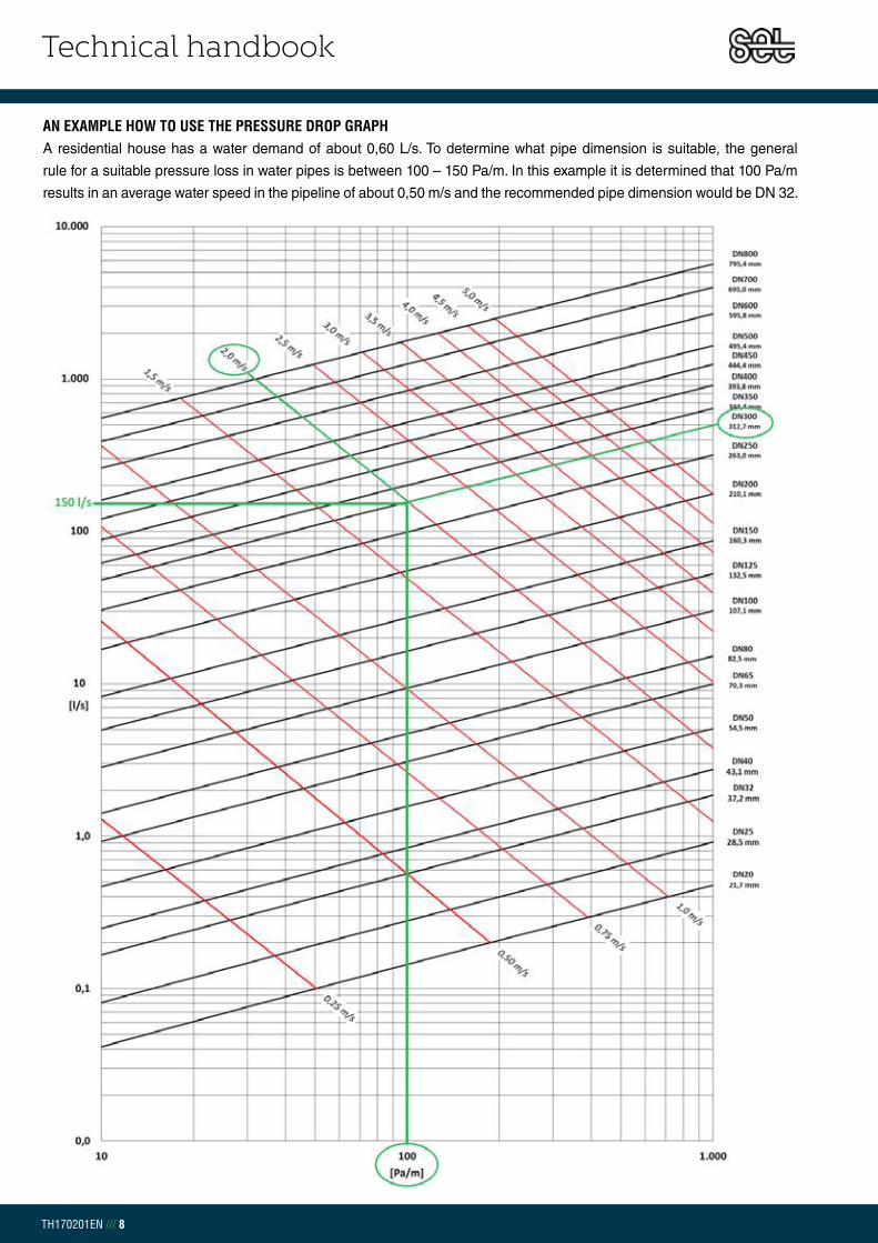
Technical handbook
TH170201EN /// 8
AN EXAMPLE HOW TO USE THE PRESSURE DROP GRAPHA residential house has a water demand of about 0,60 L/s. To determine what pipe dimension is suitable, the general
rule for a suitable pressure loss in water pipes is between 100 – 150 Pa/m. In this example it is determined that 100 Pa/m
results in an average water speed in the pipeline of about 0,50 m/s and the recommended pipe dimension would be DN 32.
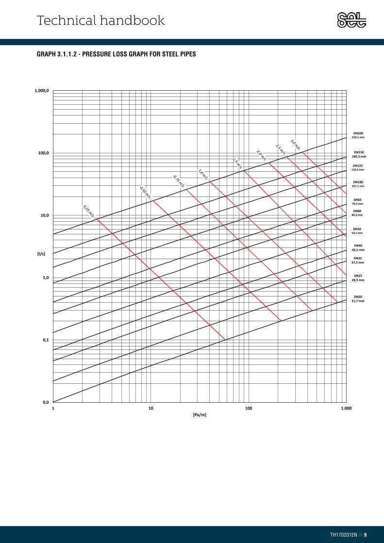
Technical handbook
TH170201EN /// 9
GRAPH 3.1.1.2 - PRESSURE LOSS GRAPH FOR STEEL PIPES
DN2021,7 mm
DN2528,5 mm
DN3237,2 mm
DN4043,1 mm
DN5054,5 mm
DN6570,3 mm
DN8082,5 mm
DN100107,1 mm
DN125132,5 mm
DN150160,3 mm
DN200210,1 mm
0,0
0,1
1,0
10,0
100,0
1.000,0
1 10 100 1.000
[l/s]
[Pa/m]

Technical handbook
TH170201EN /// 10
EXPANSION – PRE-INSULATED DOUBLE STEEL PIPESThe pre-insulated material from Set Pipes is a rigid system consisting of medium
pipe, PUR-foam and a casing pipe, meaning a continuous connection between the
steel pipes, PUR-foam and casing pipe. All three components of the pipe expand
or shortens evenly depending on cold or warm water running through the pipe.
Forces working against expansion due to temperature changes Fa are soil weight
force and weight of pipe with water. Together these friction forces form the F force.
These calculations, as with other calculations in this book are based on EN 13941
standard. However, standard EN 13941 does not address double pipes. Therefore,
the following is based on the same with higher security.
FREE EXPANSION With a flow and return pipeline in the same casing pipe a different expansions force
can be found in the cross section of the pipe. Lmax for double pipe is calculated in
tables 3.1.2.1, 3.1.2.2 og 3.1.2.3.
TABLE 3.1.2.1Maximum length between
expansions for double pipe [m]
insulation series 1
DN = Diameter Nominal
do = Outer diameter of the steel pipe
t1 = Wall thickness of the steel pipe
Do = Outer diameter of the Casing pipe
t2 = Wall thickness of the casing pipe
Steel pipe Casing pipe Depth of the pipe
DN do[mm]
t1[mm]
Do[mm]
t2[mm] 0,60 m 0,80 m 1,0 m 1,2 m
20 26,9 2,3 125 3,0 40,1 30,9 25,1 21,2
25 33,7 2,6 140 3,0 50,4 39,0 31,8 26,8
32 42,4 2,6 160 3,0 55,5 43,1 35,2 29,8
40 48,3 2,6 160 3,0 63,5 49,4 40,4 34,1
50 60,3 2,9 200 3,2 69,0 54,0 44,3 37,6
65 76,1 2,9 225 3,4 76,4 60,1 49,5 42,1
80 88,9 3,2 250 3,6 86,9 68,7 56,7 48,3
100 114,3 3,6 315 4,1 95,4 76,1 63,3 54,2
125 139,7 3,6 400 4,8 87,2 70,4 59,0 50,8
150 168,3 4,0 450 5,2 100,1 81,4 68,5 59,2
200 219,1 4,5 560 6,0 109,7 90,4 76,9 66,9
CHAPTER 3.1.2EXPANSION

Technical handbook
TH170201EN /// 11
TABLE 3.1.2.2Maximum length between
expansions for double pipe [m]
insulation series 2
DN = Diameter Nominal
do = Outer diameter of the steel pipe
t1 = Wall thickness of the steel pipe
Do = Outer diameter of the Casing pipe
t2 = Wall thickness of the casing pipe
Steel pipe Casing pipe Depth of the pipe
DN do[mm]
t1[mm]
Do[mm]
t2[mm] 0,60 m 0,80 m 1,0 m 1,2 m
20 26,9 2,3 140 3,0 30,5 23,6 19,2 16,2
25 33,7 2,6 160 3,0 37,5 29,1 23,8 20,1
32 42,4 2,6 180 3,0 42,0 32,7 26,7 22,6
40 48,3 2,6 180 3,0 48,1 37,5 30,7 26,0
50 60,3 2,9 225 3,4 52,1 40,9 33,6 28,6
65 76,1 2,9 250 3,6 58,6 46,2 38,1 32,4
80 88,9 3,2 280 3,9 66,0 52,3 43,3 36,9
100 114,3 3,6 355 4,5 71,7 57,4 47,9 41,0
125 139,7 3,6 450 5,2 65,5 53,0 44,6 38,4
150 168,3 4,0 500 5,6 76,3 62,2 52,5 45,4
200 219,1 4,5 630 6,6 82,3 68,0 58,0 50,5
TABLE 3.1.2.3Maximum length between
expansions for double pipe [m]
insulation series 3
DN = Diameter Nominal
do = Outer diameter of the steel pipe
t1 = Wall thickness of the steel pipe
Do = Outer diameter of the Casing pipe
t2 = Wall thickness of the casing pipe
Steel pipe Casing pipe Depth of the pipe
DN do[mm]
t1[mm]
Do[mm]
t2[mm] 0,60 m 0,80 m 1,0 m 1,2 m
20 26,9 2,3 160 3,0 26,3 20,4 16,7 14,1
25 33,7 2,6 180 3,0 32,9 25,6 20,9 17,7
32 42,4 2,6 200 3,2 37,3 29,1 23,9 20,2
40 48,3 2,6 200 3,2 42,7 33,4 27,4 23,2
50 60,3 2,9 250 3,6 46,1 36,3 29,9 25,5
65 76,1 2,9 280 3,9 51,3 40,6 33,6 28,6
80 88,9 3,2 315 4,1 57,4 45,7 37,9 32,4
100 114,3 3,6 400 4,8 62,0 49,9 41,7 35,9
125 139,7 3,6 500 5,6 57,3 46,7 39,4 34,0
150 168,3 4,0 560 6,0 66,0 54,1 45,9 39,8
200 219,1 4,5 710 7,2 70,2 58,4 50,0 43,8

Technical handbook
TH170201EN /// 12
FIG 3.1.3.1Cross section of double pipe
CHAPTER 3.1.3HEAT LOSS
HEAT LOSS - PRE-INSULATED DOUBLE STEEL PIPES One of the most important characteristics of district heating systems is their heat
retention. As most district heating stations in Europe have to burn gas, oil, biomass
or waste, good insulation and proper ground work is necessary. Set Pipes works
continuously to improve foam insulation in close cooperation with its suppliers to help
improve energy efficiency and reduce CO2 emission.
All results in the tables are calculated by Set Pipes technical department.
Calculations for heat loss in double pipes is more complicated and are based on a
FEM method together with traditional methods as described in chapter 2.
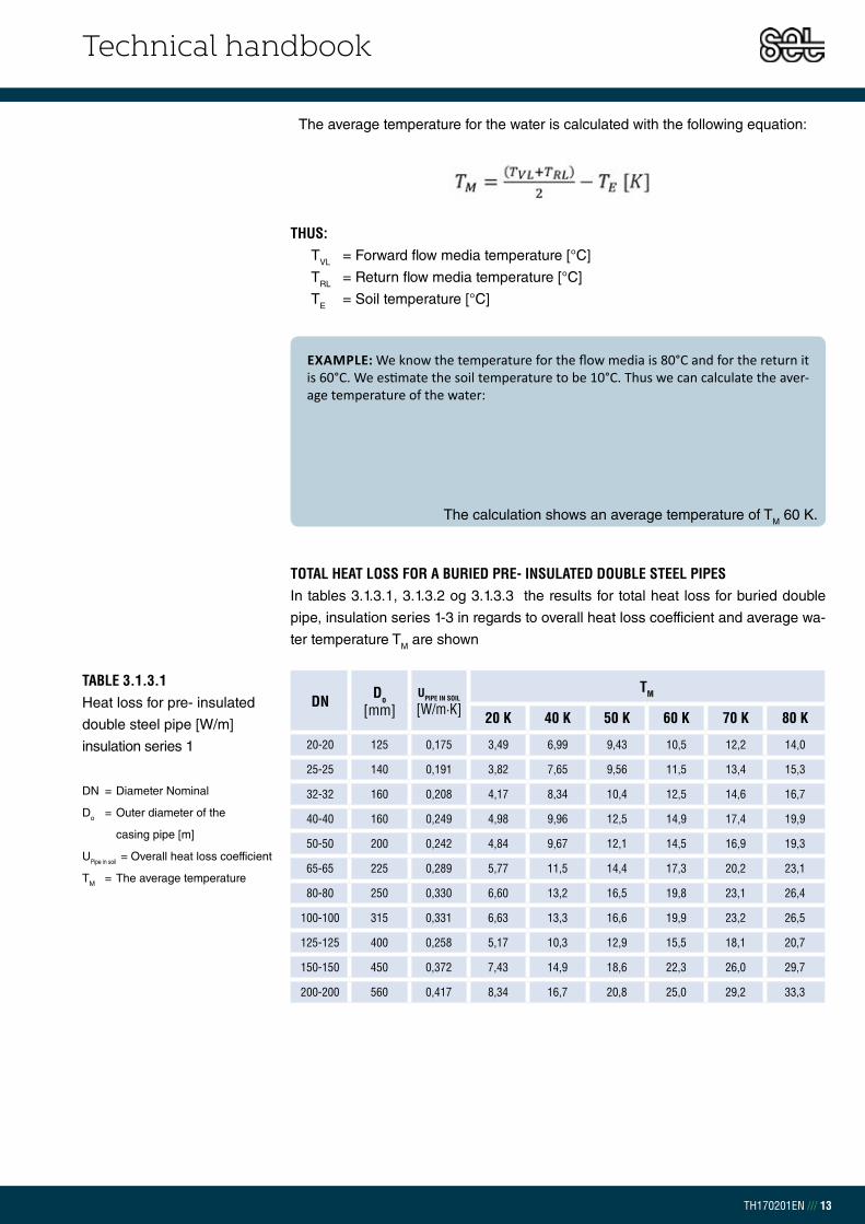
Technical handbook
TH170201EN /// 13
TOTAL HEAT LOSS FOR A BURIED PRE- INSULATED DOUBLE STEEL PIPESIn tables 3.1.3.1, 3.1.3.2 og 3.1.3.3 the results for total heat loss for buried double
pipe, insulation series 1-3 in regards to overall heat loss coefficient and average wa-
ter temperature TM are shown
TABLE 3.1.3.1 Heat loss for pre- insulated
double steel pipe [W/m]
insulation series 1
DN = Diameter Nominal
Do = Outer diameter of the
casing pipe [m]
UPipe in soil = Overall heat loss coefficient
TM = The average temperature
DN Do[mm]
UPIPE IN SOIL
[W/m·K] TM
20 K 40 K 50 K 60 K 70 K 80 K
20-20 125 0,175 3,49 6,99 9,43 10,5 12,2 14,0
25-25 140 0,191 3,82 7,65 9,56 11,5 13,4 15,3
32-32 160 0,208 4,17 8,34 10,4 12,5 14,6 16,7
40-40 160 0,249 4,98 9,96 12,5 14,9 17,4 19,9
50-50 200 0,242 4,84 9,67 12,1 14,5 16,9 19,3
65-65 225 0,289 5,77 11,5 14,4 17,3 20,2 23,1
80-80 250 0,330 6,60 13,2 16,5 19,8 23,1 26,4
100-100 315 0,331 6,63 13,3 16,6 19,9 23,2 26,5
125-125 400 0,258 5,17 10,3 12,9 15,5 18,1 20,7
150-150 450 0,372 7,43 14,9 18,6 22,3 26,0 29,7
200-200 560 0,417 8,34 16,7 20,8 25,0 29,2 33,3
The average temperature for the water is calculated with the following equation:
THUS:TVL = Forward flow media temperature [°C]
TRL = Return flow media temperature [°C]
TE = Soil temperature [°C]
EXAMPLE: We know the temperature for the flow media is 80°C and for the return it is 60°C. We estimate the soil temperature to be 10°C. Thus we can calculate the aver-age temperature of the water:
The calculation shows an average temperature of TM 60 K.

Technical handbook
TH170201EN /// 14
TABLE 3.1.3.3 Heat loss for pre-insulated
double steel pipe [W/m]
insulation series 3
DN = Diameter Nominal
Do = Outer diameter of the
casing pipe [m]
UPipe in soil = Overall heat loss coefficient
TM = The average temperature
DN Do[mm]
UPIPE IN SOIL
[W/m·K] TM
20 K 40 K 50 K 60 K 70 K 80 K
20-20 160 0,138 2,75 5,50 6,88 8,25 9,63 11,0
25-25 180 0,147 2,93 5,87 7,34 8,80 10,3 11,7
32-32 200 0,161 3,21 6,43 8,04 9,64 11,2 12,9
40-40 200 0,182 3,64 7,29 9,11 10,9 12,7 14,6
50-50 250 0,179 3,58 7,15 8,94 10,7 12,5 14,3
65-65 280 0,202 4,04 8,09 10,1 12,1 14,2 16,2
80-80 315 0,215 4,31 8,61 10,8 12,9 15,1 17,2
100-100 400 0,214 4,28 8,56 10,7 12,8 15,0 17,1
125-125 500 0,208 4,16 8,32 10,4 12,5 14,6 16,6
150-150 560 0,235 4,70 9,39 11,7 14,1 16,4 18,8
200-200 710 0,242 4,84 9,68 12,1 14,5 16,9 19,4
TABLE 3.1.3.2 Heat loss for pre-insulated
double steel pipe [W/m]
insulation series 2
DN = Diameter Nominal
Do = Outer diameter of the
casing pipe [m]
UPipe in soil = Overall heat loss coefficient
TM = The average temperature
DN Do[mm]
UPIPE IN SOIL
[W/m·K] TM
20 K 40 K 50 K 60 K 70 K 80 K
20-20 140 0,155 3,10 6,21 7,76 9,31 10,9 12,4
25-25 160 0,164 3,29 6,58 8,22 9,86 11,5 13,2
32-32 180 0,180 3,60 7,20 8,99 10,8 12,6 14,4
40-40 180 0,208 4,16 8,32 10,4 12,5 14,6 16,6
50-50 225 0,203 4,07 8,13 10,2 12,2 14,2 16,3
65-65 250 0,238 4,76 9,53 11,9 14,3 16,7 19,1
80-80 280 0,260 5,19 10,4 13,0 15,6 18,2 20,8
100-100 355 0,258 5,16 10,3 12,9 15,5 18,1 20,6
125-125 450 0,243 4,86 9,7 12,2 14,6 17,0 19,5
150-150 500 0,287 5,75 11,5 14,4 17,2 20,1 23,0
200-200 630 0,303 6,06 12,1 15,1 18,2 21,2 24,2

Technical handbook
TH170201EN /// 15
PRE-INSULATED DOUBLE STEEL PIPES AND FITTINGS Pre-insulated steel pipes and fittings are usually transported and delivered by truck.
Make sure that the truck has good access to the destination with 12 m lengths or
16 m if applicable. Pipes and fittings are sealed with protective plastic end caps on
the steel and must remain in place until assembly. All joint material as well as
accessories are delivered in plastic packaging. Do not remove packaging before
installation. The customer is responsible for the unloading of goods. Preparation of a
flat and a dry unloading area is required for safe unloading, making sure nothing can
damage the casing pipe. Pre-insulated steel pipes from Set Pipes are delivered in bundles
up to 280 casing according to table below or loose according to customer requests.
LOADING During loading and unloading regulations
must be followed to minimize the risk of
accidents. Ensure no one is nearby, and the
loading operator should be located at a safe
distance.
All equipment used for loading must
be certificated, with a CE label and a
specified maximum weight capacity. Use
only flat nylon web belts wider than 100 mm
during loading. Do not use chains, ropes, wires or other lifting equipment. When
loading of larger pipes, 12 m and 16 m it is necessary to use a support bar between
belts (see photo 2.2.1). The support bar to be at least 4 m long. Do not allow pipes
or fittings to drop down from the vehicle. Casing pipe is sensitive to sharp edges and
heavy force. Ensure casing pipe is undamaged to avoid further damage to pipes
once in use.
CHAPTER 3.2TRANSPORT AND STORAGE
TABLE 3.2.1 Weight and number
of pipes in bundle
FIG 3.2.1UNLOADING WITH SLINGS Use wide nylon web slings
while unloading and for
further handling. Ropes,
chains or other lifting
equipment are prohibited.
CASING PIPE LENGTHS
OUTER DIAMETER [mm]
6 M [pc]
WEIGHT [KG] Series 1
12 M [pc]
WEIGHT [KG] Series 1
125 26 868 26 1737
140 23 851 23 1702
160 20 930 20 1860
200 14 1005 14 2010
225 9 811 9 1622
250 7 799 7 1599

Technical handbook
TH170201EN /// 16
STACK Pipes shall be stacked placing wooden strips with a minimum width of 140 mm
between or laid on a stone free, flat and dry sand surface. Space between
wooden strips shall be no more than 2 m. Stacking shall be done so the bottom layer
is supported and free from water with a maximum stacking height of 2 m. Ensure the
pressure strength does not exceed 0,3 N/mm2 (3 kg/cm2).
FIG 3.2.2STACKS WITH WOODEN SPACING STRIPSStack pipes so the max.
pressure does not exceed be
<0,3 N/mm2 (3 kg /cm2)
FIG 3.2.3 BENDS AND T-PIECES Allow insulation surface
to lean downward
FITTINGS Fittings shall be stored so the insulation surface leans downward and is free from
any water.
If pipes or fittings are stored outside for longer periods of time ensure protection
against corrosion.
PUR INSULATION AND JOINT MATERIALStore shrink tubes, sleeves, expansion pads and other accessories where they are
protected from cold weather and direct sunlight. Liquid insulation components in
barrels, bottles or bags must be stored in a secured area at a temperature between
+10 and +20°C. Insulation material Poly (light colored) and Isocyanate (dark colored)
may under no circumstances freeze or reach a temperature below 0°c during use or
storage or the foam will crystallize and no longer possible to use.
14 cm
Max 2,0m
Max 2,0m
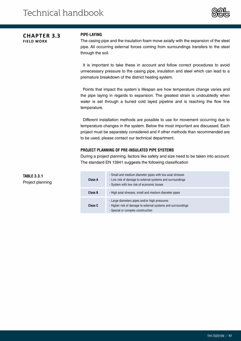
Technical handbook
TH170201EN /// 17
PIPE-LAYING The casing pipe and the insulation foam move axially with the expansion of the steel
pipe. All occurring external forces coming from surroundings transfers to the steel
through the soil.
It is important to take these in account and follow correct procedures to avoid
unnecessary pressure to the casing pipe, insulation and steel which can lead to a
premature breakdown of the district heating system.
Points that impact the system´s lifespan are how temperature change varies and
the pipe laying in regards to expansion. The greatest strain is undoubtedly when
water is set through a buried cold layed pipeline and is reaching the flow line
temperature.
Different installation methods are possible to use for movement occurring due to
temperature changes in the system. Below the most important are discussed. Each
project must be separately considered and if other methods than recommended are
to be used, please contact our technical department.
PROJECT PLANNING OF PRE-INSULATED PIPE SYSTEMS During a project planning, factors like safety and size need to be taken into account.
The standard EN 13941 suggests the following classification
CHAPTER 3.3FIELD WORK
TABLE 3.3.1 Project planning
Class A- Small and medium diameter pipes with low axial stresses- Low risk of damage to external systems and surroundings- System with low risk of economic losses
Class B - High axial stresses, small and medium diameter pipes
Class C- Large diameters pipes and/or high pressures- Higher risk of damage to external systems and surroundings- Special or complex construction

Technical handbook
TH170201EN /// 18
With this installation technique it is possible to lay the pipeline directly in the trench
and put into operation. This technique may only be used if the longest length <Lmax
is followed. If the laying length is longer than Lmax a Z or U compensator for the
expansion is necessary. This method can be used where the forward flow media
temperature is <85°C. Expansion foam pads on bends are needed in order to absorb
movement.
FIG 3.3.1.1U and Z compensators
EXPANSION FACTORS The standard recommends that calculated are four parameters to find an effective
system. The parameters are:
1. Factors due to internal pressure.
2. Factors due to repetitive strain.
3. Factors that can lead to instability or deformation.
4. Deformation or settlements that may affect the piping system,
external systems or structures
More detailed description can be found in the EN 13941 standard.
A
x x
A
A
x
x
d
D
NAME
DEBUR AND
EDGES
FINISH:
ANGULAR:
Q.A
MFG
APPV'D
CHK'D
Expansion loopWEIGHT:
A3
SHEET 1 OF 1SCALE:1:50
SIGNATURE DATE TITLE:
REVISIONBREAK SHARP
DWG NO.MATERIAL:
DO NOT SCALE DRAWINGUNLESS OTHERWISE SPECIFIED:DIMENSIONS ARE IN MILLIMETERS
SURFACE FINISH:
TOLERANCES:
LINEAR:
DRAWN
D d
A
x x
A
A
x
x
d
D
NAME
DEBUR AND
EDGES
FINISH:
ANGULAR:
Q.A
MFG
APPV'D
CHK'D
Expansion loopWEIGHT:
A3
SHEET 1 OF 1SCALE:1:50
SIGNATURE DATE TITLE:
REVISIONBREAK SHARP
DWG NO.MATERIAL:
DO NOT SCALE DRAWINGUNLESS OTHERWISE SPECIFIED:DIMENSIONS ARE IN MILLIMETERS
SURFACE FINISH:
TOLERANCES:
LINEAR:
DRAWN
D d
CHAPTER 3.3.1COLD LAYING WITH U AND Z COMPENSATORS
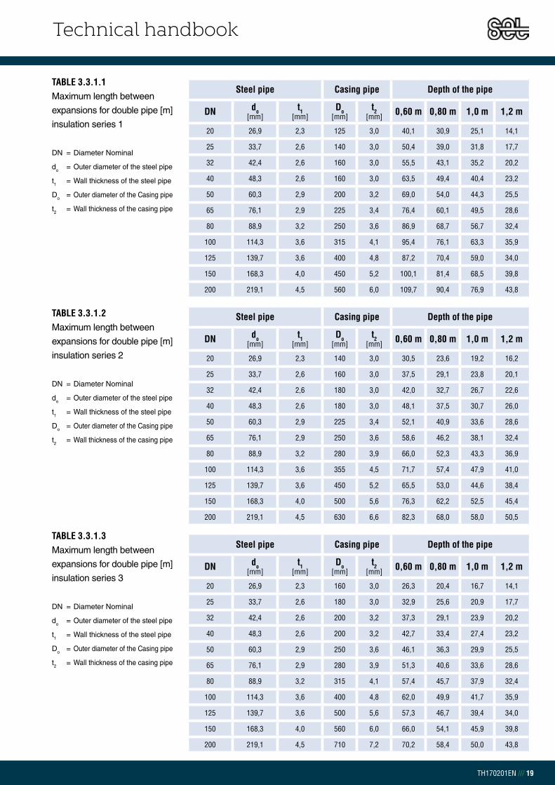
Technical handbook
TH170201EN /// 19
TABLE 3.3.1.2Maximum length between
expansions for double pipe [m]
insulation series 2
DN = Diameter Nominal
do = Outer diameter of the steel pipe
t1 = Wall thickness of the steel pipe
Do = Outer diameter of the Casing pipe
t2 = Wall thickness of the casing pipe
Steel pipe Casing pipe Depth of the pipe
DN do[mm]
t1[mm]
Do[mm]
t2[mm] 0,60 m 0,80 m 1,0 m 1,2 m
20 26,9 2,3 140 3,0 30,5 23,6 19,2 16,2
25 33,7 2,6 160 3,0 37,5 29,1 23,8 20,1
32 42,4 2,6 180 3,0 42,0 32,7 26,7 22,6
40 48,3 2,6 180 3,0 48,1 37,5 30,7 26,0
50 60,3 2,9 225 3,4 52,1 40,9 33,6 28,6
65 76,1 2,9 250 3,6 58,6 46,2 38,1 32,4
80 88,9 3,2 280 3,9 66,0 52,3 43,3 36,9
100 114,3 3,6 355 4,5 71,7 57,4 47,9 41,0
125 139,7 3,6 450 5,2 65,5 53,0 44,6 38,4
150 168,3 4,0 500 5,6 76,3 62,2 52,5 45,4
200 219,1 4,5 630 6,6 82,3 68,0 58,0 50,5
TABLE 3.3.1.3Maximum length between
expansions for double pipe [m]
insulation series 3
DN = Diameter Nominal
do = Outer diameter of the steel pipe
t1 = Wall thickness of the steel pipe
Do = Outer diameter of the Casing pipe
t2 = Wall thickness of the casing pipe
Steel pipe Casing pipe Depth of the pipe
DN do[mm]
t1[mm]
Do[mm]
t2[mm] 0,60 m 0,80 m 1,0 m 1,2 m
20 26,9 2,3 160 3,0 26,3 20,4 16,7 14,1
25 33,7 2,6 180 3,0 32,9 25,6 20,9 17,7
32 42,4 2,6 200 3,2 37,3 29,1 23,9 20,2
40 48,3 2,6 200 3,2 42,7 33,4 27,4 23,2
50 60,3 2,9 250 3,6 46,1 36,3 29,9 25,5
65 76,1 2,9 280 3,9 51,3 40,6 33,6 28,6
80 88,9 3,2 315 4,1 57,4 45,7 37,9 32,4
100 114,3 3,6 400 4,8 62,0 49,9 41,7 35,9
125 139,7 3,6 500 5,6 57,3 46,7 39,4 34,0
150 168,3 4,0 560 6,0 66,0 54,1 45,9 39,8
200 219,1 4,5 710 7,2 70,2 58,4 50,0 43,8
TABLE 3.3.1.1Maximum length between
expansions for double pipe [m]
insulation series 1
DN = Diameter Nominal
do = Outer diameter of the steel pipe
t1 = Wall thickness of the steel pipe
Do = Outer diameter of the Casing pipe
t2 = Wall thickness of the casing pipe
Steel pipe Casing pipe Depth of the pipe
DN do[mm]
t1[mm]
Do[mm]
t2[mm] 0,60 m 0,80 m 1,0 m 1,2 m
20 26,9 2,3 125 3,0 40,1 30,9 25,1 14,1
25 33,7 2,6 140 3,0 50,4 39,0 31,8 17,7
32 42,4 2,6 160 3,0 55,5 43,1 35,2 20,2
40 48,3 2,6 160 3,0 63,5 49,4 40,4 23,2
50 60,3 2,9 200 3,2 69,0 54,0 44,3 25,5
65 76,1 2,9 225 3,4 76,4 60,1 49,5 28,6
80 88,9 3,2 250 3,6 86,9 68,7 56,7 32,4
100 114,3 3,6 315 4,1 95,4 76,1 63,3 35,9
125 139,7 3,6 400 4,8 87,2 70,4 59,0 34,0
150 168,3 4,0 450 5,2 100,1 81,4 68,5 39,8
200 219,1 4,5 560 6,0 109,7 90,4 76,9 43,8

Technical handbook
TH170201EN /// 20
EXPANSION FOAM PADSIn order to absorb expansion movements of the pipe system in bends, branches and
compensators, the right size of expansion pads must be used around the casing
pipe. Set Pipes expansion pads are manufactured from cross-linked closed-cell poly-
ethylene and have no water or chemical absorption. The pads are corrugated. Once
the pads are placed around the pipe a thin laminated wrap around is placed over to
protect from sand and soil.
The expansion foam pads are delivered in dimension 1000 x 2000 x 40 mm. The
foam pad thickness tells how much movement can be absorbed. Each pad is 40 mm
thick and can absorb 35 mm, it is possible to put together up to three pads which can
absorb up to 105 mm
The laminated wrap around has a width of 1000 mm and 5 mm thick, each roll is
154m long.
Cutting size of expansion foam pad is according to table 3.3.2.1.
CHAPTER 3.3.2EXPANSION FOAM PADS

Technical handbook
TH170201EN /// 21
TABLE 3.3.2.1 Expansion foam pad cutting
Do = Outer diameter of the
casing pipe [mm]
Y = Number of strips pcs.
b = Width [mm]
S = Size no.
Do[mm]
Ypc.
b[mm]
Snr.
125 2 120 1
140 2 120 1
160 2 120 1
180 4 240 2
200 4 240 2
225 4 240 2
250 4 240 2
280 4 240 2
315 6 360 3
355 6 360 3
400 8 480 4
450 8 480 4
500 8 480 4
560 10 600 5
630 12 720 6
710 14 840 7
Please contact Set Pipes technical department to determine the necessary width
of the foam pad needed.
FIXING PLATES To ensure the pipeline absorbs all thermal expansion it is necessary to use
fixing plates on all joints unless using fittings such as bends or T pieces. The
minimum length between fixing plates is the pipe length, 12m or 16 m. All fittings
have fixing plates included and therefore reinforced joints. If the fixing plates need to
be welded less than 25 mm from foam it is necessary to remove foam until the
minimum distance of 25 mm is reached.
FIG 3.3.2.1Installation of expansion
foam pads
CHAPTER 3.3.3FIXING PLATES

Technical handbook
TH170201EN /// 22
PIPEDN
DISTANCE BETWEEN PIPES
Lp [mm]
PLATE WELD SIZE (WS)[mm]
H[mm]
B[mm]
t[mm]
20 19 45,9 50 4 2,8
25 19 52,7 50 4 2,8
32 19 61,4 50 4 2,8
40 19 67,3 60 4 2,8
50 20 80,3 70 5 3,5
65 20 96,1 100 5 3,5
80 25 113,9 100 6 4,2
100 25 139,3 120 6 4,2
125 30 169,7 150 6 4,2
150 40 208,3 200 6 4,2
200 45 264,1 250 8 5,7
TABLE 3.3.3.1Dimensions of fixing plates
FIG 3.3.3.1Fixing plates for double pipes
B
H
Min 25mm
TITLE:
DO NOT SCALE DRAWING
LINEAR:
ANGULAR:
FINISH:
TOLERANCES:
EDGES
NAME SIGNATURE DATE
UNLESS OTHERWISE SPECIFIED:
DIMENSIONS ARE IN MILLIMETERS
SURFACE FINISH:
DEBURR AND
BREAK SHARP
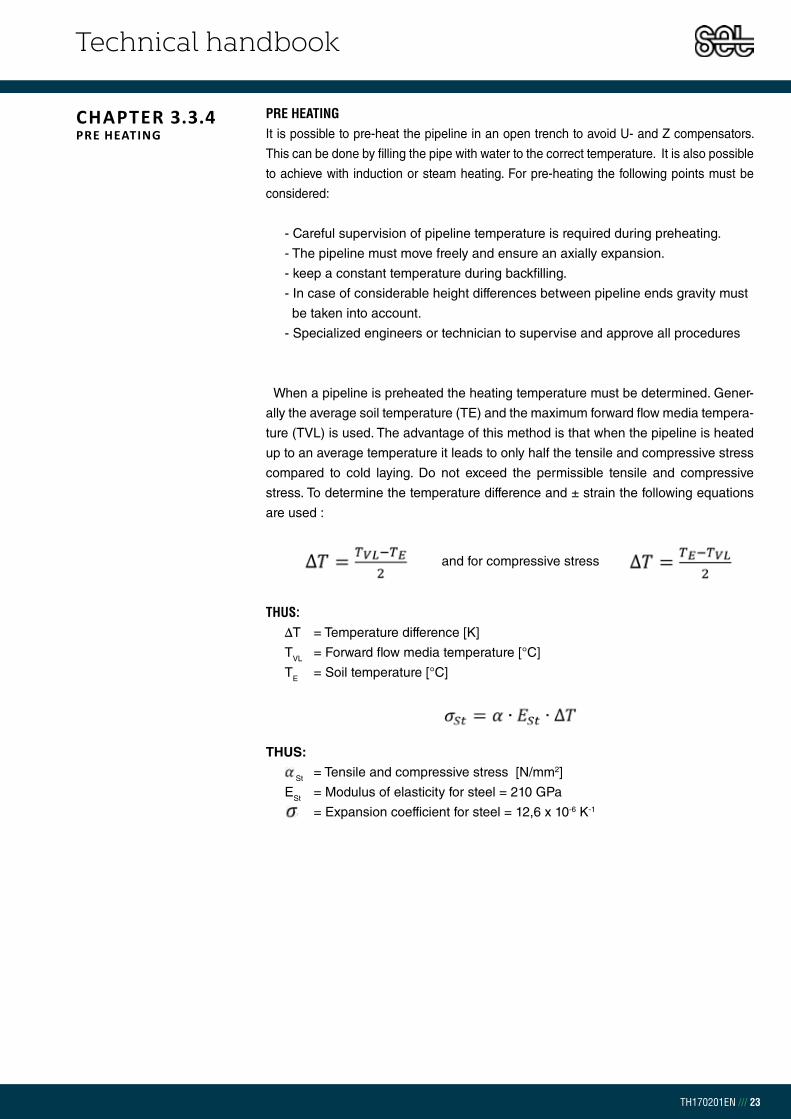
Technical handbook
TH170201EN /// 23
PRE HEATING It is possible to pre-heat the pipeline in an open trench to avoid U- and Z compensators.
This can be done by filling the pipe with water to the correct temperature. It is also possible
to achieve with induction or steam heating. For pre-heating the following points must be
considered:
- Careful supervision of pipeline temperature is required during preheating.
- The pipeline must move freely and ensure an axially expansion.
- keep a constant temperature during backfilling.
- In case of considerable height differences between pipeline ends gravity must
be taken into account.
- Specialized engineers or technician to supervise and approve all procedures
and for compressive stress
When a pipeline is preheated the heating temperature must be determined. Gener-
ally the average soil temperature (TE) and the maximum forward flow media tempera-
ture (TVL) is used. The advantage of this method is that when the pipeline is heated
up to an average temperature it leads to only half the tensile and compressive stress
compared to cold laying. Do not exceed the permissible tensile and compressive
stress. To determine the temperature difference and ± strain the following equations
are used :
THUS:ΔT = Temperature difference [K]
TVL = Forward flow media temperature [°C]
TE = Soil temperature [°C]
THUS:
St = Tensile and compressive stress [N/mm2]
ESt = Modulus of elasticity for steel = 210 GPa
= Expansion coefficient for steel = 12,6 x 10⁻⁶ K-1
CHAPTER 3.3.4PRE HEATING
Technical handbook
TH170201EN /// 24
EXAMPLE: 250 m DN 125 is to be used with a maximum temperature of 85°C and soil temperature of 10°C. The length changes of the pipeline during pre-heating as well as the tensile and compressive stress of the material has to be calculated.
Degree of 37,5°K causes stress and length changes of the material. The total length of the 250 m will be 0,12 m on each end of the pipeline. The steel stress is ±99 N/mm2 < 190 N/mm2.
UNDERGROUND INSTALLATION OF DOUBLE PIPESThese instructions are in accordance to the EN 13941 standard.
WEATHER CONDITIONSIf the temperature drops below freezing the casing pipe gets sensitive to heavy
impact. The plastic material becomes brittle and can break. Set Pipes recommends
if the temperature goes below 5°C to preheat the casing pipe with a soft flame to a
temperature of about 20 – 30°C before work with bending, sawing, drilling or welding
starts. After a cold night, even once temperature reach 5°C it is still necessary to use
the above heating method as steel preserves the nights cold.
Transport in freezing temperatures must be carried out with caution due to the pipe
sensitivity to heavy impact and avoid sharp edges or stones.
TRENCH Figure 3.3.6.1 shows assembling of pipe and dimensions of the pipe trench.
The distance between the pipe and surface (H) should be between 0,60 – 1,2 m.
Under special installation circumstances, like for a shallower trench or when the
trench lays under a road, please contact our technical department for further
information.
Figure 3.3.6.1 shows the minimum trench width (B) and the minimum distance
between pipes needed (C) according the casing pipe diameter
CHAPTER 3.3.5WEATHER CONDITIONS
CHAPTER 3.3.6TRENCH
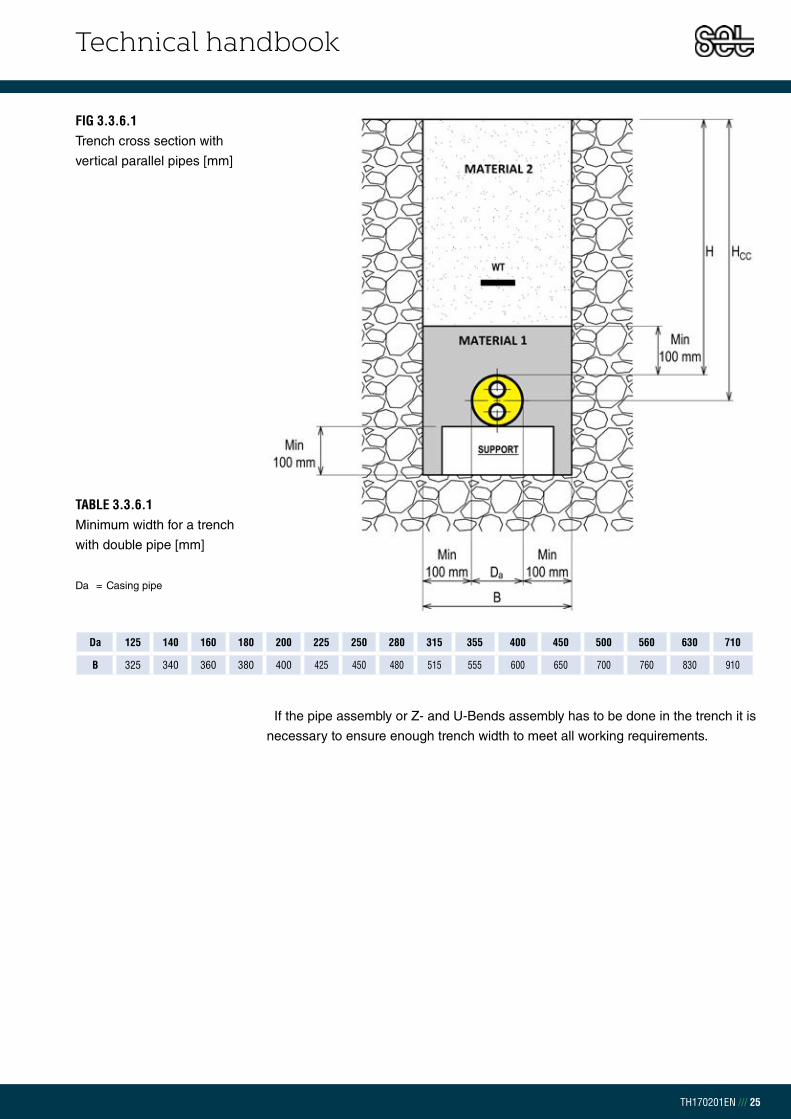
Technical handbook
TH170201EN /// 25
TABLE 3.3.6.1Minimum width for a trench
with double pipe [mm]
Da = Casing pipe
Da 125 140 160 180 200 225 250 280 315 355 400 450 500 560 630 710
B 325 340 360 380 400 425 450 480 515 555 600 650 700 760 830 910
If the pipe assembly or Z- and U-Bends assembly has to be done in the trench it is
necessary to ensure enough trench width to meet all working requirements.
FIG 3.3.6.1Trench cross section with
vertical parallel pipes [mm]

Technical handbook
TH170201EN /// 26
BACKFILLING 1 Before backfilling of the trench the following points must be reviewed:
- Pipe-laying guidelines are followed according to expansion design
- Verification of leak detection system
- Verification jointing is secure
- Stones and foreign objects which may have fallen from trench bank
during assembly are removed
- During preheating , expansion and temperature must be within set limits
and documented.
To minimize heat loss from the ground surface use stone free fine sand that is free
from plant residues, humus, clay and silt lumps.
The sand must comply with following grain sizes to be classified as backfilling material 1:
Begin trench filling with compacted sand ensuring the layer is at least 0,10 m after
compacting. The pipes are placed in the trench with the correct distance between
(B) and the minimum distance from the outer casing and surface is 0,10 m.
It Begin trench filling with compacted sand ensuring the layer is at least 0.10m after
compacting. The pipes are layed in the trench with the correct distance between (B)
and the minimum distance from the outer casing and trench side is 0,10 m.
It is necessary to compact the sand well around the pipes. Ensure the sand is
compacted similtanously on both sides to avoid pipes moving out of place. The
backfill shall be made up in a way that neither its properties nor the compaction
causes damage to pipe and joints.
The sand layer above the district heating pipe should be minimum 0,10 m after
compaction.
MEDIUM GRAINED SAND 0-4 mm
FINE GRAINED SAND Max 8%
MAXIMUM GRAIN SIZE ≤ 32 mm
MAXIMUM GRAIN SIZE 10% OF WEIGHT ≤ 0,075 mm
MAXIMUM GRAIN SIZE 3% OF WEIGHT ≤ 0,020 mm
COEFFICIENT OF UNIFORMITY d60/d10 > 1,8
TABLE 3.3.7.1Backfilling material 1
description
CHAPTER 3.3.7BACKFILLING

Technical handbook
TH170201EN /// 27
BACKFILLING 2Before using backfilling material 2 place a warning type at a distance of approx.
0,20 – 0,50 m above the pipeline. Make sure that the backfilling material 2 doesn´t
damage the pipe or the fittings. In some cases the material from the trench can be
reused, but only if it contains a very small amount of organic material (e.g.
humus and clay). Remove bigger stones/rocks and other undesirable material.
The backfilling should follow in layers and compacted with necessary equipment
which reaches 20 N/cm2. The first backfilling layer must be fine-grained and the
following layer can be coarse, but each layer must always be at least 0,20 m after
compaction.
ANCHOR INSTALLATIONTable 3.3.8.1 og mynd 3.3.8.1 shows how concrete anchor blocks should be
embedded in a compacted, dry soil. Use KS 410 ribbed steel bars for the
reinforcement. Once cementing and other anchor work is complete follow
instructions from backfilling 1. It is important to finish compacting around the
anchor before water is put into the system. The compressive strength has to be 150
kN/m2 after compacting. Please contact Set Pipe´s technical department if further
information regarding anchoring is needed.
STEEL DN
Hc[mm]
Dc[mm]
Bc[mm]
REBAR
NUMBERhorizontal
NUMBER vertical
DIAMETER [mm]
25 500 800 1000 2 2 10
32 500 800 1200 2 2 10
40 500 800 1200 2 2 10
50 500 800 1200 2 2 10
65 800 800 1200 2 2 10
80 800 800 1300 2 2 10
100 800 800 2000 2 2 10
125 1100 800 2000 2 4 12
150 1100 800 2500 2 4 12
200 1400 800 3000 2 4 12
TABLE 3.3.8.1Anchor dimensions
FIG 3.3.8.1Anchor
APPV'D
SHEET 1 OF 1
Festa í steypu WEIGHT:
CHK'D
A3
SCALE:1:50
DWG NO.
TITLE:
REVISIONDO NOT SCALE DRAWING
MATERIAL:
DATESIGNATURE
MFG
Q.A
DEBUR AND
EDGES
BREAK SHARP
NAME
ANGULAR:
FINISH:UNLESS OTHERWISE SPECIFIED:
DIMENSIONS ARE IN MILLIMETERS
SURFACE FINISH:
TOLERANCES:
LINEAR:
DRAWN
Horizontal steelVertical steel
Hc
Bc
Dc Senkrecht Stahl Waagerecht Stahl
Dc/2
Lóðrétt stál Lárétt stál
Festa í steypu WEIGHT:
A3
SHEET 1 OF 1SCALE:1:50
DWG NO.
TITLE:
REVISIONDO NOT SCALE DRAWING
MATERIAL:
DATESIGNATURENAME
DEBUR AND BREAK SHARP EDGES
FINISH:UNLESS OTHERWISE SPECIFIED:DIMENSIONS ARE IN MILLIMETERSSURFACE FINISH:TOLERANCES: LINEAR: ANGULAR:
Q.A
MFG
APPV'D
CHK'D
DRAWN
CHAPTER 3.3.8ANCHOR INSTALLATION

Technical handbook
TH170201EN /// 28
CURVED PIPES Set Pipes supplies insulated curved pipes (R2,min). The pipes are available in
dimensions DN 20 – DN 200. Upon request, it is possible to bend DN 20 – DN 50
more than R2,min if required. It is possible to curve straight pipe on site after they have
been weldet together to the radius R1min.
THUS:R1,min = Minimum bending radius for pipeline on site [m]
R2,min = Minimum bending radius for one pipe [m]
y = Yield strength for steel = 235 MPa
ESt = Modulus of elasticity for steel = 210 Gpa
FIG 3.3.10.1Curved pipe
CHAPTER 3.3.10CURVED PIPES
TABLE 3.3.10.1Curved pipe dimensions
do = Outer diameter of the steel pipe
R1min = Minimum bending radius for
pipeline on site
R2min = Minimum bending radius for
one pipe
1 = Curve angle R1
2 = Curve angle R2
STEELDN
DO[mm]
R1,MIN [m]
R2,MIN [m]
6 m pipes 12 m pipes
1[°] 2[°] 1[°] 2[°]
20 26,9 18,1 6,0 19,0 57,2 38,0 114,4
25 33,7 22,6 7,5 15,2 45,7 30,4 91,3
32 42,4 28,5 9,5 12,1 36,3 24,1 72,6
40 48,3 32,5 10,8 10,6 31,9 21,2 63,7
50 60,3 40,5 13,5 8,5 25,5 17,0 51,0
65 76,1 51,1 17,0 6,7 20,2 13,5 40,4
80 88,9 59,7 19,9 5,8 17,3 11,5 34,6
100 114,3 76,8 25,5 4,5 13,5 9,0 26,9
125 139,7 93,9 31,2 3,7 11,0 7,3 22,0
150 168,3 113,1 37,6 3,0 9,1 6,1 18,3
200 219,1 147,2 48,9 2,3 7,0 4,7 14,0
STEEL WELDINGWelders for welding district heating pipes must carry a valid welding certificate according
to EN 287-1. Qualification of welding procedure specifications (WPS) must be used during
the steel welding process and Set Pipes recommends the use of certified welding procedure
(WPQR) during the welding of pre-insulated district heating pipes. Set Pipes recommends gas
welding for pipes < DN 80 and electric welding for pipes > DN 80. Use welding electrodes of
similar material as the welded steel pipe. Under bad weather conditions place a tent over the
welding area. Clean rust and other dirt from pipe ends surface both inside and outside of the
pipe. Rust and dirt affect the welding quality.
It is recommended to weld joints on wooden plank supports above or beside the trench. If weld-
ing is done after the pipes are in the trench ensure a wide and deep enough trench. If necessary
to shorten a pipe system Set Pipes recommends the pipes rather than the fittings be shortened.
CHAPTER 3.3.9STEEL WELDING

Technical handbook
TH170201EN /// 29
6 metersArt no.
Steel Pipe Casing pipe PUR a [mm]
Weight[kg/pc]DN d [mm] t1[mm] D [mm] t2 [mm]
1.4101.020 20-20 26,9 2,6 125 3,0 19,0 30,4
1.4101.025 25-25 33,7 2,6 140 3,0 19,0 40,2
1.4101.032 32-32 42,4 2,6 160 3,0 19,0 50,4
1.4101.040 40-40 48,3 2,6 160 3,0 19,0 54,9
1.4101.050 50-50 60,3 2,9 200 3,2 20,0 77,8
1.4101.065 65-65 76,1 2,9 225 3,4 20,0 97,2
1.4101.080 80-80 88,9 3,2 250 3,6 25,0 122,5
1.4101.100 100-100 114,3 3,6 315 4,1 25,0 179,9
1.4101.125 125-125 139,7 3,6 400 4,8 30,0 239,7
1.4101.150 150-150 168,3 4,0 450 5,2 40,0 310,7
1.4101.200 200-200 219,1 4,5 560 6,0 45,0 456,5
12 metersArt no.
Steel Pipe Casing pipe PUR a [mm]
Weight[kg/pc]DN d [mm] t1[mm] D [mm] t2 [mm]
1.4102.025 25-25 33,7 2,6 140 3,0 19,0 80,5
1.4102.032 32-32 42,4 2,6 160 3,0 19,0 100,9
1.4102.040 40-40 48,3 2,6 160 3,0 19,0 109,8
1.4102.050 50-50 60,3 2,9 200 3,2 20,0 155,5
1.4102.065 65-65 76,1 2,9 225 3,4 20,0 194,4
1.4102.080 80-80 88,9 3,2 250 3,6 25,0 245,0
1.4102.100 100-100 114,3 3,6 315 4,1 25,0 359,7
1.4102.125 125-125 139,7 3,6 400 4,8 30,0 479,4
1.4102.150 150-150 168,3 4,0 450 5,2 40,0 621,4
1.4102.200 200-200 219,1 4,5 560 6,0 45,0 913,0
CHAPTER 3.9.1PRE-INSULATED DOUBLE STEEL PIPESINSULATION SERIES 1
16 metersArt no.
Steel Pipe Casing pipe PUR a [mm]
Weight[kg/pc]DN d [mm] t1[mm] D [mm] t2 [mm]
1.4103.100 100-100 114,3 3,6 315 4,1 25,0 479,6
1.4103.125 125-125 139,7 3,6 400 4,8 30,0 639,1
1.4103.150 150-150 168,3 4,0 450 5,2 40,0 828,5
1.4103.200 200-200 219,1 4,5 560 6,0 45,0 1217,4
CHAPTER 3.9PRODUCT CATALOGUE
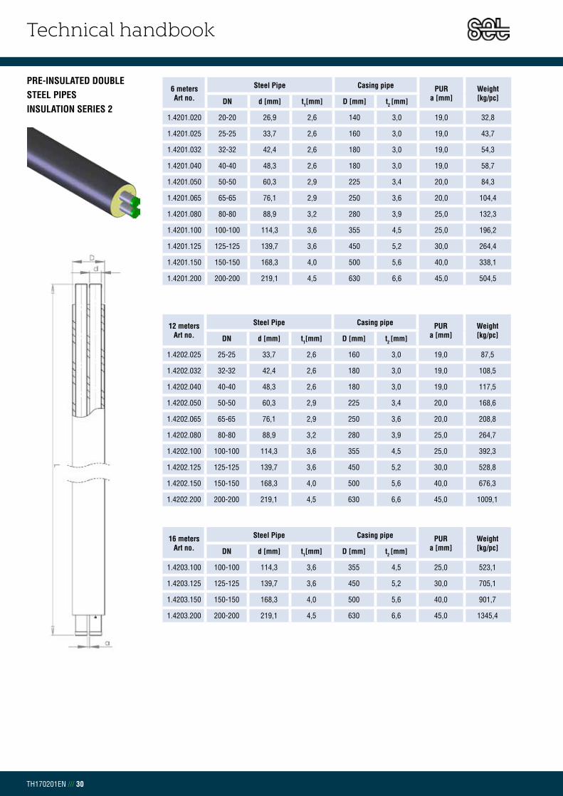
Technical handbook
TH170201EN /// 30
PRE-INSULATED DOUBLE STEEL PIPESINSULATION SERIES 2
6 metersArt no.
Steel Pipe Casing pipe PURa [mm]
Weight[kg/pc]DN d [mm] t1[mm] D [mm] t2 [mm]
1.4201.020 20-20 26,9 2,6 140 3,0 19,0 32,8
1.4201.025 25-25 33,7 2,6 160 3,0 19,0 43,7
1.4201.032 32-32 42,4 2,6 180 3,0 19,0 54,3
1.4201.040 40-40 48,3 2,6 180 3,0 19,0 58,7
1.4201.050 50-50 60,3 2,9 225 3,4 20,0 84,3
1.4201.065 65-65 76,1 2,9 250 3,6 20,0 104,4
1.4201.080 80-80 88,9 3,2 280 3,9 25,0 132,3
1.4201.100 100-100 114,3 3,6 355 4,5 25,0 196,2
1.4201.125 125-125 139,7 3,6 450 5,2 30,0 264,4
1.4201.150 150-150 168,3 4,0 500 5,6 40,0 338,1
1.4201.200 200-200 219,1 4,5 630 6,6 45,0 504,5
12 metersArt no.
Steel Pipe Casing pipe PURa [mm]
Weight[kg/pc]DN d [mm] t1[mm] D [mm] t2 [mm]
1.4202.025 25-25 33,7 2,6 160 3,0 19,0 87,5
1.4202.032 32-32 42,4 2,6 180 3,0 19,0 108,5
1.4202.040 40-40 48,3 2,6 180 3,0 19,0 117,5
1.4202.050 50-50 60,3 2,9 225 3,4 20,0 168,6
1.4202.065 65-65 76,1 2,9 250 3,6 20,0 208,8
1.4202.080 80-80 88,9 3,2 280 3,9 25,0 264,7
1.4202.100 100-100 114,3 3,6 355 4,5 25,0 392,3
1.4202.125 125-125 139,7 3,6 450 5,2 30,0 528,8
1.4202.150 150-150 168,3 4,0 500 5,6 40,0 676,3
1.4202.200 200-200 219,1 4,5 630 6,6 45,0 1009,1
16 metersArt no.
Steel Pipe Casing pipe PURa [mm]
Weight[kg/pc]DN d [mm] t1[mm] D [mm] t2 [mm]
1.4203.100 100-100 114,3 3,6 355 4,5 25,0 523,1
1.4203.125 125-125 139,7 3,6 450 5,2 30,0 705,1
1.4203.150 150-150 168,3 4,0 500 5,6 40,0 901,7
1.4203.200 200-200 219,1 4,5 630 6,6 45,0 1345,4

Technical handbook
TH170201EN /// 31
PRE-INSULATED DOUBLE STEEL PIPESINSULATION SERIES 3
6 metersArt no.
Steel Pipe Casing pipe PURa [mm]
Weight[kg/pc]DN d [mm] t1[mm] D [mm] t2 [mm]
1.4302.020 20-20 26,9 2,6 160 3,0 19,0 36,3
1.4302.025 25-25 33,7 2,6 180 3,0 19,0 47,6
1.4302.032 32-32 42,4 2,6 200 3,2 19,0 59,1
1.4302.040 40-40 48,3 2,6 200 3,2 19,0 63,6
1.4302.050 50-50 60,3 2,9 250 3,6 20,0 91,5
1.4302.065 65-65 76,1 2,9 280 3,9 20,0 114,3
1.4302.080 80-80 88,9 3,2 315 4,1 25,0 144,3
1.4302.100 100-100 114,3 3,6 400 4,8 25,0 215,7
1.4302.125 125-125 139,7 3,6 500 5,6 30,0 291,9
1.4302.150 150-150 168,3 4,0 560 6,0 40,0 373,9
1.4302.200 200-200 219,1 4,5 710 7,2 45,0 565,0
12 metersArt no.
Steel Pipe Casing pipe PURa [mm]
Weight[kg/pc]DN d [mm] t1[mm] D [mm] t2 [mm]
1.4302.025 25-25 33,7 2,6 180 3,0 19,0 95,2
1.4302.032 32-32 42,4 2,6 200 3,2 19,0 118,3
1.4302.040 40-40 48,3 2,6 200 3,2 19,0 127,2
1.4302.050 50-50 60,3 2,9 250 3,6 20,0 183,0
1.4302.065 65-65 76,1 2,9 280 3,9 20,0 228,5
1.4302.080 80-80 88,9 3,2 315 4,1 25,0 288,7
1.4302.100 100-100 114,3 3,6 400 4,8 25,0 431,4
1.4302.125 125-125 139,7 3,6 500 5,6 30,0 583,7
1.4302.150 150-150 168,3 4,0 560 6,0 40,0 747,9
1.4302.200 200-200 219,1 4,5 710 7,2 45,0 1130,1
16 metersArt no.
Steel Pipe Casing pipe PURa [mm]
Weight[kg/pc]DN d [mm] t1[mm] D [mm] t2 [mm]
1.4302.100 100-100 114,3 3,6 400 4,8 25,0 575,2
1.4302.125 125-125 139,7 3,6 500 5,6 30,0 778,3
1.4302.150 150-150 168,3 4,0 560 6,0 40,0 997,2
1.4302.200 200-200 219,1 4,5 710 7,2 45,0 1506,8

Technical handbook
TH170201EN /// 32
CHAPTER 3.9.2DOUBLE BEND 90° HORIZONTALINSULATION SERIES 1
Art no. Steel Pipe DN
Casing pipe D [mm]
LengthL1/L2 [mm]
Weight[kg/pc]
1.4110.020 20-20 125 1000 10,1
1.4110.025 25-25 140 1000 11,1
1.4110.032 32-32 160 1000 13,7
1.4110.040 40-40 160 1000 15,9
1.4110.050 50-50 200 1000 20,6
1.4110.065 65-65 225 1000 26,6
1.4110.080 80-80 250 1000 33,3
1.4110.100 100-100 315 1000 48,1
1.4110.125 125-125 400 1000 62,8
1.4110.150 150-150 450 1200 99,5
1.4110.200 200-200 560 1300 156,1
Art no. Steel Pipe DN
Casing pipe D [mm]
LengthL1/L2 [mm]
Weight[kg/pc]
1.4114.020 20-20 125 1000 9,3
1.4114.025 25-25 140 1000 10,2
1.4114.032 32-32 160 1000 12,6
1.4114.040 40-40 160 1000 14,7
1.4114.050 50-50 200 1000 19,0
1.4114.065 65-65 225 1000 24,5
1.4114.080 80-80 250 1000 30,7
1.4114.100 100-100 315 1000 44,3
1.4114.125 125-125 400 1000 57,8
1.4114.150 150-150 450 1200 91,5
1.4114.200 200-200 560 1300 143,6
Art no. Steel Pipe DN
Casing pipe D [mm]
LengthL1/L2 [mm]
Weight[kg/pc]
1.4111.020 20-20 125 1000 10,1
1.4111.025 25-25 140 1000 11,1
1.4111.032 32-32 160 1000 13,7
1.4111.040 40-40 160 1000 15,9
1.4111.050 50-50 200 1000 20,6
1.4111.065 65-65 225 1000 26,6
1.4111.080 80-80 250 1000 33,3
1.4111.100 100-100 315 1000 48,1
1.4111.125 125-125 400 1000 62,8
1.4111.150 150-150 450 1200 99,5
1.4111.200 200-200 560 1300 156,1
Art no. Steel Pipe DN
Casing pipe D [mm]
LengthL1/L2 [mm]
Weight[kg/pc]
1.4115.020 20-20 125 1000 9,3
1.4115.025 25-25 140 1000 10,2
1.4115.032 32-32 160 1000 12,6
1.4115.040 40-40 160 1000 14,7
1.4115.050 50-50 200 1000 19,0
1.4115.065 65-65 225 1000 24,5
1.4115.080 80-80 250 1000 30,7
1.4115.100 100-100 315 1000 44,3
1.4115.125 125-125 400 1000 57,8
1.4115.150 150-150 450 1200 91,5
1.4115.200 200-200 560 1300 143,6
DOUBLE BEND 30°, 45° & 60° VERTICAL ISOLATION SERIES 1
DOUBLE BEND 30°, 45° & 60° HORIZONTALINSULATION SERIES 1
DOUBLE BEND 90° VERTICALINSULATION SERIES 1

Technical handbook
TH170201EN /// 33
Art no. Steel Pipe DN
Casing pipe D [mm]
LengthL1/L2 [mm]
Weight[kg/pc]
1.4210.020 20-20 140 1000 10,6
1.4210.025 25-25 160 1000 11,9
1.4210.032 32-32 180 1000 14,8
1.4210.040 40-40 180 1000 17,0
1.4210.050 50-50 225 1000 22,3
1.4210.065 65-65 250 1000 28,6
1.4210.080 80-80 280 1000 35,9
1.4210.100 100-100 355 1000 52,4
1.4210.125 125-125 450 1000 69,1
1.4210.150 150-150 500 1200 108,6
Art no. Steel Pipe DN
Casing pipe D [mm]
LengthL1/L2 [mm]
Weight[kg/pc]
1.4214.020 20-20 140 1000 9,7
1.4214.025 25-25 160 1000 11,0
1.4214.032 32-32 180 1000 13,6
1.4214.040 40-40 180 1000 15,6
1.4214.050 50-50 225 1000 20,5
1.4214.065 65-65 250 1000 26,3
1.4214.080 80-80 280 1000 33,1
1.4214.100 100-100 355 1000 48,2
1.4214.125 125-125 450 1000 63,6
1.4214.150 150-150 500 1200 99,9
Art no. Steel Pipe DN
Casing pipe D [mm]
LengthL1/L2 [mm]
Weight[kg/pc]
1.4211.020 20-20 140 1000 10,6
1.4211.025 25-25 160 1000 11,9
1.4211.032 32-32 180 1000 14,8
1.4211.040 40-40 180 1000 17,0
1.4211.050 50-50 225 1000 22,3
1.4211.065 65-65 250 1000 28,6
1.4211.080 80-80 280 1000 35,9
1.4211.100 100-100 355 1000 52,4
1.4211.125 125-125 450 1000 69,1
1.4211.150 150-150 500 1200 108,6
Art no. Steel Pipe DN
Casing pipe D [mm]
LengthL1/L2 [mm]
Weight[kg/pc]
1.4215.020 20-20 140 1000 9,7
1.4215.025 25-25 160 1000 11,0
1.4215.032 32-32 180 1000 13,6
1.4215.040 40-40 180 1000 15,6
1.4215.050 50-50 225 1000 20,5
1.4215.065 65-65 250 1000 26,3
1.4215.080 80-80 280 1000 33,1
1.4215.100 100-100 355 1000 48,2
1.4215.125 125-125 450 1000 63,6
1.4215.150 150-150 500 1200 99,9
DOUBLE BEND 90° HORIZONTALINSULATION SERIES 2
DOUBLE BEND 90° VERTICALINSULATION SERIES 2
DOUBLE BEND 30°, 45° & 60° HORIZONTALINSULATION SERIES 2
DOUBLE BEND 30°, 45° & 60° VERTICAL ISOLATION SERIES 2

Technical handbook
TH170201EN /// 34
CHAPTER 3.9.3DOUBLE T-PIECESINSULATION SERIES 1
Art no.Main pipe Branch
Length L1/L2 [mm]
Weight[kg/pc]Steel Pipe
DNCasing pipe
D1 [mm]Steel Pipe
DNCasing pipe
D2 [mm]
14.120.020.020 20-20 125 20-20 125 1000/800 9,4
14.120.025.020 25-25 140 20-20 125 1000/800 9,4
14.120.025.025 25-25 140 25-25 140 1000/800 9,7
14.120.032.020 32-32 160 20-20 125 1000/800 10,8
14.120.032.025 32-32 160 25-25 140 1000/800 11,1
14.120.032.032 32-32 160 32-32 160 1000/800 12,2
14.120.040.020 40-40 160 20-20 125 1000/800 11,7
14.120.040.025 40-40 160 25-25 140 1000/800 12,1
14.120.040.032 40-40 160 32-32 160 1000/800 13,2
14.120.040.040 40-40 160 40-40 160 1000/800 14,0
14.120.050.020 50-50 200 20-20 125 1000/800 14,5
14.120.050.025 50-50 200 25-25 140 1000/800 14,9
14.120.050.032 50-50 200 32-32 160 1000/800 16,0
14.120.050.040 50-50 200 40-40 160 1000/800 16,8
14.120.050.050 50-50 200 50-50 200 1200/800 21,4
14.120.065.020 65-65 225 20-20 125 1000/800 17,3
14.120.065.025 65-65 225 25-25 140 1000/800 17,6
14.120.065.032 65-65 225 32-32 160 1000/800 18,7
14.120.065.040 65-65 225 40-40 160 1000/800 19,5
14.120.065.050 65-65 225 50-50 200 1200/800 24,7
14.120.065.065 65-65 225 65-65 225 1200/800 26,8
14.120.080.025 80-80 250 25-25 140 1000/800 21,2
14.120.080.032 80-80 250 32-32 160 1000/800 22,3
14.120.080.040 80-80 250 40-40 160 1000/800 23,1
14.120.080.050 80-80 250 50-50 200 1200/800 29,1
14.120.080.065 80-80 250 65-65 225 1200/800 31,2
14.120.080.080 80-80 250 80-80 250 1200/800 34,0
14.120.100.025 100-100 315 25-25 140 1000/800 29,3
14.120.100.032 100-100 315 32-32 160 1000/800 30,3
14.120.100.040 100-100 315 40-40 160 1000/800 31,2
14.120.100.050 100-100 315 50-50 200 1200/800 39,0
14.120.100.065 100-100 315 65-65 225 1200/800 41,1
14.120.100.080 125-125 315 80-80 250 1200/800 43,8
14.120.100.100 100-100 315 100-100 315 1200/800 49,7
14.120.125.025 125-125 400 25-25 140 1000/900 38,0
14.120.125.032 125-125 400 32-32 160 1000/900 39,2
14.120.125.040 125-125 400 40-40 160 1000/900 40,1
14.120.125.050 125-125 400 50-50 200 1200/900 50,3
14.120.125.065 125-125 400 65-65 225 1200/900 52,6
14.120.125.080 125-125 400 80-80 250 1200/900 55,7
14.120.125.100 125-125 400 100-100 315 1400/900 70,3
14.120.125.125 125-125 400 125-125 400 1400/900 76,9
14.120.150.025 150-150 450 25-25 140 1000/900 48,2
14.120.150.032 150-150 450 32-32 160 1000/900 49,3
14.120.150.040 150-150 450 40-40 160 1000/900 50,2
14.120.150.050 150-150 450 50-50 200 1200/900 62,7
14.120.150.065 150-150 450 65-65 225 1200/900 65,0
14.120.150.080 150-150 450 80-80 250 1200/900 68,0
D1D2a2 a1
L1
200
200
200
L2

Technical handbook
TH170201EN /// 35
DOUBLE T-PIECESINSULATION SERIES 1 Art no.
Main pipe BranchLength
L1/L2 [mm]Weight[kg/pc]Steel Pipe
DNCasing pipe
D1 [mm]Steel Pipe
DNCasing pipe
D2 [mm]
14.120.150.100 150-150 450 100-100 315 1400/900 84,8
14.120.150.125 150-150 450 125-125 400 1400/900 91,3
14.120.150.150 150-150 450 150-150 450 1400/900 99,4
14.120.200.025 200-200 560 25-25 140 1000/1000 69,7
14.120.200.032 200-200 560 32-32 160 1000/1000 72,2
14.120.200.040 200-200 560 40-40 160 1000/1000 72,0
14.120.200.050 200-200 560 50-50 200 1200/1000 89,7
14.120.200.065 200-200 560 65-65 225 1200/1000 92,2
14.120.200.080 200-200 560 80-80 250 1200/1000 95,5
14.120.200.100 200-200 560 100-100 315 1400/1000 118,1
14.120.200.125 200-200 560 125-125 400 1400/1000 125,3
14.120.200.200 200-200 560 200-200 500 1400/1000 152,4
D1D2a2 a1
L1
200
200
200
L2

Technical handbook
TH170201EN /// 36
DOUBLE T-PIECESINSULATION SERIES 2 Art no.
Main pipe BranchLength
L1/L2 [mm]Weight[kg/pc]Steel Pipe
DNCasing pipe
D1 [mm]Steel Pipe
DNCasing pipe
D2 [mm]
14.220.020.020 20-20 140 20-20 140 1000/800 9,4
14.220.025.020 25-25 160 20-20 140 1000/800 9,9
14.220.025.025 25-25 160 25-25 160 1000/800 10,4
14.220.032.020 32-32 180 20-20 140 1000/800 11,4
14.220.032.025 32-32 180 25-25 160 1000/800 11,9
14.220.032.032 32-32 180 32-32 180 1000/800 13,0
14.220.040.020 40-40 180 20-20 140 1000/800 12,4
14.220.040.025 40-40 180 25-25 160 1000/800 12,9
14.220.040.032 40-40 180 32-32 180 1000/800 14,1
14.220.040.040 40-40 180 40-40 180 1000/800 14,9
14.220.050.020 50-50 225 20-20 140 1000/800 15,4
14.220.050.025 50-50 225 25-25 160 1000/800 15,9
14.220.050.032 50-50 225 32-32 180 1000/800 17,0
14.220.050.040 50-50 225 40-40 180 1000/800 17,8
14.220.050.050 50-50 225 50-50 225 1200/800 22,8
14.220.065.020 65-65 250 20-20 140 1000/800 18,3
14.220.065.025 65-65 250 25-25 160 1000/800 18,7
14.220.065.032 65-65 250 32-32 180 1000/800 19,9
14.220.065.040 65-65 250 40-40 180 1000/800 20,7
14.220.065.050 65-65 250 50-50 225 1200/800 26,3
14.220.065.065 65-65 250 65-65 250 1200/800 28,5
14.220.080.025 80-80 280 25-25 160 1000/800 22,6
14.220.080.032 80-80 280 32-32 180 1000/800 23,7
14.220.080.040 80-80 280 40-40 180 1000/800 24,5
14.220.080.050 80-80 280 50-50 225 1200/800 31,1
14.220.080.065 80-80 280 65-65 250 1200/800 33,2
14.220.080.080 80-80 280 80-80 280 1200/800 36,2
14.220.100.025 100-100 355 25-25 160 1000/800 31,4
14.220.100.032 100-100 355 32-32 180 1000/800 32,4
14.220.100.040 100-100 355 40-40 180 1000/800 33,3
14.220.100.050 100-100 355 50-50 225 1200/800 41,9
14.220.100.065 100-100 355 65-65 250 1200/800 44,0
14.220.100.080 100-100 355 80-80 280 1200/800 46,9
14.220.100.100 100-100 355 100-100 355 1200/800 53,3
14.220.125.025 125-125 450 25-25 160 1000/900 41,1
14.220.125.032 125-125 450 32-32 180 1000/900 42,3
14.220.125.040 125-125 450 40-40 180 1000/900 43,3
14.220.125.050 125-125 450 50-50 225 1200/900 54,6
1.4220.125.050 125-125 450 50-50 225 1200/900 54,6
1.4220.125.065 125-125 450 65-65 250 1200/900 57,0
1.4220.125.080 125-125 450 80-80 280 1200/900 60,2
1.4220.125.100 125-125 450 100-100 355 1400/900 76,3
14.220.125.125 125-125 450 125-125 450 1400/900 83,4
14.220.150.025 150-150 500 25-25 160 1000/900 51,7
14.220.150.032 150-150 500 32-32 180 1000/900 52,9
14.220.150.040 150-150 500 40-40 180 1000/900 53,8
14.220.150.050 150-150 500 50-50 225 1200/900 67,6
D1D2a2 a1
L1
200
200
200
L2
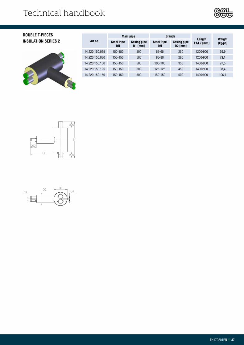
Technical handbook
TH170201EN /// 37
DOUBLE T-PIECESINSULATION SERIES 2 Art no.
Main pipe BranchLength
L1/L2 [mm]Weight[kg/pc]Steel Pipe
DNCasing pipe
D1 [mm]Steel Pipe
DNCasing pipe
D2 [mm]
14.220.150.065 150-150 500 65-65 250 1200/900 69,9
14.220.150.080 150-150 500 80-80 280 1200/900 73,1
14.220.150.100 150-150 500 100-100 355 1400/900 91,5
14.220.150.125 150-150 500 125-125 450 1400/900 98,4
14.220.150.150 150-150 500 150-150 500 1400/900 106,7
D1D2a2 a1
L1
200
200
200
L2

Technical handbook
TH170201EN /// 38
CHAPTER 3.9.4DOUBLE REDUCTIONINSULATION SERIES 1
Art no. Steel Pipe DN
Casing pipe D1/D2 [mm]
Length L [mm]
Weight[kg/pc]
1.4130.025.020 25-20 140/125 1000 3,2
1.4130.032.020 32-20 160/125 1000 3,6
1.4130.032.025 32-25 160/140 1000 3,8
1.4130.040.020 40-20 160/125 1000 4,0
1.4130.040.025 40-25 160/140 1000 4,2
1.4130.050.020 50-20 200/125 1000 4,8
1.4130.050.025 50-25 200/140 1000 5,0
1.4130.050.032 50-32 200/160 1000 5,4
1.4130.050.040 50-40 200/160 1000 5,8
1.4130.065.020 65-20 225/125 1000 5,6
1.4130.065.025 65-25 225/140 1000 5,8
1.4130.065.032 65-32 225/160 1000 6,2
1.4130.065.040 65-40 225/160 1000 6,6
1.4130.065.050 65-50 225/200 1000 7,3
1.4130.080.020 80-20 250/125 1000 6,7
1.4130.080.025 80-25 250/140 1000 6,8
1.4130.080.032 80-32 250/160 1000 7,3
1.4130.080.040 80-40 250/160 1000 7,7
1.4130.080.050 80-50 250/200 1000 8,4
1.4130.080.065 80-65 250/225 1000 9,2
1.4130.100.020 100-20 315/125 1000 9,2
1.4130.100.025 100-25 315/140 1000 9,4
1.4130.100.032 100-32 315/160 1000 9,8
1.4130.100.040 100-40 315/160 1000 10,2
1.4130.100.050 100-50 315/200 1000 11,0
1.4130.100.065 100-65 315/225 1000 11,8
1.4130.100.080 100-80 315/250 1000 12,9
1.4130.125.020 125-20 400/125 1500 20,0
1.4130.125.025 125-25 400/140 1500 20,3
1.4130.125.032 125-32 400/160 1500 20,9
1.4130.125.040 125-40 400/160 1500 21,6
1.4130.125.050 125-50 400/200 1500 22,8
1.4130.125.065 125-65 400/225 1500 24,1
1.4130.125.080 125-80 400/250 1500 25,8
1.4130.125.100 125-100 400/315 1500 30,0
1.4130.150.020 150-20 450/125 1500 24,9
1.4130.150.025 150-25 450/140 1500 25,2
1.4130.150.032 150-32 450/160 1500 25,9
1.4130.150.040 150-40 450/160 1500 26,6
1.4130.150.050 150-50 450/200 1500 27,7
1.4130.150.065 150-65 450/225 1500 29,0
1.4130.150.080 150-80 450/250 1500 30,8
1.4130.150.100 150-100 450/315 1500 34,9
1.4130.150.125 150-125 450/400 1500 39,9
1.4130.200.020 200-20 560/125 1500 36,0
1.4130.200.025 200-25 560/140 1500 36,3
1.4130.200.032 200-32 560/160 1500 37,0
1.4130.200.040 200-40 560/180 1500 37,7

Technical handbook
TH170201EN /// 39
DOUBLE REDUCTIONINSULATION SERIES 1
Art no. Steel Pipe DN
Casing pipe D1/D2 [mm]
Length L [mm]
Weight[kg/pc]
1.4130.200.050 200-50 560/200 1500 38,8
1.4130.200.065 200-65 560/225 1500 40,1
1.4130.200.080 200-80 560/250 1500 41,9
1.4130.200.100 200-100 560/315 1500 46,0
1.4130.200.125 200-125 560/400 1500 51,0
1.4130.200.150 200-150 560/450 1500 56,0

Technical handbook
TH170201EN /// 40
DOUBLE REDUCTIONINSULATION SERIES 2
Art no. Steel Pipe DN
Casing pipe D1/D2 [mm]
Length L [mm]
Weight[kg/pc]
1.4230.025.020 25-20 160/140 1000 3,3
1.4230.032.020 32-20 180/140 1000 3,8
1.4230.032.025 32-25 180/160 1000 4,0
1.4230.040.020 40-20 180/140 1000 4,1
1.4230.040.025 40-25 180/160 1000 4,3
1.4230.050.020 50-20 225/140 1000 5,0
1.4230.050.025 50-25 225/160 1000 5,1
1.4230.050.032 50-32 225/180 1000 5,6
1.4230.050.040 50-40 225/180 1000 6,0
1.4230.065.020 65-20 250/140 1000 5,8
1.4230.065.025 65-25 250/160 1000 6,0
1.4230.065.032 65-32 250/180 1000 6,5
1.4230.065.040 65-40 250/180 1000 6,8
1.4230.065.050 65-50 250/225 1000 7,6
1.4230.080.020 80-20 280/140 1000 7,0
1.4230.080.025 80-25 280/160 1000 7,1
1.4230.080.032 80-32 280/180 1000 7,6
1.4230.080.040 80-40 280/180 1000 8,0
1.4230.080.050 80-50 280/225 1000 8,8
1.4230.080.065 80-65 280/250 1000 9,6
1.4230.100.020 100-20 355/140 1000 9,7
1.4230.100.025 100-25 355/160 1000 9,8
1.4230.100.032 100-32 355/180 1000 10,3
1.4230.100.040 100-40 355/180 1000 10,7
1.4230.100.050 100-50 355/225 1000 11,5
1.4230.100.065 100-65 355/250 1000 12,3
1.4230.100.080 100-80 355/280 1000 13,5
1.4230.125.020 125-20 450/140 1500 21,1
1.4230.125.025 125-25 450/160 1500 21,4
1.4230.125.032 125-32 450/180 1500 22,1
1.4230.125.040 125-40 450/180 1500 22,7
1.4230.125.050 125-50 450/225 1500 24,0
1.4230.125.065 125-65 450/250 1500 25,4
1.4230.125.080 125-80 450/280 1500 27,2
1.4230.125.100 125-100 450/355 1500 31,7
1.4230.150.020 150-20 500/140 1500 26,2
1.4230.150.025 150-25 500/160 1500 26,5
1.4230.150.032 150-32 500/180 1500 27,3
1.4230.150.040 150-40 500/180 1500 27,9
1.4230.150.050 150-50 500/225 1500 29,2
1.4230.150.065 150-65 500/250 1500 30,6
1.4230.150.080 150-80 500/280 1500 32,4
1.4230.150.100 150-100 500/355 1500 36,9
1.4230.150.125 150-125 500/450 1500 42,2

Technical handbook
TH170201EN /// 41
Art no.Main pipe Branch Length
L1/L2 [mm]
Weight[kg/pc]Steel Pipe
DNCasing pipe
D [mm]Steel Pipe
DNCasing pipe
D [mm]
1.4121.020 20 125 20 90 1000/300 6,0
1.4121.025 25 140 25 90 1000/300 7,8
1.4121.032 32 160 32 110 1000/320 9,8
1.4121.040 40 160 40 110 1000/320 10,6
1.4121.050 50 200 50 125 1200/340 15,4
1.4121.065 65 225 65 140 1200/340 19,2
1.4121.080 80 250 80 160 1200/400 24,5
1.4121.100 100 315 100 200 1400/420 40,4
1.4121.125 125 400 125 225 1400/450 59,3
1.4121.150 150 450 150 250 1400/500 81,3
1.4121.200 200 560 200 315 1600/600 125,4
CHAPTER 3.9.5TRANSITION FORK DOUBLE TO SINGLE INSULATION SERIES 1
TRANSITION FORK DOUBLE TO SINGLE INSULATION SERIES 2
Art no.Main pipe Branch Length
L1/L2 [mm]
Weight[kg/pc]Steel Pipe
DNCasing pipe
D [mm]Steel Pipe
DNCasing pipe
D [mm]
1.4221.020 20 140 20 110 1000/300 6,5
1.4221.025 25 160 25 110 1000/300 8,4
1.4221.032 32 180 32 125 1000/320 10,6
1.4221.040 40 180 40 125 1000/320 11,4
1.4221.050 50 225 50 140 1200/340 16,6
1.4221.065 65 250 65 150 1200/340 20,7
1.4221.080 80 280 80 180 1200/400 26,5
1.4221.100 100 355 100 225 1400/420 43,6
1.4221.125 125 450 125 250 1400/450 64,0
1.4221.150 150 500 150 280 1400/500 87,8
* Please contact Set Pipes technical department for different types of connections.
* Please contact Set Pipes technical department for different types of connections.

Technical handbook
TH170201EN /// 42
Art no.Main pipe Branch Length
L1/L2 [mm]
Weight[kg/pc]Steel Pipe
DNCasing pipe
D [mm]Steel Pipe
DNCasing pipe
D [mm]
1.4122.020 20 125 20 90 1000/300 6,8
1.4122.025 25 140 25 90 1000/300 8,8
1.4122.032 32 160 32 110 1000/320 11,1
1.4122.040 40 160 40 110 1000/320 12,0
1.4122.050 50 200 50 125 1200/340 17,3
1.4122.065 65 225 65 140 1200/340 21,5
1.4122.080 80 250 80 160 1200/400 27,2
1.4122.100 100 315 100 200 1400/420 42,7
1.4122.125 125 400 125 225 1400/450 62,0
1.4122.150 150 450 150 250 1400/500 80,3
1.4122.200 200 560 200 315 1600/600 120,9
CHAPTER 3.9.6TRANSITION Y FROM DOUBLE TO SINGLEINSULATION SERIES 1
TRANSITION Y FROM DOUBLE TO SINGLEINSULATION SERIES 2
Art no.Main pipe Branch Length
L1/L2 [mm]
Weight[kg/pc]Steel Pipe
DNCasing pipe
D [mm]Steel Pipe
DNCasing pipe
D [mm]
1.4222.020 20 140 20 110 1000/300 7,4
1.4222.025 25 160 25 110 1000/300 9,5
1.4222.032 32 180 32 125 1000/320 12,0
1.4222.040 40 180 40 125 1000/320 13,0
1.4222.050 50 225 50 140 1200/340 18,7
1.4222.065 65 250 65 160 1200/340 23,3
1.4222.080 80 280 80 180 1200/400 29,4
1.4222.100 100 355 100 225 1400/420 46,1
1.4222.125 125 450 125 250 1400/450 67,0
1.4222.150 150 500 150 280 1400/500 86,7
* Please contact Set Pipes technical department for different types of connections.
* Please contact Set Pipes technical department for different types of connections.

Technical handbook
TH170201EN /// 43
Art no.Main pipe Branch Length
L1/L2 [mm]
C-C[mm]
L3[mm]
Weight[kg/pc]Steel Pipe
DNCasing pipe
D [mm]Steel Pipe
DNCasing pipe
D [mm]
1.4123.020 20 125 20 90 1200/800 300 805 10,4
1.4123.025 25 140 25 90 1200/800 300 805 13,0
1.4123.032 32 160 32 110 1200/800 320 775 16,4
1.4123.040 40 160 40 110 1200/800 320 775 17,8
1.4123.050 50 200 50 125 1200/800 340 747 24,6
1.4123.065 65 225 65 140 1200/800 340 740 30,5
1.4123.080 80 250 80 160 1200/800 400 670 38,8
1.4123.100 100 315 100 200 1400/800 420 830 58,5
1.4123.125 125 400 125 225 1400/800 450 788 74,8
1.4123.150 150 450 150 250 1600/1000 500 925 98,9
1.4123.200 200 560 200 315 1600/1000 600 792 145,2
CHAPTER 3.9.7TRANSITION Y FROM DOUBLE TO SINGLEINSULATION SERIES 1
TRANSITION Y FROM DOUBLE TO SINGLEINSULATION SERIES 2
Art no.Main pipe Branch Length
L1/L2 [mm]
C-C[mm]
L3[mm]
Weight[kg/pc]Steel Pipe
DNCasing pipe
D [mm]Steel Pipe
DNCasing pipe
D [mm]
1.4223.020 20 140 20 110 1200/800 300 795 11,2
1.4223.025 25 160 25 110 1200/800 300 795 14,1
1.4223.032 32 180 32 125 1200/800 320 768 17,7
1.4223.040 40 180 40 125 1200/800 320 768 19,2
1.4223.050 50 225 50 140 1200/800 340 740 26,6
1.4223.065 65 250 65 160 1200/800 340 730 33,0
1.4223.080 80 280 80 180 1200/800 400 660 41,9
1.4223.100 100 355 100 225 1400/800 420 818 63,1
1.4223.125 125 450 125 250 1400/800 450 775 80,8
1.4223.150 150 500 150 280 1600/1000 500 910 106,8
* Please contact Set Pipes technical department for different types of connections.
* Please contact Set Pipes technical department for different types of connections.

Technical handbook
TH170201EN /// 44
CHAPTER 3.9.8DOUBLE ANCHORINSULATION SERIES 1
DOUBLE ANCHORINSULATION SERIES 2
Art no. Steel Pipe DN
Casing pipe D [mm]
Length L [mm]
Anchor plate Weight[kg/pc]B [mm] t [mm]
1.4140.020 20-20 125 2000 260 20 18,3
1.4140.025 25-25 125 2000 260 20 19,9
1.4140.032 32-32 160 2000 260 20 23,1
1.4140.040 40-40 160 2000 300 25 31,4
1.4140.050 50-50 200 2000 300 25 37,4
1.4140.065 65-65 225 2000 340 25 47,5
1.4140.080 80-80 250 2000 400 25 63,0
1.4140.100 100-100 315 2000 450 25 86,2
1.4140.125 125-125 400 2000 560 30 133,7
1.4140.150 150-150 450 2000 600 30 163,0
1.4140.200 200-200 560 2000 710 30 233,6
Art no. Steel Pipe DN
Casing pipe D [mm]
Length L [mm]
Anchor plate Weight[kg/pc]B [mm] t [mm]
1.4240.020 20-20 140 2000 260 20 18,7
1.4240.025 25-25 140 2000 260 20 20,3
1.4240.032 32-32 180 2000 300 25 30,8
1.4240.040 40-40 200 2000 300 25 33,0
1.4240.050 50-50 225 2000 340 25 43,5
1.4240.065 65-65 250 2000 400 25 57,5
1.4240.080 80-80 280 2000 450 25 73,0
1.4240.100 100-100 355 2000 450 25 89,1
1.4240.125 125-125 450 2000 710 30 183,2
1.4240.150 150-150 500 2000 780 25 203,7
tL
D
200 200
B
B

Technical handbook
TH170201EN /// 45
CHAPTER 3.9.9DOUBLE VALVEINSULATION SERIES 1
Art no. Steel Pipe DN
Casing pipe D [mm]
Spindle height H [mm]
LengthL [mm]
Weight[kg/pc]
1.4145.025 25-25 140 111 1700 15,6
1.4145.032 32-32 160 123 1700 19,1
1.4145.040 40-40 160 133 1700 21,2
1.4145.050 50-50 200 152 1700 29,0
1.4145.065 65-65 225 165 1700 36,0
1.4145.080 80-80 250 184 1900 50,9
1.4145.100 100-100 315 209 2200 91,9
1.4145.125 125-125 400 241 2200 127,0
1.4145.150 150-150 450 282 2600 202,4
1.4145.200 200-200 560 336 2600 310,9
Art no. Steel Pipe DN
Casing pipe D [mm]
Spindle height H [mm]
LengthL [mm]
Weight[kg/pc]
1.4245.025 25-25 160 111 1700 16,8
1.4245.032 32-32 180 123 1700 20,5
1.4245.040 40-40 180 133 1700 22,5
1.4245.050 50-50 225 152 1700 31,2
1.4245.065 65-65 250 165 1700 38,5
1.4245.080 80-80 280 184 1900 55,0
1.4245.100 100-100 355 209 2200 101,0
1.4245.125 125-125 450 241 2200 141,1
1.4245.150 150-150 500 282 2600 224,4
DOUBLE VALVE – 1 SERVICE VALVEINSULATION SERIES 1
Art no. Steel Pipe DN
Casing pipe D [mm]
VentDN
Spindle heightH [mm]
LengthL [mm]
Weight[kg/pc]
1.4146.025 25-25 140 25 382 1700 17,3
1.4146.032 32-32 160 25 388 1700 19,1
1.4146.040 40-40 160 25 401 1700 21,2
1.4146.050 50-50 200 40 411 1700 29,0
1.4146.065 65-65 225 40 415 1700 36,0
1.4146.080 80-80 250 40 426 1900 50,9
1.4146.100 100-100 315 40 450 2200 91,9
1.4146.125 125-125 400 40 455 2200 127,0
1.4146.150 150-150 450 40 475 2600 202,4
1.4146.200 200-200 560 50 520 2600 310,9
Art no. Steel Pipe DN
Casing pipe D [mm]
VentDN
Spindle height H [mm]
LengthL [mm]
Weight[kg/pc]
1.4246.025 25-25 160 25 382 1700 17,8
1.4246.032 32-32 180 25 388 1700 20,5
1.4246.040 40-40 180 25 401 1700 22,5
1.4246.050 50-50 225 40 411 1700 31,2
1.4246.065 65-65 250 40 415 1700 38,5
1.4246.080 80-80 280 40 426 1900 55,0
1.4246.100 100-100 355 40 450 2200 101,0
1.4246.125 125-125 450 40 455 2200 141,1
1.4246.150 150-150 500 40 475 2600 224,4
DOUBLE VALVE – 1 SERVICE VALVEINSULATION SERIES 2
DOUBLE VALVEINSULATION SERIES 2

Technical handbook
TH170201EN /// 46
DOUBLE VALVE – 2 SERVICE VALVE INSULATION SERIES 1
Art no. Steel Pipe DN
Casing pipe D1 [mm]
VentDN
Spindle height H [mm]
LengthL [mm]
Weight[kg/pc]
1.4147.025 25 140 25 382 1700 19,1
1.4147.032 32 160 25 388 1700 22,7
1.4147.040 40 160 25 401 1700 24,8
1.4147.050 50 200 40 411 1700 35,0
1.4147.065 65 225 40 415 1700 42,0
1.4147.080 80 250 40 426 1900 57,0
1.4147.100 100 315 40 450 2200 98,1
1.4147.125 125 400 40 455 2200 133,2
1.4147.150 150 450 40 475 2600 208,8
1.4147.200 200 560 50 520 2600 320,3
DOUBLE VALVE – 2 SERVICE VALVE INSULATION SERIES 2
Art no. Steel Pipe DN
Casing pipe D1 [mm]
VentDN
Spindle height H [mm]
LengthL [mm]
Weight[kg/pc]
1.4247.025 25 160 25 382 1700 20,3
1.4247.032 32 180 25 388 1700 24
1.4247.040 40 180 25 401 1700 26,1
1.4247.050 50 225 40 411 1700 37,2
1.4247.065 65 250 40 415 1700 44,5
1.4247.080 80 280 40 426 1900 61,1
1.4247.100 100 355 40 450 2200 107,3
1.4247.125 125 450 40 455 2200 147,4
1.4247.150 150 500 40 475 2600 230,8
Technical handbook
TH170201EN
Chapter 4 | Flexible pipes
4.0 – Flexible pipes ............................................................................................. 1
4.0.1 – EliPex ..................................................................................................... 1
4.0.2 – EliCopp ................................................................................................. 6
4.0.3 – EliSteel .................................................................................................. 8
4.0.4 – EliAlpex ............................................................................................... 10
4.1 – Application range ................................................................................... 12
4.1.1 – Heat demand ................................................................................... 12
4.1.2 – Pressure loss ..................................................................................... 13
4.1.3 – Heat loss ............................................................................................ 22
4.2 – Transport and storage .......................................................................... 31
4.3 – Field work .................................................................................................. 33
4.3.1 – Weather conditions ....................................................................... 33
4.3.2 – Trench ................................................................................................ 33
4.3.3 – Backfilling ......................................................................................... 37
4.3.4 – Bending radius – flexible pipes ................................................. 38
4.9 – Product catalogue ................................................................................ 39
TABLE OF CONTENT

Technical handbook
TH170201EN /// 1
CHAPTER 4.0FLEXIBLE PIPES
CHAPTER 4.0.1 ELIPEX
EliPex pre-insulated flexible pipes are produced from PEX-a, polyurethane foam
(PUR) and polyethylene casing pipe (PEL). Available in SDR 7,4 and SDR 11, single
and double pipe coils in 20 mm to 125 mm. PEX-a pipe has significant advantages
compared to other types of Pex pipes. In production it is guaranteed the cross
binding is > 85%.
See chapter 4.9 for detailed descriptions of dimensions and sizes. Set Pipes can
offer insulation of other products not specified in our product catalogue, for special
requests please contact our technical department.
APPLICATION RANGE This specification is made for pre-insulated Elipex single and double pipes for
district heating.
Set Pipes manufactures flexible pipes using continuous technology that ensures
consistent insula-tions foam quality. The technology involves long service pipe units
being insulated in a continuous process and the outer casing pipe produced in the
same process. The insulated foam and casing pipe is the same for EliPex, EliCopp,
EliSteel and EliAlpex, produced in insulations series 1 and 2. The pipes are flexible
and are suitable for long pipelines and house connection.
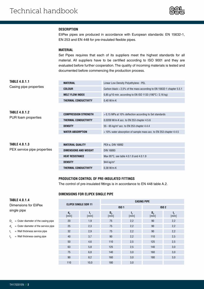
Technical handbook
TH170201EN /// 2
ELIPEX SINGLE SDR 11CASING PIPE
ISO 1 ISO 2
dO [mm]
t1 [mm]
DO [mm]
t2 [mm]
DO [mm]
t2 [mm]
20 1,9 75 2,2 90 2,2
25 2,3 75 2,2 90 2,2
32 2,9 75 2,2 90 2,2
40 3,7 90 2,2 110 2,5
50 4,6 110 2,5 125 2,5
63 5,8 125 2,5 140 3,0
75 6,8 140 3,0 160 3,0
90 8,2 160 3,0 180 3,0
110 10,0 180 3,0
TABLE 4.0.1.4Dimensions for EliPex
single pipe
Do = Outer diameter of the casing pipe
do = Outer diameter of the service pipe
t1 = Wall thickness service pipe
t2 = Wall thickness casing pipe
MATERIAL QUALITY PEX-a, DIN 16892
DIMENSIONS AND WEIGHT DIN 16893
HEAT RESISTANCE Max 95°C, see table 4.0.1.8 and 4.0.1.9
DENSITY 944 kg/m3
THERMAL CONDUCTIVITY 0,38 W/m·K
TABLE 4.0.1.3PEX service pipe properties
PRODUCTION CONTROL OF PRE-INSULATED FITTINGSThe control of pre-insulated fittings is in accordance to EN 448 table A.2.
MATERIAL Linear Low Density Polyethylene - PEL
COLOUR Carbon black > 2,5% of the mass according to EN 15632-1 chapter 5.5.1
MELT FLOW INDEX 0,85 g/10 min. according to EN ISO 1133 (190°C / 2,16 kg)
THERMAL CONDUCTIVITY 0,40 W/m·K
COMPRESSION STRENGTH > 0,15 MPa at 10% deflection according to Set standards
THERMAL CONDUCTIVITY 0,0209 W/m·K acc. to EN 253 chapter 4.5.6
DENSITY 55 - 65 kg/m3 acc. to EN 253 chapter 4.4.4
WATER ABSORPTION < 10% water absorption of sample mass acc. to EN 253 chapter 4.4.5
TABLE 4.0.1.1Casing pipe properties
TABLE 4.0.1.2PUR foam properties
DIMENSIONS FOR ELIPEX SINGLE PIPE
DESCRIPTION EliPex pipes are produced in accordance with European standards: EN 15632-1,
EN 253 and EN 448 for pre-insulated flexible pipes.
MATERIAL Set Pipes requires that each of its suppliers meet the highest standards for all
material. All suppliers have to be certified according to ISO 9001 and they are
evaluated before further cooperation. The quality of incoming materials is tested and
documented before commencing the production process.

Technical handbook
TH170201EN /// 3
ELIPEX DOUBLE PIPE SDR 11CASING PIPE
ISO 1 ISO 2
dO [mm]
t1 [mm]
DO [mm]
t2 [mm]
DO [mm]
t2 [mm]
20-20 1,9 90 2,2 110 2,2
25-25 2,3 90 2,2 110 2,5
32-32 2,9 110 2,5 125 2,5
40-40 3,7 125 2,5 140 3,0
50-50 4,6 160 3,0 180 3,0
63-63 5,8 180 3,0
ELIPEX DOUBLE PIPE SDR 7,4 CASING PIPE
ISO 1
dO [mm]
t1 [mm]
DO [mm]
t2 [mm]
25-20 3,5 90 2,2
32-20 4,4 110 2,5
40-25 5,5 125 2,5
50-32 6,9 140 3,0
63-40 8,6 160 3,0
TABLE 4.0.1.6Dimensions for EliPex double
pipe SDR 11
Do = Outer diameter of the casing pipe
do = Outer diameter of the service pipe
t1 = Wall thickness service pipe
t2 = Wall thickness casing pipe
TABLE 4.0.1.7Dimensions for EliPex double
pipe SDR 7,4
Do = Outer diameter of the casing pipe
do = Outer diameter of the service pipe
t1 = Wall thickness service pipe
t2 = Wall thickness casing pipe
DIMENSIONS FOR ELIPEX DOUBLE PIPE
ELIPEX SINGLE SDR 7,4 CASING PIPE
ISO 1 ISO 2
dO [mm]
t1 [mm]
DO [mm]
t2 [mm]
DO [mm]
t2 [mm]
20 2,8 75 2,2 90 2,2
25 3,5 75 2,2 90 2,2
32 4,4 75 2,2 90 2,2
40 5,5 90 2,2 110 2,5
50 6,9 110 2,5 125 2,5
63 8,6 125 2,5 140 3,0
TABLE 4.0.1.5Dimensions for EliPex single
pipe SDR 7,4
Do = Outer diameter of the casing pipe
do = Outer diameter of the service pipe
t1 = Wall thickness service pipe
t2 = Wall thickness casing pipe

Technical handbook
TH170201EN /// 4
OPERATING TEMPERATURE
[°C]
MAXIMUM OPERATING PRESSURE [BAR] FOR SDR 7,4
1 YEAR 5 YEARS 10 YEARS 25 YEARS 50 YEARS 100 YEARS
30 22,3 21,9 21,7 21,4 21,3 21,1
40 19,8 19,4 19,3 19,1 18,9 18,7
50 17,7 17,3 17,2 17,0 16,8 16,7
60 15,8 15,5 15,3 15,2 15,0
70 14,1 13,8 13,7 13,6 13,4
80 12,7 12,4 12,3 12,1
90 11,4 11,1 11,0
95 10,8 10,6
TABLE 4.0.1.9EliPex lifetime with regards to
temperature and pressure
PRODUCTION CONTROL OF ELIPEXTo ensure a high product quality the entire production of Set Pipes goes through
strict quality control. The control of pre-insulated service pipes is according to
EN 253 for district heating pipes. Furthermore, additional tests are carried and
documented before commencing the production process. Highly qualified
employees and their awareness of quality is our strength in manufacturing.
OPERATING TEMPERATURE
[°C]
MAXIMUM OPERATING PRESSURE [BAR] FOR SDR 11
1 YEAR 5 YEARS 10 YEARS 25 YEARS 50 YEARS 100 YEARS
30 14,1 13,8 13,7 13,5 13,4 13,3
40 12,5 12,3 12,2 12,0 11,9 11,8
50 11,2 11,0 10,9 10,7 10,7 10,6
60 10,0 9,8 9,7 9,6 9,5
70 8,9 8,8 8,7 8,6 8,5
80 8,0 7,8 7,7 7,6
90 7,2 7,0 6,9
95 6,8 6,6
TABLE 4.0.1.8EliPex lifetime with regards to
temperature and pressure
MAXIMUM OPERATING PRESSURE FOR ELIPEXTable 4.0.1.8 and 4.0.1.9 gives an overview of the lifetime of the EliPex district
heating pipes with regards to temperature and pressure according to DIN 16893.

Technical handbook
TH170201EN /// 5
TABLE 4.0.1.11EliPex coil dimensions for
40 feet HC container,
8 coils in each container
+ one DC coil
CASING PIPE [mm]
INNER DIAMETER [mm]
OUTER DIAMETER[mm]
WIDTH [mm]
LENGTH[m]
75 1450 ± 30 2250 ± 50 1000 ± 50 342
90 1600 ± 30 2250 ± 50 1000 ± 50 253
110 1600 ± 30 2250 ± 50 1000 ± 50 155
125 1800 ± 30 2250 ± 50 1000 ± 50 95
140 2000 ± 30 2250 ± 50 1120 ± 50 56
160 2000 ± 30 2250 ± 50 1120 ± 50 45
180 1900 ± 30 2250 ± 50 1120 ± 50 39
CASING PIPE [mm]
INNER DIAMETER[mm]
OUTER DIAMETER[mm]
WIDTH [mm]
LENGTH[m]
75 1450 ± 30 2530 ± 50 1000 ± 50 530
90 1580 ± 30 2530 ± 50 1000 ± 50 407
110 1580 ± 30 2530 ± 50 1000 ± 50 280
125 1820 ± 30 2530 ± 50 1000 ± 50 154
140 2000 ± 30 2530 ± 50 1120 ± 50 105
160 1950 ± 30 2530 ± 50 1120 ± 50 91
180 1900 ± 30 2530 ± 50 1120 ± 50 80
TABLE 4.0.1.10EliPex coil dimensions for
40 feet DC container,
11 coils in each container
COIL DIMENSIONS FOR ELIPEX EliPex pipes are delivered in coils to fit in both DC and HC containers. The
EliPex pipe length can be customized by the request of the customers and Set Pipes
can also provide longer coils. For special requests please contact our technical
department.
FIG 4.0.1.1HC container load

Technical handbook
TH170201EN /// 6
CHAPTER 4.0.2 ELICOPP
EliCopp pre-insulated flexible pipes are produced from copper service pipes,
polyurethane foam (PUR) and polyethylene casing pipe (PEL). Available in single
and double pipe coils in 15 mm to 28 mm outer diameter.
See chapter 4.9 for detailed descriptions of dimensions and sizes. Set Pipes can
offer insulation of other products not specified in our product catalogue, for special
requests please contact our technical department.
APPLICATION RANGEThis specification is made for pre-insulated EliCopp single and double pipes for
district heating. The temperature resistance of the copper pipes is higher than of
plastic pipes and therefore suitable for temperatures above 95°C.
DESCRIPTIONEliCopp pipes are produced in accordance with European standards:
EN 15632-4, EN 253.
MATERIAL Linear Low Density Polyethylene - PEL
COLOUR Carbon black > 2,5% of the mass according to EN 15632-1 chapter 5.5.1
MELT FLOW INDEX 0,85 g/10 min. according to EN ISO 1133 (190°C / 2,16 kg)
THERMAL CONDUCTIVITY 0,40 W/m·K
TABLE 4.0.2.1Casing pipe properties
MATERIALSet Pipes requires that each of its suppliers meet the highest standards for all
material. All suppliers have to be certified according to ISO 9001 and they are
evaluated before further cooperation. The quality of incoming materials is tested
and documented before commencing the production process
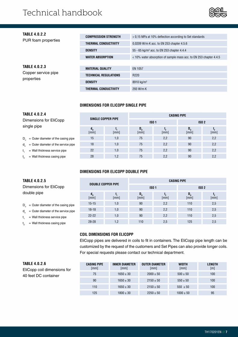
Technical handbook
TH170201EN /// 7
MATERIAL QUALITY EN 1057
TECHNICAL REGULATIONS R220
DENSITY 8910 kg/m3
THERMAL CONDUCTIVITY 293 W/m·K
TABLE 4.0.2.3Copper service pipe
properties
TABLE 4.0.2.4Dimensions for EliCopp
single pipe
Do = Outer diameter of the casing pipe
do = Outer diameter of the service pipe
t1 = Wall thickness service pipe
t2 = Wall thickness casing pipe
TABLE 4.0.2.5Dimensions for EliCopp
double pipe
Do = Outer diameter of the casing pipe
do = Outer diameter of the service pipe
t1 = Wall thickness service pipe
t2 = Wall thickness casing pipe
DIMENSIONS FOR ELICOPP SINGLE PIPE
SINGLE COPPER PIPE CASING PIPE
ISO 1 ISO 2
dO [mm]
t1 [mm]
DO [mm]
t2 [mm]
DO [mm]
t2 [mm]
15 1,0 75 2,2 90 2,2
18 1,0 75 2,2 90 2,2
22 1,0 75 2,2 90 2,2
28 1,2 75 2,2 90 2,2
DOUBLE COPPER PIPE CASING PIPE
ISO 1 ISO 2
dO [mm]
t1 [mm]
DO [mm]
t2 [mm]
DO [mm]
t2 [mm]
15-15 1,0 90 2,2 110 2,5
18-18 1,0 90 2,2 110 2,5
22-22 1,0 90 2,2 110 2,5
28-28 1,2 110 2,5 125 2,5
DIMENSIONS FOR ELICOPP DOUBLE PIPE
TABLE 4.0.2.2PUR foam properties
COMPRESSION STRENGTH > 0,15 MPa at 10% deflection according to Set standards
THERMAL CONDUCTIVITY 0,0209 W/m·K acc. to EN 253 chapter 4.5.6
DENSITY 55 - 65 kg/m3 acc. to EN 253 chapter 4.4.4
WATER ABSORPTION < 10% water absorption of sample mass acc. to EN 253 chapter 4.4.5
CASING PIPE [mm]
INNER DIAMETER[mm]
OUTER DIAMETER[mm]
WIDTH [mm]
LENGTH[m]
75 1650 ± 30 2000 ± 50 500 ± 50 100
90 1650 ± 30 2150 ± 50 550 ± 50 100
110 1650 ± 30 2150 ± 50 550 ± 50 100
125 1800 ± 30 2250 ± 50 1000 ± 50 95
TABLE 4.0.2.6EliCopp coil dimensions for
40 feet DC container
COIL DIMENSIONS FOR ELICOPP EliCopp pipes are delivered in coils to fit in containers. The EliCopp pipe length can be
customized by the request of the customers and Set Pipes can also provide longer coils.
For special requests please contact our technical department.

Technical handbook
TH170201EN /// 8
CHAPTER 4.0.3 ELISTEEL
EliSteel pre-insulated flexible pipes are produced from steel, polyurethane foam
(PUR) and polyethylene casing pipe (PEL). Available in single and double pipe coils,
in 20 mm to 28 mm outer diameter. See chapter 4.9 for detailed descriptions of
dimensions and sizes. Set Pipes can offer insulation of other products not specified in
our product catalogue, for special requests please contact our technical department.
APPLICATION RANGEThis specification is made for pre-insulated EliSteel single and double pipes for
district heating. The temperature resistance of the steel pipes is higher than of plastic
pipes and therefore suitable for temperatures above 95°C.
DESCRIPTIONEliSteel pipes are produced in accordance with European standards:
EN 15632-4, and EN 253.
MATERIALSet Pipes requires that each of its suppliers meet the highest standards for all
material. All suppliers have to be certified according to ISO 9001 and they are
evaluated before further cooperation. The quality of incoming materials is tested
and documented before commencing the production process
MATERIAL Linear Low Density Polyethylene – PEL
COLOUR Carbon black > 2,5% of the mass according to EN 15632-1 chapter 5.5.1
MELT FLOW INDEX 0,85 g/10 min. according to EN ISO 1133 (190°C / 2,16 kg)
THERMAL CONDUCTIVITY 0,40 W/m·K
TABLE 4.0.3.1Casing pipe properties

Technical handbook
TH170201EN /// 9
PRODUCTION CONTROL OF PRE-INSULATED FITTINGSThe control of pre-insulated fittings is in accordance to EN 448 table A.2.
DIMENSIONS FOR ELISTEEL SINGLE PIPE
TABLE 4.0.3.4Dimensions for EliSteel
single pipe
Do = Outer diameter of the casing pipe
do = Outer diameter of the service pipe
t1 = Wall thickness service pipe
t2 = Wall thickness casing pipe
ELISTEEL SINGLE PIPECASING PIPE
ISO 1 ISO 2
dO [mm]
t1 [mm]
DO [mm]
t2 [mm]
DO [mm]
t2 [mm]
20 2,0 75 2,2 90 2,2
25 2,0 75 2,2 90 2,2
28 2,0 75 2,2 90 2,2
TABLE 4.0.3.5Dimensions for Elisteel
double pipe
Do = Outer diameter of the casing pipe
do = Outer diameter of the service pipe
t1 = Wall thickness service pipe
t2 = Wall thickness casing pipe
ELISTEEL DOUBLE PIPECASING PIPE
ISO 1 ISO 2
dO [mm]
t1 [mm]
DO [mm]
t2 [mm]
DO [mm]
t2 [mm]
20-20 2,0 90 2,2 110 2,5
25-25 2,0 90 2,2 110 2,5
28-28 2,0 110 2,5 125 2,5
DIMENSIONS FOR ELISTEEL DOUBLE PIPE
COMPRESSION STRENGTH > 0,15 MPa at 10% deflection according to Set standards
THERMAL CONDUCTIVITY 0,0209 W/m·K acc. to EN 253 chapter 4.5.6
DENSITY 55 - 65 kg/m3 acc. to EN 253 chapter 4.4.4
WATER ABSORPTION < 10% water absorption of sample mass acc. to EN 253 chapter 4.4.5
MATERIAL QUALITY EN 10217-1
TECHNICAL REGULATIONS P195
DENSITY 7850 kg/m3
THERMAL CONDUCTIVITY 50,0 W/m·K
TABLE 4.0.3.3Steel service pipe properties
TABLE 4.0.3.2PUR foam properties
CASING PIPE [mm]
INNER DIAMETER[mm]
OUTER DIAMETER[mm]
WIDTH [mm]
LENGTH[m]
75 1700 ± 30 2200 ± 50 450 ± 50 100
90 1700 ± 30 2200 ± 50 550 ± 50 100
110 1800 ± 30 2200 ± 50 940 ± 50 100
125 1830 ± 30 2250 ± 50 1000 ± 50 95
TABLE 4.0.3.6EliSteel coil dimensions
for 40 feet DC container
COIL DIMENSIONS FOR ELISTEEL EliSteel pipes are delivered in coils to fit in DC containers. The EliSteel pipe length
can be customized by the request of the customers and Set Pipes can also provide
longer coils. For special requests please contact our technical department.

Technical handbook
TH170201EN /// 10
CHAPTER 4.0.4 ELIALPEX
EliAlpex pre-insulated flexible pipes are produced from AlPex, polyurethane foam
(PUR) and PEL casing pipe. Available in single and double pipe coils in 20 mm to
40 mm outer diameter. See chapter 4.9 for detailed descriptions of dimensions and
sizes. Set Pipes can offer insulation of other products not specified in our product
catalogue, for special requests please contact our technical department.
MATERIAL Linear Low Density Polyethylene - PEL
COLOUR Carbon black > 2,5% of the mass according to EN 15632-1 chapter 5.5.1
MELT FLOW INDEX 0,85 g/10 min. according to EN ISO 1133 (190°C / 2,16 kg)
THERMAL CONDUCTIVITY 0,40 W/m·K
TABLE 4.0.4.1PUR foam properties
APPLICATION RANGEThis specification is made for pre-insulated EliAlpex single and double pipes for
district heating. The aluminium layer in the EliAlpex pipes has full oxygen barrier
diffusion.
DESCRIPTIONEliAlpex pipes are produced in accordance with European standards:
EN 15632-1 and EN 253.
COMPRESSION STRENGTH > 0,15 MPa at 10% deflection according to Set standards
THERMAL CONDUCTIVITY 0,0209 W/m·K acc. to EN 253 chapter 4.5.6
DENSITY 55 - 65 kg/m3 acc. to EN 253 chapter 4.4.4
WATER ABSORPTION < 10% water absorption of sample mass acc. to EN 253 chapter 4.4.5
TABLE 4.0.4.2Aluminium service pipe
properties
MATERIAL Set Pipes requires that each of its suppliers meet the highest standards for all
material. All suppliers have to be certified according to ISO 9001 and they are
evaluated before further cooperation. The quality of incoming materials is tested
and documented before commencing the production process.

Technical handbook
TH170201EN /// 11
MATERIAL QUALITY DIN 16892
DIMENSIONS AND WEIGHT DIN 16893
OXYGEN BARRIER Oxygen diffusion 0% acc. to DIN 4726
DENSITY 944 kg/m3
THERMAL CONDUCTIVITY 0,43 W/m·K
TABLE 4.0.4.3Aluminium service pipe
properties
TABLE 4.0.4.4Dimensions for EliAlpex
single pipe
Do = Outer diameter of the casing pipe
do = Outer diameter of the service pipe
t1 = Wall thickness service pipe
t2 = Wall thickness casing pipe
ELIALPEX SINGLE PIPE SDR 7,4CASING PIPE
ISO 1 ISO 2
dO [mm]
t1 [mm]
DO [mm]
t2 [mm]
DO [mm]
t2 [mm]
20 2,9 75 2,2 90 2,2
25 3,7 75 2,2 90 2,2
32 4,7 75 2,2 90 2,2
40 5,4 90 2,2 110 2,5
TABLE 4.0.4.5Dimensions for EliAlpex
double pipe
Do = Outer diameter of the casing pipe
do = Outer diameter of the service pipe
t1 = Wall thickness service pipe
t2 = Wall thickness casing pipe
ELIALPEX DOUBLE PIPE SDR 7,4CASING PIPE
ISO 1 ISO 2
dO [mm]
t1 [mm]
DO [mm]
t2 [mm]
DO [mm]
t2 [mm]
20-20 14,2 90 2,2 110 2,5
25-25 17,6 90 2,2 110 2,2
32-32 22,6 110 2,5 125 2,5
40-40 29,2 125 2,5 140 3,0
DIMENSIONS FOR ELIALPEX DOUBLE PIPE
DIMENSIONS FOR ELIALPEX SINGLE PIPE
CASING PIPE [mm]
INNER DIAMETER[mm]
OUTER DIAMETER[mm]
WIDTH [mm]
LENGTH[m]
75 1700 ± 30 2200 ± 50 450 ± 50 100
90 1700 ± 30 2200 ± 50 550 ± 50 100
110 1800 ± 30 2200 ± 50 940 ± 50 100
125 1830 ± 30 2250 ± 50 1000 ± 50 95
TABLE 4.0.4.6EliAlpex coil dimensions for
40 feet DC container
COIL DIMENSIONS FOR ELIALPEX EliAlpex pipes are delivered in coils to fit in DC containers. The EliAlpex pipe length can
be customized by the request of the customers and Set Pipes can also provide longer
coils. For special requests please contact our technical department.

Technical handbook
TH170201EN /// 12
CHAPTER 4.1 APPLICATION RANGE
CHAPTER 4.1.1 HEAT DEMAND
To define the pipe dimension of the district heating system the following must
be taken into consideration; heating, drinking water, snow melting and other uses.
The pipe diameter is determined by the sum of the previously mentioned usage.
In the case of heating, the following equation can be used:
THUS: = Mass flow [m3/s]
Q = Thermal requirement [W]
w = Water density (978 kg/m3 við 70°C)
cp = Specific heat for water (4191 J/kg·K við 70°C)
ΔT = Temperature change between forward and return flow media (TVL – TRL) [K]
EXAMPLE: A house has the thermal requirement about 14 kW and temperature
change between flow and return flow media is 40°C. If we estimate the specific
heat and density for 70°C water then we can find the water demand for the house:

Technical handbook
TH170201EN /// 13
CHAPTER 4.1.2 TOTAL PRESSURE LOSS FOR PRE – INSULATED FLEXIBLE PIPES
After the water demand has been determined it is possible to calculate the pressure
loss for a selected pipe dimension. Network length, height difference, the number
of connections and branches have an influence on the pressure loss. The
pressure loss in the pipes should be in the range of 100 – 200 Pa/m. Pressure loss
requirements can vary depending on the system, for example a system with a high
pressure can lead to increased operating costs. To calculate the pressure loss for
each pipe dimension the following equation can be used:
THUS: f = Friction factor [-]
L = Length of the pipe [m]
di = Inner diameter of the service pipe [m]
V = Average water velocity [m/s]
w = Water density (972 kg/m3 við 80°C)
Hm = Height difference [m]
g = Acceleration due to gravity
The friction factor is found with the following equation:
THUS:k = Resistance Coefficients for service pipes:
Steel = 100 μm
Pex and Alpex = 7,0 μm
Copper = 1,9 μm
Re = Reynolds number for flow in a circular pipe
Pipe
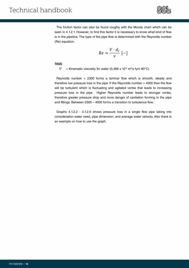
Technical handbook
TH170201EN /// 14
The friction factor can also be found roughly with the Moody chart which can be
seen in 4.1.2.1. However, to find this factor it is necessary to know what kind of flow
is in the pipeline. The type of the pipe flow is determined with the Reynolds number
(Re) equation:
THUS: = Kinematic viscosity for water (0,366 x 10-6 m2/s fyrir 80°C)
Reynolds number < 2300 forms a laminar flow which is smooth, steady and
therefore low pressure loss in the pipe. If the Reynolds number > 4000 then the flow
will be turbulent which is fluctuating and agitated vortex that leads to increasing
pressure loss in the pipe. Higher Reynolds number leads to stronger vortex,
therefore greater pressure drop and more danger of cavitation forming in the pipe
and fittings. Between 2300 – 4000 forms a transition to turbulence flow.
Graphs 4.1.2.2 - 4.1.2.6 shows pressure loss in a single flow pipe taking into
consideration water need, pipe dimension, and average water velocity. Also there is
an example on how to use the graph.

Technical handbook
TH170201EN /// 15
GRAPH 4.1.2.1 – MOODY CHART
103
104
105
106
107
108
10−2
10−1 89
1.2
1.4
1.6
1.82
2.53
3.54
4.55
5.56789
67
82
34
56
78
23
45
67
82
34
56
78
23
45
67
82
34
56
78
1e−0
05
2e−0
05
5e−0
05
0.00
01
0.00
02
0.00
04
0.00
06
0.00
080.
001
0.00
15
0.00
2
0.00
3
0.00
4
0.00
6
0.00
8
0.01
0.01
250.
015
0.01
750.
02
0.02
5
0.03
0.03
5
0.04
0.04
50.
05
0.06
0.07
Lam
inar
flow
Crit
ical
zone
Tra
nsiti
on z
one
Com
plet
e tu
rbul
ence
, rou
gh p
ipes
, R >
350
0/r,
1/√
f =
1.14
− 2
log
r
Darcy−Weisbach friction factor f
Mo
od
y D
iag
ram
Mat
eria
l
Riv
eted
ste
elC
oncr
ete
Woo
d st
ave
Cas
t iro
nG
alva
nize
d iro
nA
spha
lted
cast
iron
Com
mer
cial
ste
elD
raw
n tu
bing
Rey
nold
s nu
mbe
rR
(V
in m
/s, D
in m
, ν in
m 2/s
)V
D ν
Relative roughness r (ε in mm, D in mm)εD
VD
for w
ater
at 2
0°C
(V
in m
/s, D
in c
m)
0.06 |
|0.
1 |0.
2 |0.
4 |0.
6 |0.
8 |1 |
2 |4 |
6 |8 |
10 |20 |
40 |60 |
|10
0 |20
0 |40
0 |60
0 ||
1000 |
2000 |
4000 |
6000 |
|10
000
|__
____
____
____
____
____
____
____
____
____
____
____
____
____
____
____
____
____
____
____
____
____
____
____
____
____
____
____
____
____
____
____
____
____
____
____
____
____
____
____
____
____
____
____
____
____
____
____
____
__
VD
for a
tmos
pher
ic a
ir at
20°
C1 |
2 |4 |
6 |8 |
10 |20 |
40 |60 |
|10
0 |20
0 |40
0 |60
0 ||
1000 |
2000 |
4000 |
6000 |
|10
000
|20
000
|40
000
|60
000
||10
0000
|
ε (m
m)
0.9−
90.
3−3
0.18
−0.9
0.25
0.15
0.12
0.04
60.
0015
Flui
d at
20°
C
Wat
erAi
r (10
1.32
5 kP
a)
ν (m
2 /s)
1.00
3e−0
061.
511e
−005

Technical handbook
TH170201EN /// 16
AN EXAMPLE HOW TO USE THE PRESSURE DROP GRAPH A residential area has a water demand of about 1,6 l/s. To determine what pipe dimension is suitable, the general
rule for a suitable pressure loss in water pipes is between 100 – 150 Pa/m. In this example it is determined that
100 Pa/m results in an average water speed in the pipeline of about 0,75 m/s and the recommended pipe
dimension would be Ø63mm.

Technical handbook
TH170201EN /// 17
GRAPH 4.1.2.2 – PRESSURE LOSS IN ELIPEX SDR 11 SERVICE PIPE
Ø2016,2 mm
Ø2520,4 mm
Ø3226,2 mm
Ø4032,6 mm
Ø5040,8 mm
Ø6351,4 mm
Ø7561,4 mm
Ø90 73,6 mm
Ø11090,0 mm
0,0
0,1
1,0
10,0
100,0
10 100 1.000
[l/s]
[Pa/m]

Technical handbook
TH170201EN /// 18
GRAPH 4.1.2.3 - – PRESSURE LOSS IN SDR 7,4 SERVICE PIPE
Ø2014,4 mm
Ø2518,0 mm
Ø3223,2 mm
Ø4029,0 mm
Ø5036,2 mm
Ø6345,8 mm
0,0
0,1
1,0
10,0
10 100 1.000
[l/s]
[Pa/m]

Technical handbook
TH170201EN /// 19
GRAPH 4.1.2.4 - PRESSURE LOSS IN ELICOPP SERVICE PIPE
Ø1513,0 mm
Ø1816,0 mm
Ø2220,0 mm
Ø2825,6 mm
0,0
0,1
1,0
10 100 1.000
[l/s]
[Pa/m]

Technical handbook
TH170201EN /// 20
GRAPH 4.1.2.5 - PRESSURE LOSS IN ELISTEEL SERVICE PIPE
Ø2016 mm
Ø2521 mm
Ø28 24 mm
0,0
0,1
1,0
10 100 1.000
[l/s]
[Pa/m]

Technical handbook
TH170201EN /// 21
GRAPH 4.1.2.6 - PRESSURE LOSS IN ELIALPEX SERVICE PIPE
Ø2014,2 mm
Ø2517,6 mm
Ø3222,6 mm
Ø4029,2 mm
0,0
0,1
1,0
10,0
10 100 1.000
[l/s]
[Pa/m]

Technical handbook
TH170201EN /// 22
CHAPTER 4.1.3 HEAT LOSS – PRE- INSULATED FLEXIBLE PIPES
One of the most important characteristics of district heating systems is their heat
retention. As most district heating stations in Europe have to burn gas, oil, biomass
or waste, good insulation and proper ground work is necessary. Set Pipes works
continuously to improve foam insulation in close cooperation with its suppliers to help
improve energy efficiency and reduce CO2 emission.
All results in the following tables are calculated according to EN 13941.
To calculate the total heat loss per meter of buried pipe it is necessary to know
the average water temperature and the overall heat loss coefficient for the pipe line
system. The average temperature for the water is calculated with the following
equation:
THUS: TVL = Forward flow media temperature [°C]
TRL = Return flow media temperature [°C]
TE = Soil temperature [°C]
EXAMPLE: We know the temperature for the forward flow media to be 80°C and
for the return flow media to be 60°C. We estimate the soil temperature to be
10°C. Thus we can calculate the average temperature of the water:
The calculation shows an average temperature of TM 60 K.

Technical handbook
TH170201EN /// 23
THERMAL RESISTANCE OF THE SERVICE PIPE
Pre-insulated flexible pipes are made up of three components, casing pipe,
PUR insulation foam and pipes. All of these materials have variable heat loss (q).
The following equation is used to calculate the thermal resistance (R) for each
material which is then used to calculate overall heat loss coefficient (Upipe in groUnd
).
THUS: P = Coefficient of thermal conductivity for the service pipe:
PEX = 0,380 W/m·K
AlPex = 0,430 W/m·K
Steel = 50,0 W/m·K
Copper = 263 W/m·K
da = Outer diameter service pipe [m]
di = Inner diameter service pipe [m]
THERMAL RESISTANCE OF THE INSULATION MATERIAL
THUS: PUR = Coefficient of thermal conductivity for the PUR insulation in flexible pipes
= 0,0209 W/m·K
DPUR = Outer diameter of the insulation material [m]
da = Outer diameter of the service pipe [m]
THERMAL RESISTANCE OF THE CASING PIPE
THUS: PE100 = Coefficient of thermal conductivity for the casing pipe = 0,400 W/m·K)
DO = Outer diameter of the casing pipe [m]
Di = Inner diameter of the casing pipe [m]
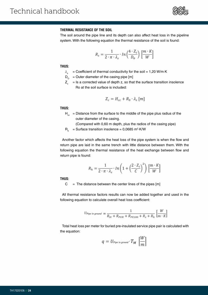
Technical handbook
TH170201EN /// 24
THERMAL RESISTANCE OF THE SOILThe soil around the pipe line and its depth can also affect heat loss in the pipeline
system. With the following equation the thermal resistance of the soil is found:
THUS: s = Coefficient of thermal conductivity for the soil = 1,20 W/m·K
DO = Outer diameter of the casing pipe [m]
Zc = Is a corrected value of depth z, so that the surface transition insolence
Ro at the soil surface is included:
THUS: Hcc = Distance from the surface to the middle of the pipe plus radius of the
outer diameter of the casing.
(Compared with 0,60 m depth, plus the radios of the casing pipe)
R0 = Surface transition insolence = 0,0685 m2·K/W
Another factor which affects the heat loss of the pipe system is when the flow and
return pipe are laid in the same trench with little distance between them. With the
following equation the thermal resistance of the heat exchange between flow and
return pipe is found:
THUS: C = The distance between the center lines of the pipes [m]
All thermal resistance factors results can now be added together and used in the
following equation to calculate overall heat loss coefficient:
Total heat loss per meter for buried pre-insulated service pipe pair is calculated with
the equation:
Pipe in ground
Pipe in ground
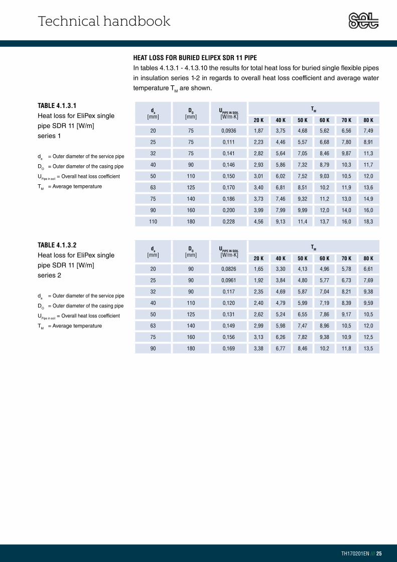
Technical handbook
TH170201EN /// 25
HEAT LOSS FOR BURIED ELIPEX SDR 11 PIPEIn tables 4.1.3.1 - 4.1.3.10 the results for total heat loss for buried single flexible pipes
in insulation series 1-2 in regards to overall heat loss coefficient and average water
temperature TM are shown.
da[mm]
DO[mm]
UPIPE IN SOIL [W/m·K]
TM
20 K 40 K 50 K 60 K 70 K 80 K
20 75 0,0936 1,87 3,75 4,68 5,62 6,56 7,49
25 75 0,111 2,23 4,46 5,57 6,68 7,80 8,91
32 75 0,141 2,82 5,64 7,05 8,46 9,87 11,3
40 90 0,146 2,93 5,86 7,32 8,79 10,3 11,7
50 110 0,150 3,01 6,02 7,52 9,03 10,5 12,0
63 125 0,170 3,40 6,81 8,51 10,2 11,9 13,6
75 140 0,186 3,73 7,46 9,32 11,2 13,0 14,9
90 160 0,200 3,99 7,99 9,99 12,0 14,0 16,0
110 180 0,228 4,56 9,13 11,4 13,7 16,0 18,3
da[mm]
DO[mm]
UPIPE IN SOIL [W/m·K]
TM
20 K 40 K 50 K 60 K 70 K 80 K
20 90 0,0826 1,65 3,30 4,13 4,96 5,78 6,61
25 90 0,0961 1,92 3,84 4,80 5,77 6,73 7,69
32 90 0,117 2,35 4,69 5,87 7,04 8,21 9,38
40 110 0,120 2,40 4,79 5,99 7,19 8,39 9,59
50 125 0,131 2,62 5,24 6,55 7,86 9,17 10,5
63 140 0,149 2,99 5,98 7,47 8,96 10,5 12,0
75 160 0,156 3,13 6,26 7,82 9,38 10,9 12,5
90 180 0,169 3,38 6,77 8,46 10,2 11,8 13,5
TABLE 4.1.3.1Heat loss for EliPex single
pipe SDR 11 [W/m]
series 1
da = Outer diameter of the service pipe
DO = Outer diameter of the casing pipe
UPipe in soil = Overall heat loss coefficient
TM = Average temperature
TABLE 4.1.3.2Heat loss for EliPex single
pipe SDR 11 [W/m]
series 2
da = Outer diameter of the service pipe
DO = Outer diameter of the casing pipe
UPipe in soil = Overall heat loss coefficient
TM = Average temperature

Technical handbook
TH170201EN /// 26
TABLE 4.1.3.3Heat loss for EliPex single
pipe SDR 7,4 [W/m] series 1
da = Outer diameter of the service pipe
DO = Outer diameter of the casing pipe
UPipe in soil = Overall heat loss coefficient
TM = Average temperature
TABLE 4.1.3.4Heat loss for EliPex single
pipe SDR 7,4 [W/m] series 2
da = Outer diameter of the service pipe
DO = Outer diameter of the casing pipe
UPipe in soil = Overall heat loss coefficient
TM = Average temperature
HEAT LOSS FOR BURIED ELIPEX SINGLE SDR 7,4 PIPE
HEAT LOSS FOR BURIED ELISTEEL SINGLE PIPE
TABLE 4.1.3.5Heat loss for EliSteel single
pipe [W/m] series 1
da = Outer diameter of the service pipe
DO = Outer diameter of the casing pipe
UPipe in soil = Overall heat loss coefficient
TM = Average temperature
TABLE 4.1.3.6Heat loss for EliSteel single
pipe [W/m] series 2
da = Outer diameter of the service pipe
DO = Outer diameter of the casing pipe
UPipe in soil = Overall heat loss coefficient
TM = Average temperature
da[mm]
DO[mm]
UPIPE IN SOIL [W/m·K]
TM
20 K 40 K 50 K 60 K 70 K 80 K
20 75 0,0932 1,86 3,73 4,66 5,59 6,53 7,46
25 75 0,111 2,22 4,43 5,54 6,65 7,75 8,86
32 75 0,140 2,80 5,60 7,00 8,40 9,80 11,2
40 90 0,145 2,91 5,82 7,27 8,72 10,2 11,6
50 110 0,149 2,99 5,97 7,47 8,96 10,5 11,9
63 125 0,169 3,38 6,75 8,44 10,1 11,8 13,5
da[mm]
DO[mm]
UPIPE IN SOIL [W/m·K]
TM
20 K 40 K 50 K 60 K 70 K 80 K
20 90 0,0822 1,64 3,29 4,11 4,93 5,76 6,58
25 90 0,0956 1,91 3,82 4,78 5,74 6,69 7,65
32 90 0,117 2,33 4,66 5,83 7,00 8,16 9,33
40 110 0,119 2,38 4,77 5,96 7,15 8,34 9,53
50 125 0,130 2,60 5,21 6,51 7,81 9,11 10,4
63 140 0,148 2,97 5,93 7,42 8,90 10,4 11,9
da[mm]
DO[mm]
UPIPE IN SOIL [W/m·K]
TM
20 K 40 K 50 K 60 K 70 K 80 K
20 75 0,0944 1,89 3,78 4,72 5,67 6,61 7,55
25 75 0,112 2,25 4,50 5,62 6,75 7,87 9,00
28 75 0,125 2,49 4,98 6,23 7,47 8,72 9,96
da[mm]
DO[mm]
UPIPE IN SOIL [W/m·K]
TM
20 K 40 K 50 K 60 K 70 K 80 K
20 90 0,0832 1,66 3,33 4,16 4,99 5,82 6,65
25 90 0,0969 1,94 3,88 4,84 5,81 6,78 7,75
28 90 0,106 2,11 4,23 5,29 6,34 7,40 8,46

Technical handbook
TH170201EN /// 27
HEAT LOSS FOR BURIED ELICOPP SINGLE PIPE
TABLE 4.1.3.7Heat loss for EliCopp single
pipe [W/m] series 1
da = Outer diameter of the service pipe
DO = Outer diameter of the casing pipe
UPipe in soil = Overall heat loss coefficient
TM = Average temperature
TABLE 4.1.3.8Heat loss for EliCopp single
pipe [W/m] series 2
da = Outer diameter of the service pipe
DO = Outer diameter of the casing pipe
UPipe in soil = Overall heat loss coefficient
TM = Average temperature
HEAT LOSS FOR A BURIED ELIALPEX SINGLE PIPE
TABLE 4.1.3.9Heat loss for EliAlpex single
pipe [W/m] series 1
da = Outer diameter of the service pipe
DO = Outer diameter of the casing pipe
UPipe in soil = Overall heat loss coefficient
TM = Average temperature
TABLE 4.1.3.10Heat loss for EliAlpex single
[W/m] series 2
da = Outer diameter of the service pipe
DO = Outer diameter of the casing pipe
UPipe in soil = Overall heat loss coefficient
TM = Average temperature
da[mm]
DO[mm]
UPIPE IN SOIL [W/m·K]
TM
20 K 40 K 50 K 60 K 70 K 80 K
15 75 0,0782 1,56 3,13 3,91 4,69 5,48 6,26
18 75 0,0878 1,76 3,51 4,39 5,27 6,14 7,02
22 75 0,101 2,03 4,05 5,07 6,08 7,10 8,11
28 75 0,125 2,49 4,98 6,23 7,47 8,72 9,97
da[mm]
DO[mm]
UPIPE IN SOIL [W/m·K]
TM
20 K 40 K 50 K 60 K 70 K 80 K
20 75 0,0933 1,87 3,73 4,67 5,60 6,53 7,46
25 75 0,111 2,22 4,43 5,54 6,65 7,76 8,87
32 75 0,140 2,80 5,60 7,00 8,40 9,80 11,2
40 90 0,146 2,92 5,83 7,29 8,75 10,2 11,7
da[mm]
DO[mm]
UPIPE IN SOIL [W/m·K]
TM
20 K 40 K 50 K 60 K 70 K 80 K
15 90 0,0704 1,41 2,81 3,52 4,22 4,93 5,63
18 90 0,0780 1,56 3,12 3,90 4,68 5,46 6,24
22 90 0,089 1,77 3,54 4,43 5,31 6,20 7,08
28 90 0,106 2,11 4,23 5,29 6,34 7,40 8,46
da[mm]
DO[mm]
UPIPE IN SOIL [W/m·K]
TM
20 K 40 K 50 K 60 K 70 K 80 K
20 90 0,0823 1,65 3,29 4,12 4,94 5,76 6,59
25 90 0,0957 1,91 3,83 4,78 5,74 6,70 7,65
32 90 0,117 2,33 4,67 5,83 7,00 8,17 9,33
40 110 0,119 2,39 4,78 5,97 7,16 8,36 9,55

Technical handbook
TH170201EN /// 28
Total heat loss in double pipes is basically calculated as in single pipes according to
EN 13941. TM is used as previously described in 4.1.3.
TABLE 4.1.3.11Heat loss for EliPex double
pipe SDR 11 [W/m] series 1
da = Outer diameter of the service pipe
DO = Outer diameter of the casing pipe
UPipe in soil = Overall heat loss coefficient
TM = Average temperature
TABLE 4.1.3.12Heat loss for EliPex double
pipe SDR 11 [W/m] series 2
da = Outer diameter of the service pipe
DO = Outer diameter of the casing pipe
UPipe in soil = Overall heat loss coefficient
TM = Average temperature
TABLE 4.1.3.13Heat loss for EliPex double
pipe SDR 7,4 [W/m] series 1
da = Outer diameter of the service pipe
DO = Outer diameter of the casing pipe
UPipe in soil = Overall heat loss coefficient
TM = Average temperature
HEAT LOSS FOR BURIED ELIPEX SDR 11 DOUBLE PIPE
HEAT LOSS FOR BURIED ELIPEX SDR 7,4 DOUBLE PIPE
da[mm]
DO[mm]
UPIPE IN SOIL [W/m·K]
TM
20 K 40 K 50 K 60 K 70 K 80 K
20-20 90 0,160 3,20 6,40 8,60 9,60 11,2 12,8
25-25 90 0,213 4,26 8,51 11,7 12,8 14,9 17,0
32-32 110 0,213 4,26 8,51 11,7 12,8 14,9 17,0
40-40 125 0,242 4,84 9,68 13,4 14,5 16,9 19,4
50-50 160 0,220 4,39 8,78 12,0 13,2 15,4 17,6
63-63 180 0,268 5,35 10,7 14,8 16,1 18,7 21,4
da[mm]
DO[mm]
UPIPE IN SOIL [W/m·K]
TM
20 K 40 K 50 K 60 K 70 K 80 K
20-20 110 0,127 2,54 5,07 6,34 7,61 8,88 10,1
25-25 110 0,155 3,10 6,20 7,75 9,31 10,9 12,4
32-32 125 0,172 3,44 6,88 8,60 10,3 12,0 13,8
40-40 140 0,194 3,88 7,76 9,70 11,6 13,6 15,5
50-50 180 0,178 3,56 7,12 8,89 10,7 12,5 14,2
da[mm]
DO[mm]
UPIPE IN SOIL [W/m·K]
TM
20 K 40 K 50 K 60 K 70 K 80 K
25-20 90 0,213 4,256 8,51 10,6 12,8 14,9 17,0
32-20 110 0,213 4,257 8,51 10,6 12,8 14,9 17,0
40-25 125 0,242 4,838 9,68 12,1 14,5 16,9 19,4
50-32 140 0,306 6,117 12,2 15,3 18,3 21,4 24,5
63-40 160 0,400 7,992 16,0 20,0 24,0 28,0 32,0

Technical handbook
TH170201EN /// 29
TABLE 4.1.3.14Heat loss for EliSteel double
pipe [W/m] series 1
da = Outer diameter of the service pipe
DO = Outer diameter of the casing pipe
UPipe in soil = Overall heat loss coefficient
TM = Average temperature
TABLE 4.1.3.16Heat loss for EliCopp double
pipe [W/m] series 1
da = Outer diameter of the service pipe
DO = Outer diameter of the casing pipe
UPipe in soil = Overall heat loss coefficient
TM = Average temperature
TABLE 4.1.3.15Heat loss for EliSteel double
pipe [W/m] series 2
da = Outer diameter of the service pipe
DO = Outer diameter of the casing pipe
UPipe in soil = Overall heat loss coefficient
TM = Average temperature
TABLE 4.1.3.17Heat loss for EliCopp double
pipe [W/m] series 2
da = Outer diameter of the service pipe
DO = Outer diameter of the casing pipe
UPipe in soil = Overall heat loss coefficient
TM = Average temperature
HEAT LOSS FOR BURIED ELISTEEL DOUBLE PIPE
HEAT LOSS FOR BURIED ELICOPP DOUBLE PIPE
da[mm]
DO[mm]
UPIPE IN SOIL [W/m·K]
TM
20 K 40 K 50 K 60 K 70 K 80 K
20-20 90 0,160 3,20 6,40 8,60 9,60 11,2 12,8
25-25 90 0,213 4,26 8,51 10,6 12,8 14,9 17,0
28-28 110 0,176 3,53 7,05 8,82 10,6 12,3 14,1
da[mm]
DO[mm]
UPIPE IN SOIL [W/m·K]
TM
20 K 40 K 50 K 60 K 70 K 80 K
15-15 90 0,124 2,49 4,98 6,58 7,47 8,71 9,95
18-18 90 0,144 2,89 5,78 7,70 8,66 10,1 11,6
22-22 90 0,178 3,56 7,13 9,66 10,7 12,5 14,3
28-28 110 0,176 3,53 7,05 9,51 10,6 12,3 14,1
da[mm]
DO[mm]
UPIPE IN SOIL [W/m·K]
TM
20 K 40 K 50 K 60 K 70 K 80 K
20-20 110 0,127 2,54 5,07 6,34 7,61 8,88 10,1
25-25 110 0,155 3,10 6,20 7,75 9,31 10,9 12,4
28-28 125 0,149 2,97 5,94 7,43 8,91 10,4 11,9
da[mm]
DO[mm]
UPIPE IN SOIL [W/m·K]
TM
20 K 40 K 50 K 60 K 70 K 80 K
15-15 110 0,104 2,08 4,16 5,44 6,25 7,29 8,33
18-18 110 0,117 2,35 4,69 6,16 7,04 8,21 9,38
22-22 110 0,137 2,75 5,49 7,28 8,24 9,61 11,0
28-28 125 0,149 2,97 5,94 7,90 8,91 10,40 11,9
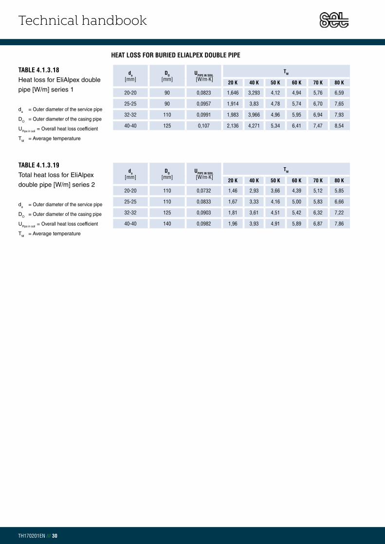
Technical handbook
TH170201EN /// 30
HEAT LOSS FOR BURIED ELIALPEX DOUBLE PIPE
TABLE 4.1.3.18Heat loss for EliAlpex double
pipe [W/m] series 1
da = Outer diameter of the service pipe
DO = Outer diameter of the casing pipe
UPipe in soil = Overall heat loss coefficient
TM = Average temperature
TABLE 4.1.3.19Total heat loss for EliAlpex
double pipe [W/m] series 2
da = Outer diameter of the service pipe
DO = Outer diameter of the casing pipe
UPipe in soil = Overall heat loss coefficient
TM = Average temperature
da[mm]
DO[mm]
UPIPE IN SOIL [W/m·K]
TM
20 K 40 K 50 K 60 K 70 K 80 K
20-20 90 0,0823 1,646 3,293 4,12 4,94 5,76 6,59
25-25 90 0,0957 1,914 3,83 4,78 5,74 6,70 7,65
32-32 110 0,0991 1,983 3,966 4,96 5,95 6,94 7,93
40-40 125 0,107 2,136 4,271 5,34 6,41 7,47 8,54
da[mm]
DO[mm]
UPIPE IN SOIL [W/m·K]
TM
20 K 40 K 50 K 60 K 70 K 80 K
20-20 110 0,0732 1,46 2,93 3,66 4,39 5,12 5,85
25-25 110 0,0833 1,67 3,33 4,16 5,00 5,83 6,66
32-32 125 0,0903 1,81 3,61 4,51 5,42 6,32 7,22
40-40 140 0,0982 1,96 3,93 4,91 5,89 6,87 7,86

Technical handbook
TH170201EN /// 31
CHAPTER 4.2TRANSPORT AND STORAGE
Flexible pipes are produced in coils and different lengths depending on dimension
and order request. Caution must be shown with loading and unloading the pipes to
avoid damaging the PE casing. When using a fork-lift, it is necessary to cover the
forks with protection. When using a crane it is recommended to use wide flat nylon
web sling for hoisting. The loading area of transportation trucks should be a smooth,
clean surfaces, void of any particles.
LOADINGDuring loading and unloading regulations must be followed to minimize the risk of
accidents. Ensure no one is nearby and the loading operator should be located at a
safe distance.
All equipment used for loading must be certificated, with a CE label and a specified
maximum weight capacity. Use only flat nylon web sling wider than 100 mm during
loading. Do not use chains, ropes, wires or other lifting equipment. Do not allow pipes
or fittings to drop down from the vehicle. Casing pipe is sensitive to sharp edges and
heavy force. Ensure casing pipe is undamaged to avoid further damage to pipes
once in use
Flexible Pipes should be stored lying down or standing on a flat surface, preferably
on soft soil or sand. If storing pipes on a hard surface ensure it is clear of all rocks,
stones and other foreign objects. Avoid water coming in contact with pipe ends or
pipe ends will need to be cut before laying.

Technical handbook
TH170201EN /// 32
FITTINGSFittings shall be stored so the insulation surface leans downward and is free from
any water.
ATTENTION. Caution should be shown when releasing the binding holding the coils
together due to risk of injury with tension release. It is safest to stand inside the coil
when releasing binding. Do not lay the pipes if the outside temperature is below
+5°C. If storing pipes for long periods of time it is necessary to protect them from
corrosion.
PUR INSULATION AND JOINT MATERIALStore PEH shrinkable casing, sleeves, expansion pads and other accessories
where they are protected from cold weather and direct sunlight. Liquid insulation
components in barrels, bottles or bags must be stored in a secured area at
a temperature between +10 and +20°C. Insulation material Poly (light coloured)
and Isocyanate (dark coloured) may under no circumstances freeze or reach
a temperature below 0°C during use or storage. Otherwise the foam can crystallize
and be no longer possible to use.
FIG 4.2.1 Bends and T-pieces.
Allow insulation surface
to lean downward
FIG 4.2.2 Fork-lift with protection pipes

Technical handbook
TH170201EN /// 33
CHAPTER 4.3 FIELD WORK
CHAPTER 4.3.2 TRENCH
CHAPTER 4.3.1WEATHER CONDITIONS
PIPE-LAYINGThe casing pipe and insulation foam move axially with the expansion of the service
pipe as happens with the pre-insulated rigid pipes. The expansion is not taken into
account during the pipe-laying due to the self-compensation of the flexible pipes
from Set Pipes. The service pipe can only transport a small pressure force and easily
overcomes outer forces. However, these requirements have to be considered before
laying of bigger pipes (da = 75 – 110) into houses, as the pipe bends slightly and
therefore no movement occurs inside the building.
If ploughing the pipes down it is necessary to ensure suitable soil. Do not plough
pipes where there is a risk of stones that can damage the casing. Only plough in silt
and sandy soil.
WEATHER CONDITIONSIf the temperature drops below freezing the casing pipe is sensitive to heavy
impact. Set Pipes recommends if the temperature goes below 5°C to store the pipes
in a heated room. The heating needs to reach through the whole coil.
Transport and handling the coils in low temperatures must be done with care to
avoid breakage in the pipe.
TRENCH Figures 4.3.2.1 - 4.3.2.3 shows assembling of pipe and dimensions of the pipe
trench. The distance between the pipe and surface (H) should be between 0,60 – 1,2
m. Under special installation circumstances, like for a shallower trench or when the
trench lays under a road, please contact Set Pipe´s technical department for further
information.
The following tables show the minimum trench width (B) and the minimum distance
between pipes needed (C) according to casing pipe diameter

Technical handbook
TH170201EN /// 34
Da 75 90 110 125 140 160 180
C 150 150 150 150 150 150 150
B 500 530 570 600 630 670 710
TABLE 4.3.2.1Minimum trench width with
vertical parallel pipes [mm]
FIG 4.3.2.1Trench cross section

Technical handbook
TH170201EN /// 35
Da 75 90 110 125 140 160 180
C 150 150 150 150 150 150 150
B 275 290 310 325 340 360 380
TABLE 4.3.2.2Minimum trench width with
horizontal parallel pipes [mm]
FIG 4.3.2.2Trench cross section

Technical handbook
TH170201EN /// 36
Da 90 110 125 140 160 180
C 290 310 325 340 360 380
TABLE 4.3.2.3Minimum trench width with
double pipes [mm]
FIG 4.3.2.3Trench cross section
If the pipe assembly must be done in the trench it is necessary to ensure enough
trench width to meet all requirements.

Technical handbook
TH170201EN /// 37
BACKFILLING 1Before backfilling of the trench the following points must be reviewed:
- Pipe-laying guidelines are followed
- Verification jointing is secure
- Stones and foreign objects which may have fallen from trench
bank during assembly are removed
To minimize heat loss from the ground surface use stone free fine sand that is free
from plant residues, humus, clay and silt lumps.
The sand must comply with following grain sizes to be classified as backfilling material 1:
Begin trench filling with compacted sand ensuring the layer is at least 0,10 m after
compacting. The pipes are laid in the trench with the correct distance between (B)
and the minimum distance from the outer casing and surface is 0,10 m.
It is necessary to compact the sand well around the pipes, allowing for the
predisposed friction between outer casing and backfill. Ensure the sand is
compacted simultaneously on both sides to avoid pipes moving out of place.
The backfill shall be made up in a way that neither its properties nor the compaction
causes damage to pipe and joints. See figures 4.3.2.1, 4.3.2.2 og 4.3.2.3.
The sand layer above the district heating pipe should be minimum 0,10 m after
compaction.
BACKFILLING 2Before using backfilling material 2 place a warning type at a distance of approx.
0,20 – 0,50 m above the pipeline. Make sure that the backfilling material 2 does not
damage the pipe or the fittings. In some cases the material from the trench can
be reused, but only if it contains a very small amount of organic material (e.g.
humus and clay). Remove bigger stones/rocks and other undesirable material. The
backfilling should follow in layers and compacted with necessary equipment which
reaches 20 N/cm2. The first backfilling layer must be fine-grained and the following
layer can be coarse, but each layer must always be at least 0,20 m after compaction.
MEDIUM GRAINED SAND 0-4 mm
FINE GRAINED SAND Max 8%
MAXIMUM GRAIN SIZE ≤ 32 mm
MAXIMUM GRAIN SIZE 10% OF WEIGHT ≤ 0,075 mm
MAXIMUM GRAIN SIZE 3% OF WEIGHT ≤ 0,020 mm
COEFFICIENT OF UNIFORMITY d60/d10 > 1,8
TABLE 4.3.3.1Backfilling material 1
description
CHAPTER 4.3.3 BACKFILLING

Technical handbook
TH170201EN /// 38
BENDING RADIUS – FLEXIBLE PIPESThe minimum bending radius for Eli-products is very low and is therefore ideal for
example in house connections. Avoid any sharp edges when bending. Material
flexibility depends on the temperature. In low temperatures (see „weather
conditions “) the pipe must be pre-heated to reach the minimum bending radius.
CASING PIPE [mm]
ELIPEX[m]
ELICOPP[m]
ELISTEEL[m]
ELIALPEX[m]
75 0,60 0,75 0,75 0,65
90 0,75 0,80 0,80 0,80
110 0,78 0,82 0,82 0,83
125 0,83 0,90 0,90 0,90
140 0,85 - - -
160 0,90 - - -
180 0,95 - - -
TABLE 4.3.4.1Minimum bending radius rmin
for flexible pipes
CHAPTER 4.3.4 BENDING RADIUS – FLEXIBLE PIPES

Technical handbook
TH170201EN /// 39
SDR 11Art no.
Pex pipe Casing pipe Do [mm]
Weight[kg/m]do [mm] di [mm] t [mm]
11.101.020 20 16,2 1,9 75 0,80
11.101.025 25 20,4 2,3 75 0,84
11.101.032 32 26,2 2,9 75 0,92
11.101.040 40 32,6 3,7 90 1,3
11.101.050 50 40,8 4,6 110 1,8
11.101.063 63 51,4 5,8 125 2,4
11.101.075 75 61,4 6,8 140 3,2
11.101.090 90 73,6 8,2 160 4,1
11.101.110 110 87,6 11,2 180 5,4
SDR 11Art no.
Pex pipe Casing pipe Do [mm]
Weight[kg/m]do [mm] di [mm] t [mm]
11.201.020 20 16,2 1,9 90 1,0
11.201.025 25 20,4 2,3 90 1,0
11.201.032 32 26,2 2,9 90 1,1
11.201.040 40 32,6 3,7 110 1,6
11.201.050 50 40,8 4,6 125 2,0
11.201.063 63 51,4 5,8 140 2,9
11.201.075 75 61,4 6,8 160 3,6
11.201.090 90 73,6 8,2 180 4,6
CHAPTER 4.9.1SINGLE PRE-INSULATED SDR 11 PEX-PIPESINSULATION SERIES 1
SINGLE PRE-INSULATED SDR 11 PEX-PIPESINSULATION SERIES 2
CHAPTER 4.9.2DOUBLE PRE-INSULATED SDR 11 PEX-PIPESINSULATION SERIES 1
SDR 11Art no.
Pex pipe Casing pipe Do [mm]
Weight[kg/m]do1 - do2 [mm] di [mm] t [mm]
11.106.020 20-20 16,2 1,9 90 1,0
11.106.025 25-25 20,4 2,3 90 1,0
11.106.032 32-32 26,2 2,9 110 1,5
11.106.040 40-40 32,6 3,7 125 1,9
11.106.050 50-50 40,8 4,6 160 3,0
11.106.063 63-63 51,4 5,8 180 3,8
SDR 11Art no.
Pex pipe Casing pipe Do [mm]
Weight[kg/m]do1 - do2 [mm] di [mm] t [mm]
11.206.020 20-20 16,2 1,9 90 1,3
11.206.025 25-25 20,4 2,3 110 1,5
11.206.032 32-32 26,2 2,9 125 1,8
11.206.040 40-40 32,6 3,7 140 2,4
11.206.050 50-50 40,8 4,6 180 3,5
DOUBLE PRE-INSULATED SDR 11 PEX-PIPESINSULATION SERIES 2
CHAPTER 4.9 PRODUCT CATALOGUE – FLEXIBLE DISTRICT HEATING PIPES

Technical handbook
TH170201EN /// 40
SDR 7,4Art no.
Pex pipe Casing pipe Do [mm]
Weight[kg/m]do [mm] di [mm] t [mm]
11.102.020 20 14,4 2,8 75 0,84
11.102.025 25 18,0 3,5 75 0,91
11.102.032 32 23,2 4,4 75 1,0
11.102.040 40 29,0 5,5 90 1,4
11.102.050 50 36,2 6,9 110 2,1
11.102.063 63 45,8 8,6 125 2,8
SDR 7,4Art no.
Pex pipe Casing pipe Do [mm]
Weight[kg/m]do [mm] di [mm] t [mm]
11.202.020 20 14,4 2,8 90 1,0
11.202.025 25 18,0 3,5 90 1,1
11.202.032 32 23,2 4,4 90 1,2
11.202.040 40 29,0 5,5 110 1,8
11.202.050 50 36,2 6,9 125 2,4
11.202.063 63 45,8 8,6 140 3,3
CHAPTER 4.9.3SINGLE PRE-INSULATED SDR 7,4 PEX-PIPEINSULATION SERIES 1
SINGLE PRE-INSULATED SDR 7,4 PEX-PIPEINSULATION SERIES 2
CHAPTER 4.9.4DOUBLE PRE-INSULATED SDR 7,4 PEX-PIPES INSULATION SERIES 1
SDR 7,4Art no.
Pex pipe Casing pipe Do [mm]
Weight[kg/m]do1 - do2 [mm] di [mm] t [mm]
11.107.025 25-20 18,0 3,5 90 2.0
11.107.032 32-20 23,2 4,4 110 2,0
11.107.040 40-25 29,0 5,5 125 2,5
11.107.050 50-32 36,2 6,9 140 3,5
11.107.063 63-40 45,8 8,6 160 4,6

Technical handbook
TH170201EN /// 41
CHAPTER 4.9.5SINGLE PEX BEND 90° INSULATION SERIES 1
SDR 11 Art no.
Pex pipedo [mm]
Casing pipe Do [mm]
LengthL1/L2 [mm]
Weight[kg/pc]
11.110.020 20 75 1000 2,8
11.110.025 25 75 1000 2,9
11.110.032 32 75 1000 3,3
11.110.040 40 90 1000 4,8
11.110.050 50 110 1000 7,0
11.110.063 63 125 1000 9,5
11.110.075 75 140 1000 12,9
11.110.090 90 160 1000 16,8
11.110.110 110 180 1000 16,8
SDR 11 Art no.
Pex pipedo1 - do2 [mm]
Casing pipe Do [mm]
LengthL1/L2 [mm]
Weight[kg/pc]
11.116.020 20-20 90 1000 5,0
11.116.025 25-25 90 1000 5,2
11.116.032 32-32 110 1000 5,9
11.116.040 40-40 125 1000 8,6
11.116.050 50-50 160 1000 12,6
11.116.063 63-63 180 1000 17,1
SDR 11 Art no.
Pex pipedo [mm]
Casing pipe Do [mm]
LengthL1/L2 [mm]
Weight[kg/pc]
11.210.020 20 90 1000 3,6
11.210.025 25 90 1000 3,7
11.210.032 32 90 1000 4,1
11.210.040 40 110 1000 6,2
11.210.050 50 125 1000 8,2
11.210.063 63 140 1000 10,9
11.210.075 75 160 1000 12,7
11.210.090 90 180 1000 13,9
DOUBLE PEX BEND 90° INSULATION SERIES 2
SDR 11 Art no.
Pex pipedo1 - do2 [mm]
Casing pipe Do [mm]
LengthL1/L2 [mm]
Weight[kg/pc]
11.216.020 20-20 90 1000 5,0
11.216.025 25-25 110 1000 5,2
11.216.032 32-32 125 1000 5,9
11.216.040 40-40 140 1000 8,6
11.216.050 50-50 180 1000 12,6
CHAPTER 4.9.6DOUBLE PEX BEND 90° INSULATION SERIES 1
SINGLE PEX BEND 90° INSULATION SERIES 2

Technical handbook
TH170201EN /// 42
CHAPTER 4.9.7SINGLE PEX BEND 90°INSULATION SERIES 1
SDR 7,4Art no.
Pex pipedo [mm]
Casing pipe Do [mm]
LengthL1/L2 [mm]
Weight[kg/pc]
11.112.020 20 75 1000 2,9
11.112.025 25 75 1000 3,1
11.112.032 32 75 1000 3,7
11.112.040 40 90 1000 5,3
11.112.050 50 110 1000 7,8
11.112.063 63 125 1000 10,7
SDR 7,4Art no.
Pex pipedo1 - do2 [mm]
Casing pipe Do [mm]
LengthL1/L2 [mm]
Weight[kg/pc]
11.117.025 25-20 90 1000 5,6
11.117.032 32-20 110 1000 6,7
11.117.040 40-25 125 1000 9,5
11.117.050 50-32 140 1000 14,0
11.117.063 63-40 160 1000 19,3
SDR 7,4Art no.
Pex pipedo [mm]
Casing pipe Do [mm]
LengthL1/L2 [mm]
Weight[kg/pc]
11.212.020 20 90 1000 3,7
11.212.025 25 90 1000 3,9
11.212.032 32 90 1000 4,4
11.212.040 40 110 1000 6,8
11.212.050 50 125 1000 9,0
11.212.063 63 140 1000 12,2
CHAPTER 4.9.8DOUBLE PEX BEND 90° INSULATION SERIES 1
SINGLE PEX BEND 90°INSULATION SERIES 2

Technical handbook
TH170201EN /// 43
CHAPTER 4.9.9SINGLE PEX BRANCH STRAIGHTINSULATION SERIES 1
SINGLE PEX BRANCH STRAIGHTINSULATION SERIES 1
SDR 11Art.no
Main pipe BranchLength[mm]
Weight[kg/spc]PEX
do [mm]Casing pipe
D1 [mm]PEX
do [mm]Casing pipe
D1 [mm]
11.120.020.020 20 75 20 75 1000/1000 2,0
11.120.025.025 25 75 25 75 1000/1000 2,2
11.120.032.032 32 75 32 75 1000/1000 2,4
11.120.032.025 32 75 25 75 1000/1000 2,3
11.120.040.020 40 90 20 75 1000/1000 2,5
11.120.040.025 40 90 25 75 1000/1000 2,9
11.120.040.032 40 90 32 75 1000/1000 3,1
11.120.040.040 40 90 40 90 1000/1000 3,5
11.120.050.025 50 110 25 75 1000/1000 3,8
11.120.050.032 50 110 32 75 1000/1000 3,9
11.120.050.040 50 110 40 90 1000/1000 4,4
11.120.050.050 50 110 50 110 1000/1000 5,0
11.120.063.025 63 125 25 75 1000/1000 4,9
11.120.063.032 63 125 32 75 1000/1000 5,0
11.120.063.040 63 125 40 90 1000/1000 5,9
11.120.063.050 63 125 50 110 1000/1000 6,7
11.120.063.063 63 125 63 125 1000/1000 6,7
11.120.075.025 75 140 25 75 1000/1000 6,6
11.120.075.032 75 140 32 75 1000/1000 6,7
11.120.075.040 75 140 40 90 1000/1000 7,3
11.120.075.050 75 140 50 110 1000/1000 8,1
11.120.075.063 75 140 63 125 1000/1000 9,3
11.120.075.075 75 140 75 140 1000/1000 10,5
11.120.090.025 90 160 25 75 1000/1000 8,6
11.120.090.032 90 160 32 75 1000/1000 8,6
11.120.090.040 90 160 40 90 1000/1000 9,0
11.120.090.050 90 160 50 110 1000/1000 10,2
11.120.090.063 90 160 63 125 1000/1000 11,2
11.120.090.075 90 160 75 140 1000/1000 12,1
11.120.090.090 90 160 90 160 1000/1000 12,1
SDR 7,4Art.no
Main pipe BranchLength[mm]
Weight[kg/spc]PEX
do [mm]Casing pipe
D1 [mm]PEX
do [mm]Casing pipe
D1 [mm]
11.122.020.020 20 75 20 75 1000/1000 2,0
11.122.025.025 25 75 25 75 1000/1000 2,3
11.122.032.025 32 75 25 75 1000/1000 2,5
11.122.032.032 32 75 32 75 1000/1000 2,7
11.122.040.025 40 90 25 75 1000/1000 3,2
11.122.040.032 40 90 32 75 1000/1000 3,4
11.122.040.040 40 90 40 90 1000/1000 4,0
11.122.050.025 50 110 25 75 1000/1000 4,2
11.122.050.032 50 110 32 75 1000/1000 4,3
11.122.050.040 50 110 40 90 1000/1000 4,8
11.122.050.050 50 110 50 110 1000/1000 5,9
11.122.063.025 63 125 25 75 1000/1000 5,5
11.122.063.032 63 125 32 75 1000/1000 5,8
11.122.063.040 63 125 40 90 1000/1000 6,4
11.122.063.050 63 125 50 110 1000/1000 7,4
11.122.063.063 63 125 63 125 1000/1000 8,6

Technical handbook
TH170201EN /// 44
SINGLE PEX BRANCH STRAIGHTINSULATION SERIES 2
SINGLE PEX BRANCH STRAIGHTINSULATION SERIES 2
SDR 11Art.no
Main pipe BranchLength[mm]
Weight[kg/spc]PEX
do [mm]Casing pipe
D1 [mm]PEX
do [mm]Casing pipe
D1 [mm]
11.220.025.025 25 90 25 90 1000/1000 2,8
11.220.032.025 32 90 25 90 1000/1000 2,8
11.220.032.032 32 90 32 90 1000/1000 3,0
11.220.040.025 40 110 25 90 1000/1000 3,7
11.220.040.032 40 110 32 90 1000/1000 3,8
11.220.040.040 40 110 40 110 1000/1000 4,5
11.220.050.025 50 125 25 90 1000/1000 4,5
11.220.050.032 50 125 32 90 1000/1000 4,6
11.220.050.040 50 125 40 110 1000/1000 5,3
11.220.050.050 50 125 50 125 1000/1000 5,8
11.220.063.025 63 140 25 90 1000/1000 5,7
11.220.063.032 63 140 32 90 1000/1000 5,7
11.220.063.040 63 140 40 110 1000/1000 6,8
11.220.063.050 63 140 50 125 1000/1000 7,6
11.220.063.063 63 140 63 140 1000/1000 7,8
11.220.075.025 75 160 25 90 1000/1000 7,4
11.220.075.032 75 160 32 90 1000/1000 7,5
11.220.075.040 75 160 40 110 1000/1000 8,4
11.220.075.050 75 160 50 125 1000/1000 9,1
11.220.075.063 75 160 63 140 1000/1000 10,4
11.220.075.075 75 160 75 160 1000/1000 11,7
11.220.090.025 90 180 25 90 1000/1000 8,8
11.220.090.032 90 180 32 90 1000/1000 8,9
11.220.090.040 90 180 40 110 1000/1000 9,5
11.220.090.050 90 180 50 125 1000/1000 10,6
11.220.090.063 90 180 63 140 1000/1000 11,7
11.220.090.075 90 180 75 160 1000/1000 12,6
11.220.090.090 90 180 90 180 1000/1000 12,7
SDR 7,4Art.no
Main pipe BranchLength[mm]
Weight[kg/spc]PEX
do [mm]Casing pipe
D1 [mm]PEX
do [mm]Casing pipe
D1 [mm]
11.222.025.025 25 90 25 90 1000/1000 2,8
11.222.032.025 32 90 25 90 1000/1000 3,0
11.222.032.032 32 90 32 90 1000/1000 3,2
11.222.040.025 40 110 25 90 1000/1000 4,0
11.222.040.032 40 110 32 90 1000/1000 4,1
11.222.040.040 40 110 40 110 1000/1000 4,9
11.222.050.025 50 125 25 90 1000/1000 4,8
11.222.050.032 50 125 32 90 1000/1000 5,0
11.222.050.040 50 125 40 110 1000/1000 5,7
11.222.050.050 50 125 50 125 1000/1000 6,7
11.222.063.025 63 140 25 90 1000/1000 6,2
11.222.063.032 63 140 32 90 1000/1000 6,5
11.222.063.040 63 140 40 110 1000/1000 7,4
11.222.063.050 63 140 50 125 1000/1000 8,3
11.222.063.063 63 140 63 140 1000/1000 9,6

Technical handbook
TH170201EN /// 45
CHAPTER 4.9.10PRE-INSULATED COPPER PIPESINSULATION SERIES 1
PRE-INSULATED COPPER PIPESINSULATION SERIES 2
CHAPTER 4.9.11DOUBLE PRE-INSULATED COPPER PIPESINSULATION SERIES 1
DOUBLE PRE-INSULATED COPPER PIPESINSULATION SERIES 2
Art no. Copper pipe Casing pipe
Do [mm]Weight[kg/m]do [mm] di [mm] t mm]
11.108.015 15 13,0 1,0 75 1,1
11.108.018 18 16,0 1,0 75 1,2
11.108.022 22 20,0 1,0 75 1,3
11.108.028 28 25,6 1,2 75 1,6
Art no. Copper pipe Casing pipe
Do [mm]Weight[kg/m]do [mm] di [mm] t mm]
11.208.015 15 13,0 1,0 90 1,3
11.208.018 18 16,0 1,0 90 1,4
11.208.022 22 20,0 1,0 90 1,5
11.208.028 28 25,6 1,2 90 1,8
Art no. Copper pipe Casing pipe
Do [mm]Weight[kg/m]do1 - do2 [mm] di [mm] t mm]
11.109.015 15-15 13,0 1,0 90 1,7
11.109.018 18-18 16,0 1,0 90 1,8
11.109.022 22-22 20,0 1,0 90 2,1
11.109.028 28-28 25,6 1,2 110 3,1
Art no. Copper pipe Casing pipe
Do [mm]Weight[kg/m]do1 - do2 [mm] di [mm] t mm]
11.209.015 15-15 13,0 1,0 110 2,1
11.209.018 18-18 16,0 1,0 110 2,2
11.209.022 22-22 20,0 1,0 110 2,5
11.209.028 28-28 25,6 1,2 125 3,3

Technical handbook
TH170201EN /// 46
CHAPTER 4.9.12SINGLE PRE-INSULATED FLEXIBLE STEEL PIPESINSULATION SERIES 1
SINGLE PRE-INSULATED FLEXIBLE STEEL PIPESINSULATION SERIES 2
CHAPTER 4.9.13DOUBLE PRE-INSULATEDFLEXIBLE STEEL PIPESINSULATION SERIES 1
DOUBLE PRE-INSULATEDFLEXIBLE STEEL PIPESINSULATION SERIES 2
ELISTEELArt no.
Steel pipe Casing pipe Do [mm]
Weight[kg/m]do [mm] di [mm] t [mm]
11.1001.020 20 16,0 2,0 75 1,6
11.1001.025 25 21,0 2,0 75 1,8
11.1001.028 28 24,0 2,0 75 2,0
ELISTEELArt no.
Steel pipe Casing pipe Do [mm]
Weight[kg/m]do [mm] di [mm] t [mm]
11.2001.020 20 16,0 2,0 90 1,8
11.2001.025 25 21,0 2,0 90 2,0
11.2001.028 28 24,0 2,0 90 2,2
ELISTEELArt no.
Steel pipe Casing pipe Do [mm]
Weight[kg/m]do1 - do2 [mm] di [mm] t [mm]
11.1002.020 20-20 16,0 2,0 90 2,7
11.1002.025 25-25 21,0 2,0 90 3,1
11.1002.028 28-28 24,0 2,0 110 3,8
ELISTEELArt no.
Steel pipe Casing pipe Do [mm]
Weight[kg/m]do1 - do2 [mm] di [mm] t [mm]
11.2002.020 20-20 16,0 2,0 110 3,1
11.2002.025 25-25 21,0 2,0 110 3,5
11.2002.028 28-28 24,0 2,0 125 4,1

Technical handbook
TH170201EN /// 47
CHAPTER 4.9.14SINGLE PRE-INSULATED ALUMINUM/PEX- PIPESINSULATION SERIES 1
ELIALIPEXArt no.
Aluminum/Pex pipe Casing pipe Do [mm]
Weight[kg/m]do [mm] di [mm] t [mm]
11.103.020 20 14,2 2,9 75 0,84
11.103.025 25 17,6 3,7 75 0,92
11.103.032 32 22,6 4,7 75 1,0
11.103.040 40 29,2 5,4 90 1,4
ELIALIPEXArt no.
Aluminum/Pex pipe Casing pipe Do [mm]
Weight[kg/m]do [mm] di [mm] t [mm]
11.203.020 20 14,2 2,9 90 1,1
11.203.025 25 17,6 3,7 90 1,1
11.203.032 32 22,6 4,7 90 1,3
11.203.040 40 29,2 5,4 110 1,8
ELIALIPEXArt no.
Aluminum/Pex pipe Casing pipe Do [mm]
Weight[kg/m]do1 - do2 [mm] di [mm] t [mm]
11.103.020.020 20-20 14,2 2,9 90 1,1
11.103.025.025 25-25 17,6 3,7 90 1,1
11.103.032.032 32-32 22,6 4,7 110 1,7
11.103.040.040 40-40 29,2 5,4 125 2,1
ELIALIPEXArt no.
Aluminum/Pex pipe Casing pipe Do [mm]
Weight[kg/m]do1 - do2 [mm] di [mm] t [mm]
11.203.020.020 20-20 14,2 2,9 110 1,5
11.203.025.025 25-25 17,6 3,7 110 1,4
11.203.032.032 32-32 22,6 4,7 125 1,9
11.203.040.040 40-40 29,2 5,4 140 2,6
DOUBLE PRE-INSULATED ALUMINUM/PEX- PIPESINSULATION SERIES 2
CHAPTER 4.9.15DOUBLE PRE-INSULATED ALUMINUM/PEX- PIPESINSULATION SERIES 1
SINGLE PRE-INSULATED ALUMINUM/PEX- PIPESINSULATION SERIES 2

Technical handbook
TH170201EN
Chapter 5 | Joint material
5.0 – Joint material – System design ............................................................ 1
5.0.1 – PE shrink casing ............................................................................... 1
5.0.2 – PE electric welding casing ............................................................ 2
5.0.3 – PE end closure ................................................................................... 3
5.0.4 – PE shrink reduction casing ............................................................ 4
5.1 – Shrink material .......................................................................................... 4
5.1.1 – Application range ................................................................................ 4
5.2 – PUR foam ..................................................................................................... 6
5.3 – PUR insulation shell ................................................................................. 7
5.4 – Instructions for shrink casings ............................................................. 8
5.5 – Machinery and accessories for electric welding casing ............. 9
5.6 – Pex joint material ................................................................................... 10
5.7 – Accessories ............................................................................................... 11
5.8 – Storage ...................................................................................................... 12
5.9 – Product catalogue ................................................................................ 13
TABLE OF CONTENT

Technical handbook
TH170201EN /// 1
CHAPTER 5.0.1PE SHRINK CASING – SPECIFICATION
CHAPTER 5.0JOINT MATERIAL
APPLICATION RANGEThese specifications are made for PE shrink casings for pre-insulated single and
double district heating systems. A conventional heat-shrink casing with a sealing
strip between the casing pipe and shrink casing to ensure strong connections.
(Chapter 5.0.1.1) and are delivered in a white protection plastic.
MATERIALPE shrink casings are produced in accordance with the European standard EN 489.
The PE shrink casings are resilient, with a high chemical resistance and are
therefore an optimal protection over PUR foam. The PE shrink casings are
produced containing carbon black for sunlight protection, seamless, and are coated
with corona treated polyethylene for maximum adhesion to the PUR foam.
The main characteristics of the PE shrink casings are as follows:
MATERIAL Polyethelyne - PE100
COLOUR Carbon black > 2,5 % of the mass according to EN 253 chapter 4.3.1.1
MATERIAL PROPERTIES EN 253 Chapter 4.3.1.1
MINIMUM WALL THICKNESS EN 253 Chapter 4.3.2.2 Table 6
THERMAL CONDUCTIVITY 0,40 W/m·K
MELT FLOW INDEX 0,20 - 1,4 g/10 min. according to EN 253 Chapter 4.3.1.2
TABLE 5.0.1.1PE shrink casings properties
DO
t[mm]
L[mm]
DO[mm]
t2[mm]
L[mm]
90 3,0 600 400 5,6 600
110 3,0 600 450 6,3 600
125 3,0 600 500 7,0 700
140 3,0 600 560 7,8 700
160 3,0 600 630 8,8 700
180 3,0 600 710 9,8 700
200 3,2 600 800 11,1 700
225 3,5 600 900 12,5 700
250 3,9 600
280 4,4 600
315 4,5 600
355 4,5 600
TABLE 5.0.1.2PE shrink casings
Do = Outer diameter of casing pipe
t = Casing pipe wall thickness
Di = Inner diameter of the shrink casing
L = Length of the shrink casing
Set Pipes requires that each of its suppliers meet the highest standards for all
material. All suppliers have to be certified according to ISO 9001 and they are
evaluated before further cooperation. The quality of incoming materials is tested and
documented in accordance with EN 489 and EN 253.
Set pipes can provide conventional closed PE shrinkable casings with shrink
sleeves, closed PE electric welding casings and open sleeves which can be used
onsite after the pipes have been connected.

Technical handbook
TH170201EN /// 2
CHAPTER 5.0.2PE ELECTRIC WELDING CASING – SPECIFICATION
APPLICATION RANGEThese specifications are made for PE electric welding casing for pre-insulated
single and double district heating systems. Electrofusion ensures complete PE
jointing in difficult conditions. The electric welding casing is usually used for larger pipe
dimensions.
MATERIALPE electric welding casings are produced in accordance with the European standard
EN 489.
The PE electric welding casings are resilient, with a high chemical resistance and
are therefore an optimal protection over PUR foam. The PE shrink casings are
produced containing carbon black for sunlight protection, seamless, and are coated
with corona treated polyethylene for maximum adhesion to the PUR foam.
The main characteristics of the PE electric welding casings are as follows:
TABLE 5.0.2.1PE electric welding
casing properties
MATERIAL Polyethelyne - PE100
COLOUR Carbon black > 2,5 % of the mass according to EN 253 chapter 4.3.1.1
MATERIAL PROPERTIES EN 253 Chapter 4.3.1.1
MINIMUM WALL THICKNESS EN 253 Chapter 4.3.2.2 Table 6
THERMAL CONDUCTIVITY 0,40 W/m·K
MELT FLOW INDEX 0,20 - 1,4 g/10 min. according to EN 253 Chapter 4.3.1.2
STANDARD LENGTH 700 mm.
DO[mm]
t[mm]
L[mm]
DO[mm]
t[mm]
L[mm]
90 4,0 600 400 5,6 700
110 4,0 600 450 6,3 700
125 4,1 600 500 7,0 700
140 4,5 600 560 7,8 700
160 5,0 600 630 8,8 700
180 5,0 600 710 9,8 800
200 5,0 600 800 11,1 800
225 5,5 600 900 12,5 800
250 6,1 600
280 4,4 600
315 4,5 600
355 4,5 700
TABLE 5.0.2.2PE electric welding casing
Do = Outer diameter of casing pipe
t = Casing pipe wall thickness
Di = Inner diameter of electric
welding casing
L = Length of electric welding
casing

Technical handbook
TH170201EN /// 3
CHAPTER 5.0.3PE END CLOSURE – SPECIFICATION
APPLICATION RANGEThese specifications are made for PE end closures for pre-insulated single and
double district heating systems. PE end closures are suitable for insulated pipe ends
that may later be connected to additional pipelines.
SPECIFICATION PE end closures are produced in accordance with the European standard EN 489.
The PE end closures are resilient, with a high chemical resistance and are therefore
an optimal protection over PUR foam. The PE end closures are produced containing
carbon black for sunlight protection, seamless, and are coated with corona treated
polyethylene for maximum adhesion to the PUR foam.
The main characteristics of the PE end closures are as follows:
TABLE 5.0.3.1PE end closure properties
MATERIAL Polyethelyne - PE100
COLOUR Carbon black > 2,5 % of the mass according to EN 253 chapter 4.3.1.1
MATERIAL PROPERTIES EN 253 Chapter 4.3.1.1
MINIMUM WALL THICKNESS EN 253 Chapter 4.3.2.2 Table 6
THERMAL CONDUCTIVITY 0,40 W/m·K
MELT FLOW INDEX 0,20 - 1,4 g/10 min. according to EN 253 Chapter 4.3.1.2
STANDARD LENGTH 700 mm.
TABLE 5.0.3.2PE end closure properties
Do = Outer diameter of casing pipe
t = Casing pipe wall thickness
Di = Inner diameter of electric
welding casing
L = Length of electric welding
DO
t[mm]
L[mm]
DO[mm]
t2[mm]
L[mm]
90 3,0 600 400 5,6 600
110 3,0 600 450 6,3 600
125 3,0 600 500 7,0 700
140 3,0 600 560 7,8 700
160 3,0 600 630 8,8 700
180 3,0 600 710 9,8 700
200 3,2 600 800 11,1 700
225 3,5 600 900 12,5 700
250 3,9 600
280 4,4 600
315 4,5 600
355 4,5 600

Technical handbook
TH170201EN /// 4
CHAPTER 5.0.4PE SHRINK REDUCTION CASING – SPECIFICATION
APPLICATION RANGEThese specifications are made for PE shrink reduction casing for pre-insulated
single and double district heating systems. Shrink reduction casing are for variable
dimensions in pre-insulated pipe lines and are used together with steel reducers
to reduce between dimensions. A conventional PE shrink reduction casing with
a sealing strip in the end and are delivered in white protection plastic.
SPECIFICATIONPE shrink reduction casings are produced in accordance with the European standard
EN 489.
The PE shrink reduction casing are resilient, with a high chemical resistance
and are therefore an optimal protection over PUR foam. The PE shrink reduction
casing are produced containing carbon black for sunlight protection, seamless, and
are coated with corona treated polyethylene for maximum adhesion to the PUR foam.
The main characteristics of the PE shrink reduction casings are as follows:
MATERIAL Polyethelyne - PE100
COLOUR Carbon black > 2,5 % of the mass according to EN 253 chapter 4.3.1.1
MATERIAL PROPERTIES EN 253 Chapter 4.3.1.1
MINIMUM WALL THICKNESS EN 253 Chapter 4.3.2.2 Table 6
THERMAL CONDUCTIVITY 0,40 W/m·K
MELT FLOW INDEX 0,20 - 1,4 g/10 min. according to EN 253 Chapter 4.3.1.2
TABLE 5.0.4.1PE shrink reduction
casing properties
CHAPTER 5.1SHRINK MATERIAL
CHAPTER 5.1.1APPLICATION RANGE
Further details and sizes offered for PE shrink reductions can be found on page 20.
Shrink material is made from extruded cross-linked polyethylene (PEX) which
has been stretched in the production to get optimal contraction characteristics at
a certain heat temperature. These materials are used together with the shrink
casing joints to ensure a double seal. To ensure adhesion a sealing strip or glue which
becomes liquid when heated, is on the interior of shrink material. The heat resistance
of the shrink material is maximum 130°C and only a soft flame, should be used and
shortly, when shrinking. Shrink material from Set Pipes meets European standards
EN 489 and can be delivered in diverse variations as seen below.
SHRINK SLEEVES Available for district heating pipe with casing diameters 75 - 500 mm. Each shrink
sleeve is inseparable and both sleeves must be placed on the shrink casing before
the pipes are welded.

Technical handbook
TH170201EN /// 5
TABLE 5.1.1.1Shrink end caps for
single pipes
TABLE 5.1.1.2Shrink end caps for
double pipes
REPAIR STRIPSMainly for larger pipes and repairing of casing pipes. The strips can be placed
on joints after the welding process. Repair strips are delivered in rolls, widths of
150 – 900 mm.
LOCK STRIPSUsed over joints on repair strips to seal. Repair strips overlap and the lock strips are
then heated over the joint.
OPEN SHRINK SLEEVESUsed during assembly of joints, for example over PUR insulation shells. This is a thin
material and possible to cut to fit size of joint being worked with. The material shrinks
when heated.
SHRINK END CAPUsed to protect foam on ends of insulated pipes for example at house connections.
Single shrink end caps are available for DN 20 – 150. Double shrink end caps are
available for DN 20 - 90.
SHRINK HOSE FOR STEEL PIPESUsed to protect uninsulated steel pipes from corrosion for example at house connec-
tions. Shrink hoses are supplied in different widths and lengths.
Description Casing pipe dimension Flow pipes dimension
DHEC-2000 63-96 12-22
DHEC-2100 75-93 27-34
DHEC-2200 110-125 27-48
DHEC-2300 110-140 27-54
DHEC-2400 125-140 60-76
DHEC-2500 160-180 60-89
DHEC-2600 160-225 76-133
DHEC-2630 200-225 108-139
DHEC-2700 225-280 133-168
DHEC-2800 280-334 168-245
DHEC-2900 355-400 219-273
DHEC-3000 400-500 324-355
Description Casing pipe dimension Flow pipe dimension 1 Flow pipe dimension 2
DHEC-3200 90-125 10-28 10-28
DHEC-3250 90-140 19-34 10-21
DHEC-3280 110-160 24-60 20-50
DHEC-3300 140-180 24-48 14-28
DHEC-3350 160-180 24-62 24-62
DHEC-3351 160-180 24-32 24-32
DHEC-3352 160-200 24-49 24-49
DHEC-3360 160-200 24-34 50-62

Technical handbook
TH170201EN /// 6
The insulation foam (PUR or PU) consists of two components used as an
insulation on pipeline joints. Mixing these two components Polyol (component A) and
Isocyanate (component B) together results in a chemical reaction, where the
material heats up and expands, forming a polyurethane or urethane foam and gas
CO2.
The PUR foam is delivered in two bottles. The size according to required quantity
in regards to the joint and pipe dimensions used.
In addition, welding plugs, vent plugs and PE patches are needed for complete joint
closure.
Set Pipes can also deliver insulation foam in bags if necessary.
PRECAUTION: The polyurethane components, isocyanate and polyol, must be stored
and handled with caution. Store in a secure area away from unauthorized access,
at room temperature (18-20°C). Set Pipes will supply necessary safety data sheets.
CHAPTER 5.2PUR FOAM
GENERAL PROTECTIVE AND HYGIENIC MEASURESAvoid inhalation of vapours and spray. Wear both chemical resistant protective
clothing and gloves when handling isocyanate. Wear only suitable work clothes
and protective clothing. Do not eat, drink or smoke while in protective clothing.
Remove immediately all contaminated clothing. Hands and face should be washed
before breaks and after using.

Technical handbook
TH170201EN /// 7
USAGEEnsure everything is prepared for joint installation and drilling of pouring holes before
mixing foam.The content from the small bottle (polyol) is poured into the larger bottle
(isocyanate) and shaken vigorously for a short time (approx. 10-20 sec.). Pour the
mixture through the opening on the shrink casing and put the vent plug halfway into
the holes. Make sure the plugs point out to the side in regards to the pipeline.
PRECAUTION: Do not leave an empty or partially empty bottle with the cap tightly on
after mixing. Due to gas formation there is a risk of explosion and personal injury.
Do not seal the vent plug fully into the hole, if air/gas cannot release there is
a possibility of the casing joint being damaged or possibly exploding under the
pressure.
The foam should be used under well-ventilated conditions due to CO2 formation.
Set Pipes provides safety data sheets and they should always be placed where PU
components are stored and used.
CONDITIONSIn rain, a tent must be placed over the joint area. Avoid water entering the casing
joint. Foaming is not permitted at temperatures below 5°C, unless the casing joint is
preheated up to 60°C.
CHAPTER 5.3PUR INSULATION SHELL
Insulation shells can be used instead of an insulation foam, both for pipes with a
normal foam (PUR) as well as for high heat resistance foam (PIR). Insulation shells
are also available with a soft inner layer for PEX-, PE- and PP plastic carrier pipes.
The assembling of the insulation shells must be done with care to ensure they fit
exactly in the joint area. No space between the shells and the insulation end of the
pipe is allowed.
Technical handbook
TH170201EN /// 8
CHAPTER 5.4INSTRUCTIONS FOR JOINTS
To ensure all requirements regarding the system design and production of the district
heating pipes are fulfilled it is important that all work during the assembly process of
a pipeline is done precisely.
Studies show that careless work is one of the largest causes of pipeline failures.
The system lifetime and operational security is dependent on the work quality carried
out at the installation site.
Set Pipes requires that only trained and certified personnel work on the assembly of
district heating pipelines. Upon request, Set Pipes can offer training courses.
Instructions for the joint process can be found in chapter 7.
ATTENTION: After the joint assembly is finished it is necessary to foam the casing joint
on the same day to protect it against moisture. If water comes in contact with the
insulation foam it can affect the foam quality.

Technical handbook
TH170201EN /// 9
Mittel TSC® welding unit monitors the situation to ensure correct heating and
welding. Temperature, time and power are controlled automatically to achieve
a perfect result, regardless of fault sources and varying external temperature or
moisture. If the welding process deviates from the pre-set parameters, welding is
interrupted and a fault alarm goes on. In addition, the processor-controlled welding
unit automatically recognizes the pipe diameter and adjusts welding parameter –
this minimizes the system´s exposure to human errors. For better record keeping
Mittel TSC® welding unit is equipped with GPS, an in-built hard drive and Bluetooth
communication module. Thanks to these features you will always be able to trace
back every detail of a performed joint, its precise positioning, details of the welding
process, date, name of the technician who performed the work, etc.
There are two types of the TSC® welding machine as seen in more details in the
table below.
WELDING MACHINE TSC® PRO WELDING MACHINE TSC® MINI
TSC® PRO is equipped with two welding modules to shorten welding times and provide better productivity on large diameter pipes.
CHASING PIPE DIAMETER: 90 – 2000 mmPOWER CONSUMPTION: 230 V 2 x 3,1 kW 2 x 13 ADIMENSIONS (H X L X W): 380 x 360 x 240 mmWEIGHT: 14 kgPROTECTION: IP65TEMPERATURE MONITORING: DigitalLOGGING FUNCTION: YesGPS: YesCOMMUNICATION: Bluetooth®
TSC® MINI is a small and light welding machine that can handle all jobs up to 1000 mm.
CASING PIPE DIAMETER: 90 – 1000 mmPOWER CONSUMPTION: 230 V 3,1 kW 13 ADIMENSIONS (H X L X W): 260 x 360 x 240 mmWEIGHT: 9 kgPROTECTION: IP65TEMPERATURE MONITORING: DigitalLOGGING FUNCTION: YesGPS: YesCOMMUNICATION: Bluetooth®
WELDING TOOLSMittel´s welding tool are lightweight and easy to work with. In order to switch between
different pipe dimensions, you only need to change the Kevlar belt. The tool has an
in-built temperature sensor that indicates when the welded PE cools down to a safe
level.
SIZE RANGE: 90 - 2000 mm
WEIGHT: 2,8 kg
GENERATORA powerful generator is required to maintain steady voltage and frequency during the
welding process to prevent a damage to a sensitive electrical equipment.
CHAPTER 5.5WELDING MACHINE AND ACCESSORIES FOR ELECTRIC WELDING SLEEVE
TABLE 5.5.1Two types of TSC®
welding machines

Technical handbook
TH170201EN /// 10
CHAPTER 5.6PEX JOINTING SYSTEM
PRESS FITTINGSPress fittings for PEX-a district heating pipes are quick, safe, leak proof and
a permanent connection for PEX-a pipes, consisting of a simple fitting and
a compression sleeve. Additional sealing elements are not required, as the pipe itself
acts as a seal. Four sealing ribs guarantee a completely secure connection, which
also withstands the tough application conditions on construction sites. Specially
designed ribs on the compression sleeves prevent the connection coming
loose during operation. The fittings are made from brass, red brass or steel. The
compression sleeves are made from brass or red brass in dimensions from 20 – 125
mm.
For the press fittings connection to a PEX pipe special tools for the process are
needed. These tools are available from Set Pipes.
PLUG-IN FITTINGSPlug-in fittings are available in dimensions from 20 – 110 mm for PE, PEX-a and
PEX-c pipes. The fittings can withstand operating temperatures up to 95°C and the
maximum permissible operating pressure 10 bar. The assembly does not need any
special tools, simply screwed together and tightened with conventional tools. Screw
fittings are not a permanent seal but a detachable jointing technology. Note when
starting the heating system for the first time it is necessary to allow the fittings to
reach a temperature of 60 - 80 °C before finally tightening all connections. Screw
fittings come in a large variety including connectors, bends and reducers.
FUSAPEX ELECTROFUSION FITTINGSFusapex electrofusion fittings are made of cross-linked polyethylene (PEX-a) and
are resistant for operating temperatures up to 95°C and a maximum permissible
pressure of 6 bar. The connection between Fusapex and the district heating pipe has
to be assembled with a monomatic welding unit. The unit is available from Set Pipes.
This process is a simple, fast and secure connection with corrosion resistance. The
Fusapex electrofusion fittings are available in dimensions from 50 – 125 mm.
Chapter 5.9 shows some but not all of the PEX material. For support or special
requests please contact the sales or technical department at Set Pipes.
ASSEMBLY TEEAssembly tees are for PEX-a, PE and PP plastic pipes.
Insulated foam shells with sponge are placed around the tee and the PE tee casing
pipe aound the shells. Shrink sheets, shrink sleeves and lock strips, all cut to fit are
then used to complete the seal of the tee.
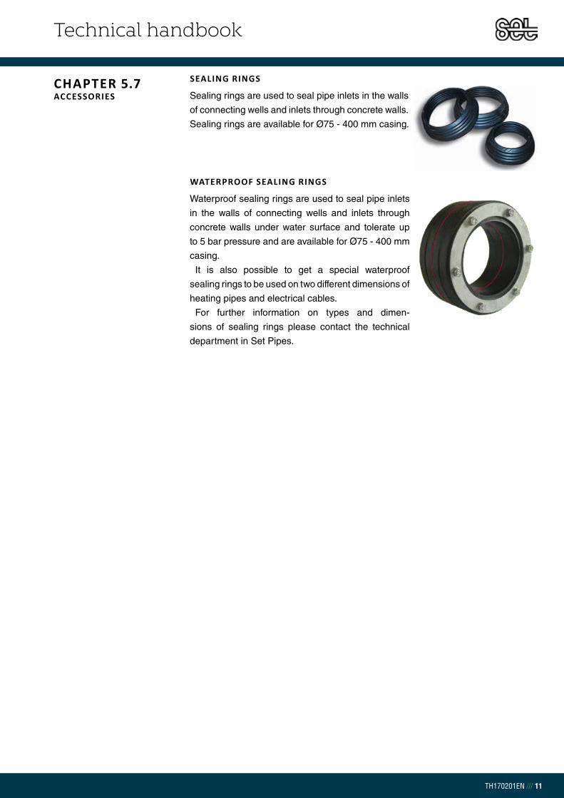
Technical handbook
TH170201EN /// 11
CHAPTER 5.7ACCESSORIES
SEALING RINGS
Sealing rings are used to seal pipe inlets in the walls
of connecting wells and inlets through concrete walls.
Sealing rings are available for Ø75 - 400 mm casing.
WATERPROOF SEALING RINGS
Waterproof sealing rings are used to seal pipe inlets
in the walls of connecting wells and inlets through
concrete walls under water surface and tolerate up
to 5 bar pressure and are available for Ø75 - 400 mm
casing.
It is also possible to get a special waterproof
sealing rings to be used on two different dimensions of
heating pipes and electrical cables.
For further information on types and dimen-
sions of sealing rings please contact the technical
department in Set Pipes.

Technical handbook
TH170201EN /// 12
CHAPTER 5.8 STORAGE
Shrink casing and shrink sleeve material shall be stored indoors at a constant
room temperature and dry air (5-20°C). High heat and direct sunlight may cause
premature shrinkage of the material. Store in an upright position avoiding any
external pressure.
Foam components shall be stored in a dry and well-ventilated area in temperatures
between 10 – 20°C, Avoid low temperatures and direct sunlight. Ensure the storage
area is secure to prevent access by children or unauthorized persons.

Technical handbook
TH170201EN /// 13
SDR 11Art no.
do[mm]
t[mm]
Length[mm]
Width[mm]
Weight[kg/pc]
10.80020 20 1,9 20 25 0,022
10.80025 25 2,3 27 30 0,040
10.80032 32 2,9 35 40 0,080
10.80040 40 3,7 37 49 0,13
10.80050 50 4,6 44 61 0,26
10.80063 63 5,8 53 74 0,39
10.80075 75 6,8 53 90 0,50
10.80090 90 8,2 53 108 0,52
10.80110 110 10,0 53 130 1,1
10.80125 125 11,4 53 145 1,6
CHAPTER 5.9.1COMPRESSION SLEEVES SDR 11
SDR 11Art no.
do[mm]
t[mm]
Length[mm]
Width[mm]
Weight[kg/pc]
10.140020 20 1,9 53 23 0,08
10.140025 25 2,3 67 24 0,11
10.140032 32 2,9 80 26 0,19
10.140040 40 3,7 90 28 0,41
10.140050 50 4,6 104 28 0,58
10.140063 63 5,8 122 35 0,93
10.140075 75 6,8 132 32 1,5
10.140090 90 8,2 132 32 2,4
10.140110 110 10,0 132 32 3,1
10.140125 125 11,4 133 33 4,5
COUPLERS SDR 11
REDUCING COUPLERS SDR 11SDR 11Art no.
do1 - do2[mm]
t1 - t2[mm]
Length[mm]
Weight[kg/pc]
10.153025 25-20 2,3 - 1,9 61 0,080
10.153032 32-25 2,9 - 2,3 74 0,15
10.153040 40-20 3,7 - 1,9 83 0,13
10.153043 40-32 3,7 - 2,9 87 0,28
10.153054 50-40 4,6 - 3,7 99 0,48
10.153065 63-50 5,8 - 4,6 117 0,81
10.153075 75-63 6,8 - 5,8 132 1,4
10.153090 90-75 8,2 - 6,8 137 1,7
10.153110 110-90 10,0 - 8,2 137 3,1
COUPLER BSP MALE SDR 11 SDR 11Art no.
do[mm]
t[mm]
a[mm]
z[mm]
Weight[kg/pc]
10.148020 20 - R ½” 1,9 54 39 0,075
10.148021 20 - R ¾” 1,9 53 38 0,095
10.148022 25 - R ¾” 2,3 63 42 0,12
10.148023 25 - R 1” 2,3 63 41 0,16
10.148033 32 - R 1” 2,9 69 42 0,23
10.148044 40 - R 1 ¼” 3,7 82 50 0,30
10.148054 50 - R 1 ¼” 4,6 89 50 0,40
10.148055 50 - R 1 ½” 4,6 89 50 0,40
10.148066 63 - R 2” 5,8 105 59 0,66
10.148077 75 - R 2 ½” 6,8 110 60 1,7
10.148099 90 - R 3” 8,2 111 60 2,1
CHAPTER 5.9 PRODUCT CATALOGUE

Technical handbook
TH170201EN /// 14
COUPLER BSP FEMALE SDR 11SDR 11Art no.
Pexpipe/female BSP
t[mm]
Length[mm]
Weight[kg/pc]
10.149020 20 - Rp ½" 1,9 53 0,10
10.149021 20 - Rp ¾" 1,9 55 0,15
10.149022 25 - Rp ¾" 2,3 61 0,16
10.149023 25 - Rp 1" 2,3 66 0,20
10.149033 32 - Rp 1" 2,9 69 0,21
WELDED CONNECTIONS SDR 11
SDR 11Art no.
do x t1[mm]
Length[mm]
Length Welded connections
[mm]
Width Welded connections
[mm]
Weight[kg/pc]
10.150020 20 x 2,3 50 20 26,9 x 2,3 0,70
10.150025 25 x 2,3 50 20 26,9 x 2,3 0,70
10.150032 32 x 2,9 60 24 33,7 x 2,6 0,13
10.150040 40 x 3,7 70 29 42,4 x 2,6 0,27
10.150050 50 x 4,6 85 37 48,3 x 2,6 0,41
10.150063 63 x 5,8 90 32 60,3 x 2,9 0,55
10.150075 75 x 6,8 95 35 76,1 x 2,9 0,84
10.150090 90 x 8,2 95 35 88,9 x 3,2 1,2
10.150110 110 x 10,0 90 40 114,3 x 3,6 1,6
10.150125 125 x 11,4 108 48 139,7 x 3,6 3,5
BEND 90° SDR 11SDR 11Art no.
do[mm]
t[mm]
Length[mm]
Weight[kg/pc]
10.151020 20 1,9 44 0,15
10.151025 25 2,3 54 0,17
10.151032 30 2,9 64 0,30
10.151040 40 3,7 74 0,68
10.151050 50 4,6 87 0,92
10.151063 63 5,8 106 1,3
10.151075 75 6,8 117 2,4
10.151090 90 8,2 127 3,2
10.151110 110 10,0 137 5,0

Technical handbook
TH170201EN /// 15
STRAIGHT T-PIECE SDR 11 SDR 11Art no.
do[mm]
t[mm]
Main pipe - Length[mm]
Branch - Length[mm]
Weight[kg/pc]
10.152020 20 1,9 40 43 0,21
10.152025 25 2,3 50 54 0,30
10.152032 30 2,9 59 64 0,39
10.152040 40 3,7 67 77 0,70
10.152050 50 4,6 88 87 0,87
10.152063 63 5,8 105 108 1,3
10.152075 75 6,8 117 117 2,7
10.152090 90 8,2 126 126 4,0
10.152110 110 10,0 137 137 6,0
SDR 11Art no.
do[mm]
Main pipe - Length[mm]
Branch - Length[mm]
Weight[kg/pc]
10.1523220 25-20-25 96 47 0,19
10.1523232 32-20-32 108 51 1,3
10.1523225 32-25-32 114 58 0,33
10.1524020 40-20-40 124 57 0,58
10.1524025 40-25-40 134 66 0,59
10.1524032 40-32-40 134 72 0,63
10.1525020 50-20-50 138 62 0,81
10.1525025 50-25-50 146 69 0,83
10.1526030 63-20-63 160 79 1,0
10.1525032 50-32-50 144 75 0,82
10.1526340 50-40-50 162 80 0,90
10.1526325 63-25-63 166 79 1,2
10.1526332 63-32-63 174 85 1,2
10.1526340 63-40-63 184 90 1,7
10.1526350 63-50-63 196 97 1,9
10.1527525 75-25-75 174 83 2,1
10.1527532 75-32-75 174 89 2,1
10.1527540 75-40-75 192 104 2,3
10.1527550 75-50-75 204 101 2,5
10.1527563 75-63-75 218 113 2,5
10.1529032 90-32-90 184 98 3,0
10.1529040 90-40-90 192 104 3,2
10.1529063 90-63-90 218 121 3,8
10.1529532 110-32-110 184 109 4,3
10.1529550 110-50-110 204 122 5,3
10.1529563 110-63-110 218 132 5,4
REDUCING T-PIECE SDR 11

Technical handbook
TH170201EN /// 16
SDR 7,4Art no.
do[mm]
t[mm]
a[mm]
b[mm]
Weight[kg/pc]
10.82020 20 2,8 25 25 0,029
10.82025 25 3,5 29 30 0,044
10.82032 321) 4,4 34 39 0,10
10.82040 401) 5,5 37 49 0,14
10.82050 50 6,9 44 61 0,30
10.82063 63 8,6 53 74 0,43
CHAPTER 5.9.2COMPRESSION SLEEVES SDR 7,4
SDR 7,4Art no.
do[mm]
t[mm]
a[mm]
z[mm]
Weight[kg/pc]
10.240020 20 2,8 52 19 0,058
10.240025 25 3,5 68 22 0,11
10.240032 32 4,4 80 26 0,18
10.240040 40 5,5 91 27 0,38
10.240050 50 6,9 105 27 0,56
10.240063 63 8,6 123 35 0,98
COUPLERS SDR 7,4
REDUCING COUPLERS SDR 7,4SDR 7,4 Art no.
do1 - do2[mm]
t1 - t2[mm]
a[mm]
z[mm]
Weight[kg/pc]
10.253025 25-20 3,5 - 2,8 67 27 0,10
10.253032 32-25 4,4 - 3,5 80 30 0,16
10.253043 40-32 5,5 - 4,4 81 31 0,27
10.253054 50-40 6,9 - 5,5 98 27 0,46
10.253063 63-50 8,6 - 6,9 117 32 0,79
COUPLER BSP MALE SDR 7,4 SDR 7,4Art no.
do[mm]
t[mm]
a[mm]
z[mm]
Weight[kg/pc]
10.248020 20 - R ½“ 2,8 53 37 0,069
10.248021 20 - R ¾“ 2,8 53 37 0,073
10.248022 25 - R ¾“ 3,5 62 39 0,11
10.248032 32 - R ¾“ 4,4 68 41 0,16
10.248033 32- R 1 ¼“ 4,4 72 45 0,19
10.248044 40 - R 1 ¼“ 5,5 82 50 0,34
10.248054 50 - R 1 ¼“ 6,9 89 50 0,49
10.248055 50 - R 1 ½“ 6,9 89 50 0,47
10.248066 63 - R 2" 8,6 105 59 0,79
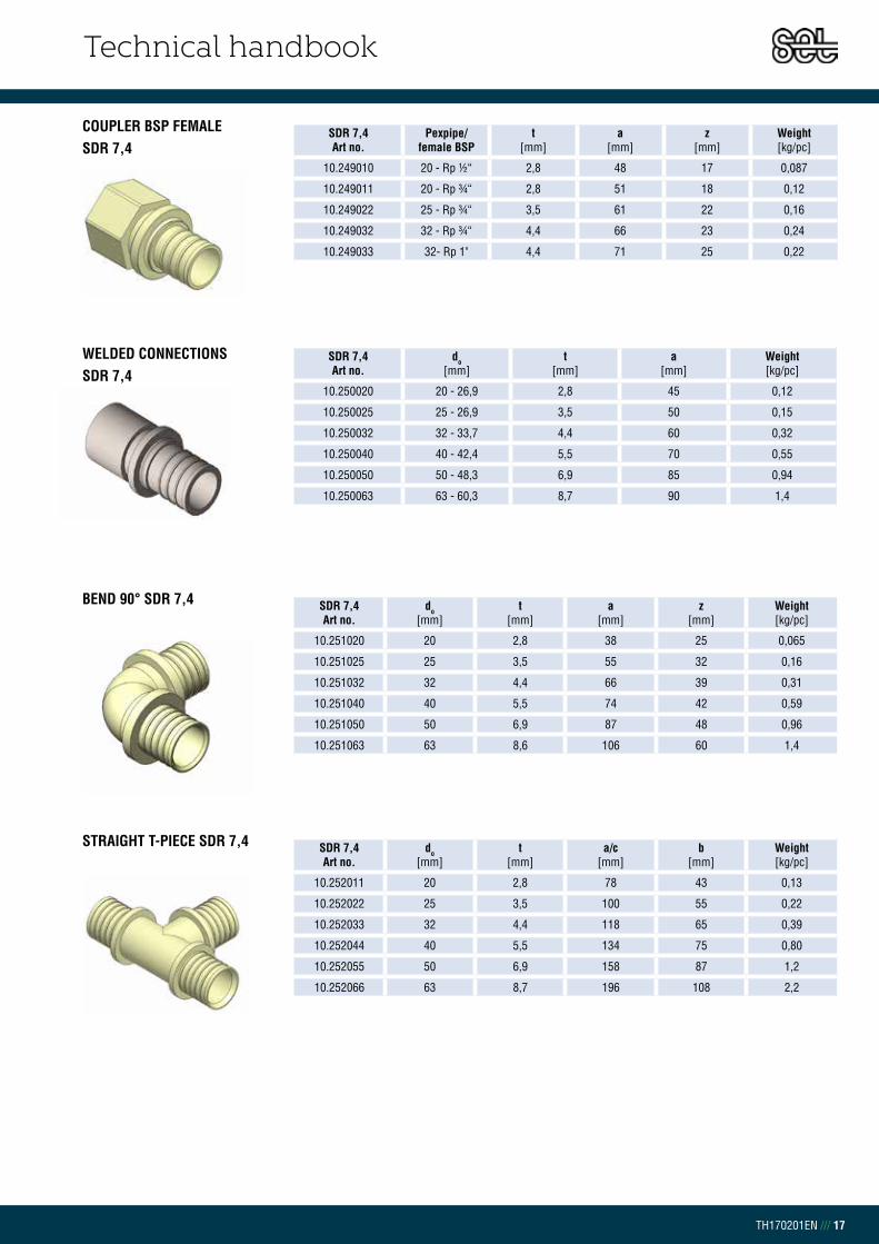
Technical handbook
TH170201EN /// 17
COUPLER BSP FEMALE SDR 7,4
SDR 7,4Art no.
Pexpipe/female BSP
t[mm]
a[mm]
z[mm]
Weight[kg/pc]
10.249010 20 - Rp ½“ 2,8 48 17 0,087
10.249011 20 - Rp ¾“ 2,8 51 18 0,12
10.249022 25 - Rp ¾“ 3,5 61 22 0,16
10.249032 32 - Rp ¾“ 4,4 66 23 0,24
10.249033 32- Rp 1" 4,4 71 25 0,22
WELDED CONNECTIONS SDR 7,4
SDR 7,4Art no.
do[mm]
t[mm]
a[mm]
Weight[kg/pc]
10.250020 20 - 26,9 2,8 45 0,12
10.250025 25 - 26,9 3,5 50 0,15
10.250032 32 - 33,7 4,4 60 0,32
10.250040 40 - 42,4 5,5 70 0,55
10.250050 50 - 48,3 6,9 85 0,94
10.250063 63 - 60,3 8,7 90 1,4
SDR 7,4Art no.
do[mm]
t[mm]
a[mm]
z[mm]
Weight[kg/pc]
10.251020 20 2,8 38 25 0,065
10.251025 25 3,5 55 32 0,16
10.251032 32 4,4 66 39 0,31
10.251040 40 5,5 74 42 0,59
10.251050 50 6,9 87 48 0,96
10.251063 63 8,6 106 60 1,4
BEND 90° SDR 7,4
STRAIGHT T-PIECE SDR 7,4 SDR 7,4Art no.
do[mm]
t[mm]
a/c[mm]
b[mm]
Weight[kg/pc]
10.252011 20 2,8 78 43 0,13
10.252022 25 3,5 100 55 0,22
10.252033 32 4,4 118 65 0,39
10.252044 40 5,5 134 75 0,80
10.252055 50 6,9 158 87 1,2
10.252066 63 8,7 196 108 2,2

Technical handbook
TH170201EN /// 18
SDR 7,4Art no.
do[mm]
a/c[mm]
b[mm]
Weight[kg/pc]
10.252121 25-20-25 98 47 0,19
10.252131 32-20-32 110 51 0,29
10.252132 32-25-32 110 59 0,34
10.252141 40-20-40 128 56 0,64
10.252142 40-25-40 132 67 0,64
10.252143 40-32-40 132 73 0,67
10.252151 50-20-50 132 63 0,76
10.252152 50-25-50 136 71 0,81
10.252153 50-32-50 138 76 0,88
10.252154 50-40-50 142 76 0,84
10.252162 63-25-63 160 76 1,3
10.252163 63-32-63 166 86 1,5
10.252164 63-40-63 180 90 1,6
10.252165 63-50-63 180 97 1,9
REDUCING T-PIECE SDR 7,4
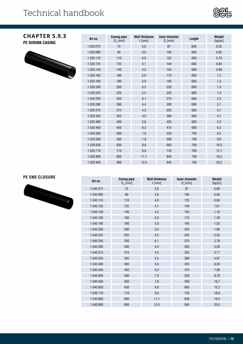
Technical handbook
TH170201EN /// 19
CHAPTER 5.9.3PE SHRINK CASING
Art no. Casing pipe Do [mm]
Wall thickness t [mm]
Inner diameter Di [mm] Length Weight
[kg/pc]
1.520.075 75 3,0 87 600 0,55
1.520.090 90 4,0 105 600 0,62
1.520.110 110 4,0 125 600 0,78
1.520.125 125 4,1 140 600 0,84
1.520.140 140 4,5 155 600 0,98
1.520.160 160 5,0 175 600 1,2
1.520.180 180 5,0 195 600 1,3
1.520.200 200 5,5 220 600 1,4
1.520.225 225 5,5 245 600 1,9
1.520.250 250 6,1 270 600 2,3
1.520.280 280 4,4 300 600 2,7
1.520.315 315 4,5 335 600 3,1
1.520.355 355 4,5 380 600 4,1
1.520.400 400 5,6 425 600 5,2
1.520.450 450 6,3 475 600 6,3
1.520.500 500 7,0 530 700 8,2
1.520.560 560 7,8 590 700 9,0
1.520.630 630 8,8 665 700 10,3
1.520.710 710 9,8 745 700 12,7
1.520.800 800 11,1 840 700 16,2
1.520.900 900 12,5 945 700 20,5
Art no. Casing pipe Do [mm]
Wall thickness t [mm]
Inner diameter Di [mm]
Weight[kg/pc]
1.540.075 75 3,0 87 0,66
1.540.090 90 4,0 105 0,90
1.540.110 110 4,0 125 0,94
1.540.125 125 4,1 140 1,01
1.540.140 140 4,5 155 1,18
1.540.160 160 5,0 175 1,39
1.540.180 180 5,0 195 1,52
1.540.200 200 5,5 220 1,66
1.540.225 225 5,5 245 2,22
1.540.250 250 6,1 270 2,78
1.540.280 280 4,4 300 3,28
1.540.315 315 4,5 335 3,77
1.540.355 355 4,5 380 4,87
1.540.400 400 5,6 425 6,26
1.540.450 450 6,3 475 7,56
1.540.500 500 7,0 530 9,78
1.540.560 560 7,8 590 10,7
1.540.630 630 8,8 665 15,2
1.540.710 710 9,8 745 18,8
1.540.800 800 11,1 840 19,4
1.540.900 900 12,5 945 20,5
PE END CLOSURE
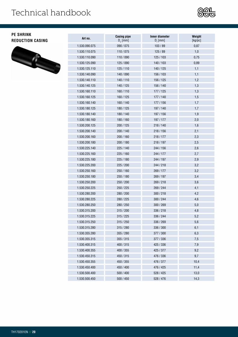
Technical handbook
TH170201EN /// 20
PE SHRINK REDUCTION CASING
Art no. Casing pipe Do [mm]
Inner diameter Di [mm]
Weight[kg/pc]
1.530.090.075 090 / 075 103 / 89 0,87
1.530.110.075 110 / 075 125 / 89 1,0
1.530.110.090 110 / 090 125 / 103 0,75
1.530.125.090 125 / 090 140 / 103 0,89
1.530.125.110 125 / 110 140 / 125 1,1
1.530.140.090 140 / 090 156 / 103 1,1
1.530.140.110 140 / 110 156 / 125 1,2
1.530.140.125 140 / 125 156 / 140 1,3
1.530.160.110 160 / 110 177 / 125 1,3
1.530.160.125 160 / 125 177 / 140 1,5
1.530.160.140 160 / 140 177 / 156 1,7
1.530.180.125 180 / 125 197 / 140 1,7
1.530.180.140 180 / 140 197 / 156 1,9
1.530.180.160 180 / 160 197 / 177 2,0
1.530.200.125 200 / 125 218 / 140 1,6
1.530.200.140 200 / 140 218 / 156 2,1
1.530.200.160 200 / 160 218 / 177 2,3
1.530.200.180 200 / 180 218 / 197 2,5
1.530.225.140 225 / 140 244 / 156 2,6
1.530.225.160 225 / 160 244 / 177 2,7
1.530.225.180 225 / 180 244 / 197 2,9
1.530.225.200 225 / 200 244 / 218 3,2
1.530.250.160 250 / 160 269 / 177 3,2
1.530.250.180 250 / 180 269 / 197 3,4
1.530.250.200 250 / 200 269 / 218 3,6
1.530.250.225 250 / 225 269 / 244 4,1
1.530.280.200 280 / 200 300 / 218 4,2
1.530.280.225 280 / 225 300 / 244 4,6
1.530.280.250 280 / 250 300 / 269 5,0
1.530.315.200 315 / 200 336 / 218 4,8
1.530.315.225 315 / 225 336 / 244 5,2
1.530.315.250 315 / 250 336 / 269 5,6
1.530.315.280 315 / 280 336 / 300 6,1
1.530.355.280 355 / 280 377 / 300 6,3
1.530.355.315 355 / 315 377 / 336 7,5
1.530.400.315 400 / 315 425 / 336 7,9
1.530.400.355 400 / 355 425 / 377 9,2
1.530.450.315 450 / 315 476 / 336 9,7
1.530.450.355 450 / 355 476 / 377 10,4
1.530.450.400 450 / 400 476 / 425 11,4
1.530.500.400 500 / 400 528 / 425 13,0
1.530.500.450 500 / 450 528 / 476 14,3

Technical handbook
TH170201EN /// 21
PE SHRINK REDUCTION CASING
PE ELECTRIC WELDING CASING
Art no. Casing pipe Do [mm]
Inner diameter Di [mm]
Weight[kg/pc]
1.530.560.400 560 / 400 - 9,47
1.530.560.450 560 / 450 - 10,2
1.530.560.500 560 / 500 - 11,1
1.530.630.450 630 / 450 - 11,7
1.530.630.500 630 / 500 - 12,6
1.530.630.560 630 / 560 - 13,8
1.530.710.500 710 / 500 - 14,6
1.530.710.560 710 / 560 - 15,8
1.530.710.630 710 / 630 - 17,3
1.530.800.560 800 / 560 - 18,2
1.530.800.630 800 / 630 - 19,7
1.530.800.710 800 / 710 - 21,7
1.530.900.630 900 / 630 - 22,0
1.530.900.710 900 / 710 - 24,1
1.530.900.800 900 / 800 - 26,4
Art no. Casing pipe do
Wall thickness
Inner diameter Di
Weight
1.512.090 90 4,0 105 0,62
1.512.110 110 4,0 125 0,78
1.512.125 125 4,1 140 0,84
1.512.140 140 4,5 155 0,98
1.512.160 160 5,0 175 1,2
1.512.180 180 5,0 195 1,3
1.512.200 200 5,0 220 1,4
1.512.225 225 5,5 245 1,9
1.512.250 250 6,1 270 2,3
1.512.280 280 4,4 300 2,7
1.512.315 315 4,5 335 3,1
1.512.355 355 4,5 380 4,1
1.512.400 400 5,6 425 5,2
1.512.450 450 6,3 475 6,3
1.512.500 500 7,0 530 8,2
1.512.560 560 7,8 590 9,0
1.512.630 630 8,8 665 10,3
1.512.710 710 9,8 745 12,7
1.512.800 800 11,1 840 16,2
1.512.900 900 12,5 945 20,5
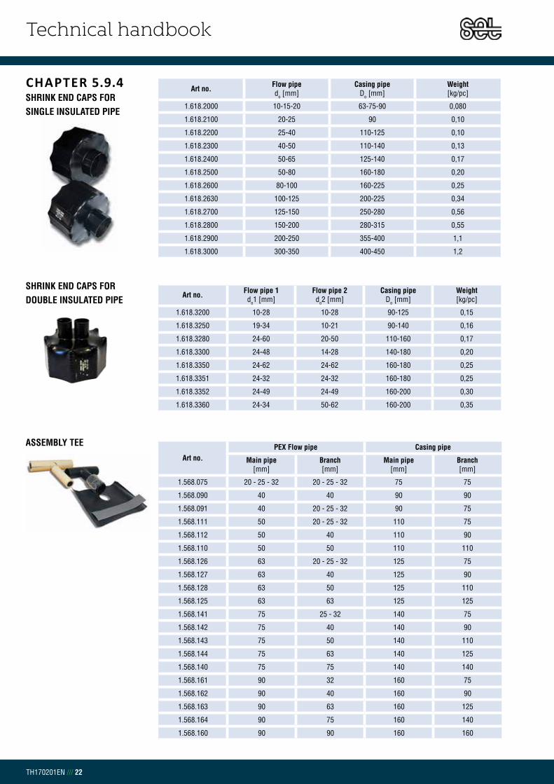
Technical handbook
TH170201EN /// 22
CHAPTER 5.9.4SHRINK END CAPS FOR SINGLE INSULATED PIPE
Art no. Flow pipedo [mm]
Casing pipeDo [mm]
Weight[kg/pc]
1.618.2000 10-15-20 63-75-90 0,080
1.618.2100 20-25 90 0,10
1.618.2200 25-40 110-125 0,10
1.618.2300 40-50 110-140 0,13
1.618.2400 50-65 125-140 0,17
1.618.2500 50-80 160-180 0,20
1.618.2600 80-100 160-225 0,25
1.618.2630 100-125 200-225 0,34
1.618.2700 125-150 250-280 0,56
1.618.2800 150-200 280-315 0,55
1.618.2900 200-250 355-400 1,1
1.618.3000 300-350 400-450 1,2
Art no.PEX Flow pipe Casing pipe
Main pipe [mm]
Branch[mm]
Main pipe [mm]
Branch[mm]
1.568.075 20 - 25 - 32 20 - 25 - 32 75 75
1.568.090 40 40 90 90
1.568.091 40 20 - 25 - 32 90 75
1.568.111 50 20 - 25 - 32 110 75
1.568.112 50 40 110 90
1.568.110 50 50 110 110
1.568.126 63 20 - 25 - 32 125 75
1.568.127 63 40 125 90
1.568.128 63 50 125 110
1.568.125 63 63 125 125
1.568.141 75 25 - 32 140 75
1.568.142 75 40 140 90
1.568.143 75 50 140 110
1.568.144 75 63 140 125
1.568.140 75 75 140 140
1.568.161 90 32 160 75
1.568.162 90 40 160 90
1.568.163 90 63 160 125
1.568.164 90 75 160 140
1.568.160 90 90 160 160
ASSEMBLY TEE
SHRINK END CAPS FOR DOUBLE INSULATED PIPE
Art no. Flow pipe 1do1 [mm]
Flow pipe 2do2 [mm]
Casing pipeDo [mm]
Weight[kg/pc]
1.618.3200 10-28 10-28 90-125 0,15
1.618.3250 19-34 10-21 90-140 0,16
1.618.3280 24-60 20-50 110-160 0,17
1.618.3300 24-48 14-28 140-180 0,20
1.618.3350 24-62 24-62 160-180 0,25
1.618.3351 24-32 24-32 160-180 0,25
1.618.3352 24-49 24-49 160-200 0,30
1.618.3360 24-34 50-62 160-200 0,35
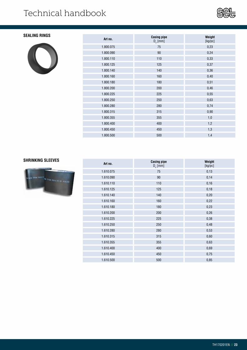
Technical handbook
TH170201EN /// 23
SEALING RINGS
SHRINKING SLEEVES
Art no. Casing pipeDo [mm]
Weight[kg/pc]
1.800.075 75 0,23
1.800.090 90 0,24
1.800.110 110 0,33
1.800.125 125 0,37
1.800.140 140 0,36
1.800.160 160 0,40
1.800.180 180 0,51
1.800.200 200 0,46
1.800.225 225 0,55
1.800.250 250 0,63
1.800.280 280 0,74
1.800.315 315 0,90
1.800.355 355 1,0
1.800.400 400 1,2
1.800.450 450 1,3
1.800.500 500 1,4
Art no. Casing pipeDo [mm]
Weight[kg/pc]
1.610.075 75 0,13
1.610.090 90 0,14
1.610.110 110 0,16
1.610.125 125 0,18
1.610.140 140 0,20
1.610.160 160 0,22
1.610.180 180 0,23
1.610.200 200 0,26
1.610.225 225 0,38
1.610.250 250 0,48
1.610.280 280 0,53
1.610.315 315 0,60
1.610.355 355 0,63
1.610.400 400 0,69
1.610.450 450 0,75
1.610.500 500 0,85

Technical handbook
TH170201EN /// 24
SHRINK SLEEVES FOR STEEL PIPE CANUSA-PLA
Art no. Casing pipeDO [mm]
CANUSA Number
Weight[kg/pc]
1.634.090 90 PLA-090-450-YE 0,28
1.634.115 115 PLA-115-450-YE 0,35
1.634.125 125 PLA-125-450-YE 0,41
1.634.160 160 PLA-160-450-YE 0,45
1.634.170 170 PLA-170-450-YE 0,52
1.634.200 200 PLA-200-450-YE 0,60
1.634.230 230 PLA-230-450-YE 0,61
1.634.280 280 PLA-280-450-YE 0,78
1.634.315 315 PLA-315-450-YE 0,88
Art no. Widthb [mm]
CANUSA Number
Length L [m]
Weight[kg/pc]
1.635.150 150 WLD-B-150-30 30 0,83
1.635.225 225 WLD-B-225-30 30 1,2
1.635.450 450 WLD-B-450-30 30 2,5
1.635.650 650 WLD-B-650-30 30 3,5
1.635.900 900 WLD-B-900-15 15 5,3
Art no. Widthb [mm]
CANUSA Number
Length L [m]
Weight[kg/pc]
1.637.100 100 CLW-B-100-15 15 0,33
LOCK STRIPS CANUSA CLW
REPAIR STRIPS CANUSA WLD-B
SHRINKING SHEETS FOR STEEL PIPE CANUSA-HCA Art no. Width
b [mm] CANUSA Number Length L [m]
Weight[kg/pc]
1.639.075 75 HCA-B-75-15 BK 15 0,10
1.639.110 110 HCA-B-100-15 15 0,20
SHRINK HOSE FOR STEEL PIPE CANUSA-PMA Art no. Width
b [mm] CANUSA Number Length L [m]
Weight[kg/pc]
1.634.040 40/15 PMA-40/15-1500-BK 1500 1,1
1.634.050 50/16 PMA-50/16-1500-BK 1500 1,1
1.634.060 60/35 PMA-60/35-915-BK 915 0,67
1.634.065 60/35 PMA-60/35-1500-BK 1500 1,1
1.634.070 70/25 PMA-70/25-1500-BK 1500 1,3
1.634.084 84/58 PMA-84/58-915-BK 915 1,1

Technical handbook
TH170201EN /// 25
CHAPTER 5.9.5FUSAPEX ELECTROFUSION SOCKET SDR 11 PEX
Art no. Do[mm]
D[mm]
Z[mm]
L[mm]
Weight[kg/pc]
10.130050 50 68 3 100 0,16
10.130063 63 82 3 118 0,25
10.130075 75 98 3 125 0,35
10.130090 90 117 3 135 0,65
10.130110 110 140 3 163 0,85
10.130125 125 157 3 173 1,1
FUSAPEX ELECTROFUSION BEND 90° SDR 11 PEX
Art no. Do[mm]
L[mm]
L1[mm]
L2[mm]
Weight[kg/pc]
10.131075 75 150 61 96 0,51
10.131090 90 202 70 111 0,86
10.131110 110 234 73 140 1,5
10.131125 125 271 81 163 2,3
FUSAPEX ELECTROFUSION REDUCER SDR 11 PEX
Art no. Do[mm]
L[mm]
L1[mm]
L2[mm]
Weight[kg/pc]
10.133090.075 90-75 132 71 61 0,29
10.133110.075 110-75 140 79 61 0,46
10.133110.090 110-90 150 79 71 0,49
10.133125.075 125-75 144 83 61 0,66
10.133125.090 125-90 154 83 71 0,66
10.133125.110 125-110 162 83 79 0,66
10.133160.075 160-75 156 95 61 1,3
10.133160.090 160-90 166 95 71 1,2
10.133160.110 160-110 174 95 79 1,2
10.133160.125 160-1125 178 95 83 1,2
FUSAPEX ELECTROFUSION TRANSITION FLANGE SDR 11 PEXFLANGE ACCORDING TO EN 1092
Art no. Do / DN Z[mm]
L[mm]
HF[mm]
LK[mm]
Weight[kg/pc]
10.135075 75/65 101 61 29 145 1,9
10.135090 90/80 110 71 29 160 2,1
10.135110 110/100 117 79 31 180 2,5
10.135125 125/100 130 83 38 180 2,8

Technical handbook
TH170201EN /// 26
FUSAPEX ELECTROFUSION T-PIECE SDR 11 PEX
FUSAPEX ELECTROFUSION ESM TRANSITION WITH AG SDR 11 PEX
Art no. DiameterD1-d1-D2 [mm]
L[mm]
L1[mm]
D1[mm]
L2[mm]
D2[mm]
H[mm]
Weight[kg/pc]
10.132050 50-50-50 155 49 68 49 68 155 0,38
10.132063 63-63-63 166 58 82 57 82 188 0,60
10.132075 75-75-75 187 61 97 62 96 187 1,1
10.132090 90-90-90 293 71 112 73 117 220 1,8
10.132110 110-110-110 328 72 143 79 139 296 3,4
10.132125 125-125-125 380 85 163 83 155 326 3,7
Art no. Pexpipe/male BSP
L[mm]
L1[mm]
L2[mm]
D2[mm]
Weight[kg/pc]
10.138050 50 - R 1 ½” 136 26 86 38 0,53
10.138063 63 - R 2” 160 31 101 48 0,90
10.138075 75 - R 2 ½” 171 34 46 51 1,5
FUSAPEX FLANGE SEAL SDR 11 PEX
Art no. Do/DN [mm]
D1[mm]
D2[mm]
s1[mm]
s2[mm]
10.136075 75/65 77 127 4 5
10.136090 98/80 89 142 4 5
10.136112 110/100 til 125/110 115 162 5 6
10.135125 125/100 130 83 38 180

Technical handbook
TH170201EN /// 27
CHAPTER 5.9.6PE WELDING PLUG
Art no. Weight[kg/pc]
1.591 0,010
Art no. Weight[kg/pc]
1.600.000 0,010
Art no. Volume [L]
Weight[kg/pc]
1.583.750 0,75 0,67
PE CLEANER (ETHANOL)
VENTILATION PLUG SEALING
PE-AIR VENTING PLUGArt no. Weight
[kg/pc]
1.592 0,010

Technical handbook
TH170201EN /// 28
CHAPTER 5.9.7PUR INSULATION SHELL
Art no. DN Outer diameter Do[ mm]
Inner diameter Di [mm]
Weight[kg/pc]
1.581.090.020 90/20 90 20 0,22
1.581.090.025 90/25 90 25 0,20
1.581.110.020 110/20 110 20 0,34
1.581.110.025 110/25 110 25 0,32
1.581.110.032 110/32 110 32 0,30
1.581.110.040 110/40 110 40 0,28
1.581.125.020 125/20 125 20 0,45
1.581.125.025 125/25 125 25 0,43
1.581.125.032 125/32 125 32 0,41
1.581.125.040 125/40 125 40 0,39
1.581.125.050 125/50 125 50 0,35
1.581.140.032 140/32 140 32 0,54
1.581.140.040 140/40 140 40 0,52
1.581.140.050 140/50 140 50 0,48
1.581.140.065 140/65 140 65 0,41
1.581.160.050 160/50 160 50 0,67
1.581.160.065 160/65 160 65 0,60
1.581.160.080 160/80 160 80 0,53
1.581.180.065 180/65 180 65 0,82
1.581.180.080 180/80 180 80 0,75
1.581.200.080 200/80 200 80 0,99
1.581.200.100 200/100 200 100 0,82
1.581.225.100 225/100 225 100 1,2
1.581.225.125 225/125 225 125 0,93
1.581.250.100 250/100 250 100 1,5
1.581.250.125 250/125 250 125 1,3
1.581.250.150 250/150 250 150 1,0
1.581.280.125 280/125 280 125 1,8
1.581.280.150 280/150 280 150 1,5
1.581.315.150 315/150 315 150 2,2
1.581.315.200 315/200 315 200 1,5
1.581.355.200 355/200 355 200 2,3
1.581.400.200 400/200 400 200 3,4
1.581.400.250 400/250 400 250 2,5
1.581.450.250 450/250 450 250 3,9
1.581.450.300 450/300 450 300 2,8
1.581.500.350 500/350 500 350 3,6
1.581.560.400 560/400 500 400 3,2
1.581.710.600 710/600 710 600 3,3

Technical handbook
TH170201EN /// 29
PUR INSULATION SHELL W/SOFT INNER LAYER
Art no. DN Outer diameter Do [ mm]
Inner diameter Di [mm]
Weight[kg/pc]
1.585.075.020 075/020 75 20 0,19
1.585.075.025 075/025 75 25 0,18
1.585.075.032 075/032 75 32 0,24
1.585.075.040 075/040 75 40 0,27
1.585.090.020 090/020 90 20 0,28
1.585.090.025 090/025 90 25 0,27
1.585.090.032 090/032 90 32 0,26
1.585.090.040 090/040 90 40 0,23
1.585.110.025 110/025 110 25 0,42
1.585.110.032 110/032 110 32 0,40
1.585.110.040 110/040 110 40 0,38
1.585.110.050 110/050 110 50 0,34
1.585.125.025 125/025 125 25 0,56
1.585.125.032 125/032 125 32 0,55
1.585.125.040 125/040 125 40 0,52
1.585.125.050 125/050 125 50 0,48
1.585.125.063 125/063 125 63 0,42
1.585.140.032 140/032 140 32 0,70
1.585.140.040 140/040 140 40 0,67
1.585.140.050 140/050 140 50 0,64
1.585.140.063 140/063 140 63 0,58
1.585.140.075 140/075 140 75 0,51
1.585.160.032 160/032 160 32 0,94
1.585.160.040 160/040 160 40 0,91
1.585.160.050 160/050 160 50 0,88
1.585.160.063 160/063 160 63 0,81
1.585.160.075 160/075 160 75 0,75
1.585.160.090 160/090 160 90 0,64
1.585.180.040 180/040 180 40 1,0
1.585.180.050 180/050 180 50 1,2
1.585.180.063 180/063 180 63 1,1
1.585.180.090 180/090 180 90 0,92
1.585.180.110 180/110 180 110 0,75
1.585.200.063 200/063 200 63 1,4
1.585.200.075 200/075 200 75 1,5
1.585.200.090 200/090 200 90 1,2
1.585.200.110 200/110 200 110 1,1
1.585.225.075 225/075 225 75 1,7
1.585.225.090 225/090 225 90 1,6
1.585.225.110 225/110 225 110 1,5
1.585.225.125 225/125 225 125 1,3
1.585.225.140 225/140 225 140 1,2
1.585.250.075 250/075 250 75 2,5
1.585.250.090 250/090 250 90 2,1
1.585.250.110 250/110 250 110 1,5
1.585.250.125 250/125 250 125 1,8

Technical handbook
TH170201EN /// 30
1.585.250.140 250/140 250 140 1,6
1.585.250.160 250/160 250 160 1,4
1.585.280.110 280/110 280 110 0,75
1.585.280.125 280/125 280 125 1,2
1.585.280.160 280/160 280 160 2,0
1.585.280.180 280/180 280 180 1,7
1.585.315.125 315/125 315 125 3,2
1.585.315.140 315/140 315 140 3,0
1.585.315.160 315/160 315 160 2,8
1.585.315.200 315/200 315 200 2,2
1.585.315.225 315/225 315 225 1,8
1.585.355.140 355/140 355 140 4,0
1.585.355.160 355/160 355 160 3,8
1.585.355.180 355/180 355 180 3,5
1.585.355.200 355/200 355 200 3,2
1.585.355.250 355/250 355 250 2,3
1.585.400.160 400/160 400 160 5,1
1.585.400.180 400/180 400 180 4,8
1.585.400.200 400/200 400 200 4,6
1.585.400.250 400/250 400 250 3,6
1.585.400.280 400/280 400 280 2,9
1.585.400.315 400/315 400 315 2,5
1.585.450.200 450/200 450 200 6,0
1.585.450.225 450/225 450 225 5,7
1.585.450.250 450/250 450 250 5,3
1.585.450.280 450/280 450 280 4,6
1.585.450.315 450/315 450 315 3,8
1.585.500.225 500/225 500 225 7,5
1.585.500.250 500/250 500 250 7,1
1.585.500.280 500/280 500 280 6,4
1.585.500.315 500/315 500 315 5,6
1.585.500.355 500/355 500 355 4,5
1.585.560.400 560/400 560 400 5,5
PUR INSULATION SHELL W/SOFT INNER LAYER

Technical handbook
TH170201EN /// 31
PUR INSULATION SHELL FOR DOUBLE PIPE
Art no. DN Outer diameter Do [ mm]
Inner diameter Di [mm]
Weight[kg/pc]
1.587.125.020 125/20-20 125 20-20 0,42
1.587.140.020 140/20-20 140 20-20 0,44
1.587.140.025 140/25-25 140 25-25 0,52
1.587.160.025 160/25-25 160 25-25 0,72
1.587.160.032 160/32-32 160 32-32 0,67
1.587.180.032 180/32-32 180 32-32 0,89
1.587.160.040 160/40-40 160 40-40 0,67
1.587.180.040 180/40-40 180 40-40 0,89
1.587.200.050 200/50-50 200 50-50 1,0
1.587.225.050 225/50-50 225 50-50 1,3
1.587.225.065 225/65-65 225 65-65 1,2
1.587.250.065 250/65-65 250 65-65 1,6
1.587.250.080 250/80-80 250 80-80 1,4
1.587.280.080 280/80-80 280 80-80 1,9
1.587.315.100 315/100-100 315 100-100 2,2
1.587.355.100 355/100-100 355 100-100 3,1
1.587.400.125 400/125-125 400 125-125 3,7
1.587.450.125 450/125-125 450 125-125 5,0
1.587.450.150 450/150-150 450 150-150 4,5
1.587.500.150 500/150-150 500 150-150 5,9
1.587.560.200 560/200-200 560 200-200 6,6
1.587.630.200 630/200-200 630 200-200 9,2

Technical handbook
TH170201EN /// 32
CHAPTER 5.9.8FOAM SUPPORT PAD
1000
200
0
1000
200
0 100
100
1
000
þennsluefniWEIGHT:
A3
SHEET 1 OF 1SCALE:1:20
DWG NO.
TITLE:
REVISIONDO NOT SCALE DRAWING
MATERIAL:
DATESIGNATURENAME
DEBUR AND BREAK SHARP EDGES
FINISH:UNLESS OTHERWISE SPECIFIED:DIMENSIONS ARE IN MILLIMETERSSURFACE FINISH:TOLERANCES: LINEAR: ANGULAR:
Q.A
MFG
APPV'D
CHK'D
DRAWN
Art no. Size[mm]
Weight[kg/m]
1.590.1000 2000 x 1000 x 40 4,0
1000
200
0
1000
200
0 100
100
1
000
þennsluefniWEIGHT:
A3
SHEET 1 OF 1SCALE:1:20
DWG NO.
TITLE:
REVISIONDO NOT SCALE DRAWING
MATERIAL:
DATESIGNATURENAME
DEBUR AND BREAK SHARP EDGES
FINISH:UNLESS OTHERWISE SPECIFIED:DIMENSIONS ARE IN MILLIMETERSSURFACE FINISH:TOLERANCES: LINEAR: ANGULAR:
Q.A
MFG
APPV'D
CHK'D
DRAWN
Art no. Width[mm]
Weight[kg/m]
1.590.2000 1000 -
1000
200
0
1000
200
0 100
100
1
000
þennsluefniWEIGHT:
A3
SHEET 1 OF 1SCALE:1:20
DWG NO.
TITLE:
REVISIONDO NOT SCALE DRAWING
MATERIAL:
DATESIGNATURENAME
DEBUR AND BREAK SHARP EDGES
FINISH:UNLESS OTHERWISE SPECIFIED:DIMENSIONS ARE IN MILLIMETERSSURFACE FINISH:TOLERANCES: LINEAR: ANGULAR:
Q.A
MFG
APPV'D
CHK'D
DRAWN
Art no. Size[mm]
Weight[kg/m]
1.590.010 100 x 100 x 1000 0,030 kg
UNDER PIPE SUPPORT
EXPANSION CASING
Art no. Dose [gr]
Casing pipe[mm]
Weight[kg/pc]
1.580.0250 250 75 0,25
1.580.0300 300 90 0,30
1.580.0400 400 110 0,40
1.580.0450 450 125 0,45
1.580.0550 550 140 0,55
1.580.0650 650 160 0,65
1.580.0850 850 180 0,85
1.580.1000 1000 200 1,0
1.580.1250 1250 225 1,3
1.580.1400 1400 250 1,4
1.580.1600 1600 280 1,6
1.580.1900 1900 315 1,9
1.580.2200 2200 355 2,2
1.580.2400 2400 400 2,4
1.580.3500 3500 - 3,5
1.580.5000 5000 - 5,0
PUR

Technical handbook
TH170201EN /// 33
CHAPTER 5.9.9DRILLING SET FOR BALL VALVE
1. Remove the insulation and clean the
steel pipe.
2. Weld the ball valve on the steel pipe.
3. Leave the ball valve open and attach
the drill at the ball valve.
4. Drill a hole through the steel pipe.
5. Close the ball valve and remove
the drill.
Now it is possible to connect a new
user to the district heating line
Art no.
1.935.000
GEAR FOR LONG STEM BALL VALVES
Art no.
1.934.000
Portable gear set for valves larger than DN250 when necessery to open and
close valves.
COMPRESSION SLEEVE TOOLSArt no. Outer diameter PEX pipe
do [mm]
9.6031 20-40
9.6030 50-125

Technical handbook
TH170201EN
Chapter 6 | Monitoring system
6.0 – Monitoring system ................................................................................... 1
6.1 – Nordic alarm monitoring system ........................................................ 1
6.2 – Alarm systems design ............................................................................. 2
TABLE OF CONTENT

Technical handbook
TH170201EN /// 1
CHAPTER 6.0MONITORING SYSTEM
A leak in the district heating pipe line is the main cause for premature failures.
Most of these failures can be traced to outer causes such as a leak through the
casing pipe or joint material. These failures may be avoided by monitoring the
district heating system and making the necessary measures as soon as the leak
has been detected.
The insulation foam damages and it´s insulation properties reduce consider-
ably when a leak occurs from the steel pipe or casing. Wet foam can last for years
at a low temperature but insulation thermal resistant is low. At high temperatures
the insulation foam will not last long.
The monitoring system can also find a small leak due to faulty installation of
the district heat pipe line and is therefore a certain deterrent for those working
with jointing and steel welding.
Set Pipes uses Nordic alarm monitoring system for all pre-insulated pipes and
fittings according to EN 14419 standard. The system is based on resistance
measurement between two steel wires and the steel service pipe. The wires which
are used are copper and tin plated copper wire 1,5 mm2. The purpose of the colour
difference is to make it easier to separate the wires during installation.
In production, all pipes and fittings are resistance measured according to EN 14419
and signed off accordingly by a qualified inspector.
Different monitoring equipment is available for the system, from on-site
measuring regularly for failures to a system which consistently monitors and results
are saved in a database. Set pipes can assist to provide suitable monitoring system
for customers.
CHAPTER 6.1NORDIC ALARM MONITORING SYSTEM

Technical handbook
TH170201EN /// 2
CHAPTER 6.2MONITORING SYSTEMS DESIGN
To be able to design and realized the potential of alarm monitoring connections
it is necessary to know the alarm system design. The following figure shows the
placement of the wires.
Please note. The below illustrations are only examples of fitting solutions.
Please contact Set Pipes technical team for further options.
FIGURE 6.2.190° Bend
FIGURE 6.2.4Transition fork
FIGURE 6.2.7Pre-insulated double steel pipe
FIGURE 6.2.2Pre-insulated single steel pipe
FIGURE 6.2.5Ball valve
FIGURE 6.2.8Double T- piece
FIGURE 6.2.3Transition F
FIGURE 6.2.6T-piece
FIGURE 6.2.9Double bend 90°

Technical handbook
TH170201EN
Chapter 7 | Instructions
7.0 – Instructions ................................................................................................ 1
7.1 – Pre-insulated steel pipes – Jointing PE shrink casing
and PUR insulation shell ........................................................................ 1
7.2 – Pre-insulated steel pipes - Jointing PE shrink casing
and PUR foam set .................................................................................... 3
7.3 – Elipex - Joint preparation PE shrink casing
and PUR insulation shell ........................................................................ 7
TABLE OF CONTENT

Technical handbook
TH170201EN /// 1
CHAPTER 7.1PRE-INSULATED STEEL PIPESJOINTING PE SHRINK CASING AND PUR INSULATION SHELL
CHAPTER 7.0INSTRUCTIONS
Clean thoroughly all dirt, moisture and grease from the casing pipe and steel pipe ends with a cloth and 99% Ethanol.
Gently straighten the monitoring system wires. Inspect the wire to see if they are damaged and that they are equal in length. Test the wires to see if they work properly.
Measure for the PUR insulation shell and cut to the correct length. Make sure there are no gaps between the insulation shell and insulation of the pipe.
Carve channels in the PUR insulation shell for the monitoring system wire.
Insert shell in the joint. Cut the wires to correct length.
Clean the wire ends with sandpaper and insert the wire connections.
Joint assembly should be performed by trained and certified personnel. Set Pipes
offers training courses regularly. Please contact Set Pipes technical department
for registering.
Pay special attention to all weather conditions and avoid water or moisture
during the insulation process. It is necessary to tent over the assembling area in
rain or wind.
Before starting, ensure all necessary tools and equipment are ready and on-
site. If joint preparation is done in a trench be sure it is wide enough to make the
work process safe and accessible. Ensure that foaming material is at the right
temperature (>18°C) and heat the shrink sleeve in cold conditions.
Before the steel is welded together the PE shrink casing and shrink sleeves,
including the white protective plastic, are slid on to the pre-insulated pipe.
Press wire connections with suitable pliers. To ensure connection, solder the wire connections.
Always measure both the pipes being laid and all connecting components by using an Ohm meter and megger before and after jointing. The insulation resistance should be higher than 500 MΩ. Results shall be documented to ensure the function and quality of the system.
1 2 3
4 5 6
7 8 9

Technical handbook
TH170201EN /// 2
Measure and mark with a marker the position of the PE shrink casing on casing pipe. Sand well the surface area sideways on the casing pipe with sand paper in coarseness of 40-60 where the PE shrink casing will be placed.
Slowly heat the surface of the casing pipe evenly with a soft flame of up to 60°C where the PE shrink casing will be situated. Slide the PE shrink casing over the joint and place it on the markings.
Slowly heat up the PE shrink casing evenly from the center and all around with a soft flame. Be sure the flame is moving constantly to prevent overheating and therefore damaging the PE shrink casing.
Slide the PE shrink sleeve over the joint and heat it slowly from the middle all around with a soft flame. While working towards sleeve ends tilt the flame 30° so air will not be trapped under the sleeve.
Clean the area where the shrink sleeve will be with ethanol and sand with sandpaper in coarseness of 40-60 across the pipeline direction.
Remove the white plastic protection from the PE shrink sleeve. Slowly heat the surface where the PE shrink sleeve will be situated with a flame of up to 60°C.
Use duct tape to fix the monitoring system wires down.
10 11 12
13 14 15
16
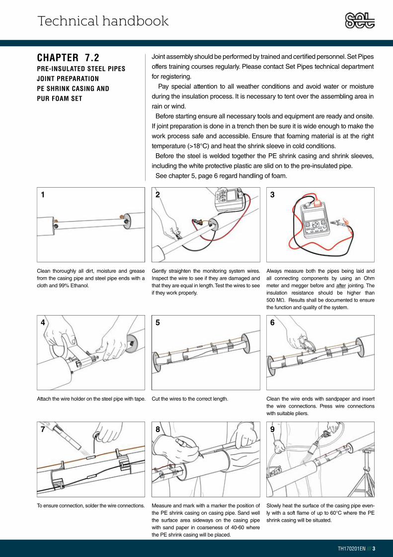
Technical handbook
TH170201EN /// 3
CHAPTER 7.2PRE-INSULATED STEEL PIPESJOINT PREPARATION PE SHRINK CASING AND PUR FOAM SET
Clean thoroughly all dirt, moisture and grease from the casing pipe and steel pipe ends with a cloth and 99% Ethanol.
Gently straighten the monitoring system wires. Inspect the wire to see if they are damaged and that they are equal in length. Test the wires to see if they work properly.
Always measure both the pipes being laid and all connecting components by using an Ohm meter and megger before and after jointing. The insulation resistance should be higher than 500 MΩ. Results shall be documented to ensure the function and quality of the system.
Attach the wire holder on the steel pipe with tape. Cut the wires to the correct length. Clean the wire ends with sandpaper and insert the wire connections. Press wire connections with suitable pliers.
To ensure connection, solder the wire connections. Measure and mark with a marker the position of the PE shrink casing on casing pipe. Sand well the surface area sideways on the casing pipe with sand paper in coarseness of 40-60 where the PE shrink casing will be placed.
Slowly heat the surface of the casing pipe even-ly with a soft flame of up to 60°C where the PE shrink casing will be situated.
1 2 3
4 5 6
7 2 98
Joint assembly should be performed by trained and certified personnel. Set Pipes
offers training courses regularly. Please contact Set Pipes technical department
for registering.
Pay special attention to all weather conditions and avoid water or moisture
during the insulation process. It is necessary to tent over the assembling area in
rain or wind.
Before starting ensure all necessary tools and equipment are ready and onsite.
If joint preparation is done in a trench then be sure it is wide enough to make the
work process safe and accessible. Ensure that foaming material is at the right
temperature (>18°C) and heat the shrink sleeve in cold conditions.
Before the steel is welded together the PE shrink casing and shrink sleeves,
including the white protective plastic are slid on to the pre-insulated pipe.
See chapter 5, page 6 regard handling of foam.

Technical handbook
TH170201EN /// 4
Slide the PE shrink casing over the joint and place it on the markings.
Slowly heat up the end of the PE shrink casing with even and light movements all the way around until the PE shrink casing has reduced to the casing pipe. Be sure the flame is moving constantly to prevent overheating.
Allow the PE shrink casing time to cool. Drill a hole as close to the edge of the pre-insulated pipe as possible for pouring of the PUR mixture.
Pressure test the PE shrink casing with 0,2 bar pressure for three minutes. Check for leaks with soapy water.
Clean the area where the shrink sleeve will be with ethanol and sand with sandpaper in coarse-ness of 40-60 across in the pipeline direction.
Slowly heat the surface of the casing pipe with a flame of up to 60°C where the PE shrink sleeve will be situated
Slide the PE shrink sleeve over the joint and remove the white plastic protection. Heat it slowly from the middle all around with a soft flame. While working towards sleeve ends tilt the flame 30° so air will not be trapped under the sleeve.
Allow the PE shrink sleeve time to cool down. Drill another hole for the PUR mixture as before. For quicker cleaning after insulating place a wide piece of duct tape before drilling.
For a pipe line that tilts, an air venting plug can be placed in the higher hole before pouring PUR foam into the lower hole.
10 11 12
13 14 15
1816 17

Technical handbook
TH170201EN /// 5
Allow to foam up through the plugs then hit the plugs down.
With a plug welding machine heat the welding plug for about 10 seconds before heating the drilled hole.
Remove the plug welding machine and press the plug down into the hole and hold for about 15 seconds.
Heat the surface of PE shrink casing with a light flame up to 60°C for the FOP sealing. Place the FOP sealing in place and heat slightly. Press lightly to release any air beneath
Press the plug welding machine down into the hole until well submerged, hold for about 10 seconds without pressure.
Note: Ensure the polyol and isocyanate is at the correct temperature approx. 20°C before mixing. Pour bottle B (Polyol) into bottle A (Iso-cyanate) and shake well for about 20 seconds.
Pour the PUR foam mixture rapidly in the lower drilled hole.
Place air venting plugs into both holes.
Leave the PUR foam material to dry for about 25 minutes. Remove the air venting plugs and clean all excess foam material from the surface. Make a chamber in the holes for the welding plugs and scrape the surface near the holes with sand paper or a scraper. Clean the area and the weld-ing plugs with Ethanol
19 20 21
2322 24
25 26 27

Technical handbook
TH170201EN /// 6
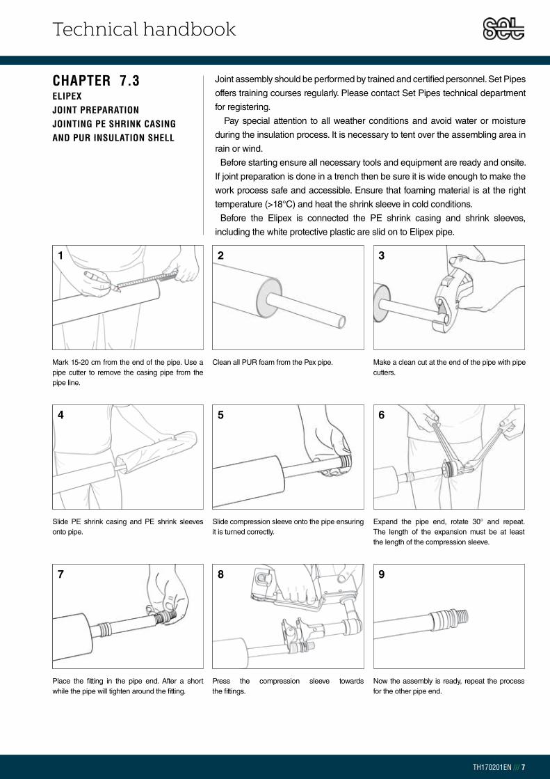
Technical handbook
TH170201EN /// 7
Joint assembly should be performed by trained and certified personnel. Set Pipes
offers training courses regularly. Please contact Set Pipes technical department
for registering.
Pay special attention to all weather conditions and avoid water or moisture
during the insulation process. It is necessary to tent over the assembling area in
rain or wind.
Before starting ensure all necessary tools and equipment are ready and onsite.
If joint preparation is done in a trench then be sure it is wide enough to make the
work process safe and accessible. Ensure that foaming material is at the right
temperature (>18°C) and heat the shrink sleeve in cold conditions.
Before the Elipex is connected the PE shrink casing and shrink sleeves,
including the white protective plastic are slid on to Elipex pipe.
CHAPTER 7.3ELIPEXJOINT PREPARATION JOINTING PE SHRINK CASING AND PUR INSULATION SHELL
Mark 15-20 cm from the end of the pipe. Use a pipe cutter to remove the casing pipe from the pipe line.
Clean all PUR foam from the Pex pipe. Make a clean cut at the end of the pipe with pipe cutters.
Slide PE shrink casing and PE shrink sleeves onto pipe.
Slide compression sleeve onto the pipe ensuring it is turned correctly.
Expand the pipe end, rotate 30° and repeat. The length of the expansion must be at least the length of the compression sleeve.
Place the fitting in the pipe end. After a short while the pipe will tighten around the fitting.
Press the compression sleeve towards the fittings.
Now the assembly is ready, repeat the process for the other pipe end.
1 2 3
4 5 6
7 8 9
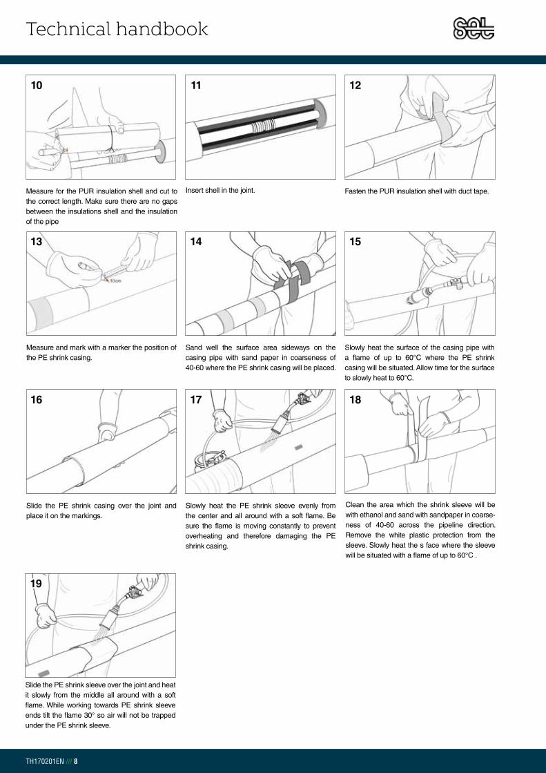
Technical handbook
TH170201EN /// 8
Measure for the PUR insulation shell and cut to the correct length. Make sure there are no gaps between the insulations shell and the insulation of the pipe
Insert shell in the joint. Fasten the PUR insulation shell with duct tape.
Measure and mark with a marker the position of the PE shrink casing.
Sand well the surface area sideways on the casing pipe with sand paper in coarseness of 40-60 where the PE shrink casing will be placed.
Slowly heat the surface of the casing pipe with a flame of up to 60°C where the PE shrink casing will be situated. Allow time for the surface to slowly heat to 60°C.
Clean the area which the shrink sleeve will be with ethanol and sand with sandpaper in coarse-ness of 40-60 across the pipeline direction. Remove the white plastic protection from the sleeve. Slowly heat the s face where the sleeve will be situated with a flame of up to 60°C .
Slide the PE shrink casing over the joint and place it on the markings.
Slowly heat the PE shrink sleeve evenly from the center and all around with a soft flame. Be sure the flame is moving constantly to prevent overheating and therefore damaging the PE shrink casing.
Slide the PE shrink sleeve over the joint and heat it slowly from the middle all around with a soft flame. While working towards PE shrink sleeve ends tilt the flame 30° so air will not be trapped under the PE shrink sleeve.
10 11 12
13 14 15
16 17 18
19

Technical handbook
TH170201EN
Chapter 8 | Documents/tables
8.0 – Documents/tables..................................................................................... 1
8.1 – Symbol table ............................................................................................. 1
8.2 –Conversions table ...................................................................................... 2
TABLE OF CONTENT

Technical handbook
TH170201EN /// 1
CHAPTER 8.0DOCUMENTS/TABLES
CHAPTER 8.1SYMBOL TABLE
SYMBOLS DEFINITION UNIT
Ai Cross section for the carrier pipe mm2
dO Outer diameter of the carrier pipe mm
di Inner diameter of the carrier pipe mm
da Outer diameter of flexible carrier pipe mm
DO Outer diameter of the casing pipe mm
Di Inner diameter of the casing pipe mm
t Wall thickness mm
ΔL Free expansion due to temperature difference mm
L Length m
H Pipe depth m
HCC
Distance from the surface to the middle of the pipe plus radius of the outer diameter of the casing m
Hm Height difference m
C Distance between parallel pipes m
Rmin Minimum bending radius m
Fa Free expansion force N/m
Fg Pipe weight when filled with water N/m
FN Resistance force of the pipe kN/m
T Temperature °C
TM Average temperature K
TVL Forward flow media temperature °C
TRL Return flow media temperature °C
ΔT Temperature difference K
q Total heat loss W/m
U Heat loss coefficient W/m·K
R Thermal resistance m·K/W
Coefficient of thermal conductivity W/m·K
Expansion coefficient K-1
E Modulus of elasticity N/mm2
Density Kg/m3
μ Friction coefficient -
Δ Difference (delta) -
Q Thermal requirement W
π Pi (22/7 = 3,14159...) -
P Pressure N/m2
zul Design stress N/mm2
y Yield strength N/mm2
e Specific soil weight kN/m2
V Average water velocity m/s
Mass flow m3/s (l/s)
g Acceleration due to gravity m/s2
cp Specific heat J/kg·K
ΔpPipe Pressure drop in carrier pipes Pa/m
k Resistance Coefficients for carrier pipes -
Viscosity m2/s
Re Reynolds number -
f Friction factor -
K0 The quiescent pressure correction factor -
TABLE 8.1.1Symbol table

Technical handbook
TH170201EN /// 2
W [J/s] kW kCAL/h HORSEPOWER (HP)
W [J/s] 1 1 x 10⁻³ 0,860 1,36 x 10⁻³
kW 1000 1 860 1,36
kCAL/h 1,16 1,16 x 10⁻³ 1 1,58 x 10⁻³
HORSEPOWER (HP) 735 0,735 632 1
EXAMPLE: 1 W = 0,860 kcal/h = 1,36 x 10⁻³ hö
Pa [N/m2] BAR mmVS atm [kP/cm2]
Pa [N/m2] 1 10 x 10-6 0,102 981 x 10-6
BAR 10 x 10-6 1 10197 0,981
mmVS 9,81 98,1 x 10⁻⁶ 1 100 x 10-6
atm [kP/cm2] 981 x 103 0,981 10 x 103 1
EXAMPLE: 1 mmVS = 9,81 Pa
1 m 1" (INCH) 1' (FEET) 1 MILE*
1 m 1 39,4 3,28 621 x 10-6
1" (TOMMA) 25,4 x 10⁻³ 1 83,3 x 10⁻³ 15,8 x 10⁻⁶
1' (FET) 0,305 12 1 189 x 10-6
1 MÍLA* 1609 63360 5280 1
* Imperial mile 1609 m. Nautical mile is 1852.
1 m3 1 L 1 US GAL. 1 UK GAL.
1 m3 1 1000 264,2 220
1 L 1 x 10⁻³ 1 0,264 0,220
1 US GAL. 3,79 x 10⁻³ 3,79 1 0,833
1 UK GAL. 4,55 x 10⁻³ 4,55 1,20 1
J [W·s] kW·h kCAL
J [W·s] 1 278 x 10-6 239 x 10-6
kW·h 3,60 x 10⁶ 1 860
kCAL 4187 1,16 x 10⁻³ 1
EXAMPLE: 1 kcal = 3,60 x 10⁶ W·s
CHAPTER 8.2CONVERSIONS TABLES
CONVERSION OF POWER UNITS
CONVERSION OF ENERGY UNITS
CONVERSION OF PRESSURE UNITS
CONVERSION OF LENGTH UNITS
CONVERSION OF VOLUME UNITS
TABLE 8.2.5Conversion of volume units
TABLE 8.2.4Conversion of length units
TABLE 8.2.3Conversion of pressure units
TABLE 8.2.2Conversion of energy units
TABLE 8.2.1Conversion of power units
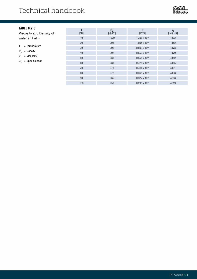
Technical handbook
TH170201EN /// 3
TABLE 8.2.6Viscosity and Density of
water at 1 atm
T[°C]
W[kg/m3] [m2/s]
CP[J/kg · K]
10 1000 1,307 x 10-6 4192
20 998 1,005 x 10-6 4182
30 996 0,802 x 10-6 4178
40 992 0,662 x 10-6 4179
50 988 0,555 x 10-6 4182
60 983 0,475 x 10-6 4185
70 978 0,414 x 10-6 4191
80 972 0,365 x 10-6 4198
90 965 0,327 x 10-6 4208
100 958 0,295 x 10-6 4219
T = Temperature
w = Density
= Viscosity
Cp = Specific heat