Technical Guide - WOLFen.wolf-heiztechnik.de/fileadmin/content/Downloads/Montage... · Technical...
28
Technical Guide Vacuum tube collector CRK-12 Wolf GmbH · Postfach 1380 · D-84048 Mainburg · Tel. +49 8751/74-0 · Fax +49 8751/741600 · Internet: www.wolf-heiztechnik.de 30 62 293 04/08 GB
Transcript of Technical Guide - WOLFen.wolf-heiztechnik.de/fileadmin/content/Downloads/Montage... · Technical...
Technical GuideVacuum tube collector CRK-12
Wolf GmbH · Postfach 1380 · D-84048 Mainburg · Tel. +49 8751/74-0 · Fax +49 8751/741600 · Internet: www.wolf-heiztechnik.de
30 62 293 04/08 GB
2 30 62 293_0408
1. General information ............................................................................................................................................ 3
2. Purpose and benefits .......................................................................................................................................... 4
3. Collector construction and function ..............................................................................................................5-7
4. Specification ........................................................................................................................................................ 8
4.1 Specification - CRK-12 .................................................................................................................................... 8
4.2 Pressure drop .................................................................................................................................................. 8
5. Output ................................................................................................................................................................... 9
6. Sizing the collector area .............................................................................................................................. 10-11
7. Regulating a solar heating system .................................................................................................................. 12
8. Sizing the collector connection lines .............................................................................................................. 12
9. Sizing the expansion vessel .......................................................................................................................13-14
10. Optional connections...................................................................................................................................15-16
11. System example ................................................................................................................................................ 17
11.1 System example - solar DHW heating ........................................................................................................ 17
11.2 System example - solar DHW heating with central heating backup ........................................................... 17
12. Installation information ................................................................................................................................18-24
12.1 Space requirement on pitched roofs ........................................................................................................... 18
12.2 System example - solar DHW heating with central heating backup ........................................................... 19
12.3 Weight and positioning of concrete slabs on flat roofs ............................................................................... 20
12.4 Space requirement for wall mounting (vertical) .......................................................................................... 21
12.5 Space requirement for wall mounting with angle frame pitch 45° or 60° .................................................. 22
12.6 Specifications .............................................................................................................................................. 23
12.7 Solar attic heating centre ............................................................................................................................ 24
13. Yield verification ...........................................................................................................................................25-26
14. Certificate Solar Keymark ................................................................................................................................ 27
Subject to technical modifications.Depictions, installation steps and technical details can vary as a result of ongoing development.
Manufacturer’s postal address:Wolf GmbH · Postfach 1380 · D-84048 Mainburg · Tel. +49 8751/74-0 · Fax +49 8751/741600 · Internet: www.wolf-heiztechnik.de
Copyright: All information in this technical document as well as in all drawings and technical descriptions made available remain our property and may not be reproduced without our prior written permission.
Index
330 62 293_0408
• Wherepossibleorientcollectorstowardssouth.• Ingeneral,alwaysfittheheaderatthetop.• Toassuretheself-cleaningeffect,aminimumroofpitchof15°isrecommendedforrooftop and flat roof installations.• Onlyremovethewhiteprotectivefoilonthevacuumtubesafterthesystemhasbeencommissioned.• Only use hard soldered connections or clamping ring fittings in the solar heating circuit.• ThermallyinsulatepiperunsinaccordancewiththeEnEV[Germany].Ensurethematerialistemperature-
resistant(150°C)andUV-resistant(linesroutedexternally).• Onlyfillthesolarheatingsystemwith"Tyfocor-LS"processmedium.• Thevacuumcollectorsarehail-prooftoDINEN12975-2.Nevertheless,werecommendincludingdamage
resultingfromstormandhailinyourpropertyinsurance.Ourmaterialwarrantyexcludessuchlosses.• ObserveallcurrentsafetyregulationsasdefinedbyDIN,DINEN,DVGW,TRFandVDE[orlocalregulations].• Solarcollectorsaresubjecttocountry-specificnotificationorpermits.• Installation,maintenanceandrepairworkmustonlybecarriedoutbyauthorisedtrainedpersonnel.• Anelectricallyconductiveconnectionofthepipeworkofthesolarcircuitshouldbeimplementedinthelower
partofthebuildinginaccordancewithVDE[orlocalregulations].Theconnectionofthesolarheatingsystemto an existing or new lightning protection system or to the building‘s equipotential bonding must only be implemented by authorised trained personnel.
Standards, regulations and EC DirectivesRegulation Description Installation on roofsDIN18338 VOB1): Covering and sealing roofsDIN18339 VOB1): PlumbingDIN18451 VOB1): ScaffoldingDIN1055,Part4and5 Assumedloadsonbuildings;windloadsandsnowloads Connection of solar heating systemsDINEN12975-1 Solarheatingsystemsandtheircomponents-Collectors Part 1: General requirementsDINEN12976-1 Solarheatingsystemsandtheircomponents-Pre-assembledsystems Part1:Generalrequirements;GermanversionDINENV12977-1 Solarheatingsystemsandtheircomponents-Bespokesystems Part1:Generalrequirements;GermanversionDIN4757-2 Solaheatingsystemswithorganicheattransfermedia; Safety equipment requirements Installation and equipment of DHW cylinders DIN1988 TechnicalrulesforDHWinstallations(TRWI)DIN4753-11 DHWcylindersandDHWheatingsystemsforpotableandservicewater Requirements, identifications, equipment levels and testingDIN18380 VOB1): Heating systems and central DHW heating systemsDIN18381 VOB1): Gas, water and waste water installations inside buildingsDIN18421 VOB1): Thermal insulation of technical systemsAVB2) WaterDVGWW551 DHWheatingandconductingsystems; Technical pasteurisation measures Electrical connectionDINVDE0100 Creatinghighvoltagesystemswithratedvoltagesupto1000VDINVDE0185 LightningprotectionsystemVDE0190 MainequipotentialbondingofelectricalsystemsDINVDE0855 Aerialsystems-tobeappliedanalogouslyDIN18382 VOB1):Lowandmediumvoltagewithratedvoltagesupto36kV
Important requirements for the installation of solar collector systems: 1)VOBorderregardingthepaymentofconstruction work - Part C: General technical terms of contract for construction work.2) Tender documentation for construction work in building construction, giving particular attention to residential buildings.
1. General information
4 30 62 293_0408
Intelligent construction and installation:• Suitableforinstallationonpitchedandflatroofs,aswellasfreestandinginstallationandinstallationonwalls.• Fortheheatingofpotablewaterandheatingwater,forthepartialheatingofswimmingpoolwater,aswellas
for cooling.• Upto15m2 aperture area can be connected in series.• Excellentdesign.• Shortinstallationtimesthroughfullypre-assembledcollectorunitsandeasy,flexibleinstallationsetsforrooftop
and flat roof installation.• Easyconnectionstoenableextensionwithadditionalcollectorssidebysidethroughpre-assembledfittings.
Noadditionalpipeworkorextensivethermalinsulationrequired.• Solarflowandreturncanbeinstalledeitherontheleft or right of the collector.• Tubescanbechangedwithoutdrainingthecollectorcircuit-"dryconnection".• Easyconnectionofhydrauliclinesthroughclampingringfittings.
Operational reliability:• Highoperationalreliabilityandalongservicelifethroughtheuseofhigh-gradecorrosionresistantmaterials,
such as thick-walled borosilicate glass, copper and aluminium with anti-corrosion coating.• Permanentvacuuminthetubesastheconnectionissolelyfromglasstoglass,i.e.noglass-metalunion.
Pure glass-glass connection as with a Thermos flask.• Highoperationalreliabilitythrough"dryconnection"ofthevacuumtubestothesolarcircuit.
Recycling:All parts can be recycled and reused.
Return:At the end of their useful life these collectors can be returned to Wolf GmbH. These collectors must be clearly identified(e.g.as"scrap")andbedeliveredexpensespaidduringbusinesshours.Allcollectormaterialsareeithercorrectly recycled or disposed of by Wolf GmbH.
Packaging:For optimum environmental responsibility, please return the cardboard packaging to the resources cycle via authorisedcollectionpoints[whereappropriate].Ifrequired,recycletheheattransfermediumviaauthoriseddepositories.
Energy yield and output:• Extremelyhighenergyyieldfromasmallgrosscollectorarea.• Thecircularabsorbersurfaceofeachtubeensuresanidealorientationtowardsthesunatalltimes.• Exceptionallyhighsolarcoverageispossible.• Highefficiencythroughhighlyselectivelycoatedabsorber.• Thevacuumtubesefficientlyreducethethermallossesofasolarcollector,asthevacuumisdevoidofair
thatcouldtransporttheheatfromtheabsorbersurfacetotheexternalglasstubethatissubjecttoweatherinfluences.
• Theheattransfermediumischannelleddirectlythroughapipewithoutanintermediateheatexchangerinsidethe collector.
• Thetubescollectnotonlythedirectbutalsothediffuseinsolationwithoptimumefficiencyatdifferentanglesofirradiation, thanks to the circular absorber.
• TheCPCmirrorandthedirectflowthroughthevacuumtubecontributesubstantiallytotheextremelyhighenergy yield.
• Thebestpossiblethermalinsulationisprovidedbythevacuum,resultinginhighlevelsofefficiency,particularly in winter and with low insolation.
• Alsoidealforlow-flowsystemswithstratificationheatingandcentralheatingbackup.
2. Purpose and benefits
530 62 293_0408
Historic roots - the invention of the Thermos flaskThe Scottish physicist James Dewar invented a dual-walled vessel with a vacuum-isolated space between the two chambers in 1893 - the Thermos flask.Asearlyas1909,EmmetinventedvacuumtubesbasedontheThermosflaskprincipleforturningsolarenergyinto useful energy. His patents from that time are still the basis for the most advanced vacuum tube technology today.However, the efficiency of the tried and trusted Thermos flask principle was only raised to the highest level by means of advanced coating technology and highly selective layers.
Current technologyThe Wolf vacuum tube collector is comprised of three main components that are fully assembled:
• vacuumtubes • CPCmirror • headerboxwithheattransferunit
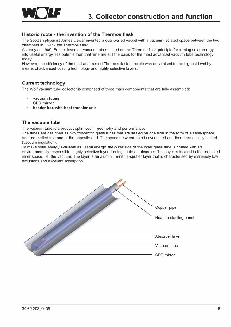
The vacuum tubeThe vacuum tube is a product optimised in geometry and performance.The tubes are designed as two concentric glass tubes that are sealed on one side in the form of a semi-sphere, and are melted into one at the opposite end. The space between both is evacuated and then hermetically sealed (vacuum insulation).To make solar energy available as useful energy, the outer side of the inner glass tube is coated with an environmentally responsible, highly selective layer, turning it into an absorber. This layer is located in the protected inner space, i.e. the vacuum. The layer is an aluminium-nitrite-sputter layer that is characterised by extremely low emissions and excellent absorption.
Copper pipe
Heat conducting panel
Absorber layer
Vacuumtube
CPC mirror
3. Collector construction and function
6 30 62 293_0408
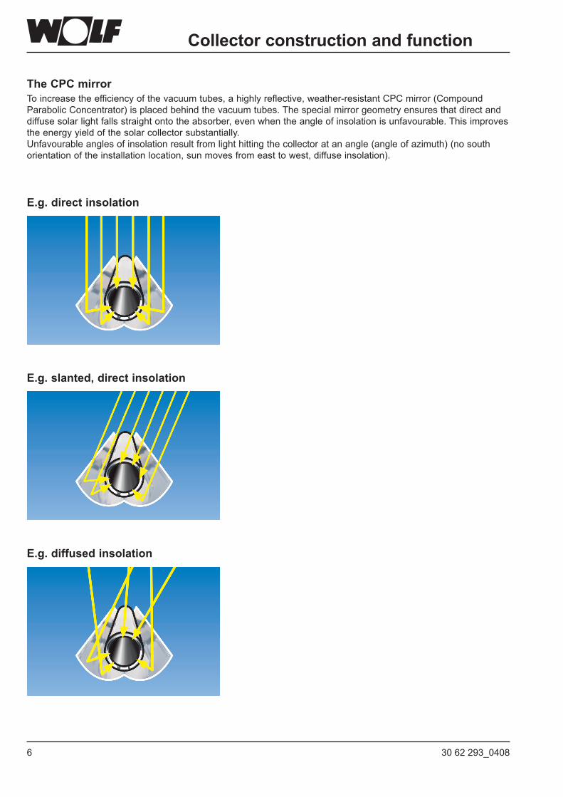
The CPC mirrorTo increase the efficiency of the vacuum tubes, a highly reflective, weather-resistant CPC mirror (Compound Parabolic Concentrator) is placed behind the vacuum tubes. The special mirror geometry ensures that direct and diffuse solar light falls straight onto the absorber, even when the angle of insolation is unfavourable. This improves the energy yield of the solar collector substantially.Unfavourable angles of insolation result from light hitting the collector at an angle (angle of azimuth) (no south orientation of the installation location, sun moves from east to west, diffuse insolation).
E.g. direct insolation
E.g. slanted, direct insolation
E.g. diffused insolation
Collector construction and function
730 62 293_0408
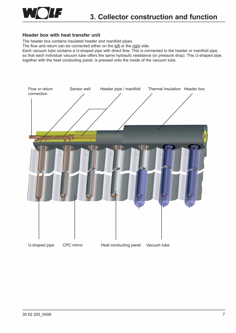
HeaderboxwithheattransferunitThe header box contains insulated header and manifold pipes.The flow and return can be connected either on the left or the right side.EachvacuumtubecontainsaU-shapedpipewithdirectflow.Thisisconnectedtotheheaderormanifoldpipe,so that each individual vacuum tube offers the same hydraulic resistance (or pressure drop). This U-shaped pipe, together with the heat conducting panel, is pressed onto the inside of the vacuum tube.
U-shaped pipe CPC mirror
Header boxFlow or return connection
Thermal insulation
Heat conducting panel
Header pipe / manifoldSensor well
Vacuumtube
3. Collector construction and function
8 30 62 293_0408
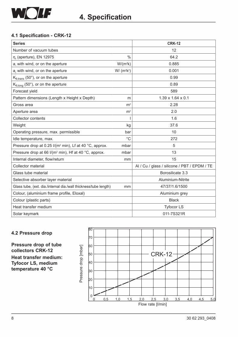
4.1 Specification - CRK-12
4.2 Pressure drop
Pressure drop of tube collectors CRK-12Heat transfer medium: Tyfocor LS, medium temperature 40 °C
Flowrate[l/min]
Pressuredrop[m
bar]
4. Specification
Series CRK-12Numberofvacuumtubes 12
η0(aperture),EN12975 % 64.2
a1 with wind, or on the aperture W/(m2k) 0.885
a2 with wind, or on the aperture W/ (m2k2) 0.001
Kθ,trans (50°), or on the aperture 0.99
Kθ,long (50°), or on the aperture 0.89
Forecast yield 589
Patterndimensions(LengthxHeightxDepth) m 1.39 x 1.64 x 0.1
Gross area m2 2.28
Aperture area m2 2.0
Collector contents l 1.6
Weight kg 37.6
Operatingpressure,max.permissible bar 10
Idle temperature, max. °C 272
Pressure drop at 0.25 l/(m2min),Lfat40°C,approx. mbar 5
Pressure drop at 66 l/(m2 min), Hf at 40 °C, approx. mbar 13
Internal diameter, flow/return mm 15
Collector material Al/Cu/glass/silicone/PBT/EPDM/TE
Glass tube material Borosilicate 3.3
Selective absorber layer material Aluminium-Nitrite
Glass tube, (ext. dia./internal dia./wall thickness/tube length) mm 47/37/1.6/1500
Colour,(aluminiumframeprofile,Eloxal) Aluminium grey
Colour (plastic parts) Black
Heat transfer medium TyfocorLS
Solar keymark 011-7S321R
930 62 293_0408
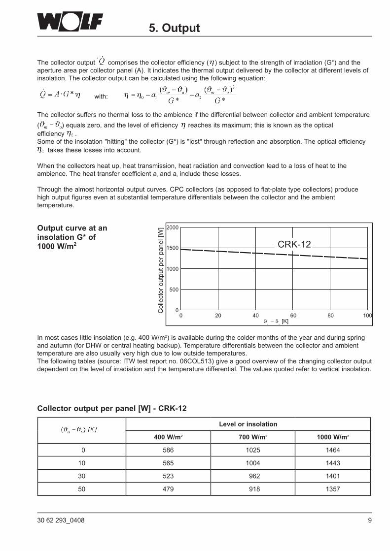
The collector output · comprises the collector efficiency ( )subjecttothestrengthofirradiation(G*)andtheaperture area per collector panel (A). It indicates the thermal output delivered by the collector at different levels of insolation. The collector output can be calculated using the following equation:
with:
The collector suffers no thermal loss to the ambience if the differential between collector and ambient temperature ( ) equals zero, and the level of efficiency reachesitsmaximum;thisisknownastheoptical efficiency .Someoftheinsolation"hitting"thecollector(G*)is"lost"throughreflectionandabsorption.Theopticalefficiency
takes these losses into account.
When the collectors heat up, heat transmission, heat radiation and convection lead to a loss of heat to the ambience. The heat transfer coefficient a1 and a2 include these losses.
Through the almost horizontal output curves, CPC collectors (as opposed to flat-plate type collectors) produce high output figures even at substantial temperature differentials between the collector and the ambient temperature.
Collectoroutputperpanel[W
]
5. Output
Output curve at an insolation G* of 1000 W/m2
In most cases little insolation (e.g. 400 W/m2) is available during the colder months of the year and during spring and autumn (for DHW or central heating backup). Temperature differentials between the collector and ambient temperature are also usually very high due to low outside temperatures. Thefollowingtables(source:ITWtestreportno.06COL513)giveagoodoverviewofthechangingcollectoroutputdependent on the level of irradiation and the temperature differential. The values quoted refer to vertical insolation.
Collector output per panel [W] - CRK-12
Level or insolation
400 W/m2 700 W/m2 1000 W/m2
0 586 1025 1464
10 565 1004 1443
30 523 962 1401
50 479 918 1357
10 30 62 293_0408
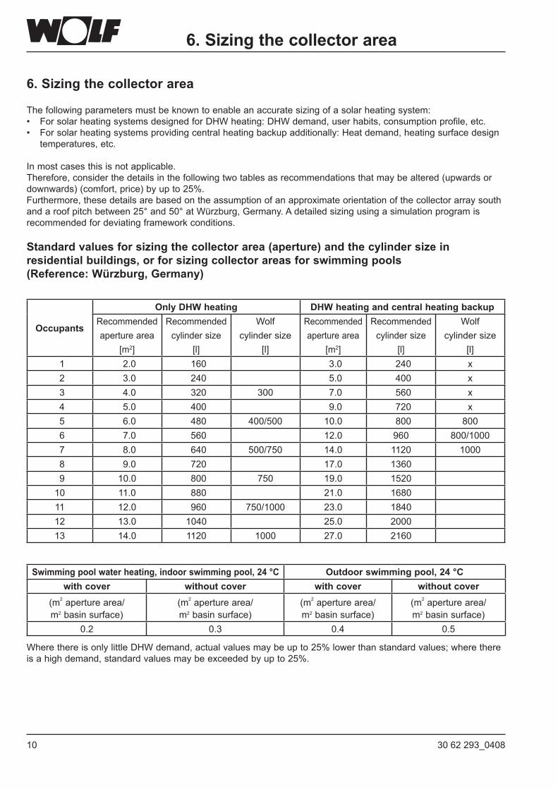
6. Sizing the collector area
The following parameters must be known to enable an accurate sizing of a solar heating system:• ForsolarheatingsystemsdesignedforDHWheating:DHWdemand,userhabits,consumptionprofile,etc.• Forsolarheatingsystemsprovidingcentralheatingbackupadditionally:Heatdemand,heatingsurfacedesign temperatures, etc.
In most cases this is not applicable. Therefore, consider the details in the following two tables as recommendations that may be altered (upwards or downwards) (comfort, price) by up to 25%.Furthermore, these details are based on the assumption of an approximate orientation of the collector array south and a roof pitch between 25° and 50° at Würzburg, Germany. A detailed sizing using a simulation program is recommended for deviating framework conditions.
Standard values for sizing the collector area (aperture) and the cylinder size in residentialbuildings,orforsizingcollectorareasforswimmingpools (Reference: Würzburg, Germany)
6. Sizing the collector area
Occupants
Only DHW heating DHW heating and central heating backupRecommended aperture area
[m2]
Recommended cylinder size
[l]
Wolf cylinder size
[l]
Recommended aperture area
[m2]
Recommended cylinder size
[l]
Wolf cylinder size
[l] 1 2.0 160 3.0 240 x 2 3.0 240 5.0 400 x 3 4.0 320 300 7.0 560 x 4 5.0 400 9.0 720 x 5 6.0 480 400/500 10.0 800 800 6 7.0 560 12.0 960 800/1000 7 8.0 640 500/750 14.0 1120 1000 8 9.0 720 17.0 1360 9 10.0 800 750 19.0 152010 11.0 880 21.0 168011 12.0 960 750/1000 23.0 184012 13.0 1040 25.0 200013 14.0 1120 1000 27.0 2160
Swimmingpoolwaterheating,indoorswimmingpool,24°C Outdoorswimmingpool,24°Cwithcover withoutcover withcover withoutcover
(m2 aperture area/ m2 basin surface)
(m2 aperture area/ m2 basin surface)
(m2 aperture area/ m2 basin surface)
(m2 aperture area/ m2 basin surface)
0.2 0.3 0.4 0.5
WherethereisonlylittleDHWdemand,actualvaluesmaybeupto25%lowerthanstandardvalues;wherethereis a high demand, standard values may be exceeded by up to 25%.
1130 62 293_0408
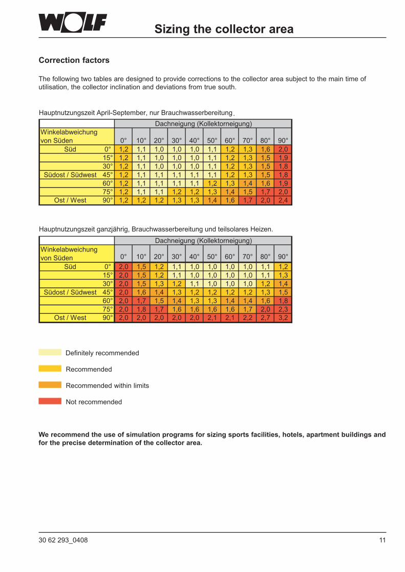
Correction factors
Thefollowingtwotablesaredesignedtoprovidecorrectionstothecollectorareasubjecttothemaintimeofutilisation, the collector inclination and deviations from true south.
Definitely recommended
Recommended
Recommended within limits
Notrecommended
We recommend the use of simulation programs for sizing sports facilities, hotels, apartment buildings and for the precise determination of the collector area.
Sizing the collector area
12 30 62 293_0408
7. Regulating a solar heating system
Thesolarcontrolunitfortubecollectorsystemsshouldoffera"Start-upfunction".This"Start-upfunction"preventsan excessive temperature differential between the actual temperature at the collector sensor and the temperature atthelower/centralpartofthetube.The"Start-up"(starting)ofthepumpshouldoccurapprox.twotothreetimesper minute for 3-5 seconds when a temperature rise is detected at the collector sensor, to channel hot heat transfer medium to the measuring point. Wolf solar panel SM2, part no. 27 44 296
7. Regulating a solar heating system 8. Sizing the collector connection lines
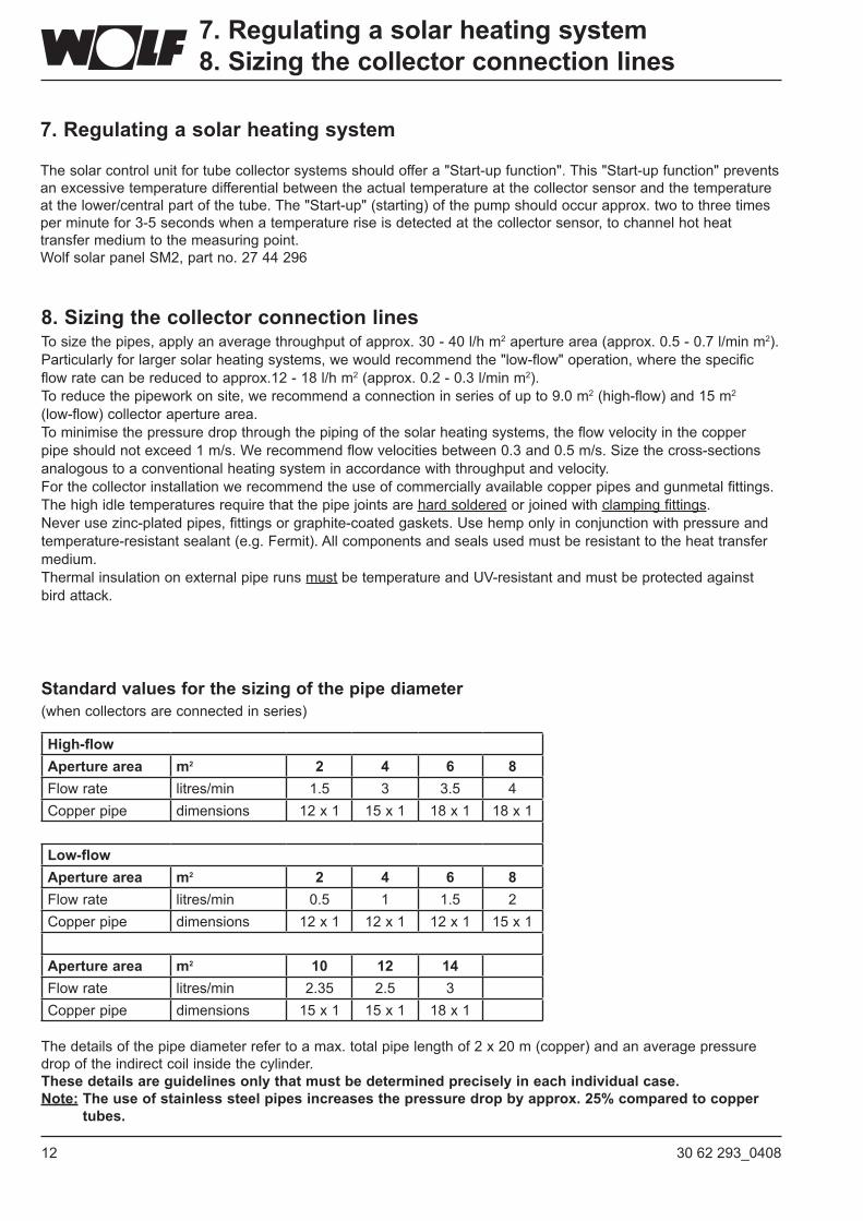
8. Sizing the collector connection linesTo size the pipes, apply an average throughput of approx. 30 - 40 l/h m2 aperture area (approx. 0.5 - 0.7 l/min m2). Particularlyforlargersolarheatingsystems,wewouldrecommendthe"low-flow"operation,wherethespecificflow rate can be reduced to approx.12 - 18 l/h m2 (approx. 0.2 - 0.3 l/min m2). To reduce the pipework on site, we recommend a connection in series of up to 9.0 m2 (high-flow) and 15 m2 (low-flow) collector aperture area.To minimise the pressure drop through the piping of the solar heating systems, the flow velocity in the copper pipe should not exceed 1 m/s. We recommend flow velocities between 0.3 and 0.5 m/s. Size the cross-sections analogous to a conventional heating system in accordance with throughput and velocity. For the collector installation we recommend the use of commercially available copper pipes and gunmetal fittings.Thehighidletemperaturesrequirethatthepipejointsarehard solderedorjoinedwithclamping fittings.Neverusezinc-platedpipes,fittingsorgraphite-coatedgaskets.Usehemponlyinconjunctionwithpressureandtemperature-resistant sealant (e.g. Fermit). All components and seals used must be resistant to the heat transfer medium.Thermal insulation on external pipe runs mustbetemperatureandUV-resistantandmustbeprotectedagainstbird attack.
Standard values for the sizing of the pipe diameter (when collectors are connected in series)
The details of the pipe diameter refer to a max. total pipe length of 2 x 20 m (copper) and an average pressure drop of the indirect coil inside the cylinder.These details are guidelines only that must be determined precisely in each individual case. Note: The use of stainless steel pipes increases the pressure drop by approx. 25% compared to copper
tubes.
High-flowAperture area m2 2 4 6 8Flow rate litres/min 1.5 3 3.5 4Copper pipe dimensions 12 x 1 15 x 1 18 x 1 18 x 1
Low-flowAperture area m2 2 4 6 8Flow rate litres/min 0.5 1 1.5 2Copper pipe dimensions 12 x 1 12 x 1 12 x 1 15 x 1
Aperture area m2 10 12 14Flow rate litres/min 2.35 2.5 3Copper pipe dimensions 15 x 1 15 x 1 18 x 1
1330 62 293_0408
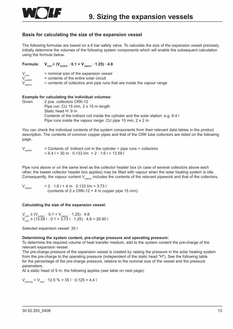
Basis for calculating the size of the expansion vessel
The following formulae are based on a 6 bar safety valve. To calculate the size of the expansion vessel precisely, initially determine the volumes of the following system components which will enable the subsequent calculation using the formula below.
Formula: Vnom ≥(Vsystem · 0.1 + Vvapour · 1.25) · 4.8
Vnom = nominal size of the expansion vesselVsystem = contents of the entire solar circuitVvapour = contents of collectors and pipe runs that are inside the vapour range
Example for calculating the individual volumes:Given: 2 pce. collectors CRK-12 Pipe run: CU 15 mm, 2 x 15 m length Static head H: 9 m Contents of the indirect coil inside the cylinder and the solar station: e.g. 6.4 l Pipe runs inside the vapour range: CU pipe 15 mm, 2 x 2 m You can check the individual contents of the system components from their relevant data tables in the product description. The contents of common copper pipes and that of the CRK tube collectors are listed on the following page.
Vsystem = Contents of: Indirect coil in the cylinder + pipe runs + collectors = 6.4 l + 30 m · 0.133 l/m + 2 · 1.6 l = 13.59 l
Pipe runs above or on the same level as the collector header box (in case of several collectors above each other, the lowest collector header box applies) may be filled with vapour when the solar heating system is idle. Consequently,thevapourcontentVvapour includes the contents of the relevant pipework and that of the collectors.
Vvapour = 2 · 1.6 l + 4 m · 0.133 l/m = 3.73 l (contents of 2 x CRK-12 + 4 m copper pipe 15 mm)
Calculating the size of the expansion vessel:
Vnom ≥(Vsystem·0.1+Vvapour · 1.25) · 4.8Vnom ≥ (13.59 l · 0.1 + 3.73 l · 1.25) · 4.8 = 28.90 l
Selected expansion vessel: 35 l
Determining the system content, pre-charge pressure and operating pressure:To determine the required volume of heat transfer medium, add to the system content the pre-charge of the relevant expansion vessel.The pre-charge pressure of the expansion vessel is created by raising the pressure in the solar heating system fromthepre-chargetotheoperatingpressure(independentofthestatichead"H").Seethefollowingtablefor the percentage of the pre-charge pressure, relative to the nominal size of the vessel and the pressure parameters.At a static head of 9 m, the following applies (see table on next page):
Vprechrg=Vnom · 12.5 % = 35 l · 0.125 = 4.4 l
9. Sizing the expansion vessels
14 30 62 293_0408
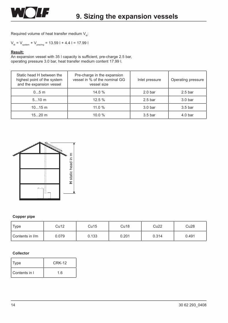
Required volume of heattransfermediumVttl:
Vttl=Vsystem+Vprechrg = 13.59 l + 4.4 l = 17.99 l
Result:An expansion vessel with 35 l capacity is sufficient, pre-charge 2.5 bar,operating pressure 3.0 bar, heat transfer medium content 17.99 l.
H s
tatic
hea
d in
m
9. Sizing the expansion vessels
Static head H between the highest point of the system and the expansion vessel
Pre-charge in the expansion vessel in % of the nominal GG
vessel sizeInlet pressure Operatingpressure
0...5 m 14.0 % 2.0 bar 2.5 bar
5...10 m 12.5 % 2.5 bar 3.0 bar
10...15 m 11.0 % 3.0 bar 3.5 bar
15...20 m 10.0 % 3.5 bar 4.0 bar
Copper pipe
Type Cu12 Cu15 Cu18 Cu22 Cu28
Contents in l/m 0.079 0.133 0.201 0.314 0.491
Collector
Type CRK-12
Contents in l 1.6
1530 62 293_0408
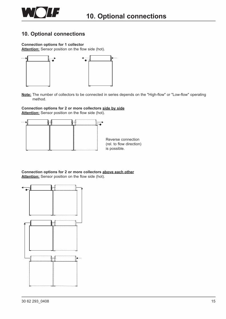
10. Optional connections
Connection options for 1 collectorAttention: Sensor position on the flow side (hot).
Note: Thenumberofcollectorstobeconnectedinseriesdependsonthe"High-flow"or"Low-flow"operatingmethod.
Connection options for 2 or more collectors side by sideAttention: Sensor position on the flow side (hot).
Connection options for 2 or more collectors above each otherAttention: Sensor position on the flow side (hot).
Reverse connection (rel. to flow direction) is possible.
10. Optional connections
16 30 62 293_0408
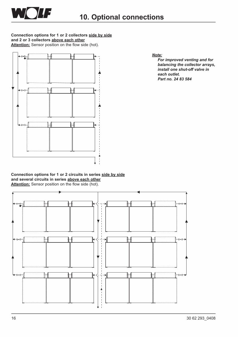
Connection options for 1 or 2 collectors side by side and 2 or 3 collectors above each otherAttention: Sensor position on the flow side (hot).
Connection options for 1 or 2 circuits in series side by side and several circuits in series above each otherAttention: Sensor position on the flow side (hot).
Note: For improved venting and for
balancing the collector arrays, install one shut-off valve in each outlet. Part no. 24 83 584
10. Optional connections
1730 62 293_0408
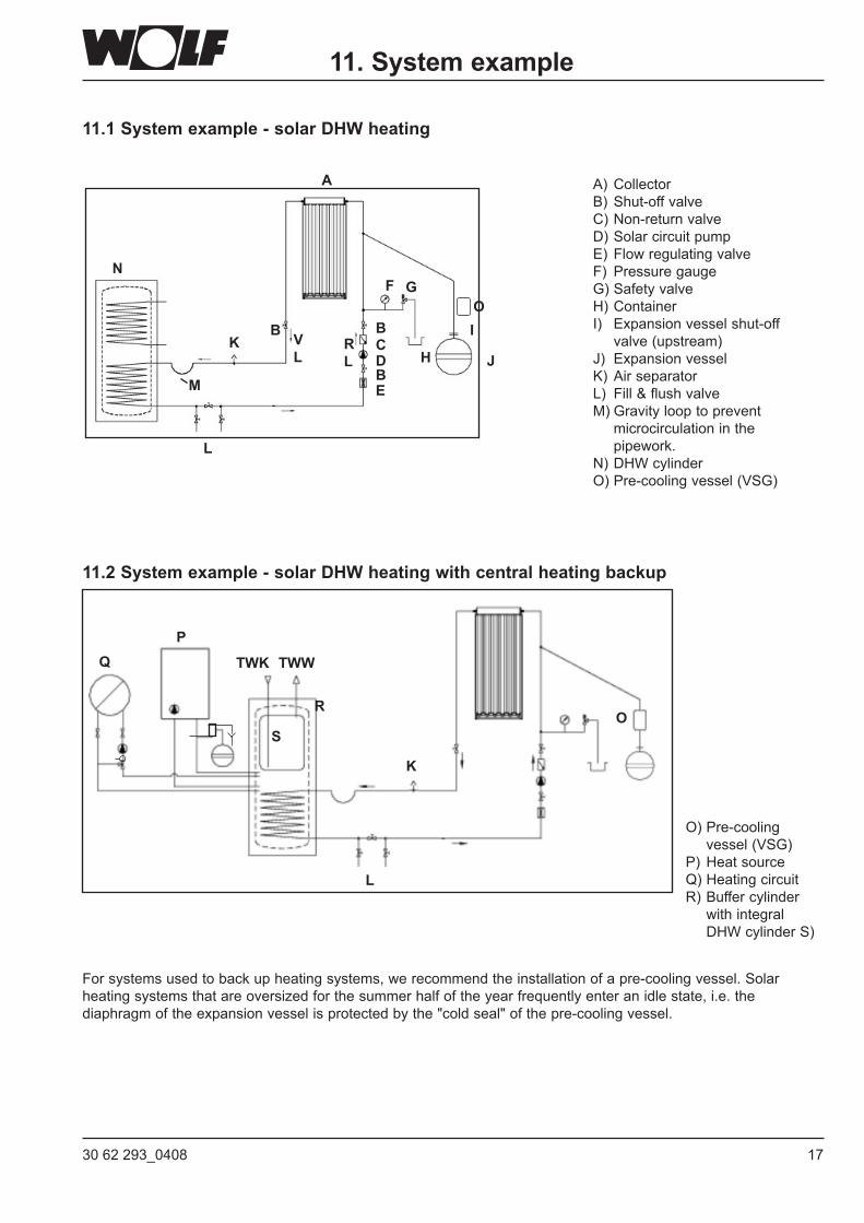
A) Collector B) Shut-off valveC)Non-returnvalveD) Solar circuit pumpE)FlowregulatingvalveF) Pressure gaugeG) Safety valveH) ContainerI) Expansionvesselshut-off valve (upstream)J) ExpansionvesselK) Air separatorL) Fill&flushvalveM) Gravity loop to prevent
microcirculation in the pipework.
N)DHWcylinderO)Pre-coolingvessel(VSG)
11. System example
11.1 System example - solar DHW heating
11.2Systemexample-solarDHWheatingwithcentralheatingbackup
For systems used to back up heating systems, we recommend the installation of a pre-cooling vessel. Solar heating systems that are oversized for the summer half of the year frequently enter an idle state, i.e. the diaphragmoftheexpansionvesselisprotectedbythe"coldseal"ofthepre-coolingvessel.
R L
V L
M
N
L
KH
B B
E
C
BD J
I
GF
A
O
OR
TWK TWW
S
PQ
K
L
O)Pre-cooling vessel(VSG)P) Heat source Q) Heating circuit R) Buffer cylinder
with integral DHW cylinder S)
18 30 62 293_0408
12. Installation information
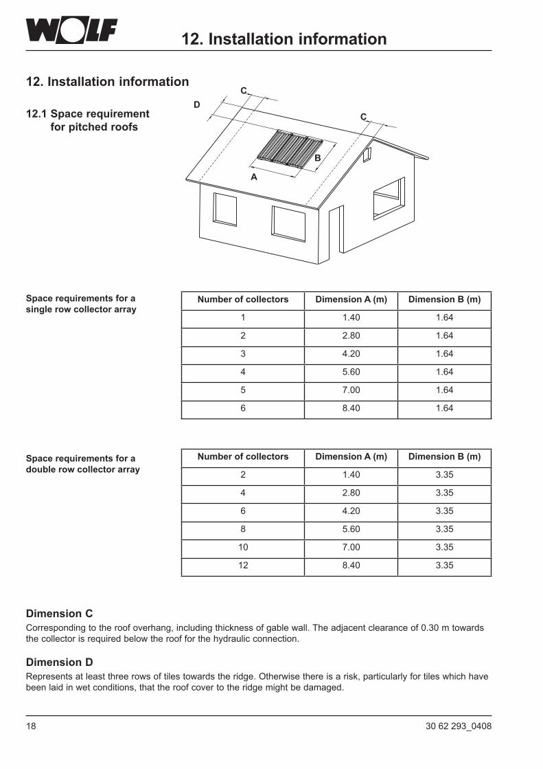
12.1 Space requirement for pitched roofs
B
A
DC
C
12. Installation information
Number of collectors Dimension A (m) Dimension B (m)
1 1.40 1.64
2 2.80 1.64
3 4.20 1.64
4 5.60 1.64
5 7.00 1.64
6 8.40 1.64
Number of collectors Dimension A (m) Dimension B (m)
2 1.40 3.35
4 2.80 3.35
6 4.20 3.35
8 5.60 3.35
10 7.00 3.35
12 8.40 3.35
Dimension CCorrespondingtotheroofoverhang,includingthicknessofgablewall.Theadjacentclearanceof0.30mtowardsthe collector is required below the roof for the hydraulic connection.
Dimension DRepresentsatleastthreerowsoftilestowardstheridge.Otherwisethereisarisk,particularlyfortileswhichhavebeen laid in wet conditions, that the roof cover to the ridge might be damaged.
Space requirements for a singlerowcollectorarray
Space requirements for a doublerowcollectorarray
1930 62 293_0408
AB
C
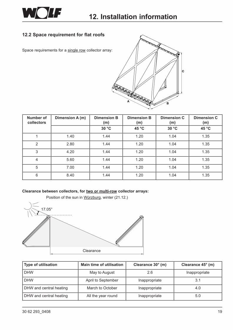
12.2 Space requirement for flat roofs
Space requirements for a single row collector array:
Clearance
12. Installation information
Number of collectors
Dimension A (m) Dimension B (m)
Dimension B (m)
Dimension C (m)
Dimension C (m)
30 °C 45 °C 30 °C 45 °C
1 1.40 1.44 1.20 1.04 1.35
2 2.80 1.44 1.20 1.04 1.35
3 4.20 1.44 1.20 1.04 1.35
4 5.60 1.44 1.20 1.04 1.35
5 7.00 1.44 1.20 1.04 1.35
6 8.40 1.44 1.20 1.04 1.35
Type of utilisation Main time of utilisation Clearance 30° (m) Clearance 45° (m)
DHW May to August 2.6 Inappropriate
DHW April to September Inappropriate 3.1
DHW and central heating MarchtoOctober Inappropriate 4.0
DHW and central heating All the year round Inappropriate 5.0
Clearancebetweencollectors,fortwoormulti-row collector arrays:Position of the sun in Würzburg, winter (21.12.)
17.05°
20 30 62 293_0408
12. Installation information
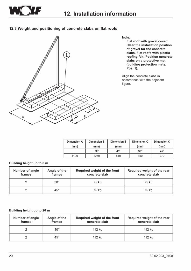
Note: Flatroofwithgravelcover:
Clear the installation position of gravel for the concrete slabs.Flatroofswithplasticroofing felt: Position concrete slabs on a protective mat (building protection mats, Pos. 1).
Align the concrete slabs in accordancewiththeadjacentfigure.
12.3 Weight and positioning of concrete slabs on flat roofs
A BC
C
Dimension A (mm)
Dimension B (mm)
Dimension B (mm)
Dimension C (mm)
Dimension C (mm)
30° 45° 30° 45°1100 1050 810 350 270
Number of angle frames
Angle of the frames
Requiredweightofthefrontconcrete slab
Requiredweightoftherearconcrete slab
2 30° 112 kg 112 kg
2 45° 112 kg 112 kg
Building height up to 20 m
Number of angle frames
Angle of the frames
Requiredweightofthefrontconcrete slab
Requiredweightoftherearconcrete slab
2 30° 75 kg 75 kg
2 45° 75 kg 75 kg
Building height up to 8 m
2130 62 293_0408
12. Installation information
B
A
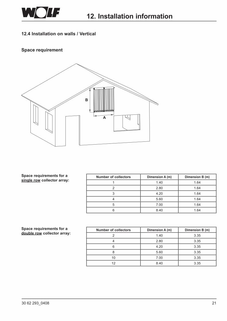
12.4Installationonwalls/Vertical
Space requirement
Number of collectors Dimension A (m) Dimension B (m)2 1.40 3.354 2.80 3.356 4.20 3.358 5.60 3.3510 7.00 3.3512 8.40 3.35
Space requirements for a doublerow collector array:
Number of collectors Dimension A (m) Dimension B (m)1 1.40 1.642 2.80 1.643 4.20 1.644 5.60 1.645 7.00 1.646 8.40 1.64
Space requirements for a singlerow collector array:
22 30 62 293_0408
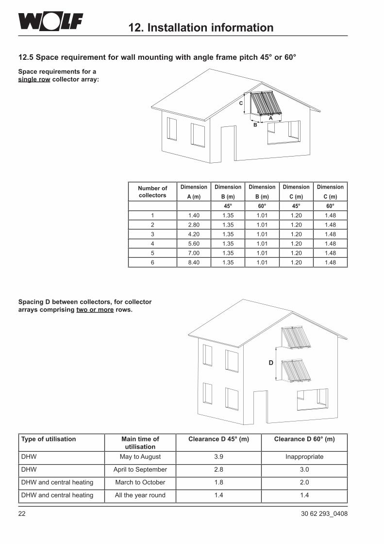
12.5Spacerequirementforwallmountingwithangleframepitch45°or60°
D
SpacingDbetweencollectors,forcollectorarrays comprising twoormorerows.
A
C
B
12. Installation information
Type of utilisation Main time of utilisation
Clearance D 45° (m) Clearance D 60° (m)
DHW May to August 3.9 Inappropriate
DHW April to September 2.8 3.0
DHW and central heating MarchtoOctober 1.8 2.0
DHW and central heating All the year round 1.4 1.4
Number of collectors
Dimension A (m)
Dimension B (m)
Dimension B (m)
Dimension C (m)
Dimension C (m)
45° 60° 45° 60°1 1.40 1.35 1.01 1.20 1.482 2.80 1.35 1.01 1.20 1.483 4.20 1.35 1.01 1.20 1.484 5.60 1.35 1.01 1.20 1.485 7.00 1.35 1.01 1.20 1.486 8.40 1.35 1.01 1.20 1.48
Space requirements for a singlerow collector array:
2330 62 293_0408
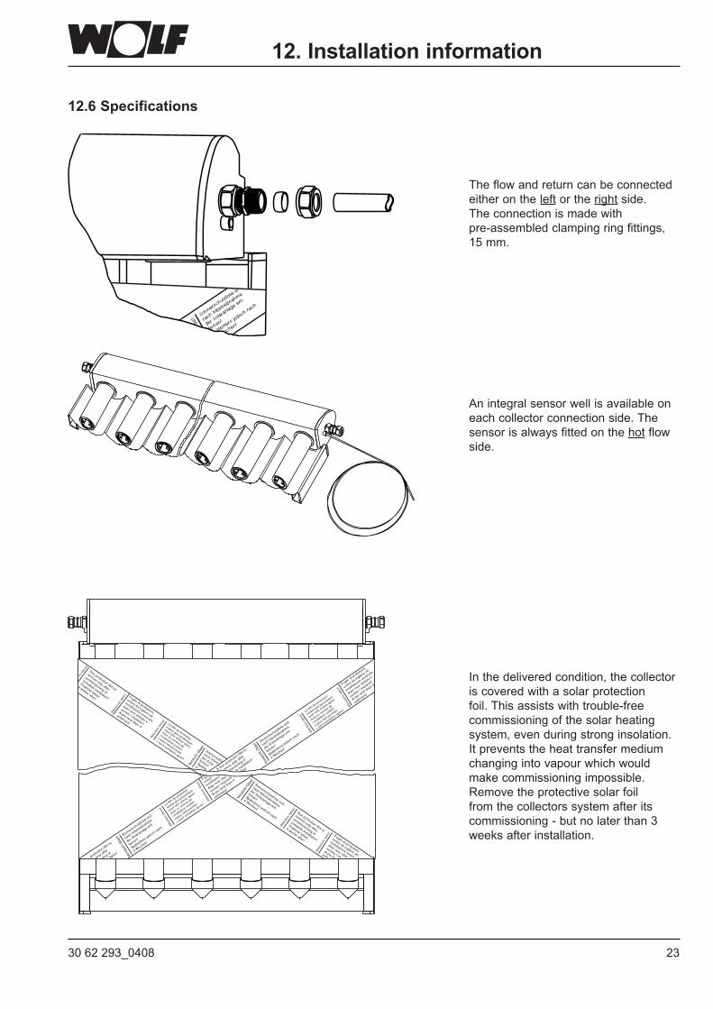
12.6 Specifications
The flow and return can be connected either on the left or the right side.The connection is made with pre-assembled clamping ring fittings, 15 mm.
An integral sensor well is available on each collector connection side. The sensor is always fitted on the hot flow side.
In the delivered condition, the collector is covered with a solar protection foil. This assists with trouble-free commissioning of the solar heating system, even during strong insolation. It prevents the heat transfer medium changing into vapour which would make commissioning impossible. Remove the protective solar foil from the collectors system after its commissioning - but no later than 3 weeks after installation.
12. Installation information
24 30 62 293_0408
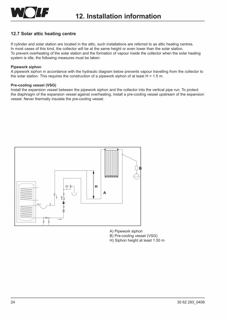
12.7 Solar attic heating centre
If cylinder and solar station are located in the attic, such installations are referred to as attic heating centres.In most cases of this kind, the collector will be at the same height or even lower than the solar station.To prevent overheating of the solar station and the formation of vapour inside the collector when the solar heating system is idle, the following measures must be taken:
PipeworksiphonA pipework siphon in accordance with the hydraulic diagram below prevents vapour travelling from the collector to the solar station. This requires the construction of a pipework siphon of at least H = 1.5 m.
Pre-cooling vessel (VSG)Install the expansion vessel between the pipework siphon and the collector into the vertical pipe run. To protect the diaphragm of the expansion vessel against overheating, install a pre-cooling vessel upstream of the expansion vessel.Neverthermallyinsulatethepre-coolingvessel.
A) Pipework siphonB)Pre-coolingvessel(VSG)H) Siphon height at least 1.50 m
HA
B
12. Installation information
2530 62 293_0408
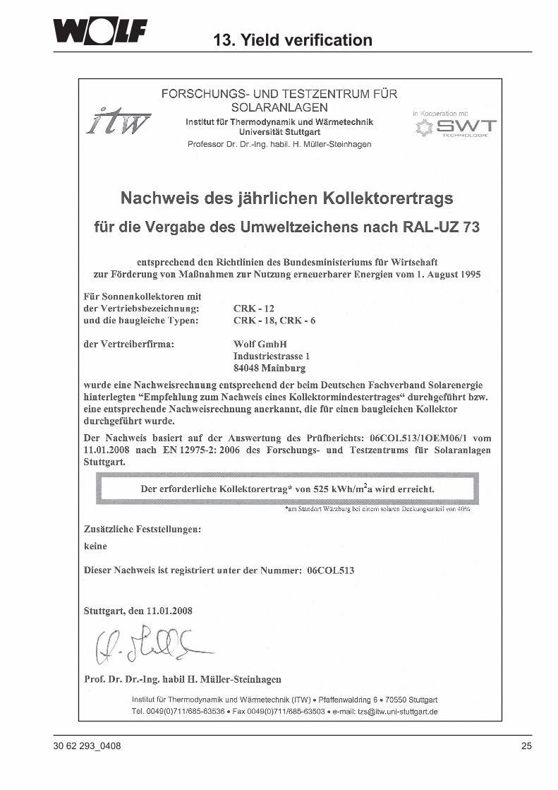
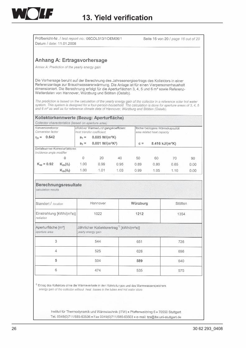
13. Yield verification
26 30 62 293_0408
13. Yield verification
2730 62 293_0408
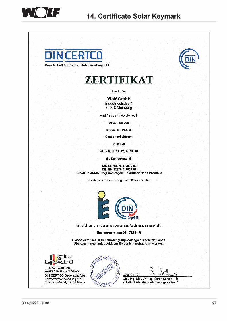
14. Certificate Solar Keymark
28 30 62 293_0408
Wolf GmbH · Postfach 1380 · D-84048 Mainburg · Tel. +49 8751/74-0 · Fax +49 8751/741600 · Internet: www.wolf-heiztechnik.de
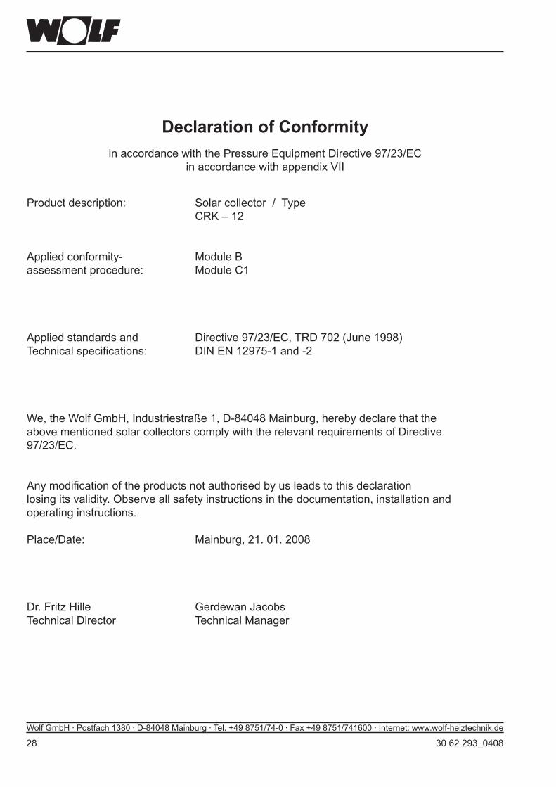
Declaration of ConformityinaccordancewiththePressureEquipmentDirective97/23/EC
inaccordancewithappendixVII
Product description: Solar collector / Type CRK – 12
Applied conformity- Module Bassessment procedure: Module C1
Appliedstandardsand Directive97/23/EC,TRD702(June1998)Technicalspecifications: DINEN12975-1and-2
We, the Wolf GmbH, Industriestraße 1, D-84048 Mainburg, hereby declare that the above mentioned solar collectors comply with the relevant requirements of Directive 97/23/EC.
Anymodificationoftheproductsnotauthorisedbyusleadstothisdeclarationlosingitsvalidity.Observeallsafetyinstructionsinthedocumentation,installationandoperating instructions.
Place/Date: Mainburg, 21. 01. 2008
Dr. Fritz Hille Gerdewan JacobsTechnical Director Technical Manager